general building inspectorate approval
TRANSCRIPT

Translated from German / page 1 of 28 :
80012.05
This English translation of the German original version has not been verified by the German Institute for Construction Engineering (DIBt).
D E U T S C H E S I N S T I T U T F Ü R B A U T E C H N I K GERMAN INSTITUTE FOR CONSTRUCTION ENGINEERING
Public-law agency
10829 Berlin, 03 February 2006 Kolonnenstrasse 30 L Telephone: 030 78730-296 Facsimile: 030 78730-320 File#: III 59-1.42.3-25/03
General Building Inspectorate Approval
Approval no.: Z-42.3-385
Applicant: Epros Umweltschutztechnik GmbH
Dr.-Alfred-Herrhausen-Allee 36 47228 Duisburg
Object of approval: “epros DrainPacker method” for the rehabilitation of buried
damaged sewer lines with nominal diameters from DN 100 to DN 800 using point and part liners (collectively also referred to as ”patch liners”)
Valid until: 31 January 2011 The above mentioned object is hereby granted general approval by the Building Inspectorate. This General Building Inspectorate Approval covers 17 pages and eleven appendices.
[DIBt seal]
Translated from German / page 2 of 28 :
Page 2 of the General Building Inspectorate Approval No. Z-42.3-385 of 03 February 2006
80012.05
This English translation of the German original version has not been verified by the German Institute for Construction Engineering (DIBt).
I. GENERAL PROVISIONS 1 The General Building Inspectorate Approval is proof of the usability or applicability of the
object of approval for the purpose of the German Lands’ building regulations.
2 The General Building Inspectorate Approval is no substitute for permits, consents and certificates statutorily prescribed for the implementation of building projects.
3 The General Building Inspectorate Approval is granted without prejudice to any third-party rights including but not limited to private proprietary rights.
4 Manufacturers and distributors of the object of approval shall, notwithstanding any additional regulations laid down in the “Special Provisions”, provide the user of said object with copies of the General Building Inspectorate Approval and shall instruct the user to the effect that the General Building Inspectorate Approval must be kept at the point of use or application. Upon request, copies of the General Building Inspectorate Approval shall be provided to the authorities interested.
5 The General Building Inspectorate Approval may not be reproduced unless in total. Any publication of part of this Approval requires the consent of the German Institute for Construction Engineering. Texts and drawings of advertising materials shall not be contradictory to the General Building Inspectorate Approval. Translations of the General Building Inspectorate Approval must contain the information that the “translation of the German original version has not been verified by the German Institute for Construction Engineering”.
6 The General Building Inspectorate Approval is granted subject to revocation. The provisions of the General Building Inspectorate Approval may be altered by subsequent modifications and additions, especially when this is required by new technical findings.
[DIBt seal]

Translated from German / page 3 of 28 :
Page 3 of the General Building Inspectorate Approval No. Z-42.3-385 of 03 February 2006
80012.05
This English translation of the German original version has not been verified by the German Institute for Construction Engineering (DIBt).
II. SPECIAL PROVISIONS
1 Object of approval and scope of application
This General Building Inspectorate Approval applies to the cast-in-place point and part pipelining (CIPP) method called “epros DrainPacker repair system” (Appendices 1 to 3) using the two-component silicate resin system called “epros resin type-W”, “type-W01” (“winter resins”) and “type-S” (“summer resin”) for the rehabilitation of damaged sewer lines with circular cross sections in the nominal diameters from DN 100 to DN 800. This Approval applies to the rehabilitation of sewer lines intended for the discharge of sewage as laid down in the standard DIN 1986-31.
The point and part lining method can be used for the rehabilitation of sewer lines made of concrete, reinforced concrete, vitrified clay, asbestos cement, cast iron, GRP and PVC-U if the cross section of the sewer to be repaired meets the method-related requirements as well as the needs of structural stability.
The point and part lining method can be used, independently of said pipe material of the host line, for the repair of cracks (e.g. radial cracks, longitudinal cracks, and combinations of both), mechanical wear, corrosion, as well as for the sealing of lateral connections and leaking pipe joints on the condition that the host pipe-soil system in itself is still self-supporting (e.g. longitudinal cracks with low pipe deformation and verified functional side bedding, if necessary, this condition needs to be checked e.g. by long-term observations and/or driving rod tests).
For the repair of damaged sewer pipes according to the point and part lining method, a resin-wetted glass fibre matting composed of resin-wetted random/woven fibre layers is moved through the sewer pipe to the spot of repair by means of an inflatable packer (“DrainPacker”), which is then inflated to pressurise the glass fibre mat to the host pipe wall. The packer remains in that position until curing is complete.
2.1 Properties and composition 2.1.1 Materials of the method components 2.1.1.1 Glass fibre material (Appendix 1, Picture 1)
The resin system shall use no carrier material other than glass fibre mats designated “CRF(+) matting” composed of woven and random-laid fibre glass mats under DIN 1259-12 and DIN 61853-13 and DIN 61853-24 as well as DIN 61854-15 in accordance with the recipe information lodged with the German Institute for Construction Engineering. The same recipe shall also be kept with the third-party inspection body. Each continuous roving fibreglass mat consists of a woven glass layer and a random-fibre layer sewn to one another.
[DIBt seal]
1 DIN 1986-3 Drainage facilities for buildings and properties – Part 3: Rules for operation
and maintenance; issue:2004-11 2 DIN 1259-1 Glass – Part 1: Terminology for glass types and groups; issue:2001-09 3 DIN 61853-1 Textile glass; textile glass mats for plastics reinforcement; technical delivery
conditions; issue:1987-04 4 DIN 61853-2 Textile glass; textile glass mats for plastics reinforcement; classification,
application; issue:1987-04 5 DIN 61854-1 Textile glass; woven glass fabrics for plastics reinforcement; woven glass
filament fabric and woven roving; technical delivery conditions; issue:1987-04

Translated from German / page 4 of 28 :
Page 4 of the General Building Inspectorate Approval No. Z-42.3-385 of 03 February 2006
80012.05
This English translation of the German original version has not been verified by the German Institute for Construction Engineering (DIBt).
The glass fibre mats have the following properties prior to application: – Mass per unit area: 1050 g/m² ± 10% according to ISO 33746
– Thickness: 1.6 mm ± 15% – Width: 400 mm to 2500 mm according to ISO 50257
2.1.1.2 Resin components The silicate resin system to be used, which is “epros resin type-W”, “type-W01” and “type-S”, consists of the components A (hardener) and B (resin). The combination of the two components must correspond to the recipe information kept with the German Institute for Construction Engineering. A so-called "winter quality” type-W and type-W01 as well as a so-called “summer quality” type-S are used for component B. To avoid property changes, the equipment coming in contact with component B, e.g. barrels, other containers, lines, must contain no water. • Component A (hardener): The hardener shows the following properties prior to application. – Density @ 20°C: 1.55 g/cm³ ± 0.01 g/cm³ – Viscosity @ 20°C: 600 mPa x s ± 100 mPa x s – pH: 13.0 ± 0.2 [DIBt – Colour: white seal] • Component B (resin): a) The silicate resin type-W01 shows the following properties prior to application. – Density @ 25°C: 1.190 g/cm³ ± 0.015 g/cm³ – Viscosity @ 25°C: 215 mPa x s ± 15 mPa x s – Pot time @ 20°C 6 min ± 1 min – Bending force: 1800 N ± 200 N – Colour: brown b) The silicate resin type-W shows the following properties prior to application. – Density @ 25°C: 1.240 g/cm³ ± 0.015 g/cm³ – Viscosity @ 25°C: 175 mPa x s ± 15 mPa x s – Pot time @ 20°C 14.5 min ± 1 min – Bending force: 1600 N ± 150 N – Colour: brown c) The silicate resin type-S shows the following properties prior to application: – Density @ 25°C: 1.240 g/cm³ ± 0.015 g/cm³ – Viscosity @ 25°C: 210 mPa x s ± 15 mPa x s – Pot time @ 20°C 31 min ± 2 min – Bending force: 1700 N ± 150 N – Colour: brown The silicate resin systems are in compliance with the IR spectrums kept with the German Institute for Construction Engineering. The IR spectrums shall also be lodged with the third-party inspection body.
6 ISO 3374 Reinforcement products - Mats and fabrics - Determination of mass per unit
area; issue:2000-06 7 ISO 5025 Reinforcement products - Woven fabrics - Determination of width and length;
issue:1997-12

Translated from German / page 5 of 28 :
Page 5 of the General Building Inspectorate Approval No. Z-42.3-385 of 03 February 2006
80012.05
This English translation of the German original version has not been verified by the German Institute for Construction Engineering (DIBt).
2.1.2 Environmental compatibility As to potential impacts on soil hygiene, there are no concerns or objections to the application and use of the resin components A and B and glass fibre mats of the point and part liner method according to the recipe data kept with the German Institute for Construction Engineering. This environmental compatibility statement shall be valid only if and where the Special Provisions of this General Building Inspectorate Approval are complied with. The approval authority reserved to local water agencies or building inspectorates, especially in protected catchment areas, shall not be affected thereby.
2.1.3 Wall thickness and wall structure A repair job according to this system uses resin-wetted point or part liners having a minimum wall thickness of 4 mm after installation and complete cure, regardless of the nominal diameter. The point or part liner installed in the host pipe must be at least three-layered. The liner’s wall structure must be made up of an outer random-fibre layer and an inner random-fibre layer with a woven glass fibre layer in between (Appendix 2, Picture 11).
2.1.4 Physical characteristics of the cured point or part liner The glass fibre mats (laminates) wetted with the resin system must show the following characteristic values after complete cure: 1. Density after DIN EN ISO 1183-18:
– Type-W01: ≈ 1.451 g/cm³ – Type-W: ≈ 1.518 g/cm³ – Type-S: ≈ 1.508 g/cm³ – Mixture of type-W and type-S: ≈ 1.538 g/cm²
2. Calcination after DIN EN ISO 11729:
– Type-W01: ≥ 57% – Type-W: ≥ 52% [DIBt – Type-S: ≥ 58% seal] – Mixture of type-W and type-S: ≥ 58%
3. Initial E-modulus after DIN EN 16869-210:
– Type-W01: ≥ 5546 N/mm² – Type-W: ≥ 7850 N/mm² – Type-S: ≥ 6678 N/mm² – Mixture of type-W and type-S: ≥ 6439 N/mm²
4. Bending strength after DIN EN ISO 17811:
– Bending strength with type-W01: ≥ 161 N/mm² – Bending strength with type-W: ≥ 152 N/mm² – Bending strength with type-S: ≥ 143 N/mm² – Bending strength with mixture of type-W and type-S: ≥ 124 N/mm²
8 DIN EN ISO 1183-1 Plastics - Methods for determining the density of non-cellular plasticsPart 1: Immersion method, liquid pyknometer method and titration method(ISO 1183-1:2004); German version EN ISO 1183-1:2004; issue:2004-05
9 DIN EN ISO 1172 Textile-glass-reinforced plastics - Prepregs, moulding compounds and laminates - Determination of the textile-glass and mineral-filler content; calcination methods (ISO 1172:1996); German version EN ISO 1172:1998; issue:1998-12
10 DIN EN 61869-2 Pipes of glass fibre reinforced polyester resin, wound, filled – Part 2: General quality requirements; testing; issue: 1995-12
11 DIN EN ISO 178 Plastics - Determination of flexural properties (ISO 178:2001); German versionEN ISO 178:2003; issue:2003-06 in conjunction with (draft standard) DIN EN ISO 178/A1, issue:2004-10 Plastics - Determination of flexural properties - Amendment 1: Precision statement (ISO 178:2001/Amd 1:2004); German version EN ISO 178:2001/prA1:2004

Translated from German / page 6 of 28 :
Page 6 of the General Building Inspectorate Approval No. Z-42.3-385 of 03 February 2006
80012.05
This English translation of the German original version has not been verified by the German Institute for Construction Engineering (DIBt).
2.1.5 Physical characteristics of the cured silicate resin mixture The cured resin mixture of the components A and B shows the following characteristic values: 1. Density after DIN EN ISO 1183-18:
– Type-W01: ≈ 1.295 g/cm³ – Type-W: ≈ 1.286 g/cm³ – Type-S: ≈ 1.343 g/cm³ – Mixture of type-W and type-S: ≈ 1.341 g/cm³
2. Tensile strength after DIN EN ISO 52712:
– Type-W01: ≥ 14.9 N/mm² – Type-W: ≥ 15.0 N/mm² – Type-S: ≥ 15.0 N/mm² – Mixture of type-W and type-S: ≥ 14.5 N/mm²
3. E-modulus (tensile) after DIN EN ISO 52712:
– Type-W01: ≥ 210 N/mm² – Type-W: ≥ 201 N/mm² – Type-S: ≥ 211 N/mm² – Mixture of type-W and type-S: ≥ 195 N/mm²
4. Compressive strength after DIN EN ISO 60413:
– Type-W01: ≥ 44.8 N/mm² – Type-W: ≥ 45.3 N/mm² – Type-S: ≥ 48.3 N/mm² – Mixture of type-W and type-S: ≥ 38.4 N/mm²
5. E-modulus (compression) after DIN EN ISO 60413:
– Type-W01: ≥ 739 N/mm² – Type-W: ≥ 766 N/mm² – Type-S: ≥ 698 N/mm² – Mixture of type-W and type-S: ≥ 607 N/mm²
6. Shrinkage coefficient: – Type-W01: [DIBt 0.44% ± 0.04% – Type-W: seal] 0.22% ± 0.02% – Type-S: 0.19% ± 0.01% – Mixture of type-W and type-S: 0.21% ± 0.02%
2.2 Manufacture, packaging, transport, storage and identification 2.2.1 Manufacture of point and part liners
The glass fibre mats shall be manufactured in the sub-supplier’s factory with the minimum thicknesses stated in Section 2.1.1.1. The Applicant shall check and make sure the specified lengths and wall thicknesses are observed by the sub-supplier.
12 DIN EN ISO 527 Plastics - Determination of tensile properties - Part 1: General principles
(ISO 527-1:1993 including Amendment 1:1994); German version EN ISO 527-1:1996; issue: 1996-04 - Part 2: Test conditions for moulding and extrusion plastics (ISO 527-2:1993 including Amendment 1:1994); German version EN ISO 527-2:1996; issue: 1996-07
13 DIN EN ISO 604 Plastics - Determination of compressive properties (ISO 604:2002); German version EN ISO 604:2003; issue:2003-12

Translated from German / page 7 of 28 :
Page 7 of the General Building Inspectorate Approval No. Z-42.3-385 of 03 February 2006
80012.05
This English translation of the German original version has not been verified by the German Institute for Construction Engineering (DIBt).
The Applicant shall obtain proof to make sure the resins and the hardener are in compliance with the recipe data. For this purpose, the Applicant will cause the sub-supplier to produce test reports 2.2 after DIN EN 1020414 upon each delivery. The scope of inspection for the incoming goods shall include the verification of the following properties of the resin components A (hardener) and B (resins: type-W01, type-W and type S). Properties of resins and hardener:
– Density – Viscosity
2.2.2 Packaging, transport, storage The glass fibre mats delivered by the sub-supplier shall be stored prior to use in the premises of the Applicant in a way to ensure the mats will not be damaged. The components (resins and hardener) delivered by the sub-supplier for resin impregnation on the given job site shall be stored until further use in suitable and separate hermetically closed containers in the premises of the Applicant. The storage temperature of +5°C to +25°C and the relative air humidity of 40% to 70% shall be observed. The shelf time is approximately six months following the day of the delivery and shall not be exceeded. The storage containers shall be protected from direct sunlight. They shall be designed such that the silicate resin (component B) and the hardener (component A) are kept in separate receptacles/containers. The usage amounts of each component as required for the repair jobs shall be withdrawn from the storage containers and then transported in suitable, separate and hermetically closed receptacles to the given place of application. There, the receptacles must be protected from weather. The glass fibre mats shall be transported in suitable transport containers to ensure they are not damaged. When and where the resin components are packed at the Applicant’s site, they shall be filled in suitable transport containers only (e.g. plastic canisters). Care shall be taken to ensure the component B is not filled in moist containers. The relevant rules and regulations of accident prevention as well as the instructions given in the Applicant’s procedures manual shall be observed during storage, handling and transport.
2.2.3 Identification The glass fibre mats and the transport containers of the resin components A and B shall be identified with the compliance mark in accordance with the applicable national compliance and conformity regulations, inclusive of the Approval number Z-42.3-385. Said identification is subject to the condition that the requirements set forth in Section 2.3 Proof of Compliance have been met. Additionally, the transport containers of the glass fibre mats shall be labelled with the following information: – Roll width – Total weight – Mass per unit area – Batch number In addition, the transport containers for the resins and the hardener shall be labelled with at least the following information: – Component designation – Winter or summer quality of component B – Temperature range for application: +0°C to +25°C – Holding capacity of storage container (volume or weight) [DIBt seal]
4 DIN EN 10204 Metallic products – types of inspection documents; German version
EN 10204:2004; issue: 2005-01

Translated from German / page 8 of 28 :
Page 8 of the General Building Inspectorate Approval No. Z-42.3-385 of 03 February 2006
80012.05
This English translation of the German original version has not been verified by the German Institute for Construction Engineering (DIBt).
– Where appropriate, the hazmat identification (in accordance with the relevant hazardous material regulation)
– Batch number
2.3 Proof of Compliance 2.3.1 General
The confirmation that the method components are in compliance with the provisions of this General Building Inspectorate Approval must be provided for each manufacturing plant by means of a certificate of compliance based on in-house production control and regular third-party inspection systems including initial testing of the method components in accordance with the following conditions. For issuing the certificate of compliance and for third-party inspection including associated product testing, the manufacturer shall call in a generally accepted certification body as well as an inspection body having general acceptance to this effect. The certification body shall, for information purposes, give the German Institute for Construction Engineering a copy of the Compliance Certificate issued by said body. In addition, the German Institute for Construction Engineering shall be given for information a copy of the initial test report.
2.3.2 In-house production control In-house production control shall be implemented and carried out in every manufacturing plant. In-house production control shall mean the continuous inspection or monitoring of production by the manufacturer to ensure that the construction products made by the manufacturer comply with the provisions of this General Building Inspectorate Approval. In-house production control shall include the following minimum requirements: – Description and inspection of the base material
For each delivery of the incoming components, which are glass fibre mats, resin and hardener, the operator of the manufacturing plant shall check and make sure the properties required at Section 2.1.1 are met. For this purpose, the operator of the manufacturing plant must cause each of the sub-suppliers of the resin components to submit corresponding test reports 2.2 and the manufacturing plant of the sub-suppliers of the glass fibre mats to submit certificates of compliance with the order 2.1 after DIN EN 1020414. In addition, the incoming goods inspection shall include a random check verifying the properties specified in Section 2.1.1.1 and Section 2.1.1.2 hereof in accordance with the recipe statements kept with the German Institute for Construction Engineering. Furthermore, the modulus of elasticity of the ready-for-use resin mixture as given in Section 2.1.5 hereof shall be tested on at least three specimens in compliance with the specifications of Table 1 of DIN 16946-115, item 6, according to the test conditions laid down in Section 5.2.1 hereof and according to DIN EN ISO 52712 using the tensile test procedure. Shrinkage according to Section 2.1.5 hereof shall be tested for each resin delivery on at least three specimens with the dimensions 150 mm x 10 mm x 5 mm.
– Checks and inspections to be performed during manufacture It shall be checked that the requirements laid down in Section 2.2.1 are fulfilled.
– Checks and inspections of containers Each resin batch shall be checked for meeting the identification requirements set forth in Section 2.2.3. [DIBt
seal] 4 DIN 16946-1 Cured casting resins, testing; issue: 1989-03
Translated from German / page 9 of 28 :
Page 9 of the General Building Inspectorate Approval No. Z-42.3-385 of 03 February 2006
80012.05
This English translation of the German original version has not been verified by the German Institute for Construction Engineering (DIBt).
The results of in-house production controls shall be recorded. The records shall contain at least the following information: – Designation of the construction product or of the base product and its components – Type of control, test or inspection – Date when the construction product or base material was manufactured and
inspected – Result of control checks and inspections and, where appropriate, comparison with
the specifications – Signature of the person responsible for in-house production control The records shall be kept for at least five years and submitted to the external inspection body called in for third-party inspection. On request, they shall be submitted to the German Institute for Construction Engineering and to the competent supreme building inspection authority. If the inspection result is not satisfactory, the manufacturer shall immediately take the actions required for correcting the defect. Non-conforming construction products shall be handled in a way to ensure there is no confusion possible with conforming products. Once the defect has been corrected, the failed test or inspection shall be repeated immediately – where technically feasible and required for proving the success of the corrective action.
2.3.3 Third-party inspection In every manufacturing factory, the in-house production control shall be inspected and verified by an external body at regular intervals, but at least twice a year. The scope of third-party inspection includes an original inspection (initial testing) of the method components. In-house production control shall be verified by means of random checks within the scope of third-party inspection. Compliance with the requirements under the Sections 2.1.1 and 2.2.3 shall be verified. Furthermore, random checks shall be performed as to compliance with the manufacturing requirements laid down in Section 2.2.1. These include the verification of the curing behaviour, the densities of the components A and B according to Section 2.1.1.2, the storage stability and mass per unit area of the “CRF(+) matting”, as well as the IR spectroscopies. The generally accepted inspection body is responsible for sampling and testing. During third-party inspection, the certificates of compliance with the order 2.1 and the test reports 2.2 after DIN EN 102044 shall be verified, too. The results of the certification and third-party inspection processes shall be kept for no less than five years. When requested, the certification body or the inspection body shall submit them to the German Institute for Construction Engineering and to the competent supreme building inspection authority.
3 Provisions for the design of the renovation job
The necessary pipeline data shall be verified, e.g. routing, depth, position of laterals, manhole depths, groundwater, pipe joints, hydraulic conditions, inspection holes, cleaning intervals. Existing video takes must be analyzed for application-specific evaluation. The correctness of the data must be verified on the job site. The condition of the existing sewer line of the property drainage system must be assessed in terms of the applicability of the pipelining method. The hydraulic capacity of the sewer lines shall not be affected by the installation of a pipeliner. If necessary, appropriate proof shall be furnished.
[DIBt seal]

Translated from German / page 10 of 28 :
Page 10 of the General Building Inspectorate Approval No. Z-42.3-385 of 03 February 2006
80012.05
This English translation of the German original version has not been verified by the German Institute for Construction Engineering (DIBt).
4 Provisions for job performance
4.1 General The point and part cast-in-place pipelining method can be used for the following structural conditions: a) From the start to the end point b) From the start point down into a pipe run for a defined length with no further
manhole or access pit being required c) Lateral connections, from the start point down to the main line/lateral interface The start or end points can be a manhole, an inspection or cleaning hole, or an open pipe socket. A line bend of up to 90 degrees in nominal diameters from DN 100 to DN 150 can be relined by means of appropriate packers able to negotiate bends. Wrinkles in straight pipeline sections are allowed if not exceeding 2% of the nominal diameter according to DIN EN 13566-416. No wrinkles at all are allowed in the invert. Wrinkles in line bends may not exceed 5% of the nominal diameter according to DIN EN 13566-416. The Applicant shall prepare a procedures manual describing each of the steps to be performed with reference to the way how the pipelining method is to be executed. The Applicant shall also ensure the installers are sufficiently familiarised with the method. The sufficient technical knowledge can be documented for the installer company by means of an appropriate quality mark of the German Association for Sewer Construction Quality Protection Güteschutz Kanalbau e.V.17.
4.2 Equipment and installations Includes but is not limited to the equipment and installations required for implementing the CIPP lining method: – Equipment for sewer cleaning operations – Equipment for containment – Equipment for sewer inspection (refer to ATV-M 143-218) – Installations for pipelining operations:
• Glass fibre matting for the nominal diameters to be relined, [DIBt • Containers with resin (component B) and hardener (component A) seal] • Unit for dosing and filling the resin components • Mixing container with mixing tool (stirrer) • Weatherproof impregnation point • Base sheeting • “DrainPacker” device for the given pipe diameters and accessories • Separating agent and PE film (stretch film) for the packer • Camera, control unit with screen
16 DIN EN 13566-4 Plastics piping systems for renovation of underground non-pressure drainage
and sewerage networks (gravity sewers) – Part 4: Lining with cured-in-place pipes; German version EN 13566-4:2002; issue: 2003-04
17 Güteschutz Kanalbau e.V.; Linzer Str. 21, Bad Honnef, phone: (02224) 9384-0; fax: (02224) 9384-84 18 ATV-M 143-2 Information Sheet of the Wastewater Association – Part 2: Optical
inspection – inspection, repair, renovation and renewal of sewers and drains; issue: 1999-04

Translated from German / page 11 of 28 :
Page 11 of the General Building Inspectorate Approval No. Z-42.3-385 of 03 February 2006
80012.05
This English translation of the German original version has not been verified by the German Institute for Construction Engineering (DIBt).
• Air push rods for positioning the packer • Safety and pull-in ropes • Pressure hoses for connection with the packer including pressure monitoring
device • Compressor, air hoses, air regulators • Inflatable pipe plugs, or stop discs for the given nominal diameters • Water supply • Power supply • Containers for residual waste • Temperature sensor • Small equipment • Pneumatic drill • Hand tools, e.g. scissors, spatulas, rollers etc. • Social and sanitary rooms where necessary
Any electrical equipment to be introduced into the pipe such as CCTV cameras (or so-called crawlers) must be in compliance with the VDE regulations.
4.3 Performance of pipelining work 4.3.1 Preparatory work
Before starting the pipelining job, it is imperative to ensure the sewer to be renovated is out of service; if necessary, the service flow is to be stopped by pipe plugs and bypassed. In preparation for the pipelining job, the pipe run to be relined, inclusive of its lateral connections, shall be put out of service. Then the pipe run shall be cleaned with a high-pressure water equipment (so-called “jetting”). In case the inner surfaces of the defective line are smooth-walled and in case jetter operation is not able to remove existing deposits (the so-called “sewer slime”) to the extent required for the pipelining method, the installer should strip the surface (remove the “sewer slime”) as required by the damage pattern. Obstacles to service flows shall be eliminated. The inner pipe wall surfaces in the region of stop discs or plugs must be even. The exact positions of the damages and those of the laterals shall be measured over the cleaned pipe length. Before starting the actual pipelining operation, it is necessary to measure the ambient temperature to assess whether or not the required temperature limits of the method can be observed. The rules and regulations of accident prevention applicable to the use of the pipelining method shall be complied with. No pipelining method equipment to be introduced into the defective sewer section shall be used unless and until it has been ensured by appropriate inspection that there are no inflammable gases in the line section to be repaired. More specifically, the relevant sections of the following codes and regulations shall be complied with: – GUV-R 126 (formerly GUV 17.6)19 – ATV Information Sheet M 143-218 [DIBt – ATV Worksheet A 14020 seal]
19 GUV-R 126 Safety rules for work in confined spaces of wastewater facilities, Federal
German Association of Accident Insurers (GUV), issue: 1996-03 20 ATV-A 140 Worksheet of the Wastewater Association – Rules for sewer operation
Part 1: Sewer system, – Sections 2 and 4.2 – issue: 1990-03

Translated from German / page 12 of 28 :
Page 12 of the General Building Inspectorate Approval No. Z-42.3-385 of 03 February 2006
80012.05
This English translation of the German original version has not been verified by the German Institute for Construction Engineering (DIBt).
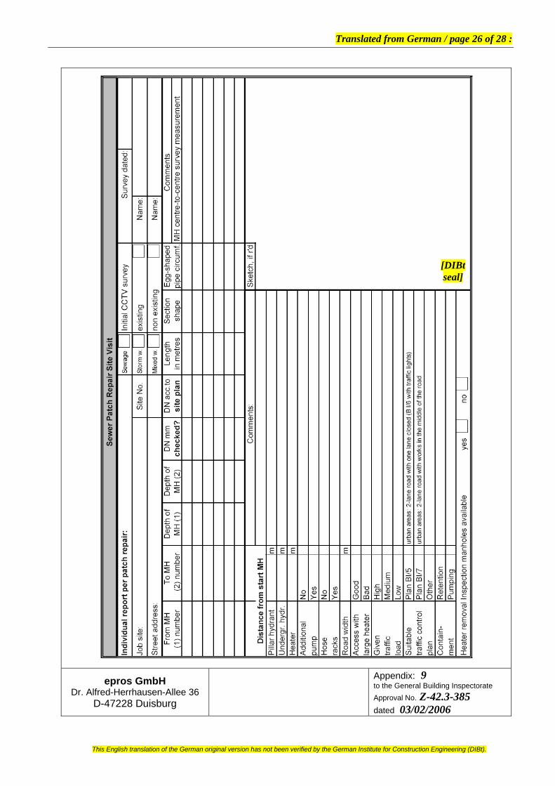
The data stated in Section 3 shall be checked on the job site to make sure they are correct. The pipe run to be relined shall be cleaned with usual high-pressure cleaning equipment (jetters) to the same extent as is necessary to be able to perfectly recognise the pipe defects on the monitor during the optical inspection according to the Information Sheet ATV-M 143-218. Also, for any persons descending into manholes of sewer lines to be renovated as well as in all steps of the pipelining method, the relevant regulations of accident prevention shall be complied with. The operations of formatting the glass fibre mats according to Section 4.3.3.1, mixing the resin according to Section 4.3.3.2 and resin impregnation according to Section 4.3.3.3 shall be performed in a waterproof closed room or shelter (e.g. in the installation vehicle) on even supports free of dirt or contaminations of any type. The pot time given in Table 1 shall be adjusted to the given pipelining job by mixing the resin according to Section 4.3.3.2 in a way to ensure that the point liner or part liner remains in perfect contact with the surface of the defective sewer wall over the full length of repair during said time, i.e. without cure starting. The steps required for the performance of the method shall be recorded for each impregnation and pipelining job on specific report forms (e.g. Appendices 9 and 10).
4.3.2 Inspection of incoming method components on the job site The transport containers of the method components shall be checked for proper identification as specified in Section 2.2.3. The circumference dimension of the glass fibre mats as referred to the given pipelining job shall be checked before the mat is wetted with resin. It must also be checked that the prescribed pre-impregnation storage temperature is maintained between +15°C and +20°C.
4.3.3 Formatting and impregnation of the glass fibre mats 4.3.3.1 How to cut the glass fibre matting
The unrolled glass fibre matting is to be cut to size on the job site (Appendix 1, picture 2), on a work table located in a weatherproof or air-conditioned room or in the installation vehicle, with the cut length being approximately 0.5 m to 5.0 m (projected single-run length, Appendix 6) multiplied with 3.5 times the diameter for a three-layered point or part liner inclusive of the overlapping lengths (Appendix 3, picture 13). The glass fibre mats should have a width of at least 1.27 m to allow for the minimum single-run length of 0.5 m of a three-layered point liner. It is important to ensure that the glass fibre mats are cut such that the front and end regions of the later point or part liner closely fit the host pipe with an extending portion of at least 5 cm beyond the defect.
4.3.3.2 How to mix the resin The silicate system is composed of the catalyst component A (hardener) and the resin component B (silicate resin type-W, type-W01, and type-S). One volume part of component A shall be mixed with two volume parts of component B (see tables 1 and 2). The container of component B (hardener) must be hermetically closed again immediately after the removal of the required amount. The resin usage amounts shall be determined for each specific application in accordance with the statements given in Table 3 and Table 4 (Appendix 1, picture 4). The components A and B shall be mixed in a mixing container using a stirring device (e.g. electrically operated) in a way to achieve a bubble-free resin mixture with a uniform colour (Appendix 1, picture 5). The resin mixture as well as the temperature conditions shall be recorded in a report according to Section 4.3.1. Also, a retention sample shall be taken from each resin batch on the job site and then checked and reported for its curing behaviour.
[DIBt seal]

Translated from German / page 13 of 28 :
Page 13 of the General Building Inspectorate Approval No. Z-42.3-385 of 03 February 2006
80012.05
This English translation of the German original version has not been verified by the German Institute for Construction Engineering (DIBt).
Table 1: “Mixing ratio of the components A and B (type-W and type-S)”
Mixing ratio by volume Nr. Comp. A:
hardener Comp. B:
resin type-W Comp. B:
resin type-S
Pot time at 20°C
min
Cure timeat 15°C
min 1 3 6 – 15 115 2 3 5 1 18 120 3 3 4 2 21 140 4 3 3 3 25 165 5 3 2 4 28 180 6 3 1 5 31 200 7 3 – 6 32 260
Table 2: “Mixing ratio of the components A and B (type-W01)”
Mixing ratio by volume Nr. Comp. A:
hardener Comp. B:
resin type-W01
Pot time
at 10°C min
Pot time
at 22°C min
Cure time
at 12°C min
Cure time
at 20°C min
1 1 2 13-15 4.5-7.5 35 20
[DIBt Table 3: “Determination of usage amounts for components A and B” seal]
Nom. diam.
Glass fibre matting designated ”CRF(+)” Resin system
DN Length Width Area Mat
layers folded
Resin factor2)
Resinbatchtotal
Comp. A
hardener
Comp.B
resin mm m m m² units Ltr/m² Litres Litres Litres 100 0.35 1.27 0.44 3 1.6 0.75 0.25 0.50 125 0.45 1.27 0.57 3 1.6 0.90 0.30 0.60 150 0.55 1.27 0.70 3 1.6 1.20 0.40 0.80 200 0.70 1.27 0.89 3 1.6 1.50 0.50 1.00 250 0.90 1.27 1.14 3 1.6 1.80 0.60 1.20 300 1.10 1.27 1.40 3 1.6 2.40 0.80 1.60 400 1.40 1.27 1.78 3 1.6 2.85 0.95 1.90 500 1.75 1.27 2.22 3 1.6 3.60 1.20 2.40 600 2.10 1.27 2.67 3 1.6 4.20 1.40 2.80 700 2.50 1.27 3.18 3 1.6 5.10 1.70 3.40 800 2.85 1.27 3.62 3 1.6 6.00 2.00 4.00
1) for a lining length of 0.50 m 2) specific usage amount for a fibreglass weight of 1050 g/m²

Translated from German / page 14 of 28 :
Page 14 of the General Building Inspectorate Approval No. Z-42.3-385 of 03 February 2006
80012.05
This English translation of the German original version has not been verified by the German Institute for Construction Engineering (DIBt).
4.3.3.3 Wetting with resin After mixing, the resin batch shall be applied with an appropriate spatula homogeneously onto the spread glass fibre mat (first layer) and into the woven glass top layer by means of crossing movements all over the fabric (Appendix 1, picture 6, and Appendix 2, picture 7). Then, the glass fibre mat is to be folded once to the left (second layer; Appendix 2, picture 8) and the random-fibre side shall be impregnated with the resin system in the same way as in the previous steps. Then, the glass fibre mat shall be folded to the right over the second layer and the resin system shall once more be applied with a spatula onto the mat, now with the random-fibre layer up (third layer; Appendix 2, picture 9). The then three-layered glass fibre mat is to be turned over and the resin system to be applied onto the random-fibre backside of the laminate (Appendix 2, picture 10). For point or part liners having more than three layers, it is necessary to place additional glass fibre mats onto the first mat and wet them with resin as additional operation (Appendix 5) in between the steps described in picture 7 and picture 8 of Appendix 2, prior to folding. Then the steps are the same as those described for a three-layered point or patch liner. The minimum wall thickness of the point or part liners shall be observed as laid down in Section 2.1.3. For the avoidance of entrapped air, a roller should be used to press the resin into the fabric. Due to the previously described step of folding the fabric into an at least three-layered point or part liner, one random-fibre layer of the glass fibre mat faces the service flow and the other random-fibre side is in contact with the host pipe. So the woven glass layer of the glass fibre matting is sandwiched between the layers with random fibre orientation (Appendix 2, picture 11). The cure time and the ambient temperature as well as the temperature in the sewer line shall be recorded in the report set forth in Section 4.3.1.
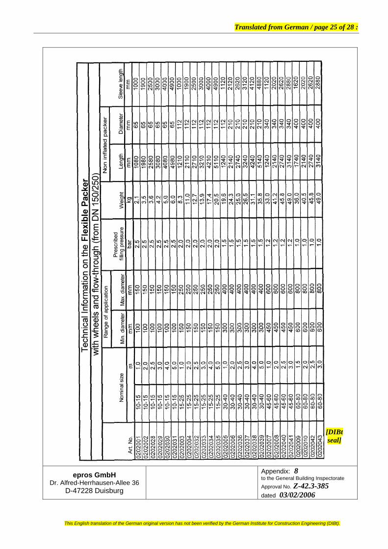
4.3.4 Point or part liner installation in the host pipe The impregnated point liner or part liner is installed by means of a packer. The rubber sleeve of the host pipe-specific packer shall be wrapped with a protective PE film (Appendix 1, picture 3), which forms a separating layer for the later removal of the packer from the sewer. For the selection of the appropriate packer, care shall be taken to ensure the outer diameter of the packer is some 50 mm to 80 mm smaller than the inner diameter (bore) of the host pipe (Appendices 7 and 8). The resin-wetted glass fibre mat shall be placed onto the packer and protected from slipping or falling (Appendix 2, picture 12 and Appendix 3, pictures 13 and 14). The repair job shall be performed only with packers equipped with rollers. Said rollers must be arranged such that the resin-wetted glass fibre mat will not contact the inner pipe wall when the packer is introduced into and moved inside the host pipe. Before the packer is introduced into the sewer to be repaired, an air hose from the compressor is to be connected to the packer. Then, the packer is pulled or pushed into the host pipe until and positioned at the point of repair as previously measured (Appendix 3, pictures 15 to 17). The application of compressed air according to Appendices 7 and 8 will cause the rubber sleeve of the packer to expand and thus press the resin-wetted glass fibre mat against the inner wall of the host pipe. The pressure shall be maintained until complete cure of the resin system (tables 1 and 2 as well as Appendix 5). Excessive resin is forced out at both ends of the point or patch liner to form hydraulically favourable conical transition zones with the host pipe. Eventually, the pressure will be released from the sleeve and the packer withdrawn from the pipe back to its start position (Appendix 3, picture 18). [DIBt
seal]

Translated from German / page 15 of 28 :
Page 15 of the General Building Inspectorate Approval No. Z-42.3-385 of 03 February 2006
80012.05
This English translation of the German original version has not been verified by the German Institute for Construction Engineering (DIBt).
5 Job data in the manhole
The following job data should be indicated by means of a permanent and readily legible inscription in the start or finish manhole of the pipelining job: – Type of pipelining operation – Designation of the pipe run – Nominal diameter – Wall thickness of the liner – Year the relining work was performed
6 Final inspection and tightness test
Once the pipelining job is complete, the relined pipe section shall undergo optical inspection with appropriate proof and documentation (Appendix 11) for verification that any residual waste material has been removed and that there are no wrinkles impairing the hydraulic capacity.
After complete cure of the point or part liner, the sewer line shall be subjected to a tightness test according to DIN EN 161021. Then, the service can be reinstated in the repaired sewer.
7 Testing of samples
7.1 Curing
At least four times a year, the installer shall make a point or part liner in the nominal diameter of the last pipelining job using a test pipe (e.g. a PVC U-pipe) on the given job site. The circular ring sample thus obtained shall be tested at least twice a year for its short-term E-modulus (1-hour value, 24-hour value). The 1-hour value and the 24-hour value shall be used for checking whether creep is Kn ≤ 11 % according to the following formula:
E1h – E24h Kn = E1h x 100 [DIBt
seal]
7.3 Water tightness of the samples
The water tightness of the cured point or part liner can be tested either on a circular liner segment (ring) or on specimens taken from the cured point or part liner. Before testing, it may be necessary to clear the point or part liner from residual separating foil that had been used to protect the packer.
The test on specimens may use either a positive pressure or a negative pressure of 0.5 bar.
In the negative pressure test, water is supplied to one end of the specimen. A negative pressure of 0.5 bar is applied for a load period of 30 minutes to check whether or not there is visible leakage of water at the other end of the specimen.
In the positive pressure test, a water pressure of 0.5 bar is applied. Again, it is to be checked whether or not the other end of the specimen shows any leakage.
21 DIN EN 1610 Construction and testing of drains and sewers;
German version EN 1610:1997; issue: 1997-10

Translated from German / page 16 of 28 :
Page 16 of the General Building Inspectorate Approval No. Z-42.3-385 of 03 February 2006
80012.05
This English translation of the German original version has not been verified by the German Institute for Construction Engineering (DIBt).
8 Declaration of Compliance for the performed pipelining job
The contractor must provide a confirmation that the relining job as performed complies with the provisions laid down in this General Building Inspectorate Approval by issuing a Declaration of Compliance based on the specifications given in Table 4 and Table 5. The Declaration of Compliance shall be accompanied by documents regarding the properties of the method components according to Section 2.1.1 and the inspection and test results according to Table 4 and Table 5.
The pipelining job manager or a technically competent representative of the job manager shall be present on the job site during the performance of the pipelining operation. He shall see to proper execution of the work according to the provisions laid down in Article 4 and in doing so, more specifically, he shall perform or arrange for the inspections and tests according to Table 4 and Table 5. The number and scope as specified shall be minimum requirements.
Table 4: “Inspections and tests accompanying the pipelining method”
Test object Type of requirement Frequency Optical inspection of the line according to 4.3.1
and ATV-M 143-218 before each pipelining job
Optical inspection of the line according to 6 and ATV-M 143-218
after each pipelining job
Equipment according to 4.2 Final inspection according to 6 Identification of containers of pipelining components
according to 2.2.3
Resin mixture, resin amount and cure behaviour of each point liner
Mixing report according to 4.3.3.2
Cure time and pressure in the packer
according to 4.3.4
each job site
The pipelining job manager or his technically competent representative shall arrange for the tests mentioned in Table 5. The samples for the tests mentioned in Table 5 shall be taken from the above described sample pipes.
Table 5: “Tests to be carried out on specimens”
Test object Type of requirement Frequency Short-term E-modulus (1-hour value and 24-hour value) and creep
according to 7.1
Physical characteristics according to 2.1.4 Water tightness of sample
without sheeting according to 7.2
every 6th month of prod. each installer
Wall thickness and wall structure
according to 2.1.3 [DIBtseal]
The test results shall be recorded and evaluated; they shall be submitted to the German Institute for Construction Engineering on request. The number and scope as specified in the tables shall be minimum requirements.

Translated from German / page 17 of 28 :
Page 17 of the General Building Inspectorate Approval No. Z-42.3-385 of 03 February 2006
80012.05
This English translation of the German original version has not been verified by the German Institute for Construction Engineering (DIBt).
8 Provisions for maintenance
During the validity period of this Approval, the Applicant shall always carry out optical inspections of six repaired sewer lines. The results thereof, including the associated description of the repaired defects, shall be submitted to the German Institute for Construction Engineering without special request during the validity of this Approval.
Prior to the expiry date of this Approval, three of the aforementioned pipelining jobs shall be subjected to a tightness test to be carried out at the expense of the Applicant under the direction of an expert, in addition to the tightness test performed immediately after the pipelining job.
Prof. Hoppe Attested [signature]
[DIBt seal]

Translated from German / page 18 of 28 :
This English translation of the German original version has not been verified by the German Institute for Construction Engineering (DIBt).
Sectional view of the glass fibre matting Preparation of the glass fibre matting
Wrap overlapping stretch film around the packer and tape the ends to fix them in place on the packer.
Determine the usage amount of resin, pour resin and hardener into the mixing container.
[DIBt seal]
Mix the resin and the hardener. Pour a portion of the epros resin system onto the
side with directional fibre orientation of the matting.
epros GmbH Dr. Alfred-Herrhausen-Allee 36
D-47228 Duisburg
Appendix: 1 to the General Building Inspectorate Approval No. Z-42.3-385 dated 03/02/2006

Translated from German / page 19 of 28 :
This English translation of the German original version has not been verified by the German Institute for Construction Engineering (DIBt).
Spread the epros resin system for impregnation evenly with the hand spatula.
Fold the impregnated glass fibre mat for appr. 1/3rd. Apply the epros resin system onto the random-fibre layer on top and spread the resin evenly with the hand spatula for homogenous impregnation
Fold the glass fibre mat again. Apply the epros resin system evenly onto the random-fibre layer on top and spread the resin evenly with the hand spatula for homogenous impregnation.
Turn over the glass fibre mat. Apply the epros resinsystem evenly onto the random-fibre layer on top and spread the resin evenly with the hand spatula for homogenous impregnation.
[DIBt seal]
Sectional view of the glass fibre mat impregnated with the epros resin system.
Place the impregnated glass fibre mat onto the packer.
epros GmbH Dr. Alfred-Herrhausen-Allee 36
D-47228 Duisburg
Appendix: 2 to the General Building Inspectorate Approval No. Z-42.3-385 dated 03/02/2006

Translated from German / page 20 of 28 :
This English translation of the German original version has not been verified by the German Institute for Construction Engineering (DIBt).
The glass fibre mat must be precut to overlapping Fix the glass fibre mat in place with binding wire. size.
Introduce the packer into the pipe. Push the packer to the point of repair and position
it properly.
[DIBt seal]
Inflate the packer with the authorised pressure. The wetted glass fibre mat will be pressed against the inner wall of the pipe.
After final cure of the liner, remove the air from the packer and remove the packer from the line.
epros GmbH Dr. Alfred-Herrhausen-Allee 36
D-47228 Duisburg
Appendix: 3 to the General Building Inspectorate Approval No. Z-42.3-385 dated 03/02/2006

Translated from German / page 21 of 28 :
This English translation of the German original version has not been verified by the German Institute for Construction Engineering (DIBt).
epros GmbH Dr. Alfred-Herrhausen-Allee 36
D-47228 Duisburg
Appendix: 4 to the General Building Inspectorate Approval No. Z-42.3-385 dated 03/02/2006
[DIBt seal]

Translated from German / page 22 of 28 :
This English translation of the German original version has not been verified by the German Institute for Construction Engineering (DIBt).
epros GmbH Dr. Alfred-Herrhausen-Allee 36
D-47228 Duisburg
Appendix: 5 to the General Building Inspectorate Approval No. Z-42.3-385 dated 03/02/2006
[DIBt seal]

Translated from German / page 23 of 28 :
This English translation of the German original version has not been verified by the German Institute for Construction Engineering (DIBt).
epros GmbH Dr. Alfred-Herrhausen-Allee 36
D-47228 Duisburg
Appendix: 6 to the General Building Inspectorate Approval No. Z-42.3-385 dated 03/02/2006
[DIBt seal]

Translated from German / page 24 of 28 :
This English translation of the German original version has not been verified by the German Institute for Construction Engineering (DIBt).
[DIBt seal]
epros GmbH Dr. Alfred-Herrhausen-Allee 36
D-47228 Duisburg
Appendix: 7 to the General Building Inspectorate Approval No. Z-42.3-385 dated 03/02/2006
Translated from German / page 25 of 28 :
This English translation of the German original version has not been verified by the German Institute for Construction Engineering (DIBt).
epros GmbH Dr. Alfred-Herrhausen-Allee 36
D-47228 Duisburg
Appendix: 8 to the General Building Inspectorate Approval No. Z-42.3-385 dated 03/02/2006
[DIBtseal]
Translated from German / page 26 of 28 :
This English translation of the German original version has not been verified by the German Institute for Construction Engineering (DIBt).
epros GmbH Dr. Alfred-Herrhausen-Allee 36
D-47228 Duisburg
Appendix: 9 to the General Building Inspectorate Approval No. Z-42.3-385 dated 03/02/2006
[DIBtseal]

Translated from German / page 27 of 28 :
This English translation of the German original version has not been verified by the German Institute for Construction Engineering (DIBt).
Installation & Manufacture Report Project No.: Client: Contractor: Town/city: Town/city: Street address: Street address: Contact: Contact: Telephone: Telephone: Job site: Town/city: From manhole: To manhole: Line section no. Material: Nominal
diameter: Point liner
positioned at:
Video cassette: Photo no.: Service maintained: yes no Permit required: yes no Containment required: yes no Site safety measures requ’d: yes no Line section prewashed: yes no Damage area free of faeces: yes no Damage area prepared by: HP water jetting Weather: dry humid mech. cleaning Outdoor temperature: °C cutter Sewer temperature: °C Dates of delivery: For component A: For component B:
Batch No.: Batch No.:
For CRF(+): For component B:
Batch No.: Batch No. Material tested by customer: yes no Specific handling problems: yes no Remark: Size of glass fibre matting: m X m gives m² Required total amount for mixing: Litres Mixing ratio: A: ______ Litres; Bw01: _______ Litres; Bw: _______ Litres; Bs: ________ Litres Contact pressure: bar Curing pressure: bar Pot time: specified maximum min actual pot time: min Cure time: specified minimum min actual cure time: min
[DIBTt seal] Date/signature
epros GmbH Dr. Alfred-Herrhausen-Allee 36
D-47228 Duisburg
Appendix: 10 to the General Building Inspectorate Approval No. Z-42.3-385 dated 03/02/2006

Translated from German / page 28 of 28 :
This English translation of the German original version has not been verified by the German Institute for Construction Engineering (DIBt).
epros GmbH Dr. Alfred-Herrhausen-Allee 36
D-47228 Duisburg
Appendix: 11 to the General Building Inspectorate Approval No. Z-42.3-385 dated 03/02/2006
[DIBtseal]