gefco 50k - t well drilling rig vehicle management codes ... · department of the air force...
TRANSCRIPT

DEPARTMENT OF THE AIR FORCE Headquarters US Air Force
QTP24-3-D513 14 January 2019
Washington, D.C. 20330-1030
GEFCO 50K - T Well Drilling Rig Vehicle Management Codes: D513, D751
QUALIFICATION TRAINING PACKAGE

CONTENTS SECTION 1—OVERVIEW ......................................................................................................... 3 1.1. Overview.......................................................................................................................................................... 3
SECTION 2—RESPONSIBILITIES .......................................................................................... 3 2.1. Responsibilities. .............................................................................................................................................. 3
SECTION 3—INTRODUCTION................................................................................................ 4 3.1. Objectives. ....................................................................................................................................................... 4
3.2. Desired Learning Outcomes. ......................................................................................................................... 4
3.3. Lesson Duration. ............................................................................................................................................. 5 3.4. Instructional References. ............................................................................................................................... 5
3.5. Instructional Training Aids and Equipment. ............................................................................................... 6
SECTION 4—TRAINEE PREPARATION ............................................................................... 6 4.1. Licensing Requirements. ................................................................................................................................ 6
4.2. Required Reading (Testable Material). ........................................................................................................ 6
SECTION 5—KNOWLEDGE LECTURE ................................................................................ 6 5.1. Overview of Training and Requirements. .................................................................................................... 6 5.2. Vehicle Inspection. .......................................................................................................................................... 8
5.3. Vehicle Safety and Equipment. ................................................................................................................... 11
5.4. Vehicle Operation. ........................................................................................................................................ 12
SECTION 6—EXPLANATION AND DEMONSTRATION. ................................................ 12 6.1. Instructor’s Preparation. ............................................................................................................................. 12
6.2. Safety Procedures and Equipment. ............................................................................................................. 12
6.3. Operator Maintenance Demonstration. ...................................................................................................... 13 6.4. Operation Demonstration. ........................................................................................................................... 13
Attachment 1—GLOSSARY OF REFERENCES AND SUPPORTING INFORMATION 15
Attachment 2--- GEFCO 50K – T WELL DRILLING RIG INSPECTION GUIDE 16
Attachment 3—SEVEN-STEP INSPECTION PROCESS 20

Section 1—OVERVIEW 1.1. Overview.
1.1.1. Send comments and suggested improvements on Air Force (AF) Form 847, Recommendation for Change of Publication through Air Force Installation and Mission Support Center (AFIMSC) functional managers via e-mail at [email protected]. 1.1.2. How to use this plan:
1.1.2.1. Instructor:
1.1.2.1.1. Provide overview of training, Section 2 and Section 3. 1.1.2.1.2. Instructor’s lesson plan for trainee preparation, give classroom lecture, Section 4. 1.1.2.1.3. Instructor’s lesson plan for knowledge lecture, Section 5. 1.1.2.1.4. Instructor’s lesson plan for demonstration, Section 6.
1.1.2.2. Trainee:
1.1.2.2.1. Reads this entire lesson plan prior to starting lecture. 1.1.2.2.2. Follows along with lecture using this lesson plan and its attachments. 1.1.2.2.3. Uses Attachment 2 and Attachment 3 as guides for vehicle inspection.
Section 2—RESPONSIBILITIES 2.1. Responsibilities.
2.1.1. The trainee shall:
2.1.1.1. Ensure the trainer explains the Air Force Qualification Training Plan (AFQTP) process and the trainee’s responsibilities. 2.1.1.2. Review the AFQTP/Module/Unit with the trainer. 2.1.1.3. The trainee should ask questions if he or she does not understand the objectives for each unit.
2.1.2. Instructor shall:

2.1.2.1. Review the AFQTP with the trainee. 2.1.2.2. Conduct knowledge training with the trainee using the AFQTP. 2.1.2.3. Sign-off the task(s).
2.1.3. The Certifier shall:
2.1.3.1. Evaluate the Airman’s task performance without assistance. 2.1.3.2. Sign-off the task(s).
Section 3—INTRODUCTION 3.1. Objectives.
3.1.1. Given lectures, demonstrations, hands-on operating session, trainees will be able to perform operator’s inspection and complete the performance tasks with zero instructor assists. 3.1.2. Train and qualify each trainee in safe operation and preventive maintenance of the various Gefco 50K – T well drilling rig listed below:
3.1.2.1. 35ft mast w/top head. 3.1.2.2. John Deere engine w/200 gallon fuel tank. 3.1.2.3. Main winch.
3.1.2.4. 5x6 mud pump. 3.1.2.5. Onboard compressor.
3.1.2.6. Axle lift. 3.1.2.7. Leveling jacks. 3.1.2.8. Onboard welder/generator.
3.1.3. This training will ensure the trainee becomes a qualified Gefco 50K – T well drilling rig operation; an operator who has the knowledge and skills to operate a Gefco 50K – T well drilling rig in a safe and proficient manner.
3.2. Desired Learning Outcomes.
3.2.1. Understand the safety precautions to be followed pre-, during-, and post-operation inspection of the Gefco 50K – T well drilling rig.

3.2.2. Understand the purpose of the Gefco 50K – T well drilling rig and its role in the mission. 3.2.3. Know the proper operator maintenance procedures of the Gefco 50K – T well drilling rig and use of AF Form 1800. 3.2.4. Be completely familiar with the safety features of the Gefco 50K – T well drilling rig. 3.2.5. Safely and proficiently operate the Gefco 50K – T well drilling rig.
3.3. Lesson Duration.
3.3.1. Recommended instructional and hands on training time is 20 hours:
Figure 3.1. Recommended Training Time for Training Activities.
Training Activity Training Time Trainee’s Preparation 2 Hours Instructor’s Lecture 3 Hours Instructor’s Demonstration 2 Hours Trainee’s Personal Experience (to build confidence and proficiency) Perform Operator Maintenance Operate the Vehicle
12 Hours
Trainee’s Performance Task Evaluation 1 Hour Note: This is a recommended time; training time may be more or less depending how quickly a trainee learns new tasks.
3.4. Instructional References.
3.4.1. Risk Management (RM) and Safety Principles in accordance with (IAW) Air Force Pamphlet (AFPAM) 90-803, Risk Management (RM) Guidance and Tools. 3.4.2. Applicable manufacturer’s operator’s manual.
3.4.3. Air Force Manual (AFMAN) 24-306, Operation of Air Force Government Motor Vehicles. 3.4.4. AF Form 1800, Operator’s Inspection Guide and Trouble Report (General Purpose Vehicles).
3.4.5. Air Force Instruction (AFI) 91-203, Air Force Consolidated Occupational Safety Instruction.
3.4.6. AFI 91-207, US Air Force Traffic Safety Program.
3.4.7. AFI 24-302, Vehicle Management.
3.4.8. Tractor-trailer lesson plan (transport). Note: The operator of the tractor-trailer will need to be licensed IAW AFI 24-301 and QTP 24-3-B280, Tractor-Trailer Vehicle Training Package.
3.5. Instructional Training Aids and Equipment.
3.5.1. Gefco 50K – T well drilling rig lesson plan. 3.5.2. Gefco 50K – T well drilling rig. 3.5.3. Applicable technical manuals or manufacturer’s operator’s manual. 3.5.4. AF Form 1800. 3.5.5. Videos (if locally produced). 3.5.6. Suitable training area.
Section 4—TRAINEE PREPARATION 4.1. Licensing Requirements.
4.1.1. Trainee must have in his/her possession a valid state driver’s license. 4.1.2. AF Form 171, Request for Driver’s Training and Addition to U.S. Government Drivers IAW AFI 24-301, Vehicle Operations.
4.1.3. Applicable local licensing jurisdiction requirements.
4.2. Required Reading (Testable Material).
4.2.1. Read this entire lesson plan. 4.2.2. Read AFMAN 24-306, Chapters 1-5, 7-9 and 12.
4.2.3. Read manufacturer’s operator’s manual for the vehicle being trained on.
Section 5—KNOWLEDGE LECTURE 5.1. Overview of Training and Requirements.
5.1.1. Training objectives:

5.1.1.1. Given lectures, demonstrations, hands-on operating session, trainees will be able to perform operator’s inspection and complete the performance tasks with zero instructor assists. 5.1.1.2. Train and qualify each trainee in safe operation and preventive maintenance of the various Gefco 50K – T well drilling rig. 5.1.1.3. This training will ensure the trainee becomes a familiar with various Gefco 50K – T well drilling rig — an operator who has the knowledge and skills to operate a Gefco 50K – T well drilling rig in a safe and proficient manner.
5.1.2. Desired learning outcomes:
5.1.2.1. Understand the safety precautions to be followed pre-, during-, and post-operation inspection of the Gefco 50K – T well drilling rig. 5.1.2.2. Be completely familiar with the safety features of the Gefco 50K – T well drilling rig. 5.1.2.3. Safely and proficiently operate the Gefco 50K – T well drilling rig. 5.1.2.4. Understand the purpose of the Gefco 50K – T well drilling rig.
5.1.2.4.1. The purpose of the Gefco 50K – T well drilling rig supply water in support of troop missions. 5.1.2.4.2. Role in the mission (Unit/Base/Community (during natural disasters)/Air Force).
5.1.3. Gefco 50K – T well drilling rig. The design of these vehicles varies depending on the vehicle manufacturer. Refer to the manufacturer’s operator’s manual for additional information on the specific vehicle you are operating. 5.1.4. Gefco 50K – T well drilling rig trailer-mounted, hydraulically operated designed drill to ground water baring formations. The trainee should be able to identify the following components of the rig.
5.1.4.1. Air bags/Outriggers. 5.1.4.2. Raise and lower mast (level before). 5.1.4.3. Hoist operation (main and utility). 5.1.4.4. Control lever for rotation; lowering, raising the top head. 5.1.4.5. Air compressor/mud pump control lever.

5.1.4.6. Air and mud control valves. 5.1.4.7. Table, breakout wrench, holding wrench and spinner operation. 5.1.4.8. 5x6 mud pump operation and maintenance 5.1.4.9. Single arm loader.
5.2. Vehicle Inspection.
5.2.1. Pre-operation inspection test. Use Attachment 2 as a walk-around guide along with AF Form 1800. 5.2.2. A Seven-Step Inspection Method will help ensure the inspection is the same each time it is conducted, and that nothing is left out. See Attachment 3 for the Seven-Step Inspection Method.
Note: If towing the rig, the operator will also be responsible for the inspection of the tractor-trailer IAW QTP 24-3-B280. Refer to QTP 24-3-B280 for additional inspection guidance.
5.2.3. Types of Inspection. If discrepancies are found the operator must report them to Vehicle Control Officer/Vehicle Control Non Commissioned Officer (VCO/VCNCO), the supervisor, and/or vehicle maintenance:
5.2.3.1. Pre-operation inspection – find items/problems that could cause accident or breakdown.
5.2.3.1.1. Rig maintenance to authorize continued use for all other maintenance discrepancies.
5.2.3.1.2. Cleanliness/damage/missing items.
5.2.3.1.3. Leaks (fuel/oil/coolant/hydraulic/air).
5.2.3.1.4. Fluid Levels; ensure level is within limits:
5.2.3.1.4.1. Engine oil.
5.2.3.1.4.2. Coolant.
5.2.3.1.4.3. Power steering fluid.
5.2.3.1.4.4. Gear box fluid.
5.2.3.1.4.5. Rock drill oil.

5.2.3.1.4.6. Hydraulic.
5.2.3.1.5. Battery; security, fluid, damage and corrosion.
5.2.3.1.6. All wheel rims (cracks, splits, etc.); check for loose or missing lug nuts.
5.2.3.1.7. All tires.
5.2.3.1.7.1. Proper inflation. Note: Notify VCO/VCNCO, the supervisor, and/or vehicle maintenance if completely flat.
5.2.3.1.7.2. Sidewalls, tread to include depth, bulges.
5.2.3.1.7.3. Cuts and abrasions.
5.2.3.1.7.4. Lug nuts.
5.2.3.1.8. Hydraulic pumps.
5.2.3.1.9. Drive belts; tension and fraying.
5.2.3.1.10. All hoses and wiring.
5.2.3.1.11. Shocks and brakes for leaks.
5.2.3.1.12. Suspension, airbags and shocks.
5.2.3.1.13. Boom hinge pin and cylinder pins. 5.2.3.1.14. Table. 5.2.3.1.15. Frame bolts and other fasteners.
5.2.3.1.16. Mirrors (towing vehicle).
5.2.3.1.17. Doors (towing vehicle).
5.2.3.1.18. Windows (towing vehicle).
5.2.3.1.19. Windshield and windshield wipers/washers (towing vehicle).
5.2.3.1.20. Seatbelts (towing vehicle). 5.2.3.1.21. Welds.

5.2.3.1.22. Visual and audible warning devices. 5.2.3.1.23. Hydraulic cylinders, hoses, and tubes to ensure that they are in place and show no evidence of damage, cracks or corrosion. 5.2.3.1.24. Wire rope and drums. 5.2.3.1.25. Pulleys and guide wheels. 5.2.3.1.26. Table bushings in place and available. 5.2.3.1.27. 5th wheel connection/compatibility. 5.2.3.1.28. Fuel cap; intact, not broken or damaged.
5.2.3.1.29. Catwalks and platforms not broken or damaged.
5.2.3.1.30. Wiring/lights/reflectors.
5.2.3.1.31. Fire Extinguisher. 5.2.3.1.32. Ensure the area is free from overhead obstructions such as trees, poles and power lines. 5.2.3.1.33. Operate the unit through the range of all functions to ensure proper operation. Be sure that everyone is clear of moving components. 5.2.3.1.34. Perform a pre-operation check from the all control positions. Make sure the emergency stop button works properly.
5.2.3.2. During-operation inspection.
5.2.3.2.1. All gauges and warning lights for proper operations.
5.2.3.2.1.1. Warning lights.
5.2.3.2.1.2. Gauges (oil pressure, fuel gauge, water temperature, voltage).
5.2.3.2.1.3. Indicators.
5.2.3.2.2. Listen for exhaust and air leaks. Listen for any unusual sounds.
5.2.3.2.3. Stay alert for any unusual smells or odors.
5.2.3.2.4. Stay alert for any abnormal vibrations or handling problems.
5.2.3.3. Post-operation inspection and report.

5.2.3.3.1. Ensure rig and components are cleaned.
5.2.3.3.2. Equipment is properly stowed.
5.2.3.3.3. Refueled.
5.2.3.3.4. Parked.
5.2.3.3.5. Apply brakes.
5.3. Vehicle Safety and Equipment.
5.3.1. Hazards and human factors:
5.3.1.1. Loads beyond the capability of the rig.
5.3.1.1.1. Top head (pulldown/holdback), main hoist and utility hoist capabilities. 5.3.1.2. Overhead clearance. Check the clearance height of the vehicle relative to the overhead obstructions such as power lines. For minimum allowable distances between equipment and electrical transmission line(s), consult 29 CFR 1411(b) (5) (i), Table T.
5.3.2. Safety cothing and equipment:
5.3.2.1. Safety steel-toed boots must be worn. 5.3.2.2. First aid kit.
5.3.2.3. Triangles. 5.3.2.4. Hardhat. 5.3.2.5. Raingear, cold weather gear, etc. 5.3.2.6. Reflective belt during hours of reduced visibility. 5.3.2.7. Tire gauge. 5.3.2.8. Fire extinguisher. 5.3.2.9. AF Form 1800.

5.4. Vehicle Operation.
5.4.1. General rig operation.
5.4.1.1. Position the rig at the work site and disconnect from tractor. Level rig w/jacks and raise wheels before raising mast.
5.4.2. Hydraulic system.
5.4.2.1. Refer to the vehicle’s operator’s manual for your specific rig to operation of hydraulic system.
5.4.2.1.1. You may wish to develop a specific plan for your rig to use in addition to this lesson plan.
5.4.3. Backing.
5.4.3.1. Always use a spotter when backing. 5.4.3.2. The spotter must maintain visual contact with the operator at all times. If visual contact is lost, the operator must immediately stop the vehicle. 5.4.3.3. For additional information on backing and standard spotter hand signals, refer to AFMAN 24-306.
Note: The backing guidance is to serve as a safety reminder. The operator of the truck must be licensed on the vehicle in order to back the vehicle and/or trailer.
Section 6—EXPLANATION AND DEMONSTRATION. 6.1. Instructor’s Preparation.
6.1.1. Establish a training location. 6.1.2. Obtain appropriate rig operator’s manual.
6.1.3. Ensure trainee completes AF Form 171.
6.2. Safety Procedures and Equipment.
6.2.1. The following safety items should be followed by both the instructor and trainee.
6.2.1.1. Insure rig is leveled properly. 6.2.1.2. Remove all jewelry and identification tags. 6.2.1.3. Personal protective equipment and equipment items.

6.2.1.3.1. Safety steel-toed boots must be worn. 6.2.1.3.2. Gloves will be worn during operation.
6.2.1.3.3. Hardhat. 6.2.1.3.4. First aid kit. 6.2.1.3.5. Warning triangles. 6.2.1.3.6. Raingear, cold weather gear, etc. 6.2.1.3.7. Reflective belt during hours of reduced visibility or on the flight line.
6.2.1.4. The trainer and the trainee should walk-around the rig to become familiar all warning labels and signs. 6.2.1.5. Throughout demonstration, practice rig safety.
6.2.2. Practice basic RM process during demonstration:
6.2.2.1. Identify the hazards. 6.2.2.2. Assess the hazards. 6.2.2.3. Develop controls and make decisions. 6.2.2.4. Implement controls. 6.2.2.5. Supervise and evaluate.
6.3. Operator Maintenance Demonstration.
6.3.1. With trainee, accomplish vehicle inspection using AF Form 1800, Operator’s Inspection Guide and Trouble Report. The vehicle inspection will follow the seven-step method as described in Attachment 3. An inspection guide (Attachment 2) can be used to ensure all areas of the rig are covered in addition to the “Operation Demonstration” guidelines provided below.
6.4. Operation Demonstration.
6.4.1. Throughout demonstration:
6.4.1.1. Allow for questions.

6.4.1.2. Repeat demonstrations as needed. 6.4.2. For the Gefco 50K – T well drilling rig, within the training area, demonstrate and explain the following. Note: Use information contained on the data plate and/or the operator’s manual:
6.4.2.1. Specific Gefco 50K – T well drilling rig capacities: Lifting and pressure ranges for the winches/pumps. 6.4.2.2. Gefco 50K – T well drilling rig controls. 6.4.2.3. Point out the items to be inspected during operations.
6.4.3. Demonstrate the following Gefco 50K – T well drilling rig operations.
6.4.3.1. Lifting. 6.4.3.2. Mud/air systems.
6.4.4. Show trainee the after operation inspection and report.
6.4.4.1. Ensure rig is cleaned. 6.4.4.2. Refuel rig. 6.4.4.3. Following manufacturer’s shut-down procedures.
6.4.4.3.1. Cooldown.
6.4.4.4. Perform a walk around inspection. 6.4.4.5. Annotate any discrepancies found on AF Form 1800.
6.4.5. Conclude by allowing time for questions and any requested re-demonstrations.

Attachment 1
GLOSSARY OF REFERENCES AND SUPPORTING INFORMATION
References AFI 24-301, Ground Transportation, 1 November 2018
AFI 24-302, Vehicle Management, 26 June 2012
AFI 91-203, Air Force Consolidated Occupational Safety Instruction, 15 June 2012 AFI 91-207, US Air Force Traffic Safety Program, 16 February 2017 AFMAN 24-306, Operation of Air Force Government Motor Vehicles, 9 December 2016 AFPAM 90-803, Risk Management (RM) Guidance and Tools, 11 February 2013 Adopted Forms AF Form 171, Request for Driver’s Training and Addition to U.S. Government Drivers License, 01 Nov 2018 AF Form 847, Recommendation for Change of Publication, 22 September 2009 AF Form 1800, Operator’s Inspection Guide and Trouble Report, 1 April 2010 Abbreviations and Acronyms AF—Air Force AFI—Air Force Instruction AFIMSC—Air Force Installation Mission Support Center AFMAN—Air Force Manual AFPAM—Air Force Pamphlet AFQTP—Air Force Qualification Training Plan IAW—In Accordance With RM—Risk Management VCNCO—Vehicle Control Non Commissioned Officer VCO—Vehicle Control Officer
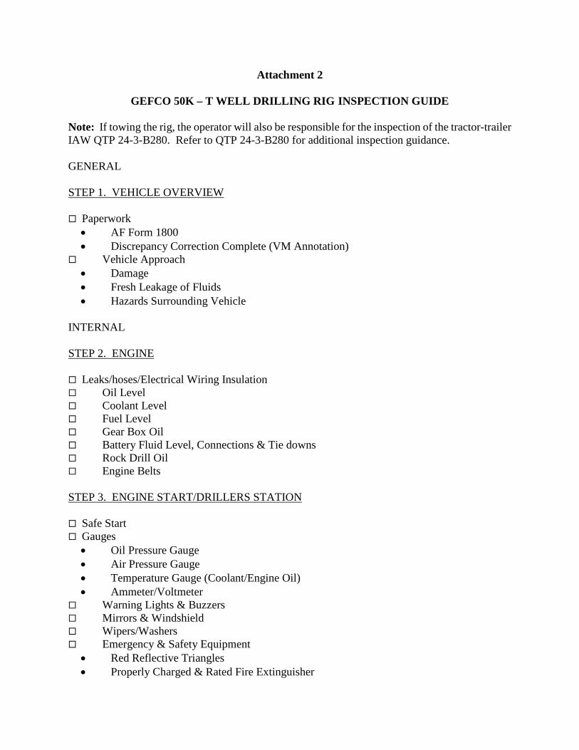
Attachment 2
GEFCO 50K – T WELL DRILLING RIG INSPECTION GUIDE
Note: If towing the rig, the operator will also be responsible for the inspection of the tractor-trailer IAW QTP 24-3-B280. Refer to QTP 24-3-B280 for additional inspection guidance. GENERAL STEP 1. VEHICLE OVERVIEW Paperwork
• AF Form 1800 • Discrepancy Correction Complete (VM Annotation)
Vehicle Approach • Damage • Fresh Leakage of Fluids • Hazards Surrounding Vehicle
INTERNAL STEP 2. ENGINE Leaks/hoses/Electrical Wiring Insulation Oil Level Coolant Level Fuel Level Gear Box Oil Battery Fluid Level, Connections & Tie downs Rock Drill Oil Engine Belts STEP 3. ENGINE START/DRILLERS STATION Safe Start Gauges
• Oil Pressure Gauge • Air Pressure Gauge • Temperature Gauge (Coolant/Engine Oil) • Ammeter/Voltmeter
Warning Lights & Buzzers Mirrors & Windshield Wipers/Washers Emergency & Safety Equipment
• Red Reflective Triangles • Properly Charged & Rated Fire Extinguisher

• Optional (Chains, Emergency Phone List) 3B – Lights/Reflectors/Reflector Tape Condition (Front/Sides/Rear) (When connected to tractor for transport:)
• Left Turn Signal • Right Turn Signal • Taillights • Backing Lights • Brake Lights • Red Reflectors & Amber Reflectors • Reflective Tape Condition
Brakes • Parking Brake Check • Hydraulic Brake Check • Air Brake Check • Service Brake Check
STEP 4. WALK-AROUND INSPECTION 4A - Steering 4B – Suspension
• Airbags • Mounts • Shock Absorbers
4C – Brakes • Brake Chambers • Brake Hoses/Lines • Drum Brake • Brake Linings
4D – Wheels • Rims • Tires • Hub Oil Seals/Axle Seals • Lug Nuts
SIDE OF (TRANSPORT) VEHICLE 4E – Doors 4E – Mirrors 4E – Fuel Tank 4E – Frame

SPECIAL EQUIPMENT 4F – Airbags/Outriggers 4G - Mast 4H - Tophead 4I - Mud Pump/Onboard Air Compressor 4J - Mud/Air Control Valve 4K - Table, Winches/Spinner 4L - Single Arm Loader

Figure A2.1. GEFCO 50K – T Well Drilling Rig Inspection Guide.

Attachment 3
SEVEN-STEP INSPECTION PROCESS Figure A3.1. Seven-Step Inspection Process.
Seven-Step Inspection Process Step Procedure 1. Vehicle Overview • Review the AF Form 1800.
o Ensure any discrepancy has been corrected.
o Vehicle Management annotated the discrepancy was completed.
o Approaching the vehicle. o Damage or vehicle leaning to one
side. o Fresh leakage of fluids. o Hazards around vehicle.
2. Check Engine Compartment • Note: Check that the parking brakes are on and/or wheels chocked.
• Check the following: o Engine oil level. o Coolant level in radiator; condition of
hoses. o Fuel tank level. o Battery fluid level, connections and
tie-downs (battery may be located elsewhere).
o Gear box fluid level. o Check belts for tightness and
excessive wear (alternator, water pump, air compressor)--learn how much "give" the belts should have when adjusted right.
o Leaks in the engine compartment (fuel, coolant, oil, power steering fluid, hydraulic fluid, battery fluid).
o Cracked, worn electrical wiring insulation.
3. Start Engine (Get in and Start Engine) • Make sure parking brake is on towing vehicle.
• Start engine; listen for unusual noises.

• If equipped, check the Anti-lock Braking System (ABS) indicator lights. Light on the driller station should come on and then turn-off. If it stays on the ABS is not working properly.
• Look at the gauges. o Oil pressure. Should come up to
normal within seconds after engine is started.
o Engine air supply pressure. Normal air pressure will range between 120 – 140 psi.
o Ammeter and/or voltmeter. Should be in normal range(s).
o Coolant temperature. Should begin gradual rise to normal operating range.
o Engine oil temperature. Should begin gradual rise to normal operating range.
o Warning lights and buzzers. Oil, coolant, charging circuit warning.
• Check Condition of Controls. Check all of the following for looseness, sticking, damage, or improper setting:
o Control levers. o Throttle control. o Torque selector. o Trailer brake. o Lights. • Check emergency equipment. o Check for safety equipment: o Spare electrical fuses. o Three red reflective triangles. o Properly charged and rated fire
extinguisher. Check for optional items such as:
o List of emergency phone numbers Accident reporting kit (packet).
4. Turn-off Engine • Make sure steel is tabled if attached, lower rpm for minimum 3min cooldown, turn-off the engine, and take the key with you.

5. Do Walk-Around Inspection • General. o Walk around and inspect. o Look for damage caused during
operation. • Left front side. o Mud and auxiliary airline
connection. o 5x6 mud pump. o Catwalk • Front. o Fuel tank. • Right side o Onboard air compressor. o Welder/generator. o Catwalk. • Rear. o Drilling station control levers. o Table working parts. o Working platform.
6. Check Signal Lights • Get on driller station. o Turn key to auxiliary, check lights
and gauges for porper function. o Start the engine.
7. Start the Engine and Check Test for Hydraulic Leaks
• Test for hydraulic leaks. o Move hydraulic driven parts. o Inspect during-operation. • Check rig operation regularly. o Instruments. o Air pressure gauge. Temperature
gauges. o Pressure gauges. o Ammeter/voltmeter. o Tires. • Document any discrepancy on AF
Form 1800. Sign-off AF Form 1800 to signify accomplishment of inspection.