gate – 2016 - career launchermedia.careerlauncher.com/gate-exams/gate actual paper-...
TRANSCRIPT

GENERAL APTI TUDE (GA) (Q.1 – 5) : Car r y One M ar k Each
1. The chai r man r equest ed t he aggr i evedshareholders to _________ him.
(a) bare with (b) bore with
(c) bear with (d) bare
2. I dent i fy t he cor rect spel l ing out of the givenopt ions :
(a) Managable (b) Manageable
(c) Mangaeble (d) Managible
3. Pick the odd one out in the fol lowing :
13, 23, 33, 43, 53
(a) 23 (b) 33
(c) 43 (d) 53
4. R2D2 is a robot . R2D2 can repair aeroplanes. Noother robot can repair aeroplanes. Which of thefollowing can be logical ly infer red from the abovestatements?
(a) R2D2 i s a r obot wh i ch can on l y r epai raeroplanes.
(b) R2D2 is t he only r obot which can r epai raeroplanes.
(c) R2D2 i s a r obot wh i ch can r epai r on l yaeroplanes.
(d) Only R2D2 is a robot .
5. I f 9 6 3,y then 2 43y
y is ________.
(a) 0 (b)13
(c)13
(d) Undefined
(Q.6 – 10) : Car r y Tw o M ar k s Each
6. The fol lowing graph represents the instal ledcapacity for cement production (in tonnes) and theactual production (in tonnes) of nine cement plantsof a cement company. Capacity utilization of a plantis defined as ratio of actual product ion of cement toinstalled capacity. A plant with installed capacityof at least 200 tonnes is called a large plant and aplant with lesser capacity is called a small plant.The difference between total product ion of largeplants and small plants, in tonnes is ________.
300
250
200
150
100
50
01 2 3 4 5 6 7 8 9
Plant Number
Instal led Capacity Actual Product ion
220
160180
150
190
160
200190
160
120
150 140
100120
250230
200190
Cap
acit
y/pr
odu
ctio
n(t
onn
es)
I NSTRUCTI ONS1. Total of 65 quest ions car rying 100 marks, out of which 10 quest ions car rying a total of 15 marks are in
General Apt i tude (GA)2. The Engineer ing Mathemat ics wi l l car ry around 15% of t he t ot al mar k s, the General Apt i tude sect ion
wil l car ry 15% of t he t ot al mar k s and the r emai n i ng 70% of t he t ot al mar k s.3. Types of Quest i ons
(a ) M u l t i p le Choi ce Quest i ons (M CQ) car rying 1 or 2 marks each in al l papers and sect ions. Thesequest ions are object ive in nature, and each will have a choice of four opt ions, out of which the candidatehas to mark the cor rect answer(s).
(b) Numer i cal Answ er Quest i ons of 1 or 2 marks each in al l papers and sect ions. For these quest ionsthe answer is a real number, to be entered by the candidate using the vir tual keypad. No choices wil lbe shown for these type of quest ions.
4. For 1-mar k mult iple-choice quest ions, 1/3 mar k s wil l be deducted for a wrong answer. L ikewise, for 2-mar k s mult iple-choice quest ions, 2/3 marks wil l be deducted for a wrong answer. There is no negat ivemarking for numer ical answer type quest ions.
GATE – 2016EE : EL ECTRI CAL ENGI NEERI NG
Set - 2No. of Quest i ons : 65 Maxi mum Mar k s : 100

2 SOLVED PAPER – 2016 (SET - 2)
7. A pol l of st udents appear ing for mast er s i nengineer ing indicated that 60% of the studentsbel i eved t hat mechani cal engi neer i ng i s aprofession unsui table for women. A researchstudy on women with masters or higher degreesin mechanical engineer ing found that 99% of suchwomen were successful in their professions.
Which of the fol lowing can be logical ly infer redfrom the above paragraph?
(a) Many students have misconcept ions regardingvar ious engineer ing discipl ines.
(b) Men wi th advanced degrees in mechanicalengineer ing bel ieve women are well suited tobe mechanical engineers.
(c) Mechanical engineer ing is a profession wellsui ted for women wi th master s or higherdegrees in mechanical engineer ing.
(d) The number of women pur sui ng h i gherdegr ees i n mechan i cal engi neer i ng i ssmall .
8. Sour ya commi t t ee had pr oposed t heestabl ishment of Sourya Inst itutes of Technology(SITs) in l ine with Indian Inst i tutes of Technology(I ITs) to cater to the technological and industr ialneeds of a developing country.
Which of the fol lowing can be logical ly infer redfrom the above sentence?
Based on the proposal,
(i ) I n the ini t ial years, SI T students wi l l getdegrees from I IT.
(i i ) SITs wil l have a dist inct nat ional object ive.
(i i i )SIT l ike inst i tut ions can only be establ ishedin consulat ion with I IT.
(i v) SI Ts wi l l ser ve t echnological needs of adeveloping country.
(a) (i i i ) and (i v) only
(b) (i ) and (i v) only
(c) (i i ) and (i v) only
(d) (i i ) and (i i i ) only
9. Shaqui l le O’ Neal is a 60% career fr ee throwshooter, meaning that he successful ly makes 60free throws out of 100 at tempts on average. Whatis the probabi l i ty that he wil l successful ly makeexact ly 6 free throws in 10 at tempts?
(a) 0.2508 (b) 0.2816
(c) 0.2934 (d) 0.6000
10. The numeral in the units posit ion of
211870 + 146127 3424 is _________.
TECH NI CAL SECTI ON(Q.1 – 25) : Car r y One M ar k Each
1. The output expression for the Karnaugh mapshown below is
BC
A
0
00
1
01
0
11
0
10
1
1 1 1 1 1
(a) A B (b) A C
(c) A C (d) A C2. The circuit shown below is an example of a
+–
R2
R1
V in
+15V
C
Vout
– 15V
(a) low pass fi l ter (b) band pass fi l ter
(c) high pass fi l ter (d) notch fi l ter
3. The fol lowing figure shows the connect ion of anideal t r ansformer wi th pr imary to secondaryturns rat io of 1 : 100. The appl ied pr imary voltageis 100 V (rms), 50 Hz, AC. The rms value of thecurrent I , in ampere, is ________.
XL = 10 R = 80
XC = 40 k
1 : 100
I~100 V
4. Consider a causal LTI system character ized by
different ial equat ion ( ) 1
( ) 3 ( ).6
dy ty t x t
dt The
r esponse of t he syst em t o t he i npu t
3( ) 3 ( ),t
x t e u t
where u(t) denotes the unit step
funct ion, is
(a) 39 ( )t
e u t
(b) 69 ( )t
e u t
(c) 3 69 ( ) 6 ( )t t
e u t e u t
(d) 6 354 ( ) 54 ( )t t
e u t e u t

SOLVED PAPER – 2016 (SET - 2) 3
5. Suppose the maximum frequency in a band-l imited signal x(t) is 5 kHz. Then, the maximumfr equency i n x(t ) cos (2000 t ), i n k H z, i s______.
6. Consider the funct ion f(z) = z + z* where z is acomplex var iable and z* denotes i t s complexconjugate. Which one of the fol lowing is t rue?
(a) f(z) is both cont inuous and analyt ic
(b) f(z) is cont inuous but not analyt ic
(c) f(z) is is not cont inuous but is analyt ic
(d) f(z) is neither cont inuous nor analyt ic
7. A 3 3 matr ix P is such that , P3 = P. Then theeigenvalues of P are
(a) 1, 1, – 1
(b) 1, 0.5 + j 0.866, 0.5 – j 0.866
(c) 1, – 0.5 + j 0.866, – 0.5 – j 0.866
(d) 0, 1, – 1
8. The solut ion of the different ial equat ion, for t > 0,y(t) + 2y(t) + y(t) = 0 wi th ini t ial condit ionsy(0) = 0 and y(0) = 1, is (u(t) denotes the unitstep funct ion),
(a) te– tu(t)
(b) (e– t – te– t)u(t)
(c) (– e– t – te– t)u(t)
(d) e– tu(t)
9. The value of the l ine integral
2 2
C
2 2xy dx x ydy dz along a path joining the or igin (0, 0, 0) and thepoint (1, 1, 1) is
(a) 0 (b) 2
(c) 4 (d) 6
10. Let f(x) be a real , per iodic funct ion sat isfyingf(– x) = – f(x). The general form of its Four ier seriesrepresentat ion would be
(a) 0 1( ) cos( )kk
f x a a kx
(b)1
( ) sin( )kkf x b kx
(c) 0 21( ) cos( )kk
f x a a kx
(d) 2 11( ) sin(2 1)kk
f x a k x
11. A resistance and a coi l are connected in ser iesand suppl ied from a single phase, 100 V, 50 Hz acsource as shown in the figure below. The rmsvalues of plausible voltages across the resistance(VR) and coi l (VC) respect ively, in volts, are
~ VS VC
VR
(a) 65, 35 (b) 50, 50
(c) 60, 90 (d) 60, 80
12. The voltage (V) and cur rent (A) across a load areas fol lows.
V(t) = 100 sin (t)
i (t) = 10 sin (t – 60) + 2 sin (3t) + 5 sin (5 t).
The average power consumed by the load, in W,is __________.
13. A power system with two generators is shown inthe figure below. The system (generators, busesand t r ansmi ssi on l i nes) i s pr ot ect ed by si xovercurrent relays R1 to R6. Assuming a mix ofdi r ect i onal and nondi r ect i onal r el ays atappropr iate locat ions, the remote backup relaysfor R4 are
~ ~S1
R1 R2
R3 R4
R5 R6
S2
(a) R1 · R2 (b) R2 · R6
(c) R2 · R5 (d) R1 · R6
14. A power syst em has 100 buses i ncl udi ng10 generator buses. For the load flow analysisusi ng N ewt on -Raphson met hod i n pol arcoordinates, the size of the Jacobian is
(a) 189 189 (b) 100 100
(c) 90 90 (d) 180 180
15. The inductance and capacitance of 400 kV, three-phase, 50 H z lossless t r ansmission l i ne ar e1.6 mH /k m/phase and 10 nF /k m/phaser espect i vel y. The sendi ng end vol t age i smaintained at 400 kV. To maintain a voltage of400 kV at the receiving end, when the l ine isdel iver ing 300 MW load, the shunt compensat ionrequired is
(a) capacit ive
(b) induct ive
(c) resist ive
(d) zero

4 SOLVED PAPER – 2016 (SET - 2)
16. A par al l el pl at e capaci t or f i l l ed w i t h t wodielect r ics is shown in the figure below. I f theelectr ic field in the region A is 4 kV/cm, the electr icfield in the region B, in kV/cm, is
Ar = 1
Br = 4 2 cm
(a) 1
(b) 2
(c) 4
(d) 16
17. A 50 MVA, 10 kV, 50 Hz, star-connected, unloadedt hr ee-phase al t er nat or has a synchr onousreactance of 1 p.u. and a sub-t ransient reactanceof 0.2 p.u. I f a 3-phase shor t circuit occurs closeto the generator terminals, the rat io of init ial andfinal values of the sinusoidal component of theshor t circuit cur rent is __________.
18. Consider a l inear t ime-invar iant system wi tht ransfer funct ion
H(s) = 1
1s
I f t he i nput i s cos (t ) and t he st eady st at eoutput is A cos (t + ), then the value of A is_________.
19. A three-phase diode br idge rect i fier is feeding aconstant DC current of 100 A to a highly induct iveload. I f three-phase, 415 V, 50 Hz AC source issupplying to this br idge rect i fier then the rmsvalue of the cur rent in each diode, in ampere,is _________.
20. A buck-boost DC-DC conver ter, shown in t hefigure below, is used to conver t 24 V bat teryvoltage to 36 V DC voltage to feed a load of 72 W.I t is operated at 20 kHz with an inductor of 2 mHand output capacitor of 1000 F. Al l devices areconsidered to be ideal. The peak voltage acrossthe sol id-state switch (S), in volt , is _________.
+
– +
–24 V
2 mH
SLoad
36 V
21. For the network shown in the figure below, thefrequency (in rad/s) at which the maximum phaselag occurs is, __________.
9
V in V0
1
1F
22. The di r ect i on of r ot at i on of a si ngl e-phasecapacitor run induct ion motor is reversed by
(a) interchanging the terminals of the AC supply.
(b) interchanging the terminals of the capacitor.
(c) interchanging the terminals of the auxi l iarywinding.
(d) i n t er changi ng t he t er mi nals of bot h t hewindings.
23. I n t he ci r cui t shown below, t he vol t age andcurrent sources are ideal. The voltage (Vout) acrossthe cur rent source, in volts, is
+–
2
10V 5A Vout
+
–
(a) 0 (b) 5
(c) 10 (d) 20
24. The graph associated with an elect r ical networkhas 7 branches and 5 nodes. The number ofindependent KCL equat ions and the number ofindependent KVL equat ions, respect ively, are
(a) 2 and 5 (b) 5 and 2
(c) 3 and 4 (d) 4 and 3
25. Two elect rodes, whose cross-sect ional view isshown in t he f i gur e below, ar e at t he samepotent ial . The maximum elect r ic field wi l l be atthe point
A C
B
D
(a) A (b) B
(c) C (d) D

SOLVED PAPER – 2016 (SET - 2) 5
(Q.26 – 55) : Car r y Tw o M ar k s Each
26. The Boolean expression a b c d b c simpli fies is
(a) 1 (b) ab
(c) a, b (d) 0
27. For the circuit shown below, taking the opampas ideal, the output voltage Vout in terms of theinput voltages V1, V2 and V3 is
+
–V3
V2
V1
1
1
1
VCC
9
Vout
– VSS
(a) 1.8V1 + 7.2V2 – V3
(b) 2V1 + 8V2 – 9V3
(c) 7.2V1 + 1.8V2 – V3
(d) 8V1 + 2V2 – 9V3
28. Let x1(t) X1() and x2(t) X2() be two signalswhose Four ier Transforms are as shown in thefigure below. I n the figure, h(t) = 2 te denotesthe impulse response.
X1() X2()
– B1– B1 B1 B12 2
– B2 B2
X1(t)
X2(t)
y(t)h t = e( ) – 2 t
For t he syst em shown above, t he minimumsampl ing rate required to sample y(t), so thaty(t ) can be uniquel y r econst r uct ed f r om i t ssamples, is
(a) 2B1 (b) 2(B1 + B2)
(c) 4(B1 + B2) (d)
29. The value of the integral sin 22
tdt
t
is equal
to(a) 0 (b) 0.5
(c) 1 (d) 2
30. L et y(x) be t he sol ut i on of t he di f fer ent i al
equat i on 2
24 4 0
d y dyy
dxdx w i t h i n i t i al
condit ions y(0) = 0 and 0
1.x
dydx
Then the value
of y(1) is _____.
31. The l ine integral of the vector field
2 2ˆF 5 3 2xzi x y j x zk
al ong a pat h f r om (0, 0, 0) t o (1, 1, 1)parameter ized by (t, t2, t) is _________.
32. Let P = 3 1
1 3
. Consider the set S of al l vectors
x
y
such that a2 + b2 = 1 where a
b
= P .x
y
Then S is
(a) a circle of radius 10
(b) a circle of radius 1
10
(c) an el l ipse with major axis along 11
(d) an el l ipse with minor axis along 1
1
33. Let the probabi l i ty density funct ion of a randomvar iable, X, be given as :
3 43( ) ( ) ( )
2x x
xf x e u x ae u x
where u(x) is the unit step funct ion.
Then the value of ‘a’ and Prob {X 0}, respect ively,are
(a) 12,
2(b) 1
4,2
(c) 12,
4(d) 1
4,4
34. The dr iving point input impedance seen fromthe source VS of the circuit shown below, in ,is _______.
+–
V1
I S 2
3
2
4VS
+ –

6 SOLVED PAPER – 2016 (SET - 2)
35. The z-parameters of the two por t network shownin the figure are z11 = 40 , z12 = 60 , z21 = 80 and z22 = 100 . The average power del ivered toRL = 20 , in wat ts, is _______.
+–
I 1 I 210
+
–
V2V1
+
–
20 V [Z] RL
36. I n the balanced 3-phase, 50 Hz, ci rcuit shownbelow, the value of inductance (L) is 10 mH. Thevalue of the capacitance (C) for which al l the l inecurrents are zero, in mil l i farads, is _______.
L LC
CC
37. I n the circuit shown below, the ini t ial capacitorvol t age i s 4 V. Swi t ch S1 i s closed at t = 0.The charge (in C) lost by the capaci tor fromt = 25 s to t = 100 s is ______.
4V
5 F5
S1
38. The single line diagram of a balanced power systemis shown in the figure. The voltage magnitude atthe generator internal bus is constant and 1.0 p.u.The p.u. reactances of different components in thesystem are also shown in the figure. The infini tebus voltage magnitude is 1.0 p.u. A three phasefault occurs at the middle of l ine 2. The rat io ofthe maximum real power that can be t ransfer reddur ing the pre-fault condit ion to the maximumreal power that can be t ransfer red under thefaulted condit ion is _______.
~
Generatorinternal bas j0.1
j0.2j0.5
L ine 1
j0.5
L ine 2
j0.1
I nfini te bus
39. The open l oop t r ansfer funct i on of a uni t yfeedback control system is given by
K ( 1)
G( ) ,K 0,T 01 T 1 2
ss
s s s
The closed loop system wil l be stable i f,
(a) 4 K 1
0 TK 1
(b) 4 T 2
0 KT 2
(c)T 2
0 KT 2
(d) 8 K 1
0 TK 1
40. At no load condit ion, a 3-phase, 50 Hz, lossless
power t ransmission l ine has sending-end andreceiving-end vol tages of 400 kV and 420 kVrespect ively. Assuming the velocity of t ravel ingwave to be the velocity of l ight , the length of thel ine, in km, is __________.
41. The power consumption of an industry is 500 kVA,at 0.8 p.f. lagging. A synchronous motor is addedto raise the power factor of the industry to unity.I f the power intake of the motor is 100 kW, thep.f. of the motor is _________.
42. The flux l inkage () and cur rent (i ) relat ion for
an elect romagnet ic system is = .
i
g When
i = 2A and g (ai r -gap l engt h) = 10 cm, t hemagni tude of mechanical force on the movingpar t , in N, is _________.
43. The start ing l ine current of a 415 V, 3-phase, deltaconnected induct ion motor is 120 A, when therated voltage is applied to i ts stator winding. Thestar t ing l ine current at a reduced voltage of 110 V,in ampere, is _________.
44. A single-phase, 2 kVA, 100/200 V t ransformer isreconnected as an auto-t ransformer such that i tskVA rat ing is maximum. The new rat ing, in kVA,is _______.
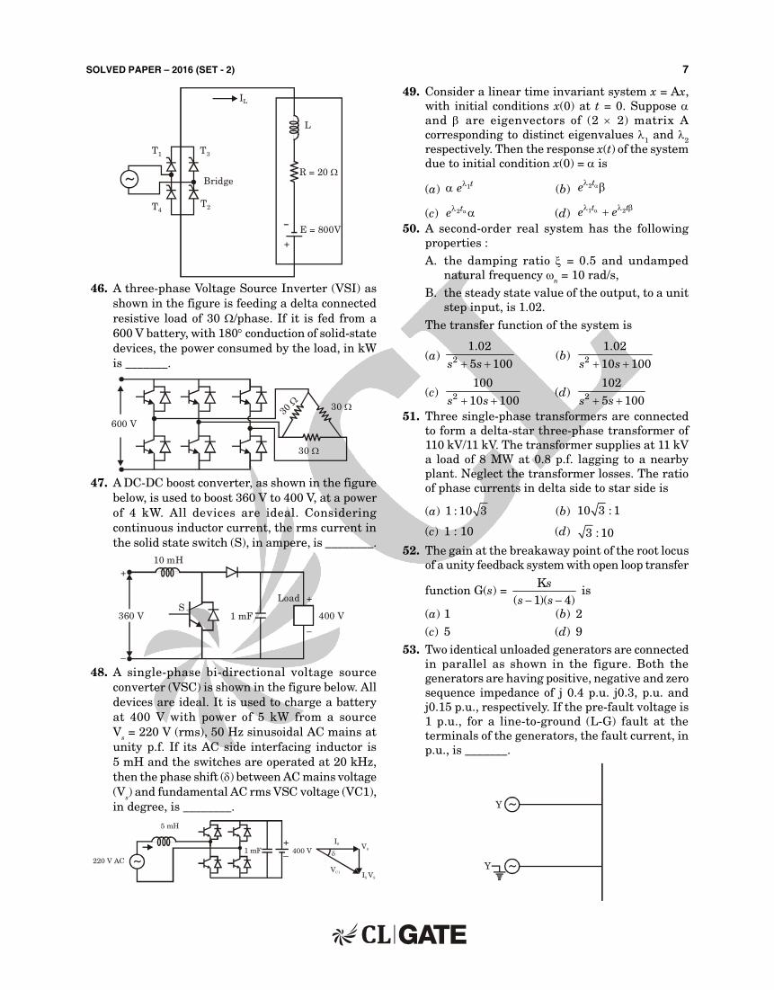
45. A ful l-br idge conver ter supplying an RLE load isshown in figure. The fir ing angle of the br idgeconver ter is 120. The supply voltage vm(t) = 200 sin (100 t) V, R = 20 , E = 800 V. The inductorL is large enough to make the output cur rent I L asmooth dc cur rent. Switches are lossless. The realpower feedback to the source, in kW, is _____.
SOLVED PAPER – 2016 (SET - 2) 7
~
I L
T3T1
T4T2
Br idge
L
R = 20
E = 800V–
+
46. A three-phase Voltage Source Inver ter (VSI ) asshown in the figure is feeding a delta connectedresist ive load of 30 /phase. I f i t is fed from a600 V bat tery, with 180 conduct ion of sol id-statedevices, the power consumed by the load, in kWis _______.
600 V
30
30
30
47. A DC-DC boost conver ter, as shown in the figurebelow, is used to boost 360 V to 400 V, at a powerof 4 kW. Al l devices ar e ideal . Consi der i ngcont inuous inductor cur rent , the rms cur rent inthe sol id state switch (S), in ampere, is ________.
10 mH
1 mF
Load
400 V360 VS
+
–
+
–
48. A single-phase bi -di r ect ional vol t age sour ceconver ter (VSC) is shown in the figure below. Al ldevices are ideal. I t is used to charge a bat teryat 400 V wi th power of 5 kW fr om a sour ceVs = 220 V (rms), 50 Hz sinusoidal AC mains atunity p.f. I f i ts AC side inter facing inductor is5 mH and the switches are operated at 20 kHz,then the phase shift () between AC mains voltage(Vs) and fundamental AC rms VSC voltage (VC1),in degree, is ________.
~
5 mH
220 V AC1 mF 400 V
+–
VS
VSI S
VC1
I S
49. Consider a l inear t ime invar iant system x = Ax,with ini t ial condit ions x(0) at t = 0. Suppose and ar e eigenvect or s of (2 2) mat r i x Acorresponding to dist inct eigenvalues 1 and 2
respect ively. Then the response x(t) of the systemdue to ini t ial condit ion x(0) = is
(a) 1te (b) 2te
(c) 2te (d) 1 2t te e 50. A second-order real system has the fol lowing
proper t ies :A. the damping rat io = 0.5 and undamped
natural frequency n = 10 rad/s,B. the steady state value of the output , to a unit
step input , is 1.02.
The t ransfer funct ion of the system is
(a) 2
1.02
5 100s s (b) 2
1.02
10 100s s
(c) 2
100
10 100s s (d) 2
102
5 100s s 51. Three single-phase t ransformers are connected
to form a delta-star three-phase t ransformer of110 kV/11 kV. The t ransformer suppl ies at 11 kVa load of 8 MW at 0.8 p.f. lagging to a nearbyplant . Neglect the t ransformer losses. The rat ioof phase cur rents in delta side to star side is
(a) 1 : 10 3 (b) 10 3 : 1
(c) 1 : 10 (d) 3 : 1052. The gain at the breakaway point of the root locus
of a unity feedback system with open loop transfer
funct ion G(s) = K
( 1)( 4)s
s s is
(a) 1 (b) 2(c) 5 (d) 9
53. Two ident ical unloaded generators are connectedin paral lel as shown in t he f igure. Both thegenerators are having posit ive, negat ive and zerosequence impedance of j 0.4 p.u. j0.3, p.u. andj0.15 p.u., respect ively. I f the pre-fault voltage is1 p.u., for a l ine-to-ground (L -G) faul t at theterminals of the generators, the fault cur rent , inp.u., is _______.
~
~
Y
Y

8 SOLVED PAPER – 2016 (SET - 2)
ANSWERSGener al Apt i t ude (GA)
1. (c) 2. (b) 3. (b) 4. (b) 5. (c) 6. (120) 7. (a) 8. (c)
9. (a) 10. (7)
Techn i cal Sect i on
1. (b) 2. (a) 3. (10) 4. (d) 5. (6) 6. (b) 7. (d) 8. (a)
9. (b) 10. (b) 11. (d) 12. (250) 13. (d) 14. (a) 15. (b) 16. (c)
17. (5.0) 18. (0.707) 19. (57.7) 20. (60) 21. (0.316) 22. (c) 23. (d) 24. (d)
25. (c) 26. (d) 27. (d) 28. (b) 29. (d) 30. (7.38) 31. (4.41) 32. (c)
33. (a) 34. (20) 35. (35.55) 36. (3.03) 37. (6.99) 38. (2.4) 39. (c) 40. (294.59)
41. (0.3162) 42. (141.4) 43. (31.807) 44. (6) 45. (6) 46. (24) 47. (3.5) 48. (9.21)
49. (a) 50. (b) 51. (a) 52. (a) 53. (6) 54. (2) 55. (9.55)
54. An energy meter, having meter constant of 1200r evol u t i ons/k Wh, mak es 20 r evol u t i ons i n30 seconds for a constant load. The load, in kW,is _______
55. A rotat ing conductor of 1 m length is placed in aradial ly outward (about the z-axis) magnet ic fluxdensity (B) of 1 Tesla as shown in figure below.Conductor is paral lel to and at 1 m distance fromthe z-axis. The speed of the conductor in r.p.m.requi red to induce a vol tage of 1 V across i t ,should be _______.
Z
B
1m
1m

SOLVED PAPER – 2016 (SET - 2) 9
EXPL ANATI ONSGener al Apt i t ude (GA)
3. The given number 33 is odd one out , because theremaining numbers are pr ime number.
5. Given, 9 6y = 3
I t has two values either
(9y – 6) = 3 ...(i )
Or – (9y – 6) = 3
9y – 6 = – 3 ...(i i )
From equat ion (i ),
9y = 9
y = 1
Or from equat ion (i i ),
9y = 3
y = 13
Now y2 = 43y
put y = 1,
we get = 4
13
= 13
and also put y = 13
we get ,1 49 9 =
3 19 3
So, the required value is 1 .
3
6. From the given graph large plants which arehaving instal led capacity of at least 200 tonnesare 1, 4, 8 and 9.
So, the total product ion of large plants
= 160 + 190 + 230 + 190
= 770
Now the remaining plants with instal led capacityis less then 200 tonnes are 2, 3, 5, 6 and 7.
So, total product ion of small plants
= 150 + 160 + 120 + 100 + 120
= 650
Then difference= 770 – 650
= 120
9. The quest ion clear ly explains that shaqui l lemakes 60 free throws out of 100
Hence, Probabil i ty of free throw = 60
0.6100
And probabi l i ty of NOT free throw
= 1 – 0.6 = 0.4
So required probabi l i ty of exact ly 6 throws in10 at tempts wil l be given by
10C6 0.66 0.44 = 0.2508
10. Unit digit of 211870 + 146127 3424 is 1 + 6 1 = 7
Techn i cal Sect i on
1. BCA
0
1
1
1
0
1
0
1
1
1
00 01 11 10
A
A
B C B C B C B C
The common factor s among the combinat ionto-make a count of 4 is A and C
Hence, F = A C
2.
Vout
V in
R1
R2
C
out
in
VV
= 2 2
1
1 1R R
C CR
j j
out
in
VV
=
2 2
1
R R C 1C C
Rj j
out
in
VV
= 2
1 2
RR R C 1j
So the system is a low pass fi l ter.
3. The above circuit can be drown by t ransfer r ingsecondary circuit to pr imary side.
100 V
10 j
I 80000
(100)2
40000
(100)2
j–
I rms = 100
8 10 4j j
= 100
8 6 j=
2 2
100
8 6=
10010
= 10
So, I rms = 10 A

10 SOLVED PAPER – 2016 (SET - 2)
4. The different ial equat ion( ) 1
( )6
dy ty t
dt = 3x(t)
So, 1Y( ) Y( )
6s s s = 3X(s)
1Y( )
6s s
= 3X(s)
Y(s) = 3X( )
16
s
s
X(s) = 913
s
So, Y(s) = 91 13 6
s s
= 54 541 16 3
s s
So, y(t) = 1 6 1 354 54 ( )t te e u t
5. As the maximum frequency in a band-l imi tedsignal x(t) is 5 kHz then the maximum frequencyin x(t) cos (200 t) is 6 kHz.
6. Here the given funct ionf(z) = z + z*
where z = complex var iablef(z) = 2x is cont inuous (polynomial)
u = 2xv = 0
ux = 2uy = 0
vx = 0vy = 0
C.R. equat ion is not sat isfied,Hence there is no analyt ic is f(z) is cont inuousbut not analyt ic.
7. According to Calyey Hamilton theorem3 = = 0, 1, – 1
So, the eigen values of are 0, 1, – 1.8. The different ial equat ion is
y(t) + 2y(t) + y(t) = 0
2Y( ) (0) (0) 2 Y( ) (0) Y( )s s sy y s s y s = 0
Y(s) = 2
(0) (0) 2 (0)
2 1
sy y y
s s
Given that y(0) = 1,y(0) = 0
Hence Y(s) = 2
1
1s
y(t) = ( )tte u t
9. Let I = C
F drwhere F = 2 22xy i x yj k
Now F = 0(F is ir rotat ional F is conservat ive)
F = ( is scalar potat ional funct ion)
x = 2xy2
y = 2x2yz = 1
= x2y2 + z + Cwhere, F is conservat ive
C
F.dr =
(1,1,1)(1,1,1)2 2
(0,0,0)(0,0,0)
d x y z = 2
10. As given, per iodic funct ion sat isfyingf(– x) = – f(x)
So funct ion is an odd funct ion.Hence the Fourier series will have sine term only so
f(x) = 1
sin( )xk
b kx
11. As Vs = 100 V, and the vector sum of VR and VC
should be equal to Vs i .e.
Vs = 2 2R CV V
then we get , VR = 60 VVC = 80 V
Hence the rms values of plausible voltages acrossthe resistance VR and coi l VC is 60 V and 80 V.
12. There are 2 methods to solve this quest ion :
M et hod 1 :From quest ion,The average power consumed by the load
= P = V II 1 cos 1
= 100 10
cos60 250W2 2
Since V1 = 01
V2
I 1 = 01
I2

SOLVED PAPER – 2016 (SET - 2) 11
M et hod 2 :V(t) = 100 sin (t)
i(t) = 10 sin (t – 60) + 2 sin (3 t) + 5 sin (5 t)P = V(t) i (t)
= 1000 sin t · sin (t – 60) + 200 sin t· sin 3 t + 500 sin t sin 5 t
= 500 [cos (t – t + 60) – cos (t + t – 60)] + 100 [cos (t – 3t) – cos (t
+ 3t] + 250 [cos (t – 5t)– cos (t + 500 t)]
= 500 [cos 60 – cos (2t – 60)]+ 100 [(cos (– 2t) – cos 4t)]
+ 250 [cos (– 4 t) – cos (6 t)]= 500 cos 60= 250 W
So, the average value of cos (2t – 60), cos (2t),cos (4 t), cos (6 t) i l l be zero.
14. Size of the Jacobian matr ix= 2n – m – 1 2n – m – 1
where n = number of busesm = number of generator buses
As given there are 10 generator buses, so we needto assume one bus within the 10 buses as slackbusthen (2 100 – 10 – 1) (2 100 – 10 – 1)
= 189 18915. As we know that
Zn = LC
= 3
91.6 1010 10
= 400
SIL = 400 400
400
= 400 MW
I n t he second case SI L decr eases means Zn
increases.
Zn increases with increase in inductance ‘L’.
So, i t is induct ive.
16. Since voltage is same across both the regions anddistance between two plates is also same, theelect r ic f ield r emains same thr oughout bothregion.
As we know E = Vd
= constant for both regions.
Where E = Elect r ic field
V = Potent ial di fference accross the capacitor
d = Separator along a paral lel plate capacitor
17. I = E
Xg
d
I = E
Xg
I 1X d
I 1X
II
= X 1.0
0.2X d
= 10 52 1
Hence, the rat io of ini t ial and final values of thesinusoidal component of the short circuit cur rentsis 5 : 1.
18. H(s) = 1
1s
Put s = j, H(j) = 1
1j
H( )j = 2
1
1
input x(t) = cos (t)
Here = 1 rad/sec
and ( )x t = 1
Hence, steady state output
y(t) = 1( ) H( ) cos H( )x t j t j
A = 1
( ) H ( )x t j
A = 1
2 = 0.707
So, the value of A is 0.707.
19. Each diode conducts for 120 for one completecycle in the 3- diode br idge rect i fier
I D rms =
2 320
0
1I
2d t
= 02
I2 3
= 0I
3
= 100
3= 57.7 A

12 SOLVED PAPER – 2016 (SET - 2)
20. From the given figure when switch ‘S’ is off, diodeD is on.
Hence,
+
– +
–24 V 36 V
Peak voltage across switch
= 24V + 36V = 60V
21. From the figure we assume
R1 = 9
R2 = 1
Hence, i t can be wr it ten as :
o
in
V ( )V ( )
ss
= 2
1 2
1R
C1
R RC
s
s
=
2
1 2
1 R C1 R R C
ss
= 2
1 22
2
1 R C
R R1 R C
R
s
s
Let R2C = T
1 2
2
R RR
=
Hence o
in
V ( )V ( )
ss
= 1 T
1 Tss
This represents a lag compensator
T = R2C = 1.1 = 1 sec
= 1 9
101
Maximum phase lag occurs at frequency
n = 1
T =
1
1 10
Hence, n = 0.316 rad/sec
22. I nter changing the terminals of the auxi l iarywinding.
23. From the given circuit diagram,
+–
2
5 A
10 V 5 A Vout
+
–
Hence Vout = (5 2) + 10 = 20 VSo, the voltage (Vout) across the cur rent source is20 V.
24. As per the input required,Number of KCL equat ion = n – 1 = 5 – 1 = 4Number of KVL equat ion
= b – (n – 1) = 7 – (5 – 1) = 3
(Here b = no. of branches, n = no. of nodes)Hence 4 and 3.
25. From the figure, we can see that at the point C,E (elect r ic field intensity) is maximum beingclosest to the other plate.
A D C
BHence the maximum elect r ic f ield wi l l be atpoint C.
26. Here the given boolean expression is
F = a b c d b c
= a b c d b c
= a b c d b c (Apply Demorgan's Theorems)
= a b c d b c Since c c
= a b c d b c Since 0
0
b b
c c
F = 0
27. From the circuit diagram, we can see that
+
–V3
V1
1
1
4
9
VB
VA Vout
V2
VA = 1 24 1
V V5 5
Hence Vout = – 9 V3 + 10 VA
= – 9 V3 + 8 V1 + 2 V2
28. As given
Bandwidth of X1() = B1
Bandwidth of X2() = B2
System has h(t) = 2 te
and input to the system is x1(t) · x2(t)
The bandwidth of x1(t) · x2(t) is B1 + B2.
The bandwidth of output wi l l be B1 + B2.
Hence sampling rate wi l l be 2(B1 + B2).
SOLVED PAPER – 2016 (SET - 2) 13
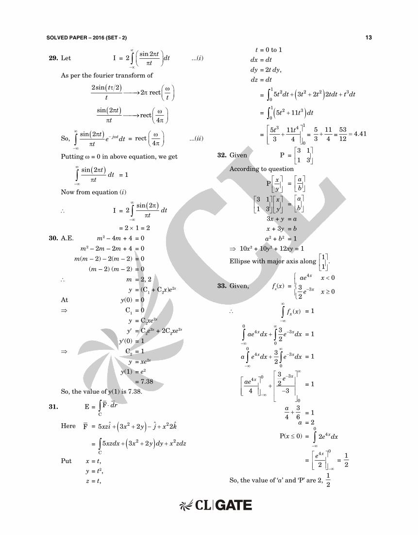
29. Let I = sin 2
2t
dtt
...(i )
As per the four ier t ransform of
2sin 22 rect
t
t t
sin 2rect
4
t
t
So, sin 2 j tte dt
t
= rect4
...(i i )
Put t ing = 0 in above equat ion, we get
sin 2 tdt
t
= 1
Now from equat ion (i )
I = sin 2
2 dtt
= 2 1 = 2
30. A.E. m2 – 4m + 4 = 0
m2 – 2m – 2m + 4 = 0
m(m – 2) – 2(m – 2) = 0
(m – 2) (m – 2) = 0
m = 2, 2
y = (C1 + C2x)e2x
At y(0) = 0
C1 = 0
y = C2xe2x
y = C2e2x + 2C2xe2x
y(0) = 1
C2 = 1
y = xe2x
y(1) = e2
= 7.38
So, the value of y(1) is 7.38.
31. E = C
F drHere F = 2 2 ˆˆ ˆ5 3 2 2xzi x y j x k
= 2 2
C
5 3 2xzdx x y dy x zdz Put x = t,
y = t2,
z = t,
t = 0 to 1
dx = dt
dy = 2t dy,
dz = dt
= 12 2 2 3
05 3 2 2t dt t t tdt t dt
= 12 3
05 11t t dt
=
13 4
0
5 113 4t t
= 5 113 4 =
534.41
12
32. Given P = 3 1
1 3
According to quest ion
Pxy
= ab
3 1
1 3
x
y
= ab
3x + y = a
x + 3y = b
a2 + b2 = 1
10x2 + 10y2 + 12xy = 1
Ell ipse with major axis along 1
.1
33. Given, fx(x) =
4
3
0
30
2
x
x
ae x
e x
( )xf x
= 1
04 3
0
32
x xae dx e dx
= 1
04 3
0
32
x xa e dx e dx
= 1
304
0
32
4 3
xx eae
= 1
34 6a = 1
a = 2
P(x 0) = 0
42 xe dx
= 04
2
xe
= 12
So, the value of ‘a’ and ‘P’ are 2, 12

14 SOLVED PAPER – 2016 (SET - 2)
34. We need to find the impedance seen by VS.
AV1
I S
VS4V1
2
3
2
4
–
–+
+
Zs = VI
s
s
V1 = 2I s
Apply the KCL at node A
I s + 4 V1 = A AV V3 6
VA = Vs – V1
and V1 = 2 I s
So, I s + 8I s = V 2I V 2I
3 6s s s s
54 I s = 2Vs – 4I s + Vs – 2I s
3Vs = 60 I s
VI
s
s= Rs = 20
35. From the given figure
[Z]V1 V2
I 1 I 2
–20 V 20
10
+
+ +
– –
Z11 = 40 ,
Z12 = 60 W,
Z21 = 80 ,
Z22 = 100
Also from the figure
V2 = – 20 I 2 ...(i )
and V1 = 40 I 1 + 60 I 2 ...(i i )
V2 = 80 I 1 + 100 I 2 ...(i i i )
From equat ion (i ) and (i i i ), we have
So, – 20 I 2 = 80 I 1 + 100 I 2
I 2 = 12
I3
...(iv)
Using equat ion (i i ) and (i v), we haveSo, V1 = 40 I 1 + 60 I 2
= 1 12
40I 60 I3
V1 = 0
From the figure,
20 = 10 I 1 + V1
Since, V1 = 0
So, I 1 = 2A
So, I 2 = 4
A3
Power dissipated in
RL = 2
22 L
4I R 20
3
= 16
209 = 35.56 W
So, the average power del ivered is 35.56 W.
36. By using the star to delta conversion
CL
C CL
L L L
L
C/3 C/3C/3
When the paral lel pair of induct ion-capacitor isresonant at f = 50 Hz, l ine cur rent wi l l be zero
So, 50 2 = 1
LC3
100 = 1
LC3
Since, L = 10 mH
(100)2 2 = 3
LC
C = 2 2 3
3
100 10 10
= 3.04 mF
Hence, C wil l be 3.04 mF.
37. From the given diagram,S1
4V5
5 F
i (t) = 45
te
= RC = 25 10– 6 sec

SOLVED PAPER – 2016 (SET - 2) 15
Hence the change lost by capacitor from = 25 sto 100 s is
100 sec
25 sec
( )i t dt
= 6.99 10– 6 C
38. From the quest ion, we see that
The rat io = 1 2
2 1
P XP X
j 0.1 j 0.5
3
2X =2
j 0.2
j 0.2
j 0.1
j 0.5
j 0.5
j 0.6
j 0.3 j 0.3
1
X =1=
(1) 0.3 0.6
1.2j j
j
= j 0.15
(2) 0.3 0.6
1.2j j
j
= j 0.15
(3) 0.3 0.31.2
j jj = j 0.075
1 j 0.35 2
X12
j 0.075
j 0.15
j 0.075
j 0.15j 0.2 j 0.15
X12 = X2
0.35 0.15
0.35 0.150.075
j jj j
j
= j 1.2 p.u.
Hence1
2
PP =
2
1
X 1.2 12X 0.5 5
jj
Hence the rat io of the maximum real power thatcan be t ransfered dur ing the pre-fault condit iont o t he maxi mum r eal power t hat can betransfer red under the fault condit ion 12 : 5.
39. Through open loop t ransfer funct ion
G(s) =
K ( 1), K 0, and T 0
1 T 1 2s
s s s
For closed loop system stabi l i t y, character ist icequat ion is
1 + G(s) H(s) = 0
1 + K ( 1)
11 T 1 2
ss s s
= 0
s(1 + Ts) (1 + 2s) + k(s + 1) = 0
2Ts3 + (2 + T)s2 + (1 + k)s + k = 0
Using Routh's cr i ter ia
3
2
1
0
2T (1 )
(2 T)
2 T 1 2T0
(2 T)
ksk
sk k
s
s k
For stabi l i ty, k > 0
and (2 + T) (1 + k) – 2Tk > 0
k(2 + T – 2T) + (2 + T) > 0
or – (T – 2)k + 2(2 + T) > 0
– k > – 2 T
T 2
or k < T 2T 2
Hence the closed loop system wil l be stable, i f
0 < k < T 2T 2
40. From the quest ion, at no load
Vs = AVR
where VS = sending-end voltage
VR = receiving-end voltage
400 = A 420
A = 400
0.9524420
A = YZ1
2
= L C1
2
r j g j
For lossless l ine r = 0, g = 0
then A = C L
12
l = L C
A = 0.9524 = 2 2
12l
l = 0.3085

16 SOLVED PAPER – 2016 (SET - 2)
= 0.3085
l
Vf
= 2
530 1050 =
20.3085
l
l = 294.74Hence the length of the l ine is 294.74 km.
41. From the quest ion, we see thatP1 = 500 0.8
= 400 kWQ1 = 500 0.6
= 300 k VAR
The power factor is to be raised to unity
The motor has to supply 300 kVAR
The motor rat ing is 100 kW, 300 kVAR
m = 1 Qtan
P
m = 1 300tan
100
= tan – 1 (3) = 71.56
Power factor of motor = cos m = cos 71.56 = 0.316
Hence the power factor of the motor is 0.316.
42. As given in the quest ion the stored energy inelect romagnet ic system
E = 12
i
E = 12
i ig Since
ig
Restor ing force in EM system
F = Ed
dx
Here x = g = air gap length
Now F = 3 2
2
12
i
g
= 3 2
212
ig
= 3 / 21 (2)
2 0.1 0.1
= 141.4 N
So, the magnitude of mechanical force is 141.4 N.
43. Given, 415 V, 3-phase, connected induct ionmotor (I st)l ine = 120A at rated voltage.
at , V = 110 V, i .e. reduced voltage
I st = x(I st)rated
where, x = reduced
rated
VV
x = 110415
(I st)at 110 V = 110
120415
= 31.807 A
So, the star t ing l ine cur rent number is 31.807 A.
44. Given, 2 kVA, 100/200 V t ransformer,
a2 winding = 200
2100
[(kVA)auto]max = (a2 winding + 1) (kVA)2 winding
= (2 + 1) 2 = 6
Hence, the new rat ing is 6 kVA.
45. From the circuit diagram
Vo = V
2 cosm
= 2002 cos120
Vo = – 200 V
Vo = 200 V
Power balance equat ion,
EI o = 2I R V Io o o
800 I o = 2I (20) 200Io o
600 I o = 220 I o
I o = 30 A
Power fed to source = Vo I o
= 200 30 = 6 kW
46. From the above diagram
VL = Vph = 2
V3 s
Vph = 2
6003
P = 2phV
3R
=
223 600
330
= 24 kW
So, the power consumed by the load is 24 kW.
47. From the diagram
T
I s
V tTon
i s

SOLVED PAPER – 2016 (SET - 2) 17
VV
o
s
= 1
1
where Vo = 400 V
Vs = 360 V
400360
= 1
1 = 0.1
Vs I s = Power
360 I s = 4000
I s = 11.1 A
Neglect ing r ipple in i s,
I switch (rms) = 1 2
onTI
Ts
= I 11.1 0.1s
= 3.5 A
Hence, the rms cur rent in the sol id state is 3.5A.
48. Given that ,
I Xs s
I s
Vc1
P = Vs I s p.f. (p.f. = power factor )
5 103 = 220 I s 1
I s = 22.72 A
tan = I XVs s
s
= 3
1 22.72 2 50 5 10tan
220
= tan – 1 (0.16)
= 9.21
So, the phase shift is 9.21.
49. Given l inear t ime invar iant system
x = Ax
Eigne values are 1 and 2
We can wr ite,
(t) = 1
2
0
0
t
t
e
e
Response due to ini t ial condit ions,x(t) = (t) · x(0)
x(t) = 1
2
0
00
t
t
e
e
= 1te
The response x(t) of the system is 1te
50. Damping rat io = 0.5
Undamped natural frequencyn = 10 rad/sec
Steady state output to a unit step input
Css = 1.02
Hence steady state er ror = 1.02 – 1.00
ess = 0.02
Required character ist ics equat ion is,2 22 n ns s = 0
2 2 0.5 10 100s s = 0
2 10 100s s = 0
From opt ions, i f we take opt ion (b)
then Css = 0
l im .C( )s
s s
= 20
1 102l im
10 100ss
s s s
Css = 1.02
H ence t he t r ansfer f unct i on of a syst em
is 2
1.02
10 100s s .
51. Given the t ransformer suppl ies at 11 kV, load is8 MW, 0.8 Pf lagging
Y
V
V
ph
ph
=
YI
I
ph
ph
(I ph) =
YY
VI
V
phph
ph
Y
I
V
ph
ph
=
113 1 : 10 3
110
So, the rat io of phase cur rents in delta side tostar side is 1 : 10 3 .
52. Given, the gain at breakaway point
Open loop t ransfer funct ion
OLTF G(s) = K
( 1)( 4)s
s s
Now, character ist ics equat ion is
1 + G(s) H(s) = 0
K1
( 1)( 4)s
s s
= 0
Ks + (s2 + 5s + 4) = 0
K = 2 5 4s s
s
=
45s
s

18 SOLVED PAPER – 2016 (SET - 2)
For break away point :Kd
ds = 0
Kdds
= 24
1 0 0s
we get s = 2Therefore val id break away point is
s = 2,
Now gain at s = 2 is
K =
Product of distances from al lthe poles to break away pointProduct of distance from al l
the zeros to break away point
Gain, K = 1 2
12
Hence the value of K is 1.
53. From the given quest ion i t is clear which has beengiven below is
From the figure
I a1
~ ~
j 0.4j 0.4
j 0.3j 0.3
j 0.15
j 0.15
1 0++
– –1 0
~ 1 0
j 0.2
j 0.15
+
–
j 0.15
I a1
Fault cur rent ,
I f = 3 I a1
= 3
0.2 0.15 0.15
= 3
0.50I f = 6 p.u.
So, the value of fault cur rent is 6 p.u.
54. From given data
Number of revolut ions = 20
Time required = 305
Meter constant = 1200 rev/kWh
Ploss = 20 36001200 30
= 2 kW
So, the total power loss is 2 kW.
55. From the given quest ion
Voltage induced = 1
0
E Im d(where Em is induced elect r ic field)
= Em · volts
Since voltage induced = 1 V
So, Em = 1 V/m
As we know Em = V B
where V = (radius of path) (angular velocity)
B = magnet ic flux density
1Vm
= (V 1 Tesla)
v = 1 m/sec
v = r
= 1 m/sec
Since r = 1 m,
So = 1 rad/sec
Now from this we get
= N2
60
= 1 rad/sec
N = 30
9.55
revolut ions per minute
Hence, the speed of the conductor is 9.55 r.p.m.