gas metal arc welding of stainless steel (aisi … · factors in gas metal arc welding states...
TRANSCRIPT
www.gjaet.com Page | 231
Global Journal of Advanced Engineering Technologies Volume 6, Issue 3- 2017ISSN (Online): 2277-6370 & ISSN (Print):2394-0921
GAS METAL ARC WELDING OF STAINLESS STEEL (AISI-304) AND MILD STEEL (AISI-1040)
AN EXPERIMENTAL STUDYMohammad Nadeem Khalid1 , Chithirai Pon Selvan M2
1,2 Department of Mechanical Engineering, Amity University, Dubai, UAE.
Abstract: In this investigation stainless steel (SS-AISI 304) and mild steel (MS-AISI-1040) were joined by Gas Metal Arc Welding. In order to investigate the effects of the chosen process parameters (wire feed rate, gas flow rate, welding speed, nozzle to plate distance, inclination angle of plate). Taguchi’s design of experiment was used. The experiments were performed using five parameters each varied at three level based on the Taguchi’s L27 orthogonal array. The quality was assessed by the bead geometry response parameters and distortion. The results are optimized by means of Multi Objective Optimization by Ratio analysis (MOORA) method. The bead geometry was analyzed in terms of weld bead reinforcement area, nugget area and heat effected zones of two dissimilar metals (SS and MS) with the help of MOORA revealed the optimum value of the multi response characteristics.Keywords : MIG Welding, Wire feed rate, Gas flow rate, Nozzle to plate distance, Inclination angle of plate, Microstructure of reinforcement area, nugget area, heat effected zone of Stainless steel and Mild Steel.
I. INTRODUCTIONGas Metal Arc Welding (GMAW), is an arc welding process which produces the coalescence of metals by heating them with an arc between a continuously fed filler metal electrode and the work. The process uses shielding from an externally supplied gas to protect the molten weld pool. The application of GMAW generally requires DC+ (reverse) polarity to the electrode. In non-standard terminology, GMAW is commonly known as MIG (Metal Inert Gas) welding and it is less commonly known as MAG (Metal Active Gas) welding. In either case, the GMAW process lends itself to weld a wide range of both solid carbon steel and tubular metal-cored electrodes. The alloy material range for GMAW includes: carbon steel, stainless steel, aluminum, magnesium, copper, and nickel, silicon bronze and tubular metal-cored surfacing alloys. The GMAW process lends itself to semiautomatic, robotic automation and hard automation welding applications. Originally developed for welding aluminum and other non-ferrous materials
in the 1940s, GMAW was soon applied to steels because it provided faster welding time compared to other welding processes. The cost of inert gas limited its use in steels until several years later, when the use of semi-inert gases such as carbon dioxide became common. Further developments during the 1950s and 1960s gave the process more versatility and as a result, it became a highly used industrial process. Today, GMAW is the most common industrial welding process, preferred for its versatility, speed and the relative ease of adapting the process to robotic automation. Nowadays manufacturers of any good are using steel in one or the other Form, whether they are making product out of it or using steel to make their products. In our research we have found that two material (i.e. Stainless Steel-AISI-304 and Mild steel-AISI-1040) are widely used in industries. So there is a need that these two materials have to be jointed together. But the problem is that these materials have different chemical and mechanical properties which make it difficult to weld these metals together. And the interface of these materials have a long list such as aerospace industry, ship building, railways, process industries and chemical industries etc. The objective in this experiment is to weld these two dissimilar metals so that they have less distortion, less residual stresses and maximum tensile strength. Both the materials are cut into desired size i.e. 4”x1”x3mm (length, breath and h2227eight). Both the plates are Butt jointed. There are many welding process available for joining these two dissimilar metals [1], but we have selected Gas metal Arc welding Process (GMAW) because of its unique qualities. And by using different process parameters in GMAW process the quality of weld is changed drastically [2]. And the consumable electrode is of stainless steel (AISI-304) grade. For doing the experiment according to scientific manner there is a need of experiment design. There are lots of methods to do like Grey relational analysis, Taguchi method [3]. We have selected Taguchi design of experiment because of its robust design. And it had been widely used all around the globe. Then the results of this
www.gjaet.com Page | 232
Global Journal of Advanced Engineering Technologies Volume 6, Issue 3- 2017ISSN (Online): 2277-6370 & ISSN (Print):2394-0921
experiment needs a method to analyze the date for that we also have many tools, here we have used the “Multi-objective optimization on the basis ratio analysis” (MOORA) method. It is applied for solving multi-criteria (objective) optimization problem in welding. As discussed above this experiment is based on the welding of two dissimilar metals (SS, AISI-304 and MS-AISI-1040) by the GMAW process and the Taguchi design of experiment is used i.e. L27orthogonal array. And the results of this multi objective experiment are analyzed by MOORA method.
II. LITERATURE REVIEWGas metal arc welding (GMAW) is widely used in various constructions such as steel structures, bridges, autos, motorcycles, construction machinery, ships, offshore structures, Pressure vessels, and pipelines due to high welding efficiency. This welding process, however, requires specific welding knowledge and techniques to accomplish sound weldments. The quality of weldments made by GMAW is markedly affected by the welding parameters set by a welder or a welding operator [4]. In addition, how to handle the welding equipment is the key to obtain quality welds. The use of a wrong welding parameter or is handling the welding equipment will result in unacceptable weldments that contain welding defects. The Essential Factors in Gas Metal Arc Welding states specific technologies needed to accomplish GMAWsuccessfully, focusing on the welding procedures in which solid wires [5] and flux-cored wires are used with shielding gases of CO2 and 75-80%Ar/bal.CO2 mixtures (GMAW with mixed gases is often referred to as MAG welding to distinguish it from CO2 welding, and GMAW with flux-cored wires is often called FCAW). These welding procedures are popularly used for welding mild steel and high strength steel [6].[7] Lee and Um In this paper, results with regard to the geometry prediction of the back-bead in gas metal arc welding where a gap exists were compared. Methods using in geometry prediction were employed multiple regression analysis and artificial neural network. According to geometry prediction results, these geometry prediction methods showed low error enough to be applied to real welding. With these results, prediction system of welding process parameters was formulated in order to obtain the desired back-bead geometry. In geometry prediction error by multiple regression analysis, the gap had the largest geometry prediction error, followed by welding
speed, arc voltage and welding current. Therefore, it is concluded that gap is the most difficult parameter in comprising prediction system of welding process in order to obtain the desired back-bead geometry in butt-welding.[8] Paulp SS Balsomo Americo Scotti et al Several techniques used by researchers for studying metal transfer in welding processes are initially commented in this paper, pointing out limitations of each one. The objective of this work is to present principles and assessment of a modification one of them shadow graphy technique. An improvement was proposed through the synchronization of images from high-speed video camera with the welding arc electrical signals and further automated determination of the electrical signal instantaneous values corresponding to each recorded images. The electronic interface and the computer program designed for this purpose, as well as the needed experimental rig are described. Evaluation test results are presented, showing the improvement reached.[9] Kannan and Yoganandh In this Paper, Weld cladding is a process of depositing a thick layer of a corrosion resistance material over carbon steel plate to improve the corrosion resistance properties. The main problem faced in stainless steel cladding is the selection of process parameters for achieving the required clad bead geometry and its shape relationships. This paper highlights an experimental study carried out to develop mathematical models to predict clad bead geometry and its shape relationships of austenitic stainless steel claddings deposited by gas metal arc welding process. The experiments were conducted based on four-factor, five-level central composite rotatable design with full replication technique. The mathematical models were developed using multiple regression method. The developed models have been checked for their adequacy and significance. The direct and interaction effects of process parameters on clad bead geometry and its shape relationships are presented in graphical form. [10] Murugan and Gunaraj. Angular distortion is a major problem and most pronounced among different types of distortion in the butt welded plates. This angular distortion is mainly due to non-uniform transverse shrinkage along the depth of the plates welded. Restriction of this distortion by restraint may lead to higher residual stresses. However, these can be reduced by providing initial angular distortion in the negative direction if the magnitude of angular distortion is predictable. It is difficult to obtain a
www.gjaet.com Page | 233
Global Journal of Advanced Engineering Technologies Volume 6, Issue 3- 2017ISSN (Online): 2277-6370 & ISSN (Print):2394-0921
complete analytical solution to predict angular distortion that may be reliable over a wide range of processes, materials, and process control parameters. In this study, the statistical method of three-factors, five-level factorial central composite rotatable design has been used to develop mathematical models to correlate angular distortion with multi-pass GMAW process parameters. Direct and interaction effects of the process parameters were analyzed and presented in the graphical form. Further, these mathematical models help to optimize the GMAW process and to make it a cost-effective one by eliminating the weld defects due to angular distortion. [11] D. S. Correia et al. This article explores the possibility of using Genetic Algorithms (GAs) as a method to decide near-optimal settings of a GMAW welding process. The problem was to choose the near-best values of three control variables (welding voltage, wire feed rate and welding speed) based on four quality responses (deposition efficiency, bead width, depth of penetration and reinforcement), inside a previous delimited experimental region. The search for the near-optimal was carried out step by step, with the GA predicting the next experiment based on the previous, and without the knowledge of the modeling equations between the inputs and outputs of the GMAW process. The GAs was able to locate ear optimum conditions, with a relatively small number of experiments. However, the optimization by GA technique requires a good setting of its own parameters, such as population size, number of generations, etc. Otherwise, there is a risk of an insufficient sweeping of the search space. [12] Zumelzu et al. This work was carried out in order to study the mechanical behavior of welded joints of AISI 316 L considering the effect of the amount of ferrite, phase changes and chemical heterogeneity. The base materials were standard coupons of 316 L SS weldments prepared using welding procedures SMAW and GMAW; electrodes type E 308 L-16 and E 316 L-16, and type ER 316 L continuous weld metal, respectively. This study can be a practical guide in the selection of materials in order to determine the most adequate welding procedures and to anticipate the functionality of welded joints. [13] P.K. Palani et.al Here Pulsed welding is a controlled method of spray transfer, in which the arc current is maintained at a value high enough to permit spray transfer and for long enough to initiate detachment of a molten droplet. Once the droplet is transferred the current is reduced to a relatively low
value to maintain the arc. These periods of low current allow the average arc current to be reduced into the range suitable for positional welding, while periodic injection of high current pulses allows metal to be transferred in the spray mode. Parameters of these current pulses, such as IpIb, Tp and Tb have a distinct effect on the characteristics viz., the stability of the arc, weld quality, bead appearance and weld bead geometry. Improper selection of these pulse parameters may cause weld defects including irregular bead surface, lack of fusion, undercuts, burn-backs and stubbing-in. Therefore, it is important to select a proper combination of parameters of the pulsed current for welding, which will ensure that the process gives proper results in all the above aspects. However, arriving at such a combination of parameters without a rational base would be only a matter of chance with a fairly low probability for achieving desirable weld properties, since the complexity and interdependence of pulse parameters involved in this process. These difficulties of setting-up the welding conditions correctly have been one of the main reasons for the lack of popularity of pulsed GMAW in industries. Hence, a detailed study is essential to arrive at a method of predicting the conditions that will give a good weld and this paper reviews various aspects of the pulsed GMAW, the effects of pulse parameters and different methodologies adopted for selecting these parameters to obtain better quality welds.[14] Murray. A method for analyzing gas metal arc welding procedures was developed to select welding parameters that lead to a desired operating condition. Analytical relationships between welding parameters and process variables were established by regression and dimensional analysis of experimental data. This data was obtained from a detailed GMAW experiment in which the welding parameters were precisely controlled and the process variables precisely measured and correlated. Using non-dimensionalvariables to correlate experimental data, accurate analytical relationships between welding parameters, arc process variables, and bead geometry were obtained. The analytical relationships for bead geometry extended the work of previous researchers by introducing a non-dimensional mass transfer number and demonstrating the dependence of bead geometry on mass transfer as well as heat transfer. These relationships were used to identify a range of stable welding parameters and to find the welding parameters needed to ensure process constraints were met. Specific welding parameters were found by

www.gjaet.com Page | 234
Global Journal of Advanced Engineering Technologies Volume 6, Issue 3- 2017ISSN (Online): 2277-6370 & ISSN (Print):2394-0921
controlling arc length and weld bead geometry to ensure arc stability, adequate weld bead size, and adequate joint penetration in the present work, application of (MOORA) method has been applied for solving multi-criteria (objective) optimization problem in welding. And the weld parameters can be chosen to produce a welded joint that closely meets the joint requirements, since welds can often be produced with very different parameters [15]. So there is a need for simple, systematic, and logical methods or mathematical tools to guide decision makers in considering a number of selection criteria and their interrelations [16]. To prove the applicability, potentiality, and flexibility of the MOORA method.
III. METHODOLOGYA) Selection of parameters of GMAW process:The given parameters are considered in this experiment are wire feed rate (i.e. current dependent) Gas flow rate, welding speed, nozzle to plate distance and inclination angle of plate.
Figure 1: Inclination fixture made for weldingType of consumable electrode usedIn this experiment the electrode wire used is of Stainless steel-AISI-304, details are given.
Table 1: Details of Electrode wire
Manufacturer MARUTI –MIG
Size (mm) 0.8 mm
Batch No21321A ARBV
Manufacturing date 26 Apr 2015Net weight 13.50 kg
This electrode is of stainless steel same grade AISI-304 SS as that of experiment material. The intension for keeping the electrode of same material as Stainless steel because we don’t want to get contaminated this steel, if it get contaminated the mechanical properties are drastically changed with the percentage of contamination.
B) Selection of experimental rangesAfter selecting the parameters, the trial and error method is used to find out the range of the parameter in which weld quality is satisfactory or as per requirement [17]. The range is chosen by the skill of an engineer or by the skilled operator of the machine, after trial and error method the range of parameters are decided, where this range of parameter is capable of doing good quality weld in any combination with other parameters. This is very time consuming process and very carefully it should be done because the range of parameters decides ultimately the quality of weld.
Table 2: Process parameters and their rangesSymbols Process
parameterUnit Range
A Wire feed rate cm/min Step1 –step 4
B Gas flow rate l/min 10 - 25
C Travel speed cm/min 14 - 30
D Nozzle to plate distance
mm 2 - 17
E Inclination degree 0 - 16After obtaining the range of the parameters, now each parameter is divided in three levels. These levels are those on which the welding will be performed with different combinations. These combinations will be governed by the design of experiment of Taguchi method. In these experiments we have chosen five parameters and three levels of parameter, and L27
orthogonal array has been used to perform the experiment.
Table 3: Process parameters and their levelsSymbols Process
parameterUnit Level
1Level2
Level3
A Wire feed rate
cm/min 618 690 828
B Gas flow rate
l/min 12 17 22
C Travel speed
cm/min 17 20 24
D Nozzle to plate distance
Mm 5 10 15
E Inclination Degree 4 8 12
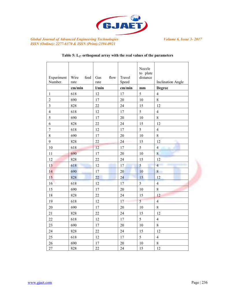
Here the Table 3 below shows the parameters and their levels and the Table-4 shows the L27 Orthogonal array. And the Table 5Shows the L27 orthogonal array with their real values for the experiment to be done.

www.gjaet.com Page | 235
Global Journal of Advanced Engineering Technologies Volume 6, Issue 3- 2017ISSN (Online): 2277-6370 & ISSN (Print):2394-0921
Table 4: Experimental Layout Using an L27 Orthogonal Array
S.No.WFRV
GFR T.S NPDInclinationAngle
1 1 1 1 1 1
2 1 2 1 2 2
3 1 3 1 3 3
4 2 1 1 2 35 2 2 1 3 1
6 2 3 1 1 2
7 3 1 1 3 2
8 3 2 1 1 3
9 3 3 1 2 1
10 1 1 2 1 1
11 1 2 2 2 2
12 1 3 2 3 3
13 2 1 2 2 3
14 2 2 2 3 1
15 2 3 2 1 2
16 3 1 2 3 2
17 3 2 2 1 3
18 3 3 2 2 1
19 1 1 3 1 1
20 1 2 3 2 2
21 1 3 3 3 3
22 2 1 3 2 3
23 2 2 3 3 1
24 2 3 3 1 2
25 3 1 3 3 226 3 2 3 1 3
27 3 3 3 2 1
www.gjaet.com Page | 236
Global Journal of Advanced Engineering Technologies Volume 6, Issue 3- 2017ISSN (Online): 2277-6370 & ISSN (Print):2394-0921
Table 5: L27 orthogonal array with the real values of the parameters
Experiment Number.
Wire feed rate
Gas flow rate
Travel Speed
Nozzle to plate distance
Inclination Angle
cm/min l/min cm/min mm Degree
1 618 12 17 5 4
2 690 17 20 10 8
3 828 22 24 15 12
4 618 12 17 5 4
5 690 17 20 10 8
6 828 22 24 15 12
7 618 12 17 5 4
8 690 17 20 10 8
9 828 22 24 15 12
10 618 12 17 5 4
11 690 17 20 10 8
12 828 22 24 15 12
13 618 12 17 5 4
14 690 17 20 10 8
15 828 22 24 15 12
16 618 12 17 5 4
15 690 17 20 10 8
18 828 22 24 15 12
19 618 12 17 5 4
20 690 17 20 10 8
21 828 22 24 15 12
22 618 12 17 5 4
23 690 17 20 10 8
24 828 22 24 15 12
25 618 12 17 5 4
26 690 17 20 10 827 828 22 24 15 12
www.gjaet.com Page | 237
Global Journal of Advanced Engineering Technologies Volume 6, Issue 3- 2017ISSN (Online): 2277-6370 & ISSN (Print):2394-0921
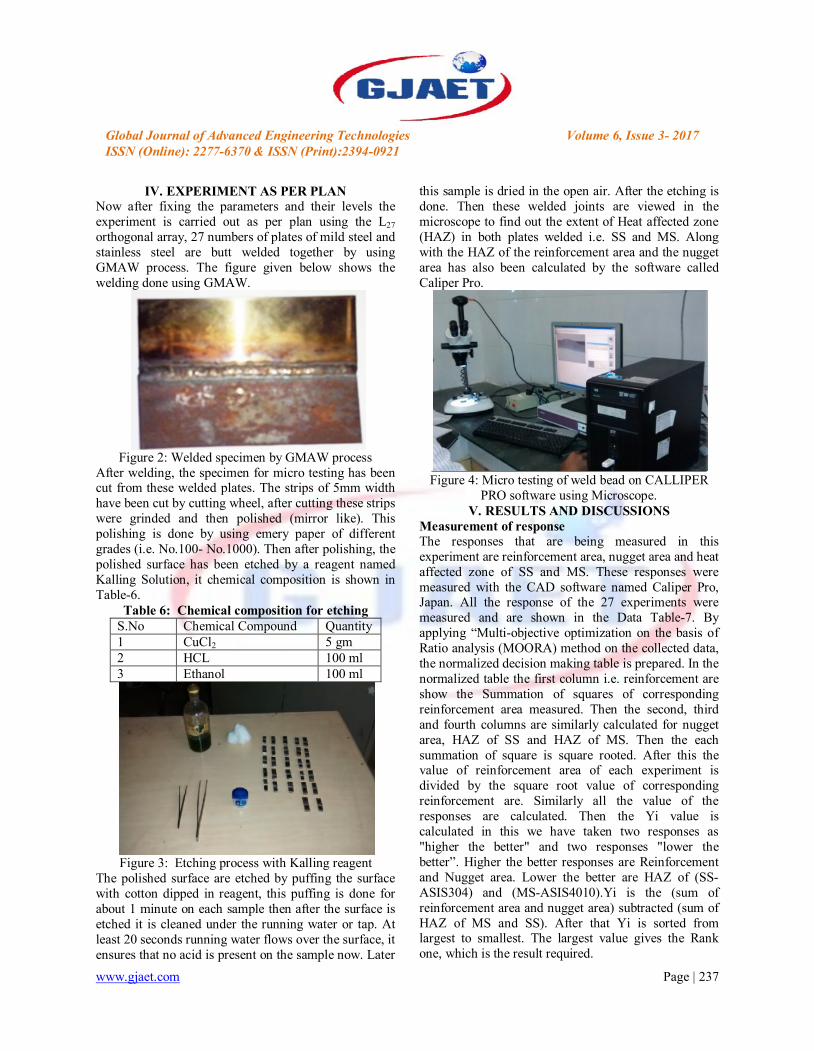
IV. EXPERIMENT AS PER PLANNow after fixing the parameters and their levels the experiment is carried out as per plan using the L27
orthogonal array, 27 numbers of plates of mild steel and stainless steel are butt welded together by using GMAW process. The figure given below shows the welding done using GMAW.
Figure 2: Welded specimen by GMAW processAfter welding, the specimen for micro testing has been cut from these welded plates. The strips of 5mm width have been cut by cutting wheel, after cutting these strips were grinded and then polished (mirror like). This polishing is done by using emery paper of different grades (i.e. No.100- No.1000). Then after polishing, the polished surface has been etched by a reagent named Kalling Solution, it chemical composition is shown in Table-6.
Table 6: Chemical composition for etchingS.No Chemical Compound Quantity1 CuCl2 5 gm2 HCL 100 ml3 Ethanol 100 ml
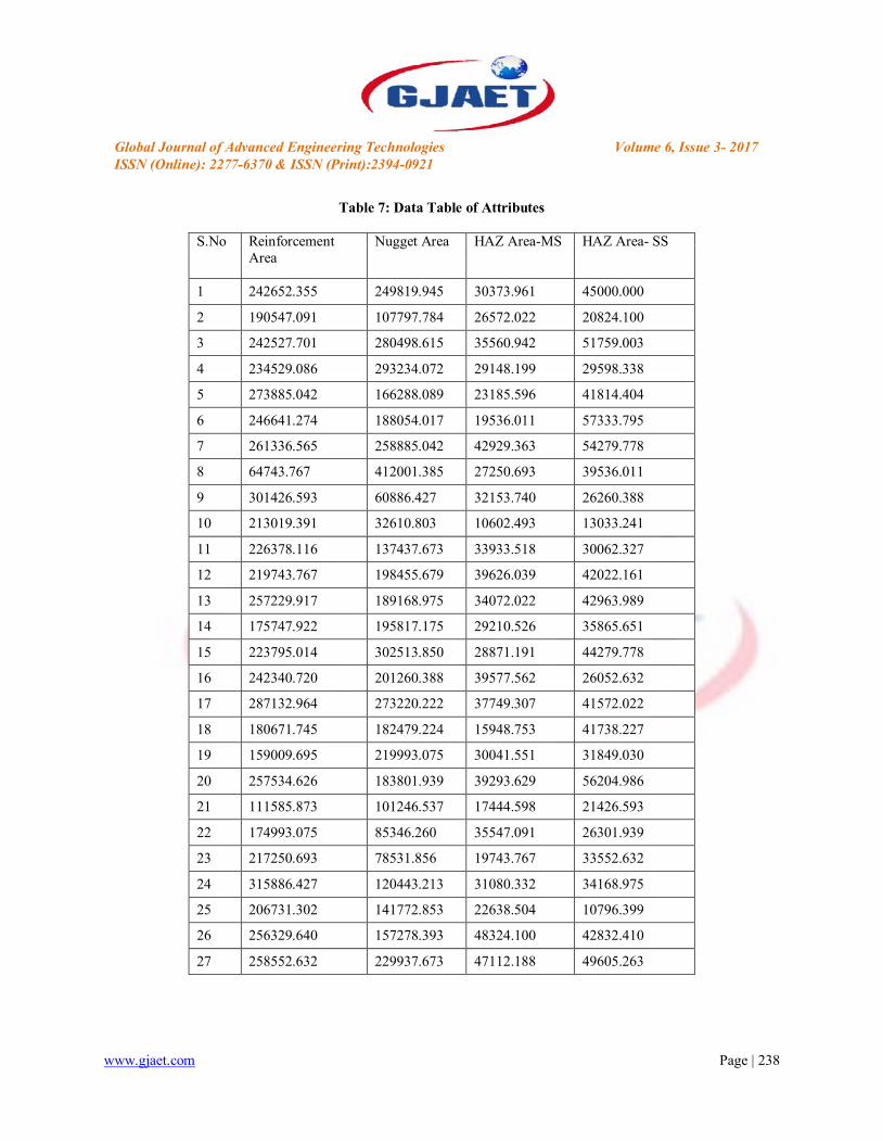
Figure 3: Etching process with Kalling reagentThe polished surface are etched by puffing the surface with cotton dipped in reagent, this puffing is done for about 1 minute on each sample then after the surface is etched it is cleaned under the running water or tap. At least 20 seconds running water flows over the surface, it ensures that no acid is present on the sample now. Later
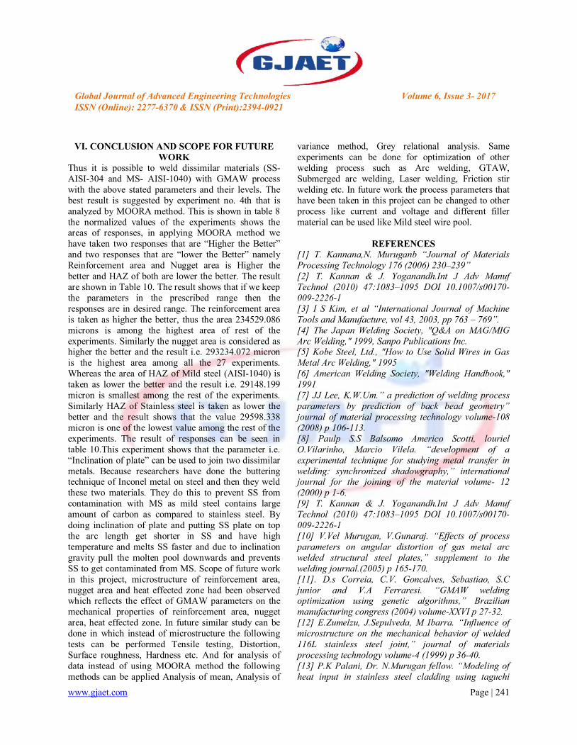
this sample is dried in the open air. After the etching is done. Then these welded joints are viewed in the microscope to find out the extent of Heat affected zone (HAZ) in both plates welded i.e. SS and MS. Along with the HAZ of the reinforcement area and the nugget area has also been calculated by the software called Caliper Pro.
Figure 4: Micro testing of weld bead on CALLIPER PRO software using Microscope.
V. RESULTS AND DISCUSSIONSMeasurement of responseThe responses that are being measured in this experiment are reinforcement area, nugget area and heat affected zone of SS and MS. These responses were measured with the CAD software named Caliper Pro, Japan. All the response of the 27 experiments were measured and are shown in the Data Table-7. By applying “Multi-objective optimization on the basis of Ratio analysis (MOORA) method on the collected data, the normalized decision making table is prepared. In the normalized table the first column i.e. reinforcement are show the Summation of squares of corresponding reinforcement area measured. Then the second, third and fourth columns are similarly calculated for nugget area, HAZ of SS and HAZ of MS. Then the each summation of square is square rooted. After this the value of reinforcement area of each experiment is divided by the square root value of corresponding reinforcement are. Similarly all the value of the responses are calculated. Then the Yi value is calculated in this we have taken two responses as "higher the better" and two responses "lower the better”. Higher the better responses are Reinforcement and Nugget area. Lower the better are HAZ of (SS-ASIS304) and (MS-ASIS4010).Yi is the (sum of reinforcement area and nugget area) subtracted (sum of HAZ of MS and SS). After that Yi is sorted from largest to smallest. The largest value gives the Rank one, which is the result required.
www.gjaet.com Page | 238
Global Journal of Advanced Engineering Technologies Volume 6, Issue 3- 2017ISSN (Online): 2277-6370 & ISSN (Print):2394-0921
Table 7: Data Table of Attributes
S.No Reinforcement Area
Nugget Area HAZ Area-MS HAZ Area- SS
1 242652.355 249819.945 30373.961 45000.000
2 190547.091 107797.784 26572.022 20824.100
3 242527.701 280498.615 35560.942 51759.003
4 234529.086 293234.072 29148.199 29598.338
5 273885.042 166288.089 23185.596 41814.404
6 246641.274 188054.017 19536.011 57333.795
7 261336.565 258885.042 42929.363 54279.778
8 64743.767 412001.385 27250.693 39536.011
9 301426.593 60886.427 32153.740 26260.388
10 213019.391 32610.803 10602.493 13033.241
11 226378.116 137437.673 33933.518 30062.327
12 219743.767 198455.679 39626.039 42022.161
13 257229.917 189168.975 34072.022 42963.989
14 175747.922 195817.175 29210.526 35865.651
15 223795.014 302513.850 28871.191 44279.778
16 242340.720 201260.388 39577.562 26052.632
17 287132.964 273220.222 37749.307 41572.022
18 180671.745 182479.224 15948.753 41738.227
19 159009.695 219993.075 30041.551 31849.030
20 257534.626 183801.939 39293.629 56204.986
21 111585.873 101246.537 17444.598 21426.593
22 174993.075 85346.260 35547.091 26301.939
23 217250.693 78531.856 19743.767 33552.632
24 315886.427 120443.213 31080.332 34168.975
25 206731.302 141772.853 22638.504 10796.399
26 256329.640 157278.393 48324.100 42832.410
27 258552.632 229937.673 47112.188 49605.263

www.gjaet.com Page | 239
Global Journal of Advanced Engineering Technologies Volume 6, Issue 3- 2017ISSN (Online): 2277-6370 & ISSN (Print):2394-0921
Table 8: Normalized Decision-Making Table
Experiment .No
Wire feed rate
Gas flow rate
Travel Speed
Nozzle to plate distance
Inclination Angle
cm/min l/min cm/min mm Degree
1 618 12 17 5 4
2 690 17 20 10 8
3 828 22 24 15 12
4 618 12 17 5 4
5 690 17 20 10 8
6 828 22 24 15 12
7 618 12 17 5 4
8 690 17 20 10 8
9 828 22 24 15 12
10 618 12 17 5 4
11 690 17 20 10 8
12 828 22 24 15 12
13 618 12 17 5 4
14 690 17 20 10 8
15 828 22 24 15 12
16 618 12 17 5 4
15 690 17 20 10 8
18 828 22 24 15 12
19 618 12 17 5 4
20 690 17 20 10 8
21 828 22 24 15 12
22 618 12 17 5 4
23 690 17 20 10 8
24 828 22 24 15 12
25 618 12 17 5 4
26 690 17 20 10 827 828 22 24 15 12
Optimum ResultsBy using MOORA method the optimum process parameters that has come out, is the experiment no 4th, in which the optimum combination of parameter are A2B1C1D2E3. Where the table 9 shows the optimum value of level in their corresponding parameter.

www.gjaet.com Page | 240
Global Journal of Advanced Engineering Technologies Volume 6, Issue 3- 2017ISSN (Online): 2277-6370 & ISSN (Print):2394-0921
Table 9: Optimum Values of Level to the Corresponding Parameter
Table 10: Response Values at Optimized Parameter Range.
S.No. ParameterUnit Value
Reinforcement Area
Nugget AreaHAZ, Mild
Steel
HAZ, Stainless
Steel
1 Wire Feed rate cm/min 690
234529.086 293234.072 29148.199 29598.338
2 Gas Flow rate l/min 12
3 Travel Speed cm/min 17
4Nozzle to Plate Distance mm 10
5Inclination angle of Plate Degree 12
S. No Parameter Unit Value
1 Wire feed rate cm/min 690
2 Gas flow rate l/min 12
3 Travel speed cm/min 17
4 Nozzle to plate distance mm 10
5 Inclination angle of plate Degree 12
www.gjaet.com Page | 241
Global Journal of Advanced Engineering Technologies Volume 6, Issue 3- 2017ISSN (Online): 2277-6370 & ISSN (Print):2394-0921
VI. CONCLUSION AND SCOPE FOR FUTURE WORK
Thus it is possible to weld dissimilar materials (SS-AISI-304 and MS- AISI-1040) with GMAW process with the above stated parameters and their levels. The best result is suggested by experiment no. 4th that is analyzed by MOORA method. This is shown in table 8the normalized values of the experiments shows the areas of responses, in applying MOORA method we have taken two responses that are “Higher the Better” and two responses that are “lower the Better” namely Reinforcement area and Nugget area is Higher the better and HAZ of both are lower the better. The result are shown in Table 10. The result shows that if we keep the parameters in the prescribed range then the responses are in desired range. The reinforcement area is taken as higher the better, thus the area 234529.086 microns is among the highest area of rest of the experiments. Similarly the nugget area is considered as higher the better and the result i.e. 293234.072 micron is the highest area among all the 27 experiments. Whereas the area of HAZ of Mild steel (AISI-1040) is taken as lower the better and the result i.e. 29148.199 micron is smallest among the rest of the experiments. Similarly HAZ of Stainless steel is taken as lower the better and the result shows that the value 29598.338 micron is one of the lowest value among the rest of the experiments. The result of responses can be seen in table 10.This experiment shows that the parameter i.e. “Inclination of plate” can be used to join two dissimilar metals. Because researchers have done the buttering technique of Inconel metal on steel and then they weld these two materials. They do this to prevent SS from contamination with MS as mild steel contains large amount of carbon as compared to stainless steel. By doing inclination of plate and putting SS plate on top the arc length get shorter in SS and have high temperature and melts SS faster and due to inclination gravity pull the molten pool downwards and prevents SS to get contaminated from MS. Scope of future work in this project, microstructure of reinforcement area, nugget area and heat effected zone had been observed which reflects the effect of GMAW parameters on the mechanical properties of reinforcement area, nugget area, heat effected zone. In future similar study can be done in which instead of microstructure the following tests can be performed Tensile testing, Distortion, Surface roughness, Hardness etc. And for analysis of data instead of using MOORA method the following methods can be applied Analysis of mean, Analysis of
variance method, Grey relational analysis. Same experiments can be done for optimization of other welding process such as Arc welding, GTAW, Submerged arc welding, Laser welding, Friction stir welding etc. In future work the process parameters that have been taken in this project can be changed to other process like current and voltage and different filler material can be used like Mild steel wire pool.
REFERENCES[1] T. Kannana,N. Muruganb “Journal of Materials Processing Technology 176 (2006) 230–239”[2] T. Kannan & J. Yoganandh.Int J Adv Manuf Technol (2010) 47:1083–1095 DOI 10.1007/s00170-009-2226-1[3] I S Kim, et al “International Journal of Machine Tools and Manufacture, vol 43, 2003, pp 763 – 769”.[4] The Japan Welding Society, "Q&A on MAG/MIG Arc Welding," 1999, Sanpo Publications Inc.[5] Kobe Steel, Ltd., "How to Use Solid Wires in Gas Metal Arc Welding," 1995[6] American Welding Society, "Welding Handbook," 1991[7] JJ Lee, K.W.Um.” a prediction of welding process parameters by prediction of back bead geometry” journal of material processing technology volume-108 (2008) p 106-113.[8] Paulp S.S Balsomo Americo Scotti, louriel O.Vilarinho, Marcio Vilela. “development of a experimental technique for studying metal transfer in welding: synchronized shadowgraphy,” international journal for the joining of the material volume- 12 (2000) p 1-6.[9] T. Kannan & J. Yoganandh.Int J Adv Manuf Technol (2010) 47:1083–1095 DOI 10.1007/s00170-009-2226-1[10] V.Vel Murugan, V.Gunaraj. “Effects of process parameters on angular distortion of gas metal arc welded structural steel plates,” supplement to the welding journal.(2005) p 165-170.[11]. D.s Correia, C.V. Goncalves, Sebastiao, S.C junior and V.A Ferraresi. “GMAW welding optimization using genetic algorithms,” Brazilian manufacturing congress (2004) volume-XXVI p 27-32.[12] E.Zumelzu, J.Sepulveda, M Ibarra. “Influence of microstructure on the mechanical behavior of welded 116L stainless steel joint,” journal of materials processing technology volume-4 (1999) p 36-40.[13] P.K Palani, Dr. N.Murugan fellow. “Modeling of heat input in stainless steel cladding using taguchi
www.gjaet.com Page | 242
Global Journal of Advanced Engineering Technologies Volume 6, Issue 3- 2017ISSN (Online): 2277-6370 & ISSN (Print):2394-0921
design of experiments,” i.e(i) journal-MC (2007) volume-87 p28-34.[14] P.E Murray. “Selecting parameter for GMAW using dimensional analysis,” welding journal (2008) p 125-130.[15] Benyounis KY, Olabi AG (2008) Optimization of different welding processes using statistical and numerical approaches-a reference guide. Adv Eng softw 39:483-496.[16] Rao RV (2007) Decision making in the manufacturing environment: using graph theory and fuzzy multiple attribute decision making methods. Springer, London.[17] SUPPLEMENT TO THE WELDING JOURNAL, AUGUST 2005 Sponsored by the American Welding Society and the Welding Research Council.