g t rail alu 01-2011 - r2muhendislik.com · • ponts roulants • chemins de roulement •...
TRANSCRIPT

RAIL ALUMINIUM
VERLINDE se reserve le droi t de modi f ier sans preavis les caracter is t iques de son mater ie l VERLINDE reserve the r ight to al ter or amend the above informat ion without not ice VERLINDE behäl t sich das Recht um Veränderungen vor
01/2011GTRAILALUENGFRAGER
GUIDE TECHNIQUE TECHNICAL GUIDE
TECHNISCHES HANDBUCH
SYSTEME DE MANUTENTION LEGERE ALUMINIUM ALUMINIUM LIGHT CRANE SYSTEM
ALUMINIUM LEICHBAUKRANSYSTEM

Technical guide EUROSYSTEM ALUGuide technique EUROSYSTEM ALU
Technisches Handbuch EUROSYSTEM ALU
EurosystemALU 1 GTENG/FRA/GER01/2011
TECHNICAL
GUIDE EUROSYSTEM
ALU
GUIDE TECHNIQUE
EUROSYSTEM ALU
TECHNISCHES HANDBUCH
EUROSYSTEM ALU
TABLE OF CONTENTS TABLE DES MATIERES INHALTSVERZEICHNIS
HOW TO READ THIS MANUAL COMMENT LIRE CE MANUEL ZUR BENUTZUNG DES HANDBUCHS GENERALS GENERALITES ALLGEMEINE COMPLETE SYSTEMS SYSTEMES COMPLETS KOMPLETTE ANLAGEN Description Description Beschreibung ALSA single girder articulated bridge Poutre monopoutre articulée ALSA Einträgergelenklaufkran ALSA ALSL single girder low headroom bridge Poutre monopoutre encastrée ALSL Einträgerlaufkran kurze Bauhöhe ALSL ALDA double girder articulated bridge Poutre bipoutre articulée ALDA Zweiträgergelenklaufkran ALDA ALDL double girder low headroom bridge Poutre bipoutre encastré ALDL Zweiträgerlaufkran kurze Bauhöhe ALDL ALM straight monorail Monorail droit ALM Einschienenbahn ALM Power feeding lines Lignes d’alimentation Stromzuführungen Electric chain hoists EUROCHAIN VL Palans à chaine EUROCHAIN VL Elektrokettenzüge EUROCHAIN VL EUROSYSTEM ALU COMPONENTS COMPOSANTS EUROSYSTEM ALU KOMPONENTEN EUROSYSTEM ALU Profiles Profilés Profile Connections & End plates Kits de liaison & Kits de fermeture Profilverbindungen & Endplatten Suspensions Suspensions Aufhängungen Manual trolleys Chariots manuels Schiebefahrwerke Bridge trolleys Chariots de poutre Kranfahrwerke Motor trolleys ALTM Chariots motorisés ALTM Motor-Fahrwerke ALTM
HOW TO READ THIS MANUAL COMMENT LIRE CE MANUEL ZUR BENUTZUNG DES HANDBUCHS
In the first part of this Guide VERLINDE presents the complete EUROSYSTEM ALU light crane systems, that is to say : • Bridges • Runways • Monorails and circuits and their ideal surrounding components • Chain and belt hoists • Power feeding lines Select these turn-key solutions with your own criteria : • Safe Working Load • Building dimensions • Duty factor • Working process The second part of this Guide is more technical and gives detailed information on the following sub-assemblies for complete systems : • Selection of the suspensions • Dimensions of the sub-assemblies • Code of the sub-assemblies
VERLINDE vous présente dans la première partie de ce Guide les systèmes de manutention EUROSYSTEM ALU : • Ponts roulants • Chemins de roulement • Monorails et circuits et leurs indispensables compléments : • Palans à chaine et à sangle • Lignes d’ alimentation Sélectionnez ces solutions clé-en-main à partir de vos critères : • Capacité de charge • Encombrements disponibles • Cadences d’ utilisation • Process La deuxième partie de ce Guide, plus technique, est consacrée aux composants des systèmes précédents. Vous y trouverez des informations plus détaillées sur : • La sélection des suspensions • Les encombrements des sous-
ensembles • Les codes des sous-ensembles
Im ersten Teil dieses Handbuchs stellt Ihnen VERLINDE die kompletten EUROSYSTEM ALU vor: • Krane • Fahrbahnen • Einschienenbahnen und die notwendigen Komponenten : • Elektroketten- und Bandzüge • Stromzuführungen Wählen Sie Ihre Systemlösungen nach folgenden Kriterien aus: • Traglast • Baumaße • Beanspruchungsgruppen • Anwendung Der zweite (technische) Teil dieses Handbuchs befasst sich mit den nötigen Komponenten zur Komplettierung der Leichtbaukrane. Sie finden detaillierte Informationen zu: • Auswahl der Aufhängungen • Maße der Komponenten • Kodierungen der Komponenten
Technical guide EUROSYSTEM ALUGuide technique EUROSYSTEM ALU
Technisches Handbuch EUROSYSTEM ALU
EurosystemALU 2 GTENG/FRA/GER01/2011
GENERALS GENERALITES ALLGEMEINE
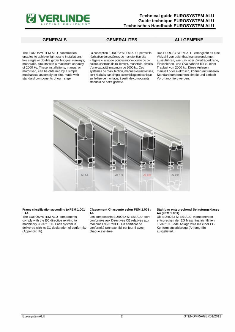
The EUROSYSTEM ALU construction enables to achieve light crane installations like single or double girder bridges, runways, monorails, circuits with a maximum capacity of 2000 kg. These installations, manual or motorised, can be obtained by a simple mechanical assembly on site, made with standard components of our range.
La conception EUROSYSTEM ALU permet la réalisation de systèmes de manutention dite « légère », à savoir poutres mono-poutre ou bi-poutre, chemins de roulement, monorails, circuits, d’une capacité maximum de 2000 kg. Ces systèmes de manutention, manuels ou motorisés, sont réalisés par simple assemblage mécanique sur le lieu de montage, à partir de composants standard de notre gamme.
Das EUROSYSTEM ALU ermöglicht es eine Vielzahl von Leichtbaukrananwendungen auszuführen, wie Ein- oder Zweiträgerkrane, Einschienen- und Ovalbahnen bis zu einer Traglast von 2000 kg. Diese Anlagen, manuell oder elektrisch, können mit unseren Standardkomponenten simple und einfach Vorort montiert werden.
Frame classification according to FEM 1.001 : A4. The EUROSYSTEM ALU components comply with the EC directive relating to machinery 98/37/EEC. Each system is delivered with its EC declaration of conformity (Appendix IIb).
Classement Charpente selon FEM 1.001 : A4 Les composants EUROSYSTEM ALU sont conformes aux Directives CE relatives aux machines 98/37/CEE. Un certificat de conformité (annexe IIb) est fourni avec chaque système.
Stahlbau entsprechend Belastungsklasse A4 (FEM 1.001). Die EUROSYSTEM ALU Komponenten entsprechen der EG Maschinenrichtlinien 98/37/EG. Jede Anlage wird mit einer EG Konformitätserklärung (Anhang IIb) ausgeliefert.

Technical guide EUROSYSTEM ALUGuide technique EUROSYSTEM ALU
Technisches Handbuch EUROSYSTEM ALU
EurosystemALU 3 GTENG/FRA/GER01/2011
Lifting devices The EUROSYSTEM ALU light crane system is typically designed to suit our range of EUROCHAIN chain hoists. Anyway, for some particular environments (clean areas, corrosive atmosphere, heavy duties …), the EUROLIFT BH belt hoists will be preferred since they are quite compatible with the EUROSYSTEM ALU components.
Appareils de levage Le système de manutention EUROSYSTEM ALU est idéalement conçu pour recevoir nos palans à chaine de la gamme EUROCHAIN. Cependant, pour certains environnements particuliers (ambiance propre, atmosphère corrosive, cadences élevées …), on préférera les palans à sangle EUROLIFT BH, parfaitement compatibles avec les composants EUROSYSTEM ALU.
Hebezeuge Das EUROSYSTEM ALU Leichtbaukransystem ist speziell an unsere Kettenzugbaureihe EUROCHAIN angepasst. Für bestimmte Einsatzzwecke (Reinraum, aggressive Umgebung, schwerer Einsatz …) sind auch Bandzüge von der Reihe EUROLIFT BH auswählbar.
Scope of supply The delivery of a complete EUROSYSTEM ALU installation includes the following components ready for assembly : • The profiles cut at length, the end plates
and the connection sets • The bridge trolleys in the construction
selected (articulated, rigid or low headroom)
• The hoist trolley • The power feeding lines (if selected) • The suspensions (to be specified
separately as depending on the building structure)
The lifting unit (chain hoist or belt hoist) must be specified separately.
Limites de fourniture La fourniture d’un ensemble EUROSYSTEM ALU inclut les composants suivants, livrés prêts au montage :
• Les profilés coupés à longueur, les kits d’extrémité et de jonction
• Les chariots de pont dans la version choisie (articulée, rigide ou encastrée)
• Le chariot porte palan • Les lignes d’alimentation (si
sélectionnées) • Les suspensions (à spécifier
séparément car dépendant de la structure porteuse)
L’unité de levage (palan à chaine ou à sangle) est à spécifier séparément.
Lieferumfang Der Lieferumfang einer kompletten EUROSYSTEM ALU Anlage schließt folgende Komponenten ein : • Die Profile, maßgeschneidert, die
Endplatten und die Verbindungssätze • Die Kranfahrwerke für die ausgewählte
Konstruktion (Gelenkig, starr oder kurze Bauhöhe)
• Das Zug-Fahrwerk • Die Stromzuführung (falls gewünscht) • Die Aufhängungen (müssen detailliert
angegeben werden, da von der Installation abhängig)
Das Hebezeug muß gesondert aufgeführt werden.
Technical guide EUROSYSTEM ALUGuide technique EUROSYSTEM ALU
Technisches Handbuch EUROSYSTEM ALU
EurosystemALU 4 GTENG/FRA/GER01/2011
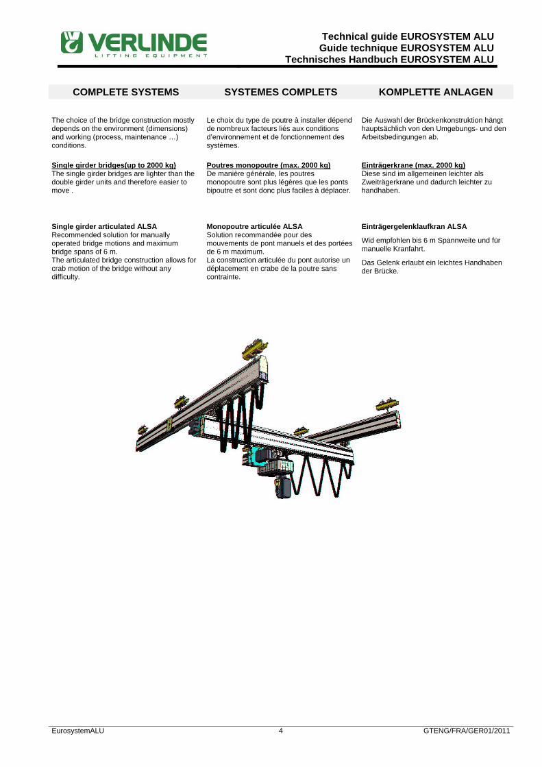
COMPLETE SYSTEMS SYSTEMES COMPLETS KOMPLETTE ANLAGEN The choice of the bridge construction mostly depends on the environment (dimensions) and working (process, maintenance …) conditions.
Le choix du type de poutre à installer dépend de nombreux facteurs liés aux conditions d’environnement et de fonctionnement des systèmes.
Die Auswahl der Brückenkonstruktion hängt hauptsächlich von den Umgebungs- und den Arbeitsbedingungen ab.
Single girder bridges(up to 2000 kg) The single girder bridges are lighter than the double girder units and therefore easier to move .
Poutres monopoutre (max. 2000 kg) De manière générale, les poutres monopoutre sont plus légères que les ponts bipoutre et sont donc plus faciles à déplacer.
Einträgerkrane (max. 2000 kg) Diese sind im allgemeinen leichter als Zweiträgerkrane und dadurch leichter zu handhaben.
Single girder articulated ALSA Recommended solution for manually operated bridge motions and maximum bridge spans of 6 m. The articulated bridge construction allows for crab motion of the bridge without any difficulty.
Monopoutre articulée ALSA Solution recommandée pour des mouvements de pont manuels et des portées de 6 m maximum. La construction articulée du pont autorise un déplacement en crabe de la poutre sans contrainte.
Einträgergelenklaufkran ALSA
Wid empfohlen bis 6 m Spannweite und für manuelle Kranfahrt.
Das Gelenk erlaubt ein leichtes Handhaben der Brücke.

Technical guide EUROSYSTEM ALUGuide technique EUROSYSTEM ALU
Technisches Handbuch EUROSYSTEM ALU
EurosystemALU 5 GTENG/FRA/GER01/2011
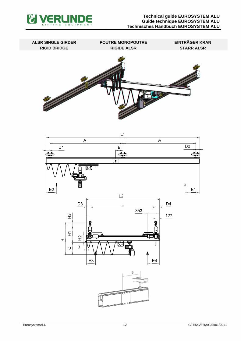
Single girder rigid ALSR Recommended solution for motorized bridge motions and/or bridge spans higher than 6 m. The triangular (rigid) bridge construction prevents any crab motion.
Monopoutre rigide ALSR
Solution recommandée pour des mouvements de pont motorisés et/ou des portées supérieures à 6 m. La construction rigide du pont empêche la mise en crabe du pont.
Einträgerlaufkran starr ALSR
Wird empfohlen für elektrische Kranfahrt und Spannweiten über 6 m. Die Brücke verfährt immer rechtwinklig zur Kranbahn.
Single girder low headroom ALSL The low headroom construction allows for longer spans than the articulated version and also significantly improves the headroom of the system and therefore the vertical hook stroke of the hoist. Bridge cantilevers are not possible. The low headroom construction allows for longer spans than the articulated or rigid ones.
Monopoutre encastrée ALSL La construction encastrée autorise des portées plus importantes que les versions articulées. Elle diminue également la hauteur perdue du système, et augmente donc la course verticale du crochet de levage. Pas de déport de poutre possible. La construction encastrée autorise des portées plus importantes que les versions articulées ou rigides
Einträgerlaufkran kurze Bauhöhe ALSL Die kurze Konstruktion ermöglicht längeren Spannweiten als die Standard-Gelenkausführung und ebenfalls verbessert die gesamte Bauhöhe und demnach den Hakenweg. Eine Auskragung ist nicht möglich.
Die kurze Konstruktion ermöglicht längeren Spannweiten als die Standard order starre Ausführung.

Technical guide EUROSYSTEM ALUGuide technique EUROSYSTEM ALU
Technisches Handbuch EUROSYSTEM ALU
EurosystemALU 6 GTENG/FRA/GER01/2011
Double girder bridges up to to 2000 kg The double girder bridges allow for longer span than the single girder ones and also offer a shorter headroom.
Poutres bi-poutre (max. 2000 kg) Les poutres bi-poutre autorisent une portée plus importante que les ponts mono-poutre ainsi qu’une hauteur perdue plus réduite.
Zweiträgerkrane (max. 2000 kg) Zweiträgerkrane ermöglichen grössere Spannweiten, grössere Traglasten und kleinere Baumaße.
Double girder articulated ALDA Recommended solution for manually operated bridge motions.
Bipoutre articulée ALDA Solution recommandée en cas de déplacements de pont manuels.
Zweiträgergelenklaufkran ALDA Wird empfohlen für die manuelle Kranfahrt.
Double girder rigid ALDR Recommended solution for motorized bridge motions. The triangular (rigid) bridge construction prevents any crab motion.
Bipoutre rigide ALDR
Application recommandée pour mouvement de ponts motorisés. La construction rigide du pont empêche la mise en crabe du pont.
Zweiträgerlaufkran starr ALDR
Wird empfohlen für elektrische Kranfahrt. Der Kran verfährt immer rechtwinklig zur Kranbahn.
Technical guide EUROSYSTEM ALUGuide technique EUROSYSTEM ALU
Technisches Handbuch EUROSYSTEM ALU
EurosystemALU 7 GTENG/FRA/GER01/2011
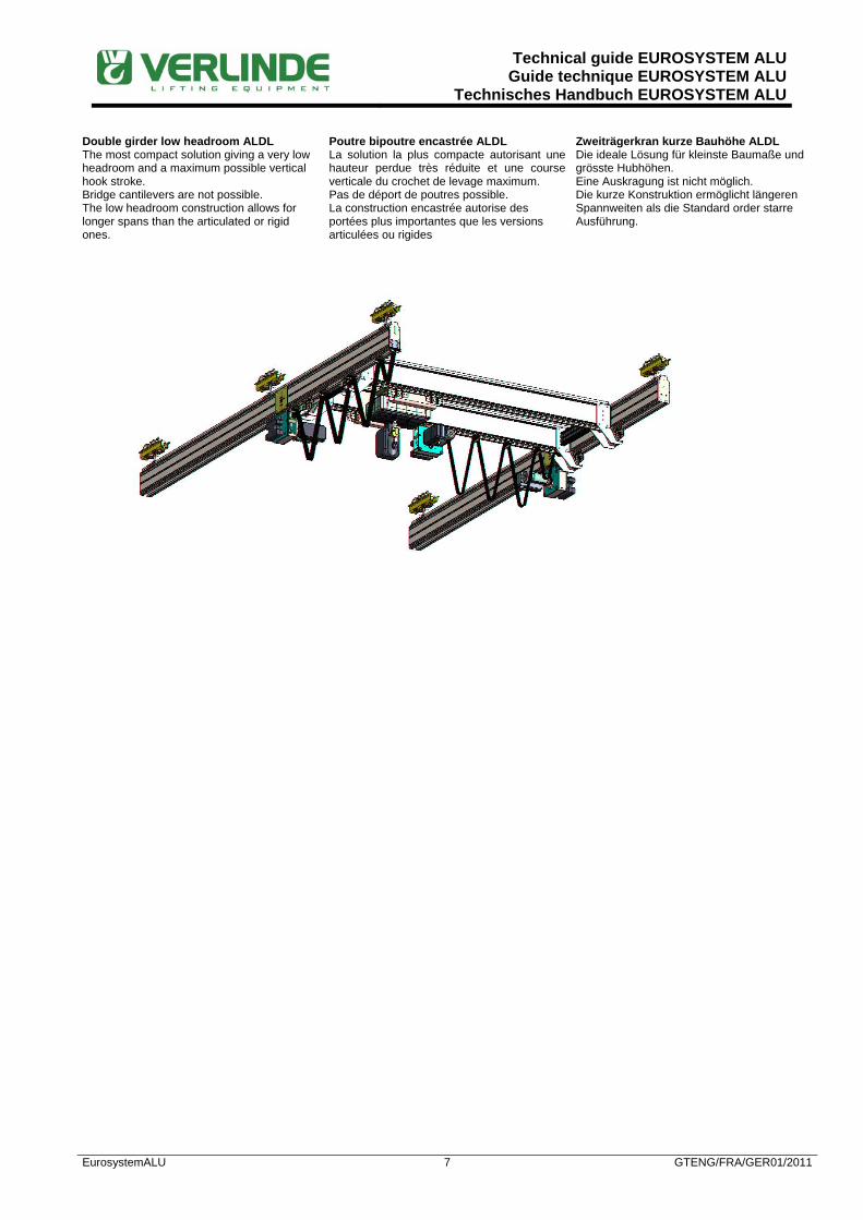
Double girder low headroom ALDL The most compact solution giving a very low headroom and a maximum possible vertical hook stroke. Bridge cantilevers are not possible. The low headroom construction allows for longer spans than the articulated or rigid ones.
Poutre bipoutre encastrée ALDL La solution la plus compacte autorisant une hauteur perdue très réduite et une course verticale du crochet de levage maximum. Pas de déport de poutres possible. La construction encastrée autorise des portées plus importantes que les versions articulées ou rigides
Zweiträgerkran kurze Bauhöhe ALDL Die ideale Lösung für kleinste Baumaße und grösste Hubhöhen. Eine Auskragung ist nicht möglich. Die kurze Konstruktion ermöglicht längeren Spannweiten als die Standard order starre Ausführung.

Technical guide EUROSYSTEM ALUGuide technique EUROSYSTEM ALU
Technisches Handbuch EUROSYSTEM ALU
EurosystemALU 8 GTENG/FRA/GER01/2011
ALSA SINGLE GIRDER ARTICULATED BRIDGE
POUTRE MONOPOUTRE ARTICULEE ALSA
EINTRÄGER GELENKKRAN ALSA

Technical guide EUROSYSTEM ALUGuide technique EUROSYSTEM ALU
Technisches Handbuch EUROSYSTEM ALU
EurosystemALU 9 GTENG/FRA/GER01/2011
ALSA SINGLE GIRDER ARTICULATED BRIDGE
POUTRE MONOPOUTRE ARTICULEE ALSA
EINTRÄGER GELENKKRAN ALSA
SWL Cap.
Traglast (kg)
Bridge Poutre
Kranbrücke
Runway Ch de rlt
Kranbahn
Dimensions (calculated with a maximum deflection 1/500) Dimensions (calculées avec une flèche maxi de 1/500)
Maße (berechnet mit max. Durchbiegung 1/500)
L maxi (mm)
Profile Profilé Profil
A maxi (mm)
Profile Profilé Profil
B maxi(mm)
D3/D4 mini (mm)
D3/D4 maxi (mm)
D1/D2 mini (mm)
D1/D2 maxi (mm)
C (mm)
H(1) (mm)
H1 (mm)
H2 (mm)
H3(1) (mm)
E3(2) (mm)
E1(2) (mm)
63 6250 AL06 6250 AL06 625 100
Plea
se c
onsu
lt us
/ N
ous
cons
ulte
r / A
uf A
nfra
ge
100
Plea
se c
onsu
lt us
/ N
ous
cons
ulte
r / A
uf A
nfra
ge
310 870 410 175 150 140 140
8700 AL08 870 100 100 310 920 460 175 150 140 140
8700 AL10 870 100 100 310 965 505 175 150 140 150
8700 AL14 870 100 100 310 995 535 175 150 140 150
8700 AL08 8700 AL08 870 100 100 310 970 510 225 150 140 140
8700 AL10 870 100 100 310 1015 555 225 150 140 150
8700 AL14 870 100 100 310 1045 585 225 150 140 150
8700 AL10 8700 AL10 870 100 100 310 1050 590 270 150 150 150
8700 AL14 870 100 100 310 1080 620 270 150 150 150
8700 AL14 8700 AL10 870 100 100 310 1080 620 300 150 150 150
8700 AL14 870 100 100 310 1115 655 300 150 150 150
80 5750 AL06 5750 AL06 575 100 100 310 870 410 175 150 140 140
8300 AL08 830 100 100 310 920 460 175 150 140 140
8700 AL10 870 100 100 310 965 505 175 150 140 150
8700 AL14 870 100 100 310 995 535 175 150 140 150
8300 AL08 8300 AL08 830 100 100 310 970 510 225 150 140 140
8700 AL10 870 100 100 310 1015 555 225 150 140 150
8700 AL14 870 100 100 310 1045 585 225 150 140 150
8700 AL10 8700 AL10 870 100 100 310 1050 590 270 150 150 150
8700 AL14 870 100 100 310 1080 620 270 150 150 150
8700 AL14 8700 AL10 870 100 100 310 1080 620 300 150 150 150
8700 AL14 870 100 100 310 1115 655 300 150 150 110
125 4850 AL06 4850 AL06 485 100 100 310 870 410 175 150 140 140
7200 AL08 720 100 100 310 920 460 175 150 140 140
8500 AL10 850 100 100 310 965 505 175 150 140 150
8700 AL14 870 100 100 310 995 535 175 150 140 150
7200 AL08 7200 AL08 720 100 100 310 970 510 225 150 140 140
8500 AL10 850 100 100 310 1015 555 225 150 140 150
8700 AL14 870 100 100 310 1045 585 225 150 140 150
8500 AL10 8500 AL10 850 100 100 310 1050 590 270 150 150 150
8700 AL14 870 100 100 310 1080 620 270 150 150 150
8700 AL14 8500 AL10 850 100 100 310 1080 620 300 150 150 150
8700 AL14 870 100 100 310 1115 655 300 150 150 150
160 4440 AL06 4440 AL06 444 100 100 334 894 410 175 150 140 140
6600 AL08 660 100 100 334 944 460 175 150 140 140
7850 AL10 785 100 100 334 989 505 175 150 140 150
8700 AL14 870 100 100 334 1019 535 175 150 140 150
6600 AL08 6600 AL08 660 100 100 334 994 510 225 150 140 140
7850 AL10 785 100 100 334 1039 555 225 150 140 150
8700 AL14 870 100 100 334 1069 585 225 150 140 150
7850 AL10 7850 AL10 785 100 100 334 1074 590 270 150 150 150
8700 AL14 870 100 100 334 1104 620 270 150 150 150
8700 AL14 7850 AL10 785 100 100 334 1104 620 300 150 150 150
8700 AL14 870 100 100 334 1139 655 300 150 150 150

Technical guide EUROSYSTEM ALUGuide technique EUROSYSTEM ALU
Technisches Handbuch EUROSYSTEM ALU
EurosystemALU 10 GTENG/FRA/GER01/2011
ALSA SINGLE GIRDER ARTICULATED BRIDGE
POUTRE MONOPOUTRE ARTICULEE ALSA
EINTRÄGER GELENKKRAN ALSA
SWL Cap.
Traglast (kg)
Bridge Poutre
Kranbrücke
Runway Ch de rlt
Kranbahn
Dimensions (calculated with a maximum deflection 1/500) Dimensions (calculées avec une flèche maxi de 1/500)
Maße (berechnet mit max. Durchbiegung 1/500)
L maxi (mm)
Profile Profilé Profil
A maxi (mm)
Profile Profilé Profil
B maxi(mm)
D3/D4 mini (mm)
D3/D4 maxi (mm)
D1/D2 mini (mm)
D1/D2 maxi (mm)
C (mm)
H(1) (mm)
H1 (mm)
H2 (mm)
H3(1) (mm)
E3(2) (mm)
E1(2) (mm)
250 3600 AL06 3600 AL06 360 100
Plea
se c
onsu
lt us
/ N
ous
cons
ulte
r / A
uf A
nfra
ge
100
Plea
se c
onsu
lt us
/ N
ous
cons
ulte
r / A
uf A
nfra
ge
334 894 410 175 150 140 140
5500 AL08 550 100 100 334 944 460 175 150 140 140
6650 AL10 665 100 100 334 989 505 175 150 140 150
8450 AL14 845 100 100 334 1019 535 175 150 140 150
5500 AL08 5500 AL08 550 100 100 334 994 510 225 150 140 140
6650 AL10 665 100 100 334 1039 555 225 150 140 150
8450 AL14 845 100 100 334 1069 585 225 150 140 150
6650 AL10 6650 AL10 665 100 100 334 1074 590 270 150 150 150
8450 AL14 845 100 100 334 1104 620 270 150 150 150
8450 AL14 6650 AL10 665 100 100 334 1104 620 300 150 150 150
8450 AL14 845 100 100 334 1139 655 300 150 150 150
320 3200 AL06 3200 AL06 320 100 100 403 963 410 175 150 140 140
4950 AL08 495 100 100 403 1013 460 175 150 140 140
6000 AL10 600 100 100 403 1058 505 175 150 140 150
7700 AL14 770 100 100 403 1088 535 175 150 140 150
4950 AL08 4950 AL08 495 100 100 403 1063 510 225 150 140 140
6000 AL10 600 100 100 403 1108 555 225 150 140 150
7700 AL14 770 100 100 403 1138 585 225 150 140 150
6000 AL10 6000 AL10 600 100 100 403 1143 590 270 150 150 150
7700 AL14 770 100 100 403 1173 620 270 150 150 150
7700 AL14 6000 AL10 600 100 100 403 1173 620 300 150 150 150
7700 AL14 770 100 100 403 1208 655 300 150 150 150
400 4500 AL08 4500 AL08 450 100 100 403 1063 510 225 150 140 140
5500 AL10 550 100 100 403 1108 555 225 150 140 150
7100 AL14 710 100 100 403 1138 585 225 150 140 150
5500 AL10 5500 AL10 550 100 100 403 1143 590 270 150 150 150
7100 AL14 710 100 100 403 1173 620 270 150 150 150
7100 AL14 5500 AL10 550 100 100 403 1173 620 300 150 150 150
7100 AL14 710 100 100 403 1208 655 300 150 150 150
500 4050 AL08 4050 AL08 405 100 100 403 1063 510 225 150 140 140
4950 AL10 495 100 100 403 1108 555 225 150 140 150
6450 AL14 645 100 100 403 1138 585 225 150 140 150
4950 AL10 4950 AL10 495 100 100 403 1143 590 270 150 150 150
6450 AL14 645 100 100 403 1173 620 270 150 150 150
6450 AL14 4950 AL10 495 100 100 403 1173 620 300 150 150 150
6450 AL14 645 100 100 403 1208 655 300 150 150 150
630 4450 AL10 4450 AL10 445 100 100 455 1195 590 270 150 150 150
5850 AL14 585 100 100 455 1225 620 270 150 150 150
5850 AL14 4450 AL10 445 100 100 455 1225 620 300 150 150 150
5850 AL14 585 100 100 455 1260 655 300 150 150 150

Technical guide EUROSYSTEM ALUGuide technique EUROSYSTEM ALU
Technisches Handbuch EUROSYSTEM ALU
EurosystemALU 11 GTENG/FRA/GER01/2011
ALSA SINGLE GIRDER ARTICULATED BRIDGE
POUTRE MONOPOUTRE ARTICULEE ALSA
EINTRÄGER GELENKKRAN ALSA
SWL Cap.
Traglast (kg)
Bridge Poutre
Kranbrücke
Runway Ch de rlt
Kranbahn
Dimensions (calculated with a maximum deflection 1/500) Dimensions (calculées avec une flèche maxi de 1/500)
Maße (berechnet mit max. Durchbiegung 1/500)
L maxi (mm)
Profile Profilé Profil
A maxi (mm)
Profile Profilé Profil
B maxi(mm)
D3/D4 mini (mm)
D3/D4 maxi (mm)
D1/D2 mini (mm)
D1/D2 maxi (mm)
C (mm)
H(1) (mm)
H1 (mm)
H2 (mm)
H3(1) (mm)
E3(2) (mm)
E1(2) (mm)
800 3950 AL10 3950 AL10 395 100 100 455 1195 590 270 150 150 150
5250 AL14 525 100 100 455 1225 620 270 150 150 150
5250 AL14 3950 AL10 395 100 100 455 1225 620 300 150 150 150
5250 AL14 525 100 100 455 1260 655 300 150 150 150
1000 3550 AL10 3550 AL10 355 100 100 455 1195 590 270 150 150 150
4700 AL14 470 100 100 455 1225 620 270 150 150 150
4700 AL14 3550 AL10 355 100 100 455 1225 620 300 150 150 150
4700 AL14 470 100 100 455 1260 655 300 150 150 150
1250 3200 AL10 3200 AL10 320 100 100 570 1310 590 270 150 150 150
4250 AL14 425 100 100 570 1340 620 270 150 150 150
4250 AL14 3200 AL10 320 100 100 570 1340 620 300 150 150 150
4250 AL14 425 100 100 570 1375 655 300 150 150 150
(1)Minimum values with a short type suspension and C hoist dimension as per table page 32. (2)Values with manual trolley. Please add 400 mm in case of a ALTM motor trolley.
(1)Valeurs mini avec une suspension courte et côte C palan selon tableau page 32. (2)Valeurs avec chariot manuel. Ajouter 400 mm dans le cas d’un chariot motorisé ALTM.
(1)Minimal mögliche Höhe mit einer kurzen Aufhängung und C-Mass gemäs Tabelle Seite 32. (2)Maße für Rollfahrwerke. Bei einem Motorfahrwerk ALTM müssen 400 mm hinzu gerechnet werden
E2 = E1+ (L1* 0,07) in case of flat cable power supply. E2 = E1 in case of enclosed conductors parallel E4 = E3 + (L2* 0,07) in case of flat cable power supply. E4 = E3 in case of enclosed conductors parallel
E2 = E1 + (L1* 0,07) avec une alimentation par câble souple plat. E2 = E1 avec une alimentation en gaine protégée parallèle. E4 = E3 + (L2* 0,07) avec une alimentation par câble souple plat. E4 = E3 avec une alimentation en gaine protégée parallèle.
E2 = E1 + (L1* 0,07) mit Flachkabel unter dem Profil. E2 = E1 mit Schleifleitung parallel E4 = E3 + (L2* 0,07) mit Flachkabel unter dem Profil. E4 = E3 mit Schleifleitung parallel.
Technical guide EUROSYSTEM ALUGuide technique EUROSYSTEM ALU
Technisches Handbuch EUROSYSTEM ALU
EurosystemALU 12 GTENG/FRA/GER01/2011
ALSR SINGLE GIRDER
RIGID BRIDGE POUTRE MONOPOUTRE
RIGIDE ALSREINTRÄGER KRAN
STARR ALSR

Technical guide EUROSYSTEM ALUGuide technique EUROSYSTEM ALU
Technisches Handbuch EUROSYSTEM ALU
EurosystemALU 13 GTENG/FRA/GER01/2011
ALSR SINGLE GIRDER
RIGID BRIDGE POUTRE MONOPOUTRE
RIGIDE ALSREINTRÄGER KRAN
STARR ALSR
SWL Cap.
Traglast (kg)
Bridge Poutre
Kranbrücke
Runway Ch de rlt
Kranbahn
Dimensions (calculated with a maximum deflection 1/500) Dimensions (calculées avec une flèche maxi de 1/500)
Maße (berechnet mit max. Durchbiegung 1/500)
L maxi (mm)
Profile Profilé Profil
A maxi (mm)
Profile Profilé Profil
B maxi(mm)
D3/D4 mini (mm)
D3/D4 maxi (mm)
D1/D2 mini (mm)
D1/D2 maxi (mm)
C (mm)
H(1) (mm)
H1 (mm)
H2 (mm)
H3(1) (mm)
E3(2) (mm)
E1(2) (mm)
63 8700 AL10 8700 AL10 870 125
Plea
se c
onsu
lt us
/ N
ous
cons
ulte
r / A
uf A
nfra
ge
100
Plea
se c
onsu
lt us
/ N
ous
cons
ulte
r / A
uf A
nfra
ge
310 1065 605 270 150 150 810 8700 AL14 870 125 100 310 1095 635 270 150 150 810 8700 AL14 8700 AL10 870 125 100 310 1095 635 300 150 150 810 8700 AL14 870 125 100 310 1125 665 300 150 150 810
80 8700 AL10 8700 AL10 870 125 100 310 1065 605 270 150 150 810
8700 AL14 870 125 100 310 1095 635 270 150 150 810 8700 AL14 8700 AL10 870 125 100 310 1095 635 300 150 150 810 8700 AL14 870 125 100 310 1125 665 300 150 150 810
125 8500 AL10 8500 AL10 850 125 100 310 1065 605 270 150 150 810
8700 AL14 870 125 100 310 1095 635 270 150 150 810 8700 AL14 8500 AL10 850 125 100 310 1095 635 300 150 150 810 8700 AL14 870 125 100 310 1125 665 300 150 150 810
160 7850 AL10 7850 AL10 785 125 100 334 1089 605 270 150 150 810
8700 AL14 870 125 100 334 1119 635 270 150 150 810 8700 AL14 7850 AL10 785 125 100 334 1119 635 300 150 150 810 8700 AL14 870 125 100 334 1149 665 300 150 150 810
250 6650 AL10 6650 AL10 665 125 100 334 1089 605 270 150 150 810
8450 AL14 845 125 100 334 1119 635 270 150 150 810 8450 AL14 6650 AL10 665 125 100 334 1119 635 300 150 150 810 8450 AL14 845 125 100 334 1149 665 300 150 150 810
320 6000 AL10 6000 AL10 600 125 100 403 1158 605 270 150 150 810
7700 AL14 770 125 100 403 1188 635 270 150 150 810 7700 AL14 6000 AL10 600 125 100 403 1188 635 300 150 150 810 7700 AL14 770 125 100 403 1218 665 300 150 150 810
400 5550 AL10 5550 AL10 555 125 100 403 1158 605 270 150 150 810
7150 AL14 715 125 100 403 1188 635 270 150 150 810 7150 AL14 5550 AL10 555 125 100 403 1188 635 300 150 150 810 7150 AL14 715 125 100 403 1218 665 300 150 150 810
500 4950 AL10 4950 AL10 495 125 100 403 1158 605 270 150 150 810
6450 AL14 645 125 100 403 1188 635 270 150 150 810 6450 AL14 4950 AL10 495 125 100 403 1188 635 300 150 150 810 6450 AL14 645 125 100 403 1218 665 300 150 150 810
630 4450 AL10 4450 AL10 445 125 100 455 1210 605 270 150 150 810
5850 AL14 585 125 100 455 1240 635 270 150 150 810 5850 AL14 4450 AL10 445 125 100 455 1240 635 300 150 150 810 5850 AL14 585 125 100 455 1270 665 300 150 150 810
Technical guide EUROSYSTEM ALUGuide technique EUROSYSTEM ALU
Technisches Handbuch EUROSYSTEM ALU
EurosystemALU 14 GTENG/FRA/GER01/2011
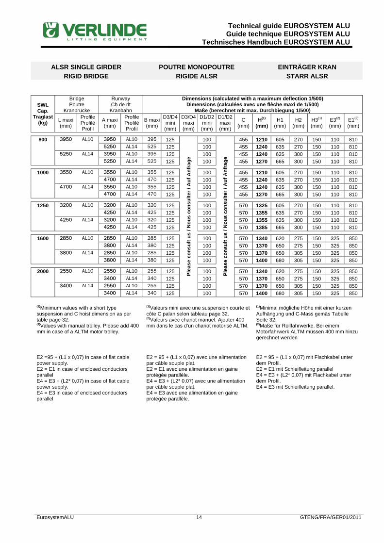
ALSR SINGLE GIRDER RIGID BRIDGE
POUTRE MONOPOUTRE RIGIDE ALSR
EINTRÄGER KRAN STARR ALSR
SWL Cap.
Traglast (kg)
Bridge Poutre
Kranbrücke
Runway Ch de rlt
Kranbahn
Dimensions (calculated with a maximum deflection 1/500) Dimensions (calculées avec une flèche maxi de 1/500)
Maße (berechnet mit max. Durchbiegung 1/500)
L maxi (mm)
Profile Profilé Profil
A maxi (mm)
Profile Profilé Profil
B maxi(mm)
D3/D4 mini (mm)
D3/D4 maxi (mm)
D1/D2 mini (mm)
D1/D2 maxi (mm)
C (mm)
H(1) (mm)
H1 (mm)
H2 (mm)
H3(1) (mm)
E3(2) (mm)
E1(2) (mm)
800 3950 AL10 3950 AL10 395 125
Plea
se c
onsu
lt us
/ N
ous
cons
ulte
r / A
uf A
nfra
ge
100
Plea
se c
onsu
lt us
/ N
ous
cons
ulte
r / A
uf A
nfra
ge
455 1210 605 270 150 110 810 5250 AL14 525 125 100 455 1240 635 270 150 110 810 5250 AL14 3950 AL10 395 125 100 455 1240 635 300 150 110 810 5250 AL14 525 125 100 455 1270 665 300 150 110 810
1000 3550 AL10 3550 AL10 355 125 100 455 1210 605 270 150 110 810
4700 AL14 470 125 100 455 1240 635 270 150 110 810 4700 AL14 3550 AL10 355 125 100 455 1240 635 300 150 110 810 4700 AL14 470 125 100 455 1270 665 300 150 110 810
1250 3200 AL10 3200 AL10 320 125 100 570 1325 605 270 150 110 810
4250 AL14 425 125 100 570 1355 635 270 150 110 810 4250 AL14 3200 AL10 320 125 100 570 1355 635 300 150 110 810 4250 AL14 425 125 100 570 1385 665 300 150 110 810
1600 2850 AL10 2850 AL10 285 125 100 570 1340 620 275 150 325 850
3800 AL14 380 125 100 570 1370 650 275 150 325 850 3800 AL14 2850 AL10 285 125 100 570 1370 650 305 150 325 850 3800 AL14 380 125 100 570 1400 680 305 150 325 850
2000 2550 AL10 2550 AL10 255 125 100 570 1340 620 275 150 325 850
3400 AL14 340 125 100 570 1370 650 275 150 325 850 3400 AL14 2550 AL10 255 125 100 570 1370 650 305 150 325 850 3400 AL14 340 125 100 570 1400 680 305 150 325 850
(1)Minimum values with a short type suspension and C hoist dimension as per table page 32. (2)Values with manual trolley. Please add 400 mm in case of a ALTM motor trolley.
(1)Valeurs mini avec une suspension courte et côte C palan selon tableau page 32. (2)Valeurs avec chariot manuel. Ajouter 400 mm dans le cas d’un chariot motorisé ALTM.
(1)Minimal mögliche Höhe mit einer kurzen Aufhängung und C-Mass gemäs Tabelle Seite 32. (2)Maße für Rollfahrwerke. Bei einem Motorfahrwerk ALTM müssen 400 mm hinzu gerechnet werden
E2 =95 + (L1 x 0,07) in case of flat cable power supply. E2 = E1 in case of enclosed conductors parallel E4 = E3 + (L2* 0,07) in case of flat cable power supply. E4 = E3 in case of enclosed conductors parallel
E2 = 95 + (L1 x 0,07) avec une alimentation par câble souple plat. E2 = E1 avec une alimentation en gaine protégée parallèle. E4 = E3 + (L2* 0,07) avec une alimentation par câble souple plat. E4 = E3 avec une alimentation en gaine protégée parallèle.
E2 = 95 + (L1 x 0,07) mit Flachkabel unter dem Profil. E2 = E1 mit Schleifleitung parallel E4 = E3 + (L2* 0,07) mit Flachkabel unter dem Profil. E4 = E3 mit Schleifleitung parallel.

Technical guide EUROSYSTEM ALUGuide technique EUROSYSTEM ALU
Technisches Handbuch EUROSYSTEM ALU
EurosystemALU 15 GTENG/FRA/GER01/2011
ALSL SINGLE GIRDER LOW HEADROOM BRIDGE
POUTRE MONOPOUTRE ENCASTREE ALSL
EINTRÄGER KRAN KURZE BAUHÖHE ALSL

Technical guide EUROSYSTEM ALUGuide technique EUROSYSTEM ALU
Technisches Handbuch EUROSYSTEM ALU
EurosystemALU 16 GTENG/FRA/GER01/2011
ALSL SINGLE GIRDER LOW HEADROOM BRIDGE
POUTRE MONOPOUTRE ENCASTREE ALSL
EINTRÄGER KRAN KURZE BAUHÖHE ALSL
SWL Cap.
Traglast (kg)
Bridge Poutre
Kranbrücke
Runway Ch de rlt
Kranbahn
Dimensions (calculated with a maximum deflection 1/500) Dimensions (calculées avec une flèche maxi de 1/500)
Maße (berechnet mit max. Durchbiegung 1/500)
L maxi (mm)
Profile Profilé Profil
A maxi (mm)
Profile Profilé Profil
B maxi(mm)
D3/D4 mini (mm)
D3/D4 maxi (mm)
D1/D2 mini (mm)
D1/D2 maxi (mm)
C (mm)
H(1) (mm)
H1 (mm)
H2 (mm)
H3(1) (mm)
E3(2) (mm)
E1(2) (mm)
63 6450 AL06 6250 AL06 625
Not
app
licab
le /
Non
app
licab
le /
Nic
ht a
nwen
dar
Not
app
licab
le /
Non
app
licab
le /
Nic
ht a
nwen
dar
100
Plea
se c
onsu
lt us
/ N
ous
cons
ulte
r / A
uf A
nfra
ge
310 640 180 175 150 125 532
8700 AL08 870 100 310 690 230 175 150 125 532
8700 AL10 870 100 310 730 270 175 150 125 545
8700 AL14 870 100 310 760 300 175 150 125 545
8700 AL08 8700 AL08 870 100 310 690 230 225 150 125 532
8700 AL10 870 100 310 730 270 225 150 125 545
8700 AL14 870 100 310 765 305 225 150 125 545
10200 AL10 8700 AL10 870 100 310 735 275 270 150 135 545
8700 AL14 870 100 310 765 305 270 150 135 545
8700 AL14 8700 AL10 870 100 310 735 275 300 150 135 545
8700 AL14 870 100 310 765 305 300 150 135 545
80 5950 AL06 5750 AL06 575 100 310 640 180 175 150 125 532
8300 AL08 830 100 310 690 230 175 150 125 532
8700 AL10 870 100 310 730 270 175 150 125 545
8700 AL14 870 100 310 760 300 175 150 125 545
8500 AL08 8300 AL08 830 100 310 690 230 225 150 125 532
8700 AL10 870 100 310 735 275 225 150 125 545
8700 AL14 870 100 310 765 305 225 150 125 545
8700 AL10 8700 AL10 870 100 310 735 275 270 150 135 545
8700 AL14 870 100 310 765 305 270 150 135 545
8700 AL14 8700 AL10 870 100 310 735 275 300 150 135 545
8700 AL14 870 100 310 765 305 300 150 135 545
125 5050 AL06 4850 AL06 485 100 310 640 180 175 150 125 532
7200 AL08 720 100 310 690 230 175 150 125 532
8500 AL10 850 100 310 730 270 175 150 125 545
8700 AL14 870 100 310 760 300 175 150 125 545
7400 AL08 7200 AL08 720 100 310 690 230 225 150 125 532
8500 AL10 850 100 310 735 275 225 150 125 545
8700 AL14 870 100 310 765 305 225 150 125 545
8700 AL10 8500 AL10 850 100 310 735 275 270 150 135 545
8700 AL14 870 100 310 765 305 270 150 135 545
8700 AL14 8500 AL10 850 100 310 735 275 300 150 135 545
8700 AL14 870 100 310 765 305 300 150 135 545
160 4640 AL06 4440 AL06 444 100 334 664 180 175 150 125 532
6600 AL08 660 100 334 714 230 175 150 125 532
7850 AL10 785 100 334 754 270 175 150 125 545
8700 AL14 870 100 334 784 300 175 150 125 545
6800 AL08 6600 AL08 660 100 334 714 230 225 150 125 532
7850 AL10 785 100 334 759 275 225 150 125 545
8700 AL14 870 100 334 789 305 225 150 125 545
8050 AL10 7850 AL10 785 100 334 759 275 270 150 135 545
8700 AL14 870 100 334 789 305 270 150 135 545
8700 AL14 7850 AL10 785 100 334 759 275 300 150 135 545
8700 AL14 870 100 334 789 305 300 150 135 545

Technical guide EUROSYSTEM ALUGuide technique EUROSYSTEM ALU
Technisches Handbuch EUROSYSTEM ALU
EurosystemALU 17 GTENG/FRA/GER01/2011
ALSL SINGLE GIRDER LOW HEADROOM BRIDGE
POUTRE MONOPOUTRE ENCASTREE ALSL
EINTRÄGER KRAN KURZE BAUHÖHE ALSL
SWL Cap.
Traglast (kg)
Bridge Poutre
Kranbrücke
Runway Ch de rlt
Kranbahn
Dimensions (calculated with a maximum deflection 1/500) Dimensions (calculées avec une flèche maxi de 1/500)
Maße (berechnet mit max. Durchbiegung 1/500)
L maxi (mm)
Profile Profilé Profil
A maxi (mm)
Profile Profilé Profil
B maxi(mm)
D3/D4 mini (mm)
D3/D4 maxi (mm)
D1/D2 mini (mm)
D1/D2 maxi (mm)
C (mm)
H(1) (mm)
H1 (mm)
H2 (mm)
H3(1) (mm)
E3(2) (mm)
E1(2) (mm)
250 3800 AL06 3600 AL06 360
Not
app
licab
le /
Non
app
licab
le /
Nic
ht a
nwen
dar
Not
app
licab
le /
Non
app
licab
le /
Nic
ht a
nwen
dar
100
Plea
se c
onsu
lt us
/ N
ous
cons
ulte
r / A
uf A
nfra
ge
334 664 180 175 150 125 532
5500 AL08 550 100 334 714 230 175 150 125 532
6650 AL10 665 100 334 754 270 175 150 125 545
8450 AL14 845 100 334 784 300 175 150 125 545
5700 AL08 5500 AL08 550 100 334 714 230 225 150 125 532
6650 AL10 665 100 334 759 275 225 150 125 545
8450 AL14 845 100 334 789 305 225 150 125 545
6850 AL10 6650 AL10 665 100 334 759 275 270 150 135 545
8450 AL14 845 100 334 789 305 270 150 135 545
8650 AL14 6650 AL10 665 100 334 759 275 300 150 135 545
8450 AL14 845 100 334 789 305 300 150 135 545
320 3400 AL06 3200 AL06 320 100 403 733 180 180 150 125 532
4950 AL08 495 100 403 783 230 180 150 125 532
6000 AL10 600 100 403 823 270 180 150 125 545
7700 AL14 770 100 403 853 300 180 150 125 545
5150 AL08 4950 AL08 495 100 403 783 230 230 150 125 532
6000 AL10 600 100 403 828 275 230 150 125 545
7700 AL14 770 100 403 858 305 230 150 125 545
6200 AL10 6000 AL10 600 100 403 828 275 275 150 135 545
7700 AL14 770 100 403 858 305 275 150 135 545
7900 AL14 6000 AL10 600 100 403 828 275 305 150 135 545
7700 AL14 770 100 403 858 305 305 150 135 545
400 4700 AL08 4500 AL08 450 100 403 783 230 225 150 125 532
5500 AL10 550 100 403 828 275 225 150 125 545
7100 AL14 710 100 403 858 305 225 150 125 545
5700 AL10 5500 AL10 550 100 403 828 275 270 150 135 545
7100 AL14 710 100 403 858 305 270 150 135 545
7300 AL14 5500 AL10 550 100 403 828 275 300 150 135 545
7100 AL14 710 100 403 858 305 300 150 135 545
500 4250 AL08 4050 AL08 405 100 403 783 230 230 150 125 532
4950 AL10 495 100 403 828 275 230 150 125 545
6450 AL14 645 100 403 858 305 230 150 125 545
5150 AL10 4950 AL10 495 100 403 828 275 275 150 135 545
6450 AL14 645 100 403 858 305 275 150 135 545
6650 AL14 4950 AL10 495 100 403 828 275 305 150 135 545
6450 AL14 645 100 403 858 305 305 150 135 545
630 4650 AL10 4450 AL10 445 100 455 880 275 270 150 135 545
5850 AL14 585 100 455 910 305 270 150 135 545
6050 AL14 4450 AL10 445 100 455 880 275 300 150 135 545
5850 AL14 585 100 455 910 305 300 150 135 545

Technical guide EUROSYSTEM ALUGuide technique EUROSYSTEM ALU
Technisches Handbuch EUROSYSTEM ALU
EurosystemALU 18 GTENG/FRA/GER01/2011
ALSL SINGLE GIRDER LOW HEADROOM BRIDGE
POUTRE MONOPOUTRE ENCASTREE ALSL
EINTRÄGER KRAN KURZE BAUHÖHE ALSL
SWL Cap.
Traglast (kg)
Bridge Poutre
Kranbrücke
Runway Ch de rlt
Kranbahn
Dimensions (calculated with a maximum deflection 1/500) Dimensions (calculées avec une flèche maxi de 1/500)
Maße (berechnet mit max. Durchbiegung 1/500)
L maxi (mm)
Profile Profilé Profil
A maxi (mm)
Profile Profilé Profil
B maxi(mm)
D3/D4 mini (mm)
D3/D4 maxi (mm)
D1/D2 mini (mm)
D1/D2 maxi (mm)
C (mm)
H(1) (mm)
H1 (mm)
H2 (mm)
H3(1) (mm)
E3(2) (mm)
E1(2) (mm)
800 4150 AL10 3950 AL10 395
Not
app
licab
le /
Non
app
licab
le /
Nic
ht a
nwen
dar
Not
app
licab
le /
Non
app
licab
le /
Nic
ht a
nwen
dar
100
Plea
se c
onsu
lt us
/ N
ous
cons
ulte
r / A
uf A
nfra
ge
455 880 275 270 150 135 545
5250 AL14 525 100 455 910 305 270 150 135 545
5450 AL14 3950 AL10 395 100 455 880 275 300 150 135 545
5250 AL14 525 100 455 910 305 300 150 135 545
1000 3750 AL10 3550 AL10 355 100 455 880 275 270 150 135 545
4700 AL14 470 100 455 910 305 270 150 135 545
4900 AL14 3550 AL10 355 100 455 880 275 300 150 135 545
4700 AL14 470 100 455 910 305 300 150 135 545
1250 3400 AL10 3200 AL10 320 100 570 995 275 270 150 135 545
4250 AL14 425 100 570 1025 305 270 150 135 545
4450 AL14 3200 AL10 320 100 570 995 275 300 150 135 545
4250 AL14 425 100 570 1025 305 300 150 135 545
(1)Minimum values with a short type suspension and C hoist dimension as per table page 32. (2)Values with manual trolley. Please add 400 mm in case of a ALTM motor trolley.
(1)Valeurs mini avec une suspension courte et côte C palan selon tableau page 32. (2)Valeurs avec chariot manuel. Ajouter 400 mm dans le cas d’un chariot motorisé ALTM.
(1)Minimal mögliche Höhe mit einer kurzen Aufhängung und C-Mass gemäs Tabelle Seite 32. (2)Maße für Rollfahrwerke. Bei einem Motorfahrwerk ALTM müssen 400 mm hinzu gerechnet werden
E2 = E1+ (L1* 0,07) in case of flat cable power supply. E2 = E1 in case of enclosed conductors parallel E4 = E3 + (L2* 0,07) in case of flat cable power supply. E4 = E3 in case of enclosed conductors parallel
E2 = E1 + (L1* 0,07) avec une alimentation par câble souple plat. E2 = E1 avec une alimentation en gaine protégée parallèle. E4 = E3 + (L2* 0,07) avec une alimentation par câble souple plat. E4 = E3 avec une alimentation en gaine protégée parallèle.
E2 = E1 + (L1* 0,07) mit Flachkabel unter dem Profil. E2 = E1 mit Schleifleitung parallel E4 = E3 + (L2* 0,07) mit Flachkabel unter dem Profil. E4 = E3 mit Schleifleitung parallel.
Technical guide EUROSYSTEM ALUGuide technique EUROSYSTEM ALU
Technisches Handbuch EUROSYSTEM ALU
EurosystemALU 19 GTENG/FRA/GER01/2011
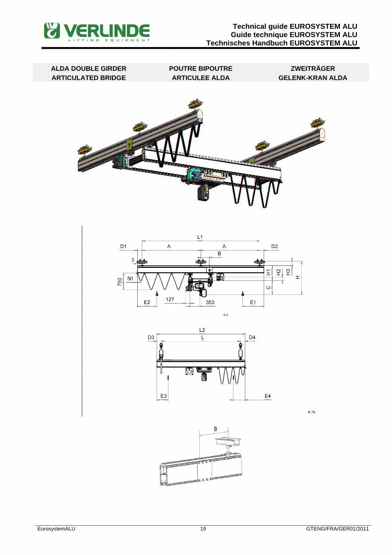
ALDA DOUBLE GIRDER ARTICULATED BRIDGE
POUTRE BIPOUTRE ARTICULEE ALDA
ZWEITRÄGER GELENK-KRAN ALDA

Technical guide EUROSYSTEM ALUGuide technique EUROSYSTEM ALU
Technisches Handbuch EUROSYSTEM ALU
EurosystemALU 20 GTENG/FRA/GER01/2011
ALDA DOUBLE GIRDER ARTICULATED BRIDGE
POUTRE BIPOUTRE ARTICULEE ALDA
ZWEITRÄGER GELENK-KRAN ALDA
SWL Cap.
Traglast (kg)
Bridge Poutre
Kranbrücke
Runway Ch de rlt
Kranbahn
Dimensions (calculated with a maximum deflection 1/500) Dimensions (calculées avec une flèche maxi de 1/500)
Maße (berechnet mit max. Durchbiegung 1/500)
L maxi (mm)
Profile Profilé Profil
A maxi (mm)
Profile Profilé Profil
B maxi(mm)
D3/D4 mini (mm)
D3/D4 maxi (mm)
D1/D2 mini (mm)
D1/D2 maxi (mm)
C (mm)
H(1) (mm)
H1 (mm)
H2 (mm)
H3(1) (mm)
E3(2) (mm)
E1(2) (mm)
63 7850 AL06 6250 AL06 625 100
Plea
se c
onsu
lt us
/ N
ous
cons
ulte
r / A
uf A
nfra
ge
100
Plea
se c
onsu
lt us
/ N
ous
cons
ulte
r / A
uf A
nfra
ge
310 690 230 -3 150 325 400
8700 AL08 870 100 100 310 740 280 -3 150 325 400
8700 AL10 870 100 100 310 785 325 -3 150 325 400
8700 AL14 870 100 100 310 820 360 -3 150 325 400
8700 AL08 8700 AL08 870 100 100 310 790 330 50 150 325 400
8700 AL10 870 100 100 310 835 375 50 150 325 400
8700 AL14 870 100 100 310 865 405 50 150 325 400
8700 AL10 8700 AL10 870 100 100 310 885 425 100 150 330 460
8700 AL14 870 100 100 310 920 460 100 150 330 460
8700 AL14 8700 AL10 870 100 100 310 920 460 130 150 330 460
8700 AL14 870 100 100 310 950 490 130 150 330 460
80 7200 AL06 5750 AL06 575 100 100 310 690 230 -3 150 325 400
8300 AL08 830 100 100 310 740 280 -3 150 325 400
8700 AL10 870 100 100 310 785 325 -3 150 325 400
8700 AL14 870 100 100 310 820 360 -3 150 325 400
8700 AL08 8300 AL08 830 100 100 310 790 330 50 150 325 400
8700 AL10 870 100 100 310 835 375 50 150 325 400
8700 AL14 870 100 100 310 865 405 50 150 325 400
8700 AL10 8700 AL10 870 100 100 310 885 425 100 150 330 460
8700 AL14 870 100 100 310 920 460 100 150 330 460
8700 AL14 8700 AL10 870 100 100 310 920 460 130 150 330 460
8700 AL14 870 100 100 310 950 490 130 150 330 460
125 6100 AL06 4850 AL06 485 100 100 310 690 230 -3 150 325 400
7200 AL08 720 100 100 310 740 280 -3 150 325 400
8500 AL10 850 100 100 310 785 325 -3 150 325 400
8700 AL14 870 100 100 310 820 360 -3 150 325 400
8700 AL08 7200 AL08 720 100 100 310 790 330 50 150 325 400
8500 AL10 850 100 100 310 835 375 50 150 325 400
8700 AL14 870 100 100 310 865 405 50 150 325 400
8700 AL10 8500 AL10 850 100 100 310 885 425 100 150 330 460
8700 AL14 870 100 100 310 920 460 100 150 330 460
8700 AL14 8500 AL10 850 100 100 310 920 460 130 150 330 460
8700 AL14 870 100 100 310 950 490 130 150 330 460
160 5550 AL06 4440 AL06 444 100 100 334 714 230 -3 150 325 400
6600 AL08 660 100 100 334 764 280 -3 150 325 400
7850 AL10 785 100 100 334 809 325 -3 150 325 400
8700 AL14 870 100 100 334 844 360 -3 150 325 400
8250 AL08 6600 AL08 660 100 100 334 814 330 50 150 325 400
7850 AL10 785 100 100 334 859 375 50 150 325 400
8700 AL14 870 100 100 334 889 405 50 150 325 400
8700 AL10 7850 AL10 785 100 100 334 909 425 100 150 330 460
8700 AL14 870 100 100 334 944 460 100 150 330 460
8700 AL14 7850 AL10 785 100 100 334 944 460 130 150 330 460
8700 AL14 870 100 100 334 974 490 130 150 330 460
Technical guide EUROSYSTEM ALUGuide technique EUROSYSTEM ALU
Technisches Handbuch EUROSYSTEM ALU
EurosystemALU 21 GTENG/FRA/GER01/2011
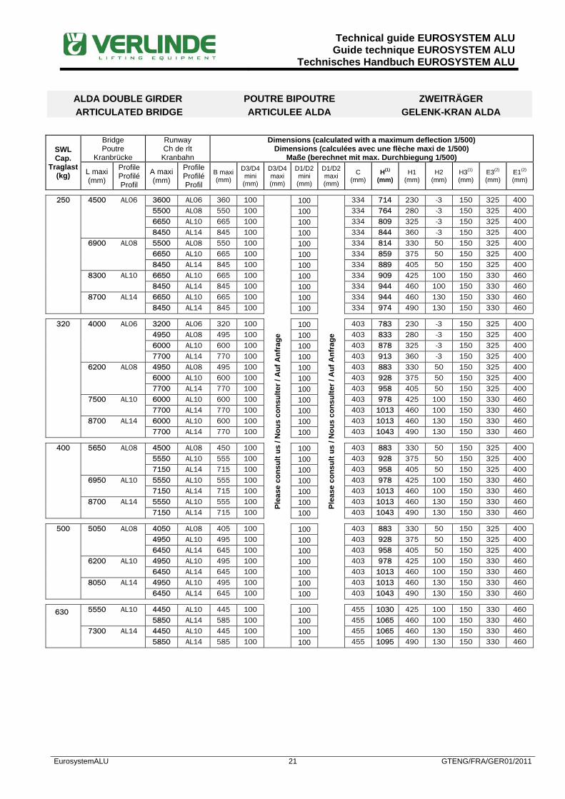
ALDA DOUBLE GIRDER ARTICULATED BRIDGE
POUTRE BIPOUTRE ARTICULEE ALDA
ZWEITRÄGER GELENK-KRAN ALDA
SWL Cap.
Traglast (kg)
Bridge Poutre
Kranbrücke
Runway Ch de rlt
Kranbahn
Dimensions (calculated with a maximum deflection 1/500) Dimensions (calculées avec une flèche maxi de 1/500)
Maße (berechnet mit max. Durchbiegung 1/500)
L maxi (mm)
Profile Profilé Profil
A maxi (mm)
Profile Profilé Profil
B maxi(mm)
D3/D4 mini (mm)
D3/D4 maxi (mm)
D1/D2 mini (mm)
D1/D2 maxi (mm)
C (mm)
H(1) (mm)
H1 (mm)
H2 (mm)
H3(1) (mm)
E3(2) (mm)
E1(2) (mm)
250 4500 AL06 3600 AL06 360 100
Plea
se c
onsu
lt us
/ N
ous
cons
ulte
r / A
uf A
nfra
ge
100
Plea
se c
onsu
lt us
/ N
ous
cons
ulte
r / A
uf A
nfra
ge
334 714 230 -3 150 325 400
5500 AL08 550 100 100 334 764 280 -3 150 325 400
6650 AL10 665 100 100 334 809 325 -3 150 325 400
8450 AL14 845 100 100 334 844 360 -3 150 325 400
6900 AL08 5500 AL08 550 100 100 334 814 330 50 150 325 400
6650 AL10 665 100 100 334 859 375 50 150 325 400
8450 AL14 845 100 100 334 889 405 50 150 325 400
8300 AL10 6650 AL10 665 100 100 334 909 425 100 150 330 460
8450 AL14 845 100 100 334 944 460 100 150 330 460
8700 AL14 6650 AL10 665 100 100 334 944 460 130 150 330 460
8450 AL14 845 100 100 334 974 490 130 150 330 460
320 4000 AL06 3200 AL06 320 100 100 403 783 230 -3 150 325 400
4950 AL08 495 100 100 403 833 280 -3 150 325 400
6000 AL10 600 100 100 403 878 325 -3 150 325 400
7700 AL14 770 100 100 403 913 360 -3 150 325 400
6200 AL08 4950 AL08 495 100 100 403 883 330 50 150 325 400
6000 AL10 600 100 100 403 928 375 50 150 325 400
7700 AL14 770 100 100 403 958 405 50 150 325 400
7500 AL10 6000 AL10 600 100 100 403 978 425 100 150 330 460
7700 AL14 770 100 100 403 1013 460 100 150 330 460
8700 AL14 6000 AL10 600 100 100 403 1013 460 130 150 330 460
7700 AL14 770 100 100 403 1043 490 130 150 330 460
400 5650 AL08 4500 AL08 450 100 100 403 883 330 50 150 325 400
5550 AL10 555 100 100 403 928 375 50 150 325 400
7150 AL14 715 100 100 403 958 405 50 150 325 400
6950 AL10 5550 AL10 555 100 100 403 978 425 100 150 330 460
7150 AL14 715 100 100 403 1013 460 100 150 330 460
8700 AL14 5550 AL10 555 100 100 403 1013 460 130 150 330 460
7150 AL14 715 100 100 403 1043 490 130 150 330 460
500 5050 AL08 4050 AL08 405 100 100 403 883 330 50 150 325 400
4950 AL10 495 100 100 403 928 375 50 150 325 400
6450 AL14 645 100 100 403 958 405 50 150 325 400
6200 AL10 4950 AL10 495 100 100 403 978 425 100 150 330 460
6450 AL14 645 100 100 403 1013 460 100 150 330 460
8050 AL14 4950 AL10 495 100 100 403 1013 460 130 150 330 460
6450 AL14 645 100 100 403 1043 490 130 150 330 460
630 5550 AL10 4450 AL10 445 100 100 455 1030 425 100 150 330 460
5850 AL14 585 100 100 455 1065 460 100 150 330 460
7300 AL14 4450 AL10 445 100 100 455 1065 460 130 150 330 460
5850 AL14 585 100 100 455 1095 490 130 150 330 460

Technical guide EUROSYSTEM ALUGuide technique EUROSYSTEM ALU
Technisches Handbuch EUROSYSTEM ALU
EurosystemALU 22 GTENG/FRA/GER01/2011
ALDA DOUBLE GIRDER ARTICULATED BRIDGE
POUTRE BIPOUTRE ARTICULEE ALDA
ZWEITRÄGER GELENK-KRAN ALDA
SWL Cap.
Traglast (kg)
Bridge Poutre
Kranbrücke
Runway Ch de rlt
Kranbahn
Dimensions (calculated with a maximum deflection 1/500) Dimensions (calculées avec une flèche maxi de 1/500)
Maße (berechnet mit max. Durchbiegung 1/500)
L maxi (mm)
Profile Profilé Profil
A maxi (mm)
Profile Profilé Profil
B maxi(mm)
D3/D4 mini (mm)
D3/D4 maxi (mm)
D1/D2 mini (mm)
D1/D2 maxi (mm)
C (mm)
H(1) (mm)
H1 (mm)
H2 (mm)
H3(1) (mm)
E3(2) (mm)
E1(2) (mm)
800 4950 AL10 3950 AL10 395 100
Plea
se c
onsu
lt us
/ N
ous
cons
ulte
r / A
uf A
nfra
ge
100
Plea
se c
onsu
lt us
/ N
ous
cons
ulte
r / A
uf A
nfra
ge
455 1030 425 100 150 330 460 5250 AL14 525 100 100 455 1065 460 100 150 330 460 6550 AL14 3950 AL10 395 100 100 455 1065 460 130 150 330 460 5250 AL14 525 100 100 455 1095 490 130 150 330 460
1000 4450 AL10 3550 AL10 355 100 100 455 1030 425 100 150 330 460
4700 AL14 470 100 100 455 1065 460 100 150 330 460 5900 AL14 3550 AL10 355 100 100 455 1065 460 130 150 330 460 4700 AL14 470 100 100 455 1095 490 130 150 330 460
1250 4000 AL10 3200 AL10 320 100 100 570 1145 425 100 150 330 460
4250 AL14 425 100 100 570 1180 460 100 150 330 460 5300 AL14 3200 AL10 320 100 100 570 1180 460 130 150 330 460 4250 AL14 425 100 100 570 1210 490 130 150 330 460
(1)Minimum values with a short type suspension and C hoist dimension as per table page 32. (2)Values with manual trolley. Please add 400 mm in case of a ALTM motor trolley.
(1)Valeurs mini avec une suspension courte et côte C palan selon tableau page 32. (2)Valeurs avec chariot manuel. Ajouter 400 mm dans le cas d’un chariot motorisé ALTM.
(1)Minimal mögliche Höhe mit einer kurzen Aufhängung und C-Mass gemäs Tabelle Seite 32. (2)Maße für Rollfahrwerke. Bei einem Motorfahrwerk ALTM müssen 400 mm hinzu gerechnet werden
E2 = E1+ (L1* 0,07) in case of flat cable power supply. E2 = E1 in case of enclosed conductors parallel E4 = E3 + (L2* 0,07) in case of flat cable power supply. E4 = E3 in case of enclosed conductors parallel
E2 = E1 + (L1* 0,07) avec une alimentation par câble souple plat. E2 = E1 avec une alimentation en gaine protégée parallèle. E4 = E3 + (L2* 0,07) avec une alimentation par câble souple plat. E4 = E3 avec une alimentation en gaine protégée parallèle.
E2 = E1 + (L1* 0,07) mit Flachkabel unter dem Profil. E2 = E1 mit Schleifleitung parallel E4 = E3 + (L2* 0,07) mit Flachkabel unter dem Profil. E4 = E3 mit Schleifleitung parallel.

Technical guide EUROSYSTEM ALUGuide technique EUROSYSTEM ALU
Technisches Handbuch EUROSYSTEM ALU
EurosystemALU 23 GTENG/FRA/GER01/2011
ALDR DOUBLE GIRDER RIGID BRIDGE
POUTRE BIPOUTRE RIGIDE ALDR
ZWEITRÄGER KRAN STARR ALDR
Technical guide EUROSYSTEM ALUGuide technique EUROSYSTEM ALU
Technisches Handbuch EUROSYSTEM ALU
EurosystemALU 24 GTENG/FRA/GER01/2011
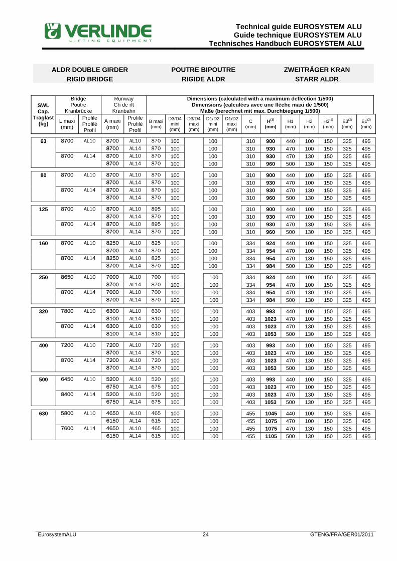
ALDR DOUBLE GIRDER
RIGID BRIDGE POUTRE BIPOUTRE
RIGIDE ALDRZWEITRÄGER KRAN
STARR ALDR
SWL Cap.
Traglast (kg)
Bridge Poutre
Kranbrücke
Runway Ch de rlt
Kranbahn
Dimensions (calculated with a maximum deflection 1/500) Dimensions (calculées avec une flèche maxi de 1/500)
Maße (berechnet mit max. Durchbiegung 1/500)
L maxi (mm)
Profile Profilé Profil
A maxi (mm)
Profile Profilé Profil
B maxi (mm)
D3/D4 mini (mm)
D3/D4 maxi (mm)
D1/D2 mini (mm)
D1/D2 maxi (mm)
C (mm)
H(1) (mm)
H1 (mm)
H2 (mm)
H3(1) (mm)
E3(2) (mm)
E1(2) (mm)
63 8700 AL10 8700 AL10 870 100
100
310 900 440 100 150 325 495 8700 AL14 870 100 100 310 930 470 100 150 325 495 8700 AL14 8700 AL10 870 100 100 310 930 470 130 150 325 495 8700 AL14 870 100 100 310 960 500 130 150 325 495
80 8700 AL10 8700 AL10 870 100 100 310 900 440 100 150 325 495
8700 AL14 870 100 100 310 930 470 100 150 325 495 8700 AL14 8700 AL10 870 100 100 310 930 470 130 150 325 495 8700 AL14 870 100 100 310 960 500 130 150 325 495
125 8700 AL10 8700 AL10 895 100 100 310 900 440 100 150 325 495
8700 AL14 870 100 100 310 930 470 100 150 325 495 8700 AL14 8700 AL10 895 100 100 310 930 470 130 150 325 495 8700 AL14 870 100 100 310 960 500 130 150 325 495
160 8700 AL10 8250 AL10 825 100 100 334 924 440 100 150 325 495
8700 AL14 870 100 100 334 954 470 100 150 325 495 8700 AL14 8250 AL10 825 100 100 334 954 470 130 150 325 495 8700 AL14 870 100 100 334 984 500 130 150 325 495
250 8650 AL10 7000 AL10 700 100 100 334 924 440 100 150 325 495
8700 AL14 870 100 100 334 954 470 100 150 325 495 8700 AL14 7000 AL10 700 100 100 334 954 470 130 150 325 495 8700 AL14 870 100 100 334 984 500 130 150 325 495
320 7800 AL10 6300 AL10 630 100 100 403 993 440 100 150 325 495
8100 AL14 810 100 100 403 1023 470 100 150 325 495 8700 AL14 6300 AL10 630 100 100 403 1023 470 130 150 325 495 8100 AL14 810 100 100 403 1053 500 130 150 325 495
400 7200 AL10 7200 AL10 720 100 100 403 993 440 100 150 325 495
8700 AL14 870 100 100 403 1023 470 100 150 325 495 8700 AL14 7200 AL10 720 100 100 403 1023 470 130 150 325 495 8700 AL14 870 100 100 403 1053 500 130 150 325 495
500 6450 AL10 5200 AL10 520 100 100 403 993 440 100 150 325 495
6750 AL14 675 100 100 403 1023 470 100 150 325 495 8400 AL14 5200 AL10 520 100
100
403 1023 470 130 150 325 495 6750 AL14 675 100 100 403 1053 500 130 150 325 495
630 5800 AL10 4650 AL10 465 100 100 455 1045 440 100 150 325 495
6150 AL14 615 100 100 455 1075 470 100 150 325 495 7600 AL14 4650 AL10 465 100 100 455 1075 470 130 150 325 495 6150 AL14 615 100 100 455 1105 500 130 150 325 495
Technical guide EUROSYSTEM ALUGuide technique EUROSYSTEM ALU
Technisches Handbuch EUROSYSTEM ALU
EurosystemALU 25 GTENG/FRA/GER01/2011
ALDR DOUBLE GIRDER RIGID BRIDGE
POUTRE BIPOUTRE RIGIDE ALDR
ZWEITRÄGER KRAN STARR ALDR
SWL Cap.
Traglast (kg)
Bridge Poutre
Kranbrücke
Runway Ch de rlt
Kranbahn
Dimensions (calculated with a maximum deflection 1/500) Dimensions (calculées avec une flèche maxi de 1/500)
Maße (berechnet mit max. Durchbiegung 1/500)
L maxi (mm)
Profile Profilé Profil
A maxi (mm)
Profile Profilé Profil
B maxi (mm)
D3/D4 mini (mm)
D3/D4 maxi (mm)
D1/D2 mini (mm)
D1/D2 maxi (mm)
C (mm)
H(1) (mm)
H1 (mm)
H2 (mm)
H3(1) (mm)
E3(2) (mm)
E1(2) (mm)
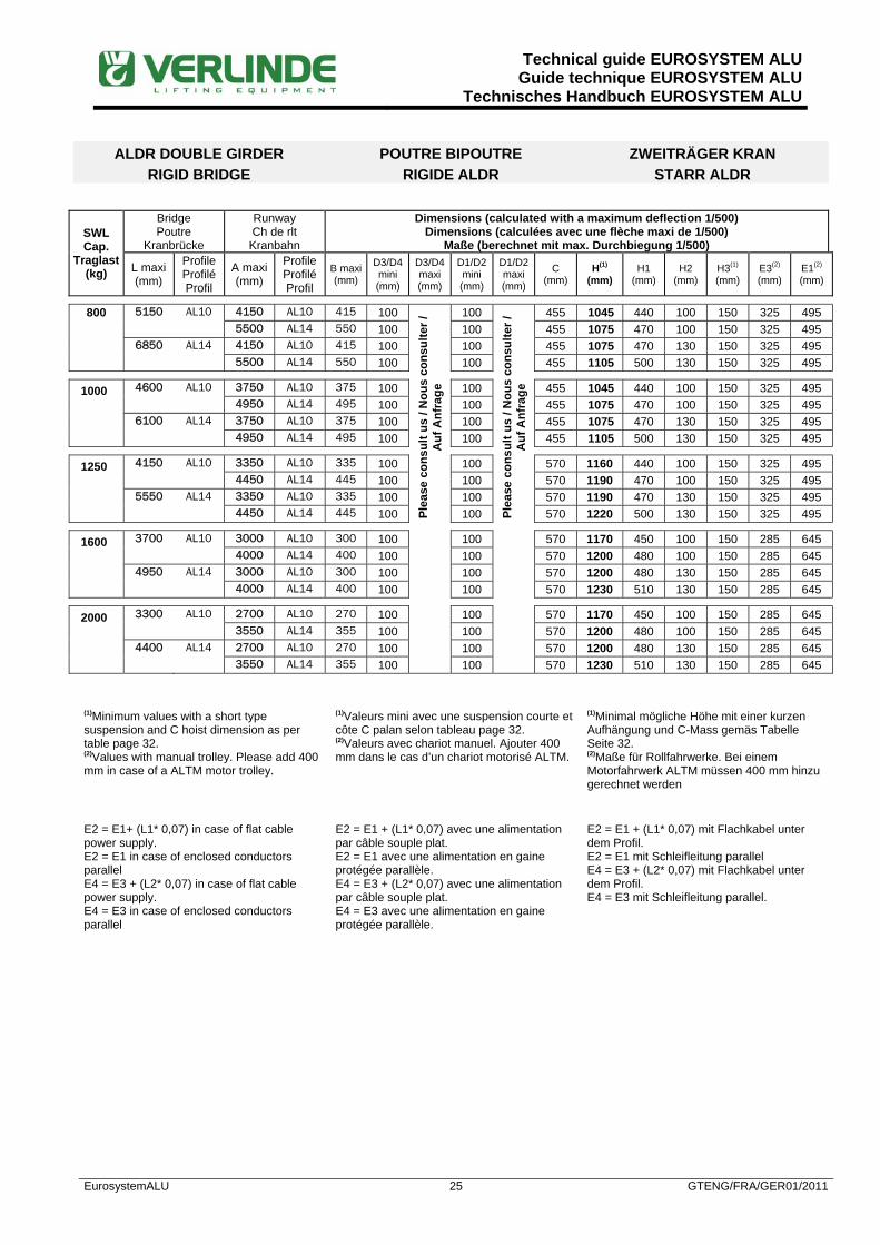
800 5150 AL10 4150 AL10 415 100
Plea
se c
onsu
lt us
/ N
ous
cons
ulte
r /
Auf
Anf
rage
100
Plea
se c
onsu
lt us
/ N
ous
cons
ulte
r /
Auf
Anf
rage
455 1045 440 100 150 325 495 5500 AL14 550 100 100 455 1075 470 100 150 325 495 6850 AL14 4150 AL10 415 100 100 455 1075 470 130 150 325 495 5500 AL14 550 100 100 455 1105 500 130 150 325 495
1000 4600 AL10 3750 AL10 375 100 100 455 1045 440 100 150 325 495
4950 AL14 495 100 100 455 1075 470 100 150 325 495 6100 AL14 3750 AL10 375 100 100 455 1075 470 130 150 325 495 4950 AL14 495 100 100 455 1105 500 130 150 325 495
1250 4150 AL10 3350 AL10 335 100 100 570 1160 440 100 150 325 495
4450 AL14 445 100 100 570 1190 470 100 150 325 495 5550 AL14 3350 AL10 335 100 100 570 1190 470 130 150 325 495 4450 AL14 445 100 100 570 1220 500 130 150 325 495
1600 3700 AL10 3000 AL10 300 100 100 570 1170 450 100 150 285 645
4000 AL14 400 100 100 570 1200 480 100 150 285 645 4950 AL14 3000 AL10 300 100 100 570 1200 480 130 150 285 645 4000 AL14 400 100 100 570 1230 510 130 150 285 645
2000 3300 AL10 2700 AL10 270 100 100 570 1170 450 100 150 285 645
3550 AL14 355 100 100 570 1200 480 100 150 285 645 4400 AL14 2700 AL10 270 100 100 570 1200 480 130 150 285 645 3550 AL14 355 100 100 570 1230 510 130 150 285 645
(1)Minimum values with a short type suspension and C hoist dimension as per table page 32. (2)Values with manual trolley. Please add 400 mm in case of a ALTM motor trolley.
(1)Valeurs mini avec une suspension courte et côte C palan selon tableau page 32. (2)Valeurs avec chariot manuel. Ajouter 400 mm dans le cas d’un chariot motorisé ALTM.
(1)Minimal mögliche Höhe mit einer kurzen Aufhängung und C-Mass gemäs Tabelle Seite 32. (2)Maße für Rollfahrwerke. Bei einem Motorfahrwerk ALTM müssen 400 mm hinzu gerechnet werden
E2 = E1+ (L1* 0,07) in case of flat cable power supply. E2 = E1 in case of enclosed conductors parallel E4 = E3 + (L2* 0,07) in case of flat cable power supply. E4 = E3 in case of enclosed conductors parallel
E2 = E1 + (L1* 0,07) avec une alimentation par câble souple plat. E2 = E1 avec une alimentation en gaine protégée parallèle. E4 = E3 + (L2* 0,07) avec une alimentation par câble souple plat. E4 = E3 avec une alimentation en gaine protégée parallèle.
E2 = E1 + (L1* 0,07) mit Flachkabel unter dem Profil. E2 = E1 mit Schleifleitung parallel E4 = E3 + (L2* 0,07) mit Flachkabel unter dem Profil. E4 = E3 mit Schleifleitung parallel.

Technical guide EUROSYSTEM ALUGuide technique EUROSYSTEM ALU
Technisches Handbuch EUROSYSTEM ALU
EurosystemALU 26 GTENG/FRA/GER01/2011
ALDL DOUBLE GIRDER LOW HEADROOM BRIDGE
POUTRE BIPOUTRE ENCASTREE ALDL
ZWEITRÄGER KRAN KURZE BAUHÖHE ALDL

Technical guide EUROSYSTEM ALUGuide technique EUROSYSTEM ALU
Technisches Handbuch EUROSYSTEM ALU
EurosystemALU 27 GTENG/FRA/GER01/2011
ALDL DOUBLE GIRDER LOW HEADROOM BRIDGE
POUTRE BIPOUTRE ENCASTREE ALDL
ZWEITRÄGER KRAN KURZE BAUHÖHE ALDL
SWL Cap.
Traglast (kg)
Bridge Poutre
Kranbrücke
Runway Ch de rlt
Kranbahn
Dimensions (calculated with a maximum deflection 1/500) Dimensions (calculées avec une flèche maxi de 1/500)
Maße (berechnet mit max. Durchbiegung 1/500)
L maxi (mm)
Profile Profilé Profil
A maxi (mm)
Profile Profilé Profil
B maxi(mm)
D3/D4 mini (mm)
D3/D4 maxi (mm)
D1/D2 mini (mm)
D1/D2 maxi (mm)
C (mm)
H(1) (mm)
H1 (mm)
H2 (mm)
H3(1) (mm)
E3(2) (mm)
E1(2) (mm)
63 8050 AL06 6250 AL06 625
Not
app
licab
le /
Non
app
licab
le /
Nic
ht a
nwen
dar
Not
app
licab
le /
Non
app
licab
le /
Nic
ht a
nwen
dar
100
Plea
se c
onsu
lt us
/ N
ous
cons
ulte
r / A
uf A
nfra
ge
310 463 3 -3 150 280 440
8700 AL08 870 100 310 515 55 -3 150 280 440
8700 AL10 870 100 310 555 95 -3 150 280 450
8700 AL14 870 100 310 585 125 -3 150 280 450
8700 AL08 8700 AL08 870 100 310 515 55 50 150 280 440
8700 AL10 870 100 310 555 95 50 150 280 450
8700 AL14 870 100 310 585 125 50 150 280 450
8700 AL10 8700 AL10 870 100 310 555 95 100 150 310 500
8700 AL14 870 100 310 585 125 100 150 310 500
8700 AL14 8700 AL10 870 100 310 570 110 130 150 310 500
8700 AL14 870 100 310 605 145 130 150 310 500
80 7400 AL06 5750 AL06 575 100 310 463 3 -3 150 280 440
8300 AL08 830 100 310 515 55 -3 150 280 440
8700 AL10 870 100 310 555 95 -3 150 280 450
8700 AL14 870 100 310 585 125 -3 150 280 450
8700 AL08 8300 AL08 830 100 310 515 55 50 150 280 440
8700 AL10 870 100 310 555 95 50 150 280 450
8700 AL14 870 100 310 585 125 50 150 280 450
8700 AL10 8700 AL10 870 100 310 555 95 100 150 310 500
8700 AL14 870 100 310 585 125 100 150 310 500
8700 AL14 8700 AL10 870 100 310 570 110 130 150 310 500
8700 AL14 870 100 310 605 145 130 150 310 500
125 6300 AL06 4850 AL06 485 100 310 463 3 -3 150 280 440
7200 AL08 720 100 310 515 55 -3 150 280 440
8500 AL10 850 100 310 555 95 -3 150 280 450
8700 AL14 870 100 310 585 125 -3 150 280 450
8700 AL08 7200 AL08 720 100 310 515 55 50 150 280 440
8500 AL10 850 100 310 555 95 50 150 280 450
8700 AL14 870 100 310 585 125 50 150 280 450
8700 AL10 8500 AL10 850 100 310 555 95 100 150 310 500
8700 AL14 870 100 310 585 125 100 150 310 500
8700 AL14 8500 AL10 850 100 310 570 110 130 150 310 500
8700 AL14 870 100 310 605 145 130 150 310 500
160 5750 AL06 4440 AL06 444 100 334 487 3 -3 150 280 440
6600 AL08 660 100 334 539 55 -3 150 280 440
7850 AL10 785 100 334 579 95 -3 150 280 450
8700 AL14 870 100 334 609 125 -3 150 280 450
8450 AL08 6600 AL08 660 100 334 539 55 50 150 280 440
7850 AL10 785 100 334 579 95 50 150 280 440
8700 AL14 870 100 334 609 125 50 150 280 440
8700 AL10 7850 AL10 785 100 334 579 95 100 150 310 500
8700 AL14 870 100 334 609 125 100 150 310 500
8700 AL14 7850 AL10 785 100 334 594 110 130 150 310 500
8700 AL14 870 100 334 629 145 130 150 310 500

Technical guide EUROSYSTEM ALUGuide technique EUROSYSTEM ALU
Technisches Handbuch EUROSYSTEM ALU
EurosystemALU 28 GTENG/FRA/GER01/2011
ALDL DOUBLE GIRDER LOW HEADROOM BRIDGE
POUTRE BIPOUTRE ENCASTREE ALDL
ZWEITRÄGER KRAN KURZE BAUHÖHE ALDL
SWL Cap.
Traglast (kg)
Bridge Poutre
Kranbrücke
Runway Ch de rlt
Kranbahn
Dimensions (calculated with a maximum deflection 1/500) Dimensions (calculées avec une flèche maxi de 1/500)
Maße (berechnet mit max. Durchbiegung 1/500)
L maxi (mm)
Profile Profilé Profil
A maxi (mm)
Profile Profilé Profil
B maxi(mm)
D3/D4 mini (mm)
D3/D4 maxi (mm)
D1/D2 mini (mm)
D1/D2 maxi (mm)
C (mm)
H(1) (mm)
H1 (mm)
H2 (mm)
H3(1) (mm)
E3(2) (mm)
E1(2) (mm)
250 4700 AL06 3600 AL06 360
Not
app
licab
le /
Non
app
licab
le /
Nic
ht a
nwen
dar
Not
app
licab
le /
Non
app
licab
le /
Nic
ht a
nwen
dar
100
Plea
se c
onsu
lt us
/ N
ous
cons
ulte
r / A
uf A
nfra
ge
334 487 3 -3 150 280 440
5500 AL08 550 100 334 539 55 -3 150 280 440
6650 AL10 665 100 334 579 95 -3 150 280 450
8450 AL14 845 100 334 609 125 -3 150 280 450
7100 AL08 5500 AL08 550 100 334 539 55 50 150 280 440
6650 AL10 665 100 334 579 95 50 150 280 450
8450 AL14 845 100 334 609 125 50 150 280 450
8500 AL10 6650 AL10 665 100 334 579 95 100 150 310 500
8450 AL14 845 100 334 609 125 100 150 310 500
8700 AL14 6650 AL10 665 100 334 594 110 130 150 310 500
8450 AL14 845 100 334 629 145 130 150 310 500
320 4200 AL06 3200 AL06 320 100 403 556 3 -3 150 280 440
4950 AL08 495 100 403 608 55 -3 150 280 450
6000 AL10 600 100 403 648 95 -3 150 280 450
7700 AL14 770 100 403 678 125 -3 150 280 440
6400 AL08 4950 AL08 495 100 403 608 55 50 150 280 440
6000 AL10 600 100 403 648 95 50 150 280 450
7700 AL14 770 100 403 678 125 50 150 280 450
7700 AL10 6000 AL10 600 100 403 648 95 100 150 310 500
7700 AL14 770 100 403 678 125 100 150 310 500
8700 AL14 6000 AL10 600 100 403 663 110 130 150 310 500
7700 AL14 770 100 403 698 145 130 150 310 500
400 5850 AL08 4500 AL08 450 100 403 608 55 50 150 280 440
5550 AL10 555 100 403 648 95 50 150 280 450
7150 AL14 715 100 403 678 125 50 150 280 450
7150 AL10 5550 AL10 555 100 403 648 95 100 150 310 500
7150 AL14 715 100 403 678 125 100 150 310 500
9700 AL14 5550 AL10 555 100 403 663 110 130 150 310 500
7150 AL14 715 100 403 698 145 130 150 310 500
500 5250 AL08 4050 AL08 405 100 403 608 55 50 150 280 440
4950 AL10 495 100 403 648 95 50 150 280 450
6450 AL14 645 100 403 678 125 50 150 280 450
6400 AL10 4950 AL10 495 100 403 648 95 100 150 310 500
6450 AL14 645 100 403 678 125 100 150 310 500
8250 AL14 4950 AL10 495 100 403 663 110 130 150 310 500
6450 AL14 645 100 403 698 145 130 150 310 500
630 5750 AL10 4450 AL10 445 100 455 700 95 100 150 310 500
5850 AL14 585 100 455 730 125 100 150 310 500
7500 AL14 4450 AL10 445 100 455 715 110 130 150 310 500
5850 AL14 585 100 455 750 145 130 150 310 500

Technical guide EUROSYSTEM ALUGuide technique EUROSYSTEM ALU
Technisches Handbuch EUROSYSTEM ALU
EurosystemALU 29 GTENG/FRA/GER01/2011
ALDL DOUBLE GIRDER LOW HEADROOM BRIDGE
POUTRE BIPOUTRE ENCASTREE ALDL
ZWEITRÄGER KRAN KURZE BAUHÖHE ALDL
SWL Cap.
Traglast (kg)
Bridge Poutre
Kranbrücke
Runway Ch de rlt
Kranbahn
Dimensions (calculated with a maximum deflection 1/500) Dimensions (calculées avec une flèche maxi de 1/500)
Maße (berechnet mit max. Durchbiegung 1/500)
L maxi (mm)
Profile Profilé Profil
A maxi (mm)
Profile Profilé Profil
B maxi(mm)
D3/D4 mini (mm)
D3/D4 maxi (mm)
D1/D2 mini (mm)
D1/D2 maxi (mm)
C (mm)
H(1) (mm)
H1 (mm)
H2 (mm)
H3(1) (mm)
E3(2) (mm)
E1(2) (mm)
800 5350 AL10 4150 AL10 415
Not
app
licab
le /
Non
app
licab
le /
Nic
ht a
nwen
dar
Not
app
licab
le /
Non
app
licab
le /
Nic
ht a
nwen
dar
100
Plea
se c
onsu
lt us
/ N
ous
cons
ulte
r / A
uf A
nfra
ge
455 700 95 100 150 310 500
5500 AL14 550 100 455 730 125 100 150 310 500
7100 AL14 4150 AL10 415 100 455 715 110 130 150 310 500
5500 AL14 550 100 455 750 145 130 150 310 500
1000 4800 AL10 3750 AL10 375 100 455 700 95 100 150 310 500
4950 AL14 495 100 455 730 125 100 150 310 500
6350 AL14 3750 AL10 375 100 455 715 110 130 150 310 500
4950 AL14 495 100 455 750 145 130 150 310 500
1250 4300 AL10 3350 AL10 335 100 570 815 95 100 150 310 500
4450 AL14 445 100 570 845 125 100 150 310 500
5750 AL14 3350 AL10 335 100 570 830 110 130 150 310 500
4450 AL14 445 100 570 865 145 130 150 310 500
(1)Minimum values with a short type suspension and C hoist dimension as per table page 32. (2)Values with manual trolley. Please add 400 mm in case of a ALTM motor trolley.
(1)Valeurs mini avec une suspension courte et côte C palan selon tableau page 32. (2)Valeurs avec chariot manuel. Ajouter 400 mm dans le cas d’un chariot motorisé ALTM.
(1)Minimal mögliche Höhe mit einer kurzen Aufhängung und C-Mass gemäs Tabelle Seite 32. (2)Maße für Rollfahrwerke. Bei einem Motorfahrwerk ALTM müssen 400 mm hinzu gerechnet werden
E2 = E1+ (L1* 0,07) in case of flat cable power supply. E2 = E1 in case of enclosed conductors parallel E4 = E3 + (L2* 0,07) in case of flat cable power supply. E4 = E3 in case of enclosed conductors parallel
E2 = E1 + (L1* 0,07) avec une alimentation par câble souple plat. E2 = E1 avec une alimentation en gaine protégée parallèle. E4 = E3 + (L2* 0,07) avec une alimentation par câble souple plat. E4 = E3 avec une alimentation en gaine protégée parallèle.
E2 = E1 + (L1* 0,07) mit Flachkabel unter dem Profil. E2 = E1 mit Schleifleitung parallel E4 = E3 + (L2* 0,07) mit Flachkabel unter dem Profil. E4 = E3 mit Schleifleitung parallel.

Technical guide EUROSYSTEM ALUGuide technique EUROSYSTEM ALU
Technisches Handbuch EUROSYSTEM ALU
EurosystemALU 30 GTENG/FRA/GER01/2011
ALM STRAIGHT MONORAIL MONORAIL DROIT ALM GERADE BAHN ALM
Technical guide EUROSYSTEM ALUGuide technique EUROSYSTEM ALU
Technisches Handbuch EUROSYSTEM ALU
EurosystemALU 31 GTENG/FRA/GER01/2011
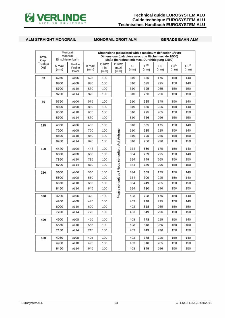
ALM STRAIGHT MONORAIL MONORAIL DROIT ALM GERADE BAHN ALM
SWL Cap.
Traglast (kg)
Monorail Monorail
Einschienenbahn
Dimensions (calculated with a maximum deflection 1/500) Dimensions (calculées avec une flèche maxi de 1/500)
Maße (berechnet mit max. Durchbiegung 1/500)
A maxi (mm)
Profile Profilé Profil
B maxi (mm)
D1/D2 mini (mm)
D1/D2 maxi (mm)
C (mm)
H(1) (mm)
H2 (mm)
H3(1) (mm)
E1(2) (mm)
63 6250 AL06 625 100
Plea
se c
onsu
lt us
/ N
ous
cons
ulte
r / A
uf A
nfra
ge
310 635 175 150 140
8800 AL08 880 100 310 685 225 150 140
8700 AL10 870 100 310 725 265 150 150
8700 AL14 870 100 310 756 296 150 150
80 5750 AL06 575 100 310 635 175 150 140
8300 AL08 830 100 310 685 225 150 140
9550 AL10 955 100 310 725 265 150 150
8700 AL14 870 100 310 756 296 150 150
125 4850 AL06 485 100 310 635 175 150 140
7200 AL08 720 100 310 685 225 150 140
8500 AL10 850 100 310 725 265 150 150
8700 AL14 870 100 310 756 296 150 150
160 4440 AL06 444 100 334 659 175 150 140
6600 AL08 660 100 334 709 225 150 140
7850 AL10 785 100 334 749 265 150 150
8700 AL14 870 100 334 780 296 150 150
250 3600 AL06 360 100 334 659 175 150 140
5500 AL08 550 100 334 709 225 150 140
6650 AL10 665 100 334 749 265 150 150
8450 AL14 845 100 334 780 296 150 150
320 3200 AL06 320 100 403 728 175 150 140
4950 AL08 495 100 403 778 225 150 140
6000 AL10 600 100 403 818 265 150 150
7700 AL14 770 100 403 849 296 150 150
400 4500 AL08 450 100 403 778 225 150 140
5550 AL10 555 100 403 818 265 150 150
7150 AL14 715 100 403 849 296 150 150
500 4050 AL08 405 100 403 778 225 150 140
4950 AL10 495 100 403 818 265 150 150
6450 AL14 645 100 403 849 296 150 150

Technical guide EUROSYSTEM ALUGuide technique EUROSYSTEM ALU
Technisches Handbuch EUROSYSTEM ALU
EurosystemALU 32 GTENG/FRA/GER01/2011
SWL Cap.
Traglast (kg)
Monorail Monorail
Einschienenbahn
Dimensions (calculated with a maximum deflection 1/500) Dimensions (calculées avec une flèche maxi de 1/500)
Maße (berechnet mit max. Durchbiegung 1/500)
A maxi (mm)
Profile Profilé Profil
B maxi (mm)
D1/D2 mini (mm)
D1/D2 maxi (mm)
C (mm)
H(1) (mm)
H2 (mm)
H3(1) (mm)
E1(2) (mm)
630 4450 AL10 445 100
Plea
se c
onsu
lt us
/ N
ous
cons
ulte
r / A
uf A
nfra
ge 455 870 265 150 150
5850 AL14 585 100 455 901 296 150 150
800 3950 AL10 395 100 455 870 265 150 150
5250 AL14 525 100 455 901 296 150 150
1000 3550 AL10 355 100 455 870 265 150 150
4700 AL14 470 100 455 901 296 150 150
1250 3200 AL10 320 100 570 985 265 150 150
4250 AL14 425 100 570 1016 296 150 150
1600 2850 AL10 285 100 570 990 270 150 325
3800 AL14 380 100 570 1020 300 150 325
2000 2550 AL10 255 100 570 990 270 150 325
3400 AL14 340 100 570 1020 300 150 325
(1)Minimum values with a short type suspension and C hoist dimension as per table page 32. (2)Values with manual trolley. Please add 400 mm in case of a ALTM motor trolley.
(1)Valeurs mini avec une suspension courte et côte C palan selon tableau page 32. (2)Valeurs avec chariot manuel. Ajouter 400 mm dans le cas d’un chariot motorisé ALTM.
(1)Minimal mögliche Höhe mit einer kurzen Aufhängung und C-Mass gemäs Tabelle Seite 32. (2)Maße für Rollfahrwerke. Bei einem Motorfahrwerk ALTM müssen 400 mm hinzu gerechnet werden
E2 = E1+ (L* 0,07) in case of flat cable power supply. E2 = E1 in case of enclosed conductors parallel.
E2 = E1 + (L* 0,07) avec une alimentation par câble souple plat. E2 = E1 avec une alimentation en gaine protégée parallèle.
E2 = E1 + (L* 0,07) mit Flachkabel unter dem Profil. E2 = E1 mit Schleifleitung parallel

Technical guide EUROSYSTEM ALUGuide technique EUROSYSTEM ALU
Technisches Handbuch EUROSYSTEM ALU
EurosystemALU 33 GTENG/FRA/GER01/2011
ELECTRIC CHAIN HOIST
EUROCHAIN VL PALAN ELECTRIQUE A CHAINE
EUROCHAIN VL ELEKTROKETTENZUG
EUROCHAIN VL The following table only shows the most popular chain hoists. For more information please see our leaflet "DIMENSIONS EUROCHAIN VL”. The dimensions given in the relevant tables are based on those particular hoists.
Le tableau ci-dessous ne présente que les palans les plus courants. Pour plus d’informations, consulter notre documentation “DIMENSIONS EUROCHAIN VL”. Les encombrements indiqués dans les tableaux sont basés sur ces modèles de palans.
Die folgende Tabelle zeigt die bevorzugten Kettenzüge. Für mehr Infos, beachten Sie bitte das technische Datenhandbuch zu unseren Kettenzügen EUROCHAIN VL. Die Abmessungen der kompletten Anlagen beziehen sich auf diese bestimmten Modelle.
Hoist type Palan modèle
Zug Modell
SWL Charge Traglast
(kg)
FEM FEM FEM
Speeds Vitesses Geschw. (m/min)
C (mm)
VL1 0616 b1 63 1 Bm 16/4 310
VL1 128 b1 125 1Bm 8/2 310
VL1 254 b1 250 1Bm 4/1 334
VL5 508 b1 500 1Bm 8/2 403
VL5 1004 b1 1000 1Bm 4/1 455
VL10 1604 b1 1600 1Bm 4/1 570
VL10 2004 b1 2000 1Bm 4/1 570
The EUROCHAIN chain hoists delivered with an EUROSYSTEM ALU installation are always supplied with plug-in facilities for the mains connection.
Dans tous les cas de figure les palans EUROCHAIN livrés avec un ensemble EUROSYSTEM ALU sont fournis avec une prise d’alimentation débrochable.
Die EUROCHAIN Kettenzüge, die zusammen mit einer EUROSYSTEM ALU Anlage geliefert werden, sind immer mit Steckverbindung für die Stromversorgung ausgerüstet.

Technical guide EUROSYSTEM ALUGuide technique EUROSYSTEM ALU
Technisches Handbuch EUROSYSTEM ALU
EurosystemALU 34 GTENG/FRA/GER01/2011
POWER FEEDING LINES LIGNES D’ALIMENTATION STROMZUFÜHRUNGEN There are 3 feeding solutions available : • Flat cable under the profile (fig. 1) • Enclosed conductors parallel (ifg. 2) • Inner conductors inside the profile AL14
(fig. 3)
3 types d’alimentation sont disponibles : • Câble plat sous le profilé (fig. 1) • Gaine protégée parallèle (fig. 2) • Conducteurs intégrés à l’intérieur du
profilé AL14 (fig. 3)
3 Typen stehen zur Auswahl: • Flachkabel unter dem Profil (Abb. 1) • Schleifleitung parallel zum Profil (Abb. 2) • Schleifleitung im Profil AL14 integriert
(Abb. 3)
Flat cable festoon systems comprise of flat cable supported by cable trolleys. These trolleys run inside of the profile. This solution is economical and ideal for light duty applications up to 35 m maximum length.
Les alimentations par câble sont réalisées à l’aide de câble plat supportés par des chariots porte-câble circulant dans le profilé UKA ou le rail C parallèle à celui-ci. Cette solution, peu onéreuse, est recommandée sur des longueurs de ligne de 35 m au maximum.
Die Flachkabel-Stromzuführung wird mit Hilfe von Flachkabeln und kleinen Fahrwerken realisiert, die entweder im Profil oder parallel zum Profil in einer C-Schiene fahren. Diese Lösung wird empfohlen für Längen bis zu maximal 35 m.
Longer flat cable systems require increased number of trolleys and can create problems with the bunching of the cables (about 7 % of the overall track length). We will recommend for these applications and also for multi-bridge systems to use a power feed by an enclosed conductor system parallel or the use of AL14 profile with inner conductors.
Au-delà de cette longueur, la voie de garage des chariots porte-câble risque de poser des problèmes d’encombrement (environ 7 % de la longueur d’une voie). Dans ce cas, ou pour l’alimentation simultanée de plusieurs ponts sur un même chemin de roulement, on préférera l’alimentation par gaine protégée parallèle ou intégrée dans le profilé AL14.
Lange Flachkabel-Stromzuführungen können Probleme bei der Anwendung hervorrufen, durch einen sehr langen Kabelbahnhof (ca. 7% der Gesamtlänge der Fahrbahn). In diesem Fall, oder wenn mehrere Einspeisungspunkte benötigt werden, empfehlen wir die Verwendung von einer Schleifleitung parallel oder integriert im Profil AL14.
Fig. 1 / Abb. 1 Fig. 2 / Abb. 2
AVAILABLE AT A LATER STAGE DISPONIBLE ULTERIEUREMENT
SPÄTER VERFÜGBAR
Fig. 3 / Abb. 3

Technical guide EUROSYSTEM ALUGuide technique EUROSYSTEM ALU
Technisches Handbuch EUROSYSTEM ALU
EurosystemALU 35 GTENG/FRA/GER01/2011
STRAIGHT PROFILES PROFILES DROITS GERADE PROFILE
Profile AL06 : Dimensions : 135 x 90 mm Weight : 6,5 kg / m Inertia : 501 cm4
Profilé AL06 : Dimensions : 135 x 90 mm Poids : 6,5 kg / m Inertie : 501 cm4
Profil AL06 : Abmessungen : 135 x 90 mm Gewicht : 6,5 kg / m Inertia : 501 cm4
Profile length Longueur du profilé
Profillänge (m)
Code Code
Bezeichnung
1 AL06P100
2 AL06P200
3 AL06P300
4 AL06P400
5 AL06P500
6 AL06P600
Profile AL08 : Dimensions : 185 x 90 mm Weight : 8,6 kg / m Inertia : 1253 cm4
Profilé AL08 : Dimensions : 185 x 90 mm Poids : 8,6 kg / m Inertie : 1253 cm4
Profil AL08 : Abmessungen : 185 x 90 mm Gewicht : 8,6 kg / m Inertia : 1253 cm4
Profile length Longueur du profilé
Profillänge (m)
Code Code
Bezeichnung
1 AL08P100
2 AL08P200
3 AL08P300
4 AL08P400
5 AL08P500
6 AL08P600
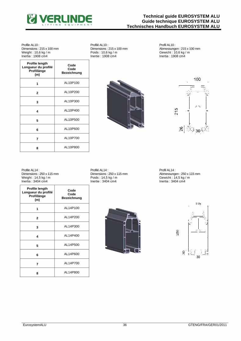
Technical guide EUROSYSTEM ALUGuide technique EUROSYSTEM ALU
Technisches Handbuch EUROSYSTEM ALU
EurosystemALU 36 GTENG/FRA/GER01/2011
Profile AL10 : Dimensions : 215 x 100 mm Weight : 10,6 kg / m Inertia : 1908 cm4
Profilé AL10 : Dimensions : 215 x 100 mm Poids : 10,6 kg / m Inertie : 1908 cm4
Profil AL10 : Abmessungen : 215 x 100 mm Gewicht : 10,6 kg / m Inertia : 1908 cm4
Profile length Longueur du profilé
Profillänge (m)
Code Code
Bezeichnung
1 AL10P100
2 AL10P200
3 AL10P300
4 AL10P400
5 AL10P500
6 AL10P600
7 AL10P700
8 AL10P800
Profile AL14 : Dimensions : 250 x 115 mm Weight : 14,5 kg / m Inertia : 3404 cm4
Profilé AL14 : Dimensions : 250 x 115 mm Poids : 14,5 kg / m Inertie : 3404 cm4
Profil AL14 : Abmessungen : 250 x 115 mm Gewicht : 14,5 kg / m Inertia : 3404 cm4
Profile length Longueur du profilé
Profillänge (m)
Code Code
Bezeichnung
1 AL14P100
2 AL14P200
3 AL14P300
4 AL14P400
5 AL14P500
6 AL14P600
7 AL14P700
8 AL14P800

Technical guide EUROSYSTEM ALUGuide technique EUROSYSTEM ALU
Technisches Handbuch EUROSYSTEM ALU
EurosystemALU 37 GTENG/FRA/GER01/2011
PROFILE CONNECTIONS LIAISONS ENTRE PROFILES PROFILVERBINDUNGEN
The design of our profile connections ensures a total safety after assembly. Also the fixing screws (4 at the top, 6 or 8 at the bottom of the plates), self-forming screws are added at site on each side of the plates, thus bringing to the system a “positive” safety and making opening impossible Tightening torques needed are engraved on the plates, which ensures a proper assembly and makes maintenance works easier. The reinforcement studs inserted inside the profiles before connecting them is an extra safety element.
La conception de nos plaques de liaison garantit une sécurité totale après montage. En plus des éléments de fixation par serrage (4 en partie supérieure, 6 ou 8 en partie inférieure), le montage sur site de vis auto-formeuses en extrémités inférieures des plaques amène une sécurité “positive” à l’ensemble, rendant impossible une ouverture ultérieure. La gravure sur les plaques des couples de serrage nécessaires garantit un montage aux normes et facilite les interventions de maintenance. L’utilisation des goujons de renfort à insérer dans les profilés avant montage des plaques est un élément supplémentaire de sécurité.
Die Konstruktion der Profilanschlüsse gewährleistet eine hohe Sicherheit nach der Montage. Neben den Befestigungs-schrauben (4 an der Oberseite, 6 oder 8 an der Unterseite der Platte), werden noch selbsschneidende Schrauben am Einsatzort an jeder Seite der Verbindungsplatte angebracht, dadurch wird das System Positiv sicher und macht das ein Öffnen der Profile unmöglich Die Anzugsdrehmomente sind auf den Platten eingraviert. Dies gewährleistet eine leichtere Instandhaltung sowie eine korrekte Montage. Die Verbindungsbolzen, die innerhalb der Profile eingesetzt werden, bieten eine zusätzliche Sicherheit.
Profile Profilé Profil
Connection Liaison
Verbindung
Code Code
Bezeichnung
AL06 Straight-Straight
Droit-Droit Gerade-Gerade
AL06E020
AL08 Straight-Straight
Droit-Droit Gerade-Gerade
AL08E020
AL10 Straight-Straight
Droit-Droit Gerade-Gerade
AL10E020
AL14 Straight-Straight
Droit-Droit Gerade-Gerade
AL14E020
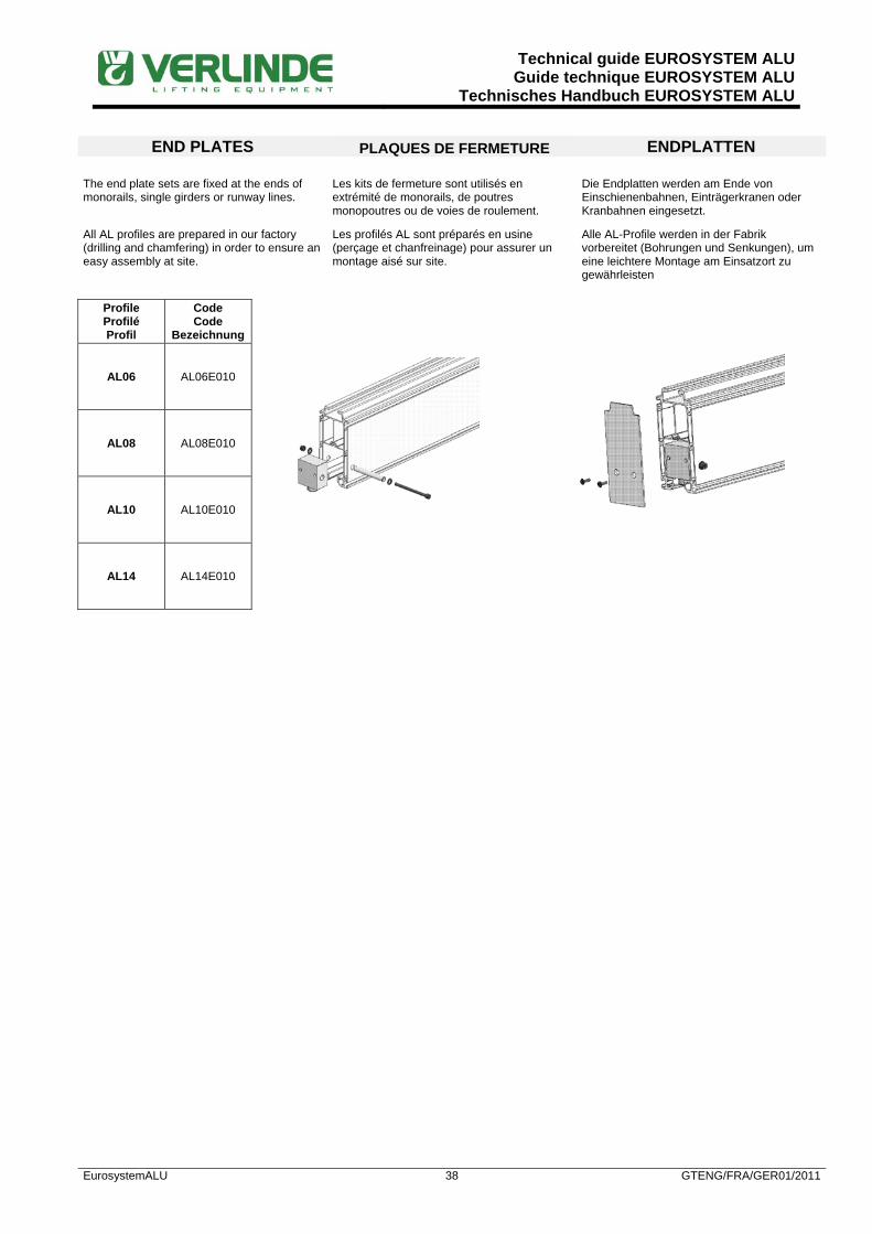
Technical guide EUROSYSTEM ALUGuide technique EUROSYSTEM ALU
Technisches Handbuch EUROSYSTEM ALU
EurosystemALU 38 GTENG/FRA/GER01/2011
END PLATES PLAQUES DE FERMETURE ENDPLATTEN
The end plate sets are fixed at the ends of monorails, single girders or runway lines.
Les kits de fermeture sont utilisés en extrémité de monorails, de poutres monopoutres ou de voies de roulement.
Die Endplatten werden am Ende von Einschienenbahnen, Einträgerkranen oder Kranbahnen eingesetzt.
All AL profiles are prepared in our factory (drilling and chamfering) in order to ensure an easy assembly at site.
Les profilés AL sont préparés en usine (perçage et chanfreinage) pour assurer un montage aisé sur site.
Alle AL-Profile werden in der Fabrik vorbereitet (Bohrungen und Senkungen), um eine leichtere Montage am Einsatzort zu gewährleisten
Profile Profilé Profil
Code Code
Bezeichnung
AL06 AL06E010
AL08 AL08E010
AL10 AL10E010
AL14 AL14E010

Technical guide EUROSYSTEM ALUGuide technique EUROSYSTEM ALU
Technisches Handbuch EUROSYSTEM ALU
EurosystemALU 39 GTENG/FRA/GER01/2011
SUSPENSIONS SUSPENSIONS AUFHÄNGUNGEN The suspensions represent an important part of a light crane system. Their articulated construction minimizes the horizontal stresses transmitted to the building structure.
Les suspensions constituent un élément essentiel d’un système de manutention. Leur conception articulée minimise les efforts transmis aux structures porteuses des bâtiments.
Die Aufhängungen sind ein wichtiger Baustein des Leichtbaukranes. Die flexiblen Aufhängungen reduzieren die zu übertragenden Kräfte auf die tragende Struktur.
They are adjusted on site by a simple cutting at length according to the building configuration. They compensate the possible unevenness of the building structure.
Elles sont réglables sur site par simple coupe à longueur selon la configuration du bâtiment. Elles permettent de compenser les irrégularités possibles de la structure porteuse.
Sie können leicht auf die passende Länge zugeschnitten werden. Sie erlauben eine leichte Anpassung an die tragende Struktur.
The suspensions are available in different sizes depending on the existing structures and can be connected to any I or H beam or straight to a ceiling or a wall.
Les suspensions sont disponibles en différentes largeurs adaptées aux structures existantes et se fixent sous tout type de profilés I ou H ou directement sous plafond ou en applique.
Die Aufhängungen sind in verschiedenen Ausführungen und Breiten lieferbar, für sämtliche handelsüblichen Profile, zur Befestigung direkt unter die Decke oder als Wandbefestigungen.
The 3 tables hereafter summarize the calculations of the quantities of suspensions required depending on the working conditions and the profile sizes.
Les 3 tableaux ci-après résument les modes de calcul des quantités de suspensions nécessaires selon les conditions d’environnement et les tailles des profilés.
Die 3 untenstehenden Tabellen zeigen die Anzahl der benötigten Aufhängungen je nach Ausführung und Profilgrösse.

Technical guide EUROSYSTEM ALUGuide technique EUROSYSTEM ALU
Technisches Handbuch EUROSYSTEM ALU
EurosystemALU 40 GTENG/FRA/GER01/2011
SELECTION OF THE SUSPENSIONS FOR A RUNWAY AL06 OR AL08 SELECTION DES SUSPENSIONS POUR UN CHEMIN DE ROULEMENT AL06 OU AL08 AUSWAHL DER AUFHÄNGUNGEN FÜR EINE KRANBAHN AL06 ODER AL08
Suspension / Suspension / Aufhängung H3 < 350 mm (500 kg maximum)
350 mm < H3 < 1000 mm (500 kg maximum)
H3 > 1000 mm (500 kg maximum) Type / Type Code / Code
Short / Courte / Kurz AL14R 010 / 020 / 050 Yes / Oui / Ja No / Non / Nein No / Non / Nein
Long / Longue / Lang AL14R 030 / 040 / 060 Yes / Oui / Ja Yes / Oui / Ja Yes / Oui / Ja
Longitudinal side support Support longitudinal Querverstrebung in
Längsrichtung
AL14R 070 No / Non / Nein 1 per runway line
1 par file 1 an jeder Seite
1 at each end 1 à chaque extrémité
1 an jedem Ende
Lateral side support Support transversal Querverstrebung in
Querrichtung
AL14R 070 No / Non / Nein
1 at each end + 1 every 10 m
1 à chaque extrémité + 1 tous les 10 m 1 an jedem Ende
+ 1 jede 10 m
2 at each end + 2 every 10 m
2 à chaque extrémité + 2 tous les 10 m 2 an jedem Ende
+ 2 jede 10 m
Extension set 500 mm Kit d'extension 500 mm Verlängerung 500 mm
ES4R 080 ES4R 085 No / Non / Nein
1 per suspension + 1 or more per side support
1 par suspension + 1 ou plus par oblique
1 je Aufhängung + 1 oder mehr je Querverstrebung
1 or 2 per suspension + 2 or more per side support
1 ou 2 par suspension + 1 ou plus par oblique 1 oder 2 je Aufhängung
+ 1 oder mehr je Querverstrebung
Maximum distance between connections and suspensions : No limit The relevant fixings must be selected in addition to the side supports.
Distance maximum entre jonctions et suspensions : Pas de limite Ajouter aux suspensions obliques les fixations correspondantes.
Abstand zwischen Profilverbindung und Aufhängung : keine Begrenzung Die entsprechenden Befestigungen für Querverstrebungen müssen zusätzlich ausgewählt werden.
SELECTION OF THE SUSPENSIONS FOR A RUNWAY AL10 SELECTION DES SUSPENSIONS POUR UN CHEMIN DE ROULEMENT AL10 AUSWAHL DER AUFHÄNGUNGEN FÜR EINE KRANBAHN AL10
Suspension / Suspension / Aufhängung H3 < 350 mm Max = 2000 kg
350 mm < H3 < 1000 mm (500 kg maximum)
H3 > 1000 mm (500 kg maximum)
350 mm < H3 < 700 mm (1000 kg maximum)
H3 > 700 mm (1000 kg maximum)
Type / Type Code / Code 350 mm < H3 < 500 mm (2000 kg maximum)
H3 > 500 mm (2000 kg maximum)
Short / Courte / Kurz AL14R 010 / 020 / 050 Yes / Oui / Ja No / Non / Nein No / Non / Nein
Long / Longue / Lang AL14R 030 / 040 / 060 Yes / Oui / Ja Yes / Oui / Ja Yes / Oui / Ja
Longitudinal side support Support longitudinal Querverstrebung in
Längsrichtung
AL14R 070 No / Non / Nein 1 per runway line
1 par file 1 an jeder Seite
1 at each end 1 à chaque extrémité
1 an jedem Ende
Lateral side support Support transversal Querverstrebung in
Querrichtung
AL14R 070 No / Non / Nein
1 at each end + 1 every 15 m
1 à chaque extrémité + 1 tous les 15 m 1 an jedem Ende
+ 1 jede 15 m
2 at each end + 2 every 15 m
2 à chaque extrémité + 2 tous les 15 m 2 an jedem Ende
+ 2 jede 15 m
Extension set 500 mm Kit d'extension 500 mm Verlängerung 500 mm
ES4R 080 ES4R 085 No / Non / Nein
1 per suspension + 1 or more per side support
1 par suspension + 1 ou plus par oblique
1 je Aufhängung + 1 oder mehr je Querverstrebung
1 or 2 per suspension + 2 or more per side support
1 ou 2 par suspension + 1 ou plus par oblique 1 oder 2 je Aufhängung
+ 1 oder mehr je Querverstrebung
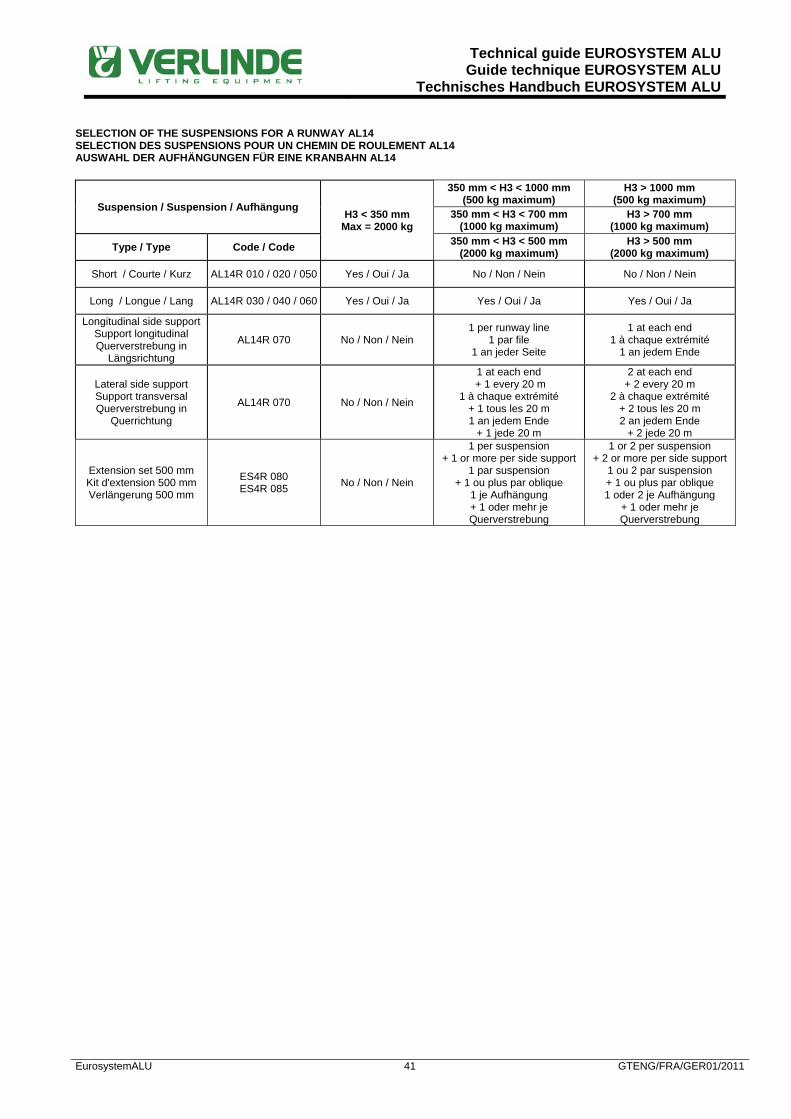
Technical guide EUROSYSTEM ALUGuide technique EUROSYSTEM ALU
Technisches Handbuch EUROSYSTEM ALU
EurosystemALU 41 GTENG/FRA/GER01/2011
SELECTION OF THE SUSPENSIONS FOR A RUNWAY AL14 SELECTION DES SUSPENSIONS POUR UN CHEMIN DE ROULEMENT AL14 AUSWAHL DER AUFHÄNGUNGEN FÜR EINE KRANBAHN AL14
Suspension / Suspension / Aufhängung H3 < 350 mm Max = 2000 kg
350 mm < H3 < 1000 mm (500 kg maximum)
H3 > 1000 mm (500 kg maximum)
350 mm < H3 < 700 mm (1000 kg maximum)
H3 > 700 mm (1000 kg maximum)
Type / Type Code / Code 350 mm < H3 < 500 mm (2000 kg maximum)
H3 > 500 mm (2000 kg maximum)
Short / Courte / Kurz AL14R 010 / 020 / 050 Yes / Oui / Ja No / Non / Nein No / Non / Nein
Long / Longue / Lang AL14R 030 / 040 / 060 Yes / Oui / Ja Yes / Oui / Ja Yes / Oui / Ja
Longitudinal side support Support longitudinal Querverstrebung in
Längsrichtung
AL14R 070 No / Non / Nein 1 per runway line
1 par file 1 an jeder Seite
1 at each end 1 à chaque extrémité
1 an jedem Ende
Lateral side support Support transversal Querverstrebung in
Querrichtung
AL14R 070 No / Non / Nein
1 at each end + 1 every 20 m
1 à chaque extrémité + 1 tous les 20 m 1 an jedem Ende
+ 1 jede 20 m
2 at each end + 2 every 20 m
2 à chaque extrémité + 2 tous les 20 m 2 an jedem Ende
+ 2 jede 20 m
Extension set 500 mm Kit d'extension 500 mm Verlängerung 500 mm
ES4R 080 ES4R 085 No / Non / Nein
1 per suspension + 1 or more per side support
1 par suspension + 1 ou plus par oblique
1 je Aufhängung + 1 oder mehr je Querverstrebung
1 or 2 per suspension + 2 or more per side support
1 ou 2 par suspension + 1 ou plus par oblique 1 oder 2 je Aufhängung
+ 1 oder mehr je Querverstrebung
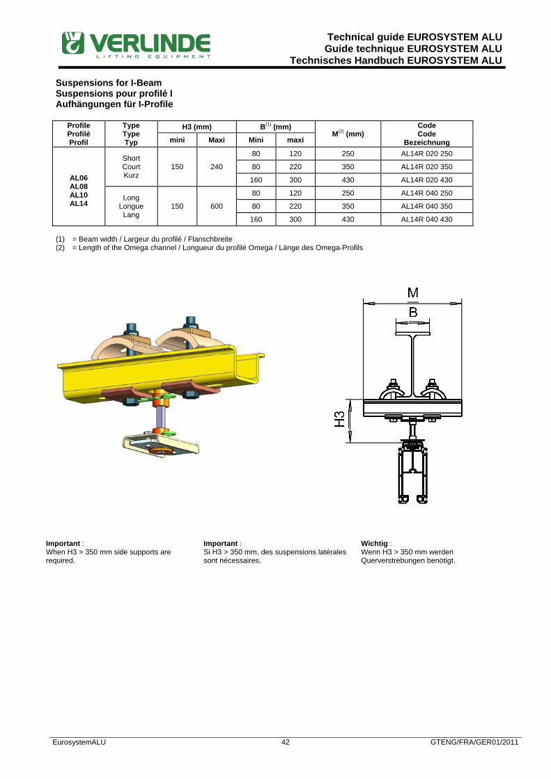
Technical guide EUROSYSTEM ALUGuide technique EUROSYSTEM ALU
Technisches Handbuch EUROSYSTEM ALU
EurosystemALU 42 GTENG/FRA/GER01/2011
Suspensions for I-Beam Suspensions pour profilé I Aufhängungen für I-Profile
Profile Profilé Profil
Type Type Typ
H3 (mm) B(1) (mm) M(2) (mm)
Code Code
Bezeichnung mini Maxi Mini maxi
AL06 AL08 AL10 AL14
Short Court Kurz
150 240
80 120 250 AL14R 020 250
80 220 350 AL14R 020 350
160 300 430 AL14R 020 430
Long Longue
Lang 150 600
80 120 250 AL14R 040 250
80 220 350 AL14R 040 350
160 300 430 AL14R 040 430 (1) = Beam width / Largeur du profilé / Flanschbreite (2) = Length of the Omega channel / Longueur du profilé Omega / Länge des Omega-Profils
Important : When H3 > 350 mm side supports are required.
Important : Si H3 > 350 mm, des suspensions latérales sont nécessaires.
Wichtig : Wenn H3 > 350 mm werden Querverstrebungen benötigt.
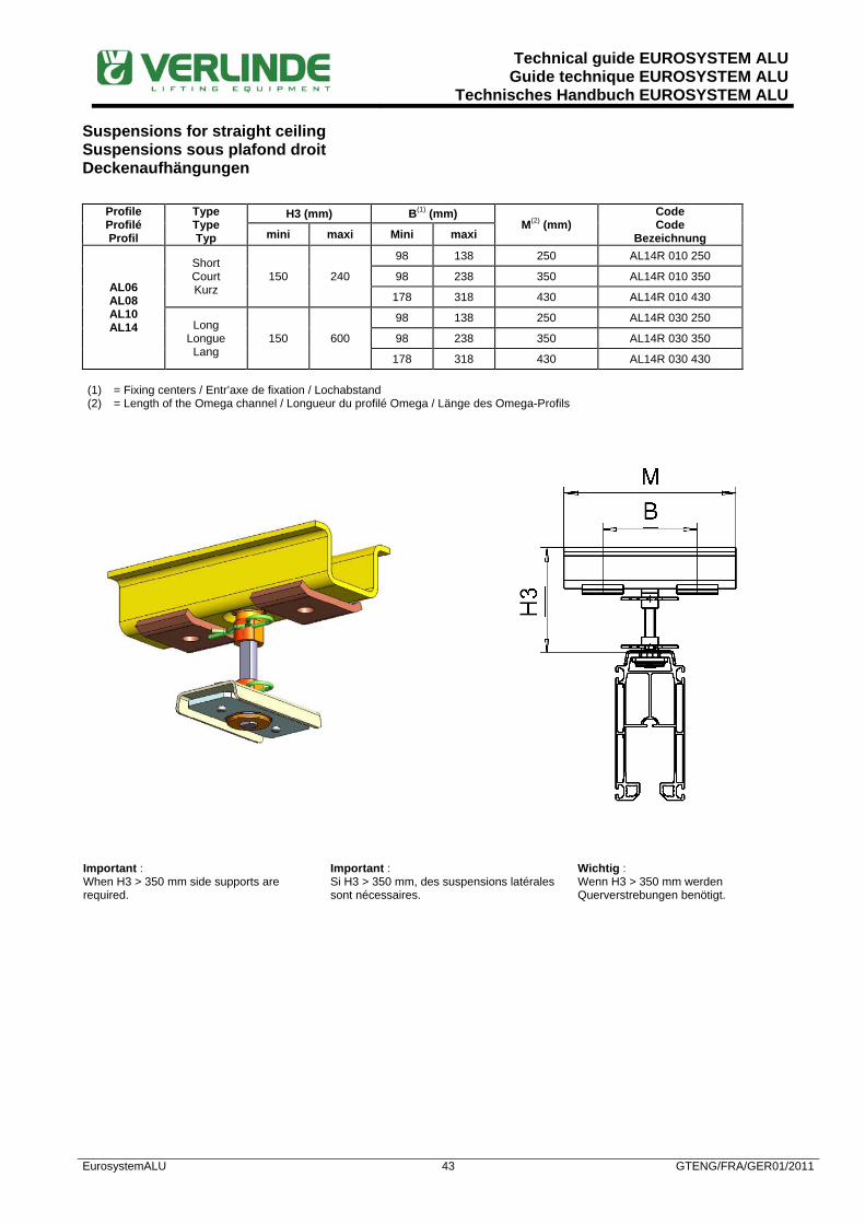
Technical guide EUROSYSTEM ALUGuide technique EUROSYSTEM ALU
Technisches Handbuch EUROSYSTEM ALU
EurosystemALU 43 GTENG/FRA/GER01/2011
Suspensions for straight ceiling Suspensions sous plafond droit Deckenaufhängungen
Profile Profilé Profil
Type Type Typ
H3 (mm) B(1) (mm) M(2) (mm)
Code Code
Bezeichnung mini maxi Mini maxi
AL06 AL08 AL10 AL14
Short Court Kurz
150 240
98 138 250 AL14R 010 250
98 238 350 AL14R 010 350
178 318 430 AL14R 010 430
Long Longue
Lang 150 600
98 138 250 AL14R 030 250
98 238 350 AL14R 030 350
178 318 430 AL14R 030 430 (1) = Fixing centers / Entr’axe de fixation / Lochabstand (2) = Length of the Omega channel / Longueur du profilé Omega / Länge des Omega-Profils
Important : When H3 > 350 mm side supports are required.
Important : Si H3 > 350 mm, des suspensions latérales sont nécessaires.
Wichtig : Wenn H3 > 350 mm werden Querverstrebungen benötigt.

Technical guide EUROSYSTEM ALUGuide technique EUROSYSTEM ALU
Technisches Handbuch EUROSYSTEM ALU
EurosystemALU 44 GTENG/FRA/GER01/2011
Bracket type suspensions Suspensions en applique Seitenaufhängungen
Profile Profilé Profil
Type Type Typ
H3 (mm) B(1) (mm) M(2) (mm)
Code Code
Bezeichnung mini maxi Mini maxi
AL06 AL08 AL10 AL14
Short Court Kurz
150 240
98 138 250 AL14R 010 250
98 238 350 AL14R 010 350
178 318 430 AL14R 010 430
Long Longue
Lang 150 600
98 138 250 AL14R 030 250
98 238 350 AL14R 030 350
178 318 430 AL14R 030 430 (3) = Fixing centers / Entr’axe de fixation / Lochabstand (4) = Length of the Omega channel / Longueur du profilé Omega / Länge des Omega-Profils

Technical guide EUROSYSTEM ALUGuide technique EUROSYSTEM ALU
Technisches Handbuch EUROSYSTEM ALU
EurosystemALU 45 GTENG/FRA/GER01/2011
PUSH TROLLEYS CHARIOTS MANUELS SCHIEBEFAHRWERKE The reduced size of the trolley wheels ensure a smooth and silent running inside the profiles. The nylon wheels are fitted with ball bearings and fixed with circlips. The trolley frame is galvanised.
Par sa faible largeur, la bande de roulement des chariots assure un déplacement souple et silencieux dans les profilés. Les galets nylon sont montés sur roulements à billes et maintenus par circlips. Le corps des chariots est galvanisé.
Die schmalen Räder der Fahrwerke erlauben eine leichte und leise Fahrbewegung der Last. Die Nylonräder sind auf Kugellagern montiert. Die Fahrwerke sind zum besseren Korrosionsschutz galvanisiert.
All trolleys are fitted with integrated guide rollers that ensure a perfect centering in the profiles and enable the running in curves without any particular design.
Tous les chariots sont équipés de roulements guides intégrés assurant un centrage parfait de ceux-ci à l’intérieur des profilés et permettant le passage dans des courbes, sans construction particulière.
Die Fahrwerke für UKA30 und UKA40 sind mit horizontalen Lagern ausgestattet, die eine perfekte horizontale Führung gewährleisten, sowohl in geraden Bahnen als auch in Kurven.
Thanks to the modular construction of the EUROSYSTEM ALU it is possible to fit motor trolleys to a manual installation later on.
La modularité de l’EUROSYSTEM ALU permet de motoriser ultérieurement une installation manuelle existante.
Dank der Modulbauweise können manuelle Fahrwerke nachträglich mit Elektrofahrwerken kombiniert werden.
Single girder hoist trolley Chariot porte-palan monopoutre Einträger Schiebefahrwerk
Profile Profilé Profil
Type Type Typ
SWL Cap.
Traglast (kg)
Code Code
Bezeichnung
AL06 Simple Simple
Einfach 320 AL06T 100

Technical guide EUROSYSTEM ALUGuide technique EUROSYSTEM ALU
Technisches Handbuch EUROSYSTEM ALU
EurosystemALU 46 GTENG/FRA/GER01/2011
Profile Profilé Profil
Type Type Typ
SWL Cap.
Traglast (kg)
Code Code
Bezeichnung
AL08 Simple Simple Einfach
500 AL08T 100

Technical guide EUROSYSTEM ALUGuide technique EUROSYSTEM ALU
Technisches Handbuch EUROSYSTEM ALU
EurosystemALU 47 GTENG/FRA/GER01/2011
Profile Profilé Profil
Type Type Typ
SWL Cap.
Traglast (kg)
Code Code
Bezeichnung
AL10 AL14
Simple Simple
Einfach 1250 AL14T 100
Double Double Doppelt
2000 AL14T 200
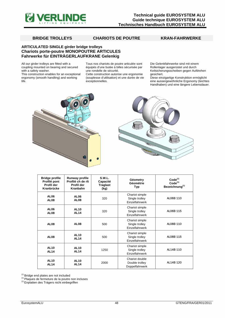
Technical guide EUROSYSTEM ALUGuide technique EUROSYSTEM ALU
Technisches Handbuch EUROSYSTEM ALU
EurosystemALU 48 GTENG/FRA/GER01/2011
BRIDGE TROLLEYS CHARIOTS DE POUTRE KRAN-FAHRWERKE
ARTICULATED SINGLE girder bridge trolleys Chariots porte-poutre MONOPOUTRE ARTICULES Fahrwerke für EINTRÄGERLAUFKRANE Gelenkig All our girder trolleys are fitted with a coupling mounted on bearing and secured with a safety washer. This construction enables for an exceptional ergonomy (smooth handling) and working life.
Tous nos chariots de poutre articulée sont équipés d’une butée à billes sécurisée par une rondelle de sécurité. Cette construction autorise une ergonomie (souplesse d’utilisation) et une durée de vie exceptionnelles.
Die Gelenkfahrwerke sind mit einem Rollenlager ausgerüstet und durch Keilsicherungsscheiben gegen Aufdrehen gesichert. Diese einzigartige Konstruktion ermöglicht eine aussergewöhnliche Ergonomy (leichtes Handhaben) und eine längere Lebensdauer.
Bridge profile Profilé pont
Profil der Kranbrücke
Runway profile Profilé ch de rlt
Profil der Kranbahn
S.W.L. Capacité Traglast
(kg)
Géometry Géométrie
Typ
Code(1) Code(1)
Bezeichnung(1)
AL06 AL08
AL06 AL08 320
Chariot simple Single trolley
Einzelfahrwerk AL06B 110
AL06 AL08
AL10 AL14 320
Chariot simple Single trolley
Einzelfahrwerk AL06B 115
AL08 AL08 500 Chariot simple Single trolley
Einzelfahrwerk AL08B 110
AL08 AL10 AL14 500
Chariot simple Single trolley
Einzelfahrwerk AL08B 115
AL10 AL14
AL10 AL14 1250
Chariot simple Single trolley
Einzelfahrwerk AL14B 110
AL10 AL14
AL10 AL14 2000
Chariot double Double trolley
Doppelfahrwerk AL14B 120
(1) Bridge end plates are not included (1) Plaques de fermeture de la poutre non incluses (1) Enplatten des Trägers nicht einbegriffen

Technical guide EUROSYSTEM ALUGuide technique EUROSYSTEM ALU
Technisches Handbuch EUROSYSTEM ALU
EurosystemALU 49 GTENG/FRA/GER01/2011
LOW HEADROOM SINGLE girder bridge trolleys Chariots porte-poutre MONOPOUTRE ENCASTRES Fahrwerke für EINTRÄGERLAUFKRANE KURZE BAUHÖHE
Bridge profile Profilé pont
Profil der Kranbrücke
Runway profile Profilé ch de rlt
Profil der Kranbahn
S.W.L. Capacité Traglast
(kg)
Geometry Géométrie
Typ
Code Code
Bezeichnung
AL06 AL06 AL08 320
Chariots simples Single trolleys
Einzelfahrwerke AL06B 160
AL06 AL10 AL14 320
Chariots simples Single trolleys
Einzelfahrwerke AL06B 165
AL08 AL08 500 Chariots simples
Single trolleys Einzelfahrwerke
AL08B 160
AL08 AL10 AL14 500
Chariots simples Single trolleys
Einzelfahrwerke AL08B 165
AL10 AL10 AL14 1250
Chariots simples Single trolleys
Einzelfahrwerke AL10B 160
AL14 AL10 AL14 1250
Chariots simples Single trolleys
Einzelfahrwerke AL10B 165

Technical guide EUROSYSTEM ALUGuide technique EUROSYSTEM ALU
Technisches Handbuch EUROSYSTEM ALU
EurosystemALU 50 GTENG/FRA/GER01/2011
AL10 AL10 AL14 2000
Chariots simples Single trolleys
Einzelfahrwerke AL14B 160
AL14 AL10 AL14 2000
Chariots simples Single trolleys
Einzelfahrwerke AL14B 165

Technical guide EUROSYSTEM ALUGuide technique EUROSYSTEM ALU
Technisches Handbuch EUROSYSTEM ALU
EurosystemALU 51 GTENG/FRA/GER01/2011
SINGLE GIRDER RIGID BRIDGE girder bridge trolleys Chariots porte poutre POUTRE MONOPOUTRE RIGIDE Fahrwerke für EINTRÄGER KRAN STARR
Bridge profile Profilé pont
Profil der Kranbrücke
Runway profile Profilé ch de rlt
Profil der Kranbahn
S.W.L. Capacité Traglast
(kg)
Geometry Géométrie
Typ
Code(1) Code(1)
Bezeichnung(1)
AL10 AL14
AL10 AL14 1250
Chariot simple Single trolley
Einzelfahrwerk AL14B 130
AL10 AL14
AL10 AL14 2000
1 Chariot double + 1 Chariot simple 1 Double trolley + 1 Single trolley
1 Doppelfahrwerk + 1 Einzelfahrwerk AL14B 140
(1) Bridge end plates are not included / (1) Plaques de fermeture de la poutre non incluses / (1) Enplatten des Trägers nicht einbegriffen
Rigid Single Girder
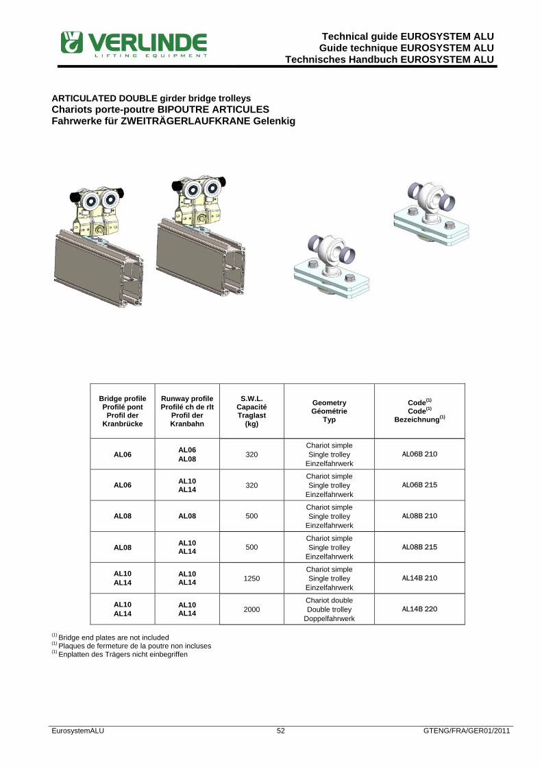
Technical guide EUROSYSTEM ALUGuide technique EUROSYSTEM ALU
Technisches Handbuch EUROSYSTEM ALU
EurosystemALU 52 GTENG/FRA/GER01/2011
ARTICULATED DOUBLE girder bridge trolleys Chariots porte-poutre BIPOUTRE ARTICULES Fahrwerke für ZWEITRÄGERLAUFKRANE Gelenkig
Bridge profile Profilé pont
Profil der Kranbrücke
Runway profile Profilé ch de rlt
Profil der Kranbahn
S.W.L. Capacité Traglast
(kg)
Geometry Géométrie
Typ
Code(1) Code(1)
Bezeichnung(1)
AL06 AL06 AL08 320
Chariot simple Single trolley
Einzelfahrwerk AL06B 210
AL06 AL10 AL14 320
Chariot simple Single trolley
Einzelfahrwerk AL06B 215
AL08 AL08 500 Chariot simple Single trolley
Einzelfahrwerk AL08B 210
AL08 AL10 AL14 500
Chariot simple Single trolley
Einzelfahrwerk AL08B 215
AL10 AL14
AL10 AL14 1250
Chariot simple Single trolley
Einzelfahrwerk AL14B 210
AL10 AL14
AL10 AL14 2000
Chariot double Double trolley
Doppelfahrwerk AL14B 220
(1) Bridge end plates are not included (1) Plaques de fermeture de la poutre non incluses (1) Enplatten des Trägers nicht einbegriffen
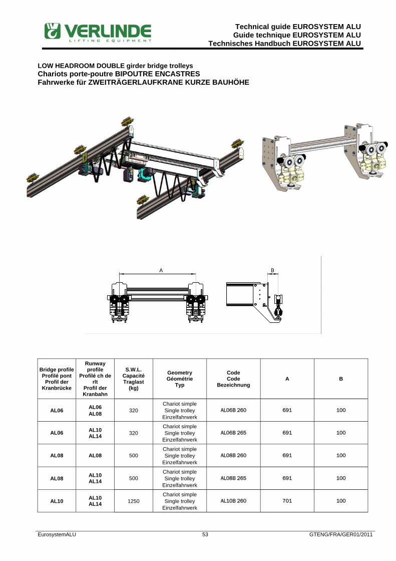
Technical guide EUROSYSTEM ALUGuide technique EUROSYSTEM ALU
Technisches Handbuch EUROSYSTEM ALU
EurosystemALU 53 GTENG/FRA/GER01/2011
LOW HEADROOM DOUBLE girder bridge trolleys Chariots porte-poutre BIPOUTRE ENCASTRES Fahrwerke für ZWEITRÄGERLAUFKRANE KURZE BAUHÖHE
Bridge profile Profilé pont
Profil der Kranbrücke
Runway profile
Profilé ch de rlt
Profil der Kranbahn
S.W.L. Capacité Traglast
(kg)
Geometry Géométrie
Typ
Code Code
Bezeichnung A B
AL06 AL06 AL08 320
Chariot simple Single trolley
Einzelfahrwerk AL06B 260 691 100
AL06 AL10 AL14 320
Chariot simple Single trolley
Einzelfahrwerk AL06B 265 691 100
AL08 AL08 500 Chariot simple Single trolley
Einzelfahrwerk AL08B 260 691 100
AL08 AL10 AL14 500
Chariot simple Single trolley
Einzelfahrwerk AL08B 265 691 100
AL10 AL10 AL14 1250
Chariot simple Single trolley
Einzelfahrwerk AL10B 260 701 100

Technical guide EUROSYSTEM ALUGuide technique EUROSYSTEM ALU
Technisches Handbuch EUROSYSTEM ALU
EurosystemALU 54 GTENG/FRA/GER01/2011
AL14 AL10 AL14 1250
Chariot simple Single trolley
Einzelfahrwerk AL10B 270 716 100
AL10 AL10 AL14 2000
Chariots simples Single trolleys
Einzelfahrwerke AL14B 260 701 100
AL14 AL10 AL14 2000
Chariots simples Single trolleys
Einzelfahrwerke AL14B 270 716 100

Technical guide EUROSYSTEM ALUGuide technique EUROSYSTEM ALU
Technisches Handbuch EUROSYSTEM ALU
EurosystemALU 55 GTENG/FRA/GER01/2011
DOUBLE GIRDER RIGID BRIDGE girder bridge trolleys Chariots porte poutre POUTRE BIPOUTRE RIGIDE Fahrwerke für ZWEITRÄGER KRAN STARR
Bridge profile Profilé pont
Profil der Kranbrücke
Runway profile Profilé ch de rlt
Profil der Kranbahn
S.W.L. Capacité Traglast
(kg)
Geometry Géométrie
Typ
Code(1) Code(1)
Bezeichnung(1)
AL10 AL14
AL10 AL14 1250
Chariot simple Single trolley
Einzelfahrwerk AL14B 230
AL10 AL14
AL10 AL14 2000
Chariots doubles Double trolleys
Doppelfahrwerke AL14B 240
(1) Bridge end plates are not included / (1) Plaques de fermeture de la poutre non incluses / (1) Enplatten des Trägers nicht einbegriffen
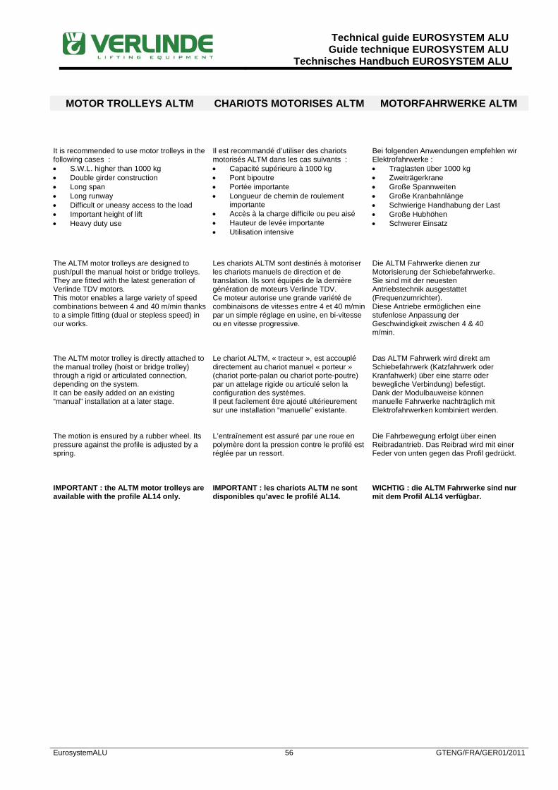
Technical guide EUROSYSTEM ALUGuide technique EUROSYSTEM ALU
Technisches Handbuch EUROSYSTEM ALU
EurosystemALU 56 GTENG/FRA/GER01/2011
MOTOR TROLLEYS ALTM CHARIOTS MOTORISES ALTM MOTORFAHRWERKE ALTM It is recommended to use motor trolleys in the following cases : • S.W.L. higher than 1000 kg • Double girder construction • Long span • Long runway • Difficult or uneasy access to the load • Important height of lift • Heavy duty use
Il est recommandé d’utiliser des chariots motorisés ALTM dans les cas suivants : • Capacité supérieure à 1000 kg • Pont bipoutre • Portée importante • Longueur de chemin de roulement
importante • Accès à la charge difficile ou peu aisé • Hauteur de levée importante • Utilisation intensive
Bei folgenden Anwendungen empfehlen wir Elektrofahrwerke : • Traglasten über 1000 kg • Zweiträgerkrane • Große Spannweiten • Große Kranbahnlänge • Schwierige Handhabung der Last • Große Hubhöhen • Schwerer Einsatz
The ALTM motor trolleys are designed to push/pull the manual hoist or bridge trolleys. They are fitted with the latest generation of Verlinde TDV motors. This motor enables a large variety of speed combinations between 4 and 40 m/min thanks to a simple fitting (dual or stepless speed) in our works.
Les chariots ALTM sont destinés à motoriser les chariots manuels de direction et de translation. Ils sont équipés de la dernière génération de moteurs Verlinde TDV. Ce moteur autorise une grande variété de combinaisons de vitesses entre 4 et 40 m/min par un simple réglage en usine, en bi-vitesse ou en vitesse progressive.
Die ALTM Fahrwerke dienen zur Motorisierung der Schiebefahrwerke. Sie sind mit der neuesten Antriebstechnik ausgestattet (Frequenzumrichter). Diese Antriebe ermöglichen eine stufenlose Anpassung der Geschwindigkeit zwischen 4 & 40 m/min.
The ALTM motor trolley is directly attached to the manual trolley (hoist or bridge trolley) through a rigid or articulated connection, depending on the system. It can be easily added on an existing “manual” installation at a later stage.
Le chariot ALTM, « tracteur », est accouplé directement au chariot manuel « porteur » (chariot porte-palan ou chariot porte-poutre) par un attelage rigide ou articulé selon la configuration des systèmes. Il peut facilement être ajouté ultérieurement sur une installation “manuelle” existante.
Das ALTM Fahrwerk wird direkt am Schiebefahrwerk (Katzfahrwerk oder Kranfahwerk) über eine starre oder bewegliche Verbindung) befestigt. Dank der Modulbauweise können manuelle Fahrwerke nachträglich mit Elektrofahrwerken kombiniert werden.
The motion is ensured by a rubber wheel. Its pressure against the profile is adjusted by a spring.
L’entraînement est assuré par une roue en polymère dont la pression contre le profilé est réglée par un ressort.
Die Fahrbewegung erfolgt über einen Reibradantrieb. Das Reibrad wird mit einer Feder von unten gegen das Profil gedrückt.
IMPORTANT : the ALTM motor trolleys are available with the profile AL14 only.
IMPORTANT : les chariots ALTM ne sont disponibles qu’avec le profilé AL14.
WICHTIG : die ALTM Fahrwerke sind nur mit dem Profil AL14 verfügbar.

Technical guide EUROSYSTEM ALUGuide technique EUROSYSTEM ALU
Technisches Handbuch EUROSYSTEM ALU
EurosystemALU 57 GTENG/FRA/GER01/2011
Motor trolleys for straight tracks (profiles AL10 & AL14) Chariots motorisés pour profilés droits (profilés AL10 & AL14) Motorfahrwerke für gerade Bahnen (Profile AL10 & AL14)

Technical guide EUROSYSTEM ALUGuide technique EUROSYSTEM ALU
Technisches Handbuch EUROSYSTEM ALU
EurosystemALU 58 GTENG/FRA/GER01/2011
Technical data for TMU motor Données techniques du moteur TMU Technische Daten des TMU Motors
The TMU units are driven with fixed voltages and frequencies. The technical data are therefore the same for all line voltages.
Les moteurs TMU utilisent des tensions et des fréquences fixes. Les données techniques sont donc identiques pour toutes les plages d’alimentation.
Die TMU besitzen nur einen Betriebspannung- und Frequenzbereich. Aus diesem Grund die technischen Angaben für alle Spannungsbereiche gültig.
The scope of standard power supply covers voltages from 380 V to 480 V under frequency 50 or 60 Hz. In case of power voltages outside of the range (mini 230 V, maxi 600 V), transformers are supplied.
La plage des alimentations standard couvre toutes les tensions de 380 V à 480 V, fréquence 50 ou 60 Hz. En dehors de cette plage de tensions (minimum 230 V, maximum 600 V), des transformateurs sont fournis.
Der Standardbetriebsspannung reicht von 380V bis 480V bei 50Hz oder 60Hz. Ausserhalb dieser Standardbetriebsspannung (230 bis 600V) wird ein Transformator vorgeschaltet.
Motor code / Code moteur / Motorbezeichnung MF06MK200
Duty factor / Facteur de marche / Einschaltdauer S3-40%
Speed control / Type de contrôle / Mode Inverter / Variateur /
Inverter supply voltage / Alimentation variateur / Stromeinspeisung des Inverters V 380-480 440-480
Motor voltage / Alimentation moteur / Stromeinspeisung des Motors V 400 460
Frequency / Fréquence / Frequenz Hz 100 120
Synchronous speed / Vitesse de synchronisation / Synchrongeschw. RPM 3000 3600
Nominal speed / Vitesse nominale / Nenngeschw. RPM 2855 3430
Brake torque / Couple de feinage / Bremsmoment Nm 2 2
Starting torque / Couple de démarrage / Anlaufmoment Nm 3.0 2.9
Starting current / Intensité de démarrage / Anlaufmoment A 4.2 4.3
Maximum torque / Couple maxi / Höchstmoment Nm 3.0 2.9
Speed at max. torque / Vitesse au couple maxi / Geschw. bei Höchstmoment RPM 0 0
80% of max. torque / 80 % du couple maxi / 80 % des Höchstmoments Nm 2.4 2.4
Speed at 80% torque / Vitesse à 80 % du couple maxi / Geschw. bei 80 % des Höchstmoments RPM 2200 2600
Current at 80% torque / Intensité à 80 % du couple maxi / Strom bei 80 % des Höchstmoments A 2.1 2.1
Starting power factor / Facteur de démarrage / Anlauffaktor 0.72 0.70
Weight / Poids / Gewicht kg 10 10
No-load current / Intensité sans charge / Strom ohne Last A 1.0 1.0
Stator resistance at 20 °C / Résistance des enroulements à 20° C / Wicklungwiderstand bei 20° C Ω 34 34
Nominal power / Puissance nominale / Nennleistung kW 0.3 0.37
Nominal current / Intensité nominale / Nennstrom A 1.2 1.2
Power factor / Facteur puissance / Leistungsfaktor 0.57 0.59
Efficiency / Efficience / Wirkungsgrad 0.65 0.65

Technical guide EUROSYSTEM ALUGuide technique EUROSYSTEM ALU
Technisches Handbuch EUROSYSTEM ALU
EurosystemALU 59 GTENG/FRA/GER01/2011
Electrical kit for motor trolleys Kit électrique pour chariots motorisés Elektrischer Kit für Motorfahrwerke The ALTM motor trolleys are supplied with an electrical kit which does not require any particular wiring. The installation is made very easy with « plug & play » connections between the flat cables, motors and cubicles. Each end has a number to simplify the assembly on site, without diagram.
Les chariots motorisés ALTM sont livrés avec un kit électrique qui ne nécessite aucun câblage spécifique. Le montage est rendu très simple grâce aux liaisons « plug & play » entre les câbles plats, les moteurs et les coffrets. Chaque extrémité est repérée pour permettre un assemblage rapide, sans schéma.
Die ALTM Fahrantriebe werden komplett einem vormontierten elektrischen Kit geliefert, es ensteht kein Verdrahtungs-aufwand. Die Installation ist durch die vorgefertigten und verdrahtenn Stecker sehr einfach. Alle Stecker sind eindeutig mit Aufklebern gekennzeichnet und können einfach, ohne Schaltplan, zugeordnet werden.
The ALTM motors are fed thru the hoist cubicle which is delivered adapted to the motions (cross and/or long travel). No extra contactors are needed.
Les moteurs ALTM sont alimentés par le palan, dont le coffret est livré adapté aux mouvements (direction et/ou translation). Il n’y a pas besoin de contacteurs supplémentaires.
Die ALTM Fahrantriebe werden durch das Hubwerk mit Spannung versorgt. Es werden keine gesonderten Schütze benötigt.
Other solutions than flat cable are available to shorten the hook approach dimensions (busbar parallel, conductors inside the profiles…). PLEASE CONSULT US.
Il est possible de diminuer les côtes d’approche avec d’autres types d’alimentation que le câble plat (gaine parallèle, conducteurs intégrés …) NOUS CONSULTER.
Andere Lösungen anstatt Flachkabel sind verfügbar, um die Anfahrmaße zu verringern (Schleifleitung parallel oder im Profil integriert…). AUF ANFRAGE.
ELECTRICAL KIT « A » (Hoist & cross travel)
KIT ELECTRIQUE « A » (Levage & direction)
ELEKTRISCHER KIT « A » (Heben & Katzfahren)
TMU cross travel motor Moteur de direction TMU
TMU Katzfahrmotor
X23
X24
X22
Control pendant hoist + cross travel Commande levage + direction Steuertaster Heben + Katzfahren
Main switch (option) Sectionneur (option) Trennschalter (Option)
Flat cable main power feeding line (option) LAG câble plat (option) Flachkabelstromzuführung (Option)
Chain hoist Palan à chaîne E-Kettenzug

Technical guide EUROSYSTEM ALUGuide technique EUROSYSTEM ALU
Technisches Handbuch EUROSYSTEM ALU
EurosystemALU 60 GTENG/FRA/GER01/2011
ELECTRICAL KIT « B »
(Hoist & long travel) KIT ELECTRIQUE « B » (Levage & translation)
ELEKTRISCHER KIT « B » (Heben & Kranfahren)
ELECTRICAL KIT « C » (Hoist, cross & long travel)
KIT ELECTRIQUE « C » (Levage, direction & translation)
ELEKTRISCHER KIT « C » (Heben, Katz- & Kranfahren)
TMU cross travel motor Moteur de direction TMU
TMU Katzfahrmotor
X26X25
X27
X28
X21 X23X24
X22
Main switch (option) Sectionneur (option) Trennschalter (Option)
Chain hoist Palan à chaîne E-Kettenzug
Flat cable main power feeding line (option) LAG câble plat (option) Stromzuführung (Option)
Control pendant hoist + cross + long travel Commande levage + direction + translation Steuertaster Heben + Katz- + Kranfahren
TMU long travel motors Moteurs de translation TMU
TMU Kranfahrmotore
Flat cable main power feeding line (option) LAG câble plat (option) Stromzuführung (Option)
X26
X25
X27
X28
X23
X24
X22
Main switch (option) Sectionneur (option) Trennschalter (Option)
Chain hoist Palan à chaîne E-Kettenzug
Control pendant hoist + long travel Commande levage + translation Steuertaster Heben + Kranfahren
TMU long travel motors Moteurs de translation TMU
TMU Kranfahrmotore