fuse demonstrator document fuse project ae: 25 816 user friendly line protection relay ... ·...
TRANSCRIPT

FUSE Demonstrator document Ver. 1.3b Page 1
FUSE Demonstrator Document
FUSE PROJECTAE: 25 816
User friendly Line protection Relayusing FPGA
First User: Jacobsen Electro

FUSE Demonstrator document Ver. 1.3b Page 2
PART I
TitleUser friendly Line protection Relay using FPGASimpler interface and a 10:1 mechanical size reduction achieved by new technology
AE number and associated TTNAE 25816 associated to TTN DELTA
AbstractJacobsen Elektro AS is a manufacturer of HV (high voltage) and control equipment for the Power Industry.The company was established in 1891 and has been producing electrical equipment since 1913. JacobsenElektro decided to introduce new technology in order to improve the performance and appearance of a keyproduct range: power system protection and control equipment. The company delivers to power utilities,power-consuming industries and offshore oil installations in Europe, Africa and Asia. The annual turnoverof the company is 13 MEuro.
The primary rationale for the Application experiment was to update outdated products, as availability ofcomponents became problematic. Secondly, a reduction in production cost was necessary to compete in themarket. Introduction of a user friendly setting method was anticipated to improve market shares. Thirdly,performance of the product was mandatory, due to new standards of EMI.
Outdated analogue products were to be replaced by modern digital solutions thus resulting in extremelyuser-friendly products, improved EMC performance, improved flexibility and high standardisation in theproduction process. The main technologies introduced were DSP and FPGA in addition to high resolutionA/D and high-speed A/D conversion followed by digital filtering. The knowledge transfer has been verysuccessful, and the obtained experience will certainly help to improve the quality and appeal of severalplanned future products.
Lesson learnt on dealing with subcontractors has given the first user a different and more operative view ofsuch actions. During a previous project the need for competent and reliable subcontractors turned out to becritical. The lack of proper technological knowledge at the first user made the choice of subcontractorsextremely difficult. This experience has had a major negative factor in estimating the duration ofsubcontracted tasks; thus a very conservative scheduling has been applied. However, this current projectturned out with very positive lesson learnt. On this basis a recently initiated project is therefore reorganised,and attention particularly focused on the selection and supervision of subcontractors.
The physical size of the new Jacobsen Elektro product is reduced by a factor of 10.
Jacobsen Elektro learnt by means of this AE to deal with VHDL design and how to organise design projectsin this field.
The AE project cost was 70.7 KEuro and lasted 7 months. The total investment for the new product hasbeen 125 KEuro.
The Payback period is estimated to 16 months and the ROI of the FUSE investment is 925%.
Keywords and signatureThe keywords for this AE is power system protection, power lines, power distribution, high voltage, FPGA,Data Acquisition, user friendly interface, subcontractor selection, reduction of mechanics.The signature for this AE is 3-03605550221-2-2971-2-29-N
1. Company name and addressCompany: Jacobsen Elektro asOffices: Prestaker Industriområde, Hokksund, NORWAYMail: Jacobsen Elektro as, P.O. Box 52, N-3301 Hokksund, NORWAYCommunication: Phone +47 3225 1800 Fax +47 3225 1801 Email: [email protected] manager: Tor GrinnaLogo:

FUSE Demonstrator document Ver. 1.3b Page 3
2. Company sizeThe present number of employees is 85 from which 20 are involved in R&D, 30 in manufacturing, 10 inadministration, 10 in marketing and 15 in engineering.
In different phases of the project more than fifteen of these were directly involved- on a full-time base: 1 project manager and technical expert
1 analogue and digital electronics expert2 protection experts (application engineer / user)1 programmer
- on a part-time base: 2 constructors / designers4 protection experts (application engineer / user)1 prototype builder1 analogue electronics design engineer1 project reference group consisting of 5 employees
The annual turnover of the company is 13 MEuro.
3. Company business descriptionJacobsen Elektro was established in 1892 as the second electrotechnical company ever established inNorway. It is located in Hokksund, 60 km outside Oslo, and manufactures products and delivers servicesfor power system transmission, power distribution, heavy industry and offshore power supply systems.Product development and product maintenance is located within the company, with some participation fromoutside expert consultants and specialised manufacturers. Products developed and manufactured within thecompany are:
• Turnkey deliveries for power transmission and power distribution systems• Power system protection and control systems (hardware and software)• Consultancy and services on power system protection application, maintenance and planning• High-voltage disconnectors (11-420kV)• High voltage switch gear (11-33kV)• Energy metering systems
4. Company markets and competitive position at the start of the AEJacobsen Elektro is presently involved in Northern Europe especially Norway, Sweden, Finland and theUK. Also some regions of the former Soviet Union like Estonia, Latvia, Lithuania and Bosnia are presentmarkets. Outside Europe the number of customers is rapidly increasing including the Far East, CentralAmerica, South America and sub-Sahara countries in Africa.The power industry forms a worldwide market for most products of the type manufactured by JacobsenElektro. Protective relays which are one of our key products are manufactured by a relatively small numberof international companies, and are without major changes sold all over the world. The annual turnover ofthe company is 13 mill. Euro of which 50% is related to the protective relays. The estimated total marketfor protective relays is:
• Norway 5 mill Euro per year – market share 75%• Scandinavia 18 mill Euro per year – market share 10%• Globally 750 mill Euro per year – market share 3%
The total number of product types produced is approximately 20. The markets that Jacobsen Elektro isoperating in is:
• Europe• Africa• Latin America• Middle-East and Far East
The products that Jacobsen Elektro offers are:• Turnkey HV-Substations• Power system protection and control system• Consultancy and services on protection and maintenance• High-voltage disconnectors
FUSE Demonstrator document Ver. 1.3b Page 4
• High-voltage switch gear• Energy metering systems.
The largest local competitors are ABB, Siemens and GEC-Alsthrom. Japanese and American companiesare also heavily involved in the market. The ability to survive in the competition from these largeorganisations lies in several factors. Jacobsen Elektro is focused on niche products and services especiallyadapted to customer needs. A major advantage is the large number of application engineers within thecompany. Specification, development, testing and approval of new equipment is mainly based on the user'srequirement. This is extremely useful when competing with large organisations where new products aredeveloped in isolated departments with limited or no user contact. The small and flexible organisation ofJacobsen Elektro also enables the company to act fast to changes in the market or to respond quickly tocustomer needs. These principles have proved successful and the turnover has therefore steadily increasedthrough the past five years. However, the present product range of analogue protective relays was clearlyoutdated, and had to be replaced by modern systems. Properties like communication, programmablefunctions, user-friendliness and flexibility are all difficult or impossible to obtain with traditional analoguetechnology.The market demands solutions based on most recent technology. To improve the competitive strength of theJacobsen Elektro products it is of great importance to minimise the structure of equipment settings. Settingof existing product required several days of work while the new product requires only a maximum of 30parameter settings. Furthermore such an improvement increases product flexibility and reduces cost ofproduction.The added user friendly interface opens market will initiate a demand for updating of older installation, thusan increase in demands of new equipment in the Scandinavian will take place.
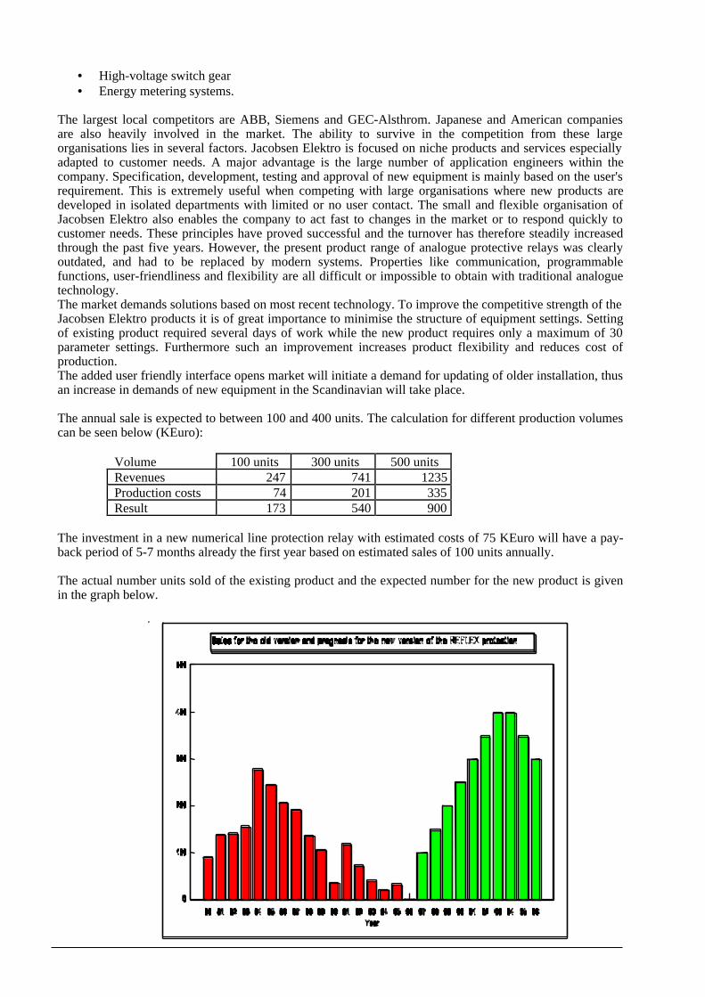
The annual sale is expected to between 100 and 400 units. The calculation for different production volumescan be seen below (KEuro):
Volume 100 units 300 units 500 unitsRevenues 247 741 1235Production costs 74 201 335Result 173 540 900
The investment in a new numerical line protection relay with estimated costs of 75 KEuro will have a pay-back period of 5-7 months already the first year based on estimated sales of 100 units annually.
The actual number units sold of the existing product and the expected number for the new product is givenin the graph below.
FUSE Demonstrator document Ver. 1.3b Page 5
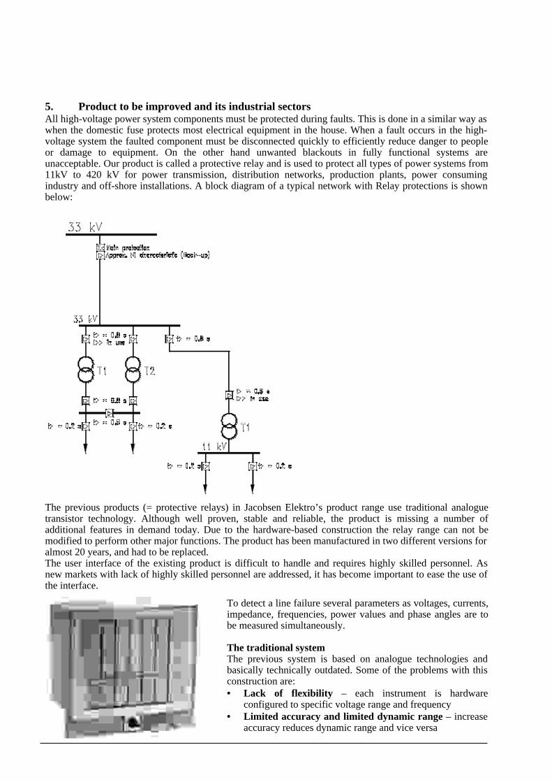
5. Product to be improved and its industrial sectorsAll high-voltage power system components must be protected during faults. This is done in a similar way aswhen the domestic fuse protects most electrical equipment in the house. When a fault occurs in the high-voltage system the faulted component must be disconnected quickly to efficiently reduce danger to peopleor damage to equipment. On the other hand unwanted blackouts in fully functional systems areunacceptable. Our product is called a protective relay and is used to protect all types of power systems from11kV to 420 kV for power transmission, distribution networks, production plants, power consumingindustry and off-shore installations. A block diagram of a typical network with Relay protections is shownbelow:
The previous products (= protective relays) in Jacobsen Elektro’s product range use traditional analoguetransistor technology. Although well proven, stable and reliable, the product is missing a number ofadditional features in demand today. Due to the hardware-based construction the relay range can not bemodified to perform other major functions. The product has been manufactured in two different versions foralmost 20 years, and had to be replaced.The user interface of the existing product is difficult to handle and requires highly skilled personnel. Asnew markets with lack of highly skilled personnel are addressed, it has become important to ease the use ofthe interface.
To detect a line failure several parameters as voltages, currents,impedance, frequencies, power values and phase angles are tobe measured simultaneously.
The traditional systemThe previous system is based on analogue technologies andbasically technically outdated. Some of the problems with thisconstruction are:• Lack of flexibility – each instrument is hardware
configured to specific voltage range and frequency• Limited accuracy and limited dynamic range – increase
accuracy reduces dynamic range and vice versa

FUSE Demonstrator document Ver. 1.3b Page 6
• Metering and curve-recording impossible – no recording or registration of data are possible as itwould interfere with the measurements
• Communication impossible – born without communication as no data is available• Large size – many components (approximately 300) are spread on several PCBs due to both size of
components and heating distribution• Low consumer appeal – difficult to operate• Difficult to find necessary components - outdated analogue components and outdated mechanical
parts like connectors.
The measuring system has to detect an error within _-1_ power cycle (typical 10-30mS) to avoidunnecessary damages to the power line system, which is to be protected.
Measuring Module
High speed24 bitsRAM
Signalconditioning
DSP
Sampling inputs : 7*2 channels each max 17.280 sampl/s
Pre-filtering and curve correction
Filter output :
Apparent systemsampling rate 7channels each at
max 1.440 sampl/s
2 X 14bitsA/D+ ref
SignalConditioning
SignalConditioning
Overvoltageprotection
Overvoltageprotection
Overvoltageprotection
GalvanicIsolation
Overvoltageprotection
Overvoltageprotection
Overvoltageprotection
Overvoltageprotection
SignalConditioning
SignalConditioning
SignalConditioning
SignalConditioning
SignalConditioning
GalvanicIsolation
GalvanicIsolation
GalvanicIsolation
GalvanicIsolation
GalvanicIsolation
GalvanicIsolation
Amplifiers. Calibrated to 1* and 16* attenuation for expanded measuring range
To Processing Module
2 X 14bitsA/D+ ref
2 X 14bitsA/D+ ref
2 X 14bitsA/D+ ref
2 X 14bitsA/D+ ref
2 X 14bitsA/D+ ref
2 X 14bitsA/D+ ref
Block diagram of the measuring module
6. Description of the technical product improvementsA protective relay detects critical or destructive power system conditions by continuously measuring andfiltering a number of values. Typical derived measuring values are voltage, current impedance, frequency,power value, phase angle. Following the measurement and filtering logic co-ordinates the outputs of thedifferent measuring circuits. Finally the trip/block decision is available within 5-30 ms. Because aprotective relay is an important safety device the demand for safety and reliability is very high. Trends andpre-fault recordings should also be available as well as local and remote regulation and control.

FUSE Demonstrator document Ver. 1.3b Page 7
The new unit is freely programmable stand-alone modules containing all necessary hardware and softwareto operate completely on its own, or to be inserted into a larger system as one of more modules of the samekind. The response from the measuring system and related logic appears on output contacts or through adisturbance-free Optical Fibre Local Area Network (LAN). The new technology also allows for a reductionin physical size in the range of 1:10 compared to the traditional solutions.
System architecture and specificationsThe architecture of the system was restricted by the size of the cabinet and the need for easy access to allrear interfaces and the power supply. To enable easy hardware-updating and maximum flexibility thesystem was subdivided into a front-panel module (interconnection board), a processing module, ameasuring module and an I/O module. The modules are described in more detail at the following pages.Two different DSPs are applied as already known experiences of the company in this matter has beenapplied. The TMS320C30 (floating point) are applied to calculate the final result while the M56002 (fixedpoint) is applied in the measuring module to achieve fast conversion of measurements.
The measuring moduleThe following demands apply:• Fast and accurate synchronisation of the sampling to power system frequency (16,66Hz, 25Hz, 50Hz
and 60Hz)• Extremely high disturbance-immunity during major power surges close to the unit• Seven input channels for analogue measurements• High accuracy throughout a very wide measuring range. Each measuring channel contains two separate
14bit A/D converters in parallel with two different calibrations• All 2*7 input must be read at the same time and converted to digital values (synchronous sampling).• High-speed operation using a pre-filtering sampling rate of max 17280 samplings/sec per channel• Fast and accurate pre-filtering integrated in the measuring system• High-speed apparent system sampling rate = 1440 samplings/sec in each channel• Automatic curve-correction to compensate for non-linearity in the input circuit
These demands posed a need for an extremely accurate and adjustable timer and control unit in addition tomassive processing power to handle all data collected within one sampling. To accurately control thesampling system an FPGA unit located on the processor board is applied. It controls the synchronisation,the sampling system and the main system real-time function with an accuracy of 1 ms undisturbed by DSP-load or any other variables. The DSP on the measuring board pre-filters seven channels at a rate of max2*7*17280 measurements per second and stores and organises each apparent sampling value (7*1440values per sec) for immediate transmission to the processor board.
The main processor systemThe following demands apply:• Main memory handling including bootstrap and other start-up functions• Signal conditioning and other relay functions (final filtering and measurement, relay logic, menu
handling, operational readouts etc)• Inter-module communication when using more modules to build a complete system• LAN communication• Keyboard• Display• I/O handling (except the binary high-voltage I/O which is located at the power I/O module)• Watchdog function

FUSE Demonstrator document Ver. 1.3b Page 8
32 bits highspeed RAM
Supervisoryfunction
FPGA, Master timer and secondary timer,Sampling and synchronization, Interface toFlash, UARTS (comm), I/O and main DSP
Main DSP
Relay functions Measurements
Relay logic
I/O handling and External
Communication
User interface Menu handling
Memory handling and OS functions
16 bitsFLASHmemory
Display
Keyboard
Real Time Clock
3 ch. high speedoptical fiber
comm
1 ch. RS232Interface
E2PROM
DigitalI/O
4 channelcommunication
unit
To Measuring Module
Processing Module
Block diagram of the main module
The I/O module and the front module have no advanced digital functions and operate only as a support-module for the main system board.
External system specifications:• 4 current measuring inputs. Rated input values 1 or 5 A• 3 voltage measuring inputs. Rated input value 110 V• 8 binary inputs. Operational value 24-220 V bipolar DC• Power supply 24-220V bipolar DC• 8 relay outputs (external watchdog function included)• 4*16 character LCD display• 3 front-panel LED’s for system status• 4*4 keyboard• 1 front-panel RS-232 port• 1 duplex IEC-870 optical fibre connection for internal system expansion bus• 2 duplex IEC-870 optical fibre connections for LAN connection (duplex ring bus)
Internal specifications:• 7 (4+3) input transformers for signal conditioning and galvanic isolation. Output levels +-2.5V• Input filter and signal conditioning• 7 input channels each containing two14 bit A/D converters for enhanced accuracy in low measuring
ranges.• Primary sampling rate per channel max 18000 samples/sec• Apparent sampling rate per channel after pre-filtering max 1500 samples/sec• FPGA for independent and accurate tuning and control of the sampling process• Local high-speed ram at the measuring board for temporary storage of measured values• 60 MHz DSP at measuring board handling pre-filtering and curve-correction in all channels at
maximum sampling speed. Also used to control the local bus and communication towards the mainCPU.
• 60 MHz DSP at processor board handling remaining functions including the relay measurement andrelay logic based on the apparent samplings, external communication and user-interface
• FPGA for independent and accurate timing control for all external timer functions. This function isdemanding and critical and can hardly be performed satisfactorily by any of the DSPs.
• 4 Mbit flash memory for permanent data and program storage• 4Mbit RAM (expandable to 16 Mbit)• 3 duplex optical fibre connections each 5Mbit/sec for system expansion bus and LAN• Control circuits for front panel RS-232, system expansion bus and the duplicated LAN communication

FUSE Demonstrator document Ver. 1.3b Page 9
FPGA ComplexityThe design implemnted in the FPGA consists of the following functions:• Master Timer• Secondary timer• Syncronisation of system• Sampling controller• Interface to FLASH memory• Communication - UARTs• Data distribution to and from main DSP• 29 kGates utilises inFPGA
Main product improvements are:• Better overall system stability and availability, Self supervision for vital parts of the system.• Reduced number of hardware variants from 20 to 2.– more efficient and less costly production• Reduced number of spare parts and availability hereof improved• Internal modularity enables partial system upgrading in the future• Faster and more efficient development of new applications based on existing hardware• Greatly improved flexibility and ability to adapt to particular customer demands• Higher measuring accuracy, wider measuring ranges and improved measuring stability• Curve recording and playback for pre-fault analysis• Communication between units, and in control systems/LAN’s• Improved Man-Machine-Interface• Reduce the number of spare part modules from approximately 100 to 5.
7. Choices and rationale for the selected technologies, tools and methodologiesA wide range of products are developed, maintained and manufactured by Jacobsen Elektro. Thecompany’s previous knowledge in electronics was concentrated on traditional analogue measuring systemsand analogue technologies. The competence of Jacobsen Elektro had to be upgraded in digital technologiesespecially the use of DSP’s and FPGA’s and related technologies. In the future an upgrade to customdesign/VLSI is also foreseen.
TechnologyThe following alternatives were considered as the major technologies for the relay modules:
• Analogue components (traditional analogue technology)• Non-programmable digital technology• Software-programmable technology / DSP• FPGA design• VLSI / Custom design
The criteria for the selection of technology were based on product being configurable and production costreduction. Furthermore, the final product and thus the selected technology was to be user friendly andprogrammable at end user site. FPGA design was selected with the rationale described below.
The traditional analogue solution was immediately rejected because the device should be programmable.Non-programmable digital technology was also quickly given up, mainly due to lack of flexibility andmissing possibilities to obtain acceptable user-friendliness. The company therefore had to use technologiespreviously unknown to it.
VLSI/custom design seemed to be attractive, but the production volume was recently estimated to 300-500units per year. The initial cost and expected payback-time was not favourable. It was also indicated thatsome of the more advanced functions like memories, 14 bit A/D converters and processing capacity wouldbe missing within such a solution. VLSI/custom design was rejected – probably for later revaluation.

FUSE Demonstrator document Ver. 1.3b Page 10
The DSP/software programmable solution was attractive because of its flexibility. It also enabled directcommunication to remote dispatch centres (power operation and control centres) which today is in veryhigh demand in the power industry. However, tests and simulations showed that some functions wereunsafe and unstable compared with the demands of the customers – even when using a 60 MHz DSP. Thiswas particularly the case for the external timing functions, the sampling synchronisation and a number ofinternal timers and control functions. It was therefore decided that a number of critical functions should beperformed in a FPGA controlled system.In the very wide range of expertise and technologies Jacobsen Elektro must master the design andapplication of FPGA and DSP based solutions. In turn this enables the company to move on to moreadvanced systems based on for instance VLSI/custom design. When appropriate some tasks demandingparticular expertise or special equipment should be carried out by subcontractors, to allow for an efficientcross-fertilisation between power protection experts and electronics design engineers working both withinand outside the company.
Traditional analogue solution (RXR) New FGPA/DSP solution (RefleX)
ToolsViewlogic was selected as FPGA design tools using VHDL. The rationale for this choice was cost ofsoftware, PC based and easy access to training. The choice of VHDL rather than schematics was consideredas a suitable step for the company in terms of required effort in relation to prepare technical staff for higherintegration in future projects and products.
MethodologiesA following design flow was applied• Specification of product• Feasibility study of functions to be included in the FPGA. Including determination of interface
to DSP and memory• Overall specification of the FPGA - Functional and interfacing• Specification functional block diagram levels for the FPGA. Description of interactions
between these blocks.• Design work VHDL coding - per function• Simulation - per function• Integration of functions• Simulation of FPGA• Prototyping• Test Bench evaluation
FUSE Demonstrator document Ver. 1.3b Page 11
As a learning process was associated with this design we applied a whirl pool developmentprocess; thus gaining benefit from the lesson learnt already into the new product rather than into afuture product.
Furthermore, several tests are required to certify this type of product. The range tests are• Electrical insulation tests (High-voltage tests) carried out in existing test facilities• Disturbance and immunity tests (EMC compliance etc) standard test at subcontractor• Climatic tests (Heat, cold, moisture, condensation, dust) carried out at in existing test facilities• Mechanical tests (Fall, bump, vibration, seismic) carried out at subcontractor• Thermal tests on inputs and outputs (overload) carried out at existing test bench• Storage and shipment tests (Extreme climatic and mechanical tests) carried out at
subcontractor
8. Expertise and experience in microelectronics of the company and the staff allocated tothe project
The main area of expertise in Jacobsen Elektro is in the manufacturing and use of heavy-duty high-voltageequipment. However important products are based on electronics and other low-voltage equipment, andduring the last sixty years Jacobsen Elektro has developed and manufactured a number of complex andadvanced measuring systems for power line protection and control. Analogue electronics has been appliedto the old product as well as approximately 200 TTLs for the digital functions. It has been the tradition ofJacobsen Elektro to produce every part (for a period even screws) for its products. In Jacobsen Elektro thefollowing experience were available to the project:
• Traditional analogue electronics development (40 man-years)• Traditional digital electronics development (25 man-years)• Algorithm design for power system protection functions (50 man-years)• Software development (10 man-years)• Mechanical construction (50 man-years)• Project administration and organisation (30 man-years)• Protection application experts (16 experts, 120 man-years)• Power system protection design, manufacturing, testing and maintenance (300 man-years)
The first user has no experience with CAD tools.
9. Workplan and rationaleA workplan was set up to manage the project. Specific tasks were grouped and assigned to responsiblepersonnel as follows. Jacobsen Elektro conducted the technical management. Training (FPGA) wasperformed by CONTEC design. Specification of the product was conducted by Jacobsen Elektro andsupported by Contec Design. Jacobsen Elektro conducted R&D with support from the subcontractor ofConstruction. Test and Evaluation was performed by Jacobsen Elektro.
RationaleAs the capability of Jacobsen prior to the AE didn't include FPGA design these capability had to be addedto the project either as a technology transfer to Jacobsen or to be performed at subcontractor. Furthermore ithas been concluded that a technology step to FPGA was feasible for Jacobsen, thus the design part wasdecided to take place at first user. The overall split of tasks was defined as design is to be performed atJacobsen, while manufacture of PCB was to be subcontracted. In the rationale for the subcontractor it wasfeasible to have as few subcontractors as possible.
Risk AnalysisA risk analysis was conducted to focus on potential risk elements. The analysis was focussed onsubcontractor performance, as previously experience has been less successful.
It was considered as important to have alternative suppliers of FPGA. This consideration was based onJacobsen being uncertain on interfacing to FPGA technologies.

FUSE Demonstrator document Ver. 1.3b Page 12
Pricing of FPGA devices is vital for the price of the final product. Furthermore distributor predicted adecline in price.
Contingency plan1. During the feasibility study each potential FPGA supplier was to be evaluated as alternative supplier.2. Pricing was to be followed closely to enable change of FPGA type.
Workplan
The forecasted workplan has been maintained within few days.
Task description
Technical ManagementProject management including follow up on each task.• Work done
Schedule follow up,Cost follow-upConducting project meetingsContact to subcontractorPresentation of results for the board of managers
• Who did whatTor Grinna performed these tasks as project manager except for the cost follow-up, which wasperformed by the financial manager.
• ResponsibilitiesJacobsen had the overall general responsibility of the project
Task Name Duration Start Finish
Technical Management 172d 03.11.97 30.06.98
Training 152d 01.12.97 30.06.98
Application needs 88d 01.12.97 01.04.98
Accuracy and functional logic 64d 02.04.98 30.06.98
Specification 16d 03.11.97 24.11.97
Measuring module 16d 03.11.97 24.11.97
Processing module 16d 03.11.97 24.11.97
System specification 16d 03.11.97 24.11.97
Internal specification 16d 03.11.97 24.11.97
Delivery of Specification 1d 24.11.97 24.11.97
R & D 28d 03.11.97 10.12.97
Choices of technologies 10d 03.11.97 15.11.97
Wide range A/D conversion 4d 16.11.97 20.11.97
Filter techniques 3d 21.11.97 25.11.97
EMC 11d 26.11.97 10.12.97
Construction 65d 11.12.97 11.03.98
Hardware construction 65d 11.12.97 11.03.98
Software construction 65d 11.12.97 11.03.98
End of Construction 1d 11.03.98 11.03.98
Test/ Evaluation 69d 12.03.98 16.06.98
Hardware test/evaluation 69d 12.03.98 16.06.98
Software test/evaluation 69d 12.03.98 16.06.98
End of Test / Evaluation 1d 16.06.98 16.06.98
Dissemination Results 85d 02.03.98 26.06.98
End of Dissemination of Results 1d 26.06.98 26.06.98
24.11
11.03
1
Nov Dec Jan Feb Mar Apr May Juntr 4, 1997 Qtr 1, 1998 Qtr 2, 1998
FUSE Demonstrator document Ver. 1.3b Page 13
• Knowledge transferKnowledge on management of FPGA design specific in dealing with subcontracting oftraining, design and testing was transferred to the company
Workpackage TrainingTraining FPGA technology, Verilog design work, Accuracy• Work done
Training FPGA technologyTraining Verilog design toolsAccuracy and functional block
• Who did whatJacobsen and the subcontractors performed these tasks.Jacobsen participated as trainee.Contec participated as provider of training of FPGA technology and Verilog design toolsJetro participated as provider of training of measuring methodologies
• ResponsibilitiesJacobsen had the responsibility of this WP
• Knowledge transferKnowledge on required input to the subcontractor and how to interpret reports form thesubcontractor was transferred to the company.
Workpackage SpecificationTechnical specification of functionality and performance of the new FPGA and testingrequirement• Work done
Analysis of requirement,Analysis of feasibility including estimate of final costs and size of chipBlock diagram level specificationSpecification of blocksFPGA design trainingContract with the subcontractor
• Who did whatThe project team at Jacobsen performed these tasks. The subcontractor did support in terms offeasibility and requirement for the FPGA in relation the processing module.
• ResponsibilitiesThe project manager had the responsibility of this WP
• Knowledge transferKnowledge on capability of the specific FPGA technology was transferred to the company.Furthermore, knowledge on subcontracting was transferred.
Workpackage R&DChoice of technology, A/D conversion, Filter techniques, EMC consideration• Work done
Choice of technologyA/D conversion and supplemental DSP technologyFilter techniquesEMC consideration

FUSE Demonstrator document Ver. 1.3b Page 14
• Who did whatContec performed these tasks in close co-operation with the technical staff at Jacobsen.Jacobsen supported the subcontractor in aspects of EMC consideration.
• ResponsibilitiesContec had the responsibility of this WP.
• Knowledge transferKnowledge on methodologies and design techniques were transferred to the company.
Workpackage ConstructionConstruction of hardware, construction of software and manufacture of prototype• Work done
Construction of hardwareconstruction of softwareManufacture of prototypes
• Who did whatThe technical staff at Jacobsen performed these tasks. PCB manufacture and FPGAimplementation were submitted to subcontractor.
• ResponsibilitiesJacobsen had the responsibility of this WP
• Knowledge transferExperience on FPGA design work was transferred to the company. Furthermore, knowledge onsubcontracting the FPGA implementation was transferred.
Workpackage Test and EvaluationSoftware test and evaluation, Hardware test and evaluation• Work done
Software test and evaluationHardware test and evaluationApart from the tests of the project the following were performed:• Electrical insulation tests (High-voltage tests)• EMC compliance• Climatic tests (Heat, cold, moisture, condensation, dust)• Mechanical tests (Fall, bump, vibration, seismic)• Thermal stress tests on inputs and outputs• Storage and shipment tests (Extreme climatic and mechanical tests)
• Who did whatThe project team at Jacobsen and the subcontractors performed this task Product performanceand evaluation of results were performed by Jacobsen. Tests in bold were carried out bysubcontractor.
• ResponsibilitiesJacobsen had the responsibility of this WP.
• Knowledge transferKnowledge on testing prototype FPGA solution was transferred to the company.
Scheduled efforts versus actual efforts.
Workpackage TaskCost
First User effort Subcontractors cost
KEuro Planned Actual Planned Actual

FUSE Demonstrator document Ver. 1.3b Page 15
Persondays
Person days KEuro KEuro
Management 7.1 30 26Specifications 10.5 22 24Design 36.9 16 18 32 33.7Prototyping 15.4 50 44 5 4.2Evaluation & Test 0.8 5 4TOTAL 70.7 123 116 37 37.9
10. Subcontractor informationJacobsen Electro has skilled knowledge on the HV technology, but had lack on some technologies relatedmicroelectronics, hence subcontractors with expertise in microelectronics were needed to achieve therequired skills.
Subcontractors were selected for their particular expertise in matter of:• DSP and FPGA technologies• FPGA application and programming• Kernel design for DSP• Real-time software application for DSP• PC-based Graphic User-interface for system configuration• Analogue and digital measuring technology, A/D conversion• Digital filter technologies and signal conditioning• Analogue filter technologies• Disturbance control during conducted or radiated disturbances (EMC)• Environmental protection design to withstand climatic, mechanical and electrical stresses• Algorithm design for power system protection functions
We were looking for a suited company and found the Norwegian Company Contec Design. Contec Designis specialised in consulting services within electronics and is a spin-off from NERA (former ABB Nera)who is world market leader within satellite communication. Contec Design's main product area isdevelopment and design within electronics, software, mechatronics and test/measurement. Contec Designhas been used also in this project for design assistance.
Contec Design developed and constructed the measuring module in co-operation with Jacobsen Elektro.Their responsibility was to ensure that the quality and accuracy was according to specification.
A contract was signed for each subcontractor. The contracts relate to subcontracted work, IPR, non-disclosure agreement (NDA), contact personnel and prices. IPR of the designed work is descried asproperty of the first user, hence design and production material are handed over to first user. A NDA wasstating non-disclosure to any third party without a preceding agreement with the first user was signed.Prices of the work to be performed and payment terms was settled.
Name: Contec Design ASAddress: Bergerveien 12, N-1361 Billingstad, NORWAYPhone: +47 6724 3200Fax: +47 6724 4720Contact person: Rune SandbergEmail: [email protected]: +47 6724 3973Company size: 50 employeesCompany business: Consultancy services within digital and analogue electronics, software,
mechatronics and test/measurement. EMC experts.Companies’ markets: Norway, primarily industrial companies within electronics and information
technology.Expertise/experience: Development and design within electronics, software, mechatronics and
test/measurement.
FUSE Demonstrator document Ver. 1.3b Page 16
Personnel involved: Rune Sandberg, Department Manager and M.Sc. managed the work inelectric engineering. He is supported mainly by Geir Olav Gyland andAgnar Grødal, both M.Sc. in electric engineering and Bjørn H. Medhus,Cand. Scient from the University of Oslo. A number of other persons fromContec Design are involved on demand.
Name: Jetro A/SAddress: N-4950 Risør, NORWAYPhone +47 3714 9400Fax: +47 3714 9401Email: [email protected] person: Knut ØsterholtCompany size: 5 employees, all engineers.Company business: Development of hardware for electronics, analogue and digital systems.
Development of software for embedded systems and PC applications.Companies’ markets: Jetro’s customers are typically companies with no internal development
department or companies where the development department needsassistance in their projects. Most of customers are located in Norway.
Expertise/experience: High competence after more than 20 years of experience in programming,hardware design and implementation. This involves specialist competencein numeric and analogue hardware and know-how about numericmeasuring technology, numerical signal treatment, the use of DSP,different memory types, microprocessors, A/D conversion and analoguemeasuring technology.
PART II
11. Barriers perceived by the company in the first use of the AE technology
Managerial barriersBeing a very traditional managed company since 1892, with a major in change in 1933, it has been verydifficult to convince management to change the production methodology or new products, etc. However thefinancial results in the 1980’s lead to a change of management in 1993.
Technology barriersThe engineering staff employees were highly motivated to introduce and apply new technology. Thetechnological barriers were the product requirements versus achievable performance of the new technology.
Resource barriersThe major barrier perceived was the access to external experts capable of managing the new technology.External experts often have a limited application area to deal with i.e. in terms of disciplines of measuringanalogue values. These experts need to acquire knowledge of HV technology. HV application requiresenhanced methodologies applied in the analogue circuitry, especially in matters of accuracy and dynamicrange. The DSP and FPGA experts including software programmers were almost unable to perceive theparticular needs of the application. A major training effort was necessary to inform the programmers andtechnology experts of the practical application of the end product.
A similar project was initiated in 1997, but was a total fiasco, due to lack of communication between theinvolved partners of that project. Thus the anticipated project schedule was set with too large time frames.Also as the experience from that project was difficulties in communication with subcontractors a too longtime frame was set to this task.
12. Steps taken to overcome the barriers and arrive at an improved product
Managerial barriersThe managerial barriers of the traditional managed company were overcomed by presentation andeconomical potential to the management. Expressed commitment from the project team also convinced themanagement.
Technology barriers

FUSE Demonstrator document Ver. 1.3b Page 17
The major steps taken in order to overcome these barriers were training and improved information. It wasforeseen that Jacobsen Elektro should learn from the experts to increase the technological level of thecompany, and this knowledge transfer worked very well. The need for extensive training of the hiredexperts in protection application subjects was not expected but turned out to be crucial for the success of theproject. In order to overcome the barrier related to choosing the best suited technology for JacobsenElektro's products a consultation was carried out in co-operation with the chosen subcontractor ContecDesign to evaluate the existing electronics and estimate the advantages that might be gained by usingmodern electronics.
Resource barriersWith support from the TTN external experts capable of managing the new technology were contacted.Experts with application area of analogue measuring methodology and conversion of analogue data intodigital data were engaged. Through intensive introduction and information on HV technology these expertsbecame aware of the particular needs of the HV application.
The TTN supported the first user in selection of suitable subcontractors to overcome the technologicalbarriers.
13. Knowledge and experience acquiredThe experience transferred was extensive in a wide range of digital technologies. Even though sometechnologies were previously applied additional knowledge was still transferred. New areas of knowledgetransferred to Jacobsen Elektro:
• DSP hardware, application, specification and programming• FPGA hardware, application, specification and programming• Digital filter techniques• Memory technologies, application, specification and programming• Communication technologies in combination with the above mentioned components• Updated knowledge of analogue components (improved and changes components)
Knowledge was transferred to the subcontractors as introduction to specific HV technologies such as highdemands to measuring accuracy and noise immunity.
Jacobsen Elektro has during this project acquired 2 DSP development kits and one FPGA development kit.
Jacobsen has compared to the planned knowledge transfer gained more knowledge in terms of interactionbetween the digital measuring techniques of HV. It was presumed by Jacobsen, that the analogue measuringcircuitry was to be unchanged, but actually DSP can reduce the number of measuring circuit as some valuescan be calculated instead of being actual measured.
14. Lessons learnedThe project was basically more demanding than expected from the beginning, mainly as our subcontractorshad to be introduced to the HV technology during the project.It may be concluded that developing products based on functional demands from application experts (users)– assisted by technology experts brings good results. The opposite approach where the technology expertsare in charge of development with application experts as assistants is unsuitable in our situation. The factthat the project team of Jacobsen Elektro was dominated by application experts – not by technology experts– was the most important single success-factor in the process of developing a commercial, user-friendly andstrongly improved product.
Still in a major project many experts have to be involved. In this project more than twenty-five differentexperts were involved. This calls for active co-ordination, as well as extremely good contact between thedifferent professionals to enable efficient transfer of knowledge. An extensive project specification createdin advance is vital to enable all these people to interact in an efficient manner.
On the managerial side good project descriptions and proper project management appeared to be muchmore important than initially expected.

FUSE Demonstrator document Ver. 1.3b Page 18
The use of inexperienced and inefficient subcontractors proved to be disastrous, but this problem wasdifficult to spot early in the project. Later on better qualified and initially more expensive subcontractorswere crucial for the success of the project.A lesson learned in subcontracting has been to be more careful in verifying claimed skills of subcontractors.In the future Jacobsen Elektro will rather go for the skilled rather than the cheapest subcontractor. In thisproject one subcontractor, Jetro was selected on basis of previously experiences while Contec Design wasselected as being a new subcontractor.
PART III
15. Resulting product, its industrialisation and internal replicationIn addition to the technology transfer in electronics the project also includes a number of other importanttasks in mechanics, production planning, sales. These tasks have enabled the company to almostimmediately turn the project into an industrialised product. The technological improvements transferred toJacobsen Elektro will ease development of future products and increase market share. Particularly in thefield of protective relays, industrial control and local control a number of new products have been identifiedfor future development.
A very useful experience was to learn how to introduce unknown and unfamiliar technology into thecompany. Because the company was missing basic capabilities in a number of technological fields it turnedout to be extremely difficult to identify competent and reliable subcontractors. At a certain time thisproblem came very close to ruining the project. This experience has directly affected our future projectorganisation in recently initiated projects.
The skills achieved during this project will be applied in future projects. Firstly, the skills have to be widelyknown within the company to create a progressive development environment in the company. Secondly,evolution of future products requires improvements in use of DSP and FPGA. The replication in terms ofDSP will lead to improvements in software algorithm. FPGAs will be applied to minimise and customisethe products.
The future internal replication is to use the same technology in other products. Such as part of a localcontrol system for substations, part of a measuring system, distance to fault measuring and part of a cablefault location system.
Twenty-five units of the prototype has been produced and installed at end user sites near Jacobsen. Thepurpose of these field installations is to gain experience of actual performance. The results from theseinstallations were to be used to improve the final product. By the end of 1998 these installations showed noneed for changing the product, hence the prototype has been upgrading to production type. Productionseries was initiated in January 1999. The cost of the industrialisation of the product itself (product changesbased on the field experiment) is estimated to 4 KEuro. Total cost of industrialisation comprisesfurthermore 50 KEuro for testing and certification to comply with CE-marking. These costs are high, due tothe high safety and reliability requirement tests are required to certify this type of product. The extend oftests is• Electrical insulation tests (High-voltage tests)• Disturbance and immunity tests (EMC compliance etc)• Climatic tests (Heat, cold, moisture, condensation, dust)• Mechanical tests (Fall, bump, vibration, seismic)• Thermal tests on inputs and outputs (overload)• Storage and shipment tests (Extreme climatic and mechanical tests)The product is today successfully introduced on the market. A total of 60 units has been ordered for the firsthalf year of 1999 versus the planned 150 units for the whole year of 1999.
16. Economic impact and improvement in competitive position

FUSE Demonstrator document Ver. 1.3b Page 19
The project has strongly improved Jacobsen Elektro’s competitive abilities, mainly based on improvedadaptation to customer needs and production cost reductions for manufacturer and user: The newtechnology also allows solutions which today seem to be a must in the business. Without these possibilitiesthe company would not be able to deliver equipment at all. The total cost of product improvement has been125 KEuro. The additional costs are partly related to the need of additional knowledge of digital filteringtechniques, EMC testing and additional knowledge of DSP techniques. Added value to customer is:
• Cost-efficient manufacturing, storage and distribution• The ability to deliver custom design• Greatly improved user-friendliness• Reduced need for customer training and support• Improved customer satisfaction when using new technology• Communication capabilities• The new technologies introduced in the company enables it to improve other products and to
develop more advanced products in the future.
The Return of Investment of this project is very short as the cost improvement per instrument is 1100 Eurocorresponding to a 15% reduction compared to the old product. This reduction is not only related to lesselectronics applied, but also to the fact that the mechanical parts are reduced by a factor of 10 in size andprice.
The Payback period is estimated to 16 months. Estimating a product lifetime of four years with acontinuous profit rate will lead to a ROI on the FUSE investment of:
ROI (FUSE investment) = 666/72*100% = 925%
Total expected SalesEstimate per july 1999
0
50
100
150
200
250
300
350
400
1995 1996 1997 1998 1999 2000 2001 2002
Num
ber
of R
elay
s
New Product
Old product
Old Product only
The Added value to the end user is mainly the friendly user interface, easy and logical setting. Theequipment has become much smaller and easier to install. It is even possible for some skilled end user toperform installation of the equipment. Maintenance will become easier, as repair often will be related tochangeable module, which can be shipped for repair elsewhere.
17. Summary of best practice and target audienceBest practice can be summarised to perform proper project management and engaged competentsubcontractor.We have found the best practice in terms of management to have a formal work plan - a point of reference- for participants of the project including the subcontractor. The plan is to be followed up by projectmeeting and reporting to management, when a milestone is achieved.
We have found it important to verify claimed skills of subcontractors. It was essential to engage andintroduce the subcontractor - the actual persons on the task(s) - to personnel and the cultural tradition ofyour company. Subcontractors will be needed in for task for which your our company don't have theknowledge, capability or resources to perform. But remember subcontracting requires subcontractormanagement by your own company.

FUSE Demonstrator document Ver. 1.3b Page 20
The target audience for dissemination may be found in small and medium sized companies involved inindustrial measurement and control. Also in companies developing intelligent machinery includingmeasuring and feedback systems may benefit from these experiences. Based on the particular challenges inthe project, and the solutions found the following characteristic target audience may be suggested:
• Measuring with high accuracy through a wide measuring range (high voltage applications)• Measuring in environments with high disturbance levels• Critical timing and need for accurate synchronisation• Digital measuring technologies and digital filtering• Modular construction of complex measuring systems