fuse demonstrator document fuse application · pdf fileredesign of the neurosign® 100...
TRANSCRIPT

FUSE Demonstrator Document
FUSE Application Experiment Number 2174

Redesign of the Neurosign® 100 using Microprocessor Technology
Abstract
The Magstim Company Limited is a small company specialising in the design and manufacture ofelectro-medical instruments. These products are marketed in the niche medical area of humannervous system stimulation and monitoring. The Company’s product include a range of MagneticNerve Stimulators and a Nerve Monitoring System; the Neurosign® 100.
This product utilises discrete analogue components to amplify the very small nervous systemelectrical signals detected via needle electrodes placed in muscles to provide audible and visibleindications for clinicians and surgeons.
The objective of the application experiment is to apply microprocessor technology to provideadditional functional enhancements, including:
• Detailed waveform storage and display features.• Expansion to 8 channels.• Time measurement functions using software generated cursor facilities.• Analogue signal conditioning functions including mute features.• Data storage, comparison and archiving.
These additional product features will provide the improved Neurosign® 100 product with a majorcompetitive advantage in a higher value market segment. The enhanced product competitivenesswill generate additional sales of 41 units in the first year, with an increase in sales revenue of over100%. This increase will be achieved because of the higher price of the improved product.
The total cost of the prototype development was 71.85 KECU, and the prototype developmentrequired 11.5 months to complete from the start date of October 1996. This development costproduced a payback period of 15 months and produced a return on investment (ROI) of 82.% inyear 1 and 205% in year 2.
The microprocessor development programme resulted in the Magstim Company developing aformalised software design and review management process that enabled the developmentprogramme to be completed on schedule and to budget. This development approach has beenadopted by the company as a best practice project management approach for subsequentreplication projects.
The experience of introducing microprocessor technology into the highly regulated area of medicalelectronics will be of interest to other organisations operating in safety critical industrial sectors, suchas transport products, mining and quarrying, as well as companies involved in the manufacture ofmedical, precision and optical instruments

1. Company name and address
The Magstim Company Limited,Spring Gardens Industrial Estate,Whitland,Carmarthenshire,SA34 0HR,United Kingdom.
2. Company size
The Magstim Company has an annual sales turnover of 3 MECU per annum, and currentlyemploys 34 people, 6 of whom are involved in product development. The productdevelopment team consists of 2 electronic engineers, 1 electronic technician, 1 mechanicalengineer, 1 mechanical technician, and one draughtsman. The remaining employees are involvedin sales and marketing (5), production (20), and general administration and managementfunctions (3).
3. Company business description
The Magstim Company designs, manufactures and markets a range of electro-medicalinstruments and accessories that allow clinicians to assess various parts of the human nervoussystem. Specifically, these products are the Magstim® models: 200, 250, Quadropulse andRapid, which are all types of Magnetic Nerve Stimulator, and the Neurosign® 100, which is atwo channel Nerve Monitoring system. The latter product is the subject of this applicationexperiment.
The company sells its products worldwide, through a network of distributors. Exports,principally to the rest of Europe, the USA, Japan and the Far East, account for some 85% ofthe company’s turnover.
The company undertakes all of its product designs internally; this included mechanical andelectronic design.
The company procures the basic components for its equipment, including screen printed casesand bare circuit boards, and manufactures the product range in-house from these basiccomponents. The company also undertakes all final product testing.
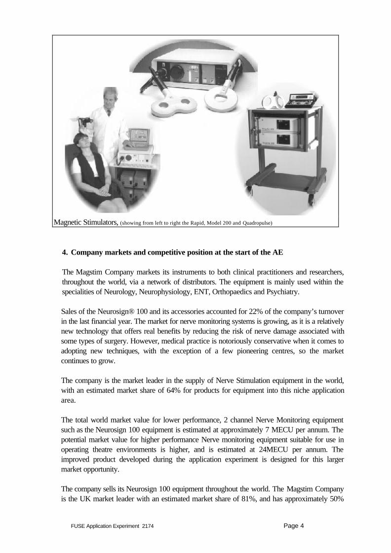
Figure 1, below, shows some of the company’s range of Magnetic Stimulators.
FUSE Application Experiment 2174 Page 4
4. Company markets and competitive position at the start of the AE
The Magstim Company markets its instruments to both clinical practitioners and researchers,throughout the world, via a network of distributors. The equipment is mainly used within thespecialities of Neurology, Neurophysiology, ENT, Orthopaedics and Psychiatry.
Sales of the Neurosign® 100 and its accessories accounted for 22% of the company’s turnoverin the last financial year. The market for nerve monitoring systems is growing, as it is a relativelynew technology that offers real benefits by reducing the risk of nerve damage associated withsome types of surgery. However, medical practice is notoriously conservative when it comes toadopting new techniques, with the exception of a few pioneering centres, so the marketcontinues to grow.
The company is the market leader in the supply of Nerve Stimulation equipment in the world,with an estimated market share of 64% for products for equipment into this niche applicationarea.
The total world market value for lower performance, 2 channel Nerve Monitoring equipmentsuch as the Neurosign 100 equipment is estimated at approximately 7 MECU per annum. Thepotential market value for higher performance Nerve monitoring equipment suitable for use inoperating theatre environments is higher, and is estimated at 24MECU per annum. Theimproved product developed during the application experiment is designed for this largermarket opportunity.
The company sells its Neurosign 100 equipment throughout the world. The Magstim Companyis the UK market leader with an estimated market share of 81%, and has approximately 50%
Magnetic Stimulators, (showing from left to right the Rapid, Model 200 and Quadropulse)

FUSE Application Experiment 2174 Page 5
of the European market for such nerve monitoring equipment. The company’s market share osspecific market areas is detailed below:
Germany 80%The Benulux area 46%Rest of Europe 22%North America 16%Japan 6%
The present two channel monitor market is an extremely competitive one. At the high end of thecompetition is NIM 2 manufactured and marketed by Xomed Inc. of Florida. The NIM 2 is themonitor that has led the US market for the last 5 years. Whilst not being superior inperformance to the Neurosign®100 it was installed at every teaching hospital prior toNeurosign's launch into the USA market. This equipment has a very limited waveform displayand it is this which creates a strong competitive argument for its use (even though it is nearly$7,000 more expensive than Neurosign® 100).
At the low end, the Brackmann 2 by WR Electronics of Minnesota offers a battery operatedmonitor for around $ 5,000. This product suffers from performance limitations and has hadlittle market penetration due to its low level of sophistication.
Axxon Biomedical , New York has a four channel monitor, but is hampered by its extreme highcost ($32,000) and low level of user friendliness. At present, some surgeons who wish to carryout multichannel monitoring (both motor and somata-sensory) will use a high endEMG/Evoked potential unit e.g. Nicolet Viking. This type of machine is designed for use in theNeurophysiology laboratory, not the operating theatre. It does not give an audible indication ofnerve activation to the surgeon and at around $ 60,000, it is seen as the wrong product for thejob at hand.
The company that develops and efficient, cost effective, user friendly multichannel product willbe the company that becomes the market leader in the intra-operative nerve monitoring field.As a result of the application experiment, The Magstim company expects to be able tointroduce a “tailor made” product for this market, which will establish it as that leader.

FUSE Application Experiment 2174 Page 6
5. Product to be improved and its industrial sector
Industry sector: Medical Instrumentation (Prodcom code 331)
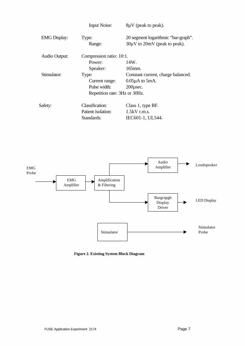
The product to be modified by the inclusion of an embedded microprocessor is theNeurosign® 100 Nerve Monitor. It is designed to monitor nerves in the human body,especially those in motor neural pathways which are at risk of damage during surgicalprocedures. This is important as the consequence of such damage is the paralysis of theassociated muscles. Typical examples of procedures where the monitor is used are spinalsurgery or the removal of a tumour which has grown around a nerve. Any “mechanical” activitynear the nerve at risk will tend to stimulate it, causing the muscles innervated by that nerve tocontract. The instrument recognises this contraction by detecting the resulting, small electricalsignal (the Electromyogram or EMG), via needle electrodes placed in the muscle and gives anaudible and visible indication of the level of activity. It can detect the EMG well below thethreshold of visible muscle movement. In addition to detecting responses due to inadvertentmechanical stimuli, the monitor may be used to confirm if a structure is a nerve by directlystimulating it with a small electrical current applied via a stimulation probe. The Neurosign®100 Nerve Monitor is shown in Figure 2.
The product uses an instrumentation amplifier to interface to the EMG probes, and severaloperational amplifier circuits to process this signal up to the point at which it is converted to thebargraph display format. This conversion is performed using a discrete LM3915 device. All ofthe functions of the device are performed using discrete analogue and digital components.
A brief specification of the instrument, which utilises analogue circuits only, is as follows:
EMG Amplifier No. of Channels: 2.Bandwidth: 10Hz - 10kHz ±3dB.CMRR: 100dB.
Neurosign® 100 Nerve Monitor
FUSE Application Experiment 2174 Page 7
Input Noise: 8µV (peak to peak).
EMG Display: Type: 20 segment logarithmic “bar-graph”.Range: 30µV to 20mV (peak to peak).
Audio Output: Compression ratio: 10:1.Power: 14W.Speaker: 165mm.
Stimulator: Type: Constant current, charge balanced.Current range: 0.05µA to 5mA.Pulse width: 200µsec.Repetition rate: 3Hz or 30Hz.
Safety: Classification: Class 1, type BF.Patient isolation: 1.5kV r.m.s.Standards: IEC601-1, UL544.
EMGAmplifier
Amplification& Filtering
AudioAmplifier
BargrapghDisplayDriver
Stimulator
Loudspeaker
LED Display
StimulatorProbe
EMGProbe
Figure 2. Existing System Block Diagram
FUSE Application Experiment 2174 Page 8
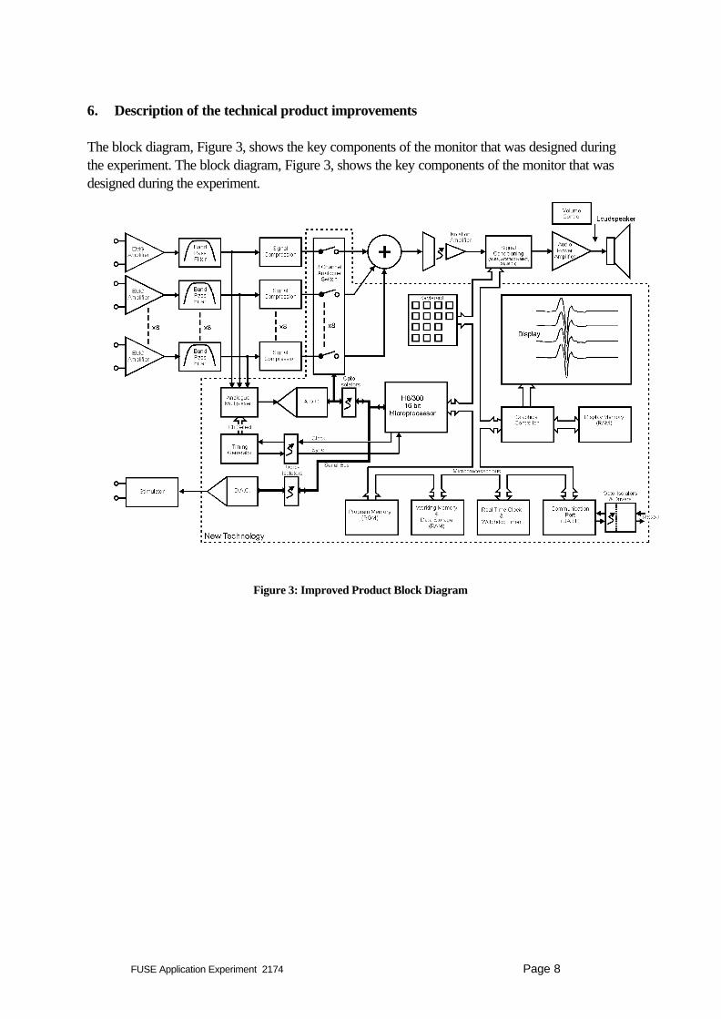
6. Description of the technical product improvements
The block diagram, Figure 3, shows the key components of the monitor that was designed duringthe experiment. The block diagram, Figure 3, shows the key components of the monitor that wasdesigned during the experiment.
Figure 3: Improved Product Block Diagram

FUSE Application Experiment 2174 Page 9
The EMG signal path from patient input to the audio output remains essentially the same as it isin the Neurosign® 100, except that 8, rather than 2, channels have been implemented and ananalogue switch has been included in each signal part, to allow the microprocessor to turn eachchannel on or off. The stimulator section also employs the same basic design as in theNeurosign® 100, except that a digital to analogue converter replaces the rotary control on theinstrument’s front panel, thereby enabling the stimulus intensity to be controlled by themicroprocessor.
In parallel with the audio system, the microprocessor controls the acquisition of the amplifiedEMG signals so that the responses can be displayed on the screen as well as being stored in thedata memory for subsequent analysis. The data acquisition is performed by multiplexing each ofthe EMG channels into a 16 bit analogue to digital converter. The microprocessor also controlssome aspects of the signal processing circuitry, just prior to the audio amplifier. These are;stimulus artefact rejection, electrocautery mute, and a new squelch feature which was notpresent in the Neurosign® 100.
.A 320 by 240 pixel resolution, electroluminescent panel display is driven by themicroprocessor, via a graphics controller and its associated graphics (RAM) memory. Thedisplay can show the EMG data in several different formats,(for example all channelssimultaneously, a selected channel in high resolution or a comparison of a current waveformwith a reference, stored previously). It also includes cursors for the measurement of amplitudeand latency. In addition one edge of the display is devoted to “soft keys”, which dynamicallyannotate the keyboard keys, which are positioned adjacent to it. These keys are read by themicroprocessor to control functions such as data storage, cursor movement etc.
The new design also includes ROM for program storage and RAM for storing both theprogram’s working variables and the acquired data. The communications port enables data tobe transferred to an external device, such as a computer or printer. The “watchdog” timer isnecessary to ensure that the microprocessor will reset in the event of a program executionerror. The Real Time clock allows time-stamping of the stored data.
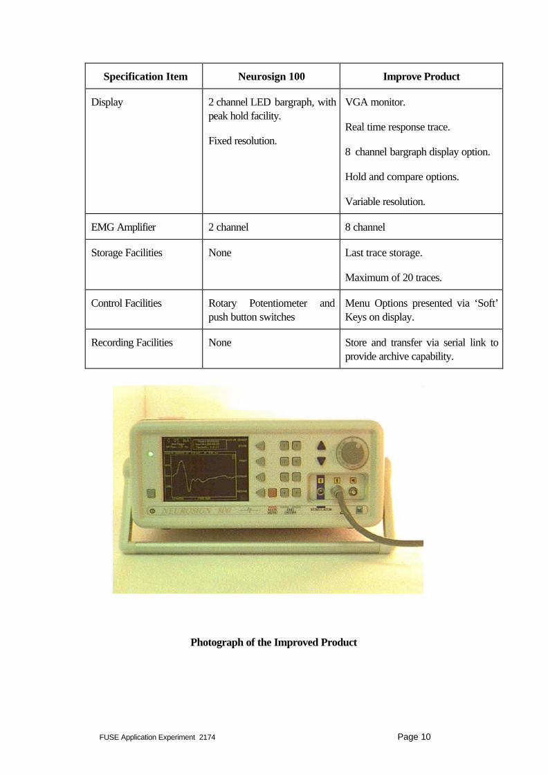
A comparison of the specification of Neurosign 100 and the improved product is provided inthe following table.
FUSE Application Experiment 2174 Page 10
Specification Item Neurosign 100 Improve Product
Display 2 channel LED bargraph, withpeak hold facility.
Fixed resolution.
VGA monitor.
Real time response trace.
8 channel bargraph display option.
Hold and compare options.
Variable resolution.
EMG Amplifier 2 channel 8 channel
Storage Facilities None Last trace storage.
Maximum of 20 traces.
Control Facilities Rotary Potentiometer andpush button switches
Menu Options presented via ‘Soft’Keys on display.
Recording Facilities None Store and transfer via serial link toprovide archive capability.
Photograph of the Improved Product

FUSE Application Experiment 2174 Page 11
FUSE Application Experiment 2174 Page 12
7. Choices and rationale for the selected technologies, tools and methodologies
The requirement to display the EMG waveforms could have been met by two differentmethods. The first of these is the use of a software driven device, such as a microprocessor ormicrocontroller, in conjunction with a bitmapped display device such as a raster scanned CRT,or one of the flat panel display technologies (LCD, Plasma, Electroluminescent). Thealternative method would utilise hardware alone, and is similar to the techniques used in manystorage oscilloscopes. The data is digitised, and stored in a memory buffer. The display isgenerated on a vector CRT, by clocking the data out of the memory buffer, via a digital toanalogue coverter, to drive the CRT’s “Y” deflection amplifier whilst the electron beam isscanned across the screen in the “X” direction.
The former method was chosen for the Neurosign monitor, for the following reasons:
1) The use of a processor offers the greatest flexibility for the presentation of the data. Forexample it will be relatively straightforward to compare the current waveform with areference waveform stored earlier.
2) Text and cursors are relatively easy to incorporate on the screen, allowing the measurementof amplitude and latency.
3) The cost of implementing the processor based solution is much lower than that for thehardware solution.
4) The use of a processor brings with it easy, random access to memory for the storage ofwaveform data.
5) The system will allow for future enhancements, such as the incorporation of digital signalprocessing to automatically detect amplitude and latency.
The choice of display technology was influenced, primarily by “viewability”, but also byflexibility, cost and size. CRTs were discounted, because of the relatively high volume that theyrequire, and because small displays (150cm, diagonal) are relatively expensive. LCDs werediscounted because they are not suitable for viewing from a variety of angles, or from anydistance. Plasma displays are expensive, so this left electroluminescent panel displays as themost cost effective choice.
The choice of a suitable processor was more difficult as there is a vast array of devicesavailable, ranging from simple, more or less self contained microcontrollers, 8, 16 and 32 bitmicroprocessors and digital signal processors.
Microcontrollers were considered, particularly as they come equipped with useful built inperipherals, such as serial ports, timers etc. However, they were ultimately discounted becausethe system requires a fairly wide address space in order to interface the data storage RAM.True microcontrollers are really intended to use their own ‘on chip’ memory. Many can beconfigured to operate in microprocessor mode, using external memory, but when this is doneaccess to other on chip peripherals is compromised as the I/O pins used are shared betweenthe two functions.

FUSE Application Experiment 2174 Page 13
Digital signal processors were also rejected because they are highly optimised for theprocessing of digital signal data. Whilst this would have been extremely convenient for handlingthe large amount of EMG data, it would have made interfacing to a display quite cumbersomeand awkward. However, the primary purpose of incorporating a processor into theNeurosign® was to add a display, so a more general purpose device was considered to be abetter choice.
16 bit sampling is used to digitise the EMG signals, in order to maintain adequate resolutionover the dynamic range (approximately 200:1). If an 8 bit processor were to be used, tworead operations would be required for every sample digitised, whereas a 16 bit device wouldrequire just one. If the data rate was relatively low, this would not present a problem, butfaithful reproduction of the EMG signal requires a bandwidth of at least 5kHz (the Neurosign100 has a bandwidth of 10kHz). A data sampling rate of 10kHz gives a maximum bandwidthof 5kHz, by Nyquist, which is a reasonable compromise. There are 8 channels of data, so a16 bit microprocessor would have to perform 80,000 read operations per second, whichwould increase to 160,000 for an 8 bit device. This poses a significant overhead, so a 16 bitmicroprocessor seemed the most appropriate choice, as the overhead is halved. Furthermore,16 bit devices are designed to handle data a word at a time, rather than a byte at a time,making any further processing of the data easier in a 16 bit part.
The selection of 16 bit microprocessors currently available is still bewildering. The ideal devicewould allow simple interfacing with external memory, yet would incorporate integratedperipherals (DMA, serial I/O, timers, etc), to minimise the complexity and cost of the finaldesign. The final choice was Hitachi’s H8/300 which incorporates memory management andaddressing on chip, as well as DMA, asynchronous and synchronous serial ports, parallel I/Oports and programmable timers.
The program was written in the ‘C’ language. Assembly language was also used for a fewsections of the program where speed of execution was critical. The choice of a sufficientlypowerful microprocessor meant that this was only necessary in relatively few instances. Thecode was developed on a PC using Hitachi’s development tools (‘C’ cross-compiler) linked toa ROM emulator, which allowed the program to be downloaded to the prototype for testing.All of the software (including the specifications) was controlled under the MKS version controlsystem.
8. Expertise and experience in microelectronics of the company and the staff allocated tothe project
The Magstim Company Ltd. manufactures two types of product; the Neurosign® 100 NerveMonitoring System and a range of Magnetic Nerve Stimulators. The company hasconsiderable experience of the international regulations and standards that affect medicalequipment. It has established an accredited quality system in line with EN ISO 9001 andEN46001, and was has been certified as a manufacturer of Magnetic Nerve Stimulators andNerve Monitors in compliance with the Medical Devices Directive (93/42/EEC).

FUSE Application Experiment 2174 Page 14
The engineer allocated to the project was involved in the development of these products. Theengineering experience of this individual included technical expertise in analogue circuit design,high power switching, basic logic (ie: TTL) and PCB design. However, the engineer had noexperience of designing products that include embedded microprocessors or microcontrollers,or in software systems development.
9. Workplan and rationale
The workplan originally developed was by its nature a relatively high level overview of theanticipated project activity. Before embarking on the experiment, this workplan was brokendown into considerably more detail, to produce the project plan, but the basic structure did notchange.
The rationale behind the plan was to focus on planning, specification and system design, so thatthe functional requirements, implementation details, interactions and interdependencies of eachof the hardware and software components were defined. Once this had been achieved, theimplementation could be expected to be a straightforward “handle turning” exercise, and wouldavoid the unforeseen interactions that are the most common cause of software bugs.Furthermore, the chances of having to make compromises on the system performance late inthe project due to underestimating the system requirements, would be minimised.
The key phases of the application experiment were as follows:
1. SpecificationDuring this phase, the detailed specifications that were to define the improvedNeurosign® Nerve Monitor were developed. The role of the subcontractor in thisphase of the application experiment was to ensure that formal specification methods forthe specification process were adopted at all times during the specification process.This included the organisation and chairing of formal specification review meetings,identification of action areas, the design and management of resolution actions for thespecification, and the provision of technical advice in the software specification area.This included defining the content, structure and detailed requirements for the softwaredocuments.
The specifications produced consisted of the following specification documents:
1.1. Requirement SpecificationThe requirement specification is the most general of the specification documents.It defines the features and the performance of the system that are necessary forit to fulfill the needs of the intended market. This document was completed inmonth 1 of the application experiment and required 3 days company effort.
1.2. System Functional Specification
FUSE Application Experiment 2174 Page 15
This document defines in broad terms how the proposed design will meet therequirement specification, and identifies the roles played by the variouscomponents (ie: hardware, software, etc) within the system. The specificationwas completed in month 1 and required 12 person days effort.
1.3. Selection / Specification of Experimental componentsThe experimental component is an embedded microprocessor system and digitaldisplay. The most appropriate devices to implement such a sub-system (ie:Microprocessor, display and driver, memory, analogue to digital converter, etc)had to be selected, once the required performance had been defined in thefunctional specification. The company used 5 person days effort in thecomponent specification, and the task was completed in month 2.
1.4. Embedded Software Functional SpecificationThe functional specification for the embedded software defines the overallstructure of the software, as well as its features, both in terms of the “Man-Machine” interface, and of the specific tasks that the software will be required toperform. Furthermore, it defines how each task or set of tasks will be brokendown into modules, and how they will communicate. This task required 14person days effort in months 3 and 4 of the application experiment.
1.5 Module specifications for Embedded SoftwareEach software module that was identified in the embedded software functionalspecification is specified in detail. The purpose of the module, any algorithms tobe used, the expected input conditions and the form of any outputs are the typesof characteristics that are defined by these documents. This task was undertakenduring months 5 and 6 of the application experiment and required 31 persondays of company engineering resource.
2 System DesignThe set of tasks encompassed by system design takes the specifications and translatesthem into a prototype. The role of the subcontractor in this task was to assist thecompany in the selection of the processor technology, specification of the overallsystem architecture, assistance in partitioning functions to hardware and softwaredesigns, and in providing detailed design support as required. This included theundertaking of the circuit board layout design.
2.1 Hardware designThe hardware components (embedded microprocessor, display, analogue signalprocessing, etc) were brought together in a design that meets the requirementsdefined in the functional specification. The end result of this process being a setof schematic diagrams that describe the hardware. The task was completedduring months 3 to 5, and required 28 person days of company engineeringeffort in total.
FUSE Application Experiment 2174 Page 16
2.2 PCB DesignThis task is the design of a printed circuit board to implement the hardwaredesign. Due to the complexity of the hardware design (>70 integrated circuits), itis not cost effective to attempt to build a hand wired “breadboard” to prove thedesign. This was one task were the project deviated from the original plan. Itbecame clear that the time allocated for the PCB design (3 man weeks) wastotally inadequate for a board of this nature. Given that the company’s CADtools required the user to manually track all the connections, a more realistictime-frame would have been 6 weeks. In order to prevent the project frombeing delayed, the company purchased an auto-router as an adjunct to its CADtools. Using this tool, the PCB design was accomplished by the subcontractorwithin the 3 week period, in month 6 of the application experiment.
2.3 Software DesignThis task covers the intermediate stage between the specification and the writingof the final code. The software structure, data flow, etc. is designed usingtechniques such as pseudo-code, flow diagrams etc. This forms a blueprint ortemplate, so that when it comes to creating the code, it should simply be a caseof translating the design into the final programming language. The task wasundertaken in months 6 to 7 of the application experiment, and required 22person days engineering effort.
2.4 Software codingThis is the final stage in the creation of the prototype software. The bulk of thecode was written in the “C” language, although some time-critical modules werewritten in assembler. The coding activity required 54 person days in months 8, 9and 10 of the application experiment.
3 Prototype Evaluation and TestingThis final group encompasses the tasks that are necessary to bring all of the componentparts together to produce a prototype of the instrument. It also included the subsequenttesting of that prototype to ensure that it not only functions as intended by design(verification), but that it will also meet the requirements of the end user (validation).
The role of the subcontractor in these tasks was to:• Assist in the definition of the test procedures, test methods and documentation
procedures for these tests.• Assistance to functional testing by the provision of expert design assistance a
required.• Assistance in resolving design issues located during the prototype test phase.
3.1 Prototype production The various physical components that make up the system have to be obtained,
and a prototype built. In practice, two prototypes were built at this stage, andthis required 10 person days in months 7 and 8 of the application experiment..

FUSE Application Experiment 2174 Page 17
3.2 Test SetupA set of test specifications and methods were created, against which theperformance of the prototype could be verified. This task required 12 persondays engineering effort.
3.3 Functional TestingThe various hardware sub-systems were tested against the test specifications, toverify that they were performing as intended (eg: verify that the 5 volt powersupply is supplying 5 volts, and that it can do so over the designed supplycurrent range). Not surprisingly, a number of minor modifications were made atthis stage, where it was found that the hardware was not performing quite asintended. This was foreseen, and sufficient time had been allowed in the plan.Nine person days of engineering resource were required in the eighth month ofthe application experiment.
3.4 Prototype TestingOnce the performance of the sub-systems, was verified, the performance of themonitor as a whole was verified. Again, not everything was found to workexactly as planned, and in this instance a number of software bugs wereuncovered. Some of these were “typographical” in nature, and some were dueto minor flaws in the design logic. However, given the design processes that hadbeen employed in developing the software, none of these proved hard toovercome. Prototype testing required 18 person days in month 11 of theapplication experiment.
3.5 Field TestingThis is the testing of the prototype under the conditions where it is intended tobe used, (ie: on patients undergoing surgery) and was the primary reason whytwo prototypes were constructed. This allowed one monitor to be used in thefield, whilst the other remained in house. 10 person days were spent on thistask.
4 Project ManagementThis was an ongoing task throughout the application experiment. Frequent reviewmeetings were held to assess the progress of the project and to ensure that it remainedon track. The total company effort in terms of person days was 24 person days.
Subcontractor input to the technical management of the programme was substantial,and involved the definition of the philosophy to be adopted for the applicationexperiment. The presence of the subcontractor also meant that the approach ofthorough specification before designing anything was maintained, even when progressappeared ‘slow’.
5 TrainingDuring the early stages of the application experiment, the company’s engineer attendeda 3 day formal training course on “Specifying and Managing Software Requirements”.

FUSE Application Experiment 2174 Page 18
This then formed an excellent foundation upon which the remainder of the training couldbuild. This latter training took the form of “on the job” training from the sub-contractoras each task progressed.
Subcontractor assistance in training also occurred throughout the applicationexperiment, and provided the company engineer with on-going design advice in thestructuring of software solutions.
6 Other TasksThere were a number of other tasks that had to be completed if the applicationexperiment was to yield a real medical monitoring instrument. None of these is as aresult of incorporating a microprocessor into the instrument, so were seen as beingoutside the scope of the proposal. Nonetheless, they still had to be done alongside thetasks described above. Examples of these tasks are; mechanical design of a suitableenclosure, safety standard compliance testing and EMC testing.
Deviations from Workplan: The application experiment proceeded remarkably closely tothe plan. The reasons for this was the use of a regular review process elaborated upon in thefollowing sections. The only slight deviations from the work plan were:
1. A slight delay in the availability of the prototype hardware; this was overcome because theoriginal work plan scheduled software design and coding in parallel to the prototypehardware build, and this meant the critical path for the project was not affected.
2. The need to shorten the time taken for PCB layout design. This was achieved by the useof the subcontractor and more advance auto routing CAD systems to shorten the plannedtime required.
3. Difficulty in organising clinical trials meant that the field trials were slightly delayed.
Subcontractors Contribution: The subcontractors effort into the application experimentwas 42 person days at an approximate cost of 18 KECU. The subcontractor’s time wasspent in:
1. Technical Specification, including 8 person days defining software specifications.
2. Hardware Design (including PCB layout): 12 person days
3. Technical Reviews (including Software Reviews): 10 person days
4. Test and evaluation: 5 person days.
5. Provision of on the job training in these tasks.
The actual workplan adopted is shown in the following illustration. The role of thesubcontractor support is shown in the parallel tasks, especially in the areas of hardware designand PCB layout.

FUSE Application Experiment 2174 Page 19
Actual Workplan Adopted for the Application Experiment
The subcontractor’s role can, in general, be summarised as one of the provision of technicaladvice, expert review assessments and in terms of assistance to project planning andmanagement. This reflected the philosophical approach to the project implementation outlinedin subsequent sections.
The resources used in the application experiment were as follows:
Task Company ActualEffort
(person days)
Cost of subcontractor(KECU)
Technical Management 24 1.5Specification 65 4.8Training 6 2.27Design 104 8.82Evaluation and Testing 59 2.3
Total 258 19.69
Table 2: Resources Used in the Prototype Unit Development
10. Subcontractor information
Throughout the application experiment, the company employed the services of DyMed, a smallconsultancy specialising in the design of Electro-medical equipment.
Task Project Months
1 2 3 4 5 6 7 8 9 10 11 12 Requirements SpecificationSystem Functional SpecificationComponent specificationSoftware Functional SpecificationModule SpecificationsHardware DesignPCB DesignSoftware DesignSoftware CodingPrototype ProductionTest Set UpFunctional TestingPrototype TestingField TestingTraining
FUSE Application Experiment 2174 Page 20
The main characteristics identified for the selection of a subcontractor was prior medicalproduct design, familiarity with medical equipment approval procedures, local support, andexperience in the new technical areas of microprocessor and embedded software design. Thislist of desirable characteristics narrowed the field of selection considerably, and DyMed wasthe only local support subcontractor providing all of this expertise.
The subcontractor was selected on the basis of the experience of the principle partner, Dr. M.Polson, who had acquired over 15 years of experience of developing products for companiesin the Medical Instrumentation industry, prior to founding DyMed. Specific areas of expertiserelevant to this application experiment were his experience in:
• Analogue design,• Physiological signal acquisition,• Interfacing to medical transducers,• Embedded microprocessors/microcontrollers,• Software design,• Embedded software (firmware),• International regulatory requirements,• EC Medical devices directive,• USA FDA requirements.
Dr. Polson’s role was to provide guidance and on the job training as the application experimentprogressed. This was accomplished by a combination of “up front” schooling in the methodsand practices applicable to a particular task, prior to that task being started, and subsequentreview and critique during the implementation and upon completion of each task.
A second subcontractor was employed to provide a formal training course to the company’sengineer. This company was Learning Tree International; an international provider of trainingwithin the fields of information technology and microelectronics. The course provided wasentitled “Specifying and Managing Software Requirements”.
11. Barriers perceived by the company in the first use of the proposed technology
Prior to this application experiment, the Magstim Company Ltd had not developed a productwhich incorporated an embedded microprocessor. However, the reason for this was primarilythat the company did not believe that this technology offered a cost effective solution to itsrequirements. In order to reach this conclusion, the company had previously compared themerits of the discrete hardware approach with a microprocessor based design, so it was notcompletely naive regarding the latter.
The need to add waveform display and data storage capabilities to the Neurosign® Nervemonitor changed this view. In assessing the development of this type of product, the companyidentified a few of minor barriers, such as acquiring the hardware design skills and the cost ofdevelopment tools. However neither of these was perceived as insurmountable.
FUSE Application Experiment 2174 Page 21
There was, however, one major barrier pertaining to software development. The nature of thisbarrier encompassed knowledge and technology (ie: could the company acquire the necessaryskills), psychology (ie: would the software be plagued by bugs, causing delays) and finance (ie:would development delays cause a substantial cost overrun).
The source of these fears was twofold:
1) The company knew of a number of other companies in the Electro-medicalinstrumentation business have run into difficulties developing software driven devices,ranging from severely underestimating the amount of time and resource required todevelop the product, to the burden of field upgrades to correct bugs and the resultingnegative impression that this leaves with customers.
2) One area with considerable expertise in software development is those companies whoseproduct is commercial applications software for the mass PC market, yet it is widelyknown that even these companies suffer substantial delays in product development, oftenmissing their target launch dates by many months.
Consequently, the company felt that to embark on a product development that incorporated asignificant software component would represent a high risk. How could it manage thedevelopment to minimise these risks?
12. Steps taken to overcome barriers and arrive at an improved product
The process of overcoming the barriers facing the Magstim Company started with thepreparation of the FUSE project proposal. During this period, the company worked closelywith a subcontractor to develop a strategy to minimise the risks involved in developingsoftware, and to ensure that following the completion of the experiment, the skills necessary forthe successful development and subsequent maintenance of embedded software would havebeen transferred to the company.
The plan which was developed was to use the Magstim Company’s own engineering staff tocomplete the “hands on” design work for the new hardware and software under the guidanceof a subcontractor, who had prior experience of this type of development. This way, trainingwould be a continual process throughout all the phases of the application experiment, andwould ensure that, by the end of the experiment, the company had acquired all of the basicskills necessary to both support the newly developed product and to make use ofmicroprocessor technology in future designs.
This approach dealt with the minor barrier of acquiring the skills, but did not fully address themore significant barrier relating to the pitfalls of software development. This was not astraightforward barrier to overcome, but the process was made easier by the company’saspiration to introduce the new technology. In fact, it was not possible to fully remedy thissituation prior to embarking on the application experiment, although the company’sapprehension was reduced by assurances from the subcontractor that the risks could beminimised by detailed specification and design planning in the initial stages of the project.

FUSE Application Experiment 2174 Page 22
In planning the application experiment, this process was adopted. However, as the projectprogressed, the company management started to feel increasingly uneasy about the fact thatconsiderable amounts of manpower were being expended designing and specifying thesoftware, but there was no code being written, so there was nothing tangible, (like aprototype), to reassure them that progress was being made.
Being familiar with developing hardware based instruments, the company was used to seeingparts of the design “bread-boarded” as the development process went along. However, thistechnique is not generally appropriate when developing software, and certainly was not themethod that had been planned.
Under normal circumstances, this pressure to “show something working” may have beenirresistible, and the company would have fallen into the trap of producing code too early,before the design phase was complete, which is the primary cause of unforseen bugs or codethat does not meet the requirements. As it was, the risks were mitigated by the fact that theproject was being funded as an application experiment, so the company was persuaded to stickto the plan, and reserve judgement of its success or failure until the end.
13. Knowledge and experience acquired
The aim of the company and the subcontractor was to enable a continuous transfer ofknowledge and skills throughout the experiment, so that when it was over the company wouldhave acquired all of the basic skills necessary to both support the device that had beendeveloped during the experiment, and to make use of embedded microprocessor technology infuture product designs. Specifically, these skills include:
• Microprocessor system hardware design,• Software design and documentation techniques,• Software coding skills,• Software configuration (version) control,• Design verification and validation methods.
The application experiment has been successful in achieving this goal. In addition to developingan exciting new product, the company has acquired a sufficient set to skills to allow it to feelconfident that it can both supporting and enhancing the product, as well as apply embeddedmicroprocessor technology to future products, wherever it is cost effective to do so.
14. Lessons learned
The key lesson learned has been the value of rigorous and detailed specification and systemdesign phases in the project.
FUSE Application Experiment 2174 Page 23
Traditionally, a prototype would have been designed and constructed as early as possibleduring the project. Subsequently it would have been modified and “tweaked” in order to deliverthe required performance. The primary reason for this approach is that it makes bothmanagement and the development team feel a sense of security, as there is something tangibleto show that the project is making progress. Whilst this may work for relatively simple designs,as the system becomes more complex the chances that this approach will deliver anything closeto an optimal design in the shortest possible time become increasingly remote.
During this project, a considerable amount of effort was expended in developing detailedsystem specifications and subsequently the high level system design. This meant that when thedetailed design started, all of the interactions between the different components on the system(both hardware sub-systems and software modules) had been designed. Consequently thedetailed design and software coding progressed rapidly, and when the hardware and softwarewere integrated, the system functioned as intended the first time (barring a few minor mistakesthat were quickly corrected).
The biggest problem was resisting the pressure from management, whose perception was thatno progress was being made during the early phases. The company has now learnt that theeffort expended working out how the system will work before lifting a soldering iron or writinga single line of code, pays for itself in the long run.
The second important lesson learned was the value of timely project reviews, throughout thedevelopment process. Early recognition that something has changed, or is not going accordingto plan enables corrective action to be taken, before the consequences become disastrous. Forexample, once the hardware design had been completed, it became obvious that the amount oftime budgeted to design the printed circuit board was completely inadequate. If the company’sengineer had had to undertake this design, (as was originally planned), a delay of 4 to 6 weekswould have been incurred. In order to avoid this, the company purchased an auto-router toenhance its existing printed circuit CAD tools and asked the subcontractor to implement thedesign.
The success of the design reviews is highly dependant on the way in which they are conducted,and the atmosphere which prevails. It is vital that the meetings remain objective, forwardlooking and focus on problem solving. It is difficult enough for any member of the team toreveal a problem in front of his or her peers, but if they are subsequently made to feel like ascapegoat and the meetings degenerate into a witch-hunt, then they will not do so. At thispoint, the meetings become worthless. The strength of the technique lies in identifying problemsas early as possible, before they become disasters, and taking corrective action early enough.This can only happen with the cooperation of every member of the project team.

FUSE Application Experiment 2174 Page 24
15. Resulting product, its industrialisation and internal replication
The industrialisation of a product for the medical field requires a significant amount of pre-planning in order for the information required for regulatory and medical approval to berecorded. The company therefore began the process of industrialisation early in the designprogramme by the planning of medical field trials of the equipment and in the recording ofdesign data to meet the needs of the Medical Approvals bodies. The approximate costsassociated with gaining these approvals are estimated at 10 KECU.
In parallel with the electronic design the company invested in the mechanical design of theenclosure was undertaken. This was essential to enable the operator interface softwarerequirements to be defined. The company estimates tooling and fabrication costs for prototypeenclosures to be approximately 17 KECU. Advertising and marketing promotional literaturewas also produced in these timescales.
The company now has all the necessary skills to apply this type of technology.
At the outset of the application experiment, the company had identified a real market need thatcould best be fulfilled by the addition of embedded microprocessor technology to one of itsproducts; the Neurosign® 100 Nerve Monitor. Consequently, the company proceeded tointroduce the new product into production after the final prototype evaluations were complete.
The improved product is now being sold, and has achieved export sales to the USA. Thefinancial impact of these sales are discussed in the following section.
FUSE Application Experiment 2174 Page 25
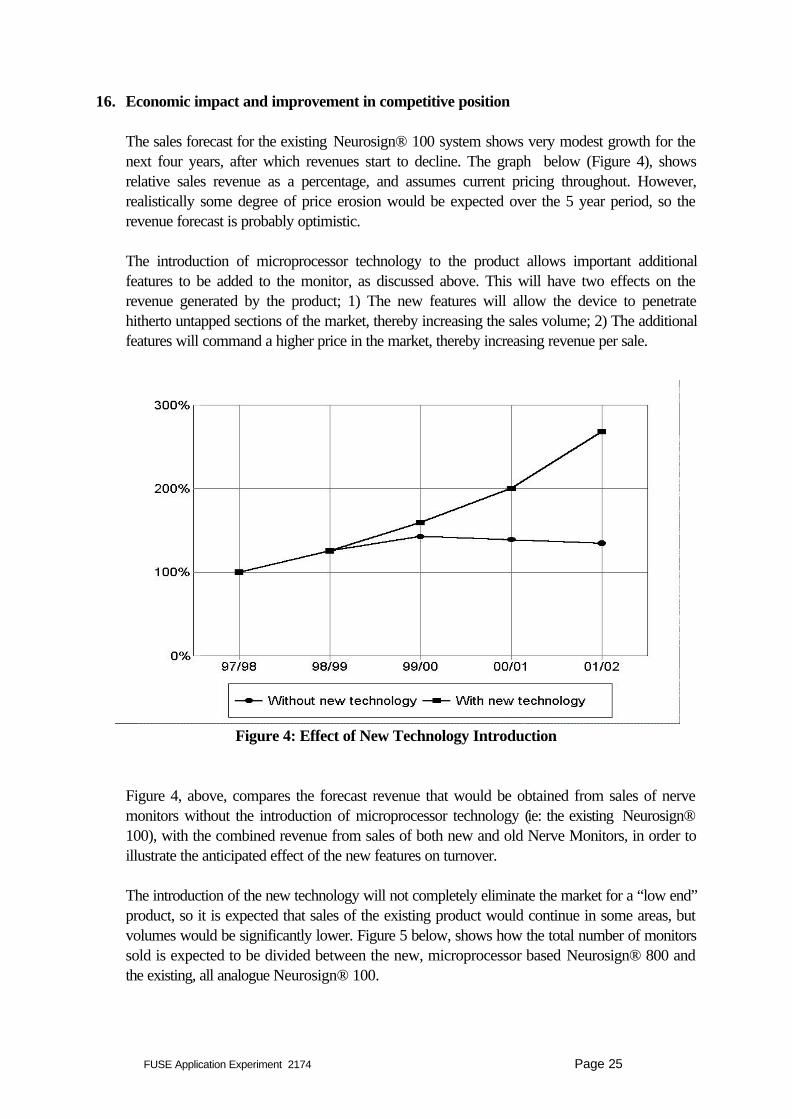
16. Economic impact and improvement in competitive position
The sales forecast for the existing Neurosign® 100 system shows very modest growth for thenext four years, after which revenues start to decline. The graph below (Figure 4), showsrelative sales revenue as a percentage, and assumes current pricing throughout. However,realistically some degree of price erosion would be expected over the 5 year period, so therevenue forecast is probably optimistic.
The introduction of microprocessor technology to the product allows important additionalfeatures to be added to the monitor, as discussed above. This will have two effects on therevenue generated by the product; 1) The new features will allow the device to penetratehitherto untapped sections of the market, thereby increasing the sales volume; 2) The additionalfeatures will command a higher price in the market, thereby increasing revenue per sale.
Figure 4: Effect of New Technology Introduction
Figure 4, above, compares the forecast revenue that would be obtained from sales of nervemonitors without the introduction of microprocessor technology (ie: the existing Neurosign®100), with the combined revenue from sales of both new and old Nerve Monitors, in order toillustrate the anticipated effect of the new features on turnover.
The introduction of the new technology will not completely eliminate the market for a “low end”product, so it is expected that sales of the existing product would continue in some areas, butvolumes would be significantly lower. Figure 5 below, shows how the total number of monitorssold is expected to be divided between the new, microprocessor based Neurosign® 800 andthe existing, all analogue Neurosign® 100.

FUSE Application Experiment 2174 Page 26
Figure 5. Relative Number of Units Sold
The effect on revenue is more dramatic, because the additional features incorporated in the newproduct mean that it can command a higher selling price. The forecast revenue obtained fromthe two products is plotted in figure 6, which shows that the new, microprocessor basedproduct will ultimately be generating more than four times the revenue of the existing nervemonitoring product line.
Figure 6: Relative Numbers of Units Sold
FUSE Application Experiment 2174 Page 27
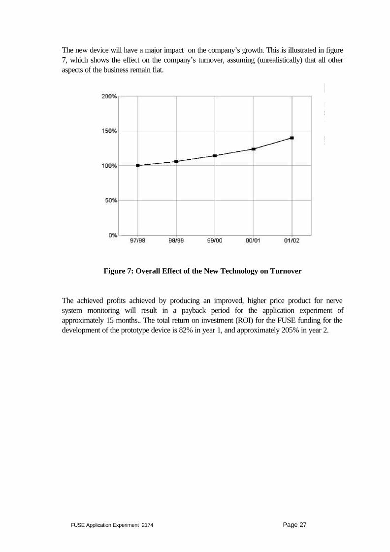
The new device will have a major impact on the company’s growth. This is illustrated in figure7, which shows the effect on the company’s turnover, assuming (unrealistically) that all otheraspects of the business remain flat.
Figure 7: Overall Effect of the New Technology on Turnover
The achieved profits achieved by producing an improved, higher price product for nervesystem monitoring will result in a payback period for the application experiment ofapproximately 15 months.. The total return on investment (ROI) for the FUSE funding for thedevelopment of the prototype device is 82% in year 1, and approximately 205% in year 2.

FUSE Application Experiment 2174 Page 28
17. Target audience for dissemination throughout Europe
The aim of this application experiment was to gain first use experience in the introduction ofembedded microprocessor technology into existing analogue equipment. As such, the range ofcompanies that are likely to benefit from the dissemination of information about this experiment,is considerably broader than the field of Electro-medical instrumentation. Consequently, inaddition to companies involved in the manufacture of medical, precision and optical instruments(Prodcom code 331), companies in the following sectors may find the information beneficial:
Energy production and distribution; gas & water supply (prodcom 41),Machinery, electrical and optical equipment (Prodcom 29),Industrial process control systems (Prodcom 333)
Additionally, the experience of introducing microprocessor technology into the highly regulatedarea of medical electronics will be of interest to other organisations operating in a safety criticalindustrial sectors, such as:
Transport products (Prodcom code 35)Mining and quarrying (Prodcom code 14)
The target audience is expected to include directors, technical managers and engineers in smallor medium sized enterprises considering the implementation of microprocessor technology intheir products for the first time.