fuel injection systems
TRANSCRIPT
Fuel Injection Systems 7 I DEFINITION
Fuel injection is the introduction of fuel or a fuel-air (F/ A) mixture into the induction system of an engine or into the combustion chamber of each cylinder by means of a pressure source other than the pressure differential created by airflow through the venturi of a carburetor. The usual pressure source is an injection pump, which comes in several types. A fuel injection carburetor discharges the fuel into the airstream at or near the carburetor. A fuel injection system discharges the fuel into the intake port of each cylinder just ahead of the intake valve or directly into the combustion chamber of each cylinder.
Fuel injection systems have a number of advantages:
1. Freedom from vaporization ic ing, thus making it unnecessary to use carburetor heat except under the most severe atmospheric conditions
2. More uniform delivery of FIA mixture to each cylin-der
3. Improved control of F/A ratio 4. Reduction of maintenance problems 5. Instant acceleration of engine after idling, with no
tendency to stall 6. Increased engine efficiency Fuel injection systems have been designed for all types
of reciprocating aircraft engines. They are presently used on a wide variety of light engine airplanes, large commercial aircraft, helicopters, and military aircraft.
The Continental fuel injection system is a multinozzle, conrinuous-fiow type which controls fuel flow to match engine airflow. The fuel is discharged into the intake port of each cyl inder. Any change in ai r throttle position or engine speed, or a combination of both, causes changes in fuel flow in the correct relation to engine airflow. A manual mixture control and a pressure gage, indicating metered fuel pressure, are provided for precise leaning at any combination of altitude and power. Since fuel flow is directly proportional to metered fuel pressure, the settings can be predetermined and the fuel consumption accurately predict-
ed. The continuous-flow system permits the use of a typical rotary-vane fuel pump in place of a much more complex and expensive plunger-type pump. There is no need for a timing mechanism because each cylinder draws fuel from the discharge nozzle in the intake port as the intake valve opens.
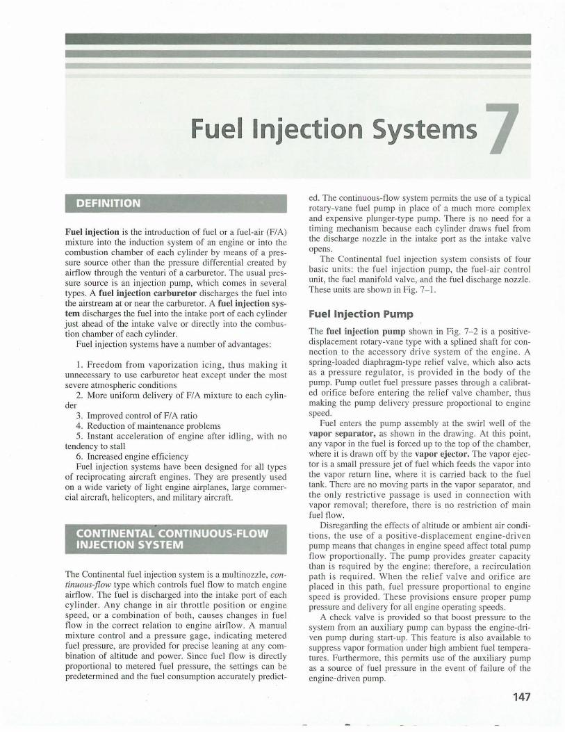
The Continental fuel injection system consists of four basic units: the fuel injection pump, the fuel-air control unit, the fuel manifold valve, and the fuel discharge nozzle. These units are shown in Fig. 7-1.
Fuel Injection Pump
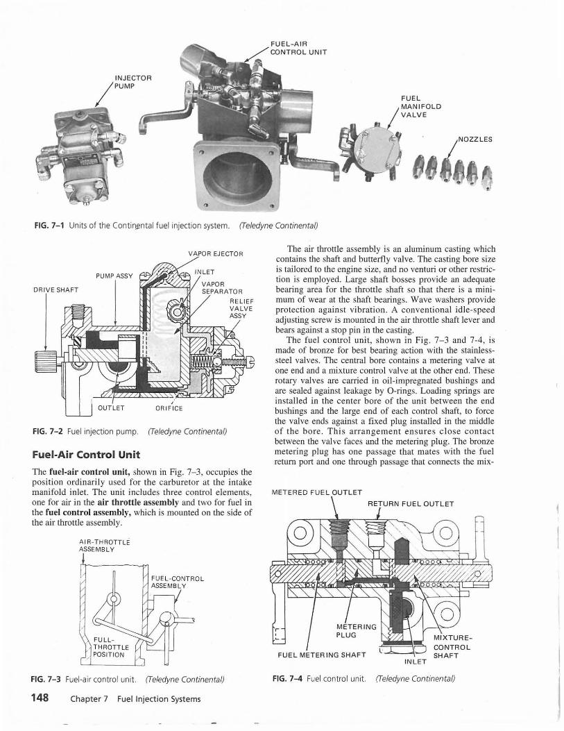
The fuel injection pump shown in Fig. 7-2 is a positivedisplacement rotary-vane type with a splined shaft for connection to the accessory drive system of the engine. A spring-loaded diaphragm-type relief valve, which also acts as a pressure regu lator, is provided in the body of the pump. Pump outlet fuel pressure passes through a calibrated orifice before entering the relief valve chamber, thus making the pump delivery pressure proportional to engine speed.
Fuel enters the pump assembly at the swirl well of the vapor separator, as shown in the drawing. At this point, any vapor in the fuel is forced up to the top of the chamber, where it is drawn off by the vapor ejector. The vapor ejector is a small pressure jet of fuel which feeds the vapor into the vapor return line, where it is carried back to the fuel tank. There are no moving parts in the vapor separator, and the only restrictive passage is used in connection with vapor removal; therefore, there is no restriction of main fuel flow.
Disregarding the effects of altitude or ambient air conditions, the use of a positive-displacement engine-driven pump means that changes in engine speed affect total pump flow proportionally. The pump provides greater capacity than is required by the engine; therefore, a recirculation path is required. When the relief valve and orifice are placed in this path, fuel pressure proportional to engine speed is provided. These provisions ensure proper pump pressure and delivery for all engine operating speeds.
A check valve is provided so that boost pressure to the system from an auxiliary pump can bypass the engine-driven pump during start-up. This feature is also available to suppress vapor formation under high ambient fuel temperatures. Furthermore, this permits use of the auxiliary pump as a source of fuel pressure in the event of failure of the engine-driven pump.
147
•
FU EL
!.MA NIFOLD VA LVE
I.:
FIG. 7-1 Units of the Conti~ntal fuel injection system. (Teledyne Continental)
VAPOR EJECTOR
PUMP ASSY
DRIVE SHAFT
,. OUTLET OR IF ICE
FIG. 7- 2 Fuel injection pump. (Teledyne Continental)
Fuel-Air Control Unit
RELIEF VALVE ASSY
The fuel-a ir control unit, shown in Fig. 7-3, occupies the posi tion ordinarily used for the carburetor at the intake manifold inlet. The unit includes three control elements, one for air in the air throttle assembly and two for fuel in the fuel control assembly, which is mounted on the side of the air throttle assembly.
AIR-THR·OTTLE ASSEMBLY
FIG. 7- 3 Fuel-air control unit. (Teledyne Continental)
148 Chapter 7 Fuel Injection Systems
The air throttle assembly is an aluminum casting which contains the shaft and butterfly valve. The casting bore size is tailored to the engine size, and no venturi or other restriction is employed. Large shaft bosses provide an adequate bearing area for the throttle shaft so that there is a minimum of wear at the shaft bearings. Wave washers provide protection against vibration. A conventional idle-speed adjusting screw is mounted in the air throttle shaft lever and bears against a stop pin in the casting.
The fuel control unit, shown in Fig. 7-3 and 7-4, is made of bronze for best bearing action with the stainlesssteel valves. The central bore contains a metering valve at one end and a mixture control valve at the other end. These rotary valves are carried in oil- impregnated bushings and are sealed against leakage by 0-rings. Loading springs are installed in the center bore of the unit between the end bushings and the large end of each control shaft, to force the valve ends against a fixed plug installed in the middle of the bore. Thi s arrangement ensures close contact between the valve faces and the metering plug. The bronze metering plug has one passage that mates with the fuel return port and one through passage that connects the mix-
METERED FUE L OUTL ET
FUE L METERING SHAFT INLET
CONTRO L SHAFT
FIG. 7-4 Fuel control unit. (Teledyne Continental)
ture control valve chamber with the metering valve chamber. 0 -rings are used to seal the metering plug in the body.
Each stainless-steel rotary valve includes a groove which forms a fuel chamber. A contoured end face of the mixture control valve aligns with the passages in the metering plug, to regulate the fuel flow from the fuel chamber to the metering valve or to the return fuel outlet. A control lever is mounted on the mixture control valve shaft for connection to the cockpit mixture control. If the mixture control is moved toward the LEAN position, the mixture control valve in the fuel control unit causes additional fuel to flow through the return line to the fuel pump. This reduces the fuel flow through the metering plug to the metering valve. Rotation of the fuel control valve toward the RICH position causes more fuel to be delivered to the metering valve and less to the return fuel outlet.
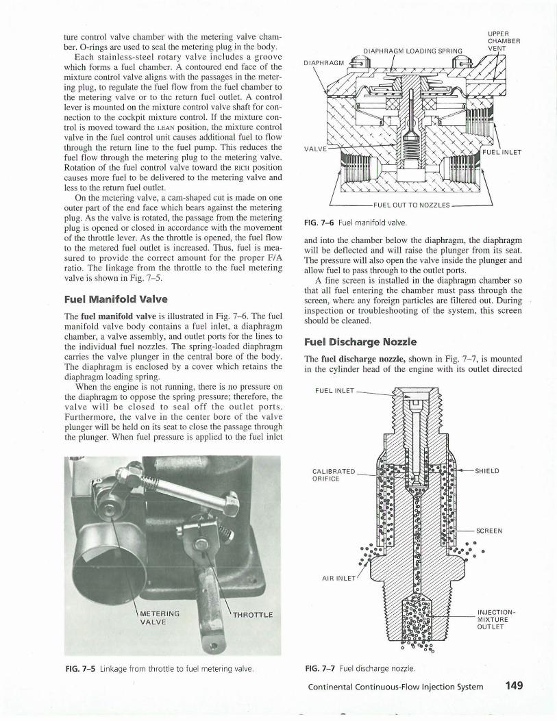
On the metering valve, a cam-shaped cut is made on one outer part of the end face which bears against the metering plug. As the valve is rotated, the passage from the metering plug is opened or closed in accordance with the movement of the throttle lever. As the throttle is opened, the fuel flow to the metered fuel outlet is increased. Thus, fuel is measured to provide the correct amount for the proper F/A ratio. The linkage from the throttle to the fuel metering valve is shown in Fig. 7-5.
Fuel Manifold Valve
The fuel manifold valve is illustrated in Fig. 7-6. The fuel manifo ld valve body contain s a fuel inlet, a diaphragm chamber, a valve assembly, and outlet ports for the lines to the individual fuel nozzles. The spring-loaded diaphragm carries the valve plunger in the central bore of the body. The diaphragm is enclosed by a cover which retains the diaphragm loading spring.
When the engine is not running, there is no pressure on the diaphragm to oppose the spring pressure; therefore, the va lve wi ll be closed to seal off the outlet ports. Furthermore, the valve in the center bore of the valve plunger will be held on its seat to close the passage through the plunger. When fuel pressure is applied to the fuel inlet
FIG. 7- 5 Linkage from throttle to fuel metering valve.
FIG. 7-6 Fuel manifold valve.
UPPER CHAMBER VENT
and into the chamber below the diaphragm, the diaphragm will be deflected and will raise the plunger from its seat. The pressure will also open the valve inside the plunger and allow fuel to pass through to the outlet ports.
A fine screen is installed in the diaphragm chamber so that all fuel entering the chamber must pass through the screen, where any foreign particles are fil tered out. During inspection or troubleshooting of the system, th is screen should be cleaned.
Fuel Discharge Nozzle
The fuel discharge nozzle, shown in Fig. 7-7, is mounted in the cylinder head of the engine with its outlet directed
FIG. 7-7 Fuel discharge nozzle.
INJECT ION-..4<,~-- MIXTURE
OUTLET
Continental Continuous-Flow Injection System 149
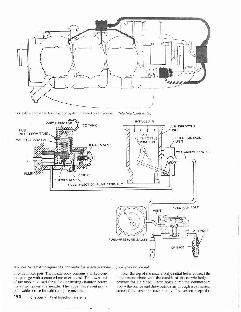
FIG. 7-8 Continental fuel injection system installed on an engine. (Teledyne Continental)
FUEL INLET FROM T AN K
TO TANK
~ORIFICE CHECK VALV~
INTAKE AIR
I
t
FUEL-CONTROL UNIT
TO MAN IFOLD VALVE
FUEL- INJECTION-PUMP ASSEMBLY
FIG. 7- 9 Schematic diagram of Continental fuel injection system.
into the intake port. The nozzle body contains a drilled central passage with a counterbore at each end. The lower end of the nozzle is used for a fuel-air mixing chamber before the spray leaves the nozzle. The upper bore contain s a removable orifice for calibrating the nozzles.
150 Chapter 7 Fuel Injection Systems
fl\
(Teledyne Continental)
Near the top of the nozzle body, radial holes connect the upper counterbore with the outside of the nozzle body to provide for air bleed. These holes enter the counterbore above the orifice and draw outside air through a cylindrical screen fitted over the nozzle body. The screen keeps dirt
and other foreign material out of the interior of the nozzle. A press-fitted shield is mounted on the nozzle body and extends over the greater part of the filter screen, leaving an opening near the bottom. This provides both mechanical protection and an afr path with an abrupt change in direction as an aid to cleanness. Nozzles are calibrated in several ranges, and all nozzles furnished for one engine are of the same range. The range is identified by a letter stamped on the hexagon of the nozzle body.
Complete System
The complete Continental fuel injection system installed on an engine is shown in Fig. 7-8. This diagram shows the fuel-air control unit installed at the usual location of the carburetor, the pump installed on the accessory section, the fuel manifold valve installed on the top of the engine, and the nozzles installed in the cylinders at the intake ports. The simplicity of this system contributes to ease of maintenance and economy of operation. A diagram of the complete system is shown in Fig. 7-9.
To summarize, the Continental fuel injection system utilizes fuel pressure (established by the engine rpm and the relief valve) and a variable orifice (controlled by throttle position) to meter the correct volume and pressure of fuel for all power settings. The mixture is controlled by adjusting the quantity of fuel returned to the pump inlet.
Installations for Turbocharged Engines
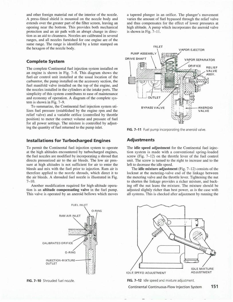
To permit the Continental fuel injection system to operate at the high altitudes encountered by turbocharged engines, the fuel nozzles are modified by incorporating a shroud that directs pressurized air to the air bleeds. The low air pressure at high altitudes is not sufficient for air to enter the bleeds and mix with the fuel prior to injection. Ram air is therefore applied to the nozzle shrouds, which direct it to the air bleeds. A shrouded fuel nozzle is illustrated in Fig. 7-10.
Another modification required for high-altitude operation is an altitude compensating valve in the fuel pump. This valve is operated by an aneroid bellows which moves
FUEL INLET
RAM AIR INLET
CALIBRATED ORIFICE
INJECTION-MIXTURE--~~
OUTLET
FIG. 7-10 Shrouded fuel nozzle.
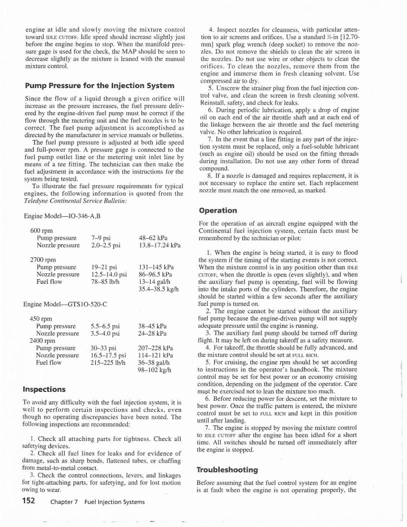
a tapered plunger in an orifice. The plunger's movement varies the amount of fuel bypassed through the relief valve and thus compensates for the effect of lower pressures at high altitude. A pump which incorporates the aneroid valve is shown in Fig. 7-1 l.
INLET
VAPOR SEPARATOR
....._.>+---AN EROID VALVE
FIG. 7-11 Fuel pump incorporating the aneroid valve.
Adjustments
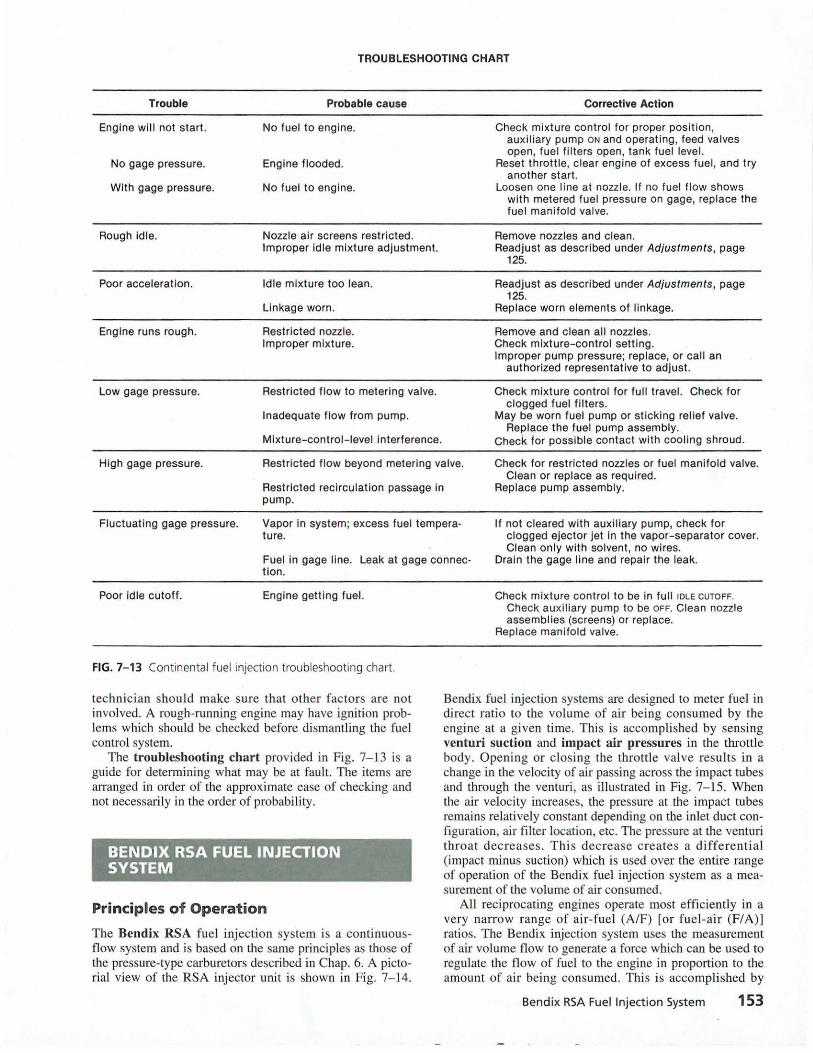
The idle speed adjustment for the Continental fuel injection system is made with a conventional spring-loaded screw (Fig. 7-12) on the throttle lever of the fuel control unit. The screw is turned to the right to increase and to the left to decrease the idle speed.
The idle mixture adjustment (Fig. 7-1 2) consists of the locknut at the metering-valve end of the linkage between the metering valve and the throttle lever. Tightening the nut to shorten the linkage provides a richer mixture, and backing off the nut leans the mixture. The mixture should be adjusted slightly richer than best power, as is the case with all systems. This is checked after adjustment by running the
IDLE SPEED ADJUSTMENT
FIG. 7-12 Idle speed and mixture adjustment.
Continental Continuous-Flow Injection System 151
engine at idl e and slow ly moving the mixture control toward IDLE CUTOFF. Idle speed should increase slightly just before the engine begins to stop. When the manifold pressure gage is used for the check, the MAP should be seen to decrease slightly as the mixture is leaned with the manual mixture control.
Pump Pressure for the Injection System
Since the flow of a liquid through a given orifice will increase as the pressure increases, the fuel pressure delivered by the engine-driven fuel pump musL be correct if the flow through the metering unit and the fuel nozzles is to be correct. The fuel pump adjustment is accomplished as directed by the manufacturer in service manuals or bulletins.
The fuel pump pressure is adjusted at both idle speed and full-power rpm. A pressure gage is connected to the fuel pump outlet line or the metering unit inlet line by means of a tee fitting. The technician can then make the fuel adjustment in accordance with the instructions for the system being tested.
To illustrate the fuel pressure requirements for typical engines, the following information is quoted from the Teledyne Continental Service Bulletin:
Engine Model- I0-346-A,B
600 rpm Pump pressure Nozzle pressure
2700 rpm Pump pressure Nozzle pressure Fuel flow
7- 9 psi 2.0-2.5 psi
19-21 psi 12.5- 14.0 psi 78-85 lb/h
Engine Model-GTS l 0-520-C
450 rpm Pump pressure Nozzle pressure
2400 rpm Pump pressure Nozzle pressure Fuel flow
Inspections
5.5-6.5 psi 3.5-4.0 psi
30-33 psi 16.5- 17.5 psi 215-225 lb/h
48-62 kPa 13.8-17.24 kPa
131- 145 kPa 86-96.5 kPa 13-14 gal/h 35.4- 38.5 kg/h
38-45 kPa 24-28 kPa
207-228 kPa 114-121 kPa 36-38 gal/h 98-102 kg/h
To avoid any difficulty with the fuel injection system, it is well to pe rform certain in spections and checks, even though no operating discrepancies have been noted. The fol lowing inspections are recommended:
1. Check all attaching parts for tightness. Check all safetying devices.
2. Check all fuel lines for leaks and for evidence of damage, such as sharp bends, flattened tubes, or chaffing from metal-to-metal contact.
3. Check the control connections, levers, and linkages for tight-attaching parts, for safetying, and for lost motion owing to wear.
152 Chapter 7 Fuel Injection Systems
4. Inspect nozzles for cleanness, with particular attention to air screens and orifices. Use a standard !4-in (12.70-mm] spark plug wrench (deep socket) to remove the nozzles. Do not remove the shields to clean the air screen in the nozzles. Do not use wire or other objects to clean the orifices. To clean the nozzles, remove them from the engine and immerse them in fresh cleaning solvent. Use compressed air to dry.
5. Unscrew the strainer plug from the fuel injection control valve, and clean the screen in fresh cleaning solvent. Reinstall, safety, and check for leaks.
6. Duri ng periodic lubrication, apply a drop of engine oil on each end of the air throttle shaft and at each end of the linkage between the air throttle and the fuel metering valve. No other lubrication is required.
7. In the event that a line fitting in any part of the injection system must be replaced, only a fuel-soluble lubricant (such as engine oil) should be used on the fitting threads during instal lation. Do not use any other form of thread compound.
8. If a nozzle is damaged and requires replacement, it is not necessary to replace the entire set. Each replac.ement nozzle must match the one removed, as marked.
Operation
For the operation of an aircraft engine equipped with the Continental fuel injection system, certain facts must be remembered by the technician or pilot:
1. When the engine is being started, it is easy to flood the system if the timing of the starting events is not correct. When the mixture control is in any position other than IDLE
CUTOFF, when the throttle is open (even slightly), and when the auxiliary fuel pump is operating, fuel will be flowing into the intake ports of the cylinders. Therefore, the engine should be started within a few seconds after the auxiliary fuel pump is turned on.
2. The engine cannot be started without the auxiliary fuel pump because the engine-driven pump will not supply adequate pressure until the engine is running.
3. The auxiliary fuel pump should be turned off during flight. It may be left on during takeoff as a safety measure.
4. For takeoff, the throttle should be fully advanced, and the mixture control should be set at FULL RICH.
5. For cruising, the engine rpm should be set according to instructions in the operator's handbook. The mixture control may be set for best power or an economy cruising condition, depending on the judgment of the operator. Care must be exercised not to lean the mixture too much.
6. Before reducing power for descent, set the mixture to best power. Once the traffic pattern is entered, the mixture control must be set to FULL RICH and kept in this position until after landing.
7. The engine is stopped by moving the mixture control to IDLE CUTOFF after the engine has been idled for a short time. All switches should be turned off immediately after the engine is stopped.
Troubleshooting
Before assuming that the fuel control system for an engine is at fau lt when the engine is not operating properly, the
TROUBLESHOOTING CHART
Trouble
Engine will not start.
No gage pressure.
With gage pressure.
Rough idle.
Poor acceleration.
Engine runs rough.
Low gage pressure.
Probable cause
No fuel to engine.
Engine flooded.
No fuel to engine.
Nozzle air screens restricted. Improper idle mixture adjustment.
Idle mixture too lean.
Linkage worn.
Restricted nozzle. Improper mixture.
Restricted flow to metering valve.
Inadequate flow from pump.
Mixture-control -level interference.
Corrective Action
Check mixture control for proper position, auxiliary pump ON and operating, feed valves open, fuel f ilters open, tank fuel level.
Reset throttle, c lear engine of excess fuel, and try another start.
Loosen one line at nozzle. If no fuel flow shows with metered fuel pressure on gage, replace the fuel manifold valve.
Remove nozzles and clean. Readjust as described under Adjustments, page
125.
Readjust as described under Adjustments, page 125.
Replace worn elements of linkage.
Remove and clean all nozzles. Check mixture-control setting. Improper pump pressure; replace, or call an
authorized representative to adjust.
Check mixture control for full travel. Check for c logged fuel filters.
May be worn fuel pump or sticking relief valve. Replace the fuel pump assembly.
Check for possible contact with cooling shroud.
High gage pressure. Restricted flow beyond metering valve. Check for restricted nozzles or fuel manifold valve. Clean or replace as required.
Restricted recirculation passage in pump.
Replace pump assembly.
Fluctuating gage pressure. Vapor in system; excess fuel temperature.
If not c leared with auxiliary pump, check for clogged ejector jet in the vapor-separator cover. Clean only with solvent, no wires.
Fuel in gage line. Leak at gage connec· ti on.
Drain the gage line and repair the leak.
Poor idle cutoff. Engine gett ing fuel.
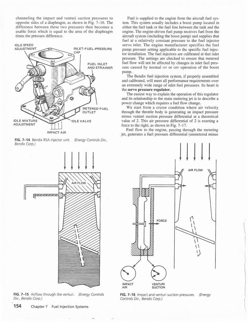
FIG. 7- 13 Continental fuel injection troubleshooting chart.
technician should make sure that other factors are not involved. A rough-running engine may have ignition problems which should be checked before dismantling the fuel control system.
The troubleshooting chart provided in Fig. 7-13 is a guide for determining what may be at fault. The items are arranged in order of the approximate ease of checking and not necessarily in the order of probability.
BENDIX RSA FUEL INJECTION SYSTEM
Principles of Operation
The Bendix RSA fuel injection system is a continuousflow system and is based on the same principles as those of the pressure-type carburetors described in Chap. 6. A pictorial view of the RSA injector unit is shown in Fig. 7-14.
Check mixture control to be in full IDLE CUTOFF.
Check auxiliary pump to be OFF. Clean nozzle assemblies (screens) or replace.
Replace manifold valve.
Bendix fuel injection systems are designed to meter fuel in direct ratio to the volume of air being consumed by the engine at a given time. This is accomplished by sensing venturi suction and impact air pressures in the throttle body. Opening or closing the throttle valve results in a change in the velocity of air passing across the impact tubes and through the venturi, as illustrated in Fig. 7-15. When the air velocity increases, the pressure at the impact tubes remains relatively constant depending on the inlet duct configuration, air filter location, etc. The pressure at the venturi throat decreases. This decrease creates a differential (impact minus suction) which is used over the entire range of operation of the Bendix fuel injection system as a measurement of the volume of air consumed.
All reciprocating engines operate most efficiently in a very narrow range of air-fuel (A/F) [or fuel-air (F/ A)] ratios. The Bendix injection system uses the measurement of air volume flow to generate a force which can be used to regulate the flow of fuel to the engine in proportion to the amount of air being consumed. This is accomplished by
Bendix RSA Fuel Injection System 153
channeling the impact and venturi suction pressures to opposite sides of a diaphragm, as shown in Fig. 7-16. The difference between these two pressures then becomes a usable force which is equal to the area of the diaphragm times the pressure difference.
IMPACT A IR
INLET- FUEL-PRESSUR E CAP
FUEL INLET AND STRAINER
FIG. 7-14 Bendix RSA injector unit. (Energy Controls Div., Bendix Corp.)
! ! 111
FIG. 7-15 Airflow through the venturi. (Energy Controls Div., Bendix Corp.)
154 Chapter 7 Fuel Injection Systems
Fuel is supplied to the engine from the aircraft fuel system. This system usually includes a boost pump located in either the fuel tank or the fuel line between the tank and the engine. The engine-driven fuel pump receives fuel from the aircraft system (including the boost pump) and supplies that fuel at a relatively constant pressure to the fuel injector servo inlet. The engine manufacturer specifies the fuel pump pressure setting applicable to the specific fuel injector installation. The fuel injectors are calibrated at that inlet pressure. The settings are checked to ensure that metered fuel flow will not be affected by changes in inlet fuel pressure caused by normal ON or OFF operation of the boost pump . .
The Bendix fuel injection system, if properly assembled and calibrated, will meet all performance requirements over an extremely wide range of inlet fuel pressures. Its heart is the servo pressure regulator.
The easiest way to explain the operation of this regulator and its relationship to the main metering jet is to describe a power change which requires a fuel flow change.
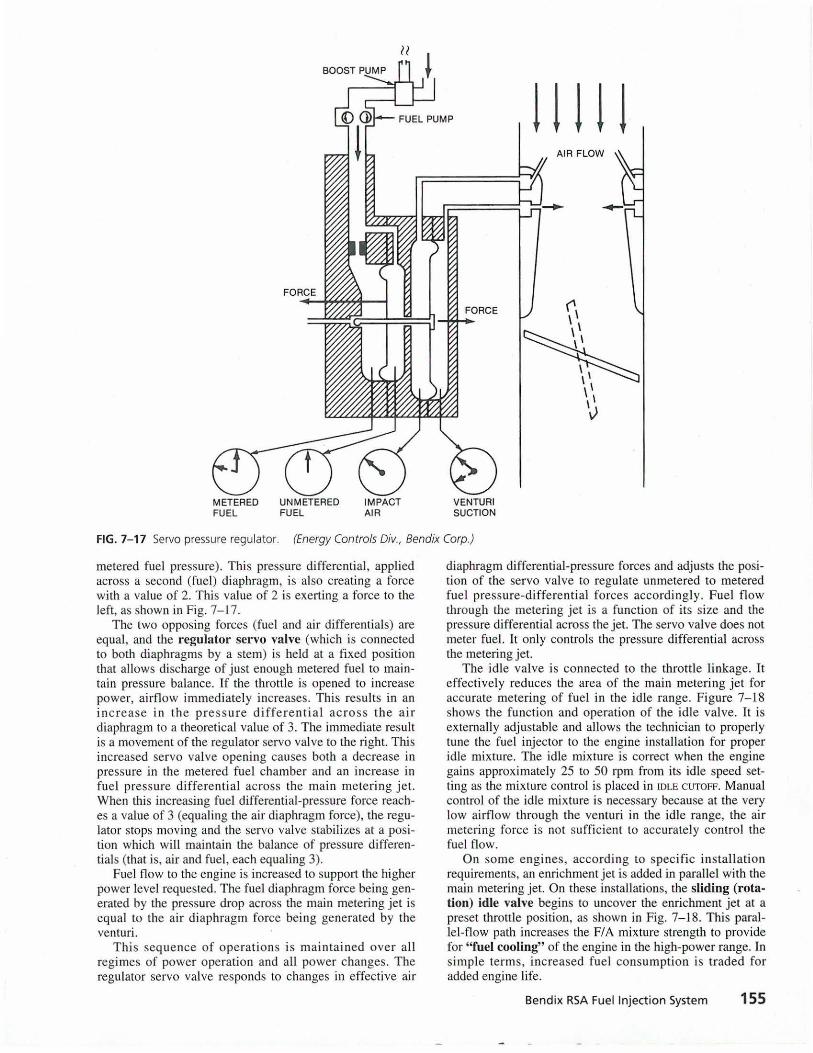
We start from a cruise condition where air velocity through the throttle body is generating an impact pressure minus venturi suction pressure differential at a theoretical value of 2. This air pressure differential of 2 is exerting a force to the right, as shown in Fig. 7-17.
Fuel flow to the engine, passi ng through the metering jet, generates a fuel pressure differential (unmetered minus
IMPACT AIR
FORCE
VENTURI SUCTION
1 ! j 1 ! AIR FLOW
FIG. 7-16 Impact and venturi suction pressures. (Energy Controls Div., Bendix Corp.)
METERED UN METERED FUEL FUEL
IMPACT AIR
VENTURI SUCTION
11111
FIG. 7-17 Servo pressure regulator. (Energy Controls Div., Bendix Corp.)
metered fuel pressure). This pressure differential, applied across a second (fuel) diaphragm, is also creating a force with a value of 2. This value of 2 is exerting a force to the left, as shown in Fig. 7-17 .
The two opposing forces (fuel and air differentials) are equal, and the regulator ser vo valve (which is connected to both diaphragms by a stem) is held at a fixed position that allows discharge of just enough metered fuel to maintain pressure balance. If the throttle is opened to increase power, airflow immediately increases. This results in an in crease i n the p ressure differenti al ac ross the ai r diaphragm to a theoretical value of 3. The immediate result is a movement of the regulator servo valve to the right. This increased servo valve opening causes both a decrease in pressure in the metered fuel chamber and an increase in fu el pressure differenti al across the main metering jet. When this increasing fuel differential-pressure force reaches a value of 3 (equaling the air diaphragm force), the regulator stops moving and the servo valve stabilizes at a position which will maintain the balance of pressure differentials (that is, air and fuel, each equaling 3).
Fuel flow to the engine is increased to support the higher power level requested. The fuel diaphragm force being generated by the pressure drop across the main metering jet is equal to the air diaphragm force being generated by the venturi.
T his seque nce of operations is maintained over all regimes of power operation and all power changes. The regulator servo valve responds to changes in effective air
diaphragm differential-pressure forces and adjusts the position of the servo valve to regulate unmetered to metered fuel pressure-differential forces accordingly. Fuel flow through the metering jet is a function of its s ize and the pressure differential across the jet. The servo valve does not meter fuel. It only controls the pressure differential across the metering jet.
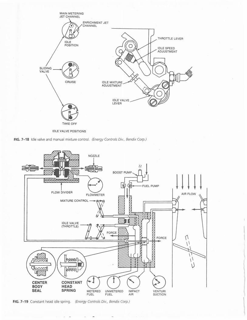
The idle valve is connected to the throttle linkage. It effectively reduces the area of the main metering jet for accurate metering of fuel in the idle range. Figure 7-18 shows the fu nction and operation of the idle valve. It is externally adjustable and allows the technician to properly tune the fuel injector to the engine installation for proper idle mixture. The idle mixture is correct when the engine gains approximately 25 to 50 rpm from its idle speed setting as the mixture control is placed in IDLE CUTOFF. Manual control of the idle mixture is necessary because at the very low airflow through the venturi in the idle range, the air metering force is not sufficient to accurately control the fuel flow.
On some engines, according to specific installation requirements, an enrichment jet is added in parallel with the main metering jet. On these installations, the sliding (rotation) idle valve begins to uncover the enrichment jet at a preset throttle position, as shown in Fig. 7- 18. This parallel-flow path increases the F/ A mixture strength to provide for " fuel cooling" of the engine in the high-power range. In si mple terms, increased fuel consumption is traded for added engine life.
Bendix RSA Fuel Injection System 155
MAIN METERING JET CHANNEL
SLIDING -©P. VALVE ;j
\
CRUISE
TAKE OFF
ENRICHMENT JET CHANNEL
IDLE VALVE POSITIONS
IDLE VALVE LEVER
FIG. 7- 18 Idle valve and manual mixture control. (Energy Controls Div., Bendix Corp.)
FLOW DIVIDER ~ FLOWMETER
METERED UNMETERED IMPACT FUEL FUEL AIR
FIG. 7- 19 Constant head idle spring. (Energy Controls Div., Bendix Corp.)
FORCE
VENTURI SUCTION
1111 ! AIR FLOW

The manual mixture control, shown in Fig. 7-18 as a sliding valve, can be used by the pilot to effectively reduce the size of the metering jet. With the servo pressure regulator functioning to maintain a differential pressure across the metering jet in proportion to the volume of airflow, the flow through the jet may be varied by changing its effective size. This gives the pilot the option of manually leaning the mixture for best cruise power or best SFC. It also provides the means to shut off fuel flow to the engine at engine shutdown.
The constant head idle spring augments the force of the air diaphragm in the idle range when the air pressure differential is not sufficient to open the servo valve. The idle spring shown in Fig. 7- 19 ensures that the regulator servo valve is open sufficiently to allow fuel being metered by the idle valve to flow out to the flow divider. As airflow increases above idle, the air diaphragm will begin to move to the right in response to increasing air pressure differential. It will compress the constant head idle spring until its retainer and guide contact the diaphragm plate. From this point onward, in terms of airflow, fuel flow, or power, the constant head idle spring assembly is a solid member moving with the air diaphragm and exerts no force of its own. The constant head spring is furnished in various strengths so that the overhaul technician can properly calibrate the injector for idle fuel flow and for the transition to servo regulator controlled fuel flow.
In most installations, the transition from idle to servo regulator controlled fuel flow has to be supplemented with a constant-effort spring, pictured in Fig. 7-20. This spring also assists the air diaphragm in moving smoothly from the low-airflow idle range to the higher-power range of opera-
tion. It also comes in a selection of strengths to be utilized by the overhaul technician for proper calibration of the unit.
The fuel section of the servo pressure regulator is separated from the air section by a center body seal assembly, as shown in Fig. 7-20. Leakage through the center body seal causes extre me ly rich operation and poor cutoff. Leakage of raw fuel out of the impact tubes may indicate possible seal leakage. Failure of this seal requires repair in an overhaul shop. The seal cannot be replaced in the field.
Automatic Mixture Control
The AMC adjusts the FIA ratio to compensate for the decreased air density as the aircraft climbs to altitude. Figure 7-21 shows the function and operation of the AMC and expands on the description of the manual mixture control and idle valves. The mixture control is shown in the FULL RICH position and with the idle valve fully open, as it would be at cruise power or above. In the cutaway view, the two rotating valve assemblies are spring-loaded together, back to back, with an 0-ring seal between them. Fuel flows through the mixture control valve, through the idle valve, and out to the regulator servo va lve. The inlet strainer is located underneath the fuel inlet fi tting and is installed spring end first, so the open end is mated to the inlet fitting. If the screen is blocked by contaminant material, inlet pressure will force the material away from the fitting, compressing the spring to allow fuel to bypass the screen if necessary. This screen filter is replaced at overhaul. There is no approved method of cleaning th is screen for reuse.
CONSTANT EFFORT SPRING
CENTER BODY SEAL
AIR DIAPHRAGM
FIG. 7-20 Constant-effort spring. (Energy Controls Div., Bendix Corp.)
Bendix RSA Fuel Injection System 157
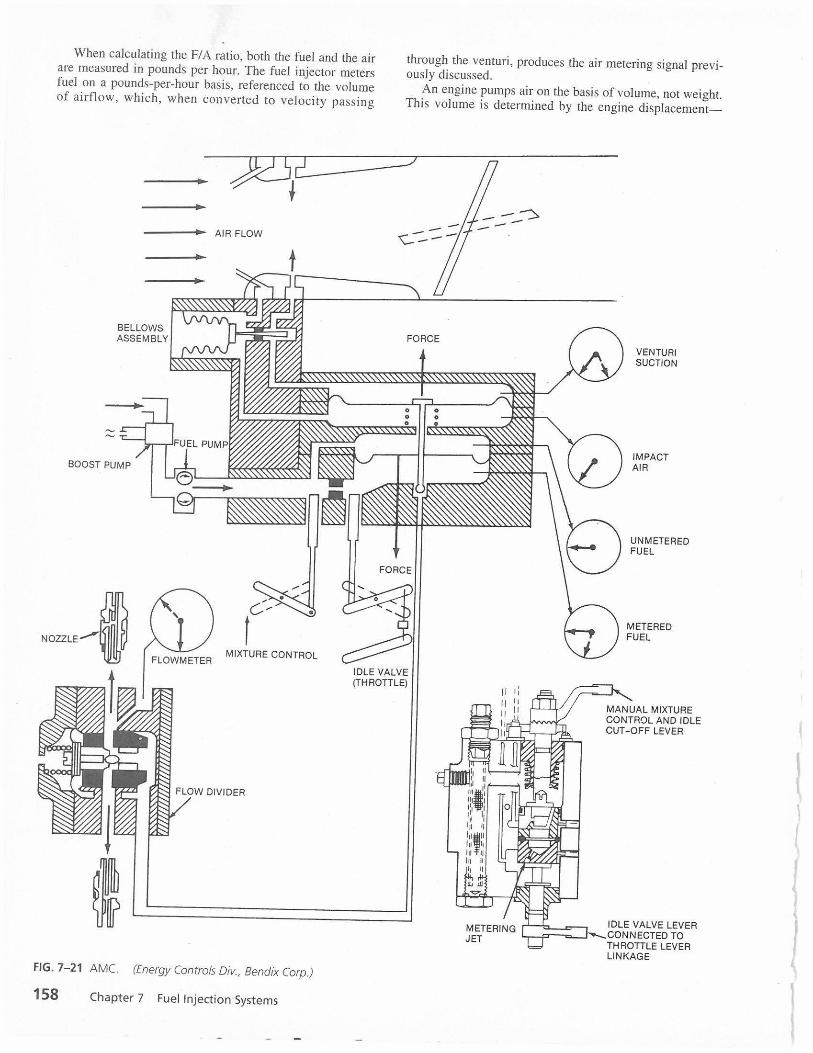
When calculating the FIA ratio, both the fuel and the air are measured in pounds per hour. The fuel injector meters fuel on a pounds-per-hour basis, referenced to the volume of ai rflow, which, when con verted to velocity passi ng
AIR FLOW
through the venturi , produces the air metering signal previously discussed.
An engine pumps air on the basis of volume, not weight. This volume is determined by the engine displacement-
FORCE
0 0 0 0
VENTURI SUCTION
~:s:ssss:~· ~·~~~
BOOST PUMP
FLOWMETER MIXTURE CONTROL
FIG. 7-21 AMC. (Energy Controls Div., Bendix Corp.)
158 Chapter 7 Fuel Injection Systems
IDLE VALVE (THROTTLE)
IMPACT AIR
UN METERED FUEL
METERED FUEL
IDLE VALVE LEVER L---=-=---.J--CONNECTED TO
THROTTLE LEVER LINKAGE 1
that is, 540 in3 per complete four-stroke cycle (intake, compress ion , powe r, and exhaust for all s ix cy linde rs). Therefore an I0-540 engine running at 2500 rpm would be consuming (pumping) air at a rate of
or
540 x 25
2°0 = 675,000 in 3/min [1 I m3/min]
675,000 = 390 ft 3/min [11 m3/min] 1728
390 x 0.0765 = 30 lb/min [13.6 kg/min]
30 lb/minx 60 min= 1800 lb/h [8 16 kg/h]
This would be equivalent to cruise power at sea level. An FIA ratio of 0.08 would result in a fuel flow rate of
1800 x 0.08 = 144 lb/h [65 kg/h]
As the aircraft climbs to altitude, the specific weight of air decreases from 0.0765 lb/ft3 [ 1.22 kg/m3] until, at 15,000 ft , air weighs only 0.0432 lb/ft3 [0.692 kg/m3]. The engine operating at 2500 rpm would sti ll be consuming 390 ft3/min [1 1 m3/min], resulting in an airflow rate of
390 x 0.0432 x 60 = 1011 lb/h [459 kg/h]
This 1011 -lb/h [459-kg/h] airflow will produce the same air metering s igna l across the venturi that 1800 lb/h [816 kg/h) did at sea level. This air metering signal will maintain the 144-lb/h [65-kg/h] fuel flow, which results in
144 = 0.142 FIA ratio
1011
Without an AMC, it would be necessary for the pilot to continually lean the mixture manuall y to maintain the desired 0.08 Fl A ratio. The AMC works independently of, and in parallel with, the manual mixture control by providing a variable orifice between the two air pressure signals (impact and suction) to modify the air metering s ignal force.
The AMC assembly consists of a contoured needle that is moved in and out of an orifice by a bellows assembly. This bellows reacts to changes in air pressure and temperature, increasing in length as pressure altitude increases. At ground level, the needle is positioned in the AMC orifice so that the orifice is closed, or nearly closed, to allow the maximum impact pressure on the impact pressure side of the air diaphragm.
When the ai rcraft flies at increased altitude, the AMC bellows elongates with the air pressure decrease and the needle is moved into its orifice. This increases the orifice opening between the impact air and venturi suction and allows impact air to bleed into the venturi suction channel. Thi s reduces the air meterin g force acros s the air diaphragm.
The needle is contoured so that regardless of altitude (or air density) the correct air metering s ignal is established across the air diaphragm to maintain a relatively constant FIA ratio as the air density changes with altitude.
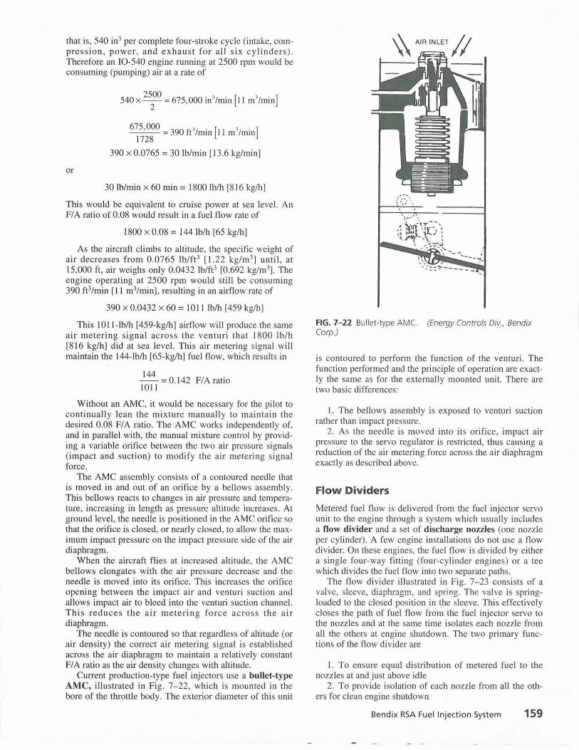
Cun-ent production-type fuel injectors use a bullet-type AMC, illustrated in Fig. 7-22, which is mounted in the bore of the throttle body. The exterior diameter of this unit
FIG. 7-22 Bullet-type AMC. (Energy Controls Div., Bendix Corp.)
is contoured to perform the function of the venturi. The function performed and the principle of operation are exactly the same as for the externally mounted unit. There are two basic differences:
l. The bellows assembly is exposed to venturi suction rather than impact pressure.
2. As the needle is moved into its orifice, impact air pressure to the servo regulator is restricted, thus causing a reduction of the air metering force across the ai r diaphragm exactly as described above.
Flow Dividers
Metered fuel flow is delivered from the fuel injector servo unit to the engine through a system which usually includes a flow divider and a set of discharge nozzles (one nozzle per cylinder). A few engine installations do not use a flow divider. On these engines, the fuel flow is divided by either a single four-way fitting (four-cylinder engines) or a tee which divides the fuel flow into two separate paths.
The flow divider illustrated in Fig. 7-23 consists of a valve, sleeve, diaphragm, and spring. The valve is springloaded to the closed position in the sleeve. This effectively closes the path of fuel flow from the fuel injector servo to the nozzles and at the same time isolates each nozzle from all the others at engine shutdown. The two primary functions of the flow divider are
l. To ensure equal distribution of metered fuel to the nozzles at and just above idle
2. To provide isolation of each nozzle from all the others for clean engine shutdown
Bendix RSA Fuel Injection System 159
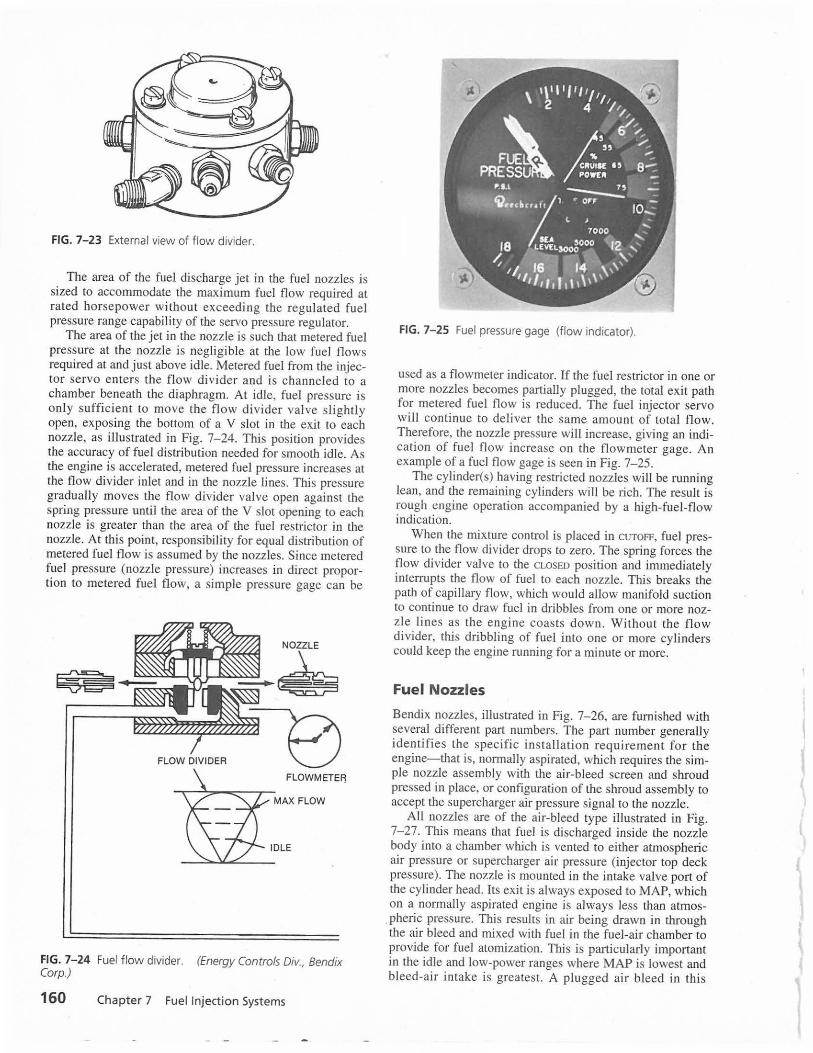
FIG. 7-23 External view of flow divider.
The area of the fuel discharge jet in the fuel nozzles is sized to accommodate the maximum fuel flow required at rated horsepower without exceeding the regulated fuel pressure range capability of the servo pressure regulator.
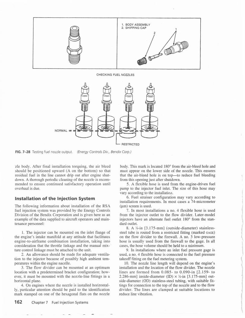
The area of the jet in the nozzle is such that metered fuel pressure at the nozzle is negligible at the low fuel ~~ws required at and just above idle. Metered fuel from the mJeCtor servo enters the fl ow divider and is channeled to a chamber beneath the diaphragm. At idle, fuel pressure is only sufficient to move the flow divider valve slightly open, exposing the bottom of a V slo~ in th~ .exit to ~ach nozzle, as illustrated in Fig. 7-24. This pos1t10n provides the accuracy of fuel distribution needed for smooth idle. As the engine is accelerated, metered fuel pressure increases at the flow divider inlet and in the nozzle lines. This pressure oradually moves the flow divider valve open against the ~pring pressure until the area of the V slot open~ng t~ each nozzle is greater than the area of the fuel restnctor 111 the nozzle. At this point, responsibility for equal distribution of metered fuel flow is assumed by the nozzles. Since metered fuel pressure (nozzle pressure) increases in direct proportion to metered fuel flow, a simple pressure gage can be
FLOW DIVIDER
FLOWMETEF!
MAX FLOW
IDLE
FIG. 7-24 Fuel flow divider. (Energy Controls Div., Bendix Corp.)
160 Chapter 7 Fuel Injection Systems
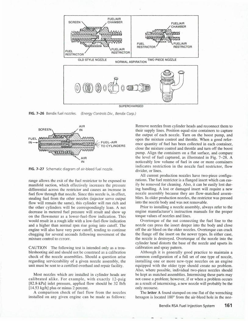
FIG. 7-25 Fuel pressure gage (flow indicator).
used as a flowmeter indicator. If the fuel restrictor in one or more nozzles becomes partially plugged, the total exit path for metered fuel flow is reduced. The fuel injector servo will continue to deliver the same amount of total flow. Therefore, the nozzle pressure will increase, giving an indication of fuel flow increase on the flowmeter gage. An example of a fuel flow gage is seen in Fig. 7-2.5 . .
The cylinder(s) having restricted nozzles will be runnmg lean, and the remaining cylinders wilt be iich. The result is rough t!ngine operation accompanied by a high-fuel-flow indication.
When the mixture control is placed in CUTOFF, fuel pressure to the flow divider drops to zero. The spring forces the flow divider valve to the CLOSED position and immediately interrupts the flow of fuel to each nozzle. Thi.s breaks ~he path of capillary flow, which would allow mamfold suction to continue to draw fuel in dribbles from one or more nozzle lines as the engine coasts down. Without the flow divider, this dribbling of fuel into one or more cylinders could keep the engine running for a minute or more.
Fuel Nozzles
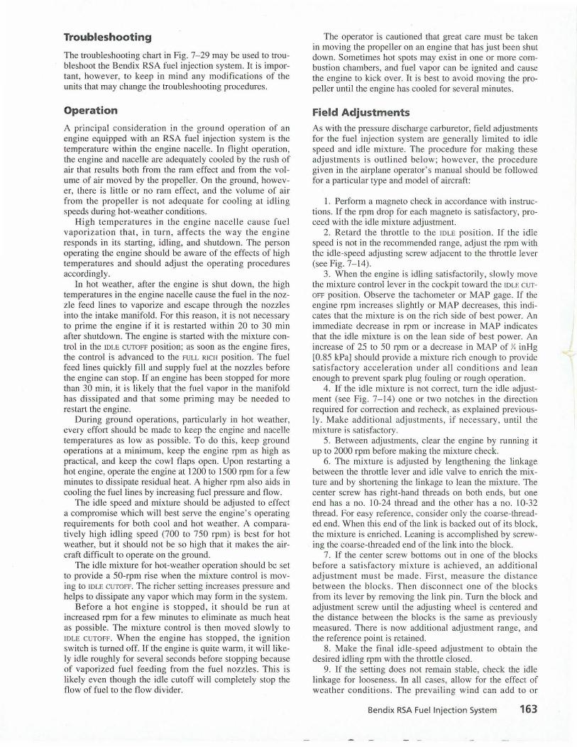
Bendix nozzles, illustrated in Fig. 7-26, are furnished with several different part numbers. The part number generally identifies the specific installation requirement for the engine-that is, normally aspirated, which requires the simple nozzle assembly with the air-bleed screen and shroud pressed in place, or configuration of the shroud assembly to accept the supercharger air pressure signal to the nozzle.
All nozzles are of the air-bleed type illustrated in Fig. 7-27. This means that fuel is discharged inside the nozzle body into a chamber which is vented to either atmospheric air pressure or supercharger air pressure (injector top deck pressure). The nozzle is mounted in the intake valve port. of the cylinder head. Its exit is always exposed to MAP, which on a normally aspirated engine is always less than atmospheric pressure. This results in air being drawn in through the air bleed and mixed with fuel in the fuel-air chamber to provide for fuel atomization. This is particularly important in the idle and low-power ranges where MAP is lowest and bleed-air intake is greatest. A plugged air bleed in this
FUEL RESTRICTOR
FU EU AIR CHAMBER
FUEL RESTRICTOR
OLD STYLE NOZZLE NORMAL ASPIRATION TWO PIECE NOZZLE
SUPERCHARGED
FIG. 7-26 Bendix fuel nozzles. (Energy Controls Div., Bendix Corp.)
FIG. 7-27 Schematic diagram of air-bleed fuel nozzle.
range allows the exit of the fuel restrictor to be exposed to manifold suction, which effectively increases the pressure differential across the restrictor and causes an increase in fuel flow through that nozzle. Since this nozzle is, in effect, stealing fuel from the other nozzles (injector servo output flow will remain the same), this cylinder will run rich and the other cyl inders will be correspondingly lean. A net decrease in metered fuel pressure will result and show up on the fl owmeter as a lower-fuel-flow indication. This would result in a rough idle with a low-fuel-flow indication and a higher than normal rpm rise going into cutoff. The engine will also have very poor cutoff, tending to continue chugging for several seconds following movement of the mixture control to CUTOFF.
CAUTION The following test is intended only as a troubleshooting aid and shou ld not be construed as a calibration check of the nozzle assemblies. Should a question arise regarding serviceability of a given nozzle assembly, the unit must be sent to a certified overhaul and repair facility.
Most nozzles which are installed in cylinder heads are calibrated alike. For examp le, with exactly 12-psig (82.8-kPa] inlet pressure, applied flow should be 32 Jb/h [14.53 kg/h) plus or minus 2 percent.
A comparison check of fue l flow from the nozzles in stall ed on any given engine can be made as follows:
Remove nozzles from cylinder heads and reconnect them to their supply lines. Position equal-size containers to capture the output of each nozzle. Turn on the boost pump, and open the mixture control and throttle. When a good reference quantity of fuel has been collected in each container, close the mixture control and throttle and turn off the boost pump. Align the containers on a flat surface, and compare the level of fuel captured, as illustrated in Fig. 7-28. A noticeably low volume of fuel in one or more containers indicates restriction in the nozzle fuel restrictor, flow divider, or lines.
All current production nozzles have two-piece configurations. The fuel restrictor is a flanged insert which can easily be removed for cleaning. Also, it can be easily lost during handling. A Lost or damaged insert will requi re a new nozzle assembly because they are flow-matched assemblies. Jn older production nozzles, the restrictor was pressed into the nozzle body and was not removable.
Prior to installing a nozzle assembly, always refer to the engine manufacturer's instruction manuals for the proper torque values of nozzles and lines.
Overtorq ue of the nut connecting the fuel l ine to the nozzle can press the inse1t deeper into the body and close off the air bleed on the older nozzles. Overtorque can crack the flange off the insert on the newer types. In either case, the nozzle is destroyed. Overtorque of the nozzle into the cylinder head distorts the base of the nozzle and upsets its calibration and spray pattern.
Although it is generally good practice to maintain a common configuration of a full set of one type of nozzle, installing one or more new-type nozzles on an engine equipped with the older type should create no problem. Also, where possible, individual two-piece nozzles should be kept as matched assemblies. Intermixing these parts may not cause a problem; however, if or when a problem occurs as a result of intermixing, a new nozzle will probably be the only recourse.
The letter A found stamped on one flat of the wrenching hexagon is located 180° from the air-bleed hole in the noz-
Bend ix RSA Fuel Injection System 161
1. BODY ASSEMBLY 2. SHIPPING CAP
CHECKING FUEL NOZZLES
NORMAL =
FIG. 7- 28 Testing fuel nozzle output. (Energy Controls Div., Bendix Corp.)
zle body. After final installation torquing, the air bleed should be positioned upward (A on the bottom) so that residual fuel in the line cannot drip out after engine shutdown. A thorough periodic cleaning of the nozzle is recommended to ensure continued satisfactory operation until overhaul is due.
Installation of the Injection System
The following information about installation of the RSA fuel injection system was provided by the Energy Controls Division of the Bendix Corporation and is given here as an example of the data supplied to aircraft operators and maintenance personnel:
l. The injector can be mounted on the inlet flange of the engine's intake manifold at any attitude that facilitates engine-to-airframe combination installation, taking into consideration that the throttle linkage and the manual mixture control linkage must be attached to the unit.
2. An allowance should be made for adequate ventilation to the injector because of possibly high ambient temperatures within the engine nacelle.
3. The flow divider can be mounted at an optimum location with a predetermined bracket configuration; however, it must be mounted with the nozzle-line fittings in a horizontal plane.
4. On engines where the nozzle is installed horizontally, particular attention should be paid to the identification mark stamped on one of the hexagonal flats on the nozzle
162 Chapter 7 Fuel Injection Systems
body. This mark is located 180° from the air-bleed hole and must appear on the lower side of the nozzle. This ensures that the ai r-bleed hole is on top-to reduce fuel bleeding from this opening just after shutdown.
5. A flexible hose is used from the engine-driven fuel pump to the injector fuel inlet. The size of this hose may vary according to the installation.
6. Fuel strainer configuration may vary according to installation requirements. In most cases a 74-micrometer (µm ) screen is used.
7. In most installations a no. 4 flexible hose is used from the injector outlet to the flow divider. Later-model injectors have an alternate fuel outlet 180° from the standard outlet.
8. A Ya-in [3.175-mm] (outside-diameter) stain lesssteel tube is routed from a restricted fitting (marked GAGE)
on the flow divider to the firewal l. A no. 3 low-pressure hose is usually used from the firewall to the gage. In all cases, the hose volume should be held to a minimum.
9. In installations where an inlet fuel pressure gage is used, a no. 4 flexible hose is connected to the fuel pressure takeoff fitting on the fuel metering system.
10. The nozzle line length will depend on the engine's installation and the location of the flow divider. The nozzle Jines are formed from 0.085 - to 0.090- in [2. 159- to 2.286-mm] inside-diameter (ID) x Ys-in [3. 175-mm] outside-diameter (OD) stainless-steel tubing, with suitable fittings for connection to the top of the nozzle and to the flow divider. The lines are clamped at suitable locations to reduce line vibration.
Troubleshooting
The troubleshooting chart in Fig. 7-29 may be used to troubleshoot the Bendix RSA fuel injection system. It is important, however, to keep in mind any modifications of the units that may change the troubleshooting procedures.
Operation
A principal consideration in the ground operation of an engine equipped with an RSA fuel injection system is the temperature within the engine nacelle. In flight operation, the engine and nacelle are adequately cooled by the rush of air that results both from the ram effect and from the volume of air moved by the propeller. On the ground, however, there is little or no ram effect, and the volume of air from the propeller is not adequate for cooling at idling speeds during hot-weather conditions.
Hi gh temperatures in the engine nacelle cause fu el vapori zation that, in turn, affects the way the engine responds in its starting, idling, and shutdown. The person operating the engine should be aware of the effects of high temperatures and should adjust the operating procedures accordingly.
ln hot weather, after the engine is shut down, the high temperatures in the engine nacelle cause the fuel in the nozzle feed lines to vaporize and escape through the nozzles into the intake manifold. For this reason, it is not necessary to prime the engine if it is restarted within 20 to 30 min after shutdown. The engine is started with the mixture control in the IDLE CUTOFF position; as soon as the engine fires, the control is advanced to the FULL RICH position. The fuel feed lines quickly fill and supply fuel at the nozzles before the engine can stop. If an engine has been stopped for more than 30 min, it is likely that the fuel vapor in the manifold has dissipated and that some priming may be needed to restart the engine.
During ground operations, particularly in hot weather, every effort should be made to keep the engine and nacelle temperatures as low as possible. To do this, keep ground operations at a minimum, keep the engine rpm as high as practical, and keep the cowl flaps open. Upon restarting a hot engine, operate the engine at 1200 to 1500 rpm for a few minutes to dissipate residual heat. A higher rpm also aids in cooling the fuel lines by increasing fuel pressure and flow.
The idle speed and mixture should be adjusted to effect a compromise which will best serve the engine's operating requirements for both cool and hot weather. A comparatively high idling speed (700 to 750 rpm) is best for hot weather, but it should not be so high that it makes the aircraft di fficult to operate on the ground.
The id le mixture for hot-weather operation should be set to provide a 50-rpm rise when the mixture control is moving to IDLE CUTOFF. The richer setting increases pressure and helps to dissipate any vapor which may form in the system.
Before a ho t e ngine is stopped, it should be run at increased rpm for a few minutes to eliminate as much heat as possible. The mixture control is then moved slowly to IDLE CUTOFF. When the engine has stopped, the ignition switch is turned off. If the engine is quite warm, it will likely idle roughly for several seconds before stoppi ng because of vaporized fuel feeding from the fuel nozzles. This is likely even though the idle cutoff wil l completely stop the flow of fuel to the flow divider.
The operator is cautioned that great care must be taken in moving the propeller on an engi ne that has just been shut down. Sometimes hot spots may exist in one or more combustion chambers, and fuel vapor can be ignited and cause the engine to kick over. It is best to avoid moving the propeller until the engine has cooled for several minutes.
Field Adjustments As with the pressure discharge carburetor, field adjustments for the fuel injection system are generally limited to idle speed and idle m ixture. The procedure for making these adju stments is outli ned below; however, the procedure given in the airplane operator's manual should be followed for a particular type and model of aircraft:
1. Perform a magneto check in accordance with instructions. If the rpm drop for each magneto is satisfactory, proceed with the idle mixture adjustment.
2. Retard the throttle to the IDLE position. If the idle speed is not in the recommended range, adjust the rpm with the idle-speed adjusting screw adjacent to the throttle lever (see Fig. 7-14).
3. When the engine is idling satisfactorily, slowly move the mixture control lever in the cockpit toward the IDLE CUT
OFF position. Observe the tachometer or MAP gage. If the engine rpm increases slightly or MAP decreases, this indicates that the mixture is on the rich side of best power. An immediate decrease in rpm or increase in MAP indicates that the idle mixture is on the lean side of best power. An increase of 25 to 50 rpm or a decrease in MAP of Y. inHg [0.85 kPa) should provide a mixture rich enough to provide satisfactory acceleration under all conditions and lean enough to prevent spark plug fouling or rough operation.
4. If the idle mixture is not correct, turn the idle adjustment (see Fig. 7-14) one or two notches in the direction required for correction and recheck, as explained previously. Make additional adjustments, if necessary, until the mixture is satisfactory.
5. Between adjustments, clear the engine by running it up to 2000 rpm before making the mixture check.
6. The mixture is adjusted by lengthen ing the linkage between the throttle lever and idle valve to enrich the mixture and by shortening the li nkage to lean the mixture. The center screw has right-hand threads on both ends, but one end has a no. I 0-24 thread and the other has a no. 10-32 thread. For easy reference, consider only the coarse-threaded end. When this end of the link is backed out of its block, the mixture is enriched. Leaning is accompl ished by screwing the coarse-threaded end of the link into the block.
7. If the center screw bottoms out in one of the blocks before a satisfactory mixture is achieved, an additional adjustment mus t be made. First, measure the distance between the blocks. Then disconnect one of the blocks from its lever by removing the link pin. Turn the block and adjustment screw until the adjusting wheel is centered and the d istance between the blocks is the same as previously measured. There is now additional adjustment range, and the reference point is retained.
8 . Make the final idle-speed adjustment to obtain the desired idling rpm with the throttle closed.
9. If the setting does not remain stable, check the idle li nkage for looseness. In all cases, allow for the effect of weather cond itions . The prevailing wind can add to or
Bendix RSA Fuel Injection System 163
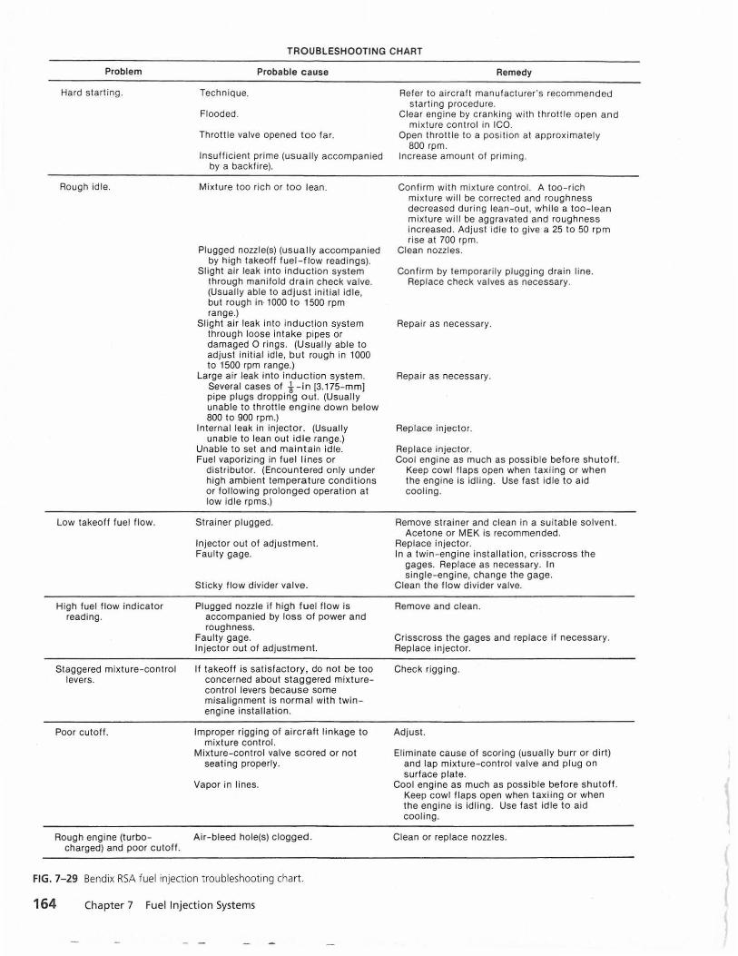
TROUBLESHOOTING CHART
Problem
Hard starting.
Rough idle.
Low takeoff fuel flow.
High fuel flow indicator reading.
Staggered mixture-control levers.
Poor cutoff.
Rough engine (turbocharged) and poor cutoff.
Probable cause
Technique.
Flooded.
Throttle valve opened too far.
Insufficient prime (usually accompanied by a backfire).
Mixture too rich or too lean.
Plugged nozzle(s) (usua lly accompanied by high takeoff fuel-flow readings).
Slight air leak into induction system through manifold drain check valve. (Usually able to adjust initial idle, but rough in· 1000 to 1500 rpm range.)
Slight air leak into induction system through loose intake pipes or damaged 0 rings. (Usually able to adjust initial idle, but rough in 1000 to 1500 rpm range.)
Large air leak into induction system. Several cases of i-in [3.175-mm) pipe plugs dropping out. (Usually unable to throttle engine down below 800 to 900 rpm.)
Internal leak in injector. (Usually unable to lean out idle range.)
Unable to set and maintain idle. Fuel vaporizing in fuel li nes or
distributor. (Encountered only under high ambient temperature conditions or following prolonged operation at low idle rpms.)
Strainer plugged.
Injector out of adjustment. Faulty gage.
Sticky flow divider valve.
Plugged nozzle if high fuel flow is accompanied by loss of power and roughness.
Faulty gage. Injector out of adjustment.
If takeoff is satisfactory, do not be too concerned about staggered mixturecontrol levers because some misalignment is normal with twin engine installation.
Improper rigging of aircraft linkage to mixture cont rol.
Mixture-control valve scored or not seating properly.
Vapor in lines.
Air-bleed hole(s) clogged.
FIG. 7- 29 Bendix RSA fuel injection troubleshooting chart.
164 Chapter 7 Fuel Injection Systems
Remedy
Refer to aircraft manufacturer's recommended starting procedure.
Clear engine by cranking with throttle open and mixture control in ICO.
Open throttle to a position at approximately 800 rpm.
Increase amount of priming.
Confirm with mixture control. A too-rich mixture will be corrected and roughness decreased during lean-out, while a too-lean mixture will be aggravated and roughness increased. Adjust idle to give a 25 to 50 rpm rise at 700 rpm.
Clean nozzles.
Confirm by temporarily plugging drain line. Replace check valves as necessary.
Repair as necessary.
Repair as necessary.
Replace injector.
Rep lace injector. Cool engine as much as possible before shutoff.
Keep cowl flaps open when taxiing or when the engine is idling. Use fast idle to aid cooling.
Remove strainer and clean in a suitable solvent. Acetone o r MEK is recommended.
Replace injector. In a twin - engine installation, crisscross the
gages. Replace as necessary. In single-engine, change the gage.
Clean the flow divider valve.
Remove and clean.
Crisscross the gages and replace if necessary. Replace injector.
Check rigging.
Adjust.
Eliminate cause of scoring (usually burr or dirt) and lap mixture-control valve and plug on surface plate.
Cool engine as much as possible before shutoff. Keep cowl flaps open when taxiing or when the engine is idling. Use fast idle to aid cooling.
Clean or replace nozzles.
reduce the propeller load and affect the engine rpm. During the idle mixture and rpm checks, the airplane should be placed crosswind.
Inspection and Maintenance
When a new injector unit is installed, the injector inlet strainer should be removed and cleaned after 25 h of operation. Thereafter, the strainer should be cleaned at each 50-h inspection.
If an aircraft engine is equipped with a fuel injector that includes an AMC, the operator should be alert for signs of problems with the unit. Dirt can build up on the needle and cause rich operation and possible sticking of the needle, with resultant loss of altitude compensation. The following instructions are given for cleaning the unit:
l. Carefully remove the AMC unit. If the gasket is damaged, replace it with a new gasket with the appropriate Bendix part number.
2. Remove the Y,6-24 plug and immerse the unit in clean naphtha or other approved petroleum solvent. Invert the unit so that it will fill completely with the solvent. Exercise the AMC needle with a hardwood or plastic rod to facil itate cleaning. Shake the unit vigorously while allowing the solvent to drain. Repeat several times to wash out all traces of contaminants.
3. Drain the unit, and allow the solvent to evaporate completely. Do not dry with compressed air.
4. Replace the plug, and install the unit on the injector. Torqu e to 50 to 60 po und inches ( lb•in) [5.65 to 6.78 Newton-meters (N•m)].
The injector should be lubricated in accordance with the approved lubrication chart for the particular installation. The clevis pins used in connection with the throttle and the manual mixture control should be checked for freedom of movement and lubricated if necessary.
Lubricate the throttle shaft bushings by placing a drop of engine oil on each end of the throttle shaft so that the oil can work into the bushings.
Use care in cleaning and oiling the air fi lter element. If the element is replaced with excessive oil clinging to it, some of the oil wi ll be drawn into the injector and will settle on the venturi. This can greatly affect the metering characteristics of the injector.
QUESTIONS ·
1. What is meant by "fuel injection"? 2. List the advantages of a fuel injection system. 3. What are the four basic units of the Continental
continuous-flow fuel injection system? 4. How many fuel control units are included in the
fuel control assembly? What are they? 5. At what locations on the engine are the fuel dis
charge nozzles installed? 6. Describe the construction of a fuel discharge
nozzle for the Continental fuel injection system. 7. What specia l featu re is required for the fuel dis
charge nozzles installed on a turbocharged engine? 8. Explain the operation of the altitude compensat
ing va lve. 9. How wou ld you adjust the idle speed for the
Continental fuel injection system? 10. How would you check the idle mixture for the
Continental fuel injection system? 11 . What unit is considered the heart of the Bendix
RSA fuel injection system. 12. What means are provided in the RSA system to
provide for adequate fuel flow at idling engine speeds? 13. What is the purpose of the AMC on the Bendix
RSA fuel injection system? 14. Describe the operation of the AMC on the RSA
fuel injector. 15. Describe the operation of the flow divider. 16. What factors determine the size of the calibrated
jet in the fuel nozzle? 17. What is meant when a fuel nozzle is classified as
an air-bleed type 7
18. In what position must the flow divider valve be installed on the RSA system?
19. Why must horizontally installed fuel nozzles be installed with the identification mark on the lower side?
20. What methods are employed to minimize engine heat during ground operation?
21 . What causes a warm engine to continue to idle for a few seconds after the mixture control is placed in IDLE CUTOFF?
22. List the items that are generally considered field adjustable on the RSA system.
23. Describe the procedure for checking the idle mixture for an RSA fuel injection system.
Review Questions 165

t I
( I 1
' l
' (
l (
•