fuel injection and spray research using x-ray diagnostics · fuel injection and spray research...
TRANSCRIPT

Fuel Injection and Spray Research Using X-Ray Diagnostics
Project ID ACE10
Christopher Powell
Argonne National Laboratory
VT Annual Merit Review 18 June 2014
Team Leaders: Gurpreet Singh, Ken Howden, Leo Breton This presentation does not contain any proprietary, confidential, or
otherwise restricted information
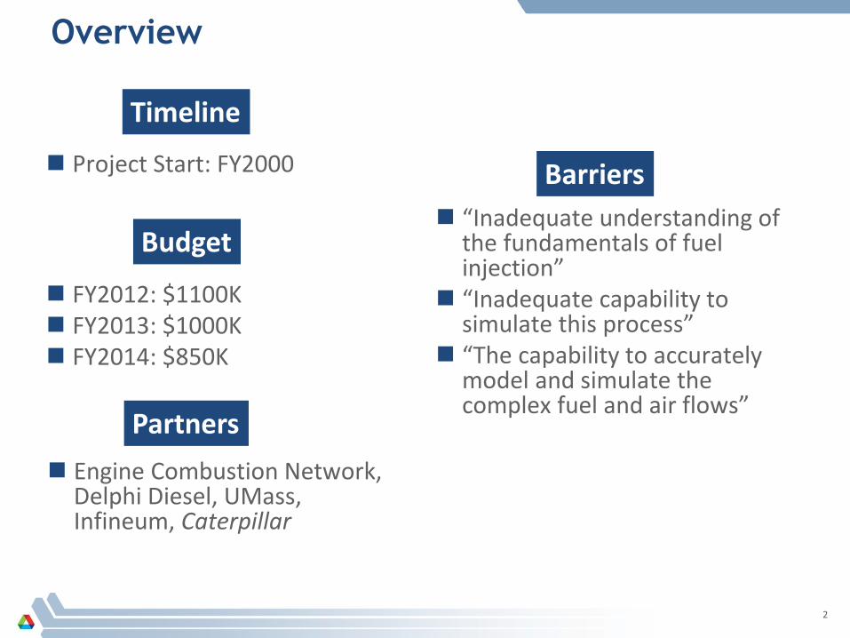
Overview
2
Timeline
Budget
Barriers
Partners
FY2012: $1100K FY2013: $1000K FY2014: $850K
Engine Combustion Network, Delphi Diesel, UMass, Infineum, Caterpillar
“Inadequate understanding of the fundamentals of fuel injection”
“Inadequate capability to simulate this process”
“The capability to accurately model and simulate the complex fuel and air flows”
Project Start: FY2000

Relevance and Objectives of this Research
3
■ Improve the fundamental understanding of fuel injection and sprays
■ Assist in development of improved spray models using our unique spray diagnostics
Understanding of fuel injection is a significant barrier to improving
efficiency and emissions

Milestones, FY2014
4
Q1 FY2014: Measurements of Delphi Diesel injectors Q2 FY2014: Measurements of ECN Multi-Hole Diesel: “Spray B” Q3 FY2014: Measurements of ECN GDI Injectors: “Spray G” Q4 FY2014: Deliver analysis of measurements to Delphi
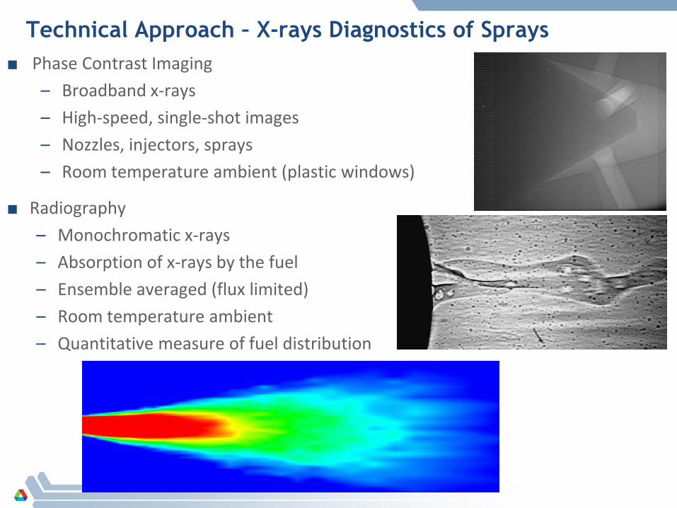
Technical Approach – X-rays Diagnostics of Sprays ■ Phase Contrast Imaging
– Broadband x-rays – High-speed, single-shot images – Nozzles, injectors, sprays – Room temperature ambient (plastic windows)
5
■ Radiography – Monochromatic x-rays – Absorption of x-rays by the fuel – Ensemble averaged (flux limited) – Room temperature ambient – Quantitative measure of fuel distribution
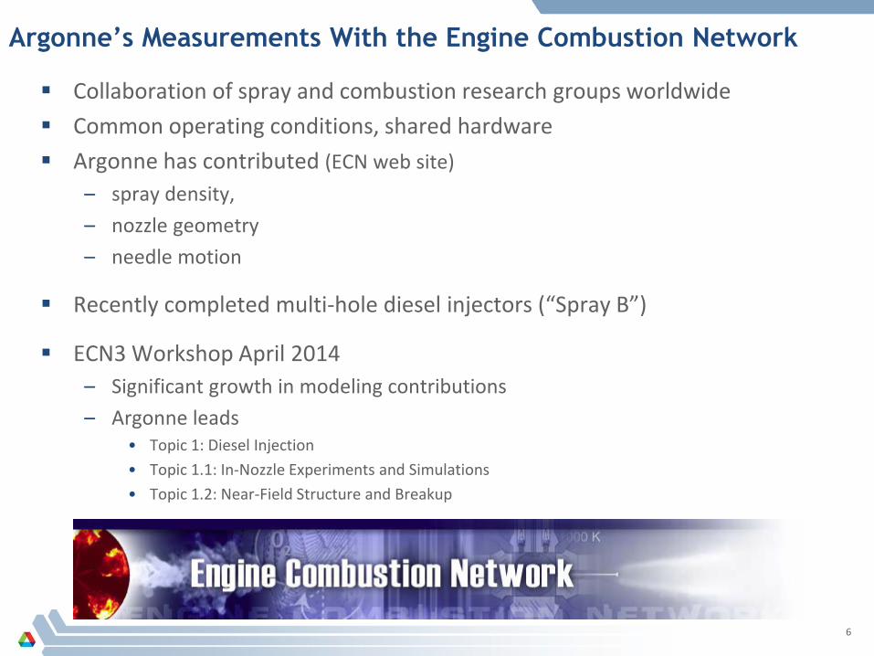
Argonne’s Measurements With the Engine Combustion Network
Collaboration of spray and combustion research groups worldwide Common operating conditions, shared hardware Argonne has contributed (ECN web site)
– spray density, – nozzle geometry – needle motion
Recently completed multi-hole diesel injectors (“Spray B”)
ECN3 Workshop April 2014 – Significant growth in modeling contributions – Argonne leads
• Topic 1: Diesel Injection • Topic 1.1: In-Nozzle Experiments and Simulations • Topic 1.2: Near-Field Structure and Breakup
6

Argonne Contributions to ECN in FY2014
7
Pickett et al. SAE 2014-01-1412
Comparison with Sandia Spray Imaging Calculate optical thickness from Argonne’s
measurements Compares well to optical measurements Proposes a unified definition of “spray boundary”
Needle Motion Fuel Density
Used by Argonne, CMT, UMass, IFPen, Aachen, Sandia, for internal
flow simulations
Used by validation of near–nozzle breakup simulations by Argonne, Sandia, CMT,
UMass, IFPen
0 4 8 12 16 20-1.0
-0.5
0.0
0.5
1.0
Axial Position (mm)
Fuel Density (µg/mm2)
0.0005.00010.0015.0020.0025.0030.0035.0040.0045.0050.00
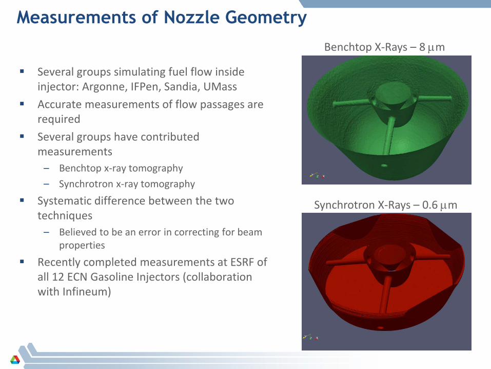
Measurements of Nozzle Geometry
Several groups simulating fuel flow inside injector: Argonne, IFPen, Sandia, UMass
Accurate measurements of flow passages are required
Several groups have contributed measurements
– Benchtop x-ray tomography – Synchrotron x-ray tomography
Systematic difference between the two techniques
– Believed to be an error in correcting for beam properties
Recently completed measurements at ESRF of all 12 ECN Gasoline Injectors (collaboration with Infineum)
Benchtop X-Rays – 8 µm
Synchrotron X-Rays – 0.6 µm
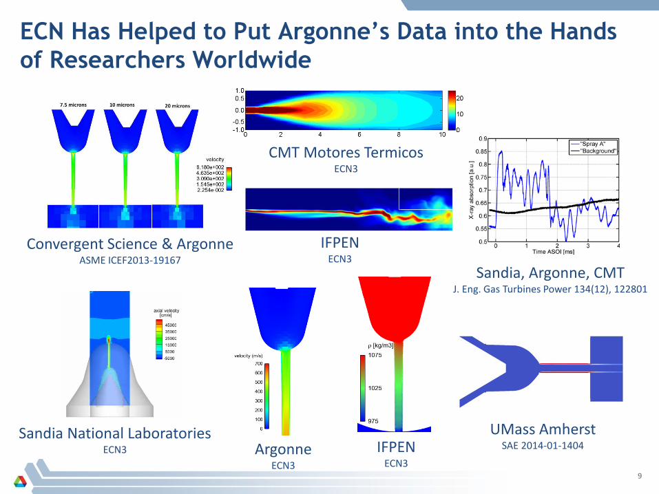
ECN Has Helped to Put Argonne’s Data into the Hands of Researchers Worldwide
9
Convergent Science & Argonne ASME ICEF2013-19167
Sandia, Argonne, CMT J. Eng. Gas Turbines Power 134(12), 122801
UMass Amherst SAE 2014-01-1404
Sandia National Laboratories ECN3 Argonne
ECN3 IFPEN
ECN3
CMT Motores Termicos ECN3
IFPEN ECN3
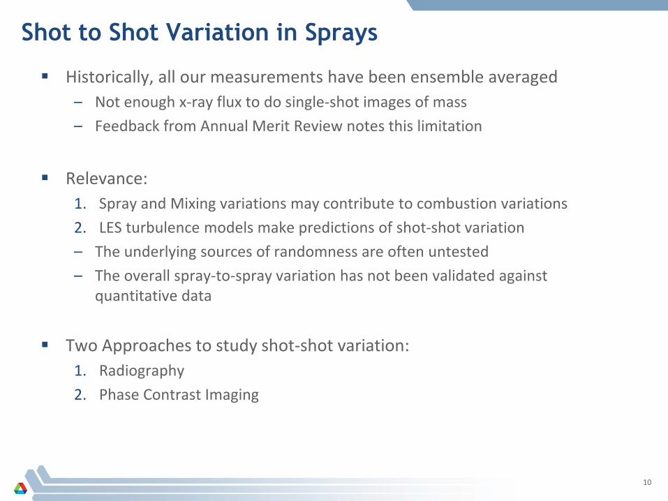
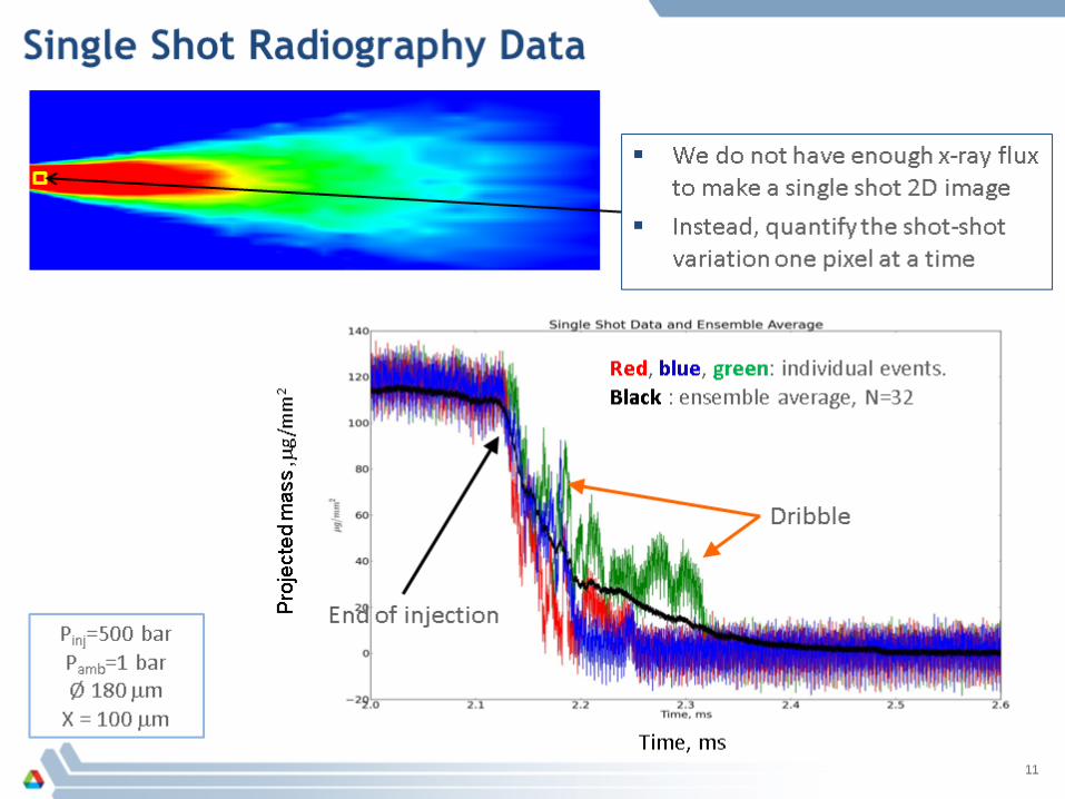
Shot to Shot Variation in Sprays
Historically, all our measurements have been ensemble averaged – Not enough x-ray flux to do single-shot images of mass – Feedback from Annual Merit Review notes this limitation
Relevance:
1. Spray and Mixing variations may contribute to combustion variations 2. LES turbulence models make predictions of shot-shot variation – The underlying sources of randomness are often untested – The overall spray-to-spray variation has not been validated against
quantitative data
Two Approaches to study shot-shot variation: 1. Radiography 2. Phase Contrast Imaging
10

Quantifying the Shot-to-Shot Variations
12
SOI Variation (timing)
EOI Variation
Steady-State Variation
At each position in the spray, we measure of standard deviation as a function of time
Spike in fluctuations at beginning of event is due to timing During steady-state, largest nozzle nozzle has highest variation End of injection dribble is highly variable, increases with orifice size. This can be used as a metric to quantify variations from different conditions,
injectors
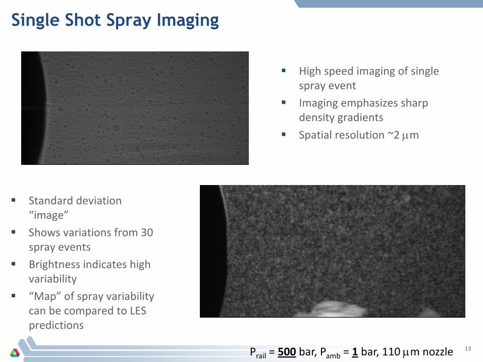
Single Shot Spray Imaging
13 Prail = 500 bar, Pamb = 1 bar, 110 µm nozzle
High speed imaging of single spray event
Imaging emphasizes sharp density gradients
Spatial resolution ~2 µm
Standard deviation “image”
Shows variations from 30 spray events
Brightness indicates high variability
“Map” of spray variability can be compared to LES predictions

Measurements and Simulation of Cavitation
Duke et al. SAE 2014-01-1404
In 2013 we demonstrated the new capability to measure cavitation in both plastic and steel nozzles
Modeling collaboration with UMass-Amherst
LES, Homogeneous Relaxation Model – 12M cells, Incompressible & Compressible
Argonne provides computational time Fixes and improvements to Schmidt’s
HRMFoam model - GM Argonne HPC group optimized
OpenFOAM to improve scalability on hundreds of processors – 17% faster
Cavitation measurements also used by Convergent Science, Argonne
Cavitation in Diesel Nozzle
Com
pres
sibl
e In
com
pres
sibl
e Predicted Vapor Fraction
Mea
sure
men
t

Bubbles in the Sac After End of Injection
15
Last year, showed that bubbles are pulled into the sac after the end of injection
Used a momentum argument to explain.
Battistoni & Som, Argonne
Simulations (same geometry and conditions) predict cavitation as the needle closes.
Cavitation bubbles collapse, sac pressure decreases, gas is pulled in.
Bubbles will expand as cylinder pressure decreases. Fuel will be pushed into cold engine (Musculus “late dribble”)
Additional simulations ongoing Gas in sac may affect SOI transient Simulations with empty sac are encouraged

Development of a New Diagnostic: X-ray Small Angle Scattering
Droplet size is a critical parameter for sprays Little is known about spray structure in near-
nozzle region Small angle x-ray scattering can measure
Sauter Mean Diameter in dense environments. (diameter of a sphere with the same volume/surface area ratio)
Size dramatically decreases within the first few mm of the nozzle
Good agreement with KH model predictions. New measurements:
– ECN Spray A – smaller nozzle, more volatile fuel – Multi-hole nozzles
Another constraint on spray simulations: Quantitative measurements of near-nozzle spray breakup
16
Simulations by S. Som, Argonne
0 5 10 15 200
10
20
30
40
50
500 bar, 5 bar 500 bar, 5 bar 500 bar, 10 bar 500 bar, 10 bar 1500 bar, 5 bar 1500 bar, 5 bar
Saut
er M
ean
Diam
eter
(µm
)
Distance From Nozzle (mm)
ECN Spray A
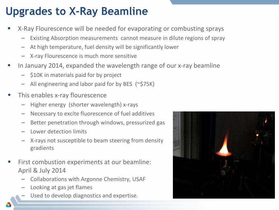
Upgrades to X-Ray Beamline X-Ray Flourescence will be needed for evaporating or combusting sprays
– Existing Absorption measurements cannot measure in dilute regions of spray – At high temperature, fuel density will be significantly lower – X-ray Flourescence is much more sensitive
In January 2014, expanded the wavelength range of our x-ray beamline – $10K in materials paid for by project – All engineering and labor paid for by BES (~$75K)
This enables x-ray flourescence – Higher energy (shorter wavelength) x-rays – Necessary to excite fluorescence of fuel additives – Better penetration through windows, pressurized gas – Lower detection limits – X-rays not susceptible to beam steering from density
gradients
First combustion experiments at our beamline: April & July 2014
– Collaborations with Argonne Chemistry, USAF – Looking at gas jet flames – Used to develop diagnostics and expertise.

Responses to FY2013 Reviewers’ Comments
18
“limited to room-temperature conditions ” “evaporation effects difficult to assess ”
Last year we reported successful test of high P,T x-ray windows New capabilities for x-ray flourescence Proof-of-concept experiments being planned: flash boiling at room temperature
“only producing ensemble-average data”
New effort this year to develop single-shot capability Hope to use for validation of LES predictions
“engagement with fuel-system suppliers would be useful ” “more collaborations with the industry fuel-injector suppliers”
CRADA with Delphi Diesel New WFO contract with Caterpillar

Collaborations DOE Advanced Engine Combustion Working Group
– All results presented at these meetings – Often results in new collaborations
Engine Combustion Network – Our data is integral for validation of internal flow simulaitions – Unique for validation of near-nozzle breakup models
Collaboration with Sibendu Som’s group – Cavitation – Bubbles in sac – Needle motion effects – ECN
University of Massachusetts Amherst – Cavitation – Improvements to HRM Model
International Energy Agency Combustion Agreement – Simulations of Natural Gas Jet measurements by Aalto Univerity
Industrial Contracts: – Delphi Diesel – Caterpillar

Remaining Challenges and Barriers: High Temperature Sprays
1. X-ray windows 2. Low fuel density 3. How to generate the temperature?
X-Ray Windows 1. X-ray transparent 2. High T, P Diamond has been demonstrated Need source that can certify P,T rating
Low Fuel Density 1. Absorption not sensitive enough 2. Need high x-ray flux New beamline optics in place Testing later this year
Temperature 1. Electric? Pre-burn, Shock Tube?, RCM?, Engine? We think shock tube is a promising path Submitted proposal to secure the funding
Barriers:

Proposed Future Work in FY2014 and FY2015 Engine Combustion Network
– GDI sprays – 3D Tomography under pressurized
conditions
Cavitation Studies – Improved measurements of cavitation
density in plastic nozzle – Improved nozzle design, control over
dissolved gases, more stable flow – Continued modeling collaborations – Real-size, real pressure transparent
nozzles
Bubbles & Injector Dribble – Improve sensitivity of the measurements – Measure broader range of nozzles
Combustion and Evaporation – Additional Gas jet experiments in July – Flash boiling sprays next year
21

■ Improve the understanding of fuel injection and sprays − Fundamental measurements of spray phenomena
− Cavitation − Stochastics − Near-nozzle SMD
− Collaboration with ECN − Needle lift and motion − Near-nozzle fuel density − Nozzle geometry
■ Assist in development of improved spray models − Partnerships on cavitation modeling with UMass Amherst, Argonne − Data contributed to ECN is assisting model development at IFP, CMT,
Sandia, Argonne, UMass, Convergent Science, others. − WFO with Caterpillar, CRADA with Delphi Diesel
22
Summary

23
Technical Back-Up Slides (Note: please include this “separator” slide if you are including back-up technical slides (maximum of five).
These back-up technical slides will be available for your presentation and will be included in the DVD and Web
PDF files released to the public.)

Technical Approach
Perform injector and spray measurements that increase fundamental understanding – Engine Combustion Network – Measurements of cavitation – Measurements of needle motion – Measurements of internal nozzle flow – Droplet sizing
Use our measurements to assist the development of computational spray models – Collaboration with UMass Amherst – Engine Combustion Network – Collaboration with Argonne modeling group – Delphi Diesel CRADA, Caterpillar WFO
24

Technical Approach – X-rays Reveal Fundamental Spray Structure
25
Room temperature Ensemble averaged Pressure up to 30 bar
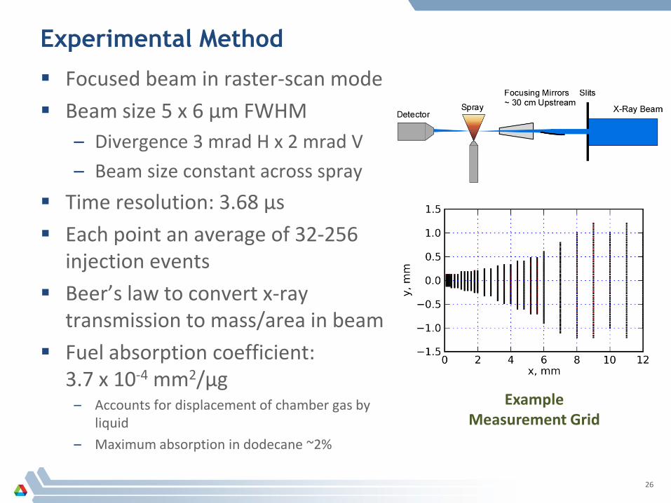
Experimental Method
Focused beam in raster-scan mode Beam size 5 x 6 µm FWHM
– Divergence 3 mrad H x 2 mrad V – Beam size constant across spray
Time resolution: 3.68 µs Each point an average of 32-256
injection events Beer’s law to convert x-ray
transmission to mass/area in beam Fuel absorption coefficient:
3.7 x 10⁻⁴ mm2/µg – Accounts for displacement of chamber gas by
liquid – Maximum absorption in dodecane ~2%
26
Example Measurement Grid

Interpreting X-Ray Phase Contrast Images of Sprays
27
Image courtesy of Philippe Leick, Robert Bosch GmbH
IR Laser Imaging X-Ray Phase Contrast
Images not to scale, different injectors


Vehicle Technologies X-Ray Beamline
Dedicated laboratory at x-ray source – Previous experiments were done in a shared,
general-purpose laboratory – Construction funded by cost-share between BES
and Vehicle Technologies – More time for measurements, collaborations – Explore new capabilities, applications
29
The Advanced Photon Source Argonne National Laboratory
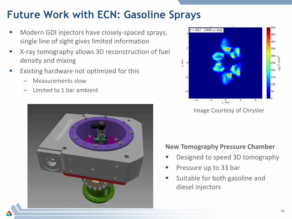
Future Work with ECN: Gasoline Sprays
Modern GDI injectors have closely-spaced sprays, single line of sight gives limited information
X-ray tomography allows 3D reconstruction of fuel density and mixing
Existing hardware not optimized for this – Measurements slow – Limited to 1 bar ambient
30
Image Courtesy of Chrysler
New Tomography Pressure Chamber Designed to speed 3D tomography Pressure up to 33 bar Suitable for both gasoline and
diesel injectors