fuel cell break through - igu · 1 fuel cell break through shinji amaha, kei ogasawara, yasuharu...
TRANSCRIPT

1
Fuel cell break through
Shinji Amaha, Kei Ogasawara, Yasuharu Kawabata, and Hisataka Yakabe, Tokyo Gas Co., Ltd.
Jeongwook Khang, Korea Gas Corporation
1. Introduction
Reducing CO2 emission is a very serious issue for energy companies to be tackled. Although
using renewable energy is the most direct and effective way for this subject, it takes so long time to
come to self-sufficient by renewable energy. Thus during the transition period to the low carbon
society, we must continue using fossil fuels. Using fossil fuels as effectively as possible is another
practical solution to reduce CO2 emission and we must consider how we make efficient use of them.
Fuel cells are expected as one of the effective methods to use fossil fuels because electricity can be
produced successfully through the electrochemical reaction of fossil fuels. While over several
decades, much effort has been paid to the research and development of them, it is not easy to
implement their technology. The past few years, however, at last several fuel cell technologies were
exploited and they are now under popularization. Various types of fuel cells, such as polymer
electrolyte, phosphoric acid, molten carbonate, and solid oxide fuel cells have been developed
intensively and commercialized in Asia, Germany and the United States.
In this report, the current status of fuel cell technologies, especially in Asia is reported.
2. Fuel cells for residential use
In Japan, residential PEFC (Polymer Electrolyte Fuel Cell) systems have been commercialized first
5
① ② ③
Table 1. Comparison of the specification for three different fuel cell systems in Japan.
2
in the world in 2009. Next year
residential SOFC (Solid Oxide Fuel
Cell) systems were also
commercialized. These fuel cell
systems are sold with the standard
brand name “ENEFARM”. ENEFARM
is a micro CHP (Combined Heat and
Power) system and consists of a fuel
cell unit, a hot water tank and a
backup boiler. During a power
generation, by using excess heat at
cell stacks, hot water is produced
simultaneously and stored first in the
hot water tank. Then the stored hot
water is used corresponding to the user’s demand. To avoid the running-out of the hot water,
anytime customers want to use it, the backup boiler supplies hot water and compensate the shortage.
Although ENEFARM is usually operated to follow the user’s electricity demand in each home, the
output power capacity of ENEFARM is lower than the maximum demand. Thus the shortage of the
power is compensated by commercial electricity.
Currently there are three major manufactures for ENEFARM, Panasonic Corporation, Toshiba Fuel
Cell Power Systems Corporation, and Aisin Seiki Co., Ltd. Table 1 shows the specification of
ENEFARM for each company. Panasonic and Toshiba have developed PEFC type systems and Aisin
developed an SOFC system. Although the power generation efficiency of PEFC system is lower than
5
0
2000
4000
6000
8000
10000
12000
0
20000
40000
60000
80000
100000
120000
2009 2010 2011 2012 2013 2014
Su
bsid
ies (
$/u
nit)
Accu
mu
late
d U
nit N
um
be
r
Fiscal Year
Unit Number
Subsidies
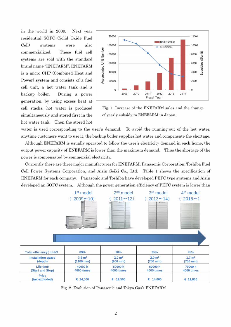
Fig. 1. Increase of the ENEFARM sales and the change
of yearly subsidy to ENEFARM in Japan.
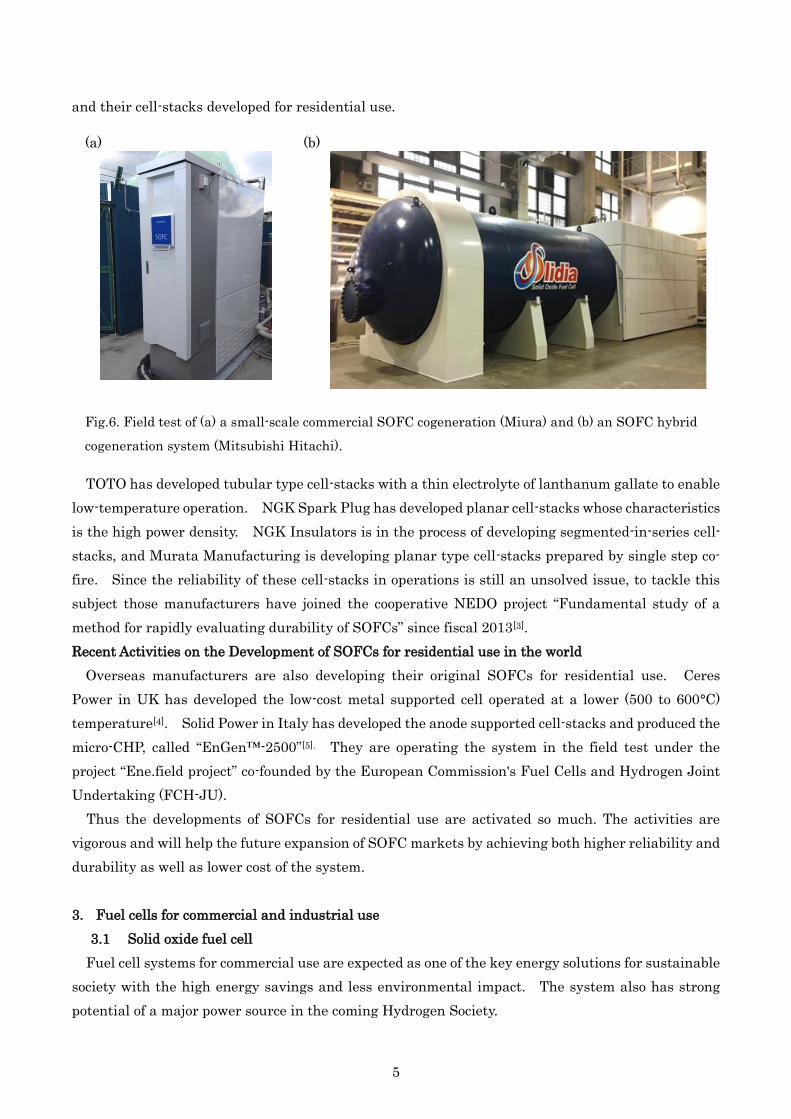
5 Fig. 2. Evolution of Panasonic and Tokyo Gas’s ENEFARM
Total efficiency( LHV) 89% 90% 95% 95%
Installation space
(depth)
3.9 m2
(1100 mm)
2.0 m2
(900 mm)
2.0 m2
(750 mm)
1.7 m2
(750 mm)
Life time
(Start and Stop)
40000 h
4000 times
50000 h
4000 times
60000 h
4000 times
70000 h
4000 times
Price
(tax excluded) € 24,500 € 19,500 € 14,000 € 11,800
1st model
( 2009~10)
2nd model
( 2011~12)
3rd model
( 2013~14)
4th model
( 2015~)
Newest

3
that of SOFC system, the heat recovery efficiency is higher than that of SOFC. Accordingly the
overall efficiency is almost the same for all the FC systems and over 90%.
Figure 1 displays the change of the yearly subsidy by Japanese government to ENEFARM sales
and the increase of the accumulated number of ENEFAEM sold in Japan. Thanks to the subsidies
the ENEFARM sales launched well and the sales number increased gradually. Although the
subsidies decreased with the reduction of the ENEFARM price, the FC business has not been
independent enough yet.
2.1 Polymer electrolyte fuel cell
Tokyo gas and Panasonic have been developing PEFC type ENEFARM. Figure 2 shows the
revolution of Panasonic and Tokyo Gas’s ENEFARM. In 2009 the first ENEFARM system was
commercialized and then, every two years, a new model was released. Along the model change, the
performance of ENEFARM was improved; the efficiency was raised, the size and price was reduced.
The price of the latest model is half the initial model.
With the model change, the sales of ENEFARM increased and this year the accumulated number
of the stock was over 50,000 systems. Tokyo Gas’s near-future target of the ENEFARM stock is
300,000 units in 2020, which is very ambitious number. To popularize ENEFARM more and more,
cost reduction, expansion of the market potential and making ENEFARM more attractive product is
indispensable. For the expansion of the market potential, a new apartment model was developed.
In Tokyo area more than 60% of the new houses are apartment houses, and the adoption of ENEFARM
to apartment houses is very important to spread the market. Thus based on the detached model, an
apartment model which is able to be installed in a small cubicle of apartment buildings was developed
as illustrated in Fig. 3. For smooth installation, the system is separated into three pieces and the
system satisfies the criteria for the apartment installation such as the earthquake resistance and the
wind resistance. Several major developers of apartment buildings have much interest in the high
performance and eco-friendly property of ENEFARM and employed them for their new buildings.
Now many systems of the apartment model have been under installment and around 1,000 units will
Fig. 3. Configuration of an apartment model installed in a cubicle; an FC unit, a Hotwater unit,
and a Backup boiler.
Backup
boiler
Hot
water
unit
Apartment model Detached model
FC
unit
Cubicle

4
be operated in 2015.
2.2 Solid oxide fuel cell
Recent Activities on the Development of SOFC for residential use in Japan
An SOFC is the ultimate power-generating device that is expected to yield the highest efficiency of
power generation among any power generators using fossil fuels. In Japan a demonstrative research
project on SOFCs by New Energy and Industrial Technology Development Organization (NEDO) and
the New Energy Foundation(NEF) of Japan was carried out from 2007 to 2011[1]. In this project, 233
units of SOFC systems were installed in various sites, and a variety of operation data was collected
and evaluated. As a result, it was recognized that residential SOFC system can contribute to saving
the preliminary energy consumptions and CO2 emissions in households.
After the demonstration, JX Nippon Oil & Energy Corporation and Aisin released a residential
SOFC CHP (Combined Heat and Power generation) system in 2011 and in 2012, respectively. Flat
tubular cell-stacks manufactured by Kyocera Corporation were employed in both the unit. Kyocera’s
cell-stack is operated at 700 to 750°C with a high electrical efficiency of 46.5%(LHV) and an overall
energy efficiency of 90%[2]. Stimulated by Kyocera’s success, other ceramic manufactures started to
develop SOFC cell-stacks for residential systems. Since SOFCs can have various geometries and
designs, a number of ceramic manufacturers in Japan make use of their core competence and are
developing their original SOFC technology. Figure 5 shows major SOFC manufacturers in Japan
Fig. 4. Images of apartment buildings that employed ENEFARM.
BRANZ CITY SHINAGAWA-KATSUSHIMACompletion : July 2015 Households :356
THE PREMIER SKY SHINAGAWA-NAKANOBUCompletion : August 2015 Households :100
Fig. 5. Five major SOFC cell stack manufacturers in Japan and their cells.
5
and their cell-stacks developed for residential use.
TOTO has developed tubular type cell-stacks with a thin electrolyte of lanthanum gallate to enable
low-temperature operation. NGK Spark Plug has developed planar cell-stacks whose characteristics
is the high power density. NGK Insulators is in the process of developing segmented-in-series cell-
stacks, and Murata Manufacturing is developing planar type cell-stacks prepared by single step co-
fire. Since the reliability of these cell-stacks in operations is still an unsolved issue, to tackle this
subject those manufacturers have joined the cooperative NEDO project “Fundamental study of a
method for rapidly evaluating durability of SOFCs” since fiscal 2013[3].
Recent Activities on the Development of SOFCs for residential use in the world
Overseas manufacturers are also developing their original SOFCs for residential use. Ceres
Power in UK has developed the low-cost metal supported cell operated at a lower (500 to 600°C)
temperature[4]. Solid Power in Italy has developed the anode supported cell-stacks and produced the
micro-CHP, called “EnGen™-2500”[5]. They are operating the system in the field test under the
project “Ene.field project” co-founded by the European Commission's Fuel Cells and Hydrogen Joint
Undertaking (FCH-JU).
Thus the developments of SOFCs for residential use are activated so much. The activities are
vigorous and will help the future expansion of SOFC markets by achieving both higher reliability and
durability as well as lower cost of the system.
3. Fuel cells for commercial and industrial use
3.1 Solid oxide fuel cell
Fuel cell systems for commercial use are expected as one of the key energy solutions for sustainable
society with the high energy savings and less environmental impact. The system also has strong
potential of a major power source in the coming Hydrogen Society.
5
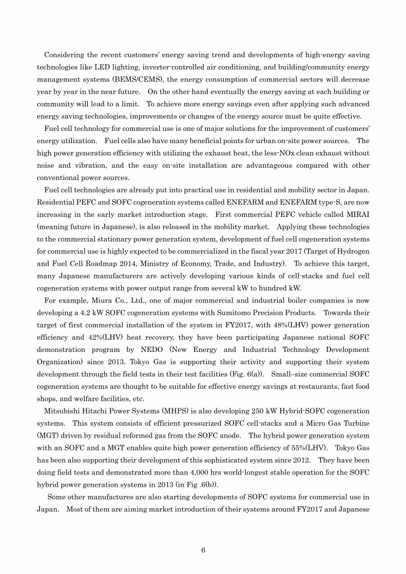
Fig.6. Field test of (a) a small-scale commercial SOFC cogeneration (Miura) and (b) an SOFC hybrid
cogeneration system (Mitsubishi Hitachi).
(a) (b)
6
Considering the recent customers’ energy saving trend and developments of high-energy saving
technologies like LED lighting, inverter-controlled air conditioning, and building/community energy
management systems (BEMS/CEMS), the energy consumption of commercial sectors will decrease
year by year in the near future. On the other hand eventually the energy saving at each building or
community will lead to a limit. To achieve more energy savings even after applying such advanced
energy saving technologies, improvements or changes of the energy source must be quite effective.
Fuel cell technology for commercial use is one of major solutions for the improvement of customers’
energy utilization. Fuel cells also have many beneficial points for urban on-site power sources. The
high power generation efficiency with utilizing the exhaust heat, the less-NOx clean exhaust without
noise and vibration, and the easy on-site installation are advantageous compared with other
conventional power sources.
Fuel cell technologies are already put into practical use in residential and mobility sector in Japan.
Residential PEFC and SOFC cogeneration systems called ENEFARM and ENEFARM type-S, are now
increasing in the early market introduction stage. First commercial PEFC vehicle called MIRAI
(meaning future in Japanese), is also released in the mobility market. Applying these technologies
to the commercial stationary power generation system, development of fuel cell cogeneration systems
for commercial use is highly expected to be commercialized in the fiscal year 2017 (Target of Hydrogen
and Fuel Cell Roadmap 2014, Ministry of Economy, Trade, and Industry). To achieve this target,
many Japanese manufacturers are actively developing various kinds of cell-stacks and fuel cell
cogeneration systems with power output range from several kW to hundred kW.
For example, Miura Co., Ltd., one of major commercial and industrial boiler companies is now
developing a 4.2 kW SOFC cogeneration systems with Sumitomo Precision Products. Towards their
target of first commercial installation of the system in FY2017, with 48%(LHV) power generation
efficiency and 42%(LHV) heat recovery, they have been participating Japanese national SOFC
demonstration program by NEDO (New Energy and Industrial Technology Development
Organization) since 2013. Tokyo Gas is supporting their activity and supporting their system
development through the field tests in their test facilities (Fig. 6(a)). Small–size commercial SOFC
cogeneration systems are thought to be suitable for effective energy savings at restaurants, fast food
shops, and welfare facilities, etc.
Mitsubishi Hitachi Power Systems (MHPS) is also developing 250 kW Hybrid-SOFC cogeneration
systems. This system consists of efficient pressurized SOFC cell-stacks and a Micro Gas Turbine
(MGT) driven by residual reformed gas from the SOFC anode. The hybrid power generation system
with an SOFC and a MGT enables quite high power generation efficiency of 55%(LHV). Tokyo Gas
has been also supporting their development of this sophisticated system since 2012. They have been
doing field tests and demonstrated more than 4,000 hrs world-longest stable operation for the SOFC
hybrid power generation systems in 2013 (in Fig .6(b)).
Some other manufactures are also starting developments of SOFC systems for commercial use in
Japan. Most of them are aiming market introduction of their systems around FY2017 and Japanese
7
major gas companies are promoting and supporting their activities toward future commercialization.
3.2 Molten carbonate fuel cell
MCFC has been commercialized in South Korea by POSCO Energy. The annual production unit
of the company in Pohang is 100 MW and the MCFC products are 100 kW, 300 kW, 2.5 MW and 8×
1.3 MW module plus 10 MW BOP. Fuel cells history in POSCO Energy is like the below table.
The 2.5 MW products consist of two of 1.25
MW module and each module has four stacks.
MCFC Design Basis of 1.2 MW MCFC covers
650°C of operating temperature, 44-49%
electrical efficiency (LHV), 0.55 MW available
heat (to 120°C) and 0.93 MW available heat
(to 50°C).
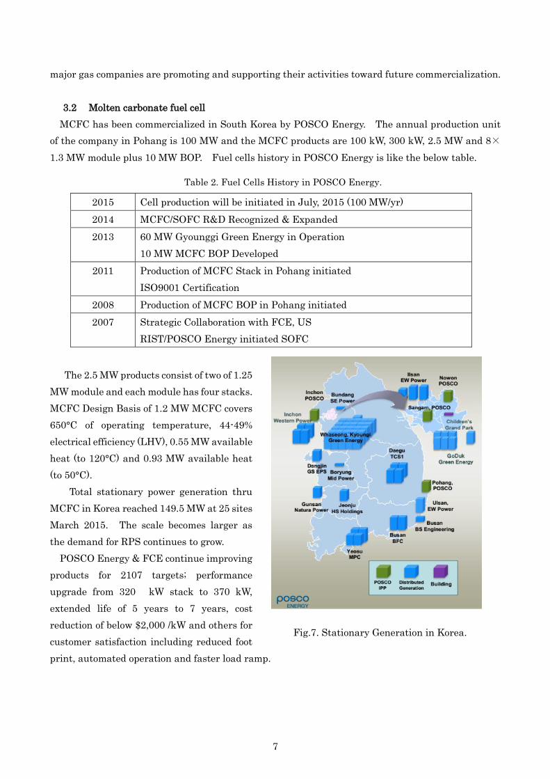
Total stationary power generation thru
MCFC in Korea reached 149.5 MW at 25 sites
March 2015. The scale becomes larger as
the demand for RPS continues to grow.
POSCO Energy & FCE continue improving
products for 2107 targets; performance
upgrade from 320 kW stack to 370 kW,
extended life of 5 years to 7 years, cost
reduction of below $2,000 /kW and others for
customer satisfaction including reduced foot
print, automated operation and faster load ramp.
Table 2. Fuel Cells History in POSCO Energy.
2015 Cell production will be initiated in July, 2015 (100 MW/yr)
2014 MCFC/SOFC R&D Recognized & Expanded
2013 60 MW Gyounggi Green Energy in Operation
10 MW MCFC BOP Developed
2011 Production of MCFC Stack in Pohang initiated
ISO9001 Certification
2008 Production of MCFC BOP in Pohang initiated
2007 Strategic Collaboration with FCE, US
RIST/POSCO Energy initiated SOFC
Fig.7. Stationary Generation in Korea.

8
Additional value proposition via technology convergence has been actively explored. Platform
products aim higher fuel utilization and secondary generation of which electrical efficiency is higher
than 60% and diversified (H2-rich) fuel & multi-purpose products. In Cascade Modules, un-reacted
fuel in the first module is further utilized in the second module resulting in increase of total fuel
utilization and electrical efficiency. Diverse configurations with more than 2 modules are possible,
however operational and control logic becomes complicate.
Process engineering has been advanced for the variety of hydrogen-rich fuel and other feedstock.
Due to the RPS and building regulations, fuel cell market for stationary generation in Korea is
steadily growing. To accommodate growing market as well as to prepare for the future non-RPS
market, the MCFC maker put an effort to develop high-efficiency hybrid products, while keep
improving current MCFC products for lower cost and longer life. Recently, large size market for IGCC
and SNG plats and/or H2-rich fuel from chemical plats emerges fast, and engineering process for fuel
Fig. 8. Classical Module and Cascade Module.
Fig. 8. ?????????????????????????????
Fig. 9. Applications for Diversified Fuel.
Note: SNG: Synthetic Natural Gas, IGFC: Integrated Gasifier Fuel Cell, ADG: Anaerobic
Digest Gas, BOG: Boil-Off Gas

9
treatment are also being actively developed.
4. New technology related fuel cell
4.1 Trigeneration using SOFC
An SOFC is a very excellent distributed power generator and expected to be applied to industrial
and business use. However an issue in the adoption is how to use the excess heat because usually
heat demand is very small in such as office buildings. One of possible solutions for this problem is a
trigeneration (or co-production) concept [6-7]. The idea of the SOFC trigeneration system is that it
can produce hydrogen in addition to electricity and heat.
The configuration of an SOFC trigeneration system is shown in Fig.7. The principle of the
trigeneration is as follows. Using the excess heat of an SOFC, through steam reforming reaction,
fuel is reformed to hydrogen rich gas at an additional reformer. Then the reformate gas is refined
by a purifier, a CO shift converter and a PSA (Pressure Swing Adsorption). Instead of using the
excess heat to produce steam or hot water, it is used to produce hydrogen. The trigeneration system
can control the ratio of hydrogen production to steam or hot water freely and thus when the heat
demand is small hydrogen is generated and stored (there are several ways to store hydrogen).
Several years ago, Tokyo Gas proposed this idea and proved that it is possible to produce hydrogen
effectively by using excess heat of an SOFC system. The actual demonstration was carried out using
a 10 kW SOFC system at Tokyo Institute of Technology, and in more advanced, a PEFC system was
combined the SOFC trigeneration system. The picture of the SOFC and PEFC hybrid system is
displayed in Fig. 8. Through the demonstration it was proved that around 10% of electricity can be
additionally produced to the SOFC output by the hydrogen production. Now Tokyo Gas and
Mitsubishi Hitachi are planning to apply this system to a hydrogen refueling station and demonstrate
its validity in Tokyo Olympic.
4.2 Ultra highly efficient SOFC
Fig.7. Configuration of as SOFC and PEFC
hybrid system.
SOFC
Reformer
Natural Gas
SOFC system
Shift Convertor
Compressor
PSA H2 storage tank
Exhaust
Cooling
H2 Refiner
Pure H2
PEFC system
Reformate
Pure H2
Power
Pre-reformer
Reformate
Heat
Power
Off-gas
SOFC
PEFC
,SOFC (4.5kW×2)
Radiator
Combustor
H2 cylinder
PSA
Controller
Hotwater tankPEFC (0.8 kW)
Fig.8. Outline of the demonstrated SOFC and
PEFC hybrid system.

10
In usual SOFCs have the highest power efficiency among fuel cells. However enhancing the
efficiency of small scale SOFC systems higher than up-to-date large scale combined cycle thermal
power plants can make them more competitive and is beneficial to develop and expand gas business
markets. For example, major business and industrial customers in Japan have more power demands
than thermal ones, and have potential to achieve greater environmental and economical benefits by
using power generator with higher efficiency.
One effective way to increase power generating efficiency of SOFC systems is, for example,
combining an SOFC with a turbine in large-scale systems. However the operation of the combined
system is complicated and difficult, and moreover this system cannot be adopted to smaller one.
Tokyo Gas is making a different approach to increase the efficiency of SOFC systems. The main
principle is refining the fuel exhaust gas from the cell part and reusing the refreshed gas as a fuel
again. To realize this concept multiple cell-stacks configuration is employed. The point is that, by
removing carbon dioxide (CO2) and water in the exhaust fuel from the first SOFC stack, the unreacted
fuel can be concentrated so as to be reused effectively as a fuel for the second stack (see Fig. 9).
Thereby the fuel utilization for the overall system is improved greatly, which in turn improves power
generating efficiency. This method is applicable in principle not only to large scale but also to
medium and small scale systems.
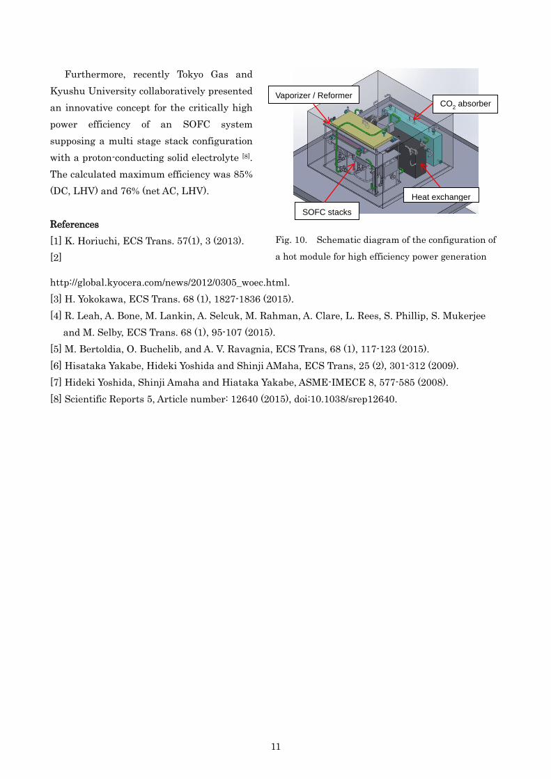
The R&D activities of Tokyo Gas include manufacturing a hot module for proving the concept. As
schematically shown in Fig. 10, three SOFC stacks were incorporated in the hot module together with
fuel refining equipment filled with CO2 absorbing agent, and also a water condensation unit at outer
vicinal of the module. Since this unit is too small to be thermally sustainable, the insufficiency of
the heat is assisted by an external heater. Although the thermal dissipation was compensated by
the heater, this demonstration unit showed very excellent performance. The maximum fuel
utilization reached 92.0% attaining power efficiency of 77.8% (DC, LHV) at the rated output power of
1.4 kW. More efforts will be made in order to eventually demonstrate high-efficiency power
generation by actual systems.
Fig. 9. Schematic diagram of an SOFC concept with high fuel utilization
Hot exhaust gas
Off air
SOFC
Off air
Fuel reproduction technology
Anode
Cathode
SOFC
Anode
Cathode
SOFC2
Anode
Cathode
SOFC
Anode
Cathode
SOFC1
Combustor
Heat exchanger
Exhaust gas
Vaporizer
Steamreformer
Water
Methane
Air
Blower
Mixer
11
Furthermore, recently Tokyo Gas and
Kyushu University collaboratively presented
an innovative concept for the critically high
power efficiency of an SOFC system
supposing a multi stage stack configuration
with a proton-conducting solid electrolyte [8].
The calculated maximum efficiency was 85%
(DC, LHV) and 76% (net AC, LHV).
References
[1] K. Horiuchi, ECS Trans. 57(1), 3 (2013).
[2]
http://global.kyocera.com/news/2012/0305_woec.html.
[3] H. Yokokawa, ECS Trans. 68 (1), 1827-1836 (2015).
[4] R. Leah, A. Bone, M. Lankin, A. Selcuk, M. Rahman, A. Clare, L. Rees, S. Phillip, S. Mukerjee
and M. Selby, ECS Trans. 68 (1), 95-107 (2015).
[5] M. Bertoldia, O. Buchelib, and A. V. Ravagnia, ECS Trans, 68 (1), 117-123 (2015).
[6] Hisataka Yakabe, Hideki Yoshida and Shinji AMaha, ECS Trans, 25 (2), 301-312 (2009).
[7] Hideki Yoshida, Shinji Amaha and Hiataka Yakabe, ASME-IMECE 8, 577-585 (2008).
[8] Scientific Reports 5, Article number: 12640 (2015), doi:10.1038/srep12640.
Fig. 10. Schematic diagram of the configuration of
a hot module for high efficiency power generation
test.
Heat exchanger
CO2 absorber
SOFC stacks
Vaporizer / Reformer