friends of upminster windmill - webydofiles7.webydo.com/91/9158794/uploadedfiles/91a... · friends...
TRANSCRIPT
1
50pWhere sold
Friends of Upminster WindmillRegistered Charity Number 1097976
www.upminsterwindmill.co.ukTel: 0300 030 1803

2
Friends of Upminster WindmillChairman
Dennis Coombs, 1 Highview Gardens, Upminster RM14 2YU01708 221298
SecretaryPaul Sainsbury
TreasurerJean Webb, 2 Fairkytes Avenue, Hornchurch. RM11 1XS
01708 [email protected]
Vice-ChairmanMartin Withers, 40 Chelmer Road, Upminster. RM14 1QT
01708 [email protected]
Membership SecretaryIan Ross, 33 Grosvenor Gardens, Upminster. RM14 1DL
01708 [email protected]
EditorMartin Withers, 40 Chelmer Road, Upminster. RM14 1QT
01708 [email protected]
Upminster Windmill Preservation TrustChairman
Dennis Coombs, 1 Highview Gardens, Upminster RM14 2YU01708 221298

3
From the Chairman
Following the success of our application to Heritage Lottery Fund,work is proceeding to bring the restoration plans to fruition. Anarchitect has been appointed to manage the construction work.Planning consent had already been obtained for the new Educa-tion and Training Centre. The architect will now finalise those plansand assist with the appointment of a building contractor. Thebuilding work will probably start in the summer and be completedearly in 2016. A millwrighting consultant will be appointed in theSpring to ensure we are ready to appoint one or more millwrightsfor the restoration work, which we hope to start as soon as the newbuilding is available.
In the meantime, the archaeology of the site has continued. Wehave been quite staggered to discover such extensive remains ofthe former steam mill. Cliff’s article in this Newsletter providesmore details. We will be exploring ways of preserving this site, ifpossible as an open space to ensure public enjoyment.
Our partnership with the National Mills Archive is also bearing fruit.Their web-based photographic archive is expected to be launchedin the Spring, enabling ready access to thousands of mill relateditems. The partnership links our two websites. We have lodged100 images, including recently restored photographs and some ofour spectacular computer graphical images produced by Cliff andJonathan Green. If all goes to plan, our next Newsletter will providea link to this material. DC.
Quiz Night
The windmills annual quiz night will be held on Sat 21st Feb,starting at 7.30pm, in the Main Hall, St Laurence Church - price £6per person, bring you own food and drink. All profits go towardsthe upkeep of our mill. This is a popular event, and tables aregoing fast, so please book early to avoid disappointment.

4
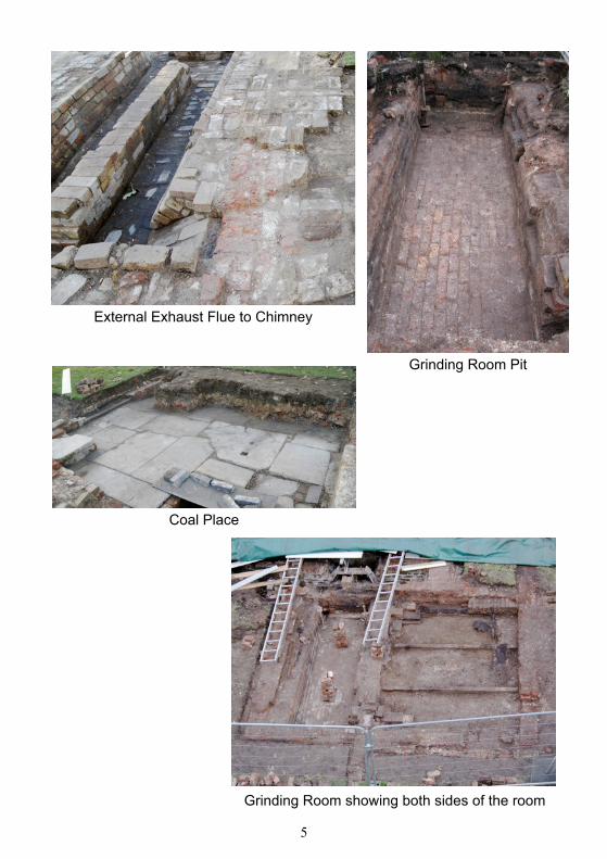
Archaeology at the Windmill.A Happy New Year from the Archaeology TeamThe Archaeology continues throughout the winter, except for atwo week break over the festive season. Our attention is mainlyconcentrated on the Steam Mill. To date we have uncovered theboiler room showing brickset flues and chimney base, with anexternal flue running from the brickset to the chimney. Thebrickset used refractory bricks especially imported for itsconstruction. Three quarters of the Coal Place (we had to haltthe excavations there as we would not have been able to pegdown the tarpaulin) has been excavated, including the areawhere the face of the boiler sat, and the run off pipe, which wasstill in situ. We also established that the eastern end of the northgable wall of the coal place, was thicker than the rest. We thinkthis was to strengthen the North West corner of the boiler housegable wall, where the boiler face protruded.We have also uncovered the area where the steam engine waslocated, finding the anchor bolts for the engine mounting, andvarious mouldings and marks on the engine plinth with which wecan now place the engine accurately in its original location. We
Brickset under fluesEngine plinth, and crankshaft pits
5
External Exhaust Flue to Chimney
Grinding Room Pit
Coal Place
Grinding Room showing both sides of the room
6
have also established the crankshaft pits and the iron bearingframe for the flywheel bearing. It was also discovered that theflywheel was part recessed in the western wall of engine house.This was to allow alignment of the gearing mechanism in thegrinding room.We have uncovered the grinding room, this building was in twoparts. Part one (the Western side) consisted of a brick built pitwhich housed the machinery to turn the two sets of mill stones.This pit revealed several recesses along its length on both sides,which allowed for the correct alignment of the machinery tooperate in the confined space. Part two (the Eastern side) wasa timber floored area used to access the stones and hoppers.Some of the wooden floor was still in situ although burnt. Therewas an air vent built in to the dividing wall at ground levelbetween the grinding room pit and the wooden floored area. Wealso established that the steam mill butted up to the meal house,which is more evidence that the meal house was built at thesame time as the Windmill.The archaeology team have now been able to accuratelymeasure all the features excavated, and plot heights as well aspositions of the various features, so that they can be faithfullybe reproduced on maps and reconstructions. We are nowcontinuing to clean up these areas and looking for the pig courts,so that we can tie these buildings together and establish the lineof the road from the windmill round to the stables. We still havethe Granary, Coal Office, Original Stables, Cart Shed and theremainder of the Meal Room to excavate, which we hope tohave completed by the spring.Paul Sainsbury & the Archaeology Team.

7
Steam MillTwo and a half years ago a project was started to assess the steam mill that once worked in tandem with the windmill, and attempt to make a computer reconstruction. Despite the scant number of documents and photographs available, a look-alike was produced as a 3D model, which many of you will now have seen. A large amount of supposition and calculated guesswork were used in making that first model, but now that a full archaeological investigation of the site has reached an advanced stage, a re-assessment and re-modelling has been possible to a much higher order of accuracy than previously.
Footings as revealed by the archaeology.C Chimney; BBS Boiler brick setting; CH Coal House; ER Engine Room;GR Grinding Room; MH Meal House; EP Engine plinth; FP Flywheel pit;
GS Gear sump
Last season’s work on the steam mill also brought an unexpectedoutcome. Right from commencement of the dig it became evidentthe remains were more extensive than first thought, and inappraising these it proved fortuitous that the ISSES (International

8
Static Steam Engine Society – the gurus on industrial steam plantsand their history) were consulted for advice. They immediatelydeclared that what we have at Upminster is of National importance,in that remains of a Bell Crank engine site, especially one withsupporting post 1900’s photographs, is extremely rare.
The following is a brief summary of the steam mill and site, takinginto account the knowledge gained recently.
Boiler. The original boiler type is not known, but most probabilitywas of a Wagon Top design. Such boilers had a cross sectionalshape that was rectangular in the lower half and semi-circular atthe top. Their fire was underneath and had flues to redirect theexhaust gasses around the sides for additional heating. In 1911this was replaced with a Cornish style boiler from the Colchesterfirm of Davey Paxman, and the ISSES have traced John ArkellAbraham’s order for this in the Paxman archive. It was 14ft longand 4ft in diameter, and would have cost around £80 (£7400 todayadjusting for the value of the £ over the period, but not takingaccount of the relative market value at each date).
The new boiler shell shortly after delivery to the mill in July 1911.This old photograph has been colour tinted to make the boiler distinguishablefrom its surroundings. Behind the boiler is the Abrahams’ horse and cart for
coal deliveries.

9
Unlike a Wagon top boiler, the Cornish boiler had a fire tubepassing through its centre, so the old brick setting in which theoriginal boiler was mounted had to be rebuilt, providing a chamberat the exhaust end of the fire tube to direct the hot gasses into asystem of two under flues; the entire assembly then being enclosedin a brick box.
Left: Outer brick enclosure.Right: The face of the boiler protruded into the Coal House for stoking. Two
iron trapdoors provided access to the under flues for cleaning.
Left: The boiler shell sat above flues built into the floor.Right: The fire tube and sides of the shell were enclosed to direct hot
exhaust gasses into the under flues to give added heating.
10
Engine. This was an extensively modified Boulton and Watt(B&W), Bell Crank engine, the alterations effectively convertingit into a tank mounted table engine, with grasshopper beam todrive its pumps. It had a piston of approximately 16ins dia. witha stroke of 2ft, and was designed to run at 40 rpm, producing6 brake horsepower. The flywheel was 10ft dia. and would haveweighed in at just over 1 ton.
B&W kept records of every engine they built, with details of thedate, purchaser, and site where it was to be installed. The ISSEShave carried out extensive searches in the B&W archive and otherreferences, but have not yet found the origin of the Upminsterengine. This implies that the engine was bought second or thirdhand as a private transaction, not through B&W, although someof the components needed for the modification would have comefrom the B&W works. In addition many of the details of the enginemounting and drive train were in keeping with B&W practice,indicating that an experienced engineer was in charge of theinstallation; if not employed by B&W, trained by them.
Every B&W engine was slightly different, but many had featuresin common. The archaeology has revealed a number of importantdetails associated with the engine’s mounting: marks left in theconcrete and brickwork; size and height of the engine plinth;anchor bolts, and an iron flywheel bearing stand. By comparingthese to drawings supplied by the Science Museum and the B&Warchive of similar engines, it has been possible to gauge the exactsize of the engine’s cistern, and determine the alignment of thecrankshaft. Establishing the exact centre line of the crankshafthas been vital, as that dictated the layout and dimensions withinthe grinding room, and in turn how the various mechanisms wereassembled.
In general the engine was set far closer to the side wall of the millthan first expected, with the flywheel running partly in a slot formedin the mill’s west wall. This westward placement meant that all theequipment in the grinding room, including the stones, had to belined up in a narrow zone down one side of the room.

11
Such an engine would have cost £450 new in 1811, which convertsto £33,900 at the present value of the £, but like the boiler, thisdoes not take account of relative market values.
Grinding Room. The arrangement of crown wheels, stone nuts,and sack hoist was known previously from an old photograph, butthe archaeology has shown their exact positions, and clarifieddetails of the gear sump housing the drive system. The numberof governors and steelyards used for the tentering gear to controlthe stones were, however, uncertain, as the photo did not havesufficient clarity, but with the aid of accurate site dimensions and3D drawing, the problem has now been solved. There was onegovernor, three steelyards, and two counter weights, which exactlymatch the fragmentary details shown in the photo.
The stone floor and bin floor remain largely as previously modelled,
The engine set on a raised plinth of brick and concrete with the crankshaftpassing under the cold water cistern.

12
In the image above, the south gable wall, and the internal dividingwall between the engine and grinding rooms have been omitted.
Auxiliary drive shaft. A drive shaft to transfer power from thesteam engine into the windmill to assist in runningmachines like the bolter and sack hoist, was a fact recordedmore than sixty years ago, but the records do not say how itwas coupled to the engine. The current archaeology hasprovided the essential evidence to show how this was done: aclearance slot in the side of the grinding room gear sump at itssouthern end, to accommodate a large gearwheel fitted to theend of the primary drive shaft, being the clue.
In the archive there is a photograph taken in the late 50’s, afterthe steam mill interior had been dismantled, that shows two cast
simply with some adjusts to take account of the building’sdimensions found by the archaeology. The one exception hasbeen the jockey wheel to operate the sack hoist: new dimensionsand a reappraisal of the photograph has shown this was not onthe bin floor, but suspended like a pendulum under the stone floornear to the governor. After correcting this error in the model, it nowmatches vague shapes shown in the old photo.

13
iron plain gears leaning against a wall, each about 4ft dia. Wherethey were used, if at all, was not known. With the discovery by thearchaeologists of the clearance slot, their purpose has becomeobvious, especially as one has a square hole in its hub thatmatches the primary drive shaft. By drawing the gears to scale andsuperimposing them on the 3D model, a working arrangement caneasily be constructed for transferring the drive to a shaft runningalone the top of the wall in the meal house, and into the windmill.A third small gear was required to reverse the direction of rotation,and it is possible that such a gear is the one that has survived andis currently stored in the windmill.
Three gear combination. The smaller top gear is connected to the auxiliaryshaft passing through the south gable wall and down the length of the Meal
House, and into the windmill. The mechanism can be disengaged by means ofa lever that slides the small gear out of mesh.

14
At the end of the auxiliary shaft where it terminated in the base ofthe windmill, was a novel freewheel device. This was described in1948 by an engineer, Waring Sholl, who stated that if both windand steam power were running together, ‘a competition mightarise as to who would be first’. The windmill’s mechanisms werefragile compare to those of the steam mill, so if the windmill ranfaster than the engine, its mechanism could be damaged by tryingto drive the steam mill.
The freewheel device comprised a wooden belt pulley, and aratchet and pawl. The ratchet was driven by the auxiliary shaft, andthe pawl was attached to the wooden pulley. When the engine ranfaster than the windmill, the pawl remained engaged and turnedthe pulley, but when the windmill was the faster of the two, thepawl disengaged, allowing the pulley to spin freely on its axle andrun ahead.
3D model. The model of the steam mill will continue to be updatedas the archaeology and research provide more information. Anew animation is also being prepared. Please contact me if youwould like a full copy of the Sketchup [email protected] Cliff Featherston

15
Flint Knapping Lecture
On the 22nd November 2014 a flint knapping lecture anddemonstration was held at the Old Chapel in St Mary’s LaneUpminster. This was a joint venture between The Friends of theOld Chapel and the Upminster Windmill Archaeology Group. Thelecture was given by a post graduate from Southampton Universitycalled James Dilley. James gave a couple of excellent talks on flintknapping whilst demonstrating the art and skill of flint knapping,and producing a couple of flint axes. James covered flint toolusage and knapping skills through the various periods in time fromthe Palaeolithic through Mesolithic to the Neolithic period. Jamesalso had a range of flint and antler tools and weapons on display,with some items for sale. The session ended with a wonderfulbuffet lunch. The turnout was good with around 36 peopleattending, who all enjoyed the demonstration and the lunch. Moreinformation about James Dilley’s work and skills can be found onhis website www.ancientcraft.co.uk Thanks go to Gemma and theFriends of the Old Chapel for their hospitality and help in arrangingthis event. Paul Sainsbury

16
Our NewsletterBack numbers of the Newsletter are available on the Mill Website.This Newsletter is available electronically, saving printing andpostage costs. If you would like to receive the Newsletterelectronically, please let Ian Ross know by emailing him [email protected] next Newsletter will be published in April. Contributions arewelcome and should be sent to the Editor by early April..
Open Days 2015Please note these will be the final open days of the Mill until therefurbishment is completed.
April 4, 5 & 18,19May 2, 3 & 9, 10 & 30June 6, 7 & 20, 21July 4, 5 & 18, 19Aug 1, 2 & 15, 16Sept 5, 6 & 19, 20
Special Events - Mill open from 12 noonJune 7 Craft FairJune 21 Art Exhibition in Old Chapel. We are planning to
show restored photographs, computer graphics etc of the Mill. More details in April Newsletter
July 5 Classic Cars Display