frequency synthesizer sps-20 - spectran.orgspectran.org/pdf/sps20_datasheet.pdf · 7 sps-20...
TRANSCRIPT

Frequency synthesizer
SPS-20
2015

3
Application
SPS-20 is designed for using as a reference generator and a highly stable
heterodyne in the wide frequency range 9 kHz…20 GHz for testing various elec-
tronic devices and systems during their research, development, operation and
maintenance.
SPS-20 provides the specified harmonic signal of wide frequency range with
output power control and different types of modulation.
Specification
– Dimensions: 178x85x25 mm
– Weight: 0,6 kg
Dimension drawing of SPS-20
− Operating frequency range, …………...…………..……9 kHz…20 GHz
− Frequency resolution, Hz……………………...…….………………0,001 − Frequency stability …………………………………………………1×10
-6
− Output power range, dBm*:
160 MHz < f < 20 GHz……...………..…………………………… -10…+10
− Output power resolution, dB …………………………….………….…0,5
− Output power accuracy , dB ……………………..……...…………… 0,8
− Phase adjustment range, deg …………..……………….....….……….360
− Phase adjustment resolution, deg ………………………………...…..0,03
− Harmonics, dBc*:

4
160 < f < 1000 MHz…………………………..………………...………< -40
1 < f < 20 GHz……………………………………….………..….……..< -50
− Spurious (non-harmonic) components, dBc ……………….……… < -60
− Spurious (non-harmonic) components (offset >1 kHz ), dBc:
160 < f < 2500 MHz……………………………..…………..……….... < -88
2,5 < f < 5 GHz…………………………………………….…..……..…< -82
5 < f < 10 GHz ……………………………………………..…………...< -76
10 < f < 20 GHz …………………………………………..….................< -70
− Frequency switch time (since download via the external interfaces), us
.................................................................................................................. 5
− Output VSWR ………………………………………………..……..... <2
Pulse modulation mode
− Pulse on-time ………………………………………….……....100ns…1s
– Pulse rise, ns ……………………………………………………….... <20
− Pulse period ……………………………………………..…....200ns…2s
– Isolation, dB………………………………………………………..…>70
− RF connector type ………………………….…………….. 2,92/1,27 mm
− Power consumption, W………………………………………….…….30
* Parameters for frequencies from 9 kHz to 160 MHz are not specified.
Reference input
− Signal frequency at the reference input «10 MHz» (CMOS), MHz
…………………………………………………………………………10
− Phase noise at offset 10 kHz, dBc/Hz ………………………….....-140
Phase noise
F, MHz Phase noise, dBc/Hz
100 Hz 1 kHz 10 kHz 100 kHz 1 MHz 10 MHz
200 -100 -131 -143 -144 -143 -149
500 -93 -123 -135 -135 -134 -142
1000 -86 -116 -128 -129 -128 -138
4000 -73 -104 -117 -117 -117 -129
8000 -69 -99 -112 -111 -111 -127
10000 -67 -97 -110 -110 -110 -124
12000 -64 -96 -107 -108 -107 -116
14000 -61 -94 -107 -107 -106 -117
16000 -61 -93 -105 -106 -104 -118
18000 -62 -92 -104 -105 -104 -118
20000 -60 -91 -103 -103 -102 -119
21000 -58 -91 -103 -103 -104 -121

5
Typical output power level
Typical phase noise at 20 GHz

6
Typical phase noise at 200 MHz
Typical harmonics

7
SPS-20 structure
Frequency synthesizer SPS-20 is constructed on base of indirect synthesis
system with direct digital synthesis elements. SPS-20 consists of functional
blocks:
− reference oscillator with direct digital synthesis system, providing step
adjustment of the master oscillator frequency 10…20 GHz;
− control unit based on FPGA and a microprocessor;
− division and filtering unit, for a generation of frequency 9 kHz…10
GHz, lowering of level harmonic and subharmonic spectrum compo-
nents and control of output power level.
SPS-20 structure
Direct digital synthe-
sis system
Reference Oscillator
1 GHz
Master oscillator
10-20 GHz
Dividing and filtering
frequency module
«10 MHz Input»
Output «SHF»
Control Module
«LAN»
«USB»
8
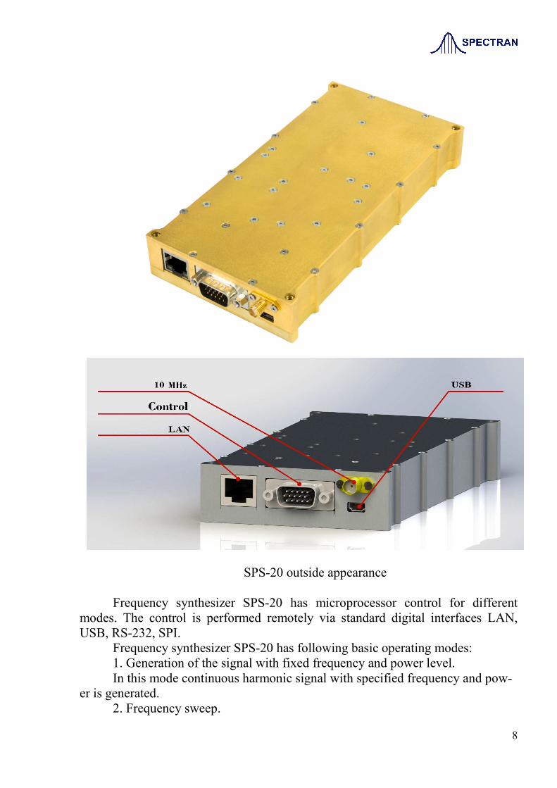
SPS-20 outside appearance
Frequency synthesizer SPS-20 has microprocessor control for different
modes. The control is performed remotely via standard digital interfaces LAN,
USB, RS-232, SPI.
Frequency synthesizer SPS-20 has following basic operating modes:
1. Generation of the signal with fixed frequency and power level.
In this mode continuous harmonic signal with specified frequency and pow-
er is generated.
2. Frequency sweep.

9
In this mode frequency sweep is performed with specified step and switch
time from the start to stop frequency point.
3. Power sweep.
In this mode power sweep is performed with specified step and switch time
from the start to stop power level point.
SPS-20 control connector pinouts # Pin Type Parameter Notes
1 POWER +10 V 2,5А
2 POWER +10 V
3 POWER +27 V 100 mA
4 POWER -7 V 50 mA
5 GND COMMON
6
7 RS232_RX output
8 RS232_TX input
9 GND COMMON
10 SPI SCLK input
11 SPI SDIO input/output
12 SPI CS input
13 GND COMMON
14 Input 1 Synchronizing input input TTL 3.3 V
15 Output 1 Synchronizing output output TTL 3.3 V
Operating SPS-20
NOTE! Good grounding and sufficient external fan cooling are needed
for frequency synthesizer SPS-20!
Setting modes of operating for the frequency synthesizer SPS-20 is per-
formed via digital interfaces using SCPI commands.
SCPI determines standard for the commands and queries syntax for test and
measurement equipment. SCPI command or query is a text ASCII string, sent into
the test and measurement equipment via physical interface (LAN, USB, RS-232).
Valid length of the string is limited to 255 characters.
In general, command (query) of SCPI standard is a series of keywords, di-
vided by colons. After the keywords space-divided parameters follow. Example of
SCPI command:
POWer[:AMPLitude] MAXimum|MINimum
Here POWer and AMPLitude – are keywords, MAXimum and MINimum
– parameters.
SCPI queries are used for reading data and control measurement equipment
parameters and differ from SCPI commands by the presence of ‘?’ symbol at the
end of the string. Response to the query is a text ASCII string with requested val-
ue.

10
Another special symbols, using for marking SCPI command and queries are
shown into the table below.
Symbol Description Example
| Vertical line between the
keywords indicates that alter-
native options can be used.
Result will depend on selected
value.
REFerence[:SOURce] INTernal
|External
Parameters INTernal and EXTernal –
are alternative options, any of the op-
tions can be used.
[ ] Squared brackets indicate that
keywords or parameters can
be missed when writing a
command. These implied pa-
rameters will be considered,
even if they are excluded.
FREQuency[:CW] MAXimum
|MINimum
Keyword CW can be missed.
< > Angle brackets indicate that
the word shouldn’t be used lit-
erally. This word should be
replaced by parameter value.
PULM:INTernal:PERiod <val>
<unit>
In this command <val> and <unit>
should be replaced by real values for the
period of internal pulse modulation and
units for period time
PULM:INTernal:PERiod 250 ms
{ } Figure brackets indicate that
the parameter should be used
in command one time only,
few times, or not be used at
all. If you using several pa-
rameters in one command,
they must be comma separat-
ed.
LIST:POWer[:AMPLitude] <val>
<unit>{,<val> <unit>}
Оne power value in the list
LIST:POWer 5 dBm
Several values of power level in list
LIST:POWer 1 dBm, 2 dBm, 3 dBm
When writing SCPI commands and queries keywords and parameters also
can be shortened to parts, marked with capital letters. Moreover, this SCPI com-
mands and queries are non-casesensitive. So these following commands are equal:
TRIG:SOUR IMM
TRIGger:SOURce IMMediate
Trigger:Source Immediate
trig:sour imm
11
Syntax of the units of measurement, transmitted as parameters in SCPI
commands:
- units of time:
ns – nanoseconds
us – microseconds
ms – milliseconds
s – seconds
- units of frequency:
Hz – hertz
kHz – kilohertz
MHz – megahertz
GHz – gigahertz
- units of power level:
dBm – decibel referred to 1 milliwatt
- units of phase:
deg – degrees
rad – radians
SCPI commands and queries are divided on the two types: common for all
kinds of test and measurement equipment and specialized for specific instrument.
Common SCPI commands and queries begin with an asterisk with following
keyword:
*IDN?
This is query of identification information of the instrument. Identification
information has the following form:
<company_name>, <instrument_model>, <model_number>, <firm-
ware_revirsion >
*RST
This command resets most parameters of the instrument to the factory val-
ues. Description of every SCPI command in this documentation contains factory
value affected by the command.
*SAV
This command saves current instrument state in specific area of the nonvola-
tile memory. After the power-on of the device this state is restored.

12
*TRG
This command starts process of frequency or power sweep, if external inter-
face is chosen as trigger source. For more information about synchro signal
sources, go to the TRIGger:SOURce command description.
Specific SCPI command and queries:
ABORt
This command aborts frequency or power sweep of frequency synthesizer. If
the parameter of INITiate:CONTinuous command set to ON, sweep immediate-
ly starts from start point.
INITiate:CONTinuous ON|OFF
INITiate:CONTinuous?
This command sets repeating or single type of frequency or power sweep.
Performing of the command does not affect current sweep process.
ON Continuous mode of sweep, after the finishing of current sweep cycle
new one starts from the beginning automatically.
OFF Single mode of sweep, after the finishing of current sweep cycle for
new one synchro signal is needed according to the source chosen by TRIG-ger:SOURce command.
Default value of parameter– OFF.
INITiate
This command allows frequency or power sweep.
[LIST:]TRIGger:SOURce BUS|IMMediate|EXTernal
[LIST:]TRIGger:SOURce?
This command sets source for synchro signal to start frequency or power
sweep.
BUS Start of sweep by SCPI command *TRG via external interfaces.
IMMediate Immediate start of sweep.
EXTernal Start of sweep by external trigger.
Default parameter value– BUS.
LIST:TYPE STEP|LIST
LIST:TYPE?
This command sets type of frequency and power sweep.
STEP Intermediate frequency or power level points are spaced at
equal intervals from each other.
LIST Intermediate frequency or power level points have arbitrary
values.
Default parameter value – STEP.

13
LIST:MODE AUTO|MANual
LIST:MODE?
This command sets automatic or manual (using LIST:MANual command)
mode for access to intermediate points of sweep range.
AUTO Auto sweep from start to stop point.
MANual Switch to the intermediate points of sweep range manually us-
ing LIST:MANual command.
Default parameter value– AUTO.
LIST:MANual <val>|UP|DOWN
This command performs switch to arbitrary intermediate point of sweep
range that set by the parameter <val>. Parameter value should be less than number
of sweep points, set by command SWEep:POINts (sweep mode STEP) or
numbers of frequency values or power level values in the list (sweep mode LIST).
UP Switch to the next intermediate point of sweep range.
DOWN Switch to the previous intermediate point of sweep range.
To execute this command it is necessary to set parameter specified by
LIST:MODE command in MANual.
Example:
LIST:MAN 5
This command performs switch to fifth intermediate point of sweep range.
LIST:POWer[:AMPLitude] <val> <unit>{,<val> <unit>}
This command determines a list of power level values for sweep. For power
level sweep in accordance with list of values, it is necessary that parameter defined
by the command LIST:TYPE specifies the type of sweep as LIST.
Example:
LIST:POW 0.1 DBM,0.2 DBM,0.1 DBM,0.3 DBM,0.1 DBM,-0.1 DBM
This command sets power level sweep of six values.
Maximum number of power level values in list– 100.
LIST:FREQuency <val> <unit>{,<val> <unit>}
This command determines a list of frequency values for sweep. For fre-
quency sweep in accordance with list of values, it is necessary that parameter de-
fined by command LIST:TYPE specifies the type of sweep as LIST.
Example:
LIST:FREQ 10 GHZ,12 GHZ,14 GHZ,16 GHZ
This command sets frequency sweep of four values.
Maximim number of frequency values in list – 100.
SWEep:POINts <val>
SWEep:POINts?

14
This command sets number of points for frequency or power level sweep.
Parameter matters only in case you chose sweep mode STEP by command
LIST:TYPE.
Example:
SWEEP:POINTS 2001
Command sets number of sweep points 2001.
The range of valid values 2…65535.
Default value – 2.
SWEep:TIME <val> <unit>
SWEep:TIME?
This command sets sweep time. If this command is executed while the sig-
nal generator is in auto sweep time mode, the manual sweep time mode is activated
and the new sweep time value is applied. The sweep time cannot be set to a value
less than the automatic sweep time mode provides.
The sweep time is the duration of the sweep from the start point to the stop
point. It does not include the retrace time that occurs between sweep repetitions.
Range of the valid values 5 us … 99 s.
Default parameter value – 200 ms.
Response for a query is a string with sweep time value in microseconds.
SWEep:TIME:AUTO ON|OFF
SWEep:TIME:AUTO?
This command sets the sweep time mode.
ON This choice enables the signal generator to automatically calculate and
set the fastest possible sweep time.
OFF This choice allows to select the sweep time manually. The sweep time
cannot be set to a value faster than the automatic mode provides. To set the sweep
time refer to :SWEep:TIME command.
Default parameter value – OFF.
FREQuency:MODE FIXed|CW|LIST
FREQuency:MODE?
This command sets the frequency mode of the synthesizer.
FIXed/CW These options are synonymous. Any currently running frequen-
cy sweep is turned off, and the current CW frequency settings are used to control
the output frequency.
LIST This choice selects the frequency sweep mode. Type of sweep is
defined by LIST:TYPE command.
Default parameter value – CW.
FREQuency [:CW] <val> <unit>|MAXimum|MINimum|UP|DOWN
FREQuency [:CW]?

15
This command sets output frequency.
UP Increases the current frequency by the value set with the FRE-Quency[:CW]:STEP.
DOWN Decreases the current frequency by the value set with the
FREQuency[:CW]:STEP.
Example:
FREQ:CW 20 GHZ
This command sets output frequency of synthesizer 20 GHz.
Values MAXimum, MINimum and also output frequency default value
are determined by specification of frequency synthesizer.
Response on the query is a string with frequency value in Hz.
FREQuency[:CW]:STEP <val> <unit>
FREQuency[:CW]:STEP?
This command sets the incremental step value for the frequency.
Example:
FREQ:STEP .5 GHZ
This command sets step of the frequency in manual mode 500 MHz.
Default parameter value – 100 MHz
Response on the query is a string with frequency step value in Hz.
FREQuency:STARt <val> <unit>|MAXimum|MINimum
FREQuency:STARt?
This command sets the frequency start point for a sweep.
Example:
FREQ:START 520 MHZ
This command sets start value for frequency sweep 520 MHz.
Values MAXimum, MINimum, and default start value are defined by spec-
ification of frequency synthesizer.
Response on the query is a string with start frequency value in Hz.
FREQuency:STOP <val> <unit>|MAXimum|MINimum
FREQuency:STOP?
This command sets the frequency stop point for a step sweep.
Example:
FREQ:STOP 10 GHZ
This command set stop value for frequency sweep 10 GHz.
Values MAXimum, MINimum, and default stop value are defined by spec-
ification of frequency synthesizer.
Response on the query is a string with stop frequency value in Hz.
POWer:MODE FIXed|LIST
POWer:MODE?

16
FIXed Any currently running power level sweep is turned off, and the
current fixed power level settings are used to control the output power.
LIST This choice selects the power level sweep mode. Type of sweep
is defined by LIST:TYPE command.
Default parameter value – FIXed.
POWer[:AMPLitude] <val> <unit>|MAXimum|MINimum|UP|DOWN
POWer[:AMPLitude]?
This command sets output power level.
UP Increases output power level by the value set with command
POWer[:AMPLitude]:STEP.
DOWN Decreases output power level by the value set with command
POWer[:AMPLitude]:STEP.
Example:
POW .5 DBM
This command sets power level on level 0,5 dBm.
Values of MAXimum, MINimum, and default power level are defined by
frequency synthesizer specification.
Response on the query is a text string with power level value in decibels re-
ferred to 1milliwatt.
POWer[:AMPLitude]:STEP <val> <unit>
POWer[:AMPLitude]:STEP?
This command sets the incremental step value for the power level in manual
mode.
Example:
POW:STEP 0.5 DBM
This command sets power level step 0,5 dBm in manual mode.
Default parameter value – 0,1 dBm.
Response on the query is a text string with power level step value in decibels
referred to 1 milliwatt.
POWer:STARt <val> <unit>|MAXimum|MINimum
POWer:STARt?
This command sets start point for power level sweep.
Example:
POW:START -20 DBM
This command sets start value of power level -20 dBm.
Values of MAXimum, MINimum, and default start value of power level
are defined by frequency synthesizer specification.
Response on the query is a text string with start power level value in deci-
bels referred to 1 milliwatt.

17
POWer:STOP <val> <unit>|MAXimum|MINimum
POWer:STOP?
This command sets stop point for power level sweep.
Example:
POW:STOP 10 DBM
This command sets stop value of power level 10 dBm.
Values of MAXimum, MINimum, and default stop value of power level
are defined by frequency synthesizer specification.
Response on the query is a text string with stop power level value in decibels
referred to 1 milliwatt.
PHASe[:ADJust] <val> <unit>|MAXimum|MINimum|UP|DOWN
PHASe[:ADJust]?
This command adjusts the phase of the output signal.
UP This command adjusts phase of the output signal by 1 degree
up.
DOWN This command adjusts phase of the output signal by 1 degree
down.
Example:
PHAS:ADJ 5 DEG
This command adjusts the phase shift of the output signal to 5 degrees up.
Values of MAXimum, MINimum are defined by frequency synthesizer
specification.
Response on the query is a text string with phase value in degrees.
REFerence[:SOURce] INTernal|EXTernal
REFerence[:SOURce]?
This command sets as a source of reference signal for synthesizer either in-
ternal high stable quartz oscillator or external signal with 10 MHz frequency.
INTernal High quartz oscillator is selected as a source of reference signal.
EXTernal a source of reference signal chosen External signal with 10
MHz frequency is selected as a source of reference signal.
Default value of parameter – INTernal.
AM:SOURce INTernal|EXTernal
AM:SOURce?
This command selects amplitude modulation and sets source of the modulat-
ing signal.
INTernal Internal source of modulating signal.
EXTernal External signal is selected as modulating signal.
Default parameter value – INTernal.
AM:INTernal:FREQuency <val> <unit>

18
AM:INTernal:FREQuency?
This command sets a frequency of modulating signal for amplitude modula-
tion with internal source of modulating signal.
Example:
AM:INT:FREQ 5 kHz
This command sets frequency of modulating signal for amplitude modula-
tion with internal source 5 kHz.
The range of valid values 1 Hz … 100 kHz.
Default parameter value – 20 kHz.
Response on the query is a text string with frequency of modulating signal
for amplitude modulation with internal source of modulating signal in Hz.
AM:INTernal:FUNCtion:SHAPe SINE|TRIangle|SQUare|RAMP
AM:INTernal:FUNCtion:SHAPe?
This command sets waveform shape of modulating signal for amplitude
modulation with internal source of modulating signal.
Example:
AM:INT:FUNC:SHAP SINE
This command sets sine shape of modulating signal for amplitude modula-
tion.
SINE Sine modulating waveform shape.
TRIangle Triangle modulating waveform shape.
SQUare Square modulating waveform shape.
RAMP Sawtooth modulating waveform shape.
Default parameter value – SINE.
AM:DEPTt <val>
AM:DEPTh?
This command sets depth of amplitude modulation in percents.
Example:
AM:DEPT 30.5
This command set the depth of amplitude modulation 30,5%.
Range of valid values 0 … 100%.
Default parameter value – 100%.
Response on query is a text string with value of depth of amplitude modula-
tion in percents.
PULM:SOURce INTernal|EXTernal
PULM:SOURce?
This command selects pulse modulation and sets source of modulating sig-
nal.
INTernal Internal source of modulating signal.
EXTernal External signal is selected as modulating signal.

19
Default parameter value – INTernal.
PULM[:INTernal]:PERiod <val> <unit>
PULM[:INTernal]:PERiod?
This command sets period of pulses for pulse modulation with internal
source of modulating signal. Value should be more or equal to pulse on-time value,
defined by command PULM[:INTernal]:PWIDth.
Example:
PULM:INT:PER .5 s
This command sets period of pulse for pulse modulation with internal source
500 ms.
Range of valid values 200 ns … 2 s.
Default parameter value – 250 ms.
Response on query is a text string with value pulses period for pulse modu-
lation with internal source of modulating signal in nanoseconds.
PULM[:INTernal]:PWIDth <val> <unit>
PULM[:INTernal]:PWIDth?
This command sets on-time of pulses for pulse modulation with internal
source of modulating signal. Value should be less or equal to value of pulse period,
defined by command PULM[:INTernal]:PERiod.
Example:
PULM:INT:PWID 100 MS
This command sets pulses on-time for pulse modulation with internal source
100 ms.
Range of valid values 100 ns … 2 s.
Default parameter value – 100 ns.
Response on query is a text string with value of pulses on-time for pulse
modulation with internal source of modulating signal in nanoseconds.
FM:SOURce INTernal|EXTernal
FM:SOURce?
This command selects frequency modulation and sets source of the modulat-
ing signal.
INTernal Internal source of modulating signal.
EXTernal External signal is selected as modulating signal.
Default parameter value – INTernal.
FM:INTernal:RATE <val> <unit>
FM:INTernal:RATE?
This command sets a modulation rate for frequency modulation with internal
source of modulating signal.
Example:

20
FM:INT:RATE 5 kHz
This command sets modulation rate for frequency modulation with internal
source 5 kHz.
The range of valid values 1 Hz … 100 kHz.
Default parameter value – 20 kHz.
Response on the query is a text string with modulation rate for frequency
modulation with internal source of modulating signal in Hz.
FM:INTernal:FUNCtion:SHAPe SINE|TRIangle|SQUare|RAMP
FM:INTernal:FUNCtion:SHAPe?
This command sets waveform shape of modulating signal for frequency
modulation with internal source of modulating signal.
Example:
FM:INT:FUNC:SHAP SINE
This command sets sine shape of modulating signal for frequency modula-
tion.
SINE Sine modulating waveform shape.
TRIangle Triangle modulating waveform shape.
SQUare Square modulating waveform shape.
RAMP Sawtooth modulating waveform shape.
Default parameter value – SINE.
FM:DEViation <val> <unit>
FM:DEViation?
This command sets frequency deviation for frequency modulation.
Example:
FM:DEV 1 MHz
This command set the frequency deviation for frequency modulation 1 MHz.
The range of valid values 1 Hz … 128 MHz.
Default parameter value – 1 MHz.
Response on query is a text string with value of frequency deviation for fre-
quency modulation in Hz.
OUTPut ON|OFF
OUTPut?
This command turns on/off output power of frequency synthesizer.
ON Output signal on.
OFF Output signal off.
Default parameter value – OFF.
Response on query is a text string with current state of a synthesizer output.
OUTPut:MODulation ON|OFF
OUTPut:MODulation?

21
This command turns on/off modulation of output signal for frequency syn-
thesizer.
ON Enable modulation of output signal.
OFF Disable modulation of output signal.
Default parameter value – OFF.
Response on query is a text string with current state of a synthesizer output.
SYSTem:COMMunication:LAN:IP <ipstring>
SYSTem:COMMunication:LAN:IP?
This command sets the frequency synthesizer’s local area network (LAN)
internet protocol (IP) address for IP network connection. The <ipstring> variable is
the frequency synthesizer’s IP address, formatted as xxx.xxx.xxx.xxx. The setting
enabled by this command is not affected by the frequency synthesizer power-on or
*RST command. Restart of the frequency synthesizer is needed to apply new IP-
address.
Example:
SYST:COMM:LAN:IP 192.168.2.127
The preceding example sets the frequency synthesizer’s LAN IP address
192.168.2.127.
Response on query is a text string with current IP address of a synthesizer.
SYSTem:COMMunication:LAN:PORT <val>
SYSTem:COMMunication:LAN:PORT?
This command sets the frequency synthesizer’s local area network (LAN)
internet protocol (IP) port defined by <val> value. The setting enabled by this
command is not affected by the frequency synthesizer power-on or *RST com-
mand. Restart of the frequency synthesizer is needed to apply new port value.
Example:
SYST:COMM:LAN:PORT 5023
The preceding example sets the frequency synthesizer’s LAN port 5023.
Response on query is a text string with current port of a synthesizer.
SYSTem:COMMunication:SERial:BAUD <val>
SYSTem:COMMunication:SERial:BAUD?
This command sets the baud rate for the RS–232 interface. The setting ena-
bled by this command is not affected by a frequency synthesizer power-on or
*RST command. Restart of the frequency synthesizer is needed to apply new baud
rate.
The variable <val> is an integer value corresponding to baud rates: 14400,
19200, 38400, 56000, 57600, 115200, 128000 or 256000.
Example:
SYST:COMM:SER:BAUD 19200

22
The preceding example sets the baud rate for serial communication to
19200.
Response on query is a text string with current baud rate of a synthesizer.
Programming of frequency synthesizer SPS-20 via SPI-interface
Command codes for control of synthesizer via SPI are shown in the table below
Address, MSB
Data, MSB
Parameter Value
Length Value
Length
0x01 8 bits F_out,Bits[47:0] 48 bits Output frequency
(mHz)
0x02 8 bits P_out[15:0] 16 bits Output power
(dBm*0,1)
0x04 8 bits Output ON 0 Output power on
0x05 8 bits Output OFF 0 Output power off
0x13 8 bits Mod[7:0] 8 bits
Enable (0х01)/
Disable (0х00) am-
plitude modulation
(АМ)
Enable (0х02)/
Disable (0х00) pulse
modulation (PAM)
0x21 8 bits Freq_mod[23:0] 24 bits Modulating frequen-
cy for АМ (Hz)
0x22 8 bits Lev_ mod [7:0] 8 bits Modulation depth
for АМ (%)
0x11 8 bits Time_mod [31:0] 32 bits Pulse period for
PAM (ns)
0x12 8 bits Time_imp[31:0] 32 bits Pulse on-time for
PAM (ns)
0x03 8 bits Phase[15:0] 16 bits
Phase adjustment
∆=∆
1422
phaseФ π
Frequency sweep mode
0x08 8 bits Freq_start[47:0] 48 bits Start frequency
0x09 8 bits Freq_stop[47:0] 48 bits Stop frequency
0x20 8 bits Step_time[23:0] 24 bits Switch time to the
next point

23
Address, MSB
Data, MSB
Parameter Value
Length Value
Length
0x16 8 bits Trigger_source[7:0] 8 bits
=0 by step time
=1 by external trig-
ger
0x0F 8 bits Start_sweep 0 Frequency sweep on
0x10 8 bits Stop_sweep 0 Frequency sweep off
0x0D 8 bits Freq_step[47:0] 48 bits Frequency sweep
step
0x0C 8 bits Sweep_point[15:0] 16 bits Number of sweep
points
0x14 8 bits Type_sweep[7:0] 8 bits Frequency sweep
(0х01)
Power sweep mode
0x0A 8 bits Pow_start[15:0] 16 bits Start power
0x0B 8 bits Pow_stop[15:0] 16 bits Stop power
0x20 8 bits Step_time[23:0] 24 bits Switch time to the
next point
0x16 8 bits Trigger_source[7:0] 8 bits
=0 by step time
=1 by external trig-
ger
0x0F 8 bits Start_sweep 0 Power sweep on
0x10 8 bits Stop_sweep 0 Power sweep off
0x0E 8 bits Pow_step[15:0] 16 bits Power sweep step
0x0C 8 bits Sweep_point[15:0] 16 bits Number of sweep
points
0x14 8 bits Type_sweep[7:0] 8 bits Power sweep (0х02)
Amplitude modulation
0х21 8 bits am_freq 24 bits AM frequency
0х22 8 bits am_depth 8 bits AM depth
Pulse amplitude modulation
0х11 8 bits pam_period 32 bits PAM period
0х12 8 bits pam_ontime 32 bits PAM on-time
frequency modulation
0х24 8 bits fm_rate 24 bits FM rate
0х25 8 bits fm_dev 32 bits FM deviation

24
Data transmission via serial peripheral interface (SPI)