for model mmu-516l-enaz.simpleapp2.net/sites/default/files/documents/manuals/mmu516l.pdfnaztec...
TRANSCRIPT
Naztec Operations Manual
For
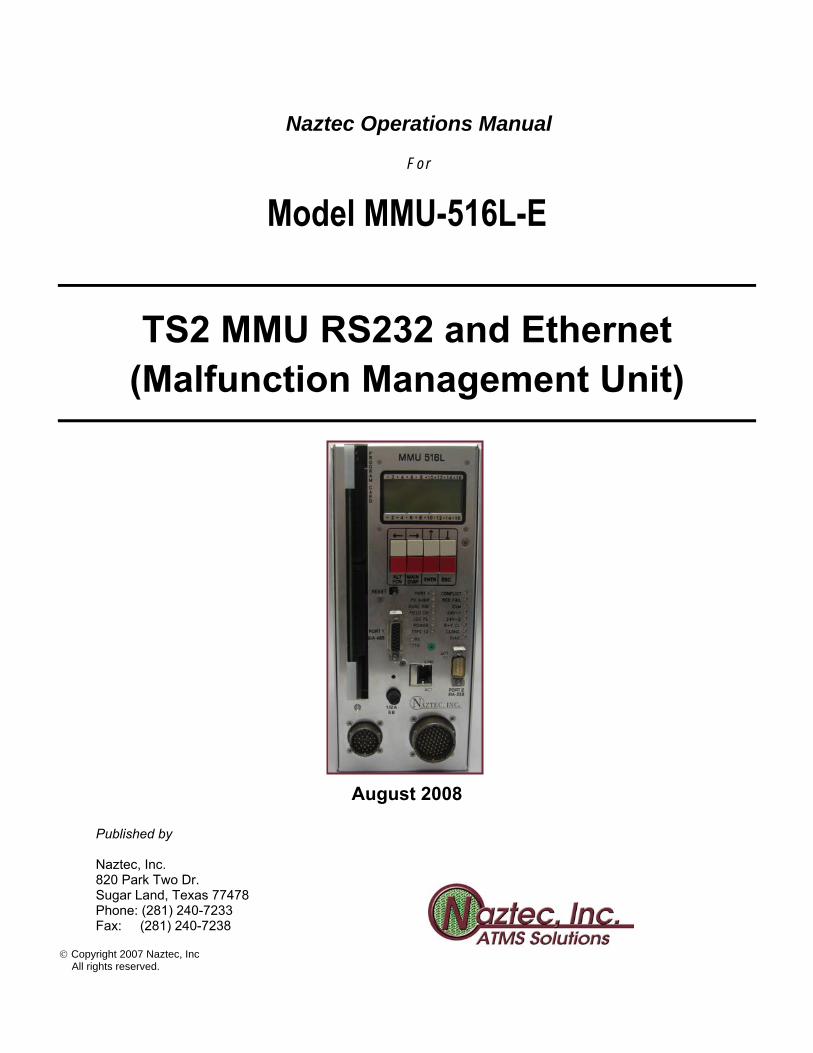
Model MMU-516L-E
TS2 MMU RS232 and Ethernet (Malfunction Management Unit)
August 2008
Published by Naztec, Inc. 820 Park Two Dr. Sugar Land, Texas 77478 Phone: (281) 240-7233 Fax: (281) 240-7238
Copyright 2007 Naztec, Inc All rights reserved.

Naztec Terms Of Use Agreement USE OF THIS NAZTEC, INC. MANUAL IS SUBJECT TO THESE TERMS OF USE.
Agreement Please read this User Agreement carefully before using the information provided in this Manual. This Agreement explains the terms and conditions governing the use of this Manual ("Terms of Use"), and it is your responsibility to read and understand them. By using the Manual you expressly agree to be bound by these Terms of Use and to follow them as well as all applicable laws and regulations governing the Manual. If you do not agree to be bound by these Terms of Use, you may not access or use this Manual. Naztec, Inc. reserves the right to change these Terms of Use at any time, effective immediately upon posting the Manual from our company website. By continuing to use the Manual after we post any such change, you accept the revised Terms of Use. If you violate these Terms of Use, Naztec, Inc. may terminate your use of the Manual, bar you from future use of the Manual, and take appropriate legal action against you.
Permitted Use You agree that you are only authorized to read, view and retain a copy of pages of this Manual for your own personal use, and that you will not duplicate, download, publish, modify or otherwise distribute the material on this Manual for any purpose other than to review product information for personal use or the use of a government or non-profit organization.
No Commercial Use Users may not use this Manual for any commercial purposes such as to sell merchandise or services of any kind. You must obtain our prior written consent to make commercial offers of any kind, whether by advertisements, solicitations, links, or by any other form of communication. Naztec, Inc. will investigate and take appropriate legal action against anyone who violates this provision.
Copyright All content included on this Manual, including text, graphics, logos, icons, images, and software is the property of Naztec, Inc. or its content suppliers and is protected by United States and international copyright laws. This compilation (that is, the collection, arrangement and assembly) of all content on this Manual is the exclusive property of Naztec, Inc. and is protected by U.S. and international copyright laws. Naztec, Inc. reserves the right to revise the pages of the Manual or withdraw access to them at any time.
Trademarks The Naztec logo and trademarks that appear throughout the Manual belong to Naztec, Inc., its affiliates or third party trademark owners, and are protected by U.S. and international trademark laws. Without Naztec Inc express prior written permission, you may not display or use in any manner, the Naztec logos or trademarks. Nothing in this Manual shall be construed as granting any license or other right to the intellectual property or other proprietary rights of Naztec, Inc., its affiliates or any third party, whether by estoppels, implication or otherwise. All contents of the Manual are: © Copyright 2000 Naztec, Inc. or its licensors. All Rights Reserved.
Disclaimer of Warranty YOU UNDERSTAND AND EXPRESSLY AGREE THAT YOUR USE OF THE MANUAL AND THE INFORMATION FOUND THERE IS ENTIRELY AT YOUR RISK. NAZTEC, INC. AND ITS AFFILIATES AND LICENSORS MAKE NO WARRANTIES OR ANY REPRESENTATIONS OF ANY KIND, EITHER EXPRESS OR IMPLIED, INCLUDING BUT NOT LIMITED TO WARRANTIES OF TITLE OR NON-INFRINGEMENT OR IMPLIED WARRANTIES OF MERCHANTABILITY, FITNESS FOR A PARTICULAR PURPOSE, NON-INFRINGEMENT OR OTHER VIOLATION OF RIGHTS IN RELATION TO THE AVAILABILITY, ACCURACY, VALIDITY, COMPLETENESS, RELIABILITY OR CONTENT OF THESE PAGES AND/OR THE MANUAL. NAZTEC, INC. SHALL NOT BE LIABLE FOR ANY DIRECT, INDIRECT, INCIDENTAL, SPECIAL OR CONSEQUENTIAL DAMAGES, LOST PROFITS OR FOR BUSINESS INTERRUPTION ARISING OUT OF THE USE OF OR INABILITY TO USE THIS MANUAL, EVEN IF NAZTEC, INC. HAS BEEN ADVISED OF THE POSSIBILITY OF SUCH DAMAGES. TO THE MAXIMUM EXTENT PERMITTED BY LAW, YOU HEREBY RELEASE AND FOREVER WAIVE ANY AND ALL CLAIMS YOU MAY HAVE AGAINST NAZTEC, INC., ITS AFFILIATES AND LICENSORS FROM LOSSES OR DAMAGES YOU SUSTAIN IN CONNECTION WITH YOUR USE OF THE MANUAL.
SOME JURISDICTIONS DO NOT ALLOW EXCLUSION OF CERTAIN WARRANTIES OR LIMITATIONS OF LIABILITY, SO THE ABOVE LIMITATIONS OR EXCLUSIONS MAY NOT APPLY TO YOU. THE LIABILITY OF NAZTEC, INC. WOULD IN SUCH CASE BE LIMITED TO THE GREATEST EXTENT PERMITTED BY LAW.
Applicable Law These Terms of Use and all legal issues related to the Manual shall be governed by the laws of the State of Texas, without regard to conflict of laws principles. You agree that any dispute involving these terms of use or this Manual will be heard in a court with jurisdiction in Fort Bend County, Texas. You further agree that the prevailing party in any legal action will be entitled to recover its reasonable attorneys fees incurred in connection with that action. If for any reason a court of competent jurisdiction finds any provision of these Terms of Use to be unenforceable, the remaining terms will continue in full force and effect.
Entire Agreement These Terms of Use are the final and entire agreement between you and Naztec, Inc. with respect to this subject and replace any and prior or contemporaneous understandings or agreements, written or oral, regarding the subject matter. Any waiver of any provision of these Terms of Use shall be effective only if in writing and signed by an authorized representative of Naztec, Inc.
Naztec Series 500 Malfunction Monitors Model MMU-516 L Page 3
TABLE OF CONTENTS
1.0 OVERVIEW............................................................................................................................................................6
1.1 TS1 and TS2 Modes of Operation....................................................................................................................................... 6
1.2 Monitoring ............................................................................................................................................................................ 6
1.3 Relay Outputs ....................................................................................................................................................................... 7
1.4 Front Panel............................................................................................................................................................................ 7
1.5 Other Features...................................................................................................................................................................... 8
1.6 Data Logging......................................................................................................................................................................... 8
2. MONITORING........................................................................................................................................................9
2.1 Standard Monitoring ........................................................................................................................................................... 9 2.1.1 Channel Inputs................................................................................................................................................................ 9 2.1.2 Conflict........................................................................................................................................................................... 9 2.1.3 Red Failure and Red Enable Input.................................................................................................................................. 9 2.1.4 Skip Yellow Failure...................................................................................................................................................... 10 2.1.5 Minimum Yellow Failure ............................................................................................................................................. 10 2.1.6 Minimum Yellow Change Plus Red Clearance Failure................................................................................................ 10 2.1.7 +24 Volt DC I & II Inputs ............................................................................................................................................ 11 2.1.8 Controller Voltage Monitor Input ................................................................................................................................ 11 2.1.9 Port 1 Disable Input...................................................................................................................................................... 12 2.1.10 Local Flash Input.......................................................................................................................................................... 12 2.1.11 AC Line Voltage .......................................................................................................................................................... 12 2.1.12 Power-up Sequencing................................................................................................................................................... 12
2.2 Diagnostic Monitoring ....................................................................................................................................................... 13 2.2.1 Programming Card Monitoring .................................................................................................................................... 13 2.2.2 RAM Test ..................................................................................................................................................................... 13 2.2.3 FLASH Monitoring ...................................................................................................................................................... 13 2.2.4 EEPROM Monitoring................................................................................................................................................... 13 2.2.5 Microprocessor Monitoring.......................................................................................................................................... 13
2.3 Enhanced Monitoring ........................................................................................................................................................ 14 2.3.1 Indication Failure ......................................................................................................................................................... 14 2.3.2 Field Check Failure ...................................................................................................................................................... 14
2.4 Enhanced Connectivity ...................................................................................................................................................... 15 2.4.1 Flashing Yellow Arrow................................................................................................................................................ 15 2.4.2 FYA Monitoring........................................................................................................................................................... 16 2.4.3 Yellow Mapped Walk .................................................................................................................................................. 17
3. STATUS INDICATORS .......................................................................................................................................18
3.1 Monitor Status .................................................................................................................................................................... 18
3.2 Channel Status.................................................................................................................................................................... 20
Naztec Series 500 Malfunction Monitors Model MMU-516 L Page 4
4. PROGRAMMING CARD .....................................................................................................................................21
4.1 Setup .................................................................................................................................................................................... 21
4.2 Permissive Channel Jumpers ............................................................................................................................................ 21
4.3 Minimum Flash Time Jumpers......................................................................................................................................... 22
4.4 Minimum Yellow Change Channel Disable Jumpers ....................................................................................................... 22
4.5 Latch +24 Volt Fault Jumper............................................................................................................................................ 22
4.6 Latch CVM Fault Jumper.................................................................................................................................................. 22
5. RESET PUSHBUTTON .......................................................................................................................................23
6. LCD AND KEYPAD.............................................................................................................................................24
7. OPERATION........................................................................................................................................................26
7.1 Default Status Screens ....................................................................................................................................................... 26
7.2 Menus and Screens............................................................................................................................................................. 27 7.2.1 Status Menu.................................................................................................................................................................. 27 7.2.2 History Menu................................................................................................................................................................ 28
8. REMOTE/LOCAL ACCESS WITH DATA PORT 2.............................................................................................41
8.1 Data Port 2 Interface.......................................................................................................................................................... 41
8.2 Remote Access .................................................................................................................................................................... 41
8.3 Help Menu........................................................................................................................................................................... 42
8.4 Reports ................................................................................................................................................................................ 42 8.4.1 Programming Report .................................................................................................................................................... 42 8.4.2 Power Log Report ........................................................................................................................................................ 45 8.4.3 Fault Log Report .......................................................................................................................................................... 47 8.4.4 Trace Log Report.......................................................................................................................................................... 50
8.5 Miscellaneous Reports & Commands............................................................................................................................... 51 8.5.1 Present Fault Report ..................................................................................................................................................... 51 8.5.2 AC Line Voltmeter Function........................................................................................................................................ 51 8.5.3 Clear Power Log Function ........................................................................................................................................... 51 8.5.4 Clear Fault Log Function ............................................................................................................................................. 51
Naztec Series 500 Malfunction Monitors Model MMU-516 L Page 5
9. APPENDIX A - CONNECTOR PINOUTS ...........................................................................................................52
9.1 Type 16 Connector A ......................................................................................................................................................... 52
9.2 Type 16 Connector B.......................................................................................................................................................... 53
9.3 Type 12 Connector A ......................................................................................................................................................... 54
9.4 Type 12 Connector B.......................................................................................................................................................... 55
9.5 Port 1 Connector ................................................................................................................................................................ 56
9.6 Port 2 Connector ................................................................................................................................................................ 56
9.7 Programming Card Connector P1.................................................................................................................................... 57
9.8 Programming Card Connector P2.................................................................................................................................... 58
10. APPENDIX B - SPECIFICATIONS......................................................................................................................59
10.1 ELECTRICAL ................................................................................................................................................................... 59 10.1.1 POWER........................................................................................................................................................................ 59 10.1.2 AC INPUTS ................................................................................................................................................................. 59 10.1.3 DC INPUTS ................................................................................................................................................................. 59 10.1.4 RELAY OUTPUTS...................................................................................................................................................... 60 10.1.5 COMMUNICATION PORT 1 ..................................................................................................................................... 60 10.1.6 REMOTE ASYNCHRONOUS PORT 2...................................................................................................................... 60
10.2 TIMING FUNCTIONS...................................................................................................................................................... 61
10.3 CONNECTORS.................................................................................................................................................................. 62
10.4 SIZE..................................................................................................................................................................................... 62
10.5 ENVIRONMENTAL ......................................................................................................................................................... 62
11. APPENDIX C – FLASHING YELLOW ARROW EXAMPLES............................................................................63
11.1 Channels 9-12 Pedestrian Movement Assignment Example ......................................................................................... 64
11.2 Channels 13-16 Pedestrian Movements Assignment Example....................................................................................... 65
Naztec Series 500 Malfunction Monitors Model MMU-516 L Page 6
1.0 OVERVIEW The Naztec MMU-516L Malfunction Management Unit monitors the traffic signal indications for conflicting signal indications, improper sequencing of signals, incorrect timing and improper signal voltage levels. The MMU-516L Malfunction Management Unit complies with the National Electrical Manufacturers Association (NEMA) Standard TS2-1998, Section 4, for 16 Channel Malfunction Management Units. The MMU-516L is also compatible with TS1 cabinets, and emulates 12 Channel Conflict Monitor Units (CMU) conforming to the NEMA Standard TS1-1989. 1.1 TS1 and TS2 Modes of Operation
The MMU-516L Type 16 mode monitors three 115 Volt AC input circuits (Green/Walk, Yellow, and Red/Don’t Walk) for up to 16 load switch “Channels”. The MMU-516L Type 12 mode monitors four 115 Volt AC input circuits (Green, Yellow, Red and Walk) for up to 12 load switch “Channels”. These two operating modes of the MMU (Type 16 and Type 12) are selected using the external Type Select input to the monitor. The Type 16 mode is selected when less than 8 VDC (connection to cabinet Logic Ground) is applied to the Type Select input (logic state True). The Type 12 mode is selected when at least 16 VDC (no connection to pin) is present at the Type Select input (logic state False). The current mode is indicated by the TYPE 12 LED (illuminated if the Type 12 mode is selected). 1.2 Monitoring
The MMU-516L provides the following monitoring functions to insure that the terminal facility is operating properly:
1. Active channels are monitored for conflicting indications as defined by the Programming Card permissive channel jumpers. 2. Each channel is monitored for “red failure” when all channel outputs are “dark” for more than 0.7 seconds. 3. Yellow intervals are monitored to guarantee at least 2.7 sec. of yellow clearance. The time interval from the termination of green until the start of green on the next conflicting channel is also checked to insure that yellow plus red clearance is at least 2.7 sec. 4. The Red Enable input and AC Line input are constantly monitored as required by the NEMA TS2 specification. 5. The +24 Volt I input and +24 Volt II input are monitored to insure that cabinet and/or controller power supplies are operating at the proper voltage. 6. Checks to insure that no more than one indication is present on a single channel 7. Green + Yellow indication monitoring (if enabled) 8. Check for Programming Card not inserted properly 9. Channel inputs agree with SDLC controller data (Type 16 TS2 mode)

Naztec Series 500 Malfunction Monitors Model MMU-516 L Page 7
In addition, the following inputs are constantly monitored to insure proper operation of the terminal facility:
Voltage Monitor input Type Select input +24 Volt Monitor Inhibit input Port 1 Disable input Local Flash input Reset input (same as Reset Switch)
The MMU-516L also monitors the internal hardware within the unit to insure that the unit is operating properly. The MMU performs a check sum on non-volatile (data) and program memory at power up and performs periodic RAM diagnostics to insure proper operation of the unit. A watchdog timer circuit monitors the microprocessor and will override the MMU and set the Output Relay to the “fault” state if the microprocessor fails. In Type 16 mode, the frequency of valid Port 1 messages is checked to insure that data is being received properly from the controller. 1.3 Relay Outputs
When the MMU detects a fault condition, the Output Relay is placed in the "fault" state placing the cabinet in flash. This DPDT Output Relay is also held in the "fault" state during the Minimum Flash Time after AC power is applied to the MMU. The Minimum Flash Time is programmed using soldered wire jumpers on the Programming Card. The Start Delay Relay controls the power-up sequence of equipment in the controller cabinet assembly. This SPDT relay transfers the cabinet to normal operation 2 seconds after the MMU powers up and moves to the power-down state if an AC brownout occurs 1.4 Front Panel
All connectors, indicators and operator controls are located on the front panel of the MMU-516L unit. All inputs and relay output connections are terminated using two Military Specification MIL-C-26482 connectors. In addition, the Type 16 mode interfaces to the terminal facility through the SDLC Port 1 D shell connector (A size, 15 contact). The Programming Card and the AC Line fuse are also easily accessed from the front panel. All features are programmable using the keypad and 16 column by 4 line LCD display. See section 6.0 for more information on the operation of the keypad and display.
Naztec Series 500 Malfunction Monitors Model MMU-516 L Page 8
1.5 Other Features
The MMU-516L provides a Reset Timeout feature to prevent a broken switch or accidental wiring fault from holding the Reset input for an extended period of time. The following LED fault status indicators extend the minimum TS2 requirements:
Dual Indication Fault Yellow plus Red Clearance Fault Programming Card Ajar Field Check Fault LED's for the second +24 Volt DC Input Fault CVM Input Fault
The MMU also provides the following LED status indicators:
AC Line Power Type 12 Indicator SDLC Transmitter Active SDLC Message Received.
The MMU-516L provides for remapping unused Yellow Inputs to a fourth input on other Channels for the purpose of Flashing Yellow Arrows or Walks (in Type 16 mode). A maximum of four Yellow Inputs may be mapped. 1.6 Data Logging
The MMU-516L logs the status of all inputs, and provides a data log report when requested by StreetWise ATMS over communications Port 2. This log provides a date and time stamp record of all AC power line disturbances, MMU faults and program card and front panel programming. The intersection Station ID and text description of the location appear at the top of each report.
Naztec Series 500 Malfunction Monitors Model MMU-516 L Page 9
2. MONITORING 2.1 Standard Monitoring
2.1.1 Channel Inputs
Type 16 mode monitors three 115 Volt AC input circuits (Green/Walk, Yellow, and Red/Don’t Walk) for up to 16 load switch “Channels”. Type 12 mode monitors four 115 Volt AC input circuits (Green, Yellow, Red and Walk) for up to 12 “Channels”. A channel is considered active if a Green, Yellow, or Walk input circuit is greater than 25 Volts AC. The channel is inactive if the circuit is less than 15 Volts AC. The channel Red input is ON when the measured voltage is greater than 70 Volts AC. The Red input is considered OFF when the measured voltage is less than 50 Volts AC.
2.1.2 Conflict Permissive channels for Type 12 and Type 16 operation are programmed via jumper settings on the Programming Card. Conflicting channels are defined as two or more channels not defined as permissive channels. If no jumpers are installed on the Programming Card, then each channel conflicts with all others and the MMU will detect a constant Conflict Fault. A conflict occurs when two or more conflicting channels are active for 450 milliseconds. If the conflicting channels are active for less than 200 milliseconds, no conflict occurs. Once a conflict is detected, the Output Relay transfers to the fault state and maintains or “latches” this state until the Reset Button is pressed or the External Reset input becomes active. Since a Conflict Fault is latched, it cannot be cleared by removing power to the MMU-516L and then applying power again.
2.1.3 Red Failure and Red Enable Input The MMU-516L monitors for Red Failure on inactive channels. Red Failure is defined as the absence of voltage applied to all circuits of a channel. A Red Failure occurs when there are no active channel inputs for 1000 milliseconds. The fault is ignored if all channel outputs are dark for less than 700 milliseconds. A Red Failure is a latched fault and requires the Reset Button to be pressed to reset the fault. Applying an AC voltage greater than 89 Volts AC to the Red Enable input enables Red Failure. Applying less than 70 Volts AC to the Red Enable input disables the feature. In Type 16 mode, Red Fail monitoring is also disabled when the LOAD SWITCH FLASH bit in the SDLC Type 0 message from the controller is set to 1.
Naztec Series 500 Malfunction Monitors Model MMU-516 L Page 10
2.1.4 Skip Yellow Failure
Skip Yellow Failure occurs when the channel moves from green to red without an intervening yellow clearance interval. This condition forces the Output Relay to the latched “fault” state placing the cabinet into flash. The Reset Button must be pressed, or the External Reset input applied to reset this condition. The MMU ignores faults from power transients by requiring the green and red inputs to be active for at least 330 milliseconds. This feature may be disabled on a channel basis by jumpering the Minimum Yellow Change Channel Disable position on the Programming Card. Skip Yellow monitoring is also disabled if the Red Enable input is inactive. In Type 16 mode, Skip Yellow Failure is also disabled when the LOAD SWITCH FLASH bit in the SDLC Type 0 message from the controller is set to 1.
2.1.5 Minimum Yellow Failure The MMU-516L insures that the 2.7 second minimum yellow clearance required by NEMA is provided each time the channel transitions from green to red. If the transition from green to red is less than 2.7 seconds, then a Minimum Yellow Fault is declared and the Output Relay transfers to the latched “fault” state. The Reset Button must be pressed, or the External Reset input applied to reset this condition. The MMU ignores faults from power transients by requiring the green and red inputs to be active for at least 330 milliseconds. This feature may be disabled on a channel basis by jumpering the Minimum Yellow Change Channel Disable position on the Programming Card. Minimum Yellow monitoring is also disabled if the Red Enable input is inactive. The Minimum Yellow Transition time may be set to more than 2.7 seconds on a per channel basis through the Min Yellow configuration menu. In Type 16 mode, Minimum Yellow Failure is also disabled when the LOAD SWITCH FLASH bit in the SDLC Type 0 message from the controller is set to 1.
2.1.6 Minimum Yellow Change Plus Red Clearance Failure The MMU-516L also insures that the minimum yellow clearance plus red clearance is at least 2.7 seconds. If the elapsed time between the end of green and the beginning of green on a conflicting channel is less than 2.7 seconds, a Minimum Yellow Change Plus Red Clearance Fault is declared and the Output Relay transfers to the latched “fault” state. The Reset Button must be pressed, or the External Reset input applied to reset this condition. Disabling the Red Enable input disables this feature. In Type 16 mode, Minimum Yellow Change Plus Red Clearance monitoring is also disabled when the LOAD SWITCH FLASH bit in the SDLC Type 0 message from the controller is set to 1.
Naztec Series 500 Malfunction Monitors Model MMU-516 L Page 11
2.1.7 +24 Volt DC I & II Inputs
The +24 Volt DC I input and +24 Volt DC II input are monitored to insure that an adequate supply voltage is provided to the controller unit and terminal facility. If the voltage for either input falls below 18 volts DC, the Output Relay transfers to the “fault” state for the duration of the low voltage condition. +24 Volt DC faults may be latched or non-latched. A non-latched fault allows the Output Relay to reset to the “non-fault” state when the monitored voltage level returns to 18 volts. A reset is not required for a non-latched fault. A latched fault does not reset the Output Relay and requires pressing the Reset Button or applying the External Reset input to return the terminal facility to normal operation. Normally, +24 Volt DC faults are not latched and the monitor returns to normal operation when the monitored input returns to 18 volts. In this case, a reset is not required to restore normal operation. Latching is programmed via the +24 Volt Latch Enable jumper position on the Programming Card. A +24 Volt DC fault condition during Minimum Flash Time or during a power brownout will not be latched regardless of the jumper setting. Grounding the +24 Volt Monitor Inhibit input disables +24 Volt DC monitoring. Any logic true voltage less than 8 VDC applied to this input disables +24 Volt DC monitoring. Any voltage greater than 16 VDC applied to this input enables monitoring of the +24 VDC I input and +24 VDC II input.
2.1.8 Controller Voltage Monitor Input The MMU-516L monitors the CVM input (Controller Voltage Monitor) from the controller unit. During normal operation, the CVM input remains at a “True” logic low level of less than 8 VDC. A CVM Fault is detected when the CVM input exceeds 16 VDC. This moves the Output Relay to the “fault” state. Recovery from a CVM Fault, depends on whether the fault is latched or non-latched. CVM faults may be latched or non-latched. A non-latched fault allows the Output Relay to reset to the “non-fault” state automatically when the monitored CVM input returns to 8 VDC. A reset is not required for a non-latched fault. A latched fault does not reset the Output Relay and requires pressing the Reset Button or applying the External Reset input to return the terminal facility to normal operation. Normally, CVM is a non-latched fault and the monitor returns to normal operation when a low level is sensed at the CVM input. In this case, a manual reset or external reset is not required to restore normal operation. Latching is programmed via the CVM Latch Enable jumper position on the Programming Card. A CVM Fault condition during Minimum Flash Time or during a power brownout will not be latched regardless of the jumper setting.
Naztec Series 500 Malfunction Monitors Model MMU-516 L Page 12
2.1.9 Port 1 Disable Input
The Port 1 Disable input allows the MMU to be used in a TS1 or TS2 (Type 2) cabinet configuration without the SDLC Port 1 interface. MMU Port 1 is disabled for Type 16 operation by applying a logic low signal (less than 8 VDC) to the Port 1 Disable input. MMU Port 1 is enabled for Type 16 operation by applying a logic high signal (greater than 16 VDC) to the Port 1 Disable input. When Port 1 is disabled and the unit is operating as a Type 16 MMU, the PORT 1 LED will flash every two seconds.
2.1.10 Local Flash Input A hardware switch mounted in the terminal facility is used to set the Local Flash input and place the terminal facility in “cabinet flash”. The MMU constantly monitors this input to switch the cabinet between normal stop-and-go operation (Local Flash input greater than 16 VDC) and “cabinet” flash (Local Flash input less than 8 VDC). When the Local Flash input falls below 8 VDC, the Output Relay is transferred to the “fault” state and remains in this state until the Local Flash input exceeds 16 VDC.
2.1.11 AC Line Voltage The AC line voltage is continuously monitored to insure that the supply voltages for the terminal facility are adequate. A “brownout” occurs if line voltage drops below 92 VAC for 500 milliseconds. During a brownout, the MMU-516L transfers the Output Relay and Start Delay Relays through a power-down sequence. A 4 VAC threshold is used to prevent the MMU-516L from cycling in and out of a “brownout” condition when the line voltage hovers near 92 VAC. This threshold dampens the return from a “brownout” until the line voltage reaches 96 VAC. The MMU-516L will continue to operate internally at a much lower line voltage than 92 VAC to allow the unit to log power interruption events.
2.1.12 Power-up Sequencing A power failure is defined by NEMA as a continuous interruption of AC power for 500 milliseconds or longer. The MMU-516L restores the terminal facility to normal operation after a power failure by operating the Start Delay Relay and Output Relays in the following manner. The Start Delay Relay is energized 2.0 seconds after the AC line voltage returns (exceeds 92 VAC) The Output Relay is held in the de-energized (or fault) state for the duration of the Minimum Flash Time. After the Minimum Flash Time, the MMU-516L energizes the Output Relay. If the power-up diagnostics fail or if any latched or non-latched failure condition is present, the Output Relay will remain in the fault state. Also, if the MMU-516L is operating in the Type 16 mode, the Port 1 communications must also be established during the Minimum Flash period to return from the fault state.
Naztec Series 500 Malfunction Monitors Model MMU-516 L Page 13
2.2 Diagnostic Monitoring
The MMU-516L performs many diagnostic tests on a continuous basis to insure that the Programming Card is inserted, that internal memory and microprocessor are operating properly and that the proper operating voltages are present.
2.2.1 Programming Card Monitoring The MMU insures that the Programming Card is present and inserted properly and that all interface circuits are functional. Any detected problem results in a latched Programming Card fault. After the problem has been corrected, the Reset Button must be pressed, or the External Reset input applied to reset the faulted state.
2.2.2 RAM Test When the MMU is powered up (or initialized), a memory diagnostic is executed to test each memory location. Any problems encountered in this test will cause a non-latched fault. The Reset Button cannot normally be used to reset this type of fault.
2.2.3 FLASH Monitoring The MMU-516L program resides in FLASH (a type of EEPROM or Electrically Erasable Programmable Read-Only Memory). A checksum reference is calculated by summing the value of each FLASH memory location. This checksum is updated at a rate exceeding 1024 bytes per second and used to compare a preprogrammed value to verify that the FLASH memory has not been altered. A difference in these two checksum values will result in a non-latched fault. The Reset Button cannot normally be used to reset this type of fault.
2.2.4 EEPROM Monitoring Non-volatile memory resides in EEPROM (Electrically Erasable Programmable Read-Only Memory). A checksum reference is calculated by summing the value of each EEPROM memory location. This checksum is also performed at a very high sampling rate to compare a preprogrammed value and verify that the EEPROM memory has not been altered. A difference in these two checksum values will cause a non-latched fault. The Reset Button cannot normally be used to reset this type of fault.
2.2.5 Microprocessor Monitoring The MMU-516L provides circuitry independent of the microprocessor to monitor the microprocessor operation. If the microprocessor does not signal the monitor circuit after 200 milliseconds, a fault will be generated and the Output Relay will transfer to the “fault” state. Because of the severity of a problem of this nature, the status indicators and Reset Button may not function properly.

Naztec Series 500 Malfunction Monitors Model MMU-516 L Page 14
2.3 Enhanced Monitoring
Enhanced monitoring features extend the minimum requirements of the TS2 specifications are discussed in this section.
2.3.1 Indication Failure An Indication Failure occurs when an invalid combination of signal voltages are present on a channel. This failure includes the situation when more than one input (Green, Yellow, or Red) is active on a channel at the same time. Another Indication Failure results in Type 12 mode when the Walk indication is ON without the Green, Yellow or Red indications of the channel. An Indication Failure greater that 1000 milliseconds is declared as a fault and latches the Output Relay in the “fault” state. An Indication Failure less than 700 milliseconds is ignored as a fault condition. The Reset Button must be pressed, or the External Reset input applied to reset the faulted state. Indication Failure monitoring must be enabled on a channel-by-channel basis by setting the Dual Indication Monitoring for each Channel (Selection #2 under the Configuration Menu). The initialized state (following Init EEPROM) is ON for all Channels. Indication Failure monitoring is disabled when the Red Enable input is inactive. When the unit is operating in the Type 16 mode, Indication Failure is disabled when the LOAD SWITCH FLASH bit in the SDLC Type 0 message from the Controller Unit is set to 1.
2.3.2 Field Check Failure Field Check monitoring is only available when the MMU-516L is operating in the Type 16 mode and SDLC Port 1 communication is provided with the controller unit. A Field Check failure occurs when the active channel indications measured at the field signal terminals do not match the SDLC Type 0 message data from the controller. When a Field Check failure exists for 800 milliseconds, a fault is declared and the Output Relay latches in the “fault” state. The MMU-516L uses a special monitoring algorithm for field checking a Flashing Yellow Arrow Input signal. The failure of the input to follow the controller unit’s commands for 1.8 seconds results in a latched fault. The Reset Button must be pressed, or the External Reset input applied to reset this condition. The status of the Field Check fault is monitored during a conflict or Red Failure fault, a short or skipped yellow clearance fault or Dual Indication fault. If a Field Check fault exists when the monitor trips due to some other fault condition, the FIELD CHECK LED will blink. The Field Check Monitoring feature must be enabled on an individual channel through the Field Check Configuration Menu. Field Check Monitoring is disabled when the Red Enable input is inactive. When the unit is operating in the Type 16 mode, Field Check monitoring is also disabled when the LOAD SWITCH FLASH bit in the SDLC Type 0 message from the Controller Unit is set to 1.
Naztec Series 500 Malfunction Monitors Model MMU-516 L Page 15
2.4 Enhanced Connectivity
The MMU-516L Enhanced Connectivity feature implements two types of re-assignment of otherwise unused Yellow inputs typically encountered on Ped monitoring channels. These two types of re-mapping are Flashing Yellow Arrow (FYA) and Yellow Mapped Walk. The entry display for remapping yellow inputs includes a mode selection, which determines whether the remapped yellow is assigned to a FYA channel or as a walk input. The two features are explained separately below.
2.4.1 Flashing Yellow Arrow The FYA feature of the MMU-516L allows monitoring of up to four FYA channels. An FYA channel includes four indications: 1) solid red arrow, 2) solid yellow arrow, 3) flashing yellow arrow, and 4) solid green arrow. The four-section FYA movement is described in the NCHRP Research Project 3-54. It is used in protected/permitted left-turn lane situations. The flashing yellow arrow section indicates a permissive movement and the solid green arrow a protected movement. This feature may be implemented in both Type 12 and Type 16 operating modes. See Section 7.2.4.11 for keypad data entry information. ========================================================================================
WARNING THE FLASHING YELLOW ARROW MOVEMENT IS BEING DEVELOPED BASED UPON RESEARCH PERFORMED IN NCHRP PROJECT 3-54. THIS PROGRAM IS AUTHORIZED BY THE FEDERAL HIGHWAY ADMINISTRATION AND IS CURRENTLY IN AN EXPERIMENTAL PHASE. Naztec, Inc. does not provide any guidelines, warrants, or recommendations for the use of protected/permissive left-turn phasing. The underlying assumption is that the traffic engineer has decided that flashing yellow arrow protected/permissive control is the most appropriate left-turn treatment. It is also assumed that the deploying agency has made all necessary considerations regarding this control method and has determined that it is consistent with relevant traffic engineering standards and practices. Please note that the operation of this feature is subject to change pending actions by the regulating standards organizations. ======================================================================================== Setting up an FYA channel consist of entering the following information per yellow-mapped channel:
1) Set the “Type”, or Mode, to FYA 2) Identify the input channel that will be the 4-section FYA channel. This is the channel to which the remapped yellow will be added, thereby creating the logical 4-section FYA channel. 3) Enter the channel from which the mapped yellow input will be taken. This may be an unused channel, or, more typically, the unused yellow input of a pedestrian channel. 4) Enter additional permissive channels for the flashing yellow arrow interval of the FYA channel. Since the FYA indication is active during otherwise conflicting phases, these entries allow the specific permissive movements to be identified. The monitor does not register a conflict if these FYA permissive movements are active while the FYA indication is active. The solid green arrow and solid yellow arrow (unless it follows a FYA) of the FYA channel do not include the additional FYA permissives.
Corresponding Controller Set-up -- The Naztec controller may be configured to output FYA signals on unused yellow outputs of pedestrian channels. It may also output them on the yellow outputs of unused channels. The yellow mapping of unused pedestrian output channels in the controller must correspond to the remapped unused yellow inputs of pedestrian channels in the MMU.
Naztec Series 500 Malfunction Monitors Model MMU-516 L Page 16
Please Refer to Appendix C at the end of this manual for two examples of programming the MMU and Naztec controller for four FYA left-turn movements. The first example applies when channels 9-12 are assigned to pedestrian movements. The second example applies when pedestrian movements are on channels 13-16. Note that this mapping ability of unused pedestrian yellow signals allows all sixteen channels of a 16-position load bay to be used when four of them are 4-section FYA channels. In such case, the channel assignments might be: - Phases 2, 4, 6, 8 on channels 2, 4, 6, 8 - FYA overlaps on channels 1, 3, 5, 7 - Ped 2, 4, 6, 8 on channels 9-12 - Other phases or overlaps on channels 13-16
2.4.2 FYA Monitoring 1. Conflict – channel conflicts are determined based upon the permissive programming jumpers on the Program Card. For the flashing yellow arrow interval, and the solid yellow arrow interval immediately following an FYA interval, the additional permissives entered for the FYA channel are also included. This allows the FYA interval to be active during the permissive channel (e.g. phase 1 left-turn FYA and phase 2 thru). 2. Red Fail – a Red Fail fault occurs when all four sections of the logical FYA channel are inactive for the Red Fail fault time. A fault will not be declared during the dark half cycle of the FYA input; but instead, when the flashing yellow arrow input transitions to the active half of the flashing cycle. This recognizes the fact that during the inactive portion of the flashing cycle, it cannot be known whether the input has turned off, or not. Red Fail monitoring is disabled when the Red Enable input is inactive. 3. Dual Indication – a Dual Indication fault occurs if any two sections of the logical 4-section FYA channel are active simultaneously for the Dual Indication fault time. A Dual Indication fault will not be declared during the inactive half cycle of the flashing yellow arrow input; but instead, when the flashing yellow arrow input transitions to the active half of the flashing cycle. Dual Indication monitoring must be enabled on a channel-by-channel basis by setting the Dual Indication Monitoring for each Channel (Selection #2 under the Configuration Menu), and monitoring is disabled when the Red Enable input is inactive. 4. Clearance – a Clearance fault occurs when a channel moves from green to red, or flashing yellow arrow to red without an intervening yellow clearance interval. A Clearance fault also occurs when the duration of the yellow clearance interval was less than the programmed Minimum Yellow Transition time, or 2.7 seconds, whichever is greater. Clearance monitoring is disabled when the Red Enable input is inactive. The Program Card jumpers Minimum Yellow Change Disable are used to disable clearance monitoring on a per channel basis. As a flashing yellow arrow movement is not a protected movement, a clearance interval of less than 2.7 seconds from the termination of FYA on a channel and start of green on a conflicting channel does not result in a Yellow Plus Red Clearance fault.
Naztec Series 500 Malfunction Monitors Model MMU-516 L Page 17
2.4.3 Yellow Mapped Walk
Yellow-Mapped Walk is the second mode of operation of yellow-mapped channels (the first being Flashing Yellow Arrow which is discussed in the preceding paragraphs). YMW is a feature that allows an unused yellow input, typically from an input Ped-monitoring channel, to be re-assigned as a Walk input associated with a vehicle channel. This causes the associated channel to become, logically, a four section channel (Red, Yellow, Green, and Walk). The logical 4-section channel operates the same as a Type-12 Mode MMU channel. YMW is used to expand the number of channels monitored to beyond 16 when the MMU is in Type 16 mode. For example, if 18 channels of monitoring were needed, and four of those were peds, the MMU-516L could accomplish this as follows:
Two input channels would be used to monitor two of the pedestrian movements. Say, for example, pedestrian movements for phases 2 and 6. The unused yellow of these two channels would be mapped, using the YMW feature, to the two vehicle channels associated with the other two pedestrian movements (e.g. walk for phases 4 and 8). This makes the input channels that would normally be used for peds 4 and 8 available for other use; for example, load switches 17 and 18. The YMW walk inputs for channels 4 and 8 would be monitored as Walk inputs are for Type 12 operation. In this example, the Don’t Walk signals of channels 4 and 8 would not be monitored just as they are not monitored in Type 12 operation.

Naztec Series 500 Malfunction Monitors Model MMU-516 L Page 18
3. STATUS INDICATORS 3.1 Monitor Status
Monitor status is provided using fifteen LED's located on the front panel of the MMU-516L. The cause of each status indication is provided below.
Indicator Condition
POWER POWER indicates when the AC Line voltage is above brownout level and the internal DC voltages are at proper levels. The POWER indicator LED blinks when the AC Line voltage is below brownout level, and turns OFF during a power outage. The indication will continue to display for a short time after a power outage to help diagnose the cabinet power condition.
TYPE 12 TYPE 12 indicates when the MMU-516L is operating in the Type 12 mode with twelve channels of four input circuits each.
CONFLICT CONFLICT indicates a Conflict Fault when Green, Yellow or Walk indications are detected on conflicting channels. The Fault Status line on the LCD Display indicates the active channels at the time of the Conflict Fault.
RED FAIL RED FAIL indicates a Red Fail fault when all inputs are inactive on one or more channels. The Fault Status line on the LCD Display indicates which channel(s) caused the Red Fail fault. If there is not a latched Red Fail Fault, and the Red Enable input is inactive, the RED FAIL Indicator flashes every 2 seconds to indicate that the Red Enable input is in the False state.
+24 Volt I +24 Volt I indicates when the +24 Volt I DC input is below the acceptable operating value. If the Programming Card Latch 24 Volt Fault Enable is jumpered, this indication will continue to display even if the +24 Volt I DC input has returned to the proper voltage.
+24 Volt II +24 Volt II indicates when the +24 Volt DC II input is below the acceptable operating value. If the Programming Card Latch 24 Volt Fault Enable is jumpered, this indication will continue to display even if the +24 Volt DC II input has returned to the proper voltage.
CVM
CVM indicates a CVM Fault. The Channel Status LED's show the channels that had active indications at the time of the fault. If the Programming Card Latch CVM Fault Enable is jumpered, this indication will continue to display even if the CVM input has returned to the proper voltage.
CLEARANCE CLEARANCE indicates when a yellow clearance interval is shorted or was skipped entirely. The Fault Status line on the LCD Display shows the channel(s) that had the short interval.
Naztec Series 500 Malfunction Monitors Model MMU-516 L Page 19
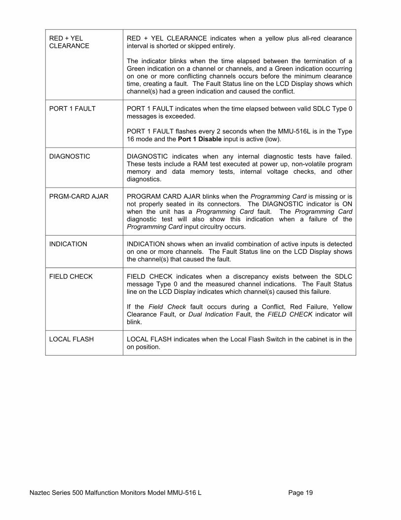
RED + YEL CLEARANCE
RED + YEL CLEARANCE indicates when a yellow plus all-red clearance interval is shorted or skipped entirely. The indicator blinks when the time elapsed between the termination of a Green indication on a channel or channels, and a Green indication occurring on one or more conflicting channels occurs before the minimum clearance time, creating a fault. The Fault Status line on the LCD Display shows which channel(s) had a green indication and caused the conflict.
PORT 1 FAULT PORT 1 FAULT indicates when the time elapsed between valid SDLC Type 0 messages is exceeded. PORT 1 FAULT flashes every 2 seconds when the MMU-516L is in the Type 16 mode and the Port 1 Disable input is active (low).
DIAGNOSTIC DIAGNOSTIC indicates when any internal diagnostic tests have failed. These tests include a RAM test executed at power up, non-volatile program memory and data memory tests, internal voltage checks, and other diagnostics.
PRGM-CARD AJAR PROGRAM CARD AJAR blinks when the Programming Card is missing or is not properly seated in its connectors. The DIAGNOSTIC indicator is ON when the unit has a Programming Card fault. The Programming Card diagnostic test will also show this indication when a failure of the Programming Card input circuitry occurs.
INDICATION INDICATION shows when an invalid combination of active inputs is detected on one or more channels. The Fault Status line on the LCD Display shows the channel(s) that caused the fault.
FIELD CHECK FIELD CHECK indicates when a discrepancy exists between the SDLC message Type 0 and the measured channel indications. The Fault Status line on the LCD Display indicates which channel(s) caused this failure. If the Field Check fault occurs during a Conflict, Red Failure, Yellow Clearance Fault, or Dual Indication Fault, the FIELD CHECK indicator will blink.
LOCAL FLASH LOCAL FLASH indicates when the Local Flash Switch in the cabinet is in the on position.

Naztec Series 500 Malfunction Monitors Model MMU-516 L Page 20
3.2 Channel Status
The MMU-516L provides a Channel Status screen indicating which channels are currently active. Separate rows on the display will show which channels are active with which colors. A channel that senses the Red, Green, Yellow, or Walk input of the channel as active is considered active or “ON” and a corresponding letter will be displayed on the LCD. If the unit has faulted, the Channel Status indicators will display the following:
Fault Condition Channel Status LCD Display
Conflict +24 Volt Input Fault CVM Fault Port 1 Fault External Watchdog Fault
Displays the channels that were active at the time of the fault
Red Fail Short or missing Yellow Clearance Dual Indication Fault
Displays the channel or channels which caused the fault
Minimum Yellow Change plus Red Clearance Failure
Displays the channel or channels that did not meet the minimum clearance time.
Field Check Fault Displays the channel or channels on which the fault occurred. If the MMU-516L is timing a Field Check Status Fault at the time of a Conflict, Red Failure, short or missing Yellow Clearance Failure or Dual Indication Fault, the Field Check LED will blink.
Naztec Series 500 Malfunction Monitors Model MMU-516 L Page 21
4. PROGRAMMING CARD 4.1 Setup
The MMU-516L features are programmed by soldering wire jumpers into the pair of holes associated with each function on the Programming Card. The program card jumpers allow the user to define the permissive channel indications and customize the following functions:
120 Permissive Channel jumper locations 16 Minimum Yellow Change Channel Disable jumper locations 4 Minimum Flash Time jumper locations 24 Volt Latch Enable jumper Controller Voltage Monitor Latch Enable jumper
The Programming Card complies with NEMA TS2-1992 for Malfunction Management Units and is interchangeable with compliant cards from other manufacturers. If the Programming Card is missing or not fully seated in its connector, the MMU-516L will enter the “fault” mode, transfer the Output Relay contacts, illuminate the DIAGNOSTIC LED (constant on), and blink the PRGM-CARD LED. The LCD and keypad can be used to selectively enable and disable the following enhanced features:
Red monitoring inhibit Dual indication Field check Program card fault latching Power disturbances logging Yellow plus green dual indication Red + yellow clearance Minimum Yellow time Red fail less walk CVM logging disable
More information on configuration using the LCD and keypad can be found in section 6.0. 4.2 Permissive Channel Jumpers
The absence of a soldered wire jumper in a Permissive Channel Pair location implies that any combination of signal indications of that channel pair is incompatible and non-permissive. Any two active channels not programmed as permissive result in the Conflict Fault defined in section 2.1.2, Simultaneous indications of Green + Green, Green + Yellow, or Yellow + Yellow on two non-permissive (or conflicting) channel pairs will fault the MMU after 350 milliseconds, activate the Output Relay contacts, and illuminate the CONFLICT LED. For example, to program channels 1 and 5 as permissive on the Programming Card, simply solder a wire jumper in the hole pair at row one, position five.
Naztec Series 500 Malfunction Monitors Model MMU-516 L Page 22
4.3 Minimum Flash Time Jumpers
The Minimum Flash Time controls the duration of “cabinet flash” when power is restored to the terminal facility. The Programming Card provides four jumper hole pairs (labeled b1, b2, b4, and b8), to program the Minimum Flash Time as the summation of the values associated with each jumper (1 Sec., 2 Sec., 4 Sec., and 8 Sec.). One additional second is added to this total to arrive at the Minimum Flash Time. In addition, the Minimum Flash Time cannot be less than 6 seconds. For example, to program a Minimum Flash Time of 7 seconds, solder the jumper positions labeled b2 and b4 for a total of 2 Sec. + 4 Sec. + 1 additional second supplied by the calculation. 4.4 Minimum Yellow Change Channel Disable Jumpers
A Minimum Yellow Change fault occurs when the channel indications move directly from Green to Red (skipped Yellow), or the duration of the Yellow indication is less than the minimum time of 2.7 seconds or the time specified in the minimum yellow configuration screen. The Programming Card provides sixteen jumper hole pairs for disabling the Minimum Yellow Change monitoring for each channel. Minimum Yellow Change monitoring is disabled when a jumper is soldered in that hole pair associated with a channel. 4.5 Latch +24 Volt Fault Jumper
The Programming Card provides a jumper hole pair to enable the latching of +24 Volt DC faults on both of the +24 Volt monitor inputs. 4.6 Latch CVM Fault Jumper
The Programming Card provides a jumper hole pair to enable the latching of Controller Voltage Monitor faults.

Naztec Series 500 Malfunction Monitors Model MMU-516 L Page 23
5. RESET PUSHBUTTON Pressing the Reset Button on the front panel manually resets latched faults. A fault condition may be overridden for a very short time by holding down the Reset Button. However, after 4 seconds, a continuous reset is not recognized until the reset is released and activated again. This reset time-out feature is provided to protect against malfunction or misuse of the monitor Reset Button.
Naztec Series 500 Malfunction Monitors Model MMU-516 L Page 24
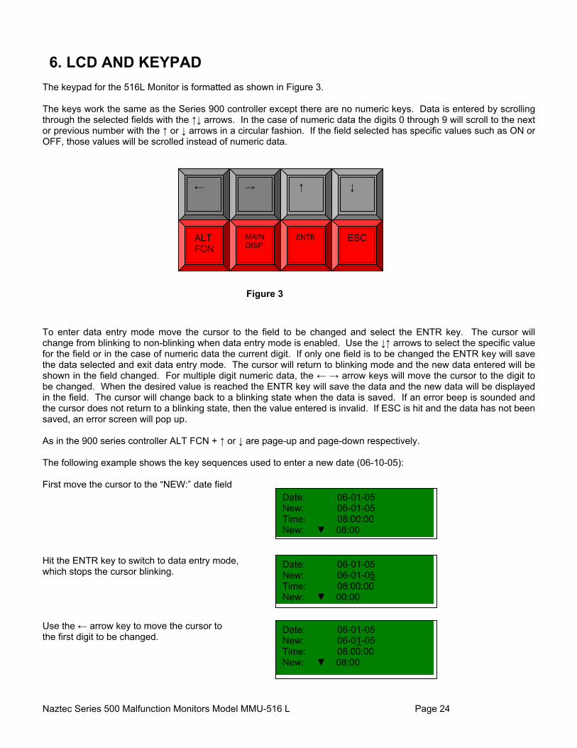
6. LCD AND KEYPAD The keypad for the 516L Monitor is formatted as shown in Figure 3. The keys work the same as the Series 900 controller except there are no numeric keys. Data is entered by scrolling through the selected fields with the ↑↓ arrows. In the case of numeric data the digits 0 through 9 will scroll to the next or previous number with the ↑ or ↓ arrows in a circular fashion. If the field selected has specific values such as ON or OFF, those values will be scrolled instead of numeric data.
Figure 3
To enter data entry mode move the cursor to the field to be changed and select the ENTR key. The cursor will change from blinking to non-blinking when data entry mode is enabled. Use the ↓↑ arrows to select the specific value for the field or in the case of numeric data the current digit. If only one field is to be changed the ENTR key will save the data selected and exit data entry mode. The cursor will return to blinking mode and the new data entered will be shown in the field changed. For multiple digit numeric data, the ← → arrow keys will move the cursor to the digit to be changed. When the desired value is reached the ENTR key will save the data and the new data will be displayed in the field. The cursor will change back to a blinking state when the data is saved. If an error beep is sounded and the cursor does not return to a blinking state, then the value entered is invalid. If ESC is hit and the data has not been saved, an error screen will pop up. As in the 900 series controller ALT FCN + ↑ or ↓ are page-up and page-down respectively. The following example shows the key sequences used to enter a new date (06-10-05): First move the cursor to the “NEW:” date field Hit the ENTR key to switch to data entry mode, which stops the cursor blinking. Use the ← arrow key to move the cursor to the first digit to be changed.
←
→
↓
↑
ALT FCN
MAINDISP
ENTR
ESC
Date: 06-01-05 New: 06-01-05 Time: 08:00:00 New: ▼ 08:00
Date: 06-01-05 New: 06-01-05 Time: 08:00:00 New: ▼ 00:00
Date: 06-01-05 New: 06-01-05 Time: 08:00:00 New: ▼ 08:00
Naztec Series 500 Malfunction Monitors Model MMU-516 L Page 25
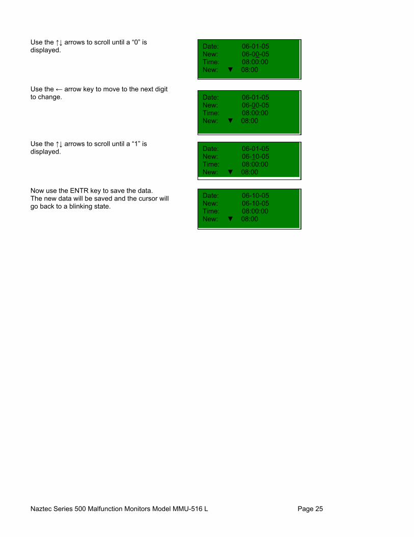
Use the ↑↓ arrows to scroll until a “0” is displayed. Use the ← arrow key to move to the next digit to change. Use the ↑↓ arrows to scroll until a “1” is displayed. Now use the ENTR key to save the data. The new data will be saved and the cursor will go back to a blinking state.
Date: 06-01-05 New: 06-00-05 Time: 08:00:00 New: ▼ 08:00
Date: 06-01-05 New: 06-00-05 Time: 08:00:00 New: ▼ 08:00
Date: 06-01-05 New: 06-10-05 Time: 08:00:00 New: ▼ 08:00
Date: 06-10-05 New: 06-10-05 Time: 08:00:00 New: ▼ 08:00
Naztec Series 500 Malfunction Monitors Model MMU-516 L Page 26
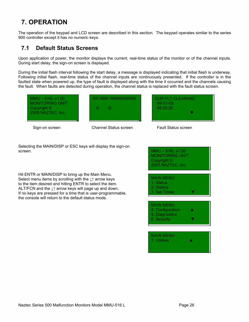
7. OPERATION The operation of the keypad and LCD screen are described in this section. The keypad operates similar to the series 900 controller except it has no numeric keys. 7.1 Default Status Screens
Upon application of power, the monitor displays the current, real-time status of the monitor or of the channel inputs. During start delay, the sign-on screen is displayed. During the initial flash interval following the start delay, a message is displayed indicating that initial flash is underway. Following initial flash, real-time status of the channel inputs are continuously presented. If the controller is in the faulted state when powered up, the type of fault is displayed along with the time it occurred and the channels causing the fault. When faults are detected during operation, the channel status is replaced with the fault status screen.
Sign-on screen Channel Status screen Fault Status screen
Selecting the MAIN/DISP or ESC keys will display the sign-on screen. Hit ENTR or MAIN/DISP to bring up the Main Menu. Select menu items by scrolling with the ↓↑ arrow keys to the item desired and hitting ENTR to select the item. ALT/FCN and the ↓↑ arrow keys will page up and down. If no keys are pressed for a time that is user-programmable, the console will return to the default status mode.
MAIN MENU 7. Utilities ▲
MMU – 516L v1.00 MONITORING UNIT Copyright © 2005 NAZTEC, Inc.
MAIN MENU 1. Status 2. History 3. Set Times ▼
MMU – 516L v1.00 MONITORING UNIT Copyright © 2005 NAZTEC, Inc.
RR RRR RRRRRRRRR G G
CUR FLT CLEARANC 06-01-05 08:00:00 ▼
MAIN MENU 4. Configuration ▲ 5. Diagnostics 6. Security ▼
Naztec Series 500 Malfunction Monitors Model MMU-516 L Page 27
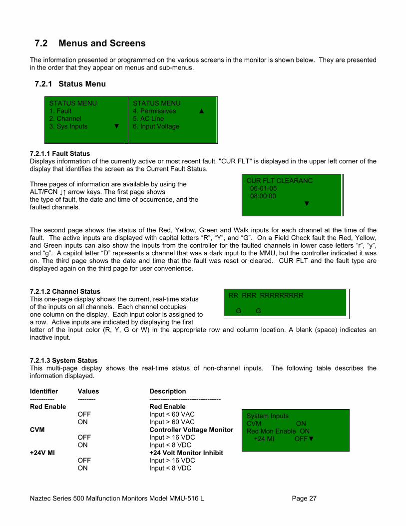
7.2 Menus and Screens
The information presented or programmed on the various screens in the monitor is shown below. They are presented in the order that they appear on menus and sub-menus.
7.2.1 Status Menu 7.2.1.1 Fault Status Displays information of the currently active or most recent fault. "CUR FLT" is displayed in the upper left corner of the display that identifies the screen as the Current Fault Status. Three pages of information are available by using the ALT/FCN ↓↑ arrow keys. The first page shows the type of fault, the date and time of occurrence, and the faulted channels. The second page shows the status of the Red, Yellow, Green and Walk inputs for each channel at the time of the fault. The active inputs are displayed with capital letters “R”, “Y”, and “G”. On a Field Check fault the Red, Yellow, and Green inputs can also show the inputs from the controller for the faulted channels in lower case letters “r”, “y”, and “g”. A capitol letter “D” represents a channel that was a dark input to the MMU, but the controller indicated it was on. The third page shows the date and time that the fault was reset or cleared. CUR FLT and the fault type are displayed again on the third page for user convenience. 7.2.1.2 Channel Status This one-page display shows the current, real-time status of the inputs on all channels. Each channel occupies one column on the display. Each input color is assigned to a row. Active inputs are indicated by displaying the first letter of the input color (R, Y, G or W) in the appropriate row and column location. A blank (space) indicates an inactive input. 7.2.1.3 System Status This multi-page display shows the real-time status of non-channel inputs. The following table describes the information displayed. Identifier Values Description ----------- -------- -------------------------------- Red Enable Red Enable
OFF Input < 60 VAC ON Input > 60 VAC
CVM Controller Voltage Monitor OFF Input > 16 VDC ON Input < 8 VDC
+24V MI +24 Volt Monitor Inhibit OFF Input > 16 VDC ON Input < 8 VDC
STATUS MENU 1. Fault 2. Channel 3. Sys Inputs ▼
STATUS MENU 4. Permissives ▲ 5. AC Line 6. Input Voltage
CUR FLT CLEARANC 06-01-05 08:00:00 ▼
RR RRR RRRRRRRRR G G
System Inputs CVM ON Red Mon Enable ON +24 MI OFF▼

Naztec Series 500 Malfunction Monitors Model MMU-516 L Page 28
7.2.1.4 Permissives The Permissives screen shows the permissives map which was most recently read from the program card. These are the permissives that are used for determining conflict faults. The map is presented in the form of a matrix where each position represents a jumper location on the program card. Each "P" on the display indicates an installed jumper on the program card. 7.2.1.5 AC Line Status The AC line status screen shows the real-time value of the line voltage in AC RMS volts. The range of voltage is from 0 to 135 volts, although the monitor operates on voltages as high as 160 VAC. Also presented is the number of momentary disturbances in AC line voltage detected by the monitor since the last time the monitor was powered up. "Momentary" disturbances include voltage dropouts, dips, surges, and over voltage conditions. These are described in the AC power logging section later in this document. A maximum of 30 disturbances are recorded. 7.2.1.5 Input Voltage The AC input voltage for each color is displayed for the current fault. Data is only valid if there is a current fault.
7.2.2 History Menu
1 PP P 2. PP P P P P 3 . PP P 4 . PP P P P P ▼
AC Line Status Volts RMS 119 Disturbances 1 Cycles 1
HISTORY MENU 1. Fault Log 2. Power Log 3. Print Logs ▼
HISTORY MENU 4. Clear Faults ▲ 5. Clear Power
Ch Grn Yel Red Wlk 1. 0 0 120 0 2. 0 0 120 0 3. ▼ 0 0 120 0

Naztec Series 500 Malfunction Monitors Model MMU-516 L Page 29
7.2.2.1 Fault Log This three-page display shows the same information as the Current Fault Status screen but for previous faults. Up to 20 of the most recent previous faults are stored. The faults are numbered from most recent to oldest with the most recent being assigned number 1. As usual, the ALT/FCN ↓↑ arrow keys are used to move among the various pages of information for each fault. When the fault log is selected from the menu, fault #1 is displayed. Faults are identified as one of the following types:
Fault Type Description ------------- -------------------------- CONFLICT Conflict RED FAIL Red Failure INDICATN Indication Failure
(multiple, invalid indications on a channel) MIN YEL Minimum Yellow MIN GRN Minimum Green SEQ FAIL Sequence Failure (yellow skipped) 24V I +24 Volt DC Monitor #1 24V II +24 Volt DC Monitor #2 CVM Controller Voltage Monitor PRGM CARD Program Card has changed or is ajar YEL+RED CLR Yellow + Red Clearance CLEARANCE Clearance FIELD CHECK Field Check PORT 1 Port 1 SDLC failure LOCAL FLASH Local Flash FIELD CK MON Field Check Monitor
FLT# 1 INDICATN 06-01-05 08:00:00 ▼
F RRRRRRRRRRRRRRRR G
FLT# 1 INDICATN ENDED: 06-01-05 08:00:00
Naztec Series 500 Malfunction Monitors Model MMU-516 L Page 30
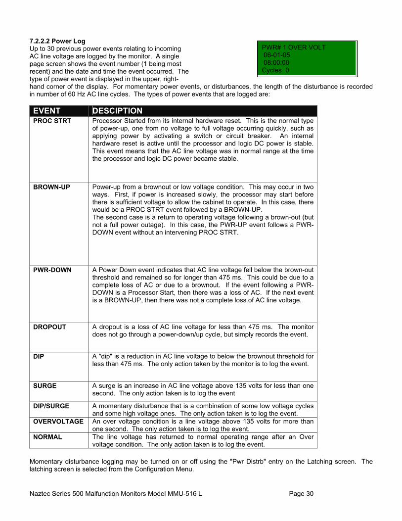
7.2.2.2 Power Log Up to 30 previous power events relating to incoming AC line voltage are logged by the monitor. A single page screen shows the event number (1 being most recent) and the date and time the event occurred. The type of power event is displayed in the upper, right- hand corner of the display. For momentary power events, or disturbances, the length of the disturbance is recorded in number of 60 Hz AC line cycles. The types of power events that are logged are: EVENT DESCIPTION PROC STRT Processor Started from its internal hardware reset. This is the normal type
of power-up, one from no voltage to full voltage occurring quickly, such as applying power by activating a switch or circuit breaker. An internal hardware reset is active until the processor and logic DC power is stable. This event means that the AC line voltage was in normal range at the time the processor and logic DC power became stable.
BROWN-UP Power-up from a brownout or low voltage condition. This may occur in two ways. First, if power is increased slowly, the processor may start before there is sufficient voltage to allow the cabinet to operate. In this case, there would be a PROC STRT event followed by a BROWN-UP. The second case is a return to operating voltage following a brown-out (but not a full power outage). In this case, the PWR-UP event follows a PWR-DOWN event without an intervening PROC STRT.
PWR-DOWN A Power Down event indicates that AC line voltage fell below the brown-out threshold and remained so for longer than 475 ms. This could be due to a complete loss of AC or due to a brownout. If the event following a PWR-DOWN is a Processor Start, then there was a loss of AC. If the next event is a BROWN-UP, then there was not a complete loss of AC line voltage.
DROPOUT A dropout is a loss of AC line voltage for less than 475 ms. The monitor does not go through a power-down/up cycle, but simply records the event.
DIP A "dip" is a reduction in AC line voltage to below the brownout threshold for less than 475 ms. The only action taken by the monitor is to log the event.
SURGE A surge is an increase in AC line voltage above 135 volts for less than one second. The only action taken is to log the event
DIP/SURGE A momentary disturbance that is a combination of some low voltage cycles and some high voltage ones. The only action taken is to log the event.
OVERVOLTAGE An over voltage condition is a line voltage above 135 volts for more than one second. The only action taken is to log the event.
NORMAL The line voltage has returned to normal operating range after an Over voltage condition. The only action taken is to log the event.
Momentary disturbance logging may be turned on or off using the "Pwr Distrb" entry on the Latching screen. The latching screen is selected from the Configuration Menu.
PWR# 1 OVER VOLT 06-01-05 08:00:00 Cycles 0

Naztec Series 500 Malfunction Monitors Model MMU-516 L Page 31
7.2.2.3 Print Logs This screen is used to print reports to an attached printer. There are four reports available that may be printed singly or in two combinations. The print selections that are available are as follows: Selection Report(s) Description --------- ------------- ------------------------- CONFIG Configuration All operator programmable entry screens and program card permissives HISTRY History Fault Log and Power Log TRACE Trace Log FAULT Fault Log POWER Power Log ALL All Reports Configuration, Fault, Power, Trace Reports 7.2.2.4 Clear Faults The fault log may be cleared of all stored faults or uninitialized data by using this screen. 7.2.2.5 Clear Power The power log may be cleared of all stored power events or uninitialized data by using this screen. 7.2.3 Set Times Menu 7.2.3.1 Date/Time The date and time are set using this screen. When setting either of these values, leading zeros must be entered. The Date is entered in a single, six-digit field (dashes are not entered). A four-digit field is provided to enter hours and minutes for setting the time. The seconds field of the time is automatically set to 00 at the instant the ENTR key is pressed. This feature allows setting the time to within one second of the desired time by waiting until the "top of the minute" before pressing the ENTR key. 7.2.3.2 Flash Delay The flash delay is programmable from 6 to 16 seconds in second increments. This is programmed by soldered jumpers on the Program Card. This screen is used only to view the setting.
Select Group to Print: CONFIG Press ESC when done.
Press Enter to Clear the Fault Log … In-Progress…
Press Enter to Clear the Power Log … Complete.
SET TIMES MENU 1. Date/Time 2. Flash Delay 3. Daylight Save
Date: 06-01-05 New: 00-00-00 Time: 08:00:00 New: ▼ 00:00
Time: ▲ 08:00:00 New: 00:00 Day: MON New:
Flash Delay Time: 6.0
Naztec Series 500 Malfunction Monitors Model MMU-516 L Page 32
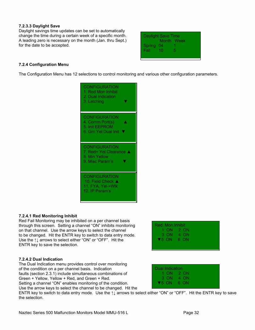
7.2.3.3 Daylight Save Daylight savings time updates can be set to automatically change the time during a certain week of a specific month. A leading zero is necessary on the month (Jan. thru Sept.) for the date to be accepted. 7.2.4 Configuration Menu The Configuration Menu has 12 selections to control monitoring and various other configuration parameters. 7.2.4.1 Red Monitoring Inhibit Red Fail Monitoring may be inhibited on a per channel basis through this screen. Setting a channel “ON” inhibits monitoring on that channel. Use the arrow keys to select the channel to be changed. Hit the ENTR key to switch to data entry mode. Use the ↑↓ arrows to select either “ON” or “OFF”. Hit the ENTR key to save the selection. 7.2.4.2 Dual Indication The Dual Indication menu provides control over monitoring of the condition on a per channel basis. Indication faults (section 2.3.1) include simultaneous combinations of Green + Yellow, Yellow + Red, and Green + Red. Setting a channel “ON” enables monitoring of the condition. Use the arrow keys to select the channel to be changed. Hit the ENTR key to switch to data entry mode. Use the ↑↓ arrows to select either “ON” or “OFF”. Hit the ENTR key to save the selection.
Daylight Save Time Month Week Spring 04 1 Fall 10 5
CONFIGURATION 1. Red Mon Inhibit 2. Dual Indication 3. Latching ▼
CONFIGURATION 4. Comm Port(s) ▲ 5. Init EEPROM 6. Grn Yel Dual Ind ▼
CONFIGURATION 7. Red+ Yel Clearance ▲ 8. Min Yellow 9. Misc Param’s ▼
Red. Mon.Inhibit 1 ON 2 ON 3 ON 4 ON ▼5 ON 6 ON
Dual Indication 1 ON 2 ON 3 ON 4 ON ▼5 ON 6 ON
CONFIGURATION 10. Field Check ▲ 11. FYA, Yel->Wlk 12. IP Param’s
Naztec Series 500 Malfunction Monitors Model MMU-516 L Page 33
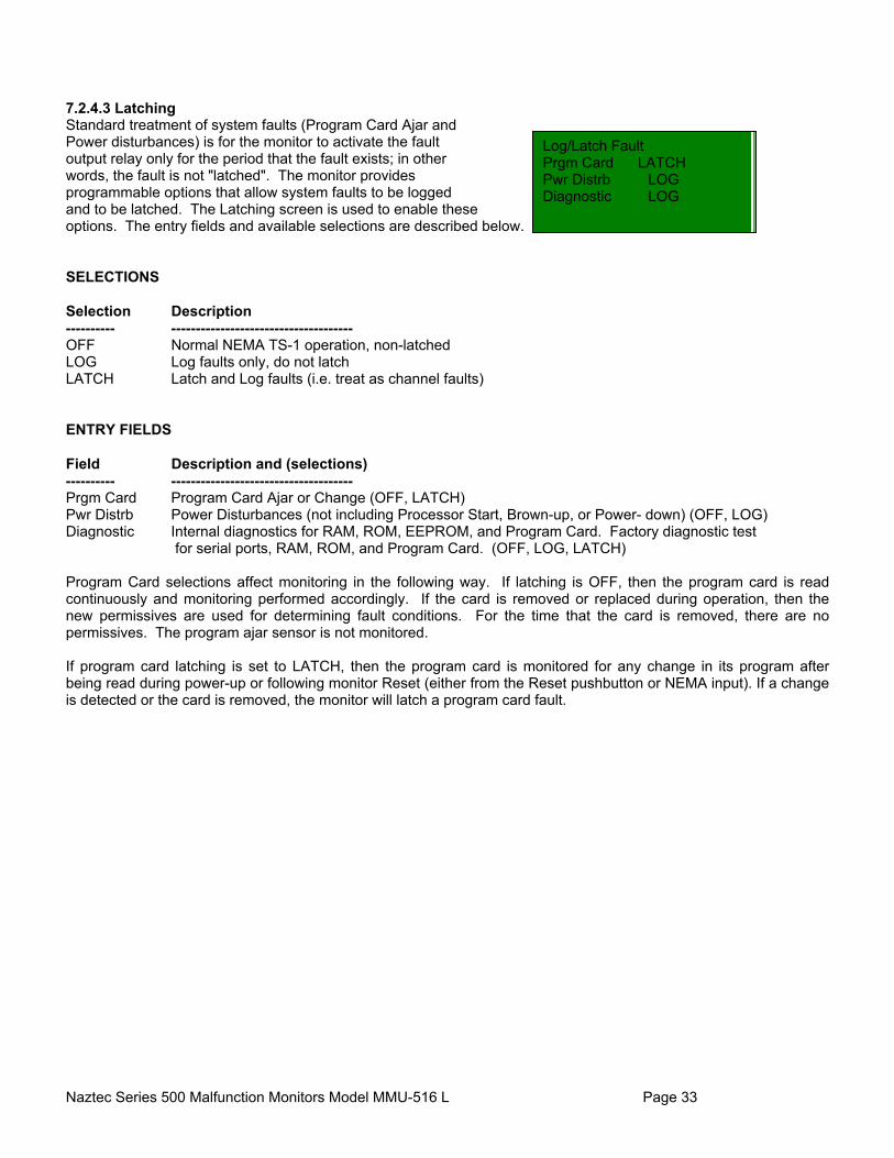
7.2.4.3 Latching Standard treatment of system faults (Program Card Ajar and Power disturbances) is for the monitor to activate the fault output relay only for the period that the fault exists; in other words, the fault is not "latched". The monitor provides programmable options that allow system faults to be logged and to be latched. The Latching screen is used to enable these options. The entry fields and available selections are described below. SELECTIONS Selection Description ---------- ------------------------------------- OFF Normal NEMA TS-1 operation, non-latched LOG Log faults only, do not latch LATCH Latch and Log faults (i.e. treat as channel faults) ENTRY FIELDS Field Description and (selections) ---------- ------------------------------------- Prgm Card Program Card Ajar or Change (OFF, LATCH) Pwr Distrb Power Disturbances (not including Processor Start, Brown-up, or Power- down) (OFF, LOG) Diagnostic Internal diagnostics for RAM, ROM, EEPROM, and Program Card. Factory diagnostic test
for serial ports, RAM, ROM, and Program Card. (OFF, LOG, LATCH) Program Card selections affect monitoring in the following way. If latching is OFF, then the program card is read continuously and monitoring performed accordingly. If the card is removed or replaced during operation, then the new permissives are used for determining fault conditions. For the time that the card is removed, there are no permissives. The program ajar sensor is not monitored. If program card latching is set to LATCH, then the program card is monitored for any change in its program after being read during power-up or following monitor Reset (either from the Reset pushbutton or NEMA input). If a change is detected or the card is removed, the monitor will latch a program card fault.
Log/Latch Fault Prgm Card LATCH Pwr Distrb LOG Diagnostic LOG
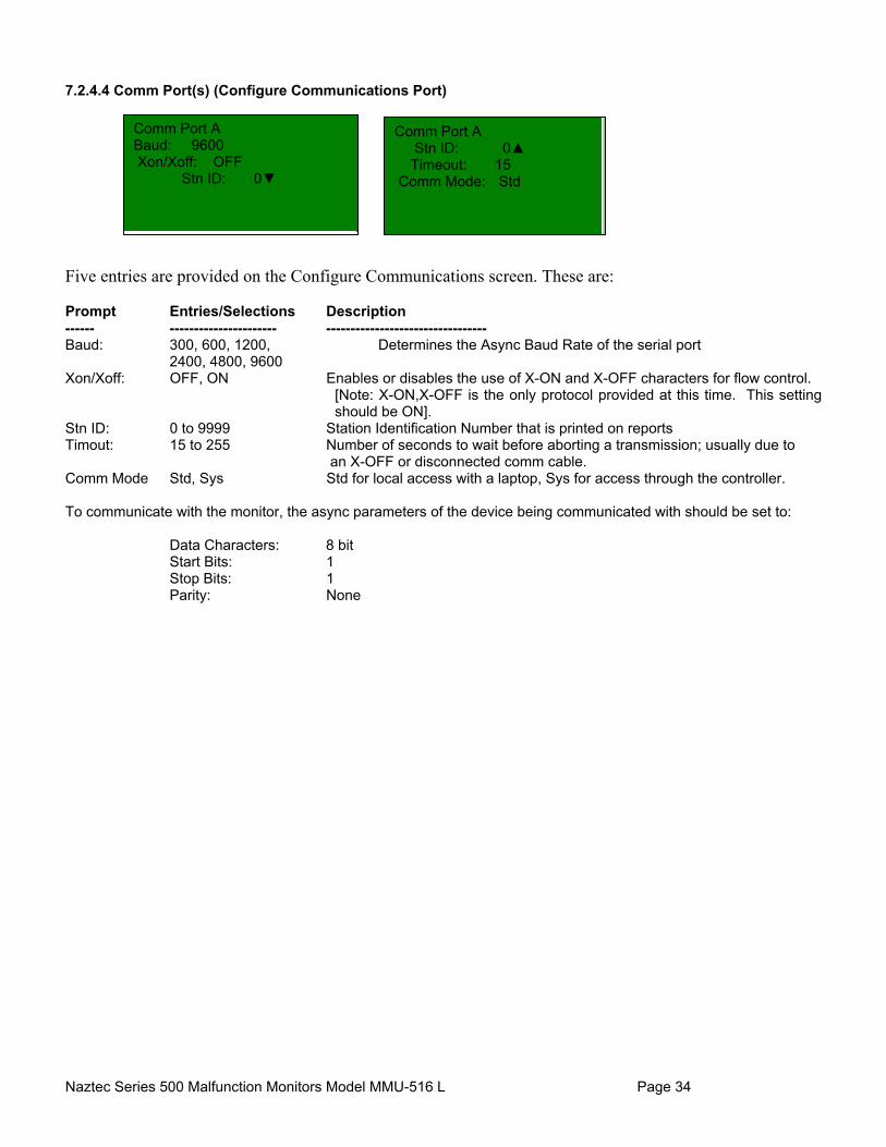
Naztec Series 500 Malfunction Monitors Model MMU-516 L Page 34
7.2.4.4 Comm Port(s) (Configure Communications Port) Five entries are provided on the Configure Communications screen. These are: Prompt Entries/Selections Description ------ ---------------------- --------------------------------- Baud: 300, 600, 1200, Determines the Async Baud Rate of the serial port
2400, 4800, 9600 Xon/Xoff: OFF, ON Enables or disables the use of X-ON and X-OFF characters for flow control.
[Note: X-ON,X-OFF is the only protocol provided at this time. This setting should be ON].
Stn ID: 0 to 9999 Station Identification Number that is printed on reports Timout: 15 to 255 Number of seconds to wait before aborting a transmission; usually due to
an X-OFF or disconnected comm cable. Comm Mode Std, Sys Std for local access with a laptop, Sys for access through the controller. To communicate with the monitor, the async parameters of the device being communicated with should be set to:
Data Characters: 8 bit Start Bits: 1 Stop Bits: 1 Parity: None
Comm Port A Baud: 9600 Xon/Xoff: OFF Stn ID: 0▼
Comm Port A Stn ID: 0▲ Timeout: 15 Comm Mode: Std

Naztec Series 500 Malfunction Monitors Model MMU-516 L Page 35
7.2.4.5 Init EEPROM The default settings of all configuration parameters that are stored in non-volatile memory (EEPROM) may be restored to their factory settings using this screen. The default values are: Parameter Default Setting ----------------------------- --------------------------------------- Min Yellow 2.7 seconds, all channels Red Fail Monitor Inhibit OFF, all channels Enabled Dual Indication Monitoring ON, all channels Green + Yellow Dual Indication ON, all channels Field Check Enable ON, all channels Red Fail Less Walk OFF Red + Yellow Clearance ON System Fault Latching LOG for CVM, 24V I & II; OFF for Program Card Power Disturbance Logging OFF Console timeout 2 min. Tone Enable ON Comm Baud 9600 Xon/Xoff OFF Station ID 0 Timeout 30 Seconds Comm mode System Security Codes None entered Access Levels None, all users Diagnostic Latching LATCH 7.2.4.6 Green and Yellow Dual Indication The MMU-516L provides Green & Yellow Dual Indication Enable control on a per channel basis. These selections enable green & yellow Dual Indication monitoring separately for all 16 channels regardless of the settings for Field Check/Dual Indication Channel monitoring. Setting a channel “ON” enables monitoring. 7.2.4.7 Red Plus Yellow Clearance Controls whether the Minimum Yellow Change Channel Disable jumper on the program card for each channel controls the Minimum Yellow plus Red Clearance testing. When this selection is in the “ON” position, both the Minimum Yellow and the Minimum Yellow plus Red Clearance tests are controlled by MYCCD jumpers on the Programming Card. When it is “OFF”, only the Minimum Yellow testing is controlled by the MYCCD jumpers.
Grn Yel Dual Ind 1 ON 2 ON 3 ON 4 ON ▼5 ON 6 ON
Red+Yel Clearance Enable: ON
Press Enter to Restore Default Program …
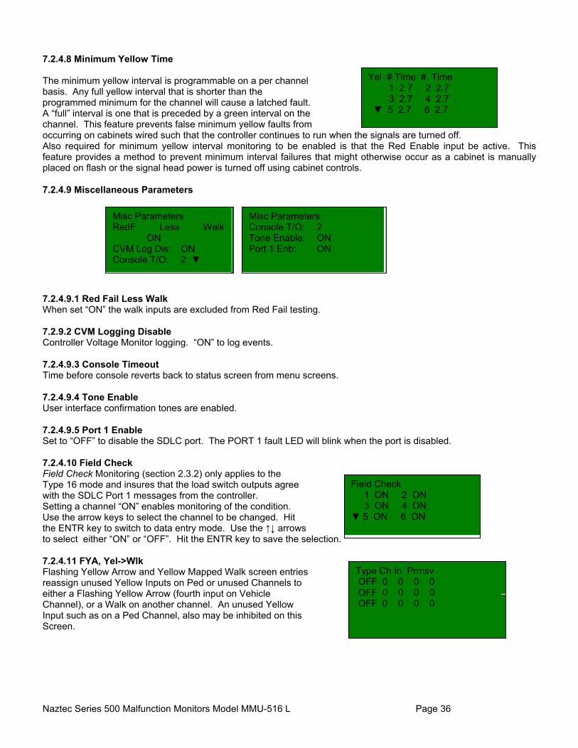
Naztec Series 500 Malfunction Monitors Model MMU-516 L Page 36
7.2.4.8 Minimum Yellow Time The minimum yellow interval is programmable on a per channel basis. Any full yellow interval that is shorter than the programmed minimum for the channel will cause a latched fault. A “full” interval is one that is preceded by a green interval on the channel. This feature prevents false minimum yellow faults from occurring on cabinets wired such that the controller continues to run when the signals are turned off. Also required for minimum yellow interval monitoring to be enabled is that the Red Enable input be active. This feature provides a method to prevent minimum interval failures that might otherwise occur as a cabinet is manually placed on flash or the signal head power is turned off using cabinet controls. 7.2.4.9 Miscellaneous Parameters 7.2.4.9.1 Red Fail Less Walk When set “ON” the walk inputs are excluded from Red Fail testing. 7.2.9.2 CVM Logging Disable Controller Voltage Monitor logging. “ON” to log events. 7.2.4.9.3 Console Timeout Time before console reverts back to status screen from menu screens. 7.2.4.9.4 Tone Enable User interface confirmation tones are enabled. 7.2.4.9.5 Port 1 Enable Set to “OFF” to disable the SDLC port. The PORT 1 fault LED will blink when the port is disabled. 7.2.4.10 Field Check Field Check Monitoring (section 2.3.2) only applies to the Type 16 mode and insures that the load switch outputs agree with the SDLC Port 1 messages from the controller. Setting a channel “ON” enables monitoring of the condition. Use the arrow keys to select the channel to be changed. Hit the ENTR key to switch to data entry mode. Use the ↑↓ arrows to select either “ON” or “OFF”. Hit the ENTR key to save the selection. 7.2.4.11 FYA, Yel->Wlk Flashing Yellow Arrow and Yellow Mapped Walk screen entries reassign unused Yellow Inputs on Ped or unused Channels to either a Flashing Yellow Arrow (fourth input on Vehicle Channel), or a Walk on another channel. An unused Yellow Input such as on a Ped Channel, also may be inhibited on this Screen.
Yel #.Time #. Time 1 2.7 2 2.7 3 2.7 4 2.7 ▼ 5 2.7 6 2.7
Misc Parameters RedF Less Walk: ON CVM Log Dis: ON Console T/O: 2 ▼
Misc Parameters Console T/O: 2 Tone Enable: ON Port 1 Enb: ON
Field Check 1 ON 2 ON 3 ON 4 ON ▼ 5 ON 6 ON
Type Ch In Prmsv OFF 0 0 0 0 OFF 0 0 0 0 OFF 0 0 0 0
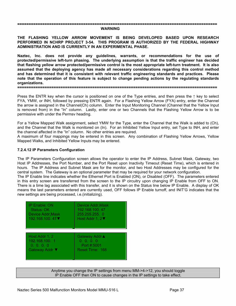
Naztec Series 500 Malfunction Monitors Model MMU-516 L Page 37
========================================================================================
WARNING THE FLASHING YELLOW ARROW MOVEMENT IS BEING DEVELOPED BASED UPON RESEARCH PERFORMED IN NCHRP PROJECT 3-54. THIS PROGRAM IS AUTHORIZED BY THE FEDERAL HIGHWAY ADMINISTRATION AND IS CURRENTLY IN AN EXPERIMENTAL PHASE. Naztec, Inc. does not provide any guidelines, warrants, or recommendations for the use of protected/permissive left-turn phasing. The underlying assumption is that the traffic engineer has decided that flashing yellow arrow protected/permissive control is the most appropriate left-turn treatment. It is also assumed that the deploying agency has made all necessary considerations regarding this control method and has determined that it is consistent with relevant traffic engineering standards and practices. Please note that the operation of this feature is subject to change pending actions by the regulating standards organizations. ======================================================================================== Press the ENTR key when the cursor is positioned on one of the Type entries, and then press the ↑ key to select FYA, YMW, or INH, followed by pressing ENTR again. For a Flashing Yellow Arrow (FYA) entry, enter the Channel the arrow is assigned in the Channel(Ch) column. Enter the Input Monitoring Channel (Channel that the Yellow Input is removed from) in the “In” column. Lastly, enter one or two Channels that the Flashing Yellow Arrow is to be permissive with under the Permsv heading. For a Yellow Mapped Walk assignment, select YMW for the Type, enter the Channel that the Walk is added to (Ch), and the Channel that the Walk is monitored on (In). For an Inhibited Yellow Input entry, set Type to INH, and enter the channel affected in the “In” column. No other entries are required. A maximum of four mappings may be entered in this screen. Any combination of Flashing Yellow Arrows, Yellow Mapped Walks, and Inhibited Yellow Inputs may be entered. 7.2.4.12 IP Parameters Configuration The IP Parameters Configuration screen allows the operator to enter the IP Address, Subnet Mask, Gateway, two Host IP Addresses, the Port Number, and the Port Reset upon Inactivity Timeout (Reset Time), which is entered in hours. The IP Address and Subnet Mask are for the monitor, and two Host Addresses may be configured for the central system. The Gateway is an optional parameter that may be required for your network configuration. The IP Enable line indicates whether the Ethernet Port is Enabled (ON), or Disabled (OFF). The parameters entered in this entry screen are transferred from the screen to the IP circuitry upon changing IP Enable from OFF to ON. There is a time lag associated with this transfer, and it is shown on the Status line below IP Enable. A display of OK means the last parameters entered are currently used, OFF follows IP Enable turnoff, and INIT’G indicates that the new settings are being processed, i.e.(initializing).
Anytime you change the IP settings from menu MM->4->12, you should toggle IP Enable OFF then ON to cause changes in the IP settings to take effect.
IP Enable: ON Status: OK Device Addr,Mask 192.168.100. 47▼
Device Addr,Mask 192.168.100. 47 255.255.255. 0 Host Addr 1, 2▼
Host Addr 1, 2 192.168.100. 1 0. 0. 0. 0 Gateway Addr ▼
Gateway Addr▲ 0. 0. 0. 0 Port #:5001 Reset Time: 168

Naztec Series 500 Malfunction Monitors Model MMU-516 L Page 38
7.2.5 Diagnostics Menu NOTE: Diagnostics can be disruptive and are meant to be used for production testing. Latching and Logging of the test results can be controlled through the Diagnostic latch in the configuration menu under latching. 7.2.5.1 RAM Memory The RAM diagnostic verifies that all RAM locations may be written and read with a variety of data patterns. Change the Run Mode to either “ONCE” or “CONT” to perform the tests. The status field will display PASSED or FAILED on completion of the tests. 7.2.5.2 ROM Memory The ROM diagnostic calculates a checksum of the entire program memory. The result of the checksum is displayed as PASSED or FAILED. The calculated checksum is also displayed. 7.2.5.3 Program Card This factory diagnostic uses an external test fixture to verify that each input of the program card slot is functioning and that there are no short circuits between any of them. It is a production-time diagnostic. 7.2.5.4 Permissives The Permissives screen shows the permissives map which was most recently read from the program card. These are the permissives used for determining conflict faults. This screen may also be used with multiple program cards to verify that the program card slot is functioning properly. When used in this way, four or more cards should be used, each with a different set of program jumpers installed. The jumpers on any card should be equally spaced; for example, every fourth jumper if four cards are used, or every fifth if there are five cards. If all cards are read properly, it is unlikely that the program card circuitry is malfunctioning. The more cards that are used (with fewer jumpers installed per card), the less likely it will be that an error goes undetected. 7.2.5.5 Serial Port Use this screen and a "loopback" connector to execute the internal self-test of the serial port. The loopback connector should be wired with pins 1 and 4, 2 and 3, and 7 and 8 connected in pairs. To execute the self-test, install the loopback connector on the port to be tested. Then select the port and test to be run below the prompt "Sel Test:". The status will be displayed during the test and the results when it is complete. If "PORT 2 CONT" is selected, the test will be run continuously. In this case, a successful test is one that continues to
DIAGNOSTICS 1. RAM Memory 2. ROM Memory 3. Program Card ▼
RAM Diagnostic Run Mode: NONE Status: PASSED
ROM Diagnostic Press Enter… Status: PASSED Checksum: 0000
Press ENTR to Test Program Card Slot … 0
Sel Test: PORT 2 ONCE Status: TEST COMPLETE
1 PP P 2. PP P P P P 3 . PP P 4 . PP P P P P ▼
DIAGNOSTICS 4. Permissives ▲ 5. Serial Port 6. LEDs

Naztec Series 500 Malfunction Monitors Model MMU-516 L Page 39
display a status of "RUNNING". If the "PORT 2 ONCE" test is selected, a successful test displays "TEST COMPLETE". An unsuccessful test will result in one of the following messages: TRANSMIT ERROR, RECEIVE ERROR, TIMEOUT ERROR or MESSAGE ERROR. Setting the Console Timeout value to 255 will prevent the status screen from over-writing the test screen. 7.2.5.6 LEDs The LEDs on the display board will cycle through one at a time. Once the test is done, the display will be updated to show a complete status. Hit ESC to exit test or ENTR to restart.
LED Test: Hit ENTR to start Complete
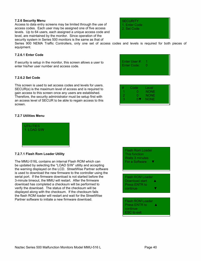
Naztec Series 500 Malfunction Monitors Model MMU-516 L Page 40
7.2.6 Security Menu Access to data entry screens may be limited through the use of access codes. Each user may be assigned one of five access levels. Up to 64 users, each assigned a unique access code and level, are maintained by the monitor. Since operation of the security system in Series 500 monitors is the same as that of Series 900 NEMA Traffic Controllers, only one set of access codes and levels is required for both pieces of equipment. 7.2.6.1 Enter Code If security is setup in the monitor, this screen allows a user to enter his/her user number and access code. 7.2.6.2 Set Code This screen is used to set access codes and levels for users. SECUR(e) is the maximum level of access and is required to gain access to this screen once any users are established. Therefore, the security administrator must be setup first with an access level of SECUR to be able to regain access to this screen. 7.2.7 Utilities Menu 7.2.7.1 Flash Rom Loader Utility The MMU-516L contains an internal Flash ROM which can be updated by selecting the “LOAD S/W” utility and accepting the warning displayed on the LCD. StreetWise Partner software is used to download the new firmware to the controller using the serial port. If the firmware download is not started before the 3-minute timeout, the MMU will restart. After the firmware download has completed a checksum will be performed to verify the download. The status of the checksum will be displayed along with the checksum. If the checksum fails the flash ROM loader will restart and wait for the StreetWise Partner software to initiate a new firmware download.
SECURITY 1. Enter Code 2. Set Code
UTILITIES 1. LOAD S/W
Enter User #: 1 Enter Code: 0
# Code Level 1 0 NONE 2 0 NONE 3 0▼ NONE
Flash Rom Loader This function Waits 3 minutes For a Software ▼
Flash ROM Loader Download start ▲ Press ENTR to continue ▼
Flash ROM Loader Press ENTR to ▲ continue ESC to exit
Naztec Series 500 Malfunction Monitors Model MMU-516 L Page 41
8. REMOTE/LOCAL ACCESS WITH DATA PORT 2 The MMU-516L communications Port 2 allows data logs stored within the MMU to be uploaded to a field device (laptop computer) or through the system which is interfaced to the controller. This section provides a review of the various data logs generated by the monitor that record fault conditions and power interruptions. 8.1 Data Port 2 Interface
The MMU-516L provides an asynchronous EIA-232 data port (Port 2) operating at 300 to 19,200 Baud with one start bit, one stop bit, 8 data bits and no parity. The data port interfaces the MMU with the system or a laptop computer running a terminal program. A ‘null modem’ cable connects these devices. The date and time stored in the MMU-516L may be updated manually from the keyboard or from an external computer connected to Port 2. Time and date is automatically updated if Port 2 of the MMU-516L is interfaced with the Aux-232 port of the controller. Date and time is also automatically updated in a Type 16 (TS2 type 1) configuration when the monitor receives a Type 9 SDLC message from the controller. 8.2 Remote Access
The MMU-516L forwards internal data logs and reports based on a request message issued by an external device over Port 2. The Comm Mode should be set to Sys (System) Mode to allow the MMU-516L to respond to these requests The following remote requests consist of an escape sequence of four characters. Command Sequence Description ESC X ESC 1 Programming Report Request
ESC X ESC 2 History Report Request (Fault and Power Log Reports) ESC X ESC 3 Trace Report Request ESC X ESC 4 Fault Report Request ESC X ESC 5 Power Report Request ESC X ESC 6 All Reports Request ESC X ESC 7 Present Fault Report Request ESC X ESC F Present Fault Report Request ESC X ESC I Analyzer (Trace) Report Request ESC X ESC R History Report Request The monitor also accepts a date & time message of 10 characters from the controller Aux-232 port in the following format: tenths of seconds, seconds, minutes, hour, day of week, day of month, month, year. The device issuing the report request may use flow control characters DC1 (X-ON) and DC3 (X-OFF) to divide the report into segments if required because of device limitations.
Naztec Series 500 Malfunction Monitors Model MMU-516 L Page 42
8.3 Help Menu
The MMU-516L Help Menu is accessed by typing [H], [M], or [HM] followed by the [ENTER] or [RETURN] key. Be sure to have the Comm Mode set to “Std” (Standard Mode). The Help Menu is: HELP MENU Command Format followed by [Enter] Code HELP MENU HM Set Station # SS NNN Set Location LO description of location Set Day of Week SW W (1=Sun thru 7=Sat) Set Daylight Savings Time SF SM,SW,FM,FW (spring month, week of month, fall month, week of month) Programming PR Set Date SD MM DD YY Set Time ST HH : MM Present Fault PF Fault Log FL Power Log PL Trace Log TR Fault&Power Log FP All Logs AL Voltmeter VM Clear Fault Log CF Clear Power Log CP The following notes and examples should explain the data fields: NNN a three digit number from 0 to 999 Description of location a text string of 36 or less characters i.e. LO Main Street @ Second Avenue MM DD YY numeric month day year i.e. June 8, 2000 enter SD 06 08 00 or SD 6 8 00 ST HH:MM numeric hour minute i.e. 2:40 PM so enter ST 14:40 8.4 Reports
The following reports are available from the MMU-516L:
Programming Report (Programming Card jumpers and switch settings) Power Log Report (all AC Power line disturbances and anomalies) Fault Log Report (current fault and any previous faults) Trace Log Report (status of all inputs to the monitor during a fault)
8.4.1 Programming Report
The Programming Report provides the current jumper status on the Programming Card:
Permissive Channel pair jumpers Minimum Yellow Change Channel Disable jumpers Initial Flash Delay Time jumpers CVM jumper +24 Volt Latch Fault jumpers
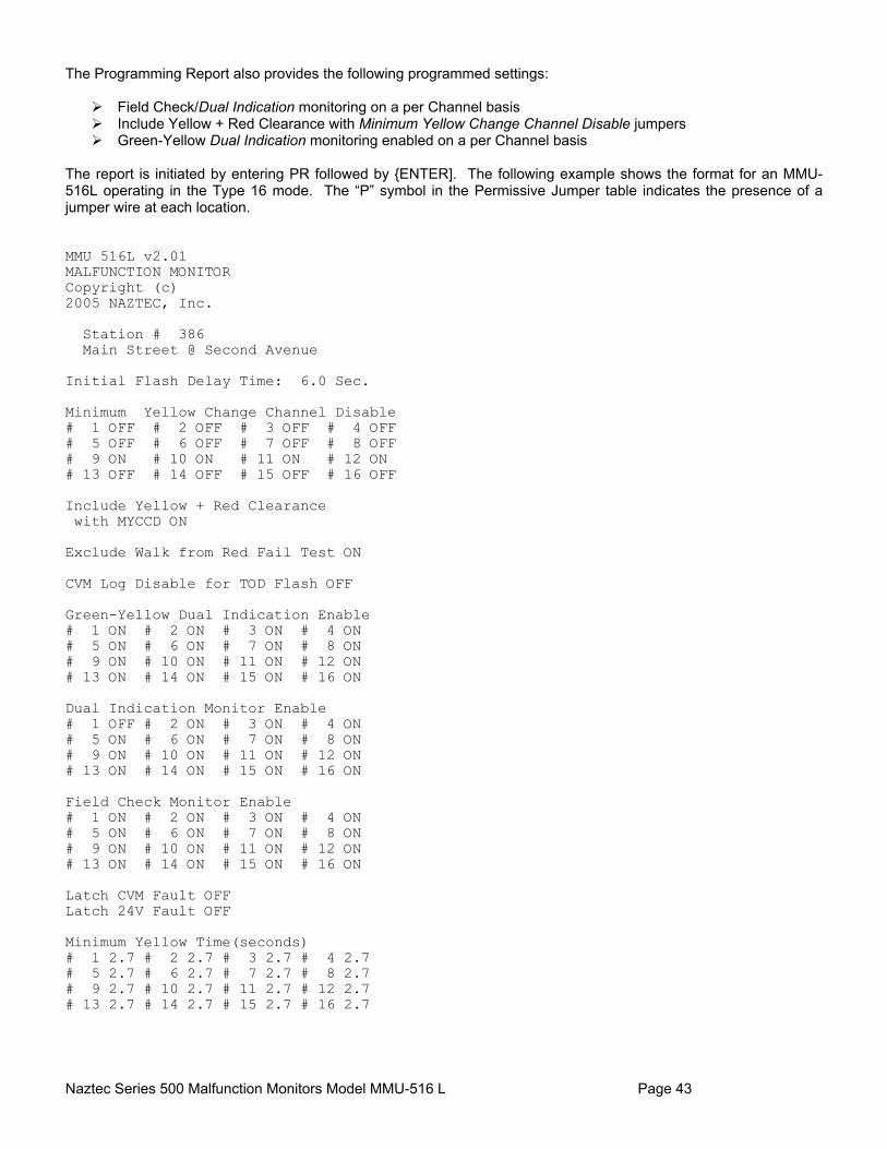
Naztec Series 500 Malfunction Monitors Model MMU-516 L Page 43
The Programming Report also provides the following programmed settings:
Field Check/Dual Indication monitoring on a per Channel basis Include Yellow + Red Clearance with Minimum Yellow Change Channel Disable jumpers Green-Yellow Dual Indication monitoring enabled on a per Channel basis
The report is initiated by entering PR followed by {ENTER]. The following example shows the format for an MMU-516L operating in the Type 16 mode. The “P” symbol in the Permissive Jumper table indicates the presence of a jumper wire at each location. MMU 516L v2.01 MALFUNCTION MONITOR Copyright (c) 2005 NAZTEC, Inc. Station # 386 Main Street @ Second Avenue Initial Flash Delay Time: 6.0 Sec. Minimum Yellow Change Channel Disable # 1 OFF # 2 OFF # 3 OFF # 4 OFF # 5 OFF # 6 OFF # 7 OFF # 8 OFF # 9 ON # 10 ON # 11 ON # 12 ON # 13 OFF # 14 OFF # 15 OFF # 16 OFF Include Yellow + Red Clearance with MYCCD ON Exclude Walk from Red Fail Test ON CVM Log Disable for TOD Flash OFF Green-Yellow Dual Indication Enable # 1 ON # 2 ON # 3 ON # 4 ON # 5 ON # 6 ON # 7 ON # 8 ON # 9 ON # 10 ON # 11 ON # 12 ON # 13 ON # 14 ON # 15 ON # 16 ON Dual Indication Monitor Enable # 1 OFF # 2 ON # 3 ON # 4 ON # 5 ON # 6 ON # 7 ON # 8 ON # 9 ON # 10 ON # 11 ON # 12 ON # 13 ON # 14 ON # 15 ON # 16 ON Field Check Monitor Enable # 1 ON # 2 ON # 3 ON # 4 ON # 5 ON # 6 ON # 7 ON # 8 ON # 9 ON # 10 ON # 11 ON # 12 ON # 13 ON # 14 ON # 15 ON # 16 ON Latch CVM Fault OFF Latch 24V Fault OFF Minimum Yellow Time(seconds) # 1 2.7 # 2 2.7 # 3 2.7 # 4 2.7 # 5 2.7 # 6 2.7 # 7 2.7 # 8 2.7 # 9 2.7 # 10 2.7 # 11 2.7 # 12 2.7 # 13 2.7 # 14 2.7 # 15 2.7 # 16 2.7
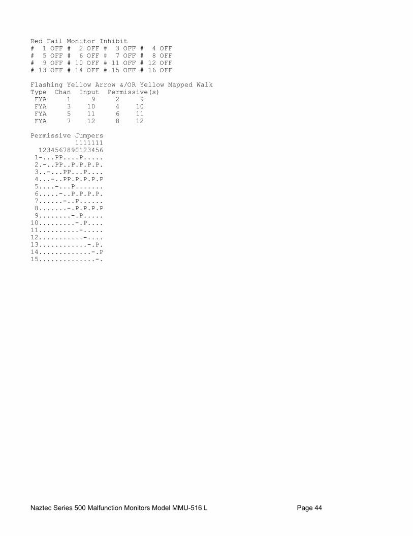
Naztec Series 500 Malfunction Monitors Model MMU-516 L Page 44
Red Fail Monitor Inhibit # 1 OFF # 2 OFF # 3 OFF # 4 OFF # 5 OFF # 6 OFF # 7 OFF # 8 OFF # 9 OFF # 10 OFF # 11 OFF # 12 OFF # 13 OFF # 14 OFF # 15 OFF # 16 OFF Flashing Yellow Arrow &/OR Yellow Mapped Walk Type Chan Input Permissive(s) FYA 1 9 2 9 FYA 3 10 4 10 FYA 5 11 6 11 FYA 7 12 8 12 Permissive Jumpers 1111111 1234567890123456 1-...PP....P..... 2.-..PP..P.P.P.P. 3..-...PP...P.... 4...-..PP.P.P.P.P 5....-...P....... 6.....-..P.P.P.P. 7......-..P...... 8.......-.P.P.P.P 9........-.P..... 10.........-.P.... 11..........-..... 12...........-.... 13............-.P. 14.............-.P 15..............-.

Naztec Series 500 Malfunction Monitors Model MMU-516 L Page 45
8.4.2 Power Log Report The MMU-516L Power Log Report stores the last 30 power line disturbances and records the type of power event and the date and time the even occurred. Power line disturbances are typically very short in duration, so the length of each disturbance is recorded in the number of 60 Hz AC line cycles. The types of power events that are logged are: PROC START This event records when the processor initializes after an internal hardware
reset or after power is restored. Normal power is restored from a no voltage condition to a full voltage condition (power activated by a switch or circuit breaker). An internal hardware reset is active until the processor +5 VDC power becomes stable. This event records when the AC line voltage was in the normal operating range at the time the processor and logic DC power within the MMU becomes stable.
BROWN-UP This event records when power is restored after a brownout or low voltage condition. This may occur in two ways. First, if power is increased slowly, the processor may start before there is sufficient voltage to allow the cabinet to operate. In this case, there would be a PROC START event followed by a BROWN-UP. The second case is a return to operating voltage following a brown-out (but not a full power outage). In this case, the PWR-UP event follows a POWER-DOWN event without an intervening PROC START.
POWER-DOWN A POWER DOWN event indicates that the AC line voltage fell below the brownout threshold for at least 475 milliseconds. This fault can result from a complete loss of AC power or from a brownout condition. If PROC START follows the POWER-DOWN event, then AC power was lost. If BROWN-UP follows the POWER DOWN event, this indicates a brownout because the AC line voltage was not completely lost.
DROPOUT The DROPOUT event records a loss of AC line voltage less than 475 milliseconds. The monitor does not go through a power-up sequence, but simply records the event.
DIP The DIP event records a reduction in AC line voltage below the brownout threshold for less than 475 milliseconds. Like the DROPOUT condition, the monitor does not go through a power-up sequence, but simply logs the event.
SURGE The SURGE event logs an increase in AC line voltage above 135 volts for less than one second. The only action taken by the monitor is to log the event.
DIP/SURGE The DIP/SURGE event records a momentary disturbance combining a low voltage and high voltage condition. The only action taken is to log the event.
OVERVOLTAGE The OVERVOLTAGE event logs a line voltage above 135 volts for more than one second. The only action taken by the monitor is to log the event.
NORMAL NORMAL indicates that the AC line voltage has returned to the normal operating range after an over voltage condition. The only action taken by the monitor is to log the event.

Naztec Series 500 Malfunction Monitors Model MMU-516 L Page 46
In the following example Power Log Report, note that the most recent event is printed first and the Event Number is 1: =================================== POWER REPORT Date: 01-22-99 Station: 12 Time: 13:51:51 State Hwy 36 @ Lincoln Rd # Date/Time Event Type Cycles -- --------- ---------- -------- 1 01-22-99 PROC START 13:34:55 2 01-22-99 POWER-DOWN 13:32:28 3 01-22-99 PROC START 12:41:50 4 01-18-99 POWER-DOWN 10:35:50 5 01-18-99 BROWN-UP 04:33:45 6 01-18-99 PWR-DOWN 04:33:31 ========= End of Report =========

Naztec Series 500 Malfunction Monitors Model MMU-516 L Page 47
8.4.3 Fault Log Report The Fault Log Report records any Present Fault and the last 20 MMU fault conditions. The previous faults are numbered sequentially beginning with the most recent fault condition. Faults are identified as one of the following types:
Fault Type Description
CONFLICT Non permissive channels active at the same time
RED FAIL No input to a channel
INDICATION Multiple, invalid inputs active on a channel
CLEARANCE Yellow active time was skipped or too short on a channel
YEL + RED CLR The time interval between active green inputs on conflicting channels was too short.
FIELD CHECK Channel inputs do not match Controller SDLC message data. This only occurs with other channel faults.
PORT 1 The time interval between SDLC Type 0 messages was too great.
24 VOLT I +24 Volt DC Monitor #1 voltage too low
24 VOLT II +24 Volt DC Monitor #2 voltage too low
CVM Controller Voltage Monitor from Timer in fault state
LOCAL FLASH The cabinet Local Flash Switch is on.
PROGRAM CARD The Program Card has changed or is not inserted
FIELD CK MON Non fault combination of active channel inputs that do not match the Controller SDLC message data
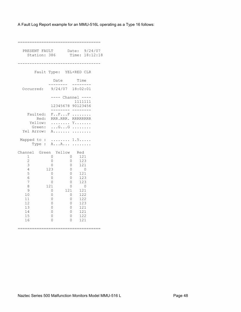
Naztec Series 500 Malfunction Monitors Model MMU-516 L Page 48
A Fault Log Report example for an MMU-516L operating as a Type 16 follows: =================================== PRESENT FAULT Date: 9/24/07 Station: 386 Time: 18:12:18 ----------------------------------- Fault Type: YEL+RED CLR Date Time -------- -------- Occurred: 9/24/07 18:02:01 ---- Channel ---- 1111111 12345678 90123456 -------- -------- Faulted: F..F...F ........ Red: RRR.RRR. RRRRRRRR Yellow: ........ Y....... Green: ...G...G ........ Yel Arrow: A....... ........ Mapped to : ........ 1.5..... Type : A...A... ........ Channel Green Yellow Red 1 0 0 121 2 0 0 123 3 0 0 121 4 123 0 0 5 0 0 121 6 0 0 123 7 0 0 123 8 121 0 0 9 0 121 121 10 0 0 122 11 0 0 122 12 0 0 123 13 0 0 121 14 0 0 121 15 0 0 122 16 0 0 121 ===================================

Naztec Series 500 Malfunction Monitors Model MMU-516 L Page 49
=================================== FAULT REPORT Date: 9/24/07 Station: 386 Time: 18:12:20 Avenue D. @ First St. ----------------------------------- Fault # 1 Type: INDICATION Date Time -------- -------- Occurred: 9/24/07 16:00:42 Ended: 9/24/07 17:01:15 ---- Channel ---- 1111111 12345678 90123456 -------- -------- Faulted: ....F... ........ Red: ..RR.RRR RRRRRRRR Yellow: ........ Y.Y..... Green: .G..G... ........ Yel Arrow: A...A... ........ Mapped to : ........ 1.5..... Type : A...A... ........ Fault # 2 Type: INDICATION Date Time -------- -------- Occurred: 9/24/07 14:56:23 Ended: 9/24/07 15:58:29 ---- Channel ---- 1111111 12345678 90123456 -------- -------- Faulted: ......F. ........ Red: RR.RRR.R RRRRRRRR Yellow: ......Y. ........ Green: ..G...G. ........ Yel Arrow: ........ ........ Mapped to : ........ 1.5..... Type : A...A... ........ ========= End of Report ========= In the previous example, the report was requested after the fault had been cleared (“There is no Present Fault”). If the MMU was in a faulted state when the Fault Log Report was requested, the Present Fault Report would precede the Fault Log Report.

Naztec Series 500 Malfunction Monitors Model MMU-516 L Page 50
8.4.4 Trace Log Report The MMU-516L records a trace record of each monitor input change following a fault condition. Each trace event record is time stamped in tenths of a second following the occurrence of the fault and recorded in the Trace Log. These trace event records are numbered sequentially starting with the most recent event. A Trace Log Report example for an MMU-516L operating as a Type 16 follows: =================================== TRACE REPORT Date: 7/ 5/05 Station: 0 Time: 15:37:05 ----------------------------------- Trace # 1 ---- Channel ---- 1111111 7/ 5/05 12345678 90123456 14:46:04.61 -------- -------- Red: ........ ........ Yellow: ........ ........ Green: ........ ........ Input Status Input Status ----------- ------ ------- ------ Red Enable: ON 24V #1: OK CVM: ON 24V #2: OK 24V Mon Inh: OFF AC Line: OK Local Flash: OFF Type: 16 Port 1 Dis: OFF ----------------------------------- Trace # 2 ---- Channel ---- 1111111 7/ 5/05 12345678 90123456 14:46:04.11 -------- -------- Red: R.RR.RRR RRRRRRRR Yellow: ....Y... ........ Green: .G...... ........ Input Status Input Status ----------- ------ ------- ------ Red Enable: ON 24V #1: OK CVM: ON 24V #2: OK 24V Mon Inh: OFF AC Line: OK Local Flash: OFF Type: 16 Port 1 Dis: OFF -----------------------------------

Naztec Series 500 Malfunction Monitors Model MMU-516 L Page 51
8.5 Miscellaneous Reports & Commands The MMU-516L provides several miscellaneous reports accessed by a keyboard command as described in this section. These reports include the Present Fault Report, AC Line Voltmeter Function, Clear Power Log Function, and Clear Fault Log Function.
8.5.1 Present Fault Report The Present Fault Report output is identical to the formal of the Fault Log, except only the present fault is displayed instead of a listing of the last 20 faults. This report is accessed from the MMU keyboard by pressing PR[ENTER].
8.5.2 AC Line Voltmeter Function A real-time status display of the AC line voltage may be accessed using the command VM[ENTER]. This following status display indicates the current AC line voltage:
AC Line Voltage 115
8.5.3 Clear Power Log Function The Power Log may be cleared of all stored power events and uninitialized data by the command CP[ENTER]. This following display is issued after the log is cleared.
Power Log Cleared
8.5.4 Clear Fault Log Function The Fault Log may be cleared and initialized using the command CF[ENTER]. The following display is issued after the Fault Log is created:
Fault Log Cleared

Naztec Series 500 Malfunction Monitors Model MMU-516 L Page 52
9. APPENDIX A - CONNECTOR PINOUTS
9.1 Type 16 Connector A
Pin Signal Pin Signal A AC Line f Channel 6 Yellow B Output Relay 1 Open g Channel 5 Yellow (closes when fault occurs) h Channel 3 Yellow C Output Relay 2 Closed i Channel 15 Green (opens when fault occurs) j Channel 2 Yellow D Channel 12 Green k Channel 1 Yellow E Channel 11 Green m Controller Voltage Monitor F Channel 10 Green n +24 V Monitor Inhibit G Channel 9 Green p Output Relay 1 Closed H Channel 8 Green (opens when fault occurs) J Channel 7 Green q Output Relay 2 Open K Channel 6 Green (closes when fault occurs) L Channel 5 Green r Channel 12 Walk (Type 12 only) M Channel 4 Green s Channel 11 Walk (Type 12 only) N Channel 3 Green t Channel 9 Walk (Type 12 only) P Channel 2 Green u Channel 16 Yellow R Channel 1 Green v Channel 15 Yellow S +24 V Monitor I w Channel 13 Yellow T Logic Ground x Channel 4 Yellow U Earth Ground y Channel 14 Green V AC Neutral z Channel 13 Green W Output Relay 1 Common X Output Relay 2 Common AA Spare 1 Y Channel 12 Yellow BB Reset Z Channel 11 Yellow CC Cabinet Interlock A DD Cabinet Interlock B a Channel 10 Walk (Type 12 only) EE Channel 14 Yellow b Channel 10 Yellow FF Channel 16 Green c Channel 9 Yellow GG Spare 2 d Channel 8 Yellow HH Type Select e Channel 7 Yellow
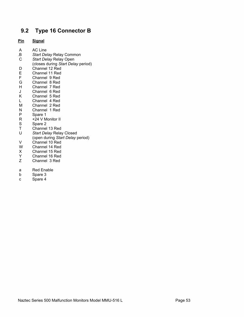
Naztec Series 500 Malfunction Monitors Model MMU-516 L Page 53
9.2 Type 16 Connector B
Pin Signal A AC Line .B Start Delay Relay Common C Start Delay Relay Open (closes during Start Delay period) D Channel 12 Red E Channel 11 Red F Channel 9 Red G Channel 8 Red H Channel 7 Red J Channel 6 Red K Channel 5 Red L Channel 4 Red M Channel 2 Red N Channel 1 Red P Spare 1 R +24 V Monitor II S Spare 2 T Channel 13 Red U Start Delay Relay Closed (open during Start Delay period) V Channel 10 Red W Channel 14 Red X Channel 15 Red Y Channel 16 Red Z Channel 3 Red a Red Enable b Spare 3 c Spare 4
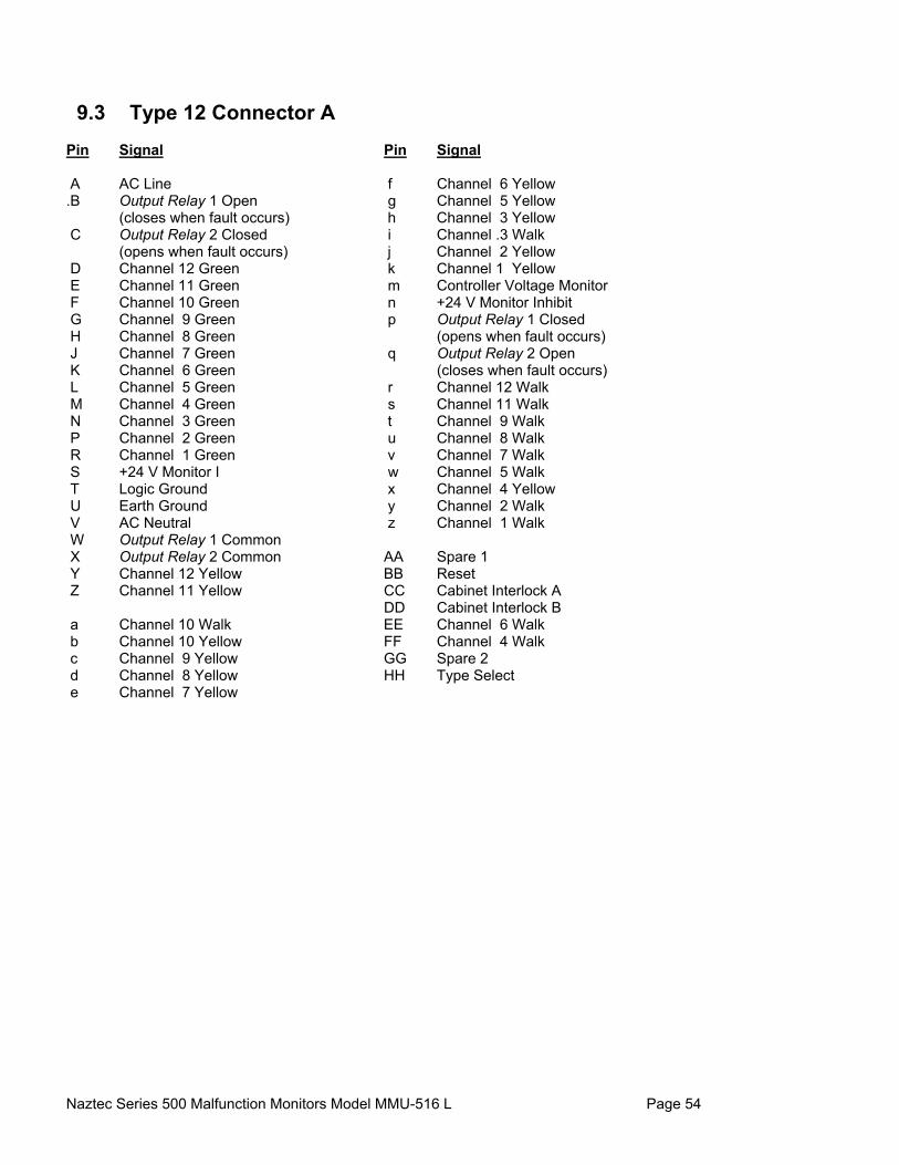
Naztec Series 500 Malfunction Monitors Model MMU-516 L Page 54
9.3 Type 12 Connector A
Pin Signal Pin Signal A AC Line f Channel 6 Yellow .B Output Relay 1 Open g Channel 5 Yellow (closes when fault occurs) h Channel 3 Yellow C Output Relay 2 Closed i Channel .3 Walk (opens when fault occurs) j Channel 2 Yellow D Channel 12 Green k Channel 1 Yellow E Channel 11 Green m Controller Voltage Monitor F Channel 10 Green n +24 V Monitor Inhibit G Channel 9 Green p Output Relay 1 Closed H Channel 8 Green (opens when fault occurs) J Channel 7 Green q Output Relay 2 Open K Channel 6 Green (closes when fault occurs) L Channel 5 Green r Channel 12 Walk M Channel 4 Green s Channel 11 Walk N Channel 3 Green t Channel 9 Walk P Channel 2 Green u Channel 8 Walk R Channel 1 Green v Channel 7 Walk S +24 V Monitor I w Channel 5 Walk T Logic Ground x Channel 4 Yellow U Earth Ground y Channel 2 Walk V AC Neutral z Channel 1 Walk W Output Relay 1 Common X Output Relay 2 Common AA Spare 1 Y Channel 12 Yellow BB Reset Z Channel 11 Yellow CC Cabinet Interlock A DD Cabinet Interlock B a Channel 10 Walk EE Channel 6 Walk b Channel 10 Yellow FF Channel 4 Walk c Channel 9 Yellow GG Spare 2 d Channel 8 Yellow HH Type Select e Channel 7 Yellow

Naztec Series 500 Malfunction Monitors Model MMU-516 L Page 55
9.4 Type 12 Connector B
Pin Signal A AC Line .B Start Delay Relay Common C Start Delay Relay Open (closes during Start Delay period) D Channel 12 Red E Channel 11 Red F Channel 9 Red G Channel 8 Red H Channel 7 Red J Channel 6 Red K Channel 5 Red L Channel 4 Red M Channel 2 Red N Channel 1 Red P Spare 1 R +24 V Monitor II S Spare 2 T Channel 13 Red (Type 16 only) U Start Delay Relay Closed (open during Start Delay period) V Channel 10 Red W Channel 14 Red (Type 16 only) X Channel 15 Red (Type 16 only) Y Channel 16 Red (Type 16 only) Z Channel 3 Red a Red Enable b Spare 3 c Spare 4
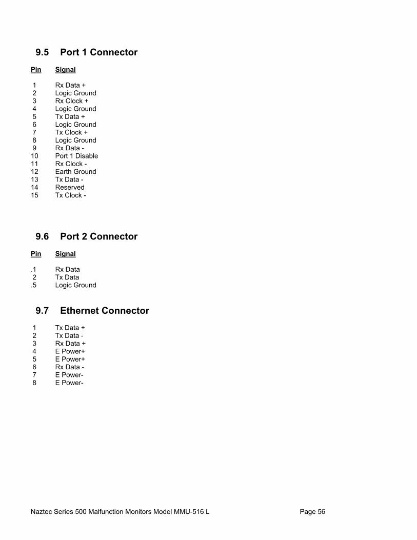
Naztec Series 500 Malfunction Monitors Model MMU-516 L Page 56
9.5 Port 1 Connector
Pin Signal 1 Rx Data + 2 Logic Ground 3 Rx Clock + 4 Logic Ground 5 Tx Data + 6 Logic Ground 7 Tx Clock + 8 Logic Ground 9 Rx Data - 10 Port 1 Disable 11 Rx Clock - 12 Earth Ground 13 Tx Data - 14 Reserved 15 Tx Clock - 9.6 Port 2 Connector
Pin Signal .1 Rx Data 2 Tx Data .5 Logic Ground 9.7 Ethernet Connector
1 Tx Data + 2 Tx Data - 3 Rx Data + 4 E Power+ 5 E Power+ 6 Rx Data - 7 E Power- 8 E Power-
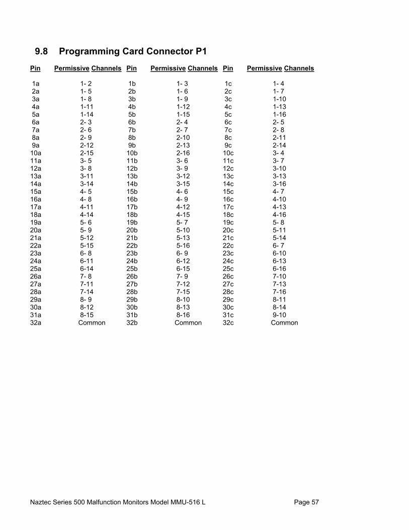
Naztec Series 500 Malfunction Monitors Model MMU-516 L Page 57
9.8 Programming Card Connector P1
Pin Permissive Channels Pin Permissive Channels Pin Permissive Channels 1a 1- 2 1b 1- 3 1c 1- 4 2a 1- 5 2b 1- 6 2c 1- 7 3a 1- 8 3b 1- 9 3c 1-10 4a 1-11 4b 1-12 4c 1-13 5a 1-14 5b 1-15 5c 1-16 6a 2- 3 6b 2- 4 6c 2- 5 7a 2- 6 7b 2- 7 7c 2- 8 8a 2- 9 8b 2-10 8c 2-11 9a 2-12 9b 2-13 9c 2-14 10a 2-15 10b 2-16 10c 3- 4 11a 3- 5 11b 3- 6 11c 3- 7 12a 3- 8 12b 3- 9 12c 3-10 13a 3-11 13b 3-12 13c 3-13 14a 3-14 14b 3-15 14c 3-16 15a 4- 5 15b 4- 6 15c 4- 7 16a 4- 8 16b 4- 9 16c 4-10 17a 4-11 17b 4-12 17c 4-13 18a 4-14 18b 4-15 18c 4-16 19a 5- 6 19b 5- 7 19c 5- 8 20a 5- 9 20b 5-10 20c 5-11 21a 5-12 21b 5-13 21c 5-14 22a 5-15 22b 5-16 22c 6- 7 23a 6- 8 23b 6- 9 23c 6-10 24a 6-11 24b 6-12 24c 6-13 25a 6-14 25b 6-15 25c 6-16 26a 7- 8 26b 7- 9 26c 7-10 27a 7-11 27b 7-12 27c 7-13 28a 7-14 28b 7-15 28c 7-16 29a 8- 9 29b 8-10 29c 8-11 30a 8-12 30b 8-13 30c 8-14 31a 8-15 31b 8-16 31c 9-10 32a Common 32b Common 32c Common

Naztec Series 500 Malfunction Monitors Model MMU-516 L Page 58
9.9 Programming Card Connector P2
Pin Permissive Channels Pin Permissive Channels Pin Permissive Channels 1a 9-11 1b 9-12 1c 9-13 2a 9-14 2b 9-15 2c 9-16 3a 10-11 3b 10-12 3c 10-13 4a 10-14 4b 10-15 4c 10-16 5a 11-12 5b 11-13 5c 11-14 6a 11-15 6b 11-16 6c 12-13 7a 12-14 7b 12-15 7c 12-16 8a 13-14 8b 13-15 8c 13-16 9a 14-15 9b 14-16 9c 15-16 Function Function Function 10a MYCD - 1 10b MYCD - 2 10c MYCD - 3 11a MYCD - 4 11b MYCD - 5 11c MYCD - 6 12a MYCD - 7 12b MYCD - 8 12c MYCD - 9 13a MYCD -10 13b MYCD -11 13c MYCD -12 14a MYCD -13 14b MYCD -14 14c MYCD -15 15a MYCD -16 15b Reserved 15c Reserved 16a Reserved 16b Reserved 16c Reserved 17a Reserved 17b Reserved 17c Reserved 18a Reserved 18b Reserved 18c Reserved 19a Reserved 19b Reserved 19c Reserved 20a Reserved 20b Reserved 20c Reserved 21a Min Flash b8 21b Min Flash b4 21c Min Flash b2 22a Min Flash b1 22b 24V Latch Enable 22c CVM Latch Enable 23a Reserved 23b Reserved 23c Reserved 24a Reserved 24b Reserved 24c Reserved 25a Reserved 25b Reserved 25c Reserved 26a Reserved 26b Reserved 26c Reserved 27a Reserved 27b Reserved 27c Reserved 28a Reserved 28b Reserved 28c Reserved 29a Reserved 29b Reserved 29c Reserved 30a Reserved 30b Reserved 30c Reserved 31a Reserved 31b Reserved 31c Reserved 32a Common 32b Common 32c Common
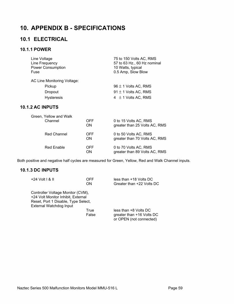
Naztec Series 500 Malfunction Monitors Model MMU-516 L Page 59
10. APPENDIX B - SPECIFICATIONS
10.1 ELECTRICAL
10.1.1 POWER
Line Voltage 75 to 150 Volts AC, RMS Line Frequency 57 to 63 Hz., 60 Hz nominal Power Consumption 10 Watts, typical Fuse 0.5 Amp, Slow Blow AC Line Monitoring Voltage: Pickup 96 ± 1 Volts AC, RMS Dropout 91 ± 1 Volts AC, RMS Hysteresis 4 ± 1 Volts AC, RMS
10.1.2 AC INPUTS Green, Yellow and Walk Channel OFF 0 to 15 Volts AC, RMS ON greater than 25 Volts AC, RMS Red Channel OFF 0 to 50 Volts AC, RMS ON greater than 70 Volts AC, RMS Red Enable OFF 0 to 70 Volts AC, RMS ON greater than 89 Volts AC, RMS Both positive and negative half cycles are measured for Green, Yellow, Red and Walk Channel inputs.
10.1.3 DC INPUTS +24 Volt I & II OFF less than +18 Volts DC ON Greater than +22 Volts DC Controller Voltage Monitor (CVM), +24 Volt Monitor Inhibit, External
Reset, Port 1 Disable, Type Select, External Watchdog Input True less than +8 Volts DC False greater than +16 Volts DC or OPEN (not connected)
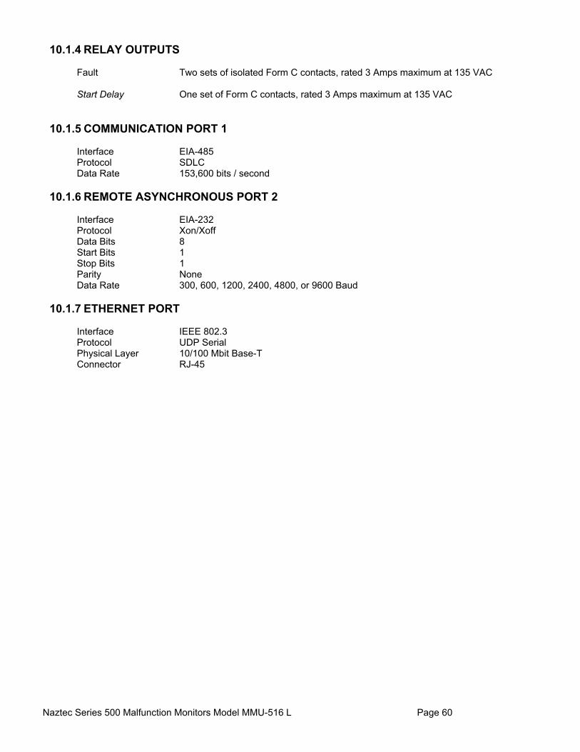
Naztec Series 500 Malfunction Monitors Model MMU-516 L Page 60
10.1.4 RELAY OUTPUTS Fault Two sets of isolated Form C contacts, rated 3 Amps maximum at 135 VAC Start Delay One set of Form C contacts, rated 3 Amps maximum at 135 VAC
10.1.5 COMMUNICATION PORT 1 Interface EIA-485 Protocol SDLC Data Rate 153,600 bits / second
10.1.6 REMOTE ASYNCHRONOUS PORT 2 Interface EIA-232 Protocol Xon/Xoff Data Bits 8 Start Bits 1 Stop Bits 1 Parity None Data Rate 300, 600, 1200, 2400, 4800, or 9600 Baud
10.1.7 ETHERNET PORT Interface IEEE 802.3 Protocol UDP Serial Physical Layer 10/100 Mbit Base-T Connector RJ-45

Naztec Series 500 Malfunction Monitors Model MMU-516 L Page 61
10.2 TIMING FUNCTIONS
Conflict No Fault less than 200 milliSeconds Fault greater than 450 milliSeconds Red Failure No Fault less than 700 milliSeconds Fault greater than 1000 milliSeconds +24 Volt I & II No Fault less than 125 milliSeconds Fault greater than 175 milliSeconds Controller Voltage Monitor (CVM) No Fault less than 125 milliSeconds Fault greater than 175 milliSeconds Yellow Clearance No Fault greater than 2.8 Seconds Fault less than 2.6 Seconds Yellow + Red Clearance on conflicting Channels No Fault greater than 2.8 Seconds Fault less than 2.6 Seconds Dual Channel Indication No Fault less than 700 milliSeconds Fault greater than 1000 milliSeconds MMU Power Interruption No response less than 450 milliSeconds Respond greater than 500 milliSeconds Port 1 Failure Nominal 300 milliSeconds Field Check Failure Nominal 800 milliSeconds Start Delay 2.0 ± 0.5 Seconds Minimum Flash Programmable from 6.0 ± 0.5 Seconds to 16 ± 0.5 Seconds (in 1 Second increments)
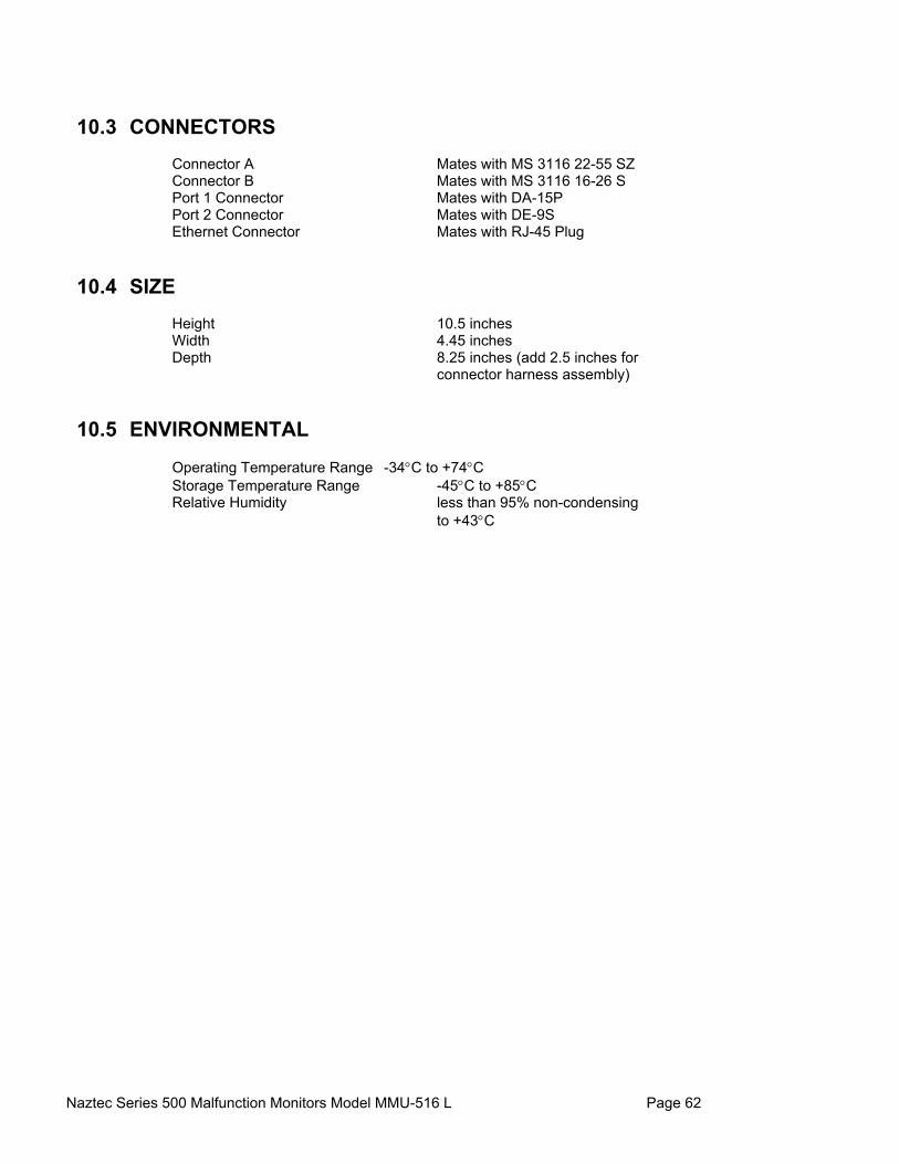
Naztec Series 500 Malfunction Monitors Model MMU-516 L Page 62
10.3 CONNECTORS
Connector A Mates with MS 3116 22-55 SZ Connector B Mates with MS 3116 16-26 S Port 1 Connector Mates with DA-15P Port 2 Connector Mates with DE-9S Ethernet Connector Mates with RJ-45 Plug 10.4 SIZE
Height 10.5 inches Width 4.45 inches Depth 8.25 inches (add 2.5 inches for connector harness assembly) 10.5 ENVIRONMENTAL
Operating Temperature Range -34°C to +74°C Storage Temperature Range -45°C to +85°C Relative Humidity less than 95% non-condensing to +43°C
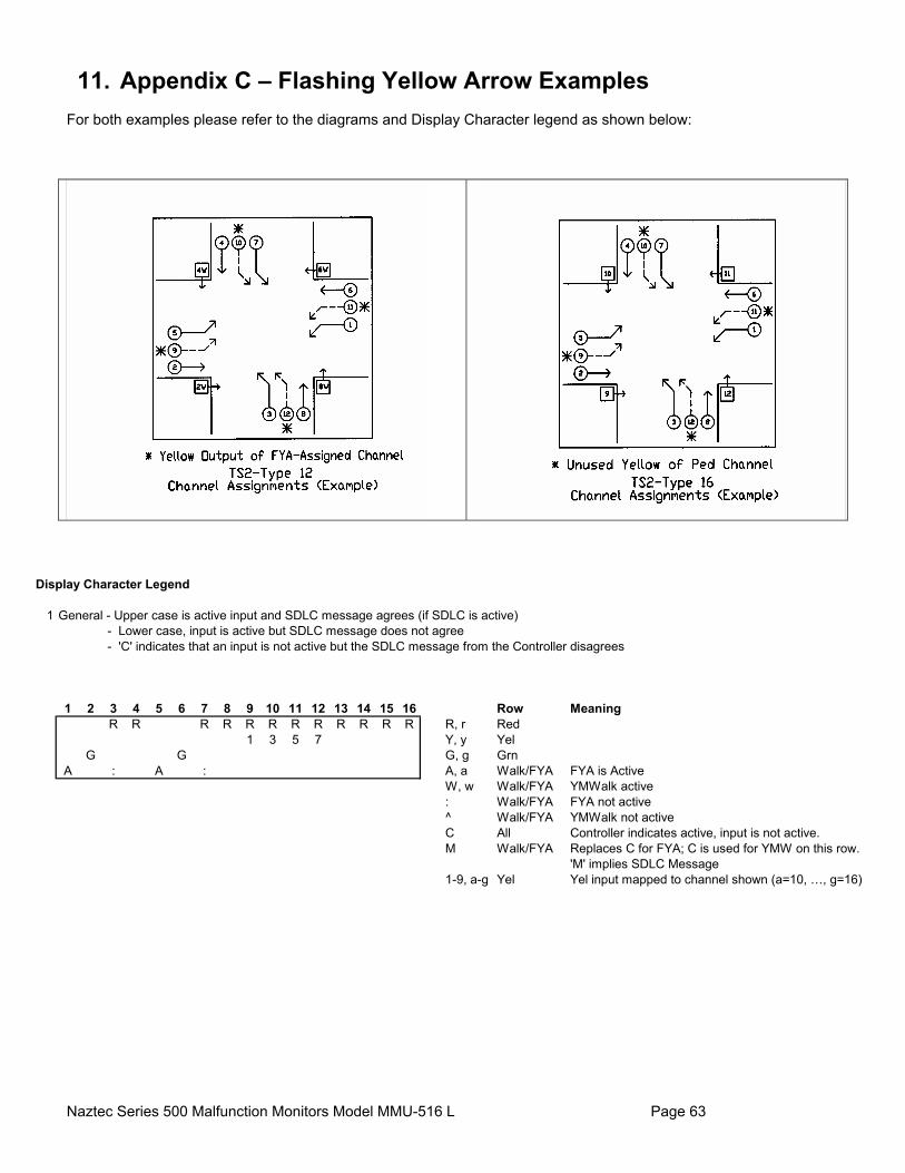
Naztec Series 500 Malfunction Monitors Model MMU-516 L Page 63
11. Appendix C – Flashing Yellow Arrow Examples For both examples please refer to the diagrams and Display Character legend as shown below:
Display Character Legend
1 General - Upper case is active input and SDLC message agrees (if SDLC is active) - Lower case, input is active but SDLC message does not agree - 'C' indicates that an input is not active but the SDLC message from the Controller disagrees
1 2 3 4 5 6 7 8 9 10 11 12 13 14 15 16 Row MeaningR R R R R R R R R R R R R, r Red
1 3 5 7 Y, y YelG G G, g Grn
A : A : A, a Walk/FYA FYA is ActiveW, w Walk/FYA YMWalk active: Walk/FYA FYA not active^ Walk/FYA YMWalk not activeC All Controller indicates active, input is not active.M Walk/FYA Replaces C for FYA; C is used for YMW on this row.
'M' implies SDLC Message1-9, a-g Yel Yel input mapped to channel shown (a=10, …, g=16)

Naztec Series 500 Malfunction Monitors Model MMU-516 L Page 64
11.1 Channels 9-12 Pedestrian Movement Assignment Example
Please refer to the Diagram labeled TS2 Type 12 Channel assignments at the beginning of this Appendix
FYA Programming 4 Left Turns, Peds on 9 - 128/30/2007
CONTROLLER
Channel 1 2 3 4 5 6 7 8 9 10 11 12 13 14 15 16Type OLP VEH OLP VEH OLP VEH OLP VEH PED PED PED PED OLP OLP OLP OLP
# 2 2 4 4 6 6 8 8 2 4 6 8 9 9 9 9
NotesOverlap 2 4 6 8 1
Olp Included 1 3 5 7Olp Modifier 2 4 6 8FYA out on Chan 9 10 11 12OLP Type R-T/OTH R-T/OTH R-T/OTH R-T/OTHOLP Type+ FLYel-4 FLYel-4 FLYel-4 FLYel-4
MMU-516L
FYA # 1 2 3 4Type FYA FYA FYA FYAFYA Channel 1 3 5 7Yel Input Chan 9 10 11 12Permissive 1 2 4 6 8Permissive 2 9 10 11 12
Please note that the Channel numbers in parentheses are not programmed on the Program Card.Their FYA functionality is entered on the FYA Setup Screen as indicated above.
MMU Prog CardChannel 1 2 3 4 5 6 7 8 9 10 11 12 13 14 15 16
1 (2) 5 6 (9) 112 5 6 9 113 (4) 7 8 (10) 124 7 8 10 125 (6) 9 (11)6 9 117 (8) 10 (12)8 10 129 11
10 121112131415
as an alternate way output the FYA signal.
Controller FYA Overlap Setup
MMU FYA Setup
Controller Channel Assignments
Assign only Even-numbered overlaps as FYA.Odd-numbered overlaps one less than FYAmust remain unassigned b/c the yellow is used

Naztec Series 500 Malfunction Monitors Model MMU-516 L Page 65
11.2 Channels 13-16 Pedestrian Movements Assignment Example
Please refer to the Diagram labeled TS2 Type 16 Channel assignments at the beginning of this Appendix.
FYA Programming 4 Left Turns, Peds on 13-168/30/2007
CONTROLLER
Channel 1 2 3 4 5 6 7 8 9 10 11 12 13 14 15 16Type OLP VEH OLP VEH OLP VEH OLP VEH OLP OLP OLP OLP PED PED PED PED
# 2 2 4 4 6 6 8 8 9 9 9 9 2 4 6 8
NotesOverlap 2 4 6 8 1
Olp Included 1 3 5 7Olp Modifier 2 4 6 8FYA out on Chan 13 14 15 16OLP Type R-T/OTH R-T/OTH R-T/OTH R-T/OTHOLP Type+ FLYel-4 FLYel-4 FLYel-4 FLYel-4
MMU-516L
FYA # 1 2 3 4Type FYA FYA FYA FYAFYA Channel 1 3 5 7Yel Input Chan 13 14 15 16Permissive 1 2 4 6 8Permissive 2 13 14 15 16
Please note that the Channel numbers in parentheses are not programmed on the Program Card.Their FYA functionality is entered on the FYA Setup Screen as indicated above.
MMU Prog CardChannel 1 2 3 4 5 6 7 8 9 10 11 12 13 14 15 16
1 (2) 5 6 (13) 152 5 6 13 153 (4) 7 8 (14) 164 7 8 14 165 (6) 13 (15)6 13 157 (8) 14 (16)8 14 169
10111213 1514 1615
Controller Channel Assignments
Controller FYA Overlap Setup
MMU FYA Setup
Assign only Even-numbered overlaps as FYA.Odd-numbered overlaps one less than FYAmust remain unassigned b/c the yellow is usedas an alternate way to get the FYA output.