for mechanical & electrical systems at 7 newton’s …
TRANSCRIPT

SPECIFICATION
FOR
MECHANICAL & ELECTRICAL SYSTEMS
AT
7 NEWTON’S COURT
1934 - ISSUE 1 AUGUST 2021

1934 – 7 Newton’s Court August 2021
SPECIFICATION FOR MECHANICAL & ELECTRICAL SYSTEMS AT 7 NEWTON’S COURT, DARTFORD DA2 6QL
CONTENTS
SECTION 1 MAIN CONTRACT CONDITIONS NOT USED (REFER TO MAIN CONTRACT)
SECTION 2 MECHANICAL & ELECTRICAL SYSTEMS ENGINEERING PREAMBLES
SECTION 3 MATERIALS AND WORKMANSHIP REQUIREMENTS MECHANICAL SYSTEMS
SECTION 4 MATERIALS AND WORKMANSHIP REQUIREMENTS ELECTRICAL SYSTEMS
SECTION 5 MECHANICAL SYSTEMS SPECIFICATION
SECTION 6 ELECTRICAL SYSTEMS SPECIFICATION
SECTION 7 MECHANICAL SCHEDULES
SECTION 8 ELECTRICAL SCHEDULES
SECTION 9 SCHEDULE OF DRAWINGS
SECTION 10 PRICING SCHEDULES

1934 – 7 Newton’s Court August 2021
SPECIFICATION FOR MECHANICAL & ELECTRICAL SYSTEMS AT 7 NEWTON’S COURT, DARTFORD DA2 6QL
DOCUMENT ISSUE STATUS
Issue
Description Date Author Checked by
01 Tender Issue 06th August 2021 CC/GH JS/PB

QA – BSP 34-08/15
1934 – 7 Newton’s Court Section 2/Page 1 August 2021
ENGINEERING PREAMBLES

QA – BSP 34-08/15
1934 – 7 Newton’s Court Section 2/Page 2 August 2021
SECTION 2 ENGINEERING PREAMBLES CONTENTS 1.0 SCOPE OF WORK
2.0 STATUTORY REQUIREMENTS
3.0 DRAWINGS AND SPECIFICATION
4.0 INSTALLER’S DESIGN RESPONSIBILITY
5.0 ALTERNATIVE EQUIPMENT SUPPLIERS
6.0 WARRANTY TO BE GIVEN BY THE SUB-CONTRACTOR EMPLOYED BY THE
CONTRACTOR
7.0 TENDER RETURNS
8.0 SCHEDULE OF RATES AND QUANTITIES
9.0 POST TENDER MEETING
10.0 TECHNICAL METHOD STATEMENTS
11.0 QUALITY ASSURANCE PROCEDURES
12.0 C.D.M./HEALTH & SAFETY PLAN
13.0 SITE DOCUMENTATION
14.0 SCHEDULE OF INSTALLER’ CAD DRAWINGS
15.0 CAD DRAWINGS BY THE INSTALLER
16.0 PRODUCTION OF INSTALLATION/WORKING CAD DRAWINGS/BUILDERS WORK
DRAWINGS.
17.0 CAD INSTALLATION/WORKING DRAWINGS
18.0 CAD BUILDER’S WORK DRAWINGS
19.0 COMMENTS ON INSTALLER’S CAD DRAWINGS.
20.0 CAD RECORD DRAWINGS
21.0 OPERATING AND MAINTENANCE INSTRUCTION MANUALS
22.0 PRODUCTION OF CAD RECORD DRAWINGS AND OPERATION AND
MAINTENANCE MANUALS FOR THE HEALTH & SAFETY FILE.
23.0 SETTING OUT OF WORKS
24.0 ACCESS FOR PLANT INSTALLATION AND SUBSEQUENT REMOVAL
25.0 ORDERS FOR MATERIAL/EQUIPMENT/SPECIALIST SYSTEMS.

QA – BSP 34-08/15
1934 – 7 Newton’s Court Section 2/Page 3 August 2021
26.0 SUITABILITY OF MATERIALS
27.0 SAMPLES
28.0 PROGRAMME AND ORDERING REPORTING.
29.0 SECONDARY STEELWORK/EASE OF MAINTENANCE/MACHINE GUARDS
30.0 EQUIPMENT AND PLANT PERFORMANCE GUARANTEES
31.0 PROTECTION OF EQUIPMENT
32.0 SITE CLEANLINESS
33.0 MATERIALS AND WORKMANSHIP
34.0 INSPECTION BEFORE CONCEALMENT
35.0 COMMISSIONING AND TESTING.
36.0 FUEL POWER AND CONSUMABLES FOR THE ENGINEERING WORKS
37.0 INSTRUCTIONS OF EMPLOYERS’S REPRESENTATIVE
38.0 CLIENT SPARES
39.0 PLANT LABELLING
40.0 PRACTICAL COMPLETION
41.0 MAINTENANCE CONTRACT
42.0 MAINTENANCE KIT

QA – BSP 34-08/15
1934 – 7 Newton’s Court Section 2/Page 4 August 2021
SECTION 2 ENGINEERING PRE-AMBLES 1.0 SCOPE OF WORK 1.1 Throughout this document and the associated tender drawings, the term “Installer” shall refer
to the Installer appointed to undertake Mechanical, Electrical, or other engineering installation in any single or combined sub-contract as defined by the main contract documentation.
1.2 The term “Engineering System Installation” shall refer to each and every Installer from the
following schedule: .1 Mechanical .2 Electrical 1.3 All definitions shall be as described within the Main Contract preliminaries. The Installer shall
make a full reference to all the tender documentation to ensure that its offer fully complies with all responsibilities.
1.4 Where conflict occurs within or between any element clause or section of the contract tender
documentation, including drawings, it shall be the tenderer’s responsibility to give notice prior to return of the tender. In the absence of prior notice being given in advance of tender submission, the Architect shall remain the final Arbiter to ensure that a positive decision can be made as to which clause or item is selected.
1.5 The Installer shall be responsible for all works detailed in the Specification and shown on the
Tender Drawings, and in particular the following items, including all CAD facilities. 1.5.1 Undertaking specific detailed design as indicated herein.
1.5.2 Provision of co-ordinated CAD installation / working drawing for all services and detailed wiring diagrams for all equipment and control panels. All to be provided to the Employer on Autocad, release 2000 or later format.
1.5.3 Inspecting all plant, equipment and materials as delivered or where specified at the manufacturer’s works.
1.5.4 Fixing or installing correctly all plant, equipment and materials.
1.5.5 Ensuring all associated work such as electrical wiring, connecting pipework, builders work etc., is properly executed.
1.5.6 Testing and commissioning the complete installation including making adjustments and balancing as necessary.

QA – BSP 34-08/15
1934 – 7 Newton’s Court Section 2/Page 5 August 2021
1.5.7 Demonstrating that the equipment is capable of the performance and method of operation specified to the satisfaction and acceptance of the Architect.
1.5.8 Demonstrating that the overall and complete systems perform correctly in the required manner and as intended by the Specification to the satisfaction and acceptance of the Architect.
1.5.9 Providing all installation/working, builder’s work and record drawings on CAD. Showing the complete installation and structure, architectural form and other services systems. All drawings must be provided on Autocad 2000. The CAD systems being used by the Design Team are:
1.5.9.1 Architect and Brinson Staniland Partnership – Autocad 2000
1.5.10 At least 2 weeks prior to practical completion provide in final form, operating instructions and maintenance manuals for the complete systems as a word processed document and computer disk file. (Tender scheme to price for Microsoft Word, latest release). Manufacturers information shall be submitted as colour original hardcopy.
1.5.11 Providing the full set of test results in an approved format for all tests, commissioning and balancing operations as a word processed document and computer disk file. (Tender scheme to price for Microsoft Word)
1.5.12 At least one week before practical completion instruct the Employer’s staff in the use and operation and maintenance of the installations.
1.5.13 Handing over all specified tools, keys, spares, oils, chemicals etc.
2.0 STATUTORY REQUIREMENTS 2.1 The works shall comply with all current and relevant Statutory Instruments and Regulations
including, but not limited to the following:-
2.1.1 Regulations under the Electricity Supply Regulations 1937.
2.1.2 The Gas Safety Regulations.
2.1.3 The Health and Safety at Work Act.
2.1.4 The Clean Air Acts.
2.1.5 The Building Regulations
2.1.6 Regulations under the Factories Act.
2.1.7 The Control of Pollution Act.
2.1.8 The Pressure Systems and Transportable Gas Container Regulations.
2.1.9 The Electricity at Work Regulations.

QA – BSP 34-08/15
1934 – 7 Newton’s Court Section 2/Page 6 August 2021
2.1.10 Water Supply Regulations. 2.2 The works shall be carried out in accordance with the requirements and regulations of all
relevant local authorities, fire brigades, and water, gas and electricity authorities. 2.3 Any such portion of the works requiring the inspection and approval of such authorities shall
not be built-in, covered or otherwise obscured until such approval has been obtained. 2.4 Authorities shall be notified, as necessary, about the connection of electricity, gas, water and
drainage. 2.5 The Installer shall be responsible for liaison with the Main Contractor to facilitate the
programming and co-ordination of the various utilities to meet its installation programme. 2.6 Unless otherwise specified, the whole of the works shall comply with the requirements of all
relevant British Standards/BS Codes of Practice, European Standards, International Standards, CIBSE Recommendations and the Approved Documents of the Building Regulations.
3.0 DRAWINGS AND SPECIFICATION 3.1 The Installer shall carefully and thoroughly examine the drawings and the Specification, and fully
acquaint itself with the work to be done. The work shall comprise the whole of the labour and, unless otherwise indicated, materials to form a complete and effective working installation.
3.1.1 The Tenderer must, as part of its tender, return and identify any equipment that it intends to
select that causes any change to spatial requirements or allowances made in the tender scheme. 3.2 The tender drawings are prepared primarily to describe, in a basic manner, the design of
the mechanical and electrical works, the working principles of the systems and the general intended methods of installation. They are intended to be read in conjunction with the Specification to facilitate the preparation of the Installer’s estimate and tender and to enable all other participants to appreciate the interrelation of the mechanical and electrical works and the main works as a whole.
3.3 The tender drawings are accordingly part diagrammatic with runs of piping, ducts, cable
highways and the like being shown to small scale and not necessarily indicating exact installation positions.
3.4 The Installer shall take its own dimensions for both the preparation of its Tender and for the execution of the work, and it alone shall be responsible for the accuracy of such dimensions and of drawings made there from. All dimensions, specially marked on the tender drawings, shall be rigorously adhered to.

QA – BSP 34-08/15
1934 – 7 Newton’s Court Section 2/Page 7 August 2021
4.0 INSTALLER’S DESIGN RESPONSIBILITY 4.1 The Installer shall be responsible for the detailed design activities listed below, in addition to
those activities normally undertaken through the custom and practice of the industry, all of which shall be subject to the comment of the Architect.
4.1.1 The Installer shall be responsible for ensuring that the detailed design that he undertakes is fully
co-ordinated and compatible with the remainder of the project design. 4.1.2 All costs shall be allowed by the Installer for the complete interface of his works and the
remainder of the project. Specifically all supports will be provided by the Installer up to and including the final attachment to primary structure.
4.2 Comments by the Architect shall not relieve the Installer of its responsibility for the suitability
and correctness of its obligations within the contract documentation. 4.3 The Installer’s design obligations shall include:
4.3.1 Fabrication drawings and the co-ordinated installation working drawings and record drawings.
4.3.2 Drain and vent point locations and pipework gradients in accordance with latest BSRIA documents Application Guide. Flushing and Cleaning of Water Systems.
4.3.3 Bracket and support detailed design and locations. (All types, loads and locations must be declared to the Architect prior to installation for comment (10 working days).
4.3.4 Details of electrical wiring diagrams of all equipment supplied by the Installer showing all interconnections between equipment to enable the necessary wiring to be undertaken.
4.3.5 Details of all equipment component design and selection necessary insofar as such items have been selected by the Installer for that item of equipment to meet the engineering specification and performance indicated.
4.3.6 Automatic controls detailed design insofar as it is required to meet with full physical and operational requirements of the Engineering Specification. Where interface (relays or other devices) or modifications to hardware or software) are required the design and incorporation shall be the Installer’s responsibility.
4.3.7 Dimensioning of, and final installation details of, the Automatic Control panels and Motor Control Centres to suit the detailed requirements of particular manufacturer’s of plant and equipment such that:-
- Cable entry is possible in the selected location.
- Doors are not fouled by other plant, equipment, services or structural elements. - Safe operating and maintenance clearances are provided in all access

QA – BSP 34-08/15
1934 – 7 Newton’s Court Section 2/Page 8 August 2021
positions where installed on site. - Starter circuits are compatible with the actual equipment motor rating installed.
4.3.8 Fire alarm, Security and other specialist systems, component and cabling requirements to meet with particular manufacturer’s and the engineering specification’s requirements.
4.3.9 Attenuator design and selection to satisfy the particular and performance requirements of the specification, including spatial allowances made within tender drawings.
4.3.10 Design of elements of the scheme provided by the Installer for self weight and other applied forces/loadings in reasonable use. In particular any buried tanks or pipe work that will require designed anchorage, encasement or foundations.
4.3.11 Thermal expansion accommodation and anchorage, including provision of bellows or bends.
4.3.12 Acoustic design or modification of equipment to meet with the noise levels specified. All levels to be achieved with all plant operating.
4.3.13 Valve, damper and access locations.
4.3.14 System water capacities, and chemical additives – and arranging of the facilities required by the latest BSRIA Application Guide Pre-Commission Cleaning Of Water Systems.
4.3.15 Selection of all anti-vibration mountings to suit the particular application of the mounts.
4.3.16 Final locations of control sensors detectors and thermostats.
4.3.17 Capacity, location and design of electrical conduit systems, similarly trunking where used in lieu of multi-conduit installation.
4.3.18 Duct platforms, access covers and gratings, ladders and additional structural steelwork where required and detailed in the sub-contract documentation.
4.3.19 Selection of regulation devices to comply with CIBSE Technical Memorandum TM8, Applications Manual AM1and BSRIA Application Guides; Commissioning of Water System and Commissioning of Air Systems.
4.3.20 Sizing of cable terminations on items of equipment provided under the Sub-Contract where cable sizes are specified.
4.3.21 Ensuring cable sizing selections as specified are not invalidated by Sub-Contractor selection of alternative routes during installation.
4.3.22 Detailed design of earthing and bonding requirements for electrical engineering services, mechanical engineering services, architectural and structural elements requiring earthing and bonding.
QA – BSP 34-08/15
1934 – 7 Newton’s Court Section 2/Page 9 August 2021
4.3.23 Fuse sizes installed in plug tops and fuse connections units are appropriate for the rating of connected equipment.
4.3.24 Sizing and detailed design of refrigerant pipework between items of equipment provided under contract works.
5.0 ALTERNATIVE EQUIPMENT SUPPLIERS 5.1 The Installer shall include in its tender for equipment supplied by the named manufacturer
stated in the Specification. 5.2 Should the Installer so wish, he may offer as an alternative, equipment from one of the named
alternative equipment suppliers in the specification. This offer should be included on the alternative equipment appendix, and the cost differential between it and the named manufacturer shall be indicated in the space provided.
5.3 Where the Installer chooses to offer an alternative manufacturer’s equipment the Installer shall
include for all measures necessary to make the equipment and the total installation equivalent to that specified e.g. upgrading pumps where pressure drops are higher, upgrading cable sizes where electrical loads are higher and all necessary draughting and co-ordination to demonstrate the successful installation.
5.4 Alternative suppliers not named in the Specification shall not be acceptable at tender stage. 5.5 Additional costs resulting from non-compliance with the above shall be borne by the Installer.

QA – BSP 34-08/15
1934 – 7 Newton’s Court Section 2/Page 10 August 2021
6.0 WARRANTY TO BE GIVEN BY THE SUB-CONTRACTOR EMPLOYED BY THE CONTRACTOR
6.1 The Installer shall provide the employer with the warranty as detailed herein. THIS AGREEMENT is made this …………………………….. day of 200 Between …………………………………………………………………………. Whose registered offices are situated at………………………………………. (herewithinafter called the “Employer” ) of the other part. WHEREAS 1. The Sub-Contractor has been invited to tender for the carrying out of (hereinafter
called the “Sub-Contract Works”) it being intended that the Sub-Contract Works shall form part of the works to be carried out at……………………………………….(hereinafter called “the Works) under an agreement dated (hereinafter called the Agreement) made between the Employer of the one part and the Main Contractor when appointed (hereinafter called the “Main Contractor”) of the other part.
2. The Employer has appointed ……………………….………………. to be the Architect
for the purpose of the Works, the Agreement and this Agreement. 3. It is intended that the Sub-Contractor shall also carry out certain design or design
development work in respect of the Sub-Contractor Works, for submission to the Architect and subsequent issue to the Main Contractor when appointed.
4. Nothing contained in this Deed is intended to render the Architect in any way liable to
the Sub-Contractor in relation to matters in this Deed. 5. In consideration of the Employer approving the tender of the Sub-Contractor the Sub-
Contractor agrees to give the Employer the warranties hereinafter appearing. NOW IT IS AGREED AS FOLLOWS:- The Sub-Contractor hereby warrants to the Employer that:-
(a) If and insofar as the design or the development and completion of the design for the Sub-Contract Works has been or will be undertaken by the Sub-Contractor and in so far as the selection or approval of materials and goods for the Sub-Contract Works has or will be carried out by it, the Sub-Contractor shall have, in respect of any defect, insufficiency, error or omission in such design or selection, the like liability to the Employer (whether under statute or at common law) as would any other appropriate professional designer holding himself out as competent to take on work of design or

QA – BSP 34-08/15
1934 – 7 Newton’s Court Section 2/Page 11 August 2021
selection who, acting independently under a separate contract with the Employer, has supplied such design, developed and completed such design , approved or selected such materials and goods for or in connection with such works as the Sub-Contract Works in such circumstances.
(b) The Sub-Contractor will, so far as it lies within its power, use all reasonable endeavours
so to perform the Sub-Contract Works including supplying the Architect and/or Main Contractor with such information (including drawings as either may reasonably require) that the Main Contractor shall not become entitled to and extension of time under the Main Contract by reason of the Sub-Contractors failure so to perform the Sub-Contract Works.
Signed By A Director for and on behalf…………………………………………………………………………. the Sub-Contractor in the …………………………………………………………………………. presence of:- Name………………………………………………………………………………………………. Address………………………………………………………………………………………………. ……………………………………………………………………………………………… Description or Occupation…………………………………………………………………………… 7.0 TENDER RETURNS 7.1 Tenders for the Subcontract Works shall be submitted on the Tender Forms accompanying this
Specification. 7.2 Tenders received after the time stated may be rejected. 7.3 Tenders qualified in any way may be rejected. 7.4 No payment will be made for Tenders. 7.5 The Employer does not bind itself to accept the lowest, or any Tender. 7.6 The tender shall be a lump sum fixed price tender for all necessary work to provide the
installation as outlined to meet the Employers required specification.

QA – BSP 34-08/15
1934 – 7 Newton’s Court Section 2/Page 12 August 2021
8.0 SCHEDULE OF RATES AND QUANTITIES 8.1 The Installer shall forward within three working days after it shall have received notice that its
Tender is being considered for acceptance, a full priced out and qualified schedule of rates and quantities with each item priced, and totalled, to agree with the sub-totals and final total of the Tender. These prices shall be the basis for the valuation of any variation of the sub-Contract Works.
8.2 The priced schedule of rates shall be deemed to include for all items, whether mentioned in the
Schedule or not, for this Sub-Contract. Detailed rates are also required for all specialist Sub-Trader’s work included in the Sub-Contract.
8.3 Ancillary items not shown separately in the schedule will be assumed to be included in the
general rates stated. 9.0 POST TENDER MEETING 9.1 Upon selection of the prospective installers, a meeting may be convened to obtain the final
agreement of the Installers on all matters raised in the tender. 9.2 Specifically all matters relating to the production of contract information and site liaison shall be
agreed. 9.3 The agreed minutes of this meeting or meetings shall, if required by the Architect, form part of
the contract document to demonstrate that the Installer has understood its responsibilities. 10.0 TECHNICAL METHOD STATEMENTS 10.1 In advance of any works being carried out on site, the Installer shall submit for comment by the
Architect a technical method statement. 10.2 Technical method statement shall be provided for the following aspects of the installation. 10.2.1 Operating and Maintenance Manuals.
10.2.2 Record Drawings.
10.2.3 Installation/Workings Drawings.
10.2.4 Thermal Insulation.
10.2.5 Commission and Testing
10.2.6 Ductwork Installation

QA – BSP 34-08/15
1934 – 7 Newton’s Court Section 2/Page 13 August 2021
10.2.7 Pipework Installation
10.2.8 Automatic Control Installation
10.2.9 Plant Room Installation
10.2.10 Ceiling Void Installation
10.2.11 Floor Void Installation
10.2.12 Quality Control and Samples Procedure
10.2.13 Installer Liaison Procedures.
10.2.14 T.Q. (Technical Query) procedures. 11.0 QUALITY ASSURANCE PROCEDURES 11.1 The Installer shall provide, for agreement by the Architect, fully documented Quality Assurance
Procedure (QAP) in accord with ISO 9000, prior to commencement of draughting, procurement or installation.
11.2 The Installer’s QAP must be provided in concert and agreement with the main contract
procedures. 11.3 The QAP must detail specific procedures related to the tendered project and not be
generalised. 11.4 The QAP shall be provided by the Installer at tender, it’s content subject only to the Architect
and Main Contractor’s comment. 12.0 C.D.M./HEALTH & SAFETY PLAN 12.1 The Installer shall be responsible for developing, in conjunction with the Principal Contractor, a
full Health & Safety Plan prior to commencing operations on site and in doing so shall consider the work and materials of its own specialists and suppliers who will be involved with the Works.
12.2 The Installer shall ensure that its Plan is drawn up in a clear, coherent and logical fashion and
shall provide a comprehensive, fully indexed document which clearly identifies the risk assessment and health and safety issues.
12.3 It is a requirement that the Health & Safety Plan is, when necessary, updated as the project
proceeds to reflect any changes carried out during the construction works. The Installer shall participate in this process as required.

QA – BSP 34-08/15
1934 – 7 Newton’s Court Section 2/Page 14 August 2021
12.4 The Installer shall demonstrate to the Architect that sufficient resources have been allocated to perform the necessary duties under the C.D.M. Regulations and shall identify competent personnel responsible for Health & Safety on the site.
13.0 SITE DOCUMENTATION 13.1 Notwithstanding the requirements of the main contract preliminaries, each Installer shall also
allow for, and provide in a maintained indexed library, the following:- 13.1.1 Relevant copies of all technical equipment schedules ‘as delivered to site’ 13.1.2 Relevant technical literature on each type of equipment or component used within the
installation. 13.1.3 Copies of all relevant information. (Technical queries, relevant instructions, current
installation/working drawings, current programme) 13.1.4 Copies of all signed daywork sheets. 13.2 All of the above is to be accessible at all times that the site is open, by the Architect or its
representative. 13.3 All of the above shall be kept up to date and in good order. It is not for the installers use and
must be maintained complete. 14.0 SCHEDULE OF INSTALLER’ CAD DRAWINGS 14.1 The Installer shall, within two weeks of appointment, prepare a drawing schedule of all its
proposed drawings required for comment. The schedule shall indicate the following:-
14.1.1 Drawing number and revision number. 14.1.2 Drawing title and system. 14.1.3 Scale. 14.1.4 Latest date required on site. 14.1.5 Date required for final comments. 14.1.6 Date for submission for comments. 14.1.7 Date on which comments were received. 14.1.8 Date of commencement of drawing production.

QA – BSP 34-08/15
1934 – 7 Newton’s Court Section 2/Page 15 August 2021
14.2 The Installer shall revise and update its drawing schedule as necessary on a monthly basis taking into account any revision which may take place.
15.0 CAD DRAWINGS BY THE INSTALLER 15.1 The Installer shall provide the following drawings:- 15.1.1 Installation/Working drawings. 15.1.2 Builders Work drawings. 15.1.3 Plant and Equipment drawings. 15.1.4 Record drawings. 15.1.5 Floor and Ceiling drawings. 15.2 Drawings shall be to the B.S. International ‘A’ series. 15.3 All symbols shall be generally in accordance with B.S. 1553 and shall be approved prior to
preparation of any drawings. 15.4 Every drawing shall bear the name of the Contract as shown on the cover of this Specification. 15.5 Drawings shall be cross referenced for ease of interpretation. 15.6 All drawings shall be produced and presented on a CAD format agreed at tender (tender to
allow for Autocad 2000 Series with files in DWG formats. 16.0 PRODUCTION OF INSTALLATION/WORKING CAD DRAWINGS/BUILDERS
WORK DRAWINGS. 16.1 The production of co-ordinated composite installation/working and co-ordinated composite
builder’s work drawings require all engineering systems sub-contracts to produce information in concert and to a master programme.
16.1.1 It shall be the responsibility of the Mechanical Installer to attend and chair drawing production
meetings and the individual responsibility of each of the Engineering System Installers to attend the same meetings.
16.1.2 The purpose of the meetings shall be to resolve the effective production of the CAD co-
ordinated multidisciplinary composite installation/working and builder’s work drawings.
16.1.3 No allowance will be made for abortive draughting by any of the sub-contract packages due to lack of knowledge of each specific disciplines requirements.

QA – BSP 34-08/15
1934 – 7 Newton’s Court Section 2/Page 16 August 2021
16.1.4 No draughting should proceed until each sub-contract has agreed an overall spatial relationship with the remaining sub-contracts and the architectural form and structure.
16.1.5 Any installation that proceeds either without a suitably produced and commented upon drawing or without detailed information of the other local sub-contract packages, structure or architectural form is entirely at the Installers risk, no abortive costs will be allowed to rectify any problems arising.
16.2 From the description of the required content of the installation drawings given elsewhere in this
document, it is to be noted that all relevant details of all elements of Structure, Architectural form and Engineering System included within the provision of the completed project, are to be indicated upon composite installation/working drawings. All drawings shall be produced and presented in printed form and on computer disk using a CAD system conforming with the Autocad series system mentioned in previous sections. All drawings shall have independent layers of information from the following minimum schedule.
· Structure and Architectural form. · Mechanical works. · Electrical works.
All shall be displayed ‘on screen’ in different colours.
16.3 Each of the Engineering System Installers shall produced independent working and builders work
drawings, as specified elsewhere. Each Installer shall be responsible for the accuracy of its own information and for the physical relationship of its own works to the remainder.
16.4 Notwithstanding the overall responsibility of the Main Contractor to programme and co-
ordinate the entire works, the Mechanical Installer shall have the following particular additional responsibilities.
16.5 Mechanical Installer’s Additional Responsibilities 16.5.1 The Mechanical Installer shall be responsible for the production of the co-ordinated composite
installation/working drawings as described within this document i.e it shall be the mechanical installer’s responsibility for the production of composite installation and working drawings upon each of which all co-ordinated details of the structure, architectural form, and mechanical, electrical are indicated.
16.5.2 As for the installation/working drawings, the mechanical installer shall produce composite
builders work drawings with its own and all other contract package requirements properly defined.
16.5.3 The Mechanical Installer shall arrange in the Main Contract a reasonable and agreed programme
with the Main Contractor and the other engineering system Installer’s for the production of the fully detailed installation/working and builders work drawings.

QA – BSP 34-08/15
1934 – 7 Newton’s Court Section 2/Page 17 August 2021
16.6 Other Engineering System Installer’s Additional Responsibilities 16.6.1 The Engineering System Installers shall ensure that the Mechanical Installer is provided with all
working and builders work drawings that they produce and shall have full responsibility for the programming and accuracy of their own information.
16.7 Each services Installer shall incorporate sufficient reasonable programme periods and monies for
the execution of their responsibility for the production of the installation drawings, no programme allowance can or will be made for non compliance.
17.0 CAD INSTALLATION/WORKING DRAWINGS 17.1 The Installer shall provide the appropriate installation/working drawings for the engineering
systems installations as described herein and in accordance with the agreed programme. 17.2 The installation / working drawings shall be based upon the latest contract issue of the
Architectural and Structural drawings and any other drawings or information on trades or disciplines issued by the Architect during construction. Drawings shall accurately show the specified or selected plant and equipment in their true proposed location. The Architect’s base drawing used shall be referred to on the installation / working drawing along with its revision reference.
17.3 Copies of manufacturer’s certified drawings shall be provided for major item of plant, indicating physical dimensions, schematic arrangements for components and full detailed electrical wiring diagrams.
17.4 The installation/working drawings shall show all plant, equipment and cable highway
/conduit/pipe/duct runs etc. The drawings shall include full details of all plant together with cable highway /conduit/pipe/duct sizes, wiring drawings, schematic and inter-connection diagrams/drawings.
17.5 Unless otherwise agreed in writing, no work may commence until the relevant
installation/working drawings have been commented upon and issued. 17.6 Composite circuit and layout diagrams for the electrical wiring of plant etc., shall not only detail
all circuitry within main control panels but also that within all external equipment such as starters, thermostatic control devices, together with all interconnecting wiring from the main point of supply onwards and all terminal markings. The required sizes and types of all cables shall be indicated on the layout diagrams together with the ratings of such items as fuses, switches and control.
17.7 Circuit diagrams shall, where possible, be arranged so that the main sequence of events is from
left to right and from top to bottom of the diagram. Symbols of diagrams shall comply generally with B.S. 3939. If abbreviations are employed for the designation of components, an integral schedule shall be provided on the drawings to explain the meaning of the abbreviations.

QA – BSP 34-08/15
1934 – 7 Newton’s Court Section 2/Page 18 August 2021
17.8 The composite diagrams shall subsequently form part of the set of Record drawings. 17.9 Individual circuit and layout drawings from the various component manufacturers will not be
accepted in lieu of composite diagrams. 17.10 Where revisions take place to the mechanical and electrical works, either under the authority
of an Architect’s Instruction, or by written agreement with the Architect or when revised architectural or structural drawings are issued, the Installer shall modify its drawings accordingly and shall re-issue for construction purposes any such modified drawings. The issue of revised drawings shall be in accordance with and with regard to the agreed programme for construction.
17.11 Specific installation drawings may by the prior specific and express written permission of the
Architect omit minor details such as conduit provided that a method statement rigorously covers the installation intent. This permission will not be unreasonably withheld but will not be given where either Client operation or visual appearance is affected nor where details are needed for following trades.
17.12 The installation and working drawings shall include details of all local co-ordination around
equipment, control panels, individual plant at access points and on architecturally finished surfaces. The intent is that all installation can be considered for spatial relationship, appearance and Client operation maintenance.
17.13 The installation and working drawings shall show sufficient detail to enable the erection staff to
install works in accordance with the Specification and to show sufficient clearances for insulation, dismantling, maintenance, insertion of thermostats, thermometers, gauges and the like, painting, cleaning and commissioning. Possible causes of obstruction or restriction, either Structural, Architectural, or by other Engineering Systems must also be shown to enable alternative routes to be considered. Electrical equipment and control items shall be shown on the mechanical drawings.
18.0 CAD BUILDER’S WORK DRAWINGS 18.1 The Installer’s attention is drawn to the fact that some builder’s work provision has already
been made in the consultant’s design due to the nature of the project and interface with the Architectural and Structural design. The Installer shall be required to produce installation/working drawings around the Builder’s work information provided by the Architect. If the Installer considers it necessary to amend any Builder’s Work information it shall bring this to the attention of the Architect who will amend its drawings if appropriate.
18.2 The Installer shall prepare all other necessary Builder’s Work drawings required for the execution of this Contract, making due reference to the Structural and Architectural final dimensioned detail drawings as applicable. All drawings shall be fully dimensioned.
18.3 The Installer shall be required to mark on site actual locations of all builder’s work holes
through walls, partitions, floors, etc., and also chases in walls, floors, etc., for conduits, pipes and the like to bring to the attention of the Architect prior to carrying out any work. The Installer

QA – BSP 34-08/15
1934 – 7 Newton’s Court Section 2/Page 19 August 2021
shall establish a method of working with the Architect to ensure the works may proceed without hindrance.
18.4 All Builder’s Work drawings provided by the Installer shall be provided in sufficient time to
comply with the agreed programme requirements and all costs arising from failure to do so will be met by the Installer.
19.0 COMMENTS ON INSTALLER’S CAD DRAWINGS. 19.1 The installer shall allow at least ten working days for comment by the Architect of the Installer’s
drawings. The drawings shall be issued progressively grouped according to system to facilitate checking. Whenever possible, comment by the Architect will be issued in less than the ten working days period provided submissions by the Installer are made on a practical basis.
19.1.1 The Architect’s representative will attend a series of joint discussion meetings during the
production of the co-ordinated composite working/installation and builder’s work drawings to provide early comment upon presentation, detail, design queries and production programme.
19.1.2 The Architect’s representative will co-ordinate the response from all members of the Client
Consultant team to meet with the required ten working day period.
19.2 CAD Drawing Comment Procedure
19.2.1 All drawings produced by the Installer shall be commented upon by the Architect before they can be used for constructional purposes. The Installer shall at least allow 10 working days for the Architect to comment on its drawings. The Installer shall issue its drawings for comment in a logical manner related to the construction programme and grouped accordingly to system.
19.2.2 The comment procedure shall entail the Architect applying a status to each of the Installer’s drawings.
19.2.3 Status ‘A’
The Architect has no further comment.
19.2.3.1 Status ‘B’
The Architect has comments on the drawings but, subject to the incorporation of those comments, the drawing may be used for construction purposes at the Installer’s risk. The drawing must be revised to incorporate any comments and submitted for comment.
19.2.3.2 Status ‘C’
The drawing is unacceptable and will have to be redrawn and resubmitted for comment.
19.3 The intention of this comment procedure is that all drawings should obtain Status ‘A’

QA – BSP 34-08/15
1934 – 7 Newton’s Court Section 2/Page 20 August 2021
19.4 Should any drawing require amendment after comment by the Architect, unless the subject of a
variation, the Architect shall not be held responsible for any delay caused. It shall be the Installer’s responsibility to ensure that drawings are submitted for comment in sufficient time to avoid delay in the works.
19.5 Revisions and Variations
19.5.1 Where schemes are subject to revision or instruction, then the installation/working drawings,
and finally the record drawings, must show the full effect of such revision. Where the scheme revision involves change to the architectural or structural details immediate notice must be given to the Architect.
19.5.2 Where scheme revisions are required in the main contract works or other sub-contract works due to the installer’s variation or revision then all cost for such revision will be the Installer’s responsibility including the design team consultants’ costs.
19.5.3 BSP tender drawings must not be used on site, all actual and proposed installation must be recorded accurately on a site set of drawings updated and available for inspection on site.
19.5.4 Where drawings are revised and updated during construction these shall be issued to the Architect for comments on the revision only.
19.5.5 Only if the Installer can give proof that a significant departure from the intent of the tender drawings has been necessary will a variation be recorded. This will not include normal detail development relating to inclusion of, not development of, factors within the Installer’s design responsibility.
19.6 The Installer shall be responsible for any omission, errors or any discrepancies in the drawings
and other particulars supplied by it or its suppliers, whether such drawings or particulars have been commented upon by the Architect or not, provided that such omission, errors and discrepancies are not due to inaccurate information of particulars furnished in writing to the Installer by the Architect.
19.7 Comments on any drawing by the Architect shall not mean that the Architect is responsible for
the correctness of the drawing or its suitability for purpose. These responsibilities shall remain with the Installer.
19.8 Two copies of every drawing issued for comment shall be submitted to the Architect one of
which shall be returned to the Installer, with comments marked as appropriate. 19.9 All manufacturers’ drawings and details shall be issued to the Architect for comment prior to
manufacture. The final details including all technical aspects and calculations where applicable shall be submitted in a clearly definable and easily read format with the specified technical details, notes and performance data clearly shown.

QA – BSP 34-08/15
1934 – 7 Newton’s Court Section 2/Page 21 August 2021
19.10 After final comment on the drawings by the Architect, the Installer shall provide the Architect with two copies of the drawings for distribution in addition to those required for construction.
20.0 CAD RECORD DRAWINGS 20.1 Finalised Record drawings of the completed Engineering Systems installations shall be provided
as part of the Health and Safety File by the Installer on Completion as defined in the Main Contract Preliminaries.
20.1.1 All record drawings shall be produced upon common building outlines and structural details
agreed by the Architect. 20.1.2 The system for production of drawings shall be the AutoCadTM system [latest release at tender
stage.] 20.1.3 The Installer shall incorporate the required information onto the drawing copies given herein
and produce agreed computer disk copies for the Client’s use. 20.1.4 The information contained upon the final drawings shall be provided such that independent
‘layers’ are created with selected categories of information on each layer, the selection agreed with the Architect prior to creation of the C.A.D. files.
20.2 Record drawings of the final “as installed” layouts shall be issued in draft form for
approval prior to the testing and commissioning period to allow checking for accuracy. Once approved, the complete set of draft Record Drawings shall be revised as necessary to incorporate testing and commissioning data where applicable, and the final set (s) of record drawings shall be handed over in accordance with the main contract preliminaries.
20.3 The Installer shall issue at a time in accordance with the main contract preliminaries the complete approved package of record drawings made up of 1 set of compact disks and 2 sets of white prints.
20.4 The Installer shall maintain on site a set of drawings for the purpose of progressive marking up
of alterations and variations. These drawings, which shall form the basis for the Record Drawings, shall be available for inspection by the Architect at any time.
20.5 A set of draft marked up white prints shall be issued 8 weeks prior to Completion for the
Architect’s comments. The Architect shall provide such comments within 4 weeks of receipt of the drawings.
20.6 The Record drawings shall indicate the completed works as installed and shall show all plant,
equipment and pipe/cable highways/conduit routes, together with full details of plant/cable highway /cable /pipe/duct sizes and schematic diagrams as appropriate.
20.7 The Record drawings shall show any other information, even if previously shown on working
drawings, which may be useful in the operation, maintenance of subsequent modification or

QA – BSP 34-08/15
1934 – 7 Newton’s Court Section 2/Page 22 August 2021
extension to the installation. The drawings shall show reference numbers or letters, for the controls plant items of any parts thereof, corresponding to the lettering, numbering or any identification fixed to plant or equipment.
20.8 The drawings shall conform to the following standards:- 20.8.1 All hard copy drawings shall be on best quality transparent acetate film. 20.8.1 All lettering shall be in ink with all titles, heading, etc., stencilled in height not less that 5mm. 20.8.2 All other lettering shall be stencilled, upper case in height of not less than 3mm. 20.9 Each drawing shall show the following information:- 20.9.1 Employer’s name. 20.9.2 Name of Contract and, where appropriate, the zone or floor designation. 20.9.3 Description of drawing, number and scale. 20.9.4 Name and address of originator. 20.10 The completed drawings shall be signed as true Record Drawings and shall be submitted at the
same time as the Operating and Maintenance Instruction Manuals for comment. 20.11 The Installer should note that in the event of non-compliance with this Clause, the Architect
reserves the right to have prepared the necessary drawings and to deduct the cost of preparing same from the monies due to the Installer in accordance with the main contract preliminaries.
21.0 OPERATING AND MAINTENANCE INSTRUCTION MANUALS 21.1 Finalised Operating and maintenance instruction manuals shall be provided as part of the Health
and Safety File by the Installer on Completion as defined in the main Contract Preliminairies. 21.1.1 All manuals shall be produced upon an agreed word processing package. (Tender to allow for
the latest version of Microsoft Word). 21.2 All manuals shall follow the guidelines in BSRIA Guide AG 1/87.1 ‘Operating and Maintenance
Manuals for Building Services Installations’. 21.3 A draft copy of the operating and maintenance instruction manuals contained in a temporary
loose leaf binder shall be issued for approval of content, layout and form. A draft copy of the manual shall be issued 8 weeks prior to Completion for the Architect’s comments. The Architect shall provide such comments within 4 weeks of receipt of the manuals.

QA – BSP 34-08/15
1934 – 7 Newton’s Court Section 2/Page 23 August 2021
21.4 Two copies of the final document shall be handed over at least one week prior to Completion as defined in the Main Contract Preliminaries, which shall include all testing and commissioning results, and final plant duties and control settings etc., in a typed form.
21.5 The word processed format operating and maintenance instructions shall cover all items of
plant and equipment and shall include a detailed physical and functional description of the complete installation, supplemented with manufacturer’s details and maintenance instructions for all components, plants and equipment and all diagrams and data as may be required for the successful operation and maintenance of the plant and equipment schedules shall be incorporated which cross-reference to the equipment included on the Record Drawings.
21.6 The manual shall conform to the following minimum standards:- 21.6.1 The manual shall be multi-ring PVC bound stiff binder able to withstand constant usage, or
where a thicker type of binder is required it shall have steel locking pins.
21.6.2 The cover shall be printed with the following information:- .1 “Operating and Maintenance Instruction Manual” (Project Name and Service)
21.6.3 Where more than one volume is required, the cover shall also be printed with volume number.
21.6.4 Each section of the manual shall be divided by a stiff divider of the same size as the holder. The divider shall be labelled as to the section of the manual that is following.
21.6.5 All written instructions within the manual shall be typewritten with a margin on the left hand side.
21.7 The arrangement of the manual shall be as outlined elsewhere in the Specification. 22.0 PRODUCTION OF CAD RECORD DRAWINGS AND OPERATION AND
MAINTENANCE MANUALS FOR THE HEALTH & SAFETY FILE. 22.1 Each Installer shall be required at tender stage to incorporate within its tender the cost for the
employment of a specialist technical documentation specialist to produce the Record Drawings and Operation Maintenance manuals for incorporation within the Health and Safety File.
22.2 At the time of selection of the successful tenders, a common technical documentation specialist will be selected if possible by common agreement of the Architect, Main Contractor and Installer.
22.3 The finally selected technical documentation specialist shall produce a fully word processed
document and CAD drawings, within which the various packages of work shall have an agreed common style for each and be suitably indexed for ease of use. Prior to production of drawings or documentation the final required content format and style shall be confirmed and agreed by the technical documentation specialist..

QA – BSP 34-08/15
1934 – 7 Newton’s Court Section 2/Page 24 August 2021
22.4 Should more than one specialist be employed by the various sub-contracts the Mechanical contractor will agree a common style with the Architect and co-ordinate the production of “As Fitted” drawings and O&M manuals. Each Installer shall allow sufficient monies for publishing all information in a fully word processed and CAD format. No manufacturer’s literature will be accepted, except as a supplement to the document. A full understanding of all items or systems must be provided without such literature.
23.0 SETTING OUT OF WORKS 23.1 The Installer shall accurately set out the works and keep them correct in accordance with the
Architect’s Drawings and Instructions. 23.2 Where systems to be installed under this Contract are to be run adjacent to or near to other
systems, the setting out of the systems shall be the responsibility of the Installer. 23.3 The Installer shall be responsible for and shall, at its own cost, amend any errors arising from its
inaccurate setting out or lack of site co-ordination. 24.0 ACCESS FOR PLANT INSTALLATION AND SUBSEQUENT REMOVAL 24.1 The programme, critical path analysis and procurement schedule shall be in accord with the
main contract programme, critical path and procurement. 24.2 Before work is put in hand and orders are placed for boiler(s), cistern(s), cylinder(s), calorifier
(s), pressure vessel(s) and all other large plant, the Installer is to check on site, or with the drawings if the plant has to be ordered before the building work is at a suitable point, the dimensions of all doorways, etc., serving as access to ensure that each item can be admitted to it’s allotted position and installed in such a way together with all other systems, and that it can be replaced with similar replacement equipment at some future date.
24.3 The Installer may be called upon by the Architect to demonstrate that plant and equipment can
be removed and replaced, using the same material except gaskets. Should it find during installation that it cannot make any equipment removable, then it must modify the arrangement in conjunction with the Architect and all others concerned. On no account shall the Architect accept equipment that cannot be readily maintained in position, unless specifically agreed in a particular case in writing when maintenance after removal would be accepted.
24.4 The Installer shall review this provision and highlight any additional requirements to suit the
construction programme.

QA – BSP 34-08/15
1934 – 7 Newton’s Court Section 2/Page 25 August 2021
25.0 ORDERS FOR MATERIAL/EQUIPMENT/SPECIALIST SYSTEMS. 25.1 The installer shall allow in its tender price for the purchase of all materials and equipment from
stockists and other suppliers at such time, and in such a manner as may be necessary to allow for the completion of the work in accordance with the Contract Programme.
25.2 Should the Installer foresee any difficulty with the delivery periods for the selected equipment,
this should be clearly stated in its tender return. 25.3 Additional costs resulting from non-compliance with the above shall be born by the Installer. 25.4 The Installer shall submit to the Architect for comment, detailed manufacturer’s equipment
specifications and scale shop drawings indicating finalised connection details/sizes and positions, and access requirements etc.
25.5 A period shall be allowed for comment prior to production of the equipment. This period of
time and the method for commenting shall be as for Installers CAD Drawings. 25.6 The same shall apply for Specialists systems (eg. Ductwork, controls, fire alarms etc.) although
full details/drawings of the system shall be provide along with relevant equipment submissions. 25.7 All such manufacturer’s/specialist’s drawings shall be incorporated into the Installer’s CAD
Installation/Working Drawings. 26.0 SUITABILITY OF MATERIALS 26.1 Materials and components shall be supplied to suit the climatic conditions and other conditions
of use to which the materials and components will be exposed during the installation process and after it is completed and must also be suitable to withstand any test specified herein or in any document referred to herein.
26.2 The Contractor shall use where possible items that are fair-trade marked and not made by third
world people/children inadequately paid or treated. 27.0 SAMPLES 27.1 Samples for appraisal shall be provided for all items which may be viewed in, or on, the building
within the normally occupied space or on the exterior. These shall be presented at the Architect’s office, or at another point agreed with the Architect.
Samples shall also be provided for the following but shall not be limited to: Internal Finishes. Grilles, diffusers and external louvres. Thermal and acoustic insulation. Room mounted control sensors.

QA – BSP 34-08/15
1934 – 7 Newton’s Court Section 2/Page 26 August 2021
Luminaires. Trunking Fire alarm equipment Security equipment. Other Electrical equipment defined in this specification. Wiring accessories/switches. All labelling. Typical record drawings and schematics. 28.0 PROGRAMME AND ORDERING REPORTING. 28.1 Each Installer shall keep on site full, up to date, records of the programmed installation activities
showing the ‘critical path’ and a full equipment procurement schedule. The type of critical path analysis shall be agreed with the Employer.
28.2 The programme, and procurement schedule shall be published to the Architect on demand and
at any revision and as a minimum at two week intervals. 28.3 The programme and critical path analysis will be taken as a record of the Installer’s intent and
will be used by the Architect to minimise the cost and adverse effect of any instructions made to the Installer by ensuring that they are made in co-ordination with the Installer’s programme.
28.4 The procurement schedule provided by the Installer shall declare all items of plant and
equipment together with the following information: 28.4.1 Delivery period from order to site; 28.4.2 Last instruction date;
28.4.3 Last order date;
28.4.4 Actual order date; 28.5 The procurement schedule ‘last instruction date’ shall be used by the Architect as a record of
the date up to which an instruction will cause no delay nor incur cancellation costs to the contract.
28.6 The Installer shall furnish with its tender return a first draft of the procurement schedule. 28.7 The Installer may revise the programme, critical path analysis and procurement schedule at any
time but must publish the revision.

QA – BSP 34-08/15
1934 – 7 Newton’s Court Section 2/Page 27 August 2021
29.0 SECONDARY STEELWORK/EASE OF MAINTENANCE/MACHINE GUARDS 29.1 The Installer shall include in its tender for the supply and installation of all steelwork required to
support the systems within its works package not specifically detailed on the Structural Engineering drawings provided with this package for information.
29.2 The Installer shall at all times give proper consideration to the future maintenance of the plant
and shall include for such component parts as are provided by the manufacturer of equipment and plant for this purpose. Under this clause the Installer shall include for such items as cleaning and access ports on pressure vessels and heat exchangers, easy access to oiling and greasing points, low level drain plugs and/or cocks in all vessels of plant or pipework containing fluids or gases.
29.3 Where pipes cross access routes at low level, purpose made step-over shall be installed to
provide safe access. 29.4 This clause shall also cover the installation of equipment to give ease of subsequent removal of
electrical motors, thermostats, heat exchanger batteries, or other equipment, and of any other item to which it may be reasonably anticipated that maintenance would apply.
29.5 Every rotating, reciprocating or moving part of compressors, pumps, fans and other machines
supplied by the Installer shall be properly protected by manufacturer’s standard or purpose made machine guards to comply with the current issue of the Factories Act. All machine guards shall be manufactured from solid sheet metal or wire mesh or iron frame, all galvanised after manufacture and shall be so designed with hinges and/or removable sections to allow for maintenance and all necessary tachometer readings.
30.0 EQUIPMENT AND PLANT PERFORMANCE GUARANTEES 30.1 Where equipment and plant performance data and duties are identified in the specification, the
Installer shall thoroughly check that the equipment offered by the manufacturer complies in every respect with the detailed materials and performance specification given. It shall obtain a writing undertaking from the selected manufacturer that all aspects of the stated specification are achieved.
30.2 The Installer’s attention is drawn to the fact that more than one clause of the specification may
cover the total performance of the equipment and it shall therefore ensure that its supplier obtains, or has seen, all sections of the specification prior to giving the written guarantee of performance.
30.3 All of the equipment scheduled in the Engineering System Installation documents shall require a
performance guarantee. The Installer shall prepare a Schedule of Guarantees which for each item shall give (a) manufacturer (b) equipment (c) date of guarantees
QA – BSP 34-08/15
1934 – 7 Newton’s Court Section 2/Page 28 August 2021
31.0 PROTECTION OF EQUIPMENT 31.1 The installations shall be properly protected at all times, as required by the Main Contract
preliminaries. Should the measure taken by the Installer prove to be inadequate, then it shall be the sole prerogative of the Architect to decide whether repairs may be effected and suitable recompense made to the Employer or whether damaged installations shall be completely replaced.
32.0 SITE CLEANLINESS 32.1 It is the responsibility of all operators to maintain site cleanliness. The Installer shall provide,
and enforce, all site cleaning procedures to the Architect’s specification. 32.2 Prior to any air system being started all of the following must be ‘signed off’, as being
complete by the Architect: .1 Temporary protection of air inlet if site conditions require. .2 Cleanliness of ductwork .3 Dust sealing of all structural and Architectural components within the air – stream. (floor voids and ceiling voids included) 33.0 MATERIALS AND WORKMANSHIP 33.1 Materials and workmanship shall be the best of their respective kinds in accordance with the
specification. All materials shall (unless otherwise stated) conform to the statutory requirements detailed herein. The installation shall be constructed from entirely new materials and equipment.
33.2 All materials considered by the Architect to be unsound, or not in accordance with the
Specification, shall be immediately removed by the Installer at its own expense, and all work carried out imperfectly or with faulty materials shall be removed and properly replaced by the Installer to the satisfaction of the Architect. Should the Installer neglect or refuse to do this, the Architect shall have the power to employ other persons for this purpose and to pay the same out of any monies that may be, or shall become due to the Installer, or may recover the amount of such expense by action at law.
33.3 The Architect will, in addition, require at all reasonable times to inspect any drawings or
portion of the plant contracted for at the works of the manufacturer. 33.4 Where selected by the Installer, all equipment and materials shall be provided by manufacturers
who have available maintenance and servicing capability within the United Kingdom as appropriate.

QA – BSP 34-08/15
1934 – 7 Newton’s Court Section 2/Page 29 August 2021
34.0 INSPECTION BEFORE CONCEALMENT 34.1 Whenever work requiring inspection or testing is subsequently to be concealed, due notice shall
be given to the Architect and utility company or Building Control as appropriate so that inspection may be made or tests witnessed by the relevant party before concealment.
34.2 Failure to give due notice may necessitate the Installer uncovering the work and reinstating it at
its own expense. 35.0 COMMISSIONING AND TESTING. 35.1 The Installer shall notify the Architect in writing when, in its opinion the mechanical, and
electrical works, or parts thereof are ready for testing and commissioning. The Installer shall the carry out the tests and then operate the installation or selected parts thereof in the presence of the Architect and shall make all specified tests to the satisfaction of the Architect.
35.1.1 Commissioning shall be carried out by a specialist company directly employed by the Installer. 35.1.2 The commissioning of the electrical systems or items of plant, may be undertaken by the
manufacturer or Installer provided that it is fully witnessed by the Commissioning Company employed by the Mechanical Installer for co-ordination , documentation and publishing in the final report.
35.2 Should the tests fail to demonstrate that the plant and equipment are properly installed and
functioning correctly, the cause of the failure shall be investigated and should this be due to incorrect or faulty work by the Installer or its specialists or suppliers, then the Installer shall, without delay, carry out such remedial measures and adjustments as may be necessary and repeat the commissioning and testing procedure to the satisfaction of the Architect.
35.3 Where it is not possible at the particular time of commissioning and testing for full load
conditions to be obtained or simulated, the Installer shall repeat such operations of full load or simulation thereof at a time when this can be achieved.
35.4 Where portions of the work are commissioned and tested separately, the Installer shall, upon Completion as defined in the Main Contract Preliminaries, demonstrate to the Architect that all the several portions are capable of proper simultaneous operation.
35.5 In cases where the construction programme is such that the Installer will need to return to the
portion of the building taken over and occupied by the Employer in order to undertake testing, balancing, adjustment, etc., the Installer shall take all necessary precautions against, and shall be responsible for any damage caused, whilst working in such area for that purpose.
35.6 For the purposes of commissioning and testing of the installation the Installer shall provide all
necessary skilled and unskilled labour and all necessary instruments and testing equipment. 35.7 Subsequent to the completion of all testing and commissioning to the satisfaction of the
Architect, the Installer, when directed by the Architect, shall operate the plant and shall

QA – BSP 34-08/15
1934 – 7 Newton’s Court Section 2/Page 30 August 2021
demonstrate that the overall systems function correctly in accordance with the requirements of the Specification. A period of at least fourteen days full running and operation shall be considered reasonable for this demonstration. During this period the Installer shall be responsible for the operation and maintenance.
35.8 In addition to the general requirements of the mechanical and electrical Specification, the
Installer’s attention is brought to the following aspects all as detailed elsewhere:- 35.8.1 Electrical Switchgear and Motor Control Centre – testing at works temporary heating for protection 35.8.2 BMS and Control Systems – testing at works 35.8.3 Outdoor Substation and High Voltage Switchgear – testing at works 35.8.4 Chillers and AHUs – inspection at works on-site re-commissioning. 36.0 FUEL POWER AND CONSUMABLES FOR THE ENGINEERING WORKS 36.1 Until the acceptance of the mechanical and electrical installations at Completion or Completion
of Section as defined in the Main Contract Preliminaries, with all of the relevant duties discharged, the costs of all electrical, gas, and water supplies for testing, commissioning and proving of the works shall be provided by the Employer.
36.2 All consumables upon the project shall be replaced as and when they are used with the requisite
full complement of spares provided to the client at Completion as defined in the Main Contract Preliminaries.
37.0 INSTRUCTIONS OF EMPLOYERS’S REPRESENTATIVE 37.1 The Installer shall, at a time to be agreed prior to Completion as defined in the Main Contract
Preliminaries, instruct the Employer’s representative in the use and correct operation of the Contract works and shall satisfy itself that such staff are capable of taking over the installation. During this period of instruction, the Installer shall be responsible for the correct operation and maintenance of the installation.

QA – BSP 34-08/15
1934 – 7 Newton’s Court Section 2/Page 31 August 2021
38.0 CLIENT SPARES 38.1 It is the Client’s intention to operate the completed building utilising a comprehensive stock of
spares. 38.2 Wherever spares are required by other clauses within the Specification, they shall be provided
irrespective of the requirement of this particular section. 38.3 It shall be the Tenderer’s responsibility for provision of a fully itemised schedule of spares for
each and every system and item of equipment installed under the mechanical and electrical works.
38.4 Each item of equipment upon the spares schedule shall be priced, the cost of the spares in total
together with the schedule shall be provided for the Client consideration, noting that it reserves the right as to whether or not the provision of spares under this section forms part of the Contract works.
38.5 It is proposed that the collection of the relevant information and schedules is undertaken at the
time of quotation from each supplier to the Contract works for Tender. 39.0 PLANT LABELLING 39.1 The contractor shall include for labelling all mechanical and electrical plant with an asset no. and
producing an asset register to record such information. 40.0 PRACTICAL COMPLETION 40.1 Practical completion of the Installer’s works shall not be effected until the Installer has fulfilled
its obligation under the Main Contractors conditions and in particular demonstrated to the satisfaction of the Architect that the following aspects are complete.
40.1.1 Achieved practical completion. For the purposes of the Mechanical and Electrical Works this
shall be accomplished when, in the opinion of the Architect, all works and tests have been completed, other than minor snags or defects which could be reasonably completed within an agreed programme not exceeding two weeks in duration, without causing disruption to the Employer’s use of the building of part thereof.
40.1.2 Made in the presence of the Architect the tests and demonstrations specified.
40.1.3 Supplied to the Architect the final copies of all necessary specified Record Drawings and Schedules. Operating Instructions and Maintenance Manual for the installation approved by the Architect, all as required for incorporation within the Health and Safety File as required by earlier sections.

QA – BSP 34-08/15
1934 – 7 Newton’s Court Section 2/Page 32 August 2021
40.1.4 Instructed the Employer’s staff in the use and correct operation of the installation in accordance with the programme to be agreed with the Architect, all as required in earlier sections.
40.1.5 Handed over all spares, keys, tools, oils and chemicals as specified. 41.0 MAINTENANCE CONTRACT 41.1 The Installer shall include for the maintenance of all mechanical, public health and electrical
equipment and systems within the contract for a full 12 months period from the date of Completion as defined in the Main Contract Preliminaries.
41.2 The maintenance shall be planned preventative type carried out at pre-determined intervals in accordance with B&ES (formerly HVCA) ‘Standard Maintenance Specification for Building Services’.
41.3 Such activities shall include the regular venting of pipe networks and terminal devices to maintain the Employer’s full benefit from the systems provided under the Contract.
41.4 The maintenance shall also be strictly in accordance with the various manufacturers’ recommendations and shall be sufficient to ensure that the services operate at optimum efficiency and that the life expectancy of the various items of equipment and system components are in no way compromised.
41.5 The maintenance contract shall be fully comprehensive including all labour, materials and plant. Where the Installer does not carry its own specialist maintenance staff, they shall include for the manufacturers’ own appointed maintenance staff to carry out the work necessary.
41.6 Prior to practical completion, the contractor shall submit for agreement a schedule of proposed planned preventative maintenance tasks for this 12 month period. This schedule shall specify maintenance intervals for each task.
41.7 The contractor shall include 24/7 emergency call out for this 12 month period. The total cost of call-outs (materials, labour, plant and overheads etc.) as a result of a defect with any of the mechanical, public health and electrical systems shall be deemed to be included within the tender price.
41.8 Response times for emergency call-outs deemed urgent by the client shall be no more than 2 hours. Call-outs deemed non-urgent by the client shall have a maximum response time of 24 hours. The contractor shall log all emergency call-outs made during this 12 month period for record purposes.
42.0 MAINTENANCE KIT 42.1 Duplicate keys shall be provided for each size of lock shield regulating valve, air cock, automatic
air valve or other valve requiring special tools to operate, together with duplicate keys for any

QA – BSP 34-08/15
1934 – 7 Newton’s Court Section 2/Page 33 August 2021
locks on instruments, safety valve, etc, supplied under contract. These items shall be handed to the Contract Administrator.
END OF SECTION 2

QA – BSP 38-08/15 1934 – 7 Newton’s Court Section 3/Page 1 August 2021
SECTION 3
MATERIALS AND WORKMANSHIP REQUIREMENTS FOR
MECHANICAL AND PLUMBING SYSTEMS

QA – BSP 38-08/15 1934 – 7 Newton’s Court Section 3/Page 2 August 2021
SECTION 3 MATERIALS AND WORKMANSHOP REQUIREMENTS FOR MECHANICAL AND PLUMBING SYSTEMS CONTENTS 3.1 LOW TEMPERATURE HOT WATER BOILERS 3.2 FLUE AND CHIMNEY SYSTEM 3.3 FUEL INSTALLATIONS 3.4 PUMPS 3.5 PRESSURISATION UNITS 3.6 G.R.P. COLD WATER STORAGE TANKS 3.7 HOT WATER STORAGE HEATERS 3.8 HEAT EMITTERS 3.9 UNDER-FLOOR HEATING SYSTEM 3.10 PIPEWORK INSTALLATIONS - MATERIALS AND WORKMANSHIP 3.11 VALVES AND STRAINERS 3.12 DRAINS AND TUNDISHES 3.13 TEST POINTS 3.14 PRESSURE GAUGES 3.15 TEMPERATURE GAUGES 3.16 AIR VENTING OF PIPEWORK 3.17 FLEXIBLE COUPLINGS 3.18 CLEANING AND CHEMICAL TREATMENT 3.19 STERILISATION OF HOT AND COLD WATER SERVICES 3.20 TRACE HEATING 3.21 LOW PRESSURE DUCTWORK - SHEET STEEL 3.22 FIRE DAMPERS 3.23 SUPPLY AND EXTRACT GRILLES AND DIFFUSERS 3.24 DUCT SILENCERS 3.25 AIR HANDLING UNITS 3.26 EXTRACT FANS 3.27 FAN COIL UNITS 3.28 REFRIGERATION PIPEWORK, CONDENSATE, INTER-UNIT WIRING AND
COMMISSIONING. 3.29 THERMAL INSULATION 3.30 IDENTIFICATION OF SERVICES 3.31 AUTOMATIC CONTROLS AND CONTROL PANELS

QA – BSP 38-08/15 1934 – 7 Newton’s Court Section 3/Page 3 August 2021
3.32 CONTROL PANELS (CONSTRUCTION) 3.33 ELECTRICAL EQUIPMENT AND WIRING FOR MECHANICAL SERVICES INSTALLATIONS 3.34 ELECTRIC MOTORS 3.35 ELECTRICAL CONTROL GEAR 3.36 PRE-COMMISSIONING CHECKS 3.37 COMMISSIONING 3.38 PERFORMANCE TESTS 3.39 SPARE PARTS 3.40 UNDERGROUND DRAINAGE

QA – BSP 38-08/15 1934 – 7 Newton’s Court Section 3/Page 4 August 2021
SECTION 3 MATERIALS AND WORKMANSHIP FOR MECHANICAL SYSTEMS AND PLUMBING SYSTEMS 3.1 LOW TEMPERATURE HOT WATER BOILERS
3.1.1 General
Non-condensing floor standing boilers shall generally be cast iron sectional or mild steel shell and tube type. Floor standing condensing boilers shall generally either have a stainless steel heat exchanger. Wall-mounted boilers shall generally have a stainless steel heat exchanger. Boilers shall be type tested for thermal performance to DD65.Boiler efficiency shall be tested to BS 845 Part 1 and appropriate British Standard boiler safety systems shall comply withBS EN 656. Electrical safety and performance shall comply with BS 5986 (60-2000kw). Boilers shall be manufactured to BS 779 BS EN 303-1 and BS EN 303-4 suitable for natural gas.
3.1.2 Mountings and Accessories
Mountings shall be to BS 759 BS 779 Section 4, BS EN 303-1 and BS EN 303-4; BS EN 303-1Section 5 or BS EN 12953 as appropriate including: Dial Thermometer, Pressure Gauge and cock, Drain cock, Flame sight glass, cleaning doors, set of cleaning tools and wall mounting rack. Fit safety valves in accordance with BS 759 and BS EN ISO 4126-1.
3.1.3 Controls
The Contractor shall provide instruments to enable the Employer to check usage and efficiency. The Contractor shall provide automatic controls supplied by manufacturer to comply with BS 779, Section 6 or BS EN 303 Section 5 as appropriate and British Gas recommendations including flow temperature and over-temperature control systems.
3.1.4 Gas and Oil Burners
Gas burners shall be matched to the boiler and be manufactured in accordance with British Gas recommendations and BS EN 676 as appropriate. The burner shall be complete with control box and flame failure devices prewired suitable for the boiler controls, with high/low off control.
3.1.5 Ventilation to Boiler Room
Ventilation shall be by natural means to comply with BS 6644 and CIBSE Guide B.1.

QA – BSP 38-08/15 1934 – 7 Newton’s Court Section 3/Page 5 August 2021
3.2 FLUE AND CHIMNEY SYSTEM
Generally twin wall, insulated stainless steel flues for heating boilers and / or HWS heaters shall be provided within the plant room and run either vertically or horizontally in accordance with the boiler and / or HWS heaters manufacturers recommendations. For condensing heat generating equipment internal flue sections shall be single wall stainless steel, however parts exposed to freezing conditions shall be twin wall insulated. The flues where visible in the boiler house and externally, shall be of stainless steel. The flues shall be pitched to fall back to the boiler and shall be complete with cleaning doors, condensate drain to gulley and draft diverters. Movement joints shall be provided in the vertical stack in accordance with the manufacturer’s recommendations as necessary.
The Contractor shall ensure that the flue system is designed and carried out to meet the requirements of the boiler and water heater manufacturers under all operating conditions of the gas fired plant. The Contractor shall ensure that the flue installation shall comply, without limitation, with British Gas recommendations, Clean Air Act Memorandum, BS 715 (appliances not exceeding 20kW), and BS EN 1856-1.
3.3 FUEL INSTALLATIONS
3.3.1 Gas Fired Installations
The gas supply pipework to the boilers shall be generally as described under "Pipework Installations", and, without limitation, be in accordance with the Gas Safety Regulations and the requirements of the Health and Safety executive.
3.3.2 Oil Fired Installations
Oil-fired installations shall comply with BS 799 Parts 3, 4 and 5 and BS5410 Part 2 unless otherwise indicated. Oil storage tanks shall be welded mild steel and shall be constructed to BS 799 Part 5. Tank installations shall be fitted with the following: a) A clearly labelled fill point within 30m of delivery vehicle position. b) A dip stick contents indicator. c) A contents gauge. The gauge shall be operated by hydrostatically, electrically, by magnetic
float or other approved means. The gauge shall be marked ‘FULL’ and ‘EMPTY’ to indicate the limits of usable oil in the tank.
d) An overfill alarm. e) A tank immersion heater where indicated.

QA – BSP 38-08/15 1934 – 7 Newton’s Court Section 3/Page 6 August 2021
f) A vent pipe of diameter at least equal to fill pipe. Open end of vent pipe to face downwards and be protected by wire mesh.
g) Drain valve. The oil feed line(s) shall be provided with the following: a) First stage filters of dual type with isolating valves and drain cock. b) A self regulating or thermostatically controlled moistureproof type of electric trace
heating on the oil feed lines for Classes F and G oil and for Class D oil where indicated. c) Oil circulating pumps. d) A fire valve with fusible link or other temperature operated quick release device to shut down
the oil handling and burning plant in the presence of fire. A remote emergency shut-off button shall be provided in plant rooms by the main exit.
3.4 PUMPS
Pumps shall be as indicated and have cast iron body with gun metal impeller, stainless steel shaft and mechanical seal. The pumps shall be suitable for operation on water up to 110oC. Each pump shall be fitted with isolating valves, inlet strainer and discharge non-return valves. Pressure gauges and binder test points shall be installed on both inlet and outlet connections. Each pump shall be adequately isolated from the building structure by suitable anti-vibration mountings and flexible connections. Pumps shall be selected to achieve the design duty when run at their highest speed (1450rpm). Domestic hot water circulating pumps shall be of the in-line circulating type positioned on the return pipework and shall be constructed with a bronze body, mechanical seal, gunmetal impeller and stainless steel shaft.
3.5 PRESSURISATION UNITS
Packaged pressurisation units shall comprise a break tank, Duplicate bronze direct-coupled pump complete with all associated anti-vibration mountings, flexible couplings and isolation valves.
A break tank shall be connected to the pump suctions and the tank shall be manufactured from plastic or GRP and incorporate a ball valve providing a type-A air gap and stop cock to comply with the water bylaws, diaphragm expansion vessel, interconnecting pipework and all necessary valves for isolation purposes.
The unit shall be installed with all the necessary controls for fully automatic operation with high and low pressure cut-outs and a safety valve, boiler interlocks / chiller interlock and direct on line starters. Connected to the neutral point, the units shall be located in the positions shown on the drawings and be suitable for the installed system requirements. The unit shall be electrically interlocked with the boilers / chillers as required.

QA – BSP 38-08/15 1934 – 7 Newton’s Court Section 3/Page 7 August 2021
3.6 G.R.P. COLD WATER STORAGE TANKS
GRP pre-insulated cold water sectional and one piece cold water storage tanks shall fully comply with Bye-law 30 of the new model water Bye-laws. This shall include close fitting lid, bolted access manholes and screened vents / overflows. A minimum of two storage tanks shall be arranged where indicated with two ball valves and supply pipes, to allow one tank to be cleaned while the other remains in operation.
3.7 HOT WATER STORAGE HEATERS
Direct gas fired hot water storage heaters shall be designed to the relevant British Standards and shall be approved by British Gas. The hot water heaters shall be provided as a complete package, factory assembled and delivered to site on a wooden pallet, crated and polythene wrapped. Each heater shall be controlled by a time switch. Mountings shall include a drain of adequate size to flush all deposits, control thermostat, high limit thermostat, thermometer and altitude gauge vent. Each water heater shall be pre-insulated with 50mm foam insulation.
3.8 HEAT EMITTERS
3.8.1 General
All radiators shall be fitted with a thermostatic radiator valve with and lockshield valve.
3.8.2 Radiators
Radiators shall be provided as shown on the drawings and the Equipment Schedules. The Contract or shall be responsible for ordering all necessary wall or floor mounting supports, as required, to suit the individual location. Each radiator shall comply with BS EN 442-1,2 and 3. All radiators shall be fitted in relation to the walls and floor in strict accordance with the respective manufacturer's specified space requirements. All radiators, before delivery to site, must be clean, free from rust and painted or dipped two priming coats. Radiators shall be safely stored on site under dry conditions. Should any rust appear after the radiators have been fixed, the Contractor is to return the item to the works free of charge for cleaning and re-painting. The Contractor shall allow for taking down and refixing all radiators twice. The Contractor shall check all heights prior to ordering or installation. Radiators shall be pressed steel manufactured. Pressure test after manufacture to 7 bar and suitable for a working pressure of 4.0 bar. Each radiator shall be fitted with a standard nickel plated disc air vent at the top header. Each radiator shall have a 'flow' and return' tapping.

QA – BSP 38-08/15 1934 – 7 Newton’s Court Section 3/Page 8 August 2021
Thermostatic radiator valves shall be as manufactured by Hattersley Newman Hender, Delflo range or equal and approved, with integral sensing heads. Unless otherwise stated, the temperature range shall be 15oC - 26oC. Valve bodies shall be chrome plated with union connections to the radiators. Thermostatic valve heads shall be fitted just before completion of this installation to minimise risk of damage. Lockshield valves shall be the same format, i.e. straight or angle pattern to match the thermostatic radiator valves.
3.8.3 Convectors
Unless otherwise indicated heater elements shall be enclosed in casings purpose-made by the convector manufacturer. The casings shall have air inlet openings at the bottom and outlet grilles fitted with internal dampers operated by lever or knob on the outside of the casing. The casings shall be of mild steel sheet not thinner than 1.25mm suitably stiffened, with removable front panels secured with permanent fixings or captive screws. The casings shall be free from rough edges and shall be treated with a rust inhibitor and finished stove enamel.
The elements shall be of copper tube fixed securely to the flow and return headers with aluminium fins not thinner than 1mm bonded to the tubes. The fins shall be free from sharp edges and corners. Wall-mounted convectors shall be secured by screws or bolts passing through holes in the back plate or frame of the unit, and a resilient gasket shall be inserted between the edges of the back panel and the finishes at the sides and top. A minimum clearance of 75mm shall be provided between floor and any pipe serving a wall-mounted convector. Two supports shall be provided for each wall-mounted convector not exceeding 1.25m long and three supports for each convector longer than 1.25m. Convectors for LTHW systems shall be provided with air cocks accessible from the front or side without dismantling the casings. The motor controllers for fan convectors shall be integral with the convector casings, and motors shall be resiliently mounted. The noise levels resulting from their operation shall not exceed the Noise Ratings as indicated. Air filters for fan convectors shall be of the open-cell plastics cleanable type and easily removable. Perimeter convectors shall be complete with all ancillary items such as internal and external cover strips, dummy sections, valve boxes etc. so that each run presents a continuous unbroken appearance. Where indicated the casings shall incorporate provision for accommodating other services. Additionally, control dampers and sound baffles between rooms shall be provided where indicated. Perimeter heaters shall have removable front plates to provide access for cleaning.
QA – BSP 38-08/15 1934 – 7 Newton’s Court Section 3/Page 9 August 2021
3.9 UNDER-FLOOR HEATING SYSTEM
3.9.1 General
The Contractor shall enter into a contract with an underfloor heating specialist who shall design and provide the system and required components. The design of the system shall be in accordance with these requirements and shall take into account the floor fabric composition detailed on the Architect’s drawings. The system shall comply in all respects with British/European standard BS EN1264 Parts 1, 2 & 3. The maximum floor surface temperature shall be no higher than 29°C within the Occupied Areas (as defined in the BS) of the floor. The floor heating flow temperature shall be selected to suit this. The Specialist shall provide the following information for comment prior to the installation work taking place:-
Full set of co-ordinated installation drawings detailing the proposed installation and including underfloor heating pipework. A full and complete set of design data to include pipe spacings, flow rates, pressure drops and regulating valve settings for each sub-circuit. This data shall also include for each sub-circuit the maximum floor surface temperature at the location of highest surface temperature. A balance sheet shall also be provided outlining the overall system design. Summary design data including, but not restricted to: overall heat load, manifold zones, total water quantity, maximum pressure drop and design flow and return temperatures.
The system shall be designed and installed in accordance with the pre-planned manifold locations, manifold zones and associated sub-circuit zones on the drawings.
The design of the underfloor heating system shall be compatible with the LTHW flow rates, allocated in the schedules, for each manifold.
3.9.2 Manifold Sets
The flow manifolds shall be of robust brass construction and shall incorporate the following minimum components:-
i) Main circuit (boiler side) isolating ball valve. ii) Sub-circuit (room side) isolating valves with thermo-electric actuators plus isolating cap
valves – 1 per sub-circuit. iii) Air vent.
The return manifolds shall be of robust brass construction and shall incorporate the following minimum components:
i) Main circuit (boiler side) isolating ball valve. ii) Sub circuit (room side) regulating valve with isolation capability – 1 per sub-circuit. iii) Adjustments shall be achievable with a radiator key. iv) Air vent.
The final manifold set design shall be as described in section 5.0.

QA – BSP 38-08/15 1934 – 7 Newton’s Court Section 3/Page 10 August 2021
The sub-circuit return connections shall each be capable, at the manifold, of accommodating a “spring clip” surface thermometer for commissioning via temperature measurement. The manifolds shall have etched upon it the final commissioned setting of the regulating valves upon completion of commissioning.
The manifold sets shall serve the flow/return sub-circuits of plastic pipework and be of robust brass construction with galvanised support brackets. An isolating valve shall be provided to the plant side of each flow/return manifold. Each manifold set shall be housed within a lockable cabinet. The cabinet shall be sized sufficiently to accommodate all local valves.
The door shall be removable and incorporate a bottom hinge catch. The method of opening/closing shall comprise a central quarter turn lock with removable key to prevent tampering.
3.9.3 Plastic Pipework
All pipework serving the sub-circuits shall be high density cross linked polyethylene with a barrier coating to prevent oxygen diffusion to DIN 4726
The pipework shall be suitable for long life with a material guarantee and guarantee consequential damage of no less than 10 years.
All sub-circuit pipework to/from the manifold sets shall be continuous and, as such, shall be free of joints. The method of laying theunderfloor heating pipework shall be as described in section 5.0. The Pipework in screed systems shall be suitable for long life in sand/cement screeds.
Pressure and pressure monitoring shall be maintained in all sub-circuits during the screed laying process in order that any damage occurring during the works can be identified.
The pipework shall generally have an outside diameter of 16mm provided this can support the heat loss. It shall be capable of operating at conditions no less than 6 bar gauge at 90°Cand shall be certified as such to BS 7291: Part 1 for extrapolated failure time of not less than 50 years. Sleeves shall be used on all movement joints within the screed. Sleeves shall be of corrugated polyethylene and shall be installed in the screed for all conveying pipes allowing the pipework therein to be pulled through. Sleeves shall be attached to the thermal insulation by suitable manufacturer’s staples prior to the pouring of the screed concrete.
3.10 PIPEWORK INSTALLATIONS - MATERIALS AND WORKMANSHIP
3.10.1 General
a) The materials and techniques described in the Employer's Requirements shall be used or employed in the Works as specified in the appropriate sections.

QA – BSP 38-08/15 1934 – 7 Newton’s Court Section 3/Page 11 August 2021
b) All piping and tubing for the Works shall be round in section and free from all flaws,
cracks, laminations and other defects. Mill scale shall be removed from all ferrous material.
c) Welding shall in all cases be carried out by skilled craftsmen who are in possession of a
current certificate of competency issued by an approved authority. d) Flanges shall in all cases be manufactured to BS faced and drilled. e) Hot and cold water services shall comply with CP 342: Part 1 and CP 342 Part 2. f) Materials to be used on the various services shall be as follows:
Soil & Vent Pipes 100mm Soil Waste Branch Pipes NE 50mm Thermoplastic to BS 5255, BS EN 1329-1,
BS EN 1455-1, BS EN 1519-1, BS EN 1565-1, BS EN 1566-1 or Copper to BS EN 1057.
Heating System Distribution Chilled Water System Distribution Steam Distribution Condensate Distribution
Black Steel to BS EN 10255 heavy weight or copper to BS EN 1057. Black Steel to BS EN 10255 heavy weight or copper to BS EN 1057. Black steel to BS EN 10255 heavy weight Copper, BS EN 1057 – Yorkshire Copper Tube Kuterlon R250 and R290 over 28mm dia.
) Lead-free solder ) and jointing ) to )Water Authority ) Requirements
Drinking Water Service Copper, BS EN 1057 D.W.S. Copper, BS EN 1057 Cold Water Service Copper, BS EN 1057. Gas Black Steel to BS EN 10255 heavy weight
and yellow MDPE below ground
Oil Black Steel to BS EN 10255 heavy weight g) Waste pipes, soil pipes, fittings and accessories shall comply with BS EN 12056-2 and
Section H of the Building Regulations. The installation shall also comply with CP 305 and CP 312.
3.10.2 Black Steel Pipework and Fittings
a) Standard steel pipes having nominal bores of up to 150mm shall be to BS EN 10255. Gauges of pipe walls shall be of heavy gauge.
b) Standard steel pipes having nominal bores larger than 150mm diameter shall be to BS EN
10216-1 and BS EN 10217-1.
QA – BSP 38-08/15 1934 – 7 Newton’s Court Section 3/Page 12 August 2021
c) In general pipework of 65mm and above shall be welded, while pipework of 50mm and
below shall be welded or taper screwed as appropriate. d) Tube for welding shall be supplied with plain ends cut square for sizes 65mm and below,
and with a 35 degree bevel for larger sizes. e) In general black mild steel pipes shall be varnished throughout their length after
manufacture and prior to delivery to site. Where tubes are solid drawn they may be delivered to site in their manufactured state and wire brushed and painted one coat zinc phosphate after erection.
f) Screwed joints shall be to BS21/BS EN 10226-1 with taper male and taper female threads
mating with a suitable jointing material. g) Steel pipes having screwed joints shall be carefully reamed out before the end is screwed. h) When making a joint the thread shall be coated with a jointing compound to BS 1737 the
surplus being finally cleaned off to leave a surface suitable for painting. i) "White Boss", or equal, jointing compound and hemp being shall be used on water lines,
the surplus hemp being cleaned from the joint after making. j) "Hawk White" jointing compound only shall be used on gas lines. k) Should a screwed joint prove defective under tests caulking shall not be permitted. l) Screwed fittings for water services shall be malleable iron manufactured from Whitehart
cast iron in accordance with BS 309. Systems shall be wrought iron to BS 1740 "Heavy". m) Screwed tees shall be of the square type. n) Welded joints in steel pipes shall be carefully prepared prior to welding which may be
either oxy-acetylene flame or electric metal-arc methods. o) The quality of Metal-Arc welded joints shall be maintained to strict adherence to BS 2971
using electrodes conforming to BS EN 499. p) Flange joints or unions shall be provided at connections to equipment or pipework that
may have to be removed. q) Welding flanges shall be of the "slip on" type secured by welding both the neck and bore
of the flange to the pipe. r) Screwed flanges shall be made onto the tube with a suitable jointing material. The tube
shall be arranged to finish at a point just inside the face of the flange. s) Flange faces shall be jointed with 1.5mm thick Klingerite full face gaskets or corrugated
copper nickel alloy rings with hexagonal high tensile black bolts, nuts and washers. t) Unions shall be of the "Navy" pattern malleable iron with gunmetal seats. u) All changes in direction shall whenever possible be made with pulled bends or sets.

QA – BSP 38-08/15 1934 – 7 Newton’s Court Section 3/Page 13 August 2021
v) Bends or springs pulled on site shall be formed from BS EN 10255 heavy weight tube. Site formed bends and springs shall only be pulled on standard steel pipes up to 50mm nominal bore. Larger sizes may be pulled hot.
Pulled bends made by site bending machines shall have a centre line radius of 3 diameters
except that a 15mm N.B. shall have a 56mm radius and a 20mm N.B. shall have a 65mm radius.
w) Where fittings are used to provide changes in direction they shall have a centre line radius
at least 1 1/2 times the pipe diameter. x) Welding elbows for sizes 150mm down to 25mm shall be to BS EN 10253, heavy grade
to match BS EN 10255 tube. Welding elbows for sizes over 150mm shall be to suit BS EN 10216-1 and BS EN 10217-1 tube.
y) Short radius welding elbows one diameter in radius shall only be used in tight corners.
They shall be to BS EN 10253, except for the radius. z) Reducers, eccentric or concentric, shall be swaged for one size reduction but reducer
fittings, where available, shall be provided for reductions of two or more sizes. aa) Flange joints with a blank flange or welding caps, as appropriate, shall be used for blanking
off pipe ends. ab) Branches on welded pipework shall be welded square, no fittings being required.
3.10.3 Further Requirements for Steam Distribution
.1 Application
Steam up to 10.5 Bar G.
Joints in steam pipework up to 25mm conveying steam at up to 3.5 bar gauge and not concealed may be either welded or screwed. All other joints shall be welded.
.2 Pipe: black carbon steel
Screwed or plain ends to BS EN 10255 heavy grade, screwed ends BS 21 taper, varnished finish. For nominal sizes 150 and above plain ends to BS EN 10216/10217 dimensions to BS EN 10220 minimum wall thicknesses 200mm (8.0mm), 250mm (8.8mm), 300mm to 450mm (10.0mm), Grade ERW 410/430, with protective finish.
.3 Fittings: black
Wrought steel to BS EN 10241: Part 1, heavy grade, screwed BS 21, BS EN 10226-1 taper, varnished finish. Carbon steel, butt welding, pattern to BS EN 10253-1 & 2 of equal thickness to the pipe, Grade 410/430, varnished finish.
.4 Unions: Wrought steel, navy pattern with bronze seats.

QA – BSP 38-08/15 1934 – 7 Newton’s Court Section 3/Page 14 August 2021
.5 Flanges: mild steel, raised face Screwed boss type to BS EN 1092-1, Table 6/4 screwed BS 21 BS EN 10226-1 taper. Welding slip-on boss type to BS EN 1092-1 tables 6/2, 6/5 or 6/6. .6 Flange Gaskets Suitable for saturated steam at 16 bar and 230ºC.
3.10.4 Further Requirements For Hot Condensate Distribution
.1 Application Condensate systems. The condensate pipeline shall commence at the steam trap outlet.
Joints on pipework up to 54mm and not concealed shall be standard capillary fittings and unions. All other joints shall be fittings and flanges.
.2 Pipe
Copper BS EN 1057- Yorkshire Copper Tube Kuterlon R250 and R290 over 28mm diameter.
.3 Fittings and Unions
Capillary type, copper, 55/45 silver alloy brazing metal to BS EN 1044 maker’s heavy duty standard. Fittings or fabrications produced from copper to BS EN 1254: seamless brazing bends and fittings from tube socketed for capillary brazing to BS EN 1044 silver alloy brazing metal.
.4 Flanges
Mild steel flange/copper alloy centre piece, capillary type to BS EN 1092-1 55/45% silver alloy brazing metal to BS EN 1044 and protected against electrolytic action and corrosion.
.5 Flange Gaskets Suitable for condensate at 16 bar and 230ºC.
3.10.5 Pipework Welding and Brazing
.1 Standards and Tests Welding of low carbon steel pipework shall be to:
.1 Class II Joints to BS 2971 arc welding, for pipework pressures up to 17 bar gauge. .2 Class I Joints to BS 2633 arc welding for pipework pressures over 17 bar gauge.

QA – BSP 38-08/15 1934 – 7 Newton’s Court Section 3/Page 15 August 2021
.3 HVCA Code of Practice TR/5, for pipe sizes up to 200mm and wall thicknesses up to 20mm.
Brazing of copper pipework shall be to: .1 HVCA Code of Practice TR/3, for pipe sizes up to 200mm and wall thicknesses
up to 4.5mm. Welder approved tests shall be required before carrying out any production work on or off site. Specimen butt and branch pipe connection fusion tests and test records to HVCA TR/5, shall be carried out and witnessed for each welder. Brazier approved tests shall be required before carrying out any production work on or off site. Standard test piece procedures to HVCA TR/3, shall be carried out for each brazier. Production welding and brazing shall be carried out by holders of a current valid “Certificate of Competence” appropriate to the type of work and issued by an approved authority – HVCA National Joint Industrial Council or the Associated Offices Technical Committee.
.2 Production Work
Completed welds shall be wire brushed and visually inspected to BS 2971 and BS EN 970 requirements. Steel pipework, immediately after completion of a welded joint or following radiographic examination shall be painted with zinc phosphate anti-corrosion primer. Galvanised pipework shall not be welded. Where welding is appropriate and a galvanised finish is required, carbon steel pipe shall be used, welded then hot-dip galvanised after manufacture. Where arc welding is to be used the necessary electrical generating plant shall be provided. Gasketed, segmented or cut and shut bends shall not be used as an alternative to standard fittings, pipe ends shall be machine cut, bevelled square and dressed smooth and free from burrs. Butt welds shall be matched bores and pipe ends prepared in accordance with BS 2971 Para 20.2. Branch welds shall be formed using proprietary reinforced tees with centre of adjacent branch welds at a distance not less than twice the diameter of the largest branch. Welded or brazed joints shall be located more than 600mm from an anchor point or guide. During the arc welding process, protection of persons and materials, including fire protection and ventilation, shall be in accordance with HSE Booklet No. 38 (Electric Arc Welding).
3.10.6 Soil, Waste and Ventilation Pipework
a) Main Soil Waste and Vent Pipework in Cast Iron

QA – BSP 38-08/15 1934 – 7 Newton’s Court Section 3/Page 16 August 2021
The main soil and vent pipes in the flexible jointed system shall conform to BS 416 complete with neoprene gasket couplings and shall be installed in accordance with the manufacturer’s instructions.
They shall be fixed with purpose made brackets. Vertical main pipes shall be supported not less than every 3m and horizontal main pipes shall be supported once every 2m.
b) Waste Pipework in Copper BS EN 1057
Where waste or vent pipework less than 75Ø passes through fire breaks, e.g. floor slabs, copper pipe to BS EN 1057 shall be used and installed in accordance with manufacturer’s instructions. Contact between dissimilar materials shall be avoided.
c) Branch Soil Waste and Ventilation Pipes in Thermoplastic All PVC branch soil, waste and ventilating pipes from sanitary fittings to the main cast iron stacks in PVC to be in accordance with BS 4514 and BS 5255/BS EN 1329-1, BS EN 1455-1, BS EN 1519-1, BS EN 1565-1, BS EN 1566-1 fixed to walls with two-piece holderbats and polypropylene pipe fixing clips. Access shall be provided on the soil and waste branches where necessary, to enable pipework to be cleared in the event of obstruction. The method of jointing to be employed shall be that of solvent welding using the manufacturer’s approved cement. The grade of polymer used for the pipe shall have a minimum softening point of 82oC and for the fittings a minimum softening point of 79oC, when tested by the Vicat method 102D as described in BS 2782. The pipes and fittings shall be to colour grey with the exception of water closet connections, which shall be to colour white.
d) Workmanship for PVC Pipework The system shall be installed to accommodate thermal movement between fixed points by installing expansion joints. Expansion joints shall be fitted if the fixed points are greater than 1m apart, or on long straight runs without fixed points, at maximum 4m apart. These positions are determined by the holderbat fixing position made to the sockets of fittings or determined by pipes passing through the building structure. Selected expansion joints shall be made by using selected fittings indicated on the drawings and fitting in the direction of flow as marked on the fittings.

QA – BSP 38-08/15 1934 – 7 Newton’s Court Section 3/Page 17 August 2021
Pipework shall be installed in accordance with the manufacturer’s recommendations and the intervals between pipe supports shall be as follows:
36mm 42mm 50mm 75mm 100mm 150mm Pipe diameter 1.25” 1.5” 2” 3” 4” 6” Horizontal 0.5 0.5 0.6 0.9m 0.9m 1.2m Vertical 1.2m 1.2m 1.2m 1.8m 1.8m 1.8m
Pipes passing through walls or floors shall be sleeved to allow unrestrained movement. The work shall be inspected and tested during installation at agreed stages. All work which shall be concealed is to be tested before it is finally enclosed. A final test shall be made upon completion for soundness and performance in accordance with BS EN 12056-2 and witnessed by the Local Authority Environmental Health Officer together with the Supervising Architect.
e) Storage and Examining of Pipework
Pipes and fittings whilst stored on site shall be stacked in such a manner to avoid overloading the bottom layers and shall not rest directly on the ground, sockets shall not rest on other pipes and the manufacturer’s recommendations shall be followed regarding height of pipe stacks. All pipes and fittings shall be examined and particular attention is to be paid to factory applied jointing material or specially contoured spigots and sockets upon receipt at site for damage to the works supplied protective coating and any pipe which is found to be damaged in any way whatsoever shall be removed and replaced at no extra cost to the Contract.
f) Gasket Jointed Cast Iron Soil System to BS 416 The pipework and fittings are mechanically jointed using a split coupling incorporating a gasket made of synthetic rubber and bolted together using stainless steel bolts and nuts. Where electrical bonding is required, a special coupling shall be provided. The synthetic rubber shall conform to BS 7874, BS EN 681-1, BS EN 681-2 and BS EN 682. A torque wrench for tightening the stainless steel bolts of the coupling to provide a permanent seal to the installation. Fixing and support of soil waste vent and rainwater pipework
Vertical bracket centre Cast iron, Copper, uPVC
Horizontal bracket centre Cast iron Copper uPVC
PVC CU CI 32 (35) - - 2m 1.2m - 1.2m 1.7m 38 (42) - - 2m 1.2m - 1.2m 1.7m 50 (54) 50 3m 2.5m 1.2m 3m 2m 3m - (67) - - 3m 1.8m - - 3m 82 (75) 75 3m 3m 1.8m 3m 2m 3.6m 110 (108) 100 3m 3m 1.8m 3m 2.5m 3.6m 160 (150) 150 3m 3.5m 1.8m 3m 2.5m 3.6m

QA – BSP 38-08/15 1934 – 7 Newton’s Court Section 3/Page 18 August 2021
Maximum distance between vertical and horizontal expansion joints MuPVC Polypropylene
32 1.8m 2m 38 1.8m 2m 50 1.8m 2m 82 3.6m - 110 3.6m - 160 3.6m -
g) Testing
The Contractor shall carry out tests required by Local and Statutory Authorities and shall provide all necessary appliances, equipment, labour and materials required. The Contractor shall be prepared to carry out any test required by the Architect/ Consulting Engineer at any time during the progress of the works or upon completion. All soil, waste, anti-syphon and ventilation pipework shall be subjected to a preliminary air test of 75mm water gauge, the level shall be maintained for a minimum period of five minutes. These tests shall be applied from time to time to suit progress of the works and before any work is covered in and shall be witnessed by the Engineer. All work shall receive a final air test on completion, before handover, and shall be in accordance with the requirements of BS EN 12056-2and the Local Authority requirements. These tests are to be witnessed and passed by a representative of the Local Authority and the Architect/Consulting Engineer from whom certificates of soundness shall be obtained. Any part of the system failing a test shall be rectified and retested.
h) Completion of Work At completion of the works, the Contractor shall remove all access plates, covers and rodding eyes in respect of soil waste and ventilation pipes and rod through the pipework to ensure that pipe bores are clear and free from obstruction, particularly at bends and junctions. Any obstructions found must be removed completely. Traps to sanitary fittings shall be checked for leakage and waste fittings, traps and overflows shall be cleared of debris. At completion of the rodding and cleaning operations, sealing gaskets shall be cleaned and all access plates and eyes shall be sealed air tight. Should any defects occur during either the Contract or maintenance period, these shall be rectified and further tested as required by the Engineer.
3.10.7 Light Gauge Copper Pipework and Fittings
a) Light gauge copper tubes shall be half hard tempered in accordance with BS EN 1057 and shall be solid drawn.
b) Tubes shall be provided in straight nominal lengths of approximately 6 metres. c) Fittings shall be of the capillary or compression type to BS 864, Part 2, BS EN 1254-1 and
BS EN 1254-2.
QA – BSP 38-08/15 1934 – 7 Newton’s Court Section 3/Page 19 August 2021
d) Capillary fittings of copper or non-dezincifiable alloy material shall incorporate a ring of
tin/silver solder within the socket. e) Compression type fittings shall consist of body, olives and coupling nuts. f) Tubes may be pulled on site to form sets or bends but care must be taken to avoid
"rippling". Pulled bends which show constriction of the bore or flattening shall not be accepted. g) All swarf filings or dross from cut tubes shall be carefully removed before jointing. h) All joints shall be made in accordance with the recommendation of the fitting
manufacturers and in accordance with HVCA Guide to soft soldering for pipe jointing of copper.
3.10.8 Installation
a) Mechanical Services
i) The installation of all pipework shall follow the principles set out on the Tender Drawings, and shall be in accordance with the best-accepted practice and the working drawings.
The Contractor shall agree with the Architect/Consulting Engineer the final
positions and routes of all pipework, flues, fittings, ducts, controls etc. prior to commencing work.
ii) All exposed pipe runs shall be arranged to present a neat appearance and where
practicable be parallel, both with one another and with the building structure. All vertical pipes shall be plumb.
iii) Pipes shall be spaced, in relation to one another and to the building structure to
allow for the required thickness of thermal insulation. iv) The position of all valves, drains and supports shall be determined with a view to
routine maintenance and groupings of valves, drains, unions, flanges, cocks etc., shall be preferred to scattered siting.
v) Attention shall be given in the installation of all long runs of pipe to the indicated
changes in direction such that, where possible, the stresses of expansion due to thermal changes are taken up by flexure of the cranks. Where expansion loops are required, particular care shall be taken during erection to ensure that the specified "cold draw" is provided in the associated pipe run.
The jointing of the loops shall not be proceeded with until the Sub-Contractor
has shown, to the satisfaction of the Architect/Consulting Engineer, that restraint has been correctly applied and that the runs are guided to provide for true axial movement.
vi) Where branch connections are made to mains remote from anchor points the
take off shall be so arranged as to form a radius arm so that the axial movement of the main is allowed to take place without imposing a bending stress upon the branch.
QA – BSP 38-08/15 1934 – 7 Newton’s Court Section 3/Page 20 August 2021
vii) Pipework runs shall in all cases be installed with a view to co-ordination with other services. The routing of services shall be determined for installation in the floor voids, shafts, and ducts provided.
viii) Where pipes pass through elements of the building structure, i.e. walls, floors,
partitions, false ceilings etc., they shall, in all cases, be enclosed concentrically within purpose made sleeves.
Pipe sleeves shall be cut from the same material, one or two sizes larger as may be required, and pipe sleeves shall allow a reasonable clearance and be cut square at the ends, clean and flush with the finished structure surfaces.
Sleeves shall in no cases be used as pipe supports, a free annular space always
being provided, the ends of which shall be carefully packed with glass wool and capped with annular covers as clause xi).
ix) Heating circulating piping shall rise in the direction of flow to predetermined
points where provision shall be made for venting through manual air vents. The gradient shall be approximately 25mm in 9 metres, and in no case less than 25mm in 12 metres.
x) Plumbing pipework shall be graded to suit the requirements of the Local
Authority. xi) Where exposed water pipes and tubes pass through the walls, floors, ceiling
partitions and false ceilings of occupied areas, they shall be fitted with split gunmetal masking plates, chrome plates or oxy-copper treated on all faces.
xii) As the installation of pipework proceeds, all open ends shall be sealed with plugs,
caps or blank flanges to prevent ingress of foreign matter. In no circumstances shall paper, wood or other material be used for this purpose.
xiii) As each pipework installation or section of an installation is completed, it shall be
flushed out until such time as all swarf, sediment, weld materials or other matter has been completely removed. This flushing shall be an entirely separate operation to any cleaning required subsequently.
b) Plumbing
i) The installation of all pipework shall follow the principles set out on the tender
Drawings, and shall be in accordance with the best-accepted practice and the working drawings.
ii) All pipework, fittings and accessories shall be installed strictly in accordance with
the manufacturer's current printed recommendations and due allowance shall be made for thermal movement.
iii) All pipework, fittings and accessories shall be obtained from one manufacturer
only. Materials from different manufacturers shall not be incorporated into the system. All MUPVC and PVC pipework, fittings and accessories shall be stored out of direct sunlight in properly ventilated, well supported racked storage sheds. All cartons of fittings and accessories shall be fully supported across their bottom and shall not be stacked.
iv) All pipework shall be erected to present a neat and orderly appearance arranged

QA – BSP 38-08/15 1934 – 7 Newton’s Court Section 3/Page 21 August 2021
to run at right angles to the structural members of the building giving the correct falls.
v) During installation special care shall be taken to cut pipework clean and square
with the axis of the pipe removing all burrs and swarf. vi) Debris shall be prevented from entering the new pipework installation by
installing temporary caps, etc over all open ends of pipework as the installation proceeds. Plastic sheet or paper bags shall not be used as temporary plugs.
vii) Rodding and cleaning eyes shall be provided as indicated on the tender Drawings
and in accordance with BS EN 12056-2. Access plates shall be provided at the bottom of all main soil and waste pipes before entry into drains. Access plates shall be easily accessible and be clear of all other building services such that rodding and cleaning can easily be carried out.
viii) All soil and ventilation pipes shall terminate at roof level with vents matched to
the roof tiling complete with bird guards. ix) Traps of all sanitary fittings shall have a minimum of 75mm deep seal.
3.10.9 Supports
a) Mechanical and Plumbing Services
i) The type of fixing required shall be generally as here described, but the Contractor shall prepare and submit detailed workshop drawings of all supports and accessories, as they are prepared.
ii) The Contractor shall provide detailed dimensioned drawings showing the exact
positions of all holes through the building structure and where necessary through other building elements, such drawings being programmed well in advance of site requirements.
iii) Materials for supporting and fixing the various items of piping, tubing etc., are
detailed subsequently in this section. It shall, however, be a firm principle on all fixings that the contact between dissimilar metals must be avoided and to this end steel piping shall have steel-supporting members actually in contact with the pipe and galvanised piping shall have galvanised supports. An inert material shall be inserted between steel supports and copper pipework.
iv) Steel piping where running horizontally shall be provided with supports from the
building or other structure set at intervals not greater than those quoted in the following tables. Where runs are vertical the fixing intervals may be increased by up to 25% of the figures quoted below.
The spacing of the supports shall not exceed the centres given in the following
table:-
Pipe Size Max Span Horizontal Steel Copper Plastic 15mm 2.0m 1.4m 0.8m 20mm 2.4m 1.4m 0.8m 25-32mm 2.7m 1.7m 1.0m 40mm 3.0m 2.0m -

QA – BSP 38-08/15 1934 – 7 Newton’s Court Section 3/Page 22 August 2021
v) In all cases of multiple supports where pipes of differing size are to be supported
from a common point attached to the building structure, such common points shall be spaced at intervals required for the smallest pipe concerned.
vi) Pipe rollers, where required for use in connection with horizontal pipe runs, shall
be constructed from cast iron and be of such proportions that a reasonable arc of contact with the pipe or other surface is provided.
Roller spindles may either be cast integral with the body, or be separate rods of
mild steel passing through concentric holes in the roller proper. Carriages shall be of the mild steel adjustable type, consisting of two eye bolts with long threaded stems, and shall be suitable for fixing to steel brackets.
vii) The type of pipe hanger, clip or hoop used shall be selected according to the
application, special provision being made in instances where the piping or tubing is subject to axial movement due to thermal expansion and/or contraction.
viii) Suspended type pipe hangers and accessories shall be constructed and assembled
in accordance with BS 3974, Part 1. ix) Suspended pipes up to and including 65mm bore where uninsulated shall have
single or double split rings, the material being malleable cast iron, galvanised where required, for use with steel pipes and copper alloy for use with copper tube.
x) Suspended pipes over 65mm bore where uninsulated shall have mild steel clips
purpose made to suit the pipe diameter, painted zinc phosphate. The top attachment bolt shall provide for the central inter-position of a suspension eye but the bottom bolts shall clamp the clips together.
xi) On thermally insulated pipework insulated supports shall be provided. Suspended
pipes of all sizes where insulated shall have mild steel split clips purpose made to suit the insulation block diameter. Allowance for the fitting of pipe covering protection saddles shall be made at the support positions on mains that require continuous unbroken weatherproof or vapourproof seal finish, as always in the case of chilled water or cold water pipes.
xii) Hanger rods shall be single or double to suit the pipe hanger clip concerned and
shall either eye form or flat form bottom terminals. Top terminals shall in all cases be screwed to receive a hemispherical washer with cup, nut and locknut fitted above the building structure cleat. In restricted spaces "Nyloc" self-locking nuts may be used.
xiii) Rods shall be fabricated from mild steel to BS 4860 and be painted after erection
with zinc phosphate priming paint. Alternatively, continuously screwed cadmium plated rods may be used.
xiv) Minimum rod diameters shall be:-
steel pipe bores up to 50mm 10mm steel pipe bores 65mm to 100mm 12mm steel pipe bores 125mm to 200mm 16mm steel pipe bore 250mm 20mm
50mm 3.4m 2.0m -

QA – BSP 38-08/15 1934 – 7 Newton’s Court Section 3/Page 23 August 2021
steel pipe bore 300mm 24mm steel pipe bores 350mm to 400mm 30mm steel pipe bores 450mm to 500mm 36mm steel pipe bores 550mm to 600mm 42mm
UPVC Drain Pipe bores up to 65mm 6mm UPVC Drain Pipe bores 100mm to 150mm 10mm
xv) Where pipework is required to be installed to falls, their rods shall be provided
with a device which will allow adjustments when lining up. xvi) In the case of tubes rising vertically in groups in chases, ducts and partitions, such
shall be provided with brackets of the split type associated with short screwed rods and rectangular backplates, mounted with set bolts to an angle iron stirrup or a channel iron fixed to the duct or chase wall.
xvii) Anchor points provided to resist the axial stress transmitted by the flexure of
pipework runs or the loading on vertical runs shall be of substantial form and suitable for the imposed loads. Such loads shall be assessed upon the assumption that unbalanced forces exist at all anchor points even when such are sited in intermediate positions between two loops or bellows.
xviii) Generally anchors shall consist of heavy mild steel saddles, welded on both edges
to the pipe surface and provided with exterior lugs bolted to the building structure. The mild steel flat from which the saddles are constructed shall not be less than 10mm thick and generally of the same width as the nominal diameter of the pipe to which it is attached.
Anchors may alternatively consist of two slip-on flanges passed over the pipe
length to the anchor point, bolted together through mild steel sections attached to the building structure and finally back welded to the pipe exterior.
xix) Guides required for use in long lengths of pipe the and tube to direct the
movement of expansion and contraction from anchor points towards expansion loops, bellows or other flexible inserts, shall take the form of enclosing hoops of mild steel flat generally 40 x 6mm in section. Such shall be secured to roller and chair brackets and other fixings by means of the bracket attachments.
xx) Generally the guides shall be fixed at points between the anchors and expansion
loops to ensure that the thrust is linear to the axis of the pipe. xxi) Special supports and fixing accessories shall be provided at all heavy items of
pipeline equipment, i.e. valves, etc., to ensure that no undue strain is placed upon the pipeline due to their incidence.
xxii) PVC piping shall be provided with supports from the building structure by means
of "Spitmatic" threaded brackets or PVC brackets of the screw-to-wall type arranged to support the pipework at a maximum of 1.2 metre intervals when fixed horizontally and a maximum of 1.8 metre intervals when fixed vertically.
xxiii) Pipework and pipe supports shall be arranged to accommodate movement
occurring at building movement joints.

QA – BSP 38-08/15 1934 – 7 Newton’s Court Section 3/Page 24 August 2021
xxiv) All pipework shall be adequately supported in such a manner as to permit free movement due to expansion, contraction, vibration or other changes in the system. Supports shall be arranged as near as possible to joints and changes in direction. Spacing of supports shall comply with Table 13 contained in BS EN 12056-2. Vertical stacks shall be adequately supported at the base to stand the total weight of the riser. Under no circumstances shall branches from vertical rising pipes be the means of support for the vertical pipework.
xxv) High temperature PVC waste pipework 32mm, 40mm and 50mm shall be
supported using stand off two piece pipe clips screwed to the wall using round head zinc plated wood screws. Pipe clips shall be plastic coated galvanised milk steel where exposed to view and galvanised mild steel where concealed.
UPVC soil and ventilation pipework 82mm, 110mm and 150mm shall be
supported using two piece holderbats screwed to the wall using round head zinc plated wood screws.
Brackets shall be galvanised steel and be rigid, where soil and ventilation pipes are
suspended from the underside of slab they shall be held rigid in position. All supports shall be proprietary brand and manufactured from galvanised steel.
3.10.10 Painting
a) All pipework supports, anchors and guides shall be painted with two coats of zinc phosphate primer paint before erection.
b) The Contractor shall paint all exposed pipework, supports, anchors and guides after
erection.
3.10.11 Testing of Pipework
a) Testing shall be carried out generally in accordance with HVCA Guide to Good Practice for Site Pressure Testing of Pipework.
Test pressures shall be applied to pipework steadily and shall be withstood without
leakage, sweating, weeping, permanent deformation or other defects occurring. b) Water systems shall be hydraulically tested generally to twice the operating pressure,
unless this is limited by a maximum permissible test pressure of the components of the system. Such tests shall, in all cases, take place prior to the application of thermal insulation and the pressure shall be maintained for one hour without noticeable drop.
c) Internal, soil, waste, ventilation and rainwater pipes shall be air tested as laid down in
C.O.P. 304 in the presence of and to the satisfaction of the Local Authority including, without limitation, the Environmental Health Officer.
The Employer's Agent shall be given the opportunity to witness all drainage tests.
The Contractor shall give the Employer's Agent a minimum of 24 hours notice of all tests.
The Contractor shall also provide test sheets set out in agreed manner for each drain section to be tested.
In general the air test shall apply a pressure of 38mm water gauge which shall remain
constant for a period of not less than 3 minutes.

QA – BSP 38-08/15 1934 – 7 Newton’s Court Section 3/Page 25 August 2021
d) The final test on the cold water rising main, drinking water service and fire services must be witnessed by the Employer's Agent and the Local Authority including, without limitation, the Water Board.
e) The final test on the fire services must be witnessed by the Employer's Agent and the
Local Authority including, without limitation, the Fire Officer. f) Gas lines shall be purged and subjected to an air or Nitrogen test as described in the
British Gas Report IM/2 and publication IM/5 test for one hour without loss of pressure and the final test must be witnessed by the Employer's Agent and the Local Authority including, without limitation, the Gas Board.
3.11 VALVES AND STRAINERS
3.11.1 General
a) The valves described in this section shall be installed where required for balancing isolating and operating the systems.
b) Valves shall comply with the relevant BS and/or requirements of the Local Authority. c) Regulating and lockshield isolating valves, other than in plant areas, shall be provided with
composite hand wheels and dust covers respectively. Where the valves are exposed (other than in plantrooms), they shall be chromium plated.
d) Valves shall be flanged to BS EN 1092 or screwed as called for elsewhere in this
Specification. e) Except where loose key or lever operation is specified, all valves shall be provided with
hand wheels. All cocks, except those mounted on permanent gauge connections, shall be provided with square heads for loose levers.
f) All valves shall be marked on the body with the appropriate class rating together with BS
number or kitemark. g) The glands of all valves shall be suitably packed for the service carried. h) In general balancing and measuring valve are one size smaller than the line size, the sub-
Contractor shall allow for stub pipe connections of the same nominal bore as the device and fitted on both sides of the device in the following manner:
10 pipe diameters long on the inlet and 5 pipe diameters on the outlet or as
manufacturer’s specific current printed instructions. i) An approved label shall be supplied and attached to each valve. Each label shall be
engraved black on white Traffolite to indicate the number of the valve and shall be related to a chart mounted on the wall within the plantroom, boilerhouse, etc indicating the purpose of each valve.
j) All sanitary fittings, i.e. WC's, WHB's etc. are to have 'Ballofix' valves installed on the cold
and hot water connections for isolation.

QA – BSP 38-08/15 1934 – 7 Newton’s Court Section 3/Page 26 August 2021
3.11.2 Isolating Valves
a) Isolating valves for heating, chilled water and HWS circuits, branches or plant isolation of 65mm diameter and above shall be Hattersley Fig. 970 or 970G, butterfly valves or equal approved having a ductile iron semi-lugged body for fitting without gasket between PN16 flanges complete with alloy lever (lockable) in 11 intermediate positions or gear operated. Body liner shall be EPDM and shaft shall be stainless steel.
b) Isolating valves for water circuit, branch or plant isolation of 50mm diameter and below
shall be Hattersley Fig 100 valves, or equal approved, having a bronze body, screwed BSPT, compression or capillary 3 turn ball valves.
c) Stopcocks on domestic services shall comply with BS 1010 having a bronze body, screwed
BS PT, with screw down crutch handle. All isolating valves to be used on domestic water services shall be Hattersley Fig 100 or equal approved and be WRC approved.
3.11.3 Draincocks
a) Drain cocks generally shall be as Hattersley Fig 81HU or equal approved, having a bronze body, screwed BSPT, of the through-way pattern, with tapered plus and bolted cover, fitted with a hose union.
b) Drain cocks on open circuits, such as those serving basins etc., shall be of the screw down
type constructed from bronze in accordance with BS 2879 and shall be Hattersley Fig. No. 371, or equal approved, screwed BSPT.
3.11.4 Regulating & Commissioning Valves (Flow Measurement)
a) Regulating valves of 65mm to 150mm diameter shall be Hattersley Fig. No. M737, or equal approved, having a cast iron oblique flanged body fitted with variable orifice double regulating features PN16.
b) Regulating valves of 50mm diameter and below shall be Hattersley Fig. No. 1432 or equal
approved, as indicated having a bronze oblique screwed body with double regulating device PN20.
c) Commissioning valve sets for the regulation and measurement of water flows on heating
circuits of 65mm diameter and above shall be a Hattersley Fig. No. M2733 comprising of a M732 DR valve and a Fig. 2000 metering station, or equal approved as indicated.
d) Commissioning valve sets for pipe sizes 50mm diameter and below shall be a Hattersley
Fig. No. M2432 comprising of a Fig. 2437 valve and a Fig. 1000 metering station or equal approved as indicated.
3.11.5 Check Valves
a) Check valves of 65mm diameter and above shall be Hattersley Fig 850 PN16, or approved equal, having a wafer style cast iron body with swinging check (for installation between PN 16 flanges) and shall comply with BS 2789.
b) Check valves of 50mm diameter and below shall be swing type Hattersley Fig 47 or
approved equal having a bronze body, screwed BSPT with renewable nitrice rubber disk and screwed bonnet and shall comply with BS 5154/BS EN 12288.

QA – BSP 38-08/15 1934 – 7 Newton’s Court Section 3/Page 27 August 2021
3.11.6 Safety Valves
Except where indicated, safety valves shall be National Vulcan Engineering Fig. No. 42 spring loaded valves fitted with padlocks, or equal and approved.
3.11.7 Air Bottle Valves and Air Separators
Needle valves used for venting air bottles shall be Hattersley Fig No. 5N or equal and approved. All boiler circuits shall incorporate an Engineering AppliancesSpirovent air separator, or equal and approved, on the flow water connections.
3.11.8 Strainers
a) Strainers of 65mm diameter and above shall be SpiraxSarco Fig. No. 33 or equal approved, with the blank flange drilled and fitted with a 15mm drain cock.
b) Strainers of 50mm diameter and below shall be SpiraxSarco Fig. No. 12, or equal
approved.
3.11.9 Requirements Specific To Steam
.1 Application .2 Steam up to 10.5 bar g.
Valves and fittings shall generally be ANSI or metric standard to a minimum pressure/temperature rating of PN16 or class 150 minimum for ferrous valves and PN25, series ‘A’ minimum for copper alloy valves. Valves shall be complete with a smallbore valved by-pass on valves 200mm and above. Screwed valves shall only be allowed where screwed pipework is specified.
.3 Globe Valves – Screwed, sizes 15-40mm
Carbon steel, stainless internals, rising stem, bolted bonnet, bellows sealed. TC Fluid Engineering BE3L.
.4 Globe Valves – Flanged, sizes 50-125mm
Nodular cast iron stainless internals, non-rising hand wheel, bolted bonnet, bellows sealed. TC Fluid Engineering BOA-H.
.5 Parallel Slide Gate Valves – Flanged 150-300mm
Carbon steel to BS 5157, outside screw, rising stem, non-rising handwheel, bolted bonnet, Ni Cu alloy seats and stainless trim. TC Fluid Engineering Fig. 650.
.6 Strainers – Screwed sizes 15-40mm

QA – BSP 38-08/15 1934 – 7 Newton’s Court Section 3/Page 28 August 2021
Nodular iron ‘Y’ type, screwed cap, complete with stainless steel screen. 0.8mm diameter perforations. TC Fluid Engineering Fig. 49Y.
.7 Strainers – Flanged 50-150mm
Nodular iron ‘Y’ type complete with stainless steel screen. 0.8mm diameter perforations. TC Fluid Engineering Model BOA-S.
3.11.10 Requirements Specific to Hot Condensate
.1 Application Condensate system to 10.3 bar g, 185ºC.
Valves and fittings shall be ANSI or metric standard to a minimum pressure/temperature rating of PN16 or class 150 minimum for ferrous valves and PN16 series ‘A’ minimum for copper alloy valves. Condensate pipeline shall commence at steam trap outlet.
.2 Globe Valves – Screwed sizes 15-40mm
Carbon steel, stainless internals, rising stem, bolted bonnet, bellows sealed. TC Fluid Engineering BE3L.
.3 Check Valves – Screwed 15-40mm Bronze, swing pattern, screwed bonnet metal to metal seal.
TC Fluid Engineering Type 1540. .4 Check Valves – Flanged 50+mm Stainless steel wafer pattern.
TC Fluid Engineering Type 6830. .5 Strainers – Screwed 15-40mm
Nodular iron ‘Y’ type, screwed cap, complete with stainless steel screen. 0.8mm diameter perforations. TC Fluid Engineering Fig. 49Y.
.6 Strainers – Flanged sizes 50-150mm
Nodular iron ‘Y’ type complete with stainless steel screen. 0.8mm diameter perforations. TC Fluid Engineering Model BOA-S.

QA – BSP 38-08/15 1934 – 7 Newton’s Court Section 3/Page 29 August 2021
3.11.11 Requirements for Steam Traps and Trap Sets
.1 Steam Traps – 15-40mm excluding drip/dirt pocket sets Free float steam trap with thermostatic air venting, cast iron screwed BSP TC Fluid Engineering Model J3X/J5X .2 Trap Sets – Drip/Dirt Pocket – All 20mm
a) Steam Isolation – Full Bore, Ball Valve, Flanged PN40, Carbon Steel Body with Stainless Ball & Lockable Lever.
TC Fluid Engineering FB04SGG
b) Steam Trap-Free Floating Ball Steam Trap. Stainless Steel With Integral Strainer. Screwed BSP.
TC Fluid Engineering Model SS3. c) Check Valve – Bronze Body Swing Type, Screwed BSP. TC Fluid Engineering Model 1540.
d) Condensate Isolation – Full Bore Ball Valve, Screwed BSP, Carbon Steel Body With
Stainless Ball & Lockable Lever.
TC Fluid Engineering Model CP301CL.
3.11.12 Requirements for Steam Pressure Reducing Valves & Safety Valves
.1 Steam Pressure-Reducing Valves – Pilot 15-50mm Nodular iron body, stainless internals, screwed BSP. TC Fluid Engineering Model CosR-16. .2 Steam Pressure-Reducing Valves – Direct 15-20mm
Stainless body and internals, screwed BSP.
TC Fluid Engineering Model DR20. .3 Steam Safety Valve, 15-150mm
Nodular iron body, stainless internals, closed bonnet, open lifting device. PN40.
TC Fluid Engineering Device Type 357. .4 All Safety Valves To Be Provided With Individual Vent Head 50-150mm
Stainless body and internals, flanges and PN16/40
TC Fluid Engineering Model TCFVH.

QA – BSP 38-08/15 1934 – 7 Newton’s Court Section 3/Page 30 August 2021
3.12 DRAINS AND TUNDISHES
Where items of plant and equipment are provided with gland weep pipes, drain discharges etc., such shall be arranged to discharge over tundishes where necessary, which shall in turn be connected to drain lines running to floor gullies. All sections of the pipework installation must be capable of being completely drained with the section isolating valves closed. Draincocks shall thus be provided at all low points and on the dead side of all isolating valves in the form of a right angle from the main, fitted with a drain cock of a type suitable for the service. Drains provided for flushing purpose shall be of adequate bore to enable the sections to be flushed at 1 metre per second, Drain valves shall normally be 50mm or bore size for this purpose. Condensate from the plate heat exchanger drain trays shall be run to adjacent gulleys or drain points in "Terrain" or "Marley" PVC tube and fittings. The tube and fittings shall be fitted with rodding points at all changes of direction. Pipe sizes shall be a minimum of 32mm on any unit and generally as indicated on the tender Drawings. Where Local Authority Codes prevent this, copper tube (Table X) shall be used, insulated where necessary.
3.13 TEST POINTS
BSPT Binder test points of the Twinlock type suitable for 4mm diameter probes shall be provided on the main branch flow and return connections to each item of plant / equipment with water connections and across all pump sets, excluding radiators.
3.14 PRESSURE GAUGES
Pressure gauges shall be of the Bourdon type with 100mm dials calibrated in bar, arranged with a scale of not less than 12 times and not more than 2 times the working pressure. An adjustable red indicator shall be provided. The gauge shall have 10mm screwed connection with "U" syphon and 10mm brass snubbing cock. Pressure and temperature gauges shall be provided on all inlet and outlet connections to all pumps and heating coils and hot water cylinders, boilers etc. All gauges shall be of the same manufacturer.
3.15 TEMPERATURE GAUGES
Temperature gauges shall be of the 100mm dial type calibrated in oC to a suitable scale. The gauges will be screwed into a brass sensor pocket. Temperature gauges shall be provided on all inlet and outlet connections to all boilers, chillers, heating coils, plate heat exchangers, hot water cylinders etc, i.e. all heat generating or emitting equipment within the plantroom. All gauges shall be of the same manufacturer.

QA – BSP 38-08/15 1934 – 7 Newton’s Court Section 3/Page 31 August 2021
3.16 AIR VENTING OF PIPEWORK
Generally, all high points in pipe systems shall be vented by manual air vents and air bottles. Air bottles shall be formed at high points by welding or screwing a section of pipe into the main to be vented and connecting through a reducing socket or blanking plate fitted with a socket to a 15mm needle valve located approximately 1.35 metres above floor level. Air bottles in service shafts may be fitted with the vent valve on top, but it must be positioned for easy maintenance. Where practicable, air bottles shall be the same size as the main they are venting, up to a maximum of 100mm diameter and preferably be a minimum of 225mm high. Air bottles shall be of the same material as the pipework they are serving but the 15mm pipe between the bottle and the valve shall be in galvanised or copper pipe. Air separators manufactured by SpiraxSarco type Spirovent shall be installed on the common flow from the boilers and chillers.
3.17 FLEXIBLE COUPLINGS
Flexible couplings shall be provided on all connections to equipment, which produces vibration including pumps and air handling units. Couplings shall be as manufactured by Engineering Appliances or equal approved and suitable for system temperature and pressure as appropriate with a braided corrosion resistant metal sheath.
3.18 CLEANING AND CHEMICAL TREATMENT
3.18.1 General
Provide cleaning and chemical treatment, to all water-carrying systems. Ensure treatment complies with the requirements of the Local Authority including, without limitation, statutory authority and health and safety regulations. Notify manufacturers and suppliers of equipment of proposed system cleaning and chemical treatment processes. Establish if any manufacturer or supplier of equipment requires any particular cleaning and chemical treatment process due to size of waterways or materials used. Chemical corrosion inhibitors are to be injected into the heating system via a dosing pot and associated valve arrangement.
3.18.2 Specialist
It is required that a specialist for analysis and for design, supply, installation and operation of any system cleaning and chemical treatment process is employed.
3.18.3 Mains Water Analysis
Obtain an analysis of mains water taken from site supply point and forward to the Employer's Agent. Check with water supply authority to ensure analysis results are typical for site area and report variances to the Employer's Agent.
QA – BSP 38-08/15 1934 – 7 Newton’s Court Section 3/Page 32 August 2021
3.18.4 Preliminary Checks
Prior to carrying out cleaning or chemical treatment process, ensure that:- - all foreign matter is removed. - pressure and circulation tests are certified approved. - no damage can occur to any item of plant or equipment due to cleaning and chemical
processes. - chemicals used are compatible with system treatments. - all items of plant and equipment subject to damage or blockage due to cleaning and
chemical treatment processes are isolated or removed; and, where necessary permanent or temporary by-passes are installed and opened.
- dirt pockets are installed as required at low points to facilitate solids removal. - strainer baskets and filter media, incorporated within systems, are removed; and where
necessary spool or stool pieces are installed. - temporary strainers and filters are installed as required for removal of solids during
cleaning and chemical treatment processes. - suitable supply and drainage points are provided - generally drainage points minimum 22mm, either valved or plugged. Where required by the Local Authority including, without limitation, the local water authority, provide effluent tanks for storage of all waste products of cleaning and chemical treatment processes. Following local water authority approval, either neutralise and dispose to drain of all waste products; or ensure authorised disposal at registered sites.
3.18.5 Procedural Precautions
During and following cleaning or chemical treatment process being carried out:- - take samples as indicated and submit to an independent analyst for analysis and report. - use only sterile containers to take samples. - carry out tests as necessary to ensure that cleaning and chemical treatment processes are
operating satisfactorily. - Ensure all tests and samples taken are witnessed. - Submit all test and sample results for certification and approval.
3.18.6 Flushing
All systems are to be flushed and cleaned in accordance with BSRIA Application Guide 1/89. All systems are designed to have sufficient bypasses to allow this to happen. Fill and flush each system separately using clean, fresh water. Use mains water for the flushing process unless otherwise indicated. Ensure continuous minimum water velocity of 2-3 metres/second is maintained during flushing. On closed systems provide temporary connections to system terminal points. Flush systems:- - until water is clear. - do not use system circulating pumps to provide circulation during flushing process. - a purpose made flushing pump and tank are to be used (portable). Drain system, purge dirt pockets, remove any temporary filters and strainers, clean and re-install. Refill system using clean, fresh water. Re-flush system as initial flush. Following flushing, purge dirt pockets, remove any temporary filters and strainers, clean and re-install. Refill system with clean, fresh water.

QA – BSP 38-08/15 1934 – 7 Newton’s Court Section 3/Page 33 August 2021
3.18.7 Pseudomonas Bacteria
In addition to the above, the Contractors attention is drawn to the possible pipe work contamination of Pseudomonas Bacteria. The following are the minimum standards expected to help prevent contamination; a) Mains water supply to be tested for the presence of the bacteria prior to filling the system
and during filling. b) Biocides must be added whenever the system is filled including at testing stage. c) Hoses and temporary equipment used for filling the systems should be chlorinated before
use and when not in use, stored in a clean environment. d) Pipe work should be prevented from debris contamination when stored or on site. Ends
must be capped. e) A UV system should be installed on the incoming mains water supply at the entry to the
site before the tank.
3.19 STERILISATION OF HOT AND COLD WATER SERVICES
All pipework, fittings and storage tanks shall be sterilised starting with the external water supplies, storage tanks and finally the water distribution system. No sterilisation shall be carried out until the system has been correctly flushed out. The sterilisation shall be carried out in accordance with the British Standard Code of Practice BS 6700:1997. The following procedure shall be adopted for sterilisation of the water distribution systems: a) Flush out all tanks, pipework etc. (both existing and new systems). b) Recharge all water systems adding sufficient sterilisation chemical at the roof tank to a
concentration of 1-2 parts per million. The concentration shall be confirmed by using a measuring instrument approved by the local Water Authority.
c) Starting with the draw-off point nearest the cold water storage tank, each draw-off point
shall be opened until chlorine odour is present at each draw-off. d) When all draw-off points have discharged chlorinated water, the cold water storage tanks
shall be recharged adding sufficient concentration of 1-2 parts per million of chlorine. The system shall then remain charged for a minimum period of 16 hours.
e) The water shall then be chemically analysed. Should no residual chlorine be found, the
test shall be repeated until satisfactory results are obtained f) Drain down all storage tanks and pipework flushing out tank and pipework and run the
system clean prior to testing of the water to ensure no residual chlorine is present g) Finally a sample of tank water shall be taken to the local Water Authority for testing. The
results of these tests shall be forwarded to the Architect/Consulting Engineer for review. Then inserted into the O & M manuals.
h) Shall be carried out by a specialist company in accordance with BS 6700.

QA – BSP 38-08/15 1934 – 7 Newton’s Court Section 3/Page 34 August 2021
3.20 TRACE HEATING
Trace heating shall be provided to all heating, domestic services and chilled water services and on all the piped water services in positions that are likely to allow freezing. This applies to all external pipework and pipework located in the cold roof void above the insulation layer. The Contractor shall install a system of self-regulating heating tapes and components listed specifically for maintaining the water pipes above freezing. Thermostatic control shall be provided. The self-regulating heating tape is designed to compensate for the heat losses from the water systems and in the case of cold water pipes, eliminating the possibility of freezing. It shall consist of two 1.2mm tinned copper conductors embedded in a parallel circuit in a flat self-regulating conductive core. The heater shall be covered by a radiation cross-linked modified polyolefin dielectric jacket and protected by a tinned-copper braid with colour identification coding. The maximum self-generated temperature must be below 80oC. The heater shall comply with BS EN 62395 & BS EN 60079-30, having a maximum bending radius of 10mm and dimensions of 13.8mm wide by 4.5mm thick. The trace heating shall be as manufactured and supplied by Raychem Ltd. or equal and approved. The trace-heating elements shall be securely fixed to the pipe at 500mm spacings with glass fibre adhesive tape. All pipework trace heated shall be identified as such by the application of "Electrically Traced" labels at 5 metre intervals applied onto the finished pipework insulation.
3.21 LOW PRESSURE DUCTWORK - SHEET STEEL
Low velocity ductwork and fittings shall be manufactured and installed in accordance with Specification DW/144 and DW/172 issued by the British Heating and Ventilating Contractors Association. The Designers Standards, Components and Special Requirements in respect of this project shall be as follows: a) Pressure classification : 1 b) Leakage classification : Low Pressure A c) Ducts shall be manufactured in galvanised sheet steel to BS 2987 Grade 22. Minimum
thickness 0.8mm. d) All Fire Dampers shall have insulated proprietary access panels sufficient to allow re-
setting of the damper through the finished duct enclosures. On small ducts this may require two panels on side and bottom of duct. On large ducts access panels should be sufficient to get two arms into the duct for heavy pushing.
e) Fire dampers shall be spring-loaded shutter type as manufactured by Actionair Ltd. or
equal and approved. f) Bendable ducts shall be formed in helically wound steel. Aluminium shall not be used.
The duct shall have preformed insulation applied. Alternatively "Aeroflex Super" may be used.

QA – BSP 38-08/15 1934 – 7 Newton’s Court Section 3/Page 35 August 2021
g) Air leakage testing shall be required to meet the design criteria. h) All supply ductwork in ceiling roof voids and plantroom shall be insulated to a thickness
of 25mm. Duct support brackets shall be constructed as DW 144. j) Vapour sealing where required shall be carried out using DW 144. k) Acoustic lining where required shall be achieved using Fibreglass Sonic Liner or equal
approved. l) Fire damper fixings shall be as DW 144. m) Volume control dampers within ducts (not in grille or diffuser necks) shall be multi-blade
stainless steel opposed blade construction as manufactured by Actionair or equal approved and shall be included where necessary to correctly balance the air systems. Sufficient dampers shall be provided by the sub-Contractor to achieve the above irrespective of the number shown on the tender drawings.
n) Where radius bends are used, splitters shall be fitted. o) Where square bends are used, turning vanes shall be fitted.
3.22 FIRE DAMPERS
Fire dampers, to HVCA Specification DW 144, shall be installed where required to comply with the Fire Strategy for the building. The damper shall be of stainless sheet steel in the form of a curtain projected across the duct with spring assistance. The frame shall be formed in 16 gauge steel and the damper shall be activated by a thermal actuator combined with fusible link. The actuator shall comprise two helical coil springs which shall open fully (releasing the shutter) at 72oC. The release mechanism shall be of the removable self-latching type to facilitate resetting. The manual release shall be accessible via the access panel. Where indicated and where required by the Local Authority including, without limitation, the Fire Officer or Building Control Officer, solenoid release mechanisms shall be fitted adjacent to the units. The damper shall be readily re-set from one side of the damper only and shall be type Smoke Shield or Fire/Shield as manufactured by Actionair or equal approved.
3.23 SUPPLY AND EXTRACT GRILLES AND DIFFUSERS
3.23.1 General
All grilles and diffusers shall be of aluminium construction. Steel clips shall not be used in construction except for spring clips and damper pivots. Grilles shall be capable of dealing with the airflow and distribution without producing noise. All grilles except those on exposed ducting shall incorporate an edge seal. All grilles and diffusers shall be white 9010 in the RAL colour range, unless otherwise specified in the equipment schedules.

QA – BSP 38-08/15 1934 – 7 Newton’s Court Section 3/Page 36 August 2021
All grilles and diffusers shall be provided with "hidden" fixings. Screw fixing through flanges will not be permitted. All grilles/diffusers shall be supplied by Brooke Air Sales Ltd, or equal and approved.
3.23.2 Diffusers
Diffusers for distribution of supply air may be of various types (linear, circular, etc.) as required. They shall be provided with fixed or adjustable direction vanes for correct distribution of the air around the room. Each diffuser shall be provided with a suitable GSM plenum box. Each diffuser shall have an opposed blade volume control damper behind the diffuser, capable of being operated from the face of the diffuser.
3.23.3 Grilles
Grilles for the passage of return or transferred air shall have a single set of louvres or bars (either vertical or horizontal) or a lattice, eggcrate or expanded metal front as required. Each grille shall be complete with an opposed blade multi-leaf damper, operable from the front.
3.24 DUCT SILENCERS
Silencers shall be designed and manufactured by an Acoustic Specialist Manufacturer to maintain the specified acoustic criteria in the building. The Contractor shall supply the Acoustic Specialist with complete acoustic data on all fans to enable selection. Straight-through splitter-type cased silencers shall be constructed from high quality pre-galvanised sheet steel of the following gauges: Largest side or diameter Up to 675mm 1.2mm thick 676 to 1.067mm 1.6mm thick Over 1.067mm 2.0mm thick Angle flanges shall be factory drilled hot dip galvanised after manufacture and shall be sized to avoid distortion of the casing. Flanges shall be 35mm up to 1000mm largest side and 50mm over this size. Silencers shall be sized in accordance with the details given in Section 5 and Section 7 of this specification; however the manufacturer's selection may take precedence.
3.25 AIR HANDLING UNITS
3.25.1 General
Air handling units shall be of the box type and shall be selected to conform to the duties detailed.

QA – BSP 38-08/15 1934 – 7 Newton’s Court Section 3/Page 37 August 2021
Units shall have a substantial steel channel base frame split for the delivery modules. a) Units shall be of double skin construction, including the floor, having internal insulation.
Panels shall be flush mounted. b) Insulation shall be non-combustible 25mm thick fibreglass or Rockwool. c) Corner posts shall be insulated "penta post" type. d) All panels shall be removable and shall be secured with hank bushes and screws, except
for access panels which shall be fitted with refrigerator type handles. Panels shall be flush with the outside of the unit frame.
e) Access facilities shall be provided to all components. f) For water coils, flow and return connections shall be on the same side of the unit and
shall be flanged to BS 4504 PN16 on pipe sizes 65mm and above and screwed to BS21 on 50mm and below.
g) All external units shall be fully weatherproof and have a full slopping roof to prevent water
lying.
3.25.2 Filters
a) Pre-filters shall be of the Throwaway Replacement Panel type to Eurovent EU3. b) Bag filters shall be to Eurovent EU7. c) Each filter will be fitted with an external manometer as manufactured by Air Flow
Developments Ltd, supplied loose by the AHU manufacturer. d) Provide one complete change of filter media for every filter.
3.25.3 Dampers
a) Fresh air, spill air and return air dampers shall be sized at 7.5m/s minimum, 9m/s maximum.
b) Dampers shall be of the streamlined louvred opposed blade type set in nylon bearings. c) Damper drive spindles shall be extended beyond the outside of the unit frame. d) Dampers shall overlap on the edges to minimise air leakage. e) Dampers shall be as manufactured by Actionair Ltd. f) Space shall be allowed for mounting damper actuators.
3.25.4 Fans
Fans shall be from Quality Assured firms under ISO 9001. Centrifugal fans shall be of the double inlet type connected through vee belts and mounted on a common anti-vibration base, with a totally enclosed squirrel cage high torque motor running at 1450 rpm and wired for 415 volt, 3 phase, 50 cycle electric supply. Anti-vibration mounts shall be of minimum 96% isolation efficiency.

QA – BSP 38-08/15 1934 – 7 Newton’s Court Section 3/Page 38 August 2021
Fans, drives and motors shall be selected to allow a margin of 5% on volume and 20% on external resistance to be retrospectively catered for by pulley and belt change only.
3.25.5 Recuperators
Recuperators shall be a double width section not exceeding the overall width of the air handling unit. Recuperators shall consist of aluminium plates with positive and negative stampings for spacing. The plates shall be constructed by a double fold sealed metal plate with plastic resin. The corners of the heat exchanger shall be cast into the aluminium profiles with plastic resin. Recuperators shall be fitted with a face and by-pass damper suitable for motorised ON/OFF operation.
3.25.6 Air Heater Batteries
Counter-flow heater elements shall comprise copper tubes expanded into aluminium fins. Frost protection coils or coils receiving direct outdoor air shall be of the plain tube type. Headers shall be steel tube with flanged main connectors on all sizes. Each header shall have an air vent. The coil and headers shall be arranged to self-vent by up-flow of water, ie inlet at the bottom and outlet at the top. Heaters shall be sized for a face velocity at 90o to the core of no more than 4 metres per second and an airside pressure drop of not more that 60 pascals. Heater batteries shall be tested to 10 bar air-under-water to ensure water-tightness. Heaters shall be arranged for complete withdrawal. Generally withdrawal should be to the side.
3.26 EXTRACT FANS
The extract fans shall be provided in the locations generally as shown on the tender drawings and as specified.
3.27 FAN COIL UNITS
Fan coil units shall comprise a frame, a filter housing, a fan-set with anti-vibration mountings and cooling and/or heating coil with control valve and drain tray. The following items shall also be included: a) Inlet air spigot where indicated. b) Supply air spigot. c) Thermal insulation and acoustic lining. d) Casing, with access panels as indicated. e) Mounting or suspension provisions.

QA – BSP 38-08/15 1934 – 7 Newton’s Court Section 3/Page 39 August 2021
Fans shall be easily removable from the unit and may be of the forward curved centrifugal or tangential flow types. Unless otherwise indicated, cooling coils and heating coils shall be formed of copper tubes with aluminium fins. Aluminium fins for cooling application shall be complete with anti-corrosion protection. The noise level in the space, with each unit operating at its normal speed, shall not exceed the noise rating (NR) indicated. Acoustic data shall be provided including octave band analysis of the sound power level of the unit produced at each available unit speed under free-field conditions. Unless otherwise indicated, casings shall be provided as part of the unit. Casings shall include space for pipework connections and valves with ready access to the fan and motor, filter, damper, drain tray, pipework connections, valves and controls. Casing shall be corrosion resistant and of rigid construction. All corners shall be free of sharp edges. Cooling coils shall be two rows minimum depth and shall include an air vent. Cooling coil drain trays shall be provided and be extended to beneath the control valve assembly. Automatic control of the unit shall be arranged with a ‘dead zone’ to prevent simultaneous heating and cooling within any single space served.
3.28 REFRIGERATION PIPEWORK, CONDENSATE, INTER-UNIT WIRING AND COMMISSIONING.
3.28.1 General
The Contractor shall be responsible for the design, installation and commissioning of the refrigeration pipework and all power wiring systems between the FCUs and outdoor units in accordance with the following standards and the drawings. In addition the Contractor shall be responsible for the design and provision of all associated control wiring.
All refrigerant pipework and interconnecting control cabling shall be supported on heavy duty galvanised tray as detailed on the drawings. The arrangements on the drawings are indicative only. Final routes and tray sizes shall be indicated on installation/working drawings for comment. The tray system shall be neatly supported with galvanised components. Power shall be provided, via local isolators, to the outdoor units by the Electrical Contractor. Refrigerant piping systems shall comply with BS EN 13157Part 1 and BS EN 12449. Copper and copper alloy pipework shall be in accordance with BS 1306 SWG. All copper tubing shall be obtained, delivered to site internally degreased, and stored in a clean, dry condition with sealed ends until required for installation. Dirt and moisture shall be excluded at all times, including during fixing operations, by sealing or use of end caps.

QA – BSP 38-08/15 1934 – 7 Newton’s Court Section 3/Page 40 August 2021
Piping shall be supported to prevent excessive movement and strain on joints and pipe material due to vibration. Sleeves to incorporate the outer diameter, including insulation thickness, shall be used within the thickness of structural elements penetrated by pipework. Piping shall be routed parallel, or at right angles, to structural surfaces and pitched where gradients are necessary. Clearance shall be provided for installation, dismantling and thermal insulation material application. Design shall ensure correct refrigerant distribution to evaporators; no liquid refrigerant drainage to compressor during shut-down nor liquid entry during operation; avoidance of lubrication accumulation and sludging the suction line. All arrangements shall maintain a clean and dry system. Excess superheat of suction line gas at compressor inlet shall be prevented. Piping shall be sized with full regard for minimizing pressure and for oil entrainment and return requirements. The installation shall be fully in accordance with British Standard BS EN378 Parts 2-3 and the manufacturer’s design and installation instructions. All pipework installations shall be carried out in refrigerant quality half hard drawn copper tubing to BS EN 12449. The pipework shall be selected to ensure that the SWG of the pipe is suitable for the system pressures of a R410A system in accordance with BS1306. Longest possible lengths of copper pipe shall be utilised to minimise joints on site. Appropriate refrigeration installation tools shall be utilised to avoid the use of elbows. Oxygen free dry nitrogen purging shall be utilised during brazing. Where pipes are jointed or attached to equipment utilising flare fittings, the pipes shall be tightened to the correct tension by use of a torque wrench in accordance with BSEN 378. Pipework shall be properly and tidily fixed and supported in accordance with BSEN 378 Parts 1-4. All pipework shall be identified along its length at 3 metre intervals. Pipe supports shall not restrict expansion or contraction of the pipe and restraint shall not be applied to any system components.
After installation of pipework, but prior to connection to the outdoor units, sealing of insulation joints and starting of equipment, the pipe work shall be pressure tested, in stages, using oxygen free dry nitrogen to 38 bar (550 psi), held for 24 hours and checked for leaks. The pipework shall then be connected to the outdoor units and the system shall be vacuumed/dehydrated to (-752mmHg) and held at the setting for 1 hour (minimum) to 4 hours depending on pipe length. All of the above works shall be carried out before electrical connection is made to the FCUs. The additional refrigerant (HFC 410A) charge shall be calculated and weighted into the system to accommodate the actual installed and measured length of pipe work all in accordance with Mitsubishi recommendations and instructions. The charging shall be carried out with an appropriate charging station.

QA – BSP 38-08/15 1934 – 7 Newton’s Court Section 3/Page 41 August 2021
Joints for copper piping systems shall be made with forged brass flared compression fittings up to ¾ inch out side diameter only. Joints for tubing over ¾ inch outside diameter shall be flanged, brazed, or silver soldered end-feed wrought copper or forged brass capillary fittings. Flanges shall be copper alloy to BS 10. Compression fittings may be used on equipment accessories only. When joints are brazed the tubing shall be protected against oxidation by flow of dry nitrogen through the tube. Non-corrosive flux shall be used for solder joints. Plastic pipe with compression fittings to BS 864: Part 3 may be used for feed piping to pressure gauges and similar fittings where mounted on instrument or control panel doors only. Dehydration, pressure testing and refrigerant charging shall be carried out in accordance with the CIBSE (IHVE) commissioning code – Series R - Refrigerant Systems. Refrigerant working and test pressures shall be as defined in BS 4434: Part 1, Section 7.
3.28.2 Refrigeration Pipework Thermal Insulation
The refrigerant suction and liquid pipes shall be covered with 13mm minimum thickness insulation with thermal conductivity no greater than 0.04 W/mK. Insulation materials and application shall be as follows: All pipework (suction, liquid and discharge) up to DN80 shall be insulated with Class “O” flexible closed cell elastomeric tubular section. All edges shall be butt-jointed using manufacturer’s approved adhesive in accordance with the manufacturer’s instructions. In damp conditions the elastomer used shall be a spirit-based resin type of accelerate the setting time. The work shall be thoroughly wiped down on completion and again before final handover. External pipe covering shall be painted two coats of reflective chemical and ozone resistive paint.
3.29 THERMAL INSULATION
3.29.1 General
A Specialist Contractor under the supervision of the Contractor shall undertake thermal insulation. Workmanship and materials shall be completed to the highest standard. All materials shall be in accordance with the requirements of the Local Authority including, without limitation, the Building Control Officer, the Fire Prevention Officer and the Public Health/Environmental Health Officer. No asbestos based materials shall be used. Where described below and/or indicated on the tender Drawings, all pipework, pipework fittings, valves and ductwork shall be thermally insulated:- a) Where it is necessary to do so, to avoid risk of water freezing within the system.

QA – BSP 38-08/15 1934 – 7 Newton’s Court Section 3/Page 42 August 2021
b) To prevent the formation of condensation. c) To prevent wasteful heat loss from all hot/warm surfaces. d) To prevent wasteful heat gain to all cold surfaces.
Systems installed outdoors shall be suitably weather-proofed. Sectional pipe insulation shall consist of prefabricated moulded lengths manufactured from the required basic material. Such sections shall have the exact diameter of the pipe to be insulated and shall be delivered to the site in cartons or other packages clearly marked with the exact outside diameter for which they are suitable. Sections shall be formed in half pipe units or segments approximately 1.0m long to the thickness required. All thermal insulating material used shall where possible be classified as non-combustible when tested in accordance with BS 476: Part 4. The composite of the insulating material, covering and finishes, including paints shall have a Class ‘O’ rating as defined in the Building Regulations. Where ‘foiled-faced laminate’ material is specified this shall mean a factory produced laminate of aluminium foil, with a minimum thickness of 0.008mm, sandwiching a glass-fibre reinforcing mat, all having a Class ‘O’ fire rating. The laminate may have a craft paper backing. For all pipework and ductwork services specified as having a ‘vapour seal’ or double vapour seal’ both insulation and facing materials shall be continuous along the whole distribution pipework and shall not be punctured or fouled by the supports. The insulation at supports shall be material suitable for the temperature condition of sufficient compressive strength to take loads transmitted to the supports without deforming. The load-bearing insulation shall be extended on each side of the point of support and a short section of the insulation finish shall be fixed in place when the pipework/ductwork and saddle are installed to ensure an unbroken vapour seal finish is achieved. This requirement necessitates co-ordination between the thermal insulation installer and the pipework/ductwork installer. The vapour seal is a technical requirement and it shall not be used as the exposed surface finish where there is a risk of damage. See separate clause for protection of insulation. Factory applied foil-faced laminate on slab sectional pipe insulation shall be sealed on all longitudinal and circumferential joints with 75mm wide self-adhesive h aluminium-faced tape to match the insulation finish having a minimum thickness of 0.05mm. Care shall be taken to ensure that the surfaces to be jointed are free from dust and moisture etc. Additional adhesive shall be applied to the joint as necessary to provide a neat, firm and continuous joint. For services requiring a vapour barrier or “double vapour barrier” 75mm wide self-adhesive aluminium-faced tape shall be used, and shall be overlapped onto itself at terminations by at least 50mm. A suitable primer shall be applied on the foil surface before applying the tape, if recommended by the manufacturer. A vapour sealant may be used where tape is inappropriate. The permeance of the vapour barrier shall not exceed 10 x 10 t/20 kg/NS where ‘t’ is the fluid temperature ºc with upper and lower limits of 45 and 1.2kg/NS. The vapour barrier shall be continuous unless the pipework/ductwork is further protected. All sectional pipe, circular and oval duct insulation shall be further secured with aluminium alloy-bands at not greater than 300mm intervals unless the insulation is to be canvas wrapped. Damaged foil-faced laminate material will not be accepted at Handover regardless of the cause of damage. Where slab insulation is fitted to ducts, tanks, etc., it shall be attached using the dab method by suitable adhesive. In addition, where necessary, stick-pins or clips shall be used but when the

QA – BSP 38-08/15 1934 – 7 Newton’s Court Section 3/Page 43 August 2021
insulation is required to be vapour-proofed each clip must be so proofed. Stick-pins are required where the widths of the sides and/or the bottom of ducts are over 600mm. Insulation fastenings shall be Atlas Clipfas Nylon Mangers, fixed by Fosters FlexfasClipfas Neoprene adhesive 13-29 as recommended by the manufacturer for ductwork systems less than 9ºC, otherwise self-adhesive metal stick pins may be used. The fastenings shall be fixed at a maximum of 300. centres. Fittings shall be insulated with moulded sections, but can alternatively be mitred with a minimum of three changes of direction (more on large pipework) provided a high standard of finish is achieved in the view of the Engineer. The insulation cases shall, as necessary, allow for the diameter and shape of the compression nuts. Such fittings cases shall be attached to the equipment as for straight runs and be provided with a wire loop, or metal band, for each outlet. Where appropriate, the cases shall be covered by binding with reinforced aluminium foil self-adhesive tape, as detailed elsewhere in this section, for circumferential joints, where the service is vapour sealed, the vapour seal shall be lapped onto the bare pipe, one pipe diameter from the fitting or flange such that if the fitting insulation is removed, the pipe vapour seal will not be disturbed. Fittings may be insulated with multi-sectional pipe insulation providing: .1 The thickness of any point of the insulation is not less than 50% of the nominal insulation
thickness for the service. .2 All voids are fitted with a non-shrinkable mastic. Where segmental insulation is applied to fittings, the insulation shall be treated with brush applications of a suitable mastic reinforced with 5oz glass cloth or other non-organic, fungus and rot-resistant cloth applied as a bandage in between coats. This method may also be used for fitting cases. Insulation shall not be applied to pipes, plant and ductwork until such equipment has been inspected, and successfully pressure tested. Pipes and brackets shall be painted where appropriate before the application of insulation in accordance with the Specification for ‘Painting’. Where instrument points, tappings, pressure stats, thermostats, sensing devices, detectors, name plates, plant instructions, access doors, damper spindles and quadrants, etc., are provided in the installations the insulation shall be cut away and the edges nearly finished and sealed. All pipes and ducts shall be individually insulated. All mineral wool products shall incorporate a resin binder rated non-flammable when tested in accordance with BS 476 : Part 4. All adhesive vapour seal and joint cover materials shall be non-flammable and suitable for the range of ambient temperature and humidity encountered. When extracting insulation thickness from tables the greater thickness shall be used when results fall between columns. Where removable metal boxes are specified to cover and protect the insulation they shall be purpose-made from stucco embossed aluminium sheet, with the ends suitably stiffened and shall be removable pattern using toggle clips to secure the two parts. Boxes for valves shall enclose the valve flanges as well as the valve body.

QA – BSP 38-08/15 1934 – 7 Newton’s Court Section 3/Page 44 August 2021
Where valves and fittings in all cold service installations have been insulated and vapour-sealed, any remaining exposed parts, excluding hand wheels and shafts shall be painted with two coats of cork impregnated bitumous paint as marketed by Armstrong Paints Limited, or similar. Irrespective of what is specified elsewhere the Installer shall allow for the non-combustible mineral wool insulation (e.g. Rockwool) having density 80 to 110 kg/m3 to be installed on all services for 1000mm either side of all fire barriers. Where other insulation is already specified, this shall be omitted over this section. The finish to the insulation shall be as specified for the particular service, or to LTHW to the thickness of the insulation it replaces, whichever is the greater as minimum specification. This Clause does not apply where services are fire-clad.
3.29.2 Steam Installations
Steam pipework and fittings, including steam vents, shall be insulated with preformed sections to the thicknesses shown on the table below with foil-faced laminate on rigid rock mineral wool of 80 to 110 kg/m3density. Thermal conductivity value not greater than 0.04 W/mºC at 50ºC.
3.29.3 Condensate Installations
Condensate pipework and fittings (except strainers and sight glasses on steam trap legs) shall be insulated to the thicknesses shown on the table below with foil-faced laminated on rigid rock mineral wool of 80 to 110 kg/m3density. Thermal conductivity value not greater than 0.04 W/mºC at 50ºC.
Nominal Pipe Bore (mm)
Minimum Thickness of Insulation (mm)
15 20
50 50
25 50 32 50 40 50 50 75 65 75 80 75 100 75 125 100 150 100 200 100 250 100 300 100 Flat Surfaces
115

QA – BSP 38-08/15 1934 – 7 Newton’s Court Section 3/Page 45 August 2021
Nominal Pipe Bore (mm)
Minimum Thickness Of Insulation (mm)
15 20
40 40
25 40 32 50 40 50 50 50 65 50 80 50 100 63 125 63 150 63 200 63 250 63 300 63 Flat Surfaces
63
3.29.4 Low Temperature Hot Water Installations (95ºC Maximum)
All hot water heating pipework and fittings below 95ºC (except these sections used as useful heating surfaces in rooms including all pipe coils) shall be insulated to the thicknesses shown on the table below with with foil faced laminate on rigid phenolic foam Class O CFC-free closed cell insulation material of 35 kg/m3density. The material shall have a thermal conductivity not greater than 0.021 W/m ºC at 50ºC.
Nominal Pipe Bore (mm)
Minimum Thickness Of Insulation (mm)
15 20
15 15
25 15 32 20 40 20 50 20 65 20 80 25 100 25 125 30 150 30 200 30 250 30 300 30 Flat Surfaces 30

QA – BSP 38-08/15 1934 – 7 Newton’s Court Section 3/Page 46 August 2021
3.29.5 Chilled Water and Glycol Installations
Chilled Water Installations
All chilled water pipework and fittings shall be insulated and vapour sealed to the thicknesses shown on the table below with foil faced laminate on rigid phenolic foam Class O CFC-free closed cell insulation material of 35 kg/m3density. The material shall have a thermal conductivity not greater than 0.021 W/m ºC at 0ºC.
All joints shall be lapped and taped with 40mm wide sticky tape using non-flammable adhesive and cleaned to provide a neat and tidy finish. Matching Class O phenolic foam (heavy duty) insulated pipe supports shall be used in order to maintain the vapour barrier at supports.
Nominal Pipe Bore Minimum thickness of insulation (mm) mm Indoor Outdoor 15 20 25 32 40 50
15 15 20 20 20 25
20 20 25 25 25 30
65 25 30 80 25 30 100 25 30 125 30 35 150 30 40 200 35 40 250 35 40 Above 250 35 40 Flat Surfaces 40 50

QA – BSP 38-08/15 1934 – 7 Newton’s Court Section 3/Page 47 August 2021
3.29.6 Domestic Hot Water Installations
All domestic hot water pipework and fittings shall be insulated to the thicknesses shown on the table below with foil faced laminate on rigid phenolic foam Class O CFC-free closed cell insulation material of 35 kg/m3density. The material shall have a thermal conductivity not greater than 0.021 W/m ºC at 50ºC.
Nominal Pipe Bore (mm)
Minimum Thickness Of Insulation (mm)
15 20
15 15
25 15 32 20 40 20 50 20 65 20 80 25 100 25 125 25 150 25 Flat Surfaces
30
3.29.7 Cold Water Installations
All cold water services (including mains) pipework and fittings except where exposed to view under or adjacent to sanitary fittings or running exposed in rooms (not plant rooms) adjacent to domestic hot water service dead legs, shall be insulated and vapour sealed to the thicknesses shown on the table below with foil faced laminate on rigid phenolic foam Class O CFC-free closed cell insulation materialof 35 kg/m3density. The material shall have a thermal conductivity not greater than 0.021 W/m ºC at 0ºC.
All joints shall be lapped and taped with 40mm wide sticky tape using non-flammable adhesive and cleaned to provide a neat and tidy finish. Matching Class O phenolic foam (heavy duty) insulated pipe supports shall be used in order to maintain the vapour barrier at supports.
Nominal Pipe Minimum thickness of insulation (mm) Bore (mm) Indoor Outdoor 15 20 25 32 40 50
15 15 15 15 15 15
20 20 25 25 25 30
65 20 30 80 20 30

QA – BSP 38-08/15 1934 – 7 Newton’s Court Section 3/Page 48 August 2021
Above 80 20 30 Flat Surfaces
30
32
3.29.8 Cold Feed and Vents (Vapour Sealed)
Insulate all cold feeds and vents as specified for ‘Low Temperature Hot Water Installations (95ºC maximum). They shall, in addition, be vapour sealed or double vapour sealed dependant on the type of pipework.
3.29.9 Expansion Loops, Bellows etc.
All expansion loops shall be insulated as for the pipe service. All expansion bellows, etc. shall be finished with removable metal boxes complete with insulation as specified for the particular pipe service and size. The design of the boxes shall incorporate means to take up expansion and contraction and shall not hinder the action of the bellows.
3.29.10 Valve and Flange Boxes
.1 All Hot Fluid Installation
All steam and condensate valves and flanges shall be enclosed with removable metal boxes complete with rigid glass or mineral wool insulation to the thickness for the pipe size as specified under the steam and condensate installation insulation clauses. Stuffing boxes and glands shall not be covered.
.2 Cold Fluid Installations (Vapour Sealed)
All valves flanges on chilled water, glycol and domestic cold water installations shall be totally insulated and vapour-sealed as for the pipework. The insulations shall be built up so that the external finish is tube like and can be vapour sealed or double vapour sealed as for the pipework. Water forming at valve spindles and wheels must be drained off the surface of the insulation.
3.29.11 Chilled Water and Cold Water Pumps and Plate Exchanger
.1 Chilled water and cold water pumps shall be mounted on galvanised drip pans which shall be drained to the nearest gully. The pump impeller casings and the heat exchanger in total shall be insulated as for the pipework.
3.29.12 Ductwork
.1 General
All ductwork and associated components including, but not limited to, dampers, plenum boxes and flexible connections shall be both insulated and vapour-sealed unless stated otherwise.
.2 Rectangular Ductwork All rectangular ductwork including outside air intake, exhaust recirculation and heat
recovery ductwork shall be insulated with 25mm foil-faced laminate on CFC free rigid phenolic foam of 35 kg/m3density and maximum thermal conductivity of 0.02 W/mºC. Joints shall be lapped and taped with 100mm wide tape.

QA – BSP 38-08/15 1934 – 7 Newton’s Court Section 3/Page 49 August 2021
.3 Circular and Oval Ductwork All circular and oval supply ductwork including air intake, recirculation and heat recovery
ductwork shall be insulated with 25mm foil-faced laminate on CFC free rigid phenolic foam of 35 kg/m3density and maximum thermal conductivity of 0.02 W/mºC. The insulation shall be slotted slab type. Joints shall be lapped and taped with 100mm wide tape.
.4 Insulated Ductwork Above Ceiling Voids and in Risers
All insulated ductwork above ceiling voids and in risers shall be externally banded at 300mm intervals with aluminium bands.
All rectangular ducts shall be provided with aluminium angles before banding.
Where aluminium angles are specified they shall be 50mm x 50mm run continuously along each corner. All duct flanges shall be insulated with oversize sections.
.5 Access Doors
All access doors in ductwork, equipment, etc., shall be insulated using manufacturer’s doubled skin units with internal insulation.
3.29.13 Plant Areas
.1 Pipework
All pipework within a plant area (plant areas being any room or part thereof containing heat transfer or air moving equipment, pumps, tanks, or cylinders) shall be insulated with materials sectional thicknesses and finishes specified earlier in this section. All insulation shall be protected and enclosed in stucco embossed aluminium cladding, 0.91mm thick, for insulation of 150mm and greater O.D. and 0.71mm thick for lesser diameters. The aluminium cladding sheets shall be 915mm long rolled or pressed to the required diameters, cut and segmented as necessary to fit bends and junctions. Circumferential joints at bends shall be ball swagged. Longitudinal jointsand joints between sheets of cladding shall have an overlap of 50mm and shall be secured with pop rivets at 150mm pitch. Circumferential laps shall be secured at quarter segments. A slip joint of 500mm overlap, shall be provided every 3600mm. For services where a vapour barrier or double vapour barrier is specified this shall be maintained. Aluminium cladding, as previously specified shall be used, but it shall be attached with impact adhesive and aluminium bands at 300mm centres maximum arranged to mask circumferential joints. The vapour seal must remain continuous and undamaged. Pop rivets or PK screws shall not be used. The termination of the insulation and cladding adjacent to flanges, valves, unions, expansion joints etc., shall be capped with aluminium terminals to the same thickness as the cladding. The caps shall be so positioned so that there is room to remove the flange bolts, valves or fittings without removing the insulation. Flange and valve boxes shall be stucco embossed aluminium removable, using clip fasteners. Self tapping screws shall not be used.

QA – BSP 38-08/15 1934 – 7 Newton’s Court Section 3/Page 50 August 2021
The insulation and cladding shall be trimmed as necessary where sight glasses thermostats and other instrument connections to piping occur so that they can be removed. The edge of the trimmed insulation shall be neatly finished with an aluminium collar, to the same thickness as the cladding leaving no edges exposed, insulated omitted shall be reduced to a minimum. For services when a vapour barrier or double vapour barrier is specified the barrier at all terminations sight glasses, thermostats, and other instrument connections shall be complete before the cladding is added and shall not be damaged by the cladding.
.2 All Heat Producing Plant
All heat producing plant (i.e. plant having an uninsulated surface temperature of 38ºC or above) but excluding electric motors and similar air cooled machinery shall be insulated with mineral wool of 80-110 kg/m3mattress, secured with a 25mm mesh of 22 gauge galvanised wire to all sides. The insulation shall be of the thicknesses stated below and shall be further attached to the plant by encompassing the material with aluminium straps or other suitable fixing arrangement all of which will be unaffected either by chemical reaction with the plant surface and the surrounding environment, or by the heat generated by the plant. The insulation shall be finally covered with stucco embossed aluminium cladding at least 1mm thick. The joints shall be neatly manufactured, lapped and fixed with pop rivets except where access is required to the plant. Where access is required, an opening shall be left in the insulation large enough to allow easy access to the point under consideration, the edge of the hole is to be neatly finished with an aluminium collar leaving no edges exposed. For steam, high and medium pressure hot water heat exchangers split flange boxes shall be constructed and made strong enough for regular removal by maintenance personnel. The whole heater battery chest and manholes shall be completely encased in insulation. Easy release clips shall be used for all removable sections. .1 Steam backed surfaces- 65mm thickness .2 Water backed surfaces- 50mm thickness
.3 Ductwork
All ductwork in plant rooms, (except vapour sealed) but excluding fans and their flexible connections, shall be insulated including finishes as specified for the particular system ductwork. Ductwork in plant rooms shall be protected and enclosed with gauge stucco embossed aluminium sheeting 0.9mm thick. All longitudinal joints and joints between sheets shall have an overlap of 50mm and shall be secured with pop rivets at 150mm pitch. Where access is required an opening shall be left in the insulation large enough to allow easy access to the point under consideration, the edge of the hole is to be neatly finished with an aluminium collar to the same thickness as the cladding, leaving no edges exposed.
.4 Electrical Plant Room (Vapour Sealed)
Mechanical Services passing through an electrical plant room shall be insulated in the same manner as for a mechanical plant room except that all services shall be vapour sealed.
Any engineering services including drainage pipework provided or, not provided as part of this contract, but that is installed in electrical plant rooms, shall be insulated in accordance with the specification most appropriate for the relevant service, but shall be vapour sealed. Drainage pipework shall be treated as for cold water services.

QA – BSP 38-08/15 1934 – 7 Newton’s Court Section 3/Page 51 August 2021
3.29.14 Insulated Pipe and Duct Services Connecting to Equipment Installed in Occupied Spaces
.1 Where services are installed to equipment positioned in occupied spaces the insulation shall be protected by cladding having the same specification as for plant areas.
3.29.15 Insulated Pipe and Duct Services Exposed in Occupied Areas
.1 Where pipework is exposed to view in occupied spaces it shall be finished with 20 gauge plain aluminium cladding, otherwise all as specified for plant rooms. This cladding may be painted as part of the building contract.
3.29.16 Insulation in External Ducts Exposed to the Elements or in Wet Areas
.1 Extent of Wet Areas The following areas are considered to be ‘wet areas’: Kitchens and Dishwashing areas Shower rooms .2 Pipework
All pipework external to buildings, above or below ground, in ducts, walk or crawlways or exposed in wet areas, shall be insulated in accordance with the particular clauses including insulation finish for that service. In addition the insulation shall be covered with 1.0mm thick polyisobutylene waterproof membrane. All joints and any exposed edges of insulation shall be overlapped for a minimum of 50nmm and sealed with special adhesive all as the manufacturer’s recommendations to produce a completely weather and water tight installation. The insulation of valve bodies, flanges, expansion joints etc., shall be as specified elsewhere in this specification with the addition of the waterproof membrane properly sealed over the insulation.
.3 Ductwork
All ductwork external to building, above or below ground, in ducts, walk or crawlways or exposed to view in wet areas shall be insulated in accordance with the particular clauses for the service. See also clause on External Ductwork in ductwork specification calling for a fall to be formed on the top of external ductwork. In addition the insulation shall be covered with 2 layers of 2 ply Rubberoid, secured by 25mm mesh of 20 SWG galvanised wire netting, and the whole finished with two coats of aluminium colour bitumastic paint. All joints, and any exposed edges of insulation, shall be overlapped for a minimum of 50mm and sealed with suitable adhesive all as the manufacturer’s recommendations to produce completely weather and water tight installation.
.4 Protective and Decorative Finish for Pipework and Ductwork
The finished waterproofed insulation shall then be clad in preformed removable metal cladding joined together with toggle clips for easy removal so that waterproof covering can be inspected for damage. Additional protection shall be provided, where necessary to the insulation. The cladding shall be constructed with each temporary and permanent joint naturally weatherproofed and sealed with mastic and be free of sharp edges that might damage the insulation. The metal cladding shall be constructed from BSC Colorcoat Plastisol to the colours required by the Architect.

QA – BSP 38-08/15 1934 – 7 Newton’s Court Section 3/Page 52 August 2021
3.29.17 Protection of Insulation for Maintenance Access
.1 Where access is necessary for maintenance, or any other purpose, and entails standing on insulation sections minimum length 1m of 1mm thick galvanised steel sheet shall be provided, and suitable and continuously supported with non-conducting material, such as wood, designed to avoid damage to the insulation.
.2 Where pipework or ductwork is installed adjacent to an access requiring regular
maintenance sections of insulation likely to be rubbed (hence damaged) shall be finished as for plant rooms.
3.30 IDENTIFICATION OF SERVICES
All pipework whether exposed or concealed, shall be colour banded and directionally indicated in accordance with BS 1710. The Contractor shall identify all services in accordance with BS 1710 and the CIBSE Guide to Current Practice. Each pipe service shall be provided with colour band, flow direction arrows and service description, ie name. The pipe work service reference lettering shall be in accordance with the CIBSE Guide, Section C10 "Standard Symbols and Notations". Ventilation ductwork service shall be identified by direction flow arrows and service reference lettering to describe briefly the service ie Toilet S, Office E, etc. Service identification bands, flow arrows and lettering shall be positioned to achieve maximum visibility and shall be positioned at no greater than 3 metre intervals and on risers at least one label shall be provided at each floor level. All gas pipe work is to be painted yellow ochre.
3.31 AUTOMATIC CONTROLS AND CONTROL PANELS
3.31.1 General
The whole of the heating and ventilation control system shall be engineered by a Specialist Controls Company, employed by the Contractor. The Specialist shall design, manufacture, supply, test and commission the mechanical plant starter panels, select control components, etc, and liase with Mechanical Equipment Suppliers for the design and installation of interconnecting power and control wiring from the panels to motors and controls. The Specialist shall ensure the suitability of selected components for the duties to be performed and shall prepare complete wiring diagrams for the Mechanical Services Installation.
3.31.2 Room Temperature Control
Room temperature control will generally be via local thermostatic radiator valves.
Areas which, are supplied with tempered air via a ventilation systems, shall be controlled from a duct mounted sensor operated by a controller to a 3-port valve on the LPHW and / or chilled water supply to a heater and / or cooler battery.

QA – BSP 38-08/15 1934 – 7 Newton’s Court Section 3/Page 53 August 2021
3.31.3 Controllers
All controllers shall be of the direct digital type with programmed logic. All controllers shall be mounted in the main control panel and shall have facilities for set point proportional band dead zone and integral action time adjustment.
3.31.4 Detectors
Temperature detectors shall be generally of the N.T.C. thermistor type of 2 wire unscrewed connection to the controllers. They shall not be susceptible to interference even when run alongside lighting or power lines. Duct mounted detectors shall be mounted outside the duct with a shielded probe passing through the duct. The probe shall be 200mm long for ducts up to 600mm wide. On larger ducts a capillary probe shall be used, supported across the full area of the duct.
3.31.5 Reliability
All the control equipment shall require preventative maintenance and shall not be susceptible to drift.
3.31.6 Wiring
It shall be possible to perform all control wiring with standard electrical cable generally 1.00mm to 1.5mm cross section and it shall not be susceptible to interference when run together with line voltage wiring.
3.32 CONTROL PANELS (CONSTRUCTION)
3.32.1 General
All electrical wiring to the mechanical services shall emanate from a central control panel /s combining starters and controls. Control panels shall be supplied and manufactured by the Controls Specialist. The arrangement of outgoing connections shall be as indicated on the Control Specialists Control Drawings. The panel construction, equipment and wiring shall be of the wardrobe type, with the control section separate from power, starters etc. Notwithstanding any specific description below, the control panels shall be of the highest standard of construction and finish. The proposed panel construction shall be subject to the prior review of the Engineer. Detailed arrangement drawings proving that there is no overcrowding of components or cables shall be provided and reviewed by the Engineer prior to commencement of construction.
3.32.2 General Arrangement
Panels shall be folded type construction using best quality mild steel plate not less than 14 swgauge for floor standing panels and wall mounting panels larger than 900mm square. For smaller wall mounting panels, 16sw gauge material may be used. Floor standing panels shall be fitted with lifting eyes.

QA – BSP 38-08/15 1934 – 7 Newton’s Court Section 3/Page 54 August 2021
After fabrication all panel sections shall be degreased and chromate etched, followed by two coats of primer before stove enamelling to the approved colour. Control panels shall be arranged to enable all normal maintenance to be carried out from the front through hinged doors. The doors shall be fitted with neoprene dust seals and chromium plated lockable handles of the Lowe & Fletcher type, or equal approved. Doors providing access to live electrical equipment (other than extra low voltage) shall be interlocked with the main isolator. Door handles shall use a common key for all locks on all panels. Unless otherwise specified, panels shall be designed to meet the following instructions: a) Height - 1500mm maximum. b) Length of single section - 600mm maximum. c) Extra low voltage DDC controls shall be housed within an independently accessible
lockable portion of the control panel separate from the starter/main busbar section. The controls transformer shall be housed in the starter section.
d) The methods of starting motors according to their horse powers shall be as follows:
i) Motors up to and including 7.2 HP - direct on-line starting. ii) Motors above 7.2 HP - Star Delta starting unless otherwise stated.
e) All electrical equipment shall be suitable for connection to a 415volt, 3 phase, 50Hz cycle
electric supply. f) No correction of motor power factor shall be provided. g) Time delays shall be provided within the logic to prevent the simultaneous starting of
large groups of motors under time switch or sequence control. The specialist shall select the time delay control system having regard to the possible combination of load switching of directly and independently controlled loads.
h) A standard operator instruction plate shall be provided on the panel fascia. i) Control circuits shall be at 24 volts.
3.32.3 Isolating Switches
Panels shall be provided with main un-fused isolating switches capable of opening and closing on load. Sufficient auxiliary contacts shall be provided to enable all live connections entering the panel to be isolated. Where electrically operated fire dampers are fed from the control panel, a shrouded supply shall be taken from the live side of the main isolator. The supply shall be separately switched from inside the panel so as to avoid "nuisance" tripping of the fire dampers. A safety instruction regarding this condition shall be fixed on the door adjacent to the main isolator as follows :-
DANGER LIVE SUPPLY INSIDE SERVES
FIRE DAMPER SOLENOIDS WHEN ISOLATOR IS OFF. ISOLATE
AT MAINS INTAKE

QA – BSP 38-08/15 1934 – 7 Newton’s Court Section 3/Page 55 August 2021
3.32.4 Neutral Link
A neutral link of at least half the rating of the main conductor shall be located adjacent to the incoming cable connections. An efficient earth terminal shall be similarly located. In planning the panel particular attention must be paid to the location of the main incoming cable glanding and connection to panel isolator.
3.32.5 Fusing
Where the cross sectional area of conductors reduces, a fuse shall be provided at that point. Each electrical load shall be protected by fuses designed to BS 88 Class AC4 mounted in insulating fuse carriers of the Red Spot type. High rupturing capacity types of fuse are to be used exclusively. For discrimination, a ratio of at least 2:1 is required for all fuses connected in series. The fuse carrier shall always be connected direct to the bus-bar. Control circuit fuses shall be of the HRC cartridge type, mounted in insulating fuse carriers of the Red Spot type. Spare fuse cartridges of each size shall be suitably mounted in each control panel, the number of spare cartridges shall be based on 25% of total with a minimum of 3 for each size. The selection of fuses for motors shall be based on the English Electric Company's current printed recommendations, having regard to the starting characteristics of the load. All fixing screws within the fuses are to be blanked off by means of insulating discs to prevent arcing to earth in a serious fault. Identification of all fuses shall be by a permanent fuse chart located on the door.
3.32.6 Bus-Bar Wiring
Bus-bars where installed shall be rated to withstand at any position the full fault level related to the largest protective fuse that could be used within the main panel feed isolators. Bus-bars shall not be located in the panel base or any exposed position. All points in the bus-bars shall be accessible for inspection and tightening when panels are in the final position on site. Wiring within panels shall be carried out in colour coded 250/440 volt high grade PVC insulated stranded single core cable rated to the manufacturer's current printed recommendation. Cables shall be of minimum 1.5mm cross section. Wiring shall normally be colour coded as follows: Phase connections - Red, Yellow, Blue; Neutral - Black; Earth - Green & Yellow or Bare Conductor. For AC voltages below 50 volts, wiring shall be brown for live and black for neutral connections. All DC voltages wiring shall be grey. For cable runs, plastic trunking shall be used but cables shall not occupy more than 80% to ensure adequate cooling.

QA – BSP 38-08/15 1934 – 7 Newton’s Court Section 3/Page 56 August 2021
When cables must be run in loops they shall be retained by cleats designed to prevent damage to the cable insulation. Contactors and exposed terminals inside the panel shall be shrouded with easily removable transparent covers marked with warning labels.
3.32.7 Earth Connections
All sections of each control panel shall be effectively earthed by means of a copper conductor terminating at a suitable earthing terminal. The size of earthing conductors shall be related to the sizes of the fuse protecting the mains control panel. The earthing conductors shall be in a position where they can be seen and their connections inspected for good continuity. Care shall be taken to ensure low resistance connections between metalwork and earthing strips. An earth connection terminal shall be provided adjacent to the main incoming cable. Where screened and insulated cables enter panels, separate insulated terminals shall be provided for the connections of the screening which shall only be earthed where required.
3.32.8 Cable Terminations
Individual terminals shall be provided for each connection entering or leaving panels. The terminals shall be sized with regards to the types of incoming cables and shall be located in position to give adequate access for site wiring. Terminals must be adequately numbered with permanent materials. For control circuit wiring, connection shall be made via crimp connection with extended insulating intended for double crimping. Removable gland plates are to be provided for all cables and pipework. These shall be split as necessary to allow for cables and capillaries to enter the panel. The gland plates shall be earthed. Where extensive wiring terminals within panels must be carried out on site, adequate provision shall be made in the form of cable trays or trunking to enable to wiring to be clearly located. Each cable connected to the terminals shall be identified with numbered ferrules on the incoming and outgoing sides.
3.32.9 Signal Lamps
Signal lamps shall be of the Trani-lamp type with integral transformers. Neon lamps generally shall not be acceptable and shall only be used where specified for a particular duty. Signal lamp colours shall normally be green for running, red for trip or fault and white for supply available. The design of signal lamp fittings shall be such that all bulbs can be replaced from the front of panels.
3.32.10 Equipment Identification
Duty labels shall be provided for all instruments and components mounted on the front of panels. Where a group of pilot lights and control switches are associated with one item of plant, a

QA – BSP 38-08/15 1934 – 7 Newton’s Court Section 3/Page 57 August 2021
common label shall be used which shall surround the components of the group. Within panels, adequate labelling shall be provided using white Letraset "Helvetica Medium 24 pt" capitals on trunking lids coated with hard varnish, for all fuses, relays, starters and control equipment. Such labelling shall correspond in detail with item numbers on panel wiring diagrams. An internal drawing layout shall also be mounted on inside of access door giving item numbers for additional identification of equipment. Warning labels shall be provided on each door or cover giving notice of any live medium voltage existing when the doors are open or when the cover plates are removed. Suitable labels shall also be provided when the completion of panel isolation is carried out by link type terminals. Labels shall be engraved on Traffolyte or similar engraving laminate. Unless otherwise specified, black letters on white background shall be provided. All labels on the outside of the panel shall be fixed by means of 6 BA chrome screws.
3.32.11 Drawings and Wiring Diagrams
All drawings shall be submitted to the Engineer for review before manufacture. The panel manufacturer shall provide detailed schematic wiring diagrams giving cable sizes, fuse sizes, cable numbers, terminal numbers etc. and detailed general arrangements of all equipment giving interior and external layouts. A detailed apparatus list shall be provided cross-referencing the schematic wiring diagrams and general arrangements drawing giving all details of manufacturers and type numbers and duties. Immediately following satisfactory panel testing, all issued wiring diagrams shall be corrected for wiring changes made during manufacture, or for component alterations.
3.32.12 Electrical Equipment
Starters shall normally be rated for intermittent starting duty and shall be suitable for direct-on-line starting. All starters shall be supplied complete with no volt release thermal overload and single phase protection. Auxiliary contacts for interlocking, running and fault indication shall be provided where required.
3.32.13 Panel Equipment Manufacturers
Starters shall be Allen West, ACE or MTE manufacture or equal approved of the enclosed type with reset buttons on the front. Fuses shall be by English Electric Ltd., (RedSpotRange) or equal approved.
3.33 ELECTRICAL EQUIPMENT AND WIRING FOR MECHANICAL SERVICES INSTALLATIONS
3.33.1 General
The Contractor shall design and provide the wiring installation complete in all respects and shall determine and include for the full scope of the works necessary to provide complete working systems. This determination shall include liaison with appropriate suppliers. The Contractor shall ensure that he is fully aware of all the electrical characteristics of the plant items connected to the control panel so that he can correctly size the protective device and main

QA – BSP 38-08/15 1934 – 7 Newton’s Court Section 3/Page 58 August 2021
supply cable and shall communicate loadings to the relevant authorities for incoming supplies to the building/unit. The information provided shall include starting current, full load running currents and power factors of all motors together with diversity factors applicable where appropriate. The Contractor’s Controls Specialist shall carry out the design of the electrical wiring installation between motor control panels and the relevant plant items. Interconnecting cabling between plant items shall be sized in accordance with the manufacturer's wiring diagrams and shall include for all automatic control wiring, interlocks etc. as required under the specification. All items of mechanical plant shall be provided with means of local isolation. Isolators shall be mounted adjacent to the item being controlled and be fixed to the wall, slab, or any other suitable adjacent support. The isolator shall not be fixed direct to the item being supplied. Final connections to plant items shall be by either MICC/PVC cable connected via gland with loop formed in cable, PVC/SWA/PVC cable connected via gland or cables run in flexible conduit. Whatever method is utilised for final connections, care shall be taken to ensure that earth continuity is achieved throughout the installation, with additional circuit protective conductors installed where necessary. Multicore cables shall be either MICC/PVC or PVC/SWA/PVC and shall be installed to the same specification as for power cables detailed below. The type of cabling shall be either PVC in conduit, or trunking MICC/PVC which shall be installed in accordance with the manufacturer's current printed recommendations.
3.33.2 Controls Cabling
All cabling for controls or extra low voltage (ELV) circuits shall if possible be run in cable of the same voltage rating as is used for the mains voltage supplies to the mechanical plant items. Where this is not achievable, then cables of a lower rating may be utilised, but they shall be fully segregated. Wiring of controls interconnections on ELV circuits may be wired in correctly sized multi-core PVC/PVC insulated cables where the equipment manufacturers standard interconnecting cabling is of this type.
3.33.3 Installation Of Cables In Conduit And Trunking
Cables to be drawn into conduits or trunking shall be selected in relation to working temperature. The number of cables drawn into any conduit or trunking shall not exceed those specified in the IEE Regulations. Where cables are drawn into conduits the cables shall be attached to galvanised draw wires. Additional cables shall not be drawn into an already wired conduit unless the existing cables are withdrawn and drawn in with the additional circuit wiring. During the installation cables shall be combed to facilitate drawing-in and possible replacements.

QA – BSP 38-08/15 1934 – 7 Newton’s Court Section 3/Page 59 August 2021
Lubricants will not be allowed to assist in drawing in of cables. Where cables are installed in cable trunking the cables shall be laid into the trunking, drawing in of cables will not be permitted. Circuit conductors shall be taped together at 1500mm centres, and at intervals of 3000mm the circuits shall be labelled to identify the area served by the individual circuit. Cables of AC circuits installed in steel conduit or trunking shall always be so bunched if any are contained in the same conduit or trunking.
3.33.4 Flexible Conduits
Where conduits are utilised for wiring, final connections to machines or other equipment mounted on slide rails, subject to movement, vibration or requiring removal shall be with flexible conduit consisting of corrugated steel tubes with a PVC covering. The flexible conduit shall be terminated at each end by a hexagon gland. Earth continuity shall be by a separate stranded insulated cable drawn with the other cables into the conduit, connected to the earth terminal in the connection box of the machine or equipment and: a) A terminal in the controlling isolator or starter etc. OR b) An earthing tag on the trunking in which the cables feeding the machine are enclosed. OR c) A terminal in the conduit box in which the flexible conduit is connected. Where earth connection is by screw into a tapped hole, tagged washers shall be used. Each length of flexible conduit shall not be less than 500mm or more than 1000mm. The flexible conduit and gland shall be to BS EN 61386 Part 1.
3.33.5 Steel Conduit Systems
All conduits, conduit fittings and boxes shall be enamelled or hot dip galvanised, and except adaptable boxes shall comply with BS 4568 Parts 1,BS EN 61386 part 1, BS 31 and BS EN 61386 Part 1, and BS EN 60423. The conduits shall be provided by a manufacturer holding the appropriate British Standard Institution licence for the conduits specified. Conduit and fittings in areas exposed to outdoor air and vertical drops in stud and plaster shall be of the galvanised type.
3.33.6 PVC Conduits
PVC conduit shall comply with BS EN 61386 part 1 and Section 2.2, BS 4606 and BS EN 60423 and be of the high-impact rigid, heavy mechanical strength type, with a minimum size of 20mm. The method of installing conduit, junction boxes and accessories shall conform to the current printed recommendations of the manufacturer.

QA – BSP 38-08/15 1934 – 7 Newton’s Court Section 3/Page 60 August 2021
Saddles shall be spaced in accordance with the IEE Regulations. Adequate allowance shall be made for longitudinal expansion and contraction of the PVC conduit. Saddles shall be of a size such that the conduit will slide within the saddle on expansion, and expansion couplers installed in straight runs of conduit over 6 metres, when distance between saddles should not exceed 1.25 metres. Joints between conduit and PVC conduit accessories shall be made with a PVC solvent adhesive with the exception that where expansion couplers are used a semi permanent mastic seal shall be used.
3.33.7 PVC Insulated, PVC Sheathed Steel Wire Armoured and PVC Over Sheathed Cables
PVC insulated single wire armoured PVC sheathed cables shall be 600/1000 volt grade cable, with copper conductors, and shall comply with BS 6346 with shaped cores and the neutral of the same cross section as the phase cores unless otherwise specified. No through or tee-joints shall be permitted in cables. The cables shall be fixed by means of cleats as follows: a) Cables up to 32mm overall diameter - single fixing alloy claw cleats. b) Cables above 32mm overall diameter - two bolt fixing alloy cleats. The fixings shall be 10mm diameter rawl bolts fitted with washer and hexagon nuts. Where multiple runs of PVC/SWA/PVC cables are installed heavy duty self-locking cable tray shall be used. Banking of cables will not be permitted and 10mm of air space must be provided between each cable. Where PVC/SWA/PVC cable span voids they shall be supported by cable tray as detailed above. The ends of each cable shall be terminated in a compression type gland comprising a main body with a tapered cone, an armour clamping ring and a gland nut. Cables terminating in exposed outdoor locations shall be additionally fitted with a compression outer sealing ring. The glands shall be complete with a backnut and correctly fitted gland shroud. Cables shall be carefully dressed and supported below the gland to ensure that no weight or pressure is imposed on the gland.
3.33.8 Mineral Insulated Cables
Unless otherwise specified cables shall comply with BS EN 60702 Part 1 and shall be 1000 volt Class, except for single phase sub-circuits when 600 volt Class may be used. Cable shall be PVC sheathed, coloured orange. The cables shall be installed and terminated in a manner strictly in accordance with the current printed recommendations issued by the manufacturer of the cable and by electricians experienced in this type of cable.

QA – BSP 38-08/15 1934 – 7 Newton’s Court Section 3/Page 61 August 2021
Where 3 single core cables are used for a 3-phase application they shall be run in a trefoil formation. When 4 single core cables are used they shall be similarly bunched. The copper sheaths shall be bonded to each other where they enter equipment. Single cables shall be fixed by 'one hole' fixing 'P' clips, two or more cables shall be fixed by two hole fixing saddles. A loop shall be introduced immediately before its entry into equipment subject to vibration or occasional movement. A clear space of at least 15mm shall be maintained at the point in the loop where the cable passes over itself. At building expansion joints a cable loop shall be provided. Termination shall be made using cold screw on pot seals, unless otherwise specified, the tails being insulated with neoprene or PVC coloured sleeves complying with BS 3858. Colour identification shall be in accordance with the IEE Regulations.
3.33.9 PVC Insulated Single Core Cables
PVC insulated single core cables shall be to BS 6004 and BS 6007, and shall consist of high conductivity tinned copper over which is applied PVC insulation. Cables shall be 600/1000 volt grade unless otherwise specified. All single core cables, with the exception of protective conductors, shall be protected throughout their entire length by some form of mechanical protection e.g. conduit, trunking, boxes or switchgear enclosures. The maximum operating temperatures shall not exceed 70oC.
3.34 ELECTRIC MOTORS
All motors shall comply with BS 3979 or BS 2048 and as appropriate and shall be of size and type to adequately drive the equipment under all normal conditions of service without overloading. Motors of 1KW and greater shall be 3 phase. Fan, pump and similar motors shall be totally enclosed fan cooled. Motors positioned remotely from their starters shall be provided with load breaking isolating switches fitted adjacent to them. Motors arranged for automatic restart shall have a label of durable material fixed permanently to them in a permanent position and having, in clearly inscribed characters, the legend:
DANGER. THIS MOTOR IS AUTOMATICALLY CONTROLLED AND MAY START WITHOUT WARNING. ISOLATE BEFORE INSPECTION
3.35 ELECTRICAL CONTROL GEAR
Contactor operating coils shall be supplied at no more than 24 volts.

QA – BSP 38-08/15 1934 – 7 Newton’s Court Section 3/Page 62 August 2021
3.36 PRE-COMMISSIONING CHECKS
All systems shall be pre-commissioned by the Contractor in accordance with the CIBSE Commissioning Codes as follows: Water Distribution System Series W - Part W1 Air Distribution Series A - Part A1 Automatic Controls Series C All pre-commissioning checks shall be carried out before any plant is put into operation. Where the Codes refer to recommended or preferred procedures, these are to be taken as Mandatory for the purposes of this Contract.
3.37 COMMISSIONING
The Contractor shall, after completion of all necessary pre-commissioning work, set to work and balance and regulate each of the engineering systems, strictly in accordance with the following CIBSE Commissioning Codes:- Water Distribution Series W Air Distribution Series A Automatic Controls Series C Where the Codes refer to recommended or preferred procedures, these are to be taken as mandatory for the purposes of this Contract. All specialist plant and equipment such as automatic boiler control systems, automatic water treatment systems, etc shall be commissioned by the equipment Manufacturer or a suitable approved specialist.
3.38 PERFORMANCE TESTS
On completion of all commissioning works, the Contractor shall allow for carrying out a minimum of 2 full days performance test in the presence of the Engineer to demonstrate that the whole of the services installation is in working order and is operating in accordance with this Specification. The Engineer shall specify when the tests shall be carried out and the test days may or may not be consecutive, but the tests will be carried out before Practical Completion of the Works. Tests shall be carried out over a 12 hour day from 0700 hours to 1900 hours and the Contractor shall supply and place in position, as required by the Engineer of up to 3 no. Thermograph recording instruments per building, throughout the duration of the tests to record temperature and humidity conditions within the building.
3.39 SPARE PARTS
The Tender shall include for the supply of one set of spare parts for the mechanical services systems as follows: 1. Air Filter Elements - one set for each filter. 2. Fusible Links for fire dampers - one per damper.

QA – BSP 38-08/15 1934 – 7 Newton’s Court Section 3/Page 63 August 2021
3. Pulley Belts - one set for each size supplied. 4. Fuses - Three per size. The Contractor shall provide a Schedule of Manufacturers' Recommended Spare Parts at practical completion which, shall be contained within the Operating & Maintenance manual.
3.40 UNDERGROUND DRAINAGE
3.40.1 General
The drainage works shall be carried out in accordance with this specification and Water Industry Specifications. Items not covered by this specification shall be carried out in accordance with "Sewers for Adoption" 7th Edition published by the Water Research Centre (WRc) on behalf of the Water Authorities Association and as supplemented by utility company specification and the Civil Engineering Specification for the Water Industry 7th Edition.
Unless otherwise specified herein, excavations, infilling, concrete works and brickwork shall generally comply with the Specifications for ‘Excavations’, ‘Infilling Works’, ‘Concrete Work’ and ‘Brickwork’.
Where connections are to be made to sewers owned by the Regional Water Companies, County Councils, or any other Authority, the Contractor shall comply with the Regulations laid down by the relevant Drainage Department of the Authority/Company.
Before starting work, invert levels and positions of existing drains, sewers, inspection chambers and manholes shall be checked against information shown on drawings and report any discrepancies to the Engineer. Adequate protection shall be provided to existing drains and normal operation maintained during the construction phase.
Unless specified otherwise, in situ concrete for use in drainage below ground shall be to BS 5328,
mix as per SE’s specification (GEN 1 mix) or an equivalent or better mix subject to approval. Different mixes may be used for different parts of the drainage work.
3.40.2 Excavations
a) Excavation
Excavation of trenches in any material, including rock, for drains shall be carried out to the lines and levels shown on the drawings or as otherwise directed by the Engineer and shall not be carried out so far in advance of pipe laying, as to have an adverse affect upon the works.
Unless otherwise specified, set aside turf, topsoil, hardcore, etc. for use in reinstatement.
Trenches in rock for rising mains up to 100mm nominal diameter shall be excavated to provide a minimum clearance of 100mm around the outside of pipe barrels and joints. For pipes with nominal diameters exceeding 100mm, the minimum clearance shall be increased to 150mm.
The width of trenches shall be within the limits of widths shown on Table 1 or such other widths shown on the contract drawings where approved by the Engineer. Battering the sides of trenches shall only be permitted above 300mm above the top of the pipe.
In the event of variations, the minimum width shall be taken as the payment lines for trench excavation.

QA – BSP 38-08/15 1934 – 7 Newton’s Court Section 3/Page 64 August 2021
Where more than one jointed pipe is laid in the same trench the payment lines shall be width equal to the payment lines width as specified above for the largest pipe; plus 150mm for the nominal diameter up to and including 450mm diameter or 300mm for diameters greater than 450mm.
Where more than one open jointed pipe is laid in the same trench the payment width shall be as specified above for the largest diameter pipe plus 150mm plus the nominal diameter of the pipe for each additional pipe.
No extra allowance will be made for widening or deepening of excavations to obtain suitable access for pipe jointing or other additional working space and the Contractor shall include for the cost of these and all other items in his price for excavations.
Select infill material will be measured to the same payment lines as for their excavation. No allowance will be made in respect of infill material used to backfill widened excavations for working space.
From the bottom of the trench to a level of 300mm above the crown of the pipe trench widths shall not be less than the minimum nor greater than the maximum figures shown in the table below.
The minimum width is that width between the faces of the soil required to ensure the correct placing and compaction of bedding equally on either side of the pipe. All sheeting and supports are to be outside this width.
The maximum width is that width between the faces of the soil which has been used in the structural design of the pipeline and it includes an allowance for sheeting and tolerance.
Table 1 Trench Widths
Nominal Internal Diameter (mm)
Minimum Trench Width (mm)
Maximum Trench Width (mm)
100 430 630
150 490 690
160 500 700
225 580 780
300 680 880
375 950 1150
450 1030 1230
500 1100 1300
525 1120 1320
600 1240 1440
675 1330 1530
750 1400 1600
825 1490 1690
900 1920 2120
1050 2100 2300
1200 2290 2490

QA – BSP 38-08/15 1934 – 7 Newton’s Court Section 3/Page 65 August 2021
Nominal Internal Diameter (mm)
Minimum Trench Width (mm)
Maximum Trench Width (mm)
Above 1200 Outside diameter of pipe plus 1000mm
Outside diameter of pipe plus 1200mm
Where the trench formation is in ground that, in the opinion of the Engineer is unsuitable or too soft to afford proper support to the pipes, the trench shall be excavated down to suitable ground and the extra depth shall be refilled with Grade ST1 concrete or approved granular material properly compacted as the Engineer directs. The Contractor shall avoid unduly disturbing the finished trench formation and shall make good disturbed areas and excavate any wet or puddled material, which might result from this failure to do so. Trenches close to existing structures shall be opened in short lengths and refilled or partly filled with Grade ST1 concrete or other approved material.
Only in exceptional circumstances shall laying of pipes on a natural trimmed bottom be permitted and only with the prior approval of the Engineer.
The trench shall be excavated to a depth below the invert of the pipes that will allow the necessary thickness of bedding material.
b)Planking and Strutting The sides of trenches, pits and other excavations shall be adequately supported as required by the Construction (General Provisions) Regulations 1961 and BS.6031: 1981 and to the satisfaction of the Engineer. Trenches greater than 1.0m in depth shall be supported. No additional cost shall be considered. During the placing of bedding, haunching, surrounding or anchoring material, temporary side supports and sheeting shall be removed except where directed to be left in and the full width of the trench shall be infilled with bedding, haunching, surround or anchoring materials.
Where directed by the Engineer, the supports shall be left in trenches or other excavations.
c) Preparation Before placing bedding material the trench bottom shall be prepared to the satisfaction of the Engineer. All deleterious materials and water shall be removed. A cavity of adequate size shall be excavated in the sides and the bottom of the trench or left in the pipe bed at each joint and at each sling position as necessary.
The bottom of the trench or surface of the bed shall be finished to a smooth even surface at the correct levels to permit the barrel of the pipe to be solidly and evenly bedded throughout its whole length between joint and sling holes.
The preparation of the trench bottom or surface of the bed shall be completed for at least one full pipe length in advance of the pipelaying, except where in exceptional circumstances another arrangement is approved.
No bedding material shall be placed in trenches containing water.
The Contractor shall ensure trenches are maintained free of water, during preparation.

QA – BSP 38-08/15 1934 – 7 Newton’s Court Section 3/Page 66 August 2021
Where granular bedding is to be used, stones, bricks or similar materials shall not be used below or against the pipes to locate them in position in the trench or to level the pipes. Sufficient infill material shall be placed around the barrels of pipes to prevent movement.
Where dictated by the requirements for testing pipelines the method of haunching and surrounding pipes shall be modified to leave pipe joints exposed.
Where approved by the Engineer, soft pockets may be hardened by tamping in gravel or broken rock.
Rock projections, boulders, or other hard spots shall be removed to the approval of the Engineer.
In fine grained soil such as soft clays, silts or fine sand, disturbance of the trench shall be prevented by placing a 75mm thick layer of granular bedding material or a 50mm thick layer of concrete bedding, on the virginal surface before permitting pedestrian traffic or construction plant in the trench.
Excavations shall be kept free of water from any source and such water shall be drained or pumped to temporary stormwater system on site taking steps to prevent any loss of fines which might adversely affect the surrounding ground and any pollution of water courses.
The Contractor shall obtain written agreement from the local authority before discharging ground water into the main drainage system and sewer network. If ground water or slurry is discharged to drain, accept responsibility for all expenses incurred in removing from the drainage system and sewers all deposits caused thereby.
Trench and chamber formations shall be inspected and approved prior to work proceeding. Any unsuitable hard and soft material removed shall be replaced with compacted selected granular material.
d) Headings
Excavation in headings shall only be carried out when instructed by the Engineer and such work shall only be carried out by operatives experienced in this type of work. Headings shall be driven through from shaft to shaft and shall be of correct line and level, width and depth before pipes are laid.
3.40.3 Handling
Care shall be taken in all handling of the pipes. Handling and stacking shall be in strict accordance with the manufacturer's instructions. The Construction (General Provisions) Regulations 1961 and BS.6031: 1981. Each pipe shall be examined before laying, and any pipe found to be cracked, badly chipped, distorted or otherwise defective shall be removed from site.
3.40.4 Bedding, Laying and Protecting Pipes
a) Pipe Bedding Material
Imported or selected excavated granular material only shall be used for bedding pipes. Granular Bedding shall comprise aggregates from natural sources to pass 40 - 10mm sieve according to pipe size (as shown in Table 2 below) or as directed in the contract and be retained on 5mm sieve.

QA – BSP 38-08/15 1934 – 7 Newton’s Court Section 3/Page 67 August 2021
Table 2 Granular Materials to BS 882
Nominal Pipe Diameter (mm)
BS 882: 1992 Coarse Aggregate
Graded Aggregate Ranges (mm)
Single Sized Aggregate Sizes
(mm)
Not exceeding 140 - 10
Exceeding 140 but not exceeding 400
20 to 5 or 14 to 5 10, 14 or 20
Exceeding 400 14 to 5, 20 to 5 or 40 to 5
10, 14, 20 or 40
Selected Backfill shall comprise a uniform readily compactable material free from deleterious material, tree roots, vegetable matters, building rubbish and frozen soil and excluding clay lumps retained on 75mm sieve and stones retained on 40mm sieve.
The material to be used for bedding and surround for concrete pipes shall not contain more than 0.3% sulphate expressed as sulphur trioxide as described in BRE Digest 363, nor shall it be obtained from a site where the groundwater contains more than 0.1% sulphate.
Trench and chamber formations shall be inspected and approved prior to work proceeding. Any unsuitable hard and soft material removed shall be replaced with compacted selected granular material.
b) Granular Bedding for Rigid Pipes
Where rigid pipes are bedding on granular material bedding shall be as detailed in the Contract Drawings. The bedding material shall be carefully placed in the trench and evenly spread over the full width of the trench, any supports being partially withdrawn to allow this to be done. The material shall be compacted in layers of not more than 150mm thick to give a uniform bed, true to gradient, using suitable vibratory equipment such as vibrating plates, all to the approval of the Engineer. Where mechanical compaction is not possible, the material shall be thoroughly hand tamped to the satisfaction of the Engineer.
Socket holes shall be formed in the granular bedding. They shall be as short as practicable, but sufficiently long and deep to prevent the pipe being supported on the sockets only. On completion there will be a minimum of 50 mm of granular material beneath the sockets.
Pipes shall be laid directly on the completed bedding. Care shall be taken to ensure that the barrels of the pipes are uniformly supported on the bedding throughout their length and that the bedding is not disturbed whilst positioning the pipes true to line and jointing them.
The use of bricks or other hard material placed under the pipes for temporary support will not be permitted.
Where instructed by the Engineer, granular material shall be prevented from entering the gap between spigot and socket by sealing the gap, to the satisfaction of the Engineer, such as the use of puddled clay, bitumastic putty or ‘Denso’ tape. This seal shall be made immediately after jointing and before backfilling is commenced.
Granular bedding material shall be placed in the excavation below the level of the pipe barrel and shall be compacted in layers not exceeding 150 mm thick, to provide a dense, well compacted bed free from soft spots throughout the length of the pipeline between joint and sling holes.

QA – BSP 38-08/15 1934 – 7 Newton’s Court Section 3/Page 68 August 2021
Cement bound material or granular material to a depth of 75mm shall be placed in the excavation below the level of the pipe barrel and shall be compacted in layers not exceeding 150 mm thick for areas where the pipe is located in made ground.
After the pipes have been properly bedded and tested granular bedding material shall be carefully placed into the spaces between the pipe and the sides of the trench to the level of half pipe. The granular bedding material shall be thoroughly packed and rammed by careful hand tamping in layers not exceeding 150mm thick. The placing and the tamping of the material shall proceed equally on both sides of the pipe.
Thereafter selected bedding material shall be placed into the spaces between the pipes and the sides of the trench to the level of the crown of the pipe. The granular fill shall be thoroughly packed and rammed by careful hand tamping in layers not exceeding 150mm thick. The placing and the tamping of the material shall proceed equally on both sides of the pipe.
Bedding shall be completed by placing selected fill material at least 300mm deep after compaction over the crown of the pipe and the full width of the trench, in two equal layers, each layer being lightly tamped by hand.
c) Granular Bedding for Flexible Pipes
Flexible pipes of uPVC shall be bedded on granular material as shown on the Contract Drawings.
Granular Bedding material shall be placed in the excavation below the level of the pipe barrel and shall be compacted in layers not exceeding 150mm thick, to provide a dense well compacted bed free from soft spots throughout the length of the pipeline.
After the pipes have been properly bedded and tested, bedding material shall be carefully placed into the spaces between the pipe and the sides of the trench to the level of 50mm above the crown of the pipe. The material shall be thoroughly packed and rammed by careful hand tamping in layers not exceeding 150mm thick before compaction. The placing and the tamping of the material shall proceed equally on both sides of the pipe.
Selected material shall be placed over the crown of the pipe to the depth shown on the drawings and shall be thoroughly compacted by hand tamping.
d) Concrete Bedding, Haunching, Surrounding and Anchoring
Concrete for bedding, haunching or surrounding pipes shall be Standardized Prescribed Mix ST4 (Unreinforced) in accordance to BS 8500-2 and BS EN 206-1 with 20mm nominal maximum size of aggregates and a class S2 (75mm) slump. Admixtures shall not be used in production of concrete.
The concrete may be laid first to a thickness that shall clear the sockets of the pipes when in their final position.
For pipes which can easily be manhandled, when the first layer of concrete has set sufficiently, the barrels of the pipes shall be tamped to the correct line and level into the bed of the concrete. The concrete shall be of sufficient width to support and locate the pipes for the entire length of the pipe.
Pipes too heavy to be laid as described above, shall, before placing concrete, be supported near each joint on a precast concrete block or Engineering bricks with a padding of two layers of Hessian based damp proof coarse or material of similar yield between the barrel of the pipe and the supporting block. The surface of the support shall be perfectly smooth for at least 75mm by 75mm under the pipe and the size of the block shall be as directed. Concrete of bedding, haunching or surrounding shall not be done until the pipes have been jointed and inspected. The concrete shall be vibrated into place under the pipe and the concrete shall be in full contact with the

QA – BSP 38-08/15 1934 – 7 Newton’s Court Section 3/Page 69 August 2021
underside of the barrel of the pipe throughout its length. The concrete shall be placed in one operation and shall be well worked to form a homogeneous mass. There shall be no horizontal construction joint in the concrete below the level of half pipe.
Where concrete is not carried up to the crown of the pipe the spaces between the barrel of the pipes and the sides of the trench shall be filled with carefully compacted selected fill material. Selected fill material at least 300 mm deep after compaction and the full width of the trench shall be placed in two equal layers over the crown of the pipe, each layer being lightly tamped by hand.
Concrete surround for shallow pipes laid under buildings: Where crown of pipe is less than 300 mm below underside of floor slab, the pipe shall be encased in concrete of same mix as slab and cast integrally with the slab. Length of concrete surround shall be extended to within 150 mm of next nearest flexible joint. The trench shall be excavated after hardcore has been laid and compacted. Concrete blinding, 25 mm thick over full width of trench shall then be laid and allow to set. The pipes shall be laid on the blinding on folding wedges of compressible board not less than 100mm above blinding. The pipelines shall be anchored or filled with water, where necessary, to prevent flotation.
e) Plugs
Immediately after laying, the open end of a pipe shall be sealed with a wooden plug or approved stopper of appropriate size to prevent the entry of anything which might contaminate the pipeline or damage the pipeline and affect its future operation. Plugs shall be unperforated and shall be shaped to fit neatly so that any water from the trench excavations shall not be allowed to gain access into the pipeline. The plugs in sewers may, with the Engineer's approval be provided with small holes for drainage purposes but any water from the trench excavations which is heavily charged with silt shall not be allowed to gain access to the pipe.
Where work is interrupted for a period, the plugs left in position shall be regularly inspected to ensure that they have not been disturbed. Whenever any plug is removed, the immediate length of pipe shall be examined for dirt or obstructions and shall be cleaned as required.
Adequate precautions shall be taken by way of backfilling or other means to anchor each pipe securely to prevent flotation of the pipeline in the event of the trench being flooded.
f) Construction Joints
To ensure flexibility of the pipeline, vertical construction joints or similar devices, shall be formed in the concrete at each and every pipe joint.
Shaped formwork made from fibreboard or other equally compressible material of the thickness, size, and shape equal to the net section of the concrete protection to the pipes, shall be used and left at the pipe joints, all as shown in the contract drawings. The formwork shall be neatly cut and properly supported by temporary struts and rails where necessary.
g) Laterals for Future Connections
All laterals for future connections to be sealed with a proprietary stopper as approved by the Engineer.

QA – BSP 38-08/15 1934 – 7 Newton’s Court Section 3/Page 70 August 2021
3.40.5 Pipe Laying
a) General
Flat braided steel wire slings or band slings shall be used for slinging all pipes except externally coated pipes for which only special slings not less than 300mm wide shall be used. Chain or rope slings, hooks, or other devices working on scissor or grab principles shall not be used.
Subject to the requirements of inspection before acceptance, protective bolsters, caps or discs on the ends of flanges of pipes, specials or fittings shall not be removed until the pipes or fittings are about to be lowered into the trench.
Before the pipe is lowered into the trench, it shall be thoroughly examined to ensure that the internal coating or lining and the outer coating or sheathing are undamaged. Where necessary the interiors of pipes, specials and fittings shall be carefully brushed clean. Any damaged part of the coatings or lining shall, before a pipe is used, be made good as directed.
Pipe laying shall not commence until the bottom of the trench and the pipe bed have been approved by the Engineer.
Flexible pipes, rigidly jointed, may be joined on the ground surface before lowering into the trench. All joints shall be supported by slings as the pipes are lowered and the pipeline shall not be deformed to a greater extent than that recommended by the manufacturer.
Pipes shall be brought to the correct alignment and inclination, concentric with the pipes already laid.
The position of the internal face of any pipeline shall not deviate from the line and level described in the Contract Drawings by more than ± 20mm provided that no pipe shall have a reverse gradient.
All pipes less than 600 mm in diameter with flexible joints shall be accurately marked prior to laying to ensure that the correct gap is left in the joint.
b) Combined Trenches
Where one pipe is at a lower level in than another in a common trench, a sub-trench is permissible provided the soil of the step is stable and unlikely to break away. If a sub-trench is not permissible, the whole trench shall have a depth related to the lower pipe, with increased thickness of bedding to the upper pipe as necessary. The lower pipe shall be backfilled with compacted granular material to not less than half way up the higher pipe.
c) Pipe Crossovers
Where two pipes (other than plastic pipes) cross over with less than 300mm separation, each pipe shall be surrounded in concrete for not less than 1.0m centred on the crossing point. The concrete surround shall be extended as necessary to within 150mm of the next nearest flexible joints.
d) Pipes Passing through Structures
Where pipes are to be cast in, or fixed to, structures (including manholes, catchpits and inspection chambers) a short length of rocker pipe shall be provided near each external face, with flexible joint at each end as shown in table below:

QA – BSP 38-08/15 1934 – 7 Newton’s Court Section 3/Page 71 August 2021
Table 3 Pipes Passing through Structures
Nominal Internal Diameter (mm)
Distance to First Joint from Structure (mm)
Short Length (mm)
100 & 150 150 600
225 225 600 Where pipes need not be cast in, or fixed to, structures (eg, walls or footings) either a short length or rocker pipes shall be installed or, alternatively, openings in the structure shall be provided to give 50mm minimum clearance around the pipeline and a rigid sheet fitted to each side of opening to prevent ingress of fill material or vermin. e) Soil Vent Stacks
Soil vent stacks to be installed on foul water drainage systems as shown on the Contract Drawings. The stacks may be located externally in the form of a vertical pipe fitted to walls using brackets or as a stub stack located at a suitable position within the building as shown on the Contract Drawings. External vent stacks to incorporate suitable grill to prevent ingress of water, debris and vermin. Bends at base of soil stack pipes shall be 90 degrees nominal rest type with a minimum radius of 200mm to centreline of pipe. Invert of horizontal drain at base of stack to be not less than 450mm below centreline of lowest branch pipe. Bends shall be stabilised by bedding in concrete without impairing flexibility of couplings. f) Pipe Fittings
Trapped floor drains located in shower rooms or other specified areas to be 160mm diameter
stainless steel ‘P’ trapped shower gully (from Wade or similar). Rodding points for underground drains are to be provided as shown on the Contract Drawings. Inspection hatches to be provided on all above ground pipework for maintenance purposes. Where connection is to be made from above-ground sanitary pipework to below-ground foul
drains, the foul drain is to be terminated minimum 150mm above the finished floor slab (to allow space to fit a coupling or pipe adaptor).
All vertical pipes are to be supported with suitable brackets fixed to walls in accordance with the
manufacturer’s recommendations.
3.40.6 Backfilling of Trenches
If the Contractor allows material which, when excavated was suitable for re-use, to become unsuitable when required for backfilling, he shall make good by running it to spoil and replacing suitable material at his own expense.
Where required to meet the Specification for testing pipelines, trenches shall be partially backfilled to provide anchorage but joints shall be left exposed.
Backfilling shall wherever practicable be undertaken immediately the specified operations preceding it have been completed.

QA – BSP 38-08/15 1934 – 7 Newton’s Court Section 3/Page 72 August 2021
No backfill material shall be placed in trenches containing water. The Contractor shall not allow water to accumulate in any part of the Works. Water arising from or draining into the Works shall be drained or pumped to a disposal point approved by the Engineer. Any drainage sumps required shall, where practicable, be sited outside the area excavated for the permanent Works, and shall be refilled with concrete Grade ST1 or granular material as specified by the Engineer, to the level of the underside of the adjacent permanent Works.
The Contractor shall take all necessary precautions to prevent any adjacent ground and/or the bedding and backfilling material from being adversely affected by loss of fines through any dewatering process.
In trenches in roads, verges and elsewhere as directed in the Contract Document, all backfill material over the crown of the pipe shall be deposited in layers each not exceeding 225mm thickness and compacted carefully. Power rammers or vibrating plate compactors shall be used to compact the backfilling from 450mm above the crown level of the pipe. Backfilling around manholes and other structures shall be undertaken in such a manner as to avoid uneven loading or damage.
Sufficient space shall be left to receive the original thickness of material removed from the surface. The surfaces shall be restored by replacing the materials in their proper order and form and by compacting them to such a level as will ensure that after settlement is complete the surface level of refilled trenches shall be within 30mm of that of the adjacent undisturbed ground.
Temporary reinstatement of road and footpath surfaces shall be carried out immediately after backfilling. Final reinstatement shall be carried out when all settlements have taken place and not until three months after temporary reinstatement, as agreed with the Engineer. No trench shall be excavated within the highway boundaries unless sufficient bottoming and bituminous material is available to complete the temporary reinstatement before the end of the day.
The Contractor shall be responsible for the safety of all surfaces over any trenches and the like.
Pipe trenches shall be backfilled using selected excavated pipe backfill material, all to the satisfaction of the Engineer.
The Contractor is to ascertain from either the Department of Transport or other statutory authorities, whether any special requirements are necessary for backfilling, permanent/temporary reinstatement or the like.
Backfilling under roads and pavings shall include backfilling from the top of the specified surround or protective cushion up to formation level with granular sub-base material Type 1 to DOT Specification for Highway Works, Clause 803, laid and compacted in 150mm layers.
Where the pipe has been protected with concrete bed or surround, backfilling shall not commence for 24 hours; neither shall traffic loads be imposed within 72 hours of placing the concrete.
Temporary bridges are to be provided over trenches as necessary to prevent construction traffic damaging pipes after backfilling.
3.40.7 Filter Backfill Material for French Drains / Rubble Drains
The type of Filter drain shall be in accordance with the working drawings. Unless otherwise specified, the filter material surrounding the pipe shall consist of hard clean, crushed rock, crushed slag or gravel having a grading within the limits shown in the Table below. The aggregate crushing
QA – BSP 38-08/15 1934 – 7 Newton’s Court Section 3/Page 73 August 2021
value of the material as determined by the tests in BS 812 shall not exceed 30 per cent. The material passing the 10mm sieve shall be non-plastic when tested in accordance with BS 1377. Where pipes with unsealed joints are specified, a gap of 10mm shall be left between the end of the pipe and the inner end of the socket. The pipe shall be supported with tarred rope yarn or other suitable flexible jointing material within the socket over at least the lower third of the circumference so that there are no vertical steps between one pipe and another.
Where perforated or porous pipes are specified, the joints shall be prepared as recommended by the pipe manufacturer. Perforated pipes shall be laid with the perforations facing downwards.
Table 4 DoT Filter Drain Material Type B (Clause 505)
B.S. Sieve Size Range of Grading Percentage by Weight Passing
63mm 100
37.5mm 85 - 100
20mm 0 - 20
10mm 0 - 5
3.40.8 Jointing
a) General Unless otherwise stated on the drawings all joints between pipes will be sealed. “Rigid Joints” shall mean joints made by bolting together flanges integral with the barrels of the pipes, by welding together the barrels of the pipe, by caulking sockets with non deformable material such as cement mortar or by similar techniques. “Flexible Joints” shall mean joints made with factory made jointing materials, loose collars, rubber rings etc., and which allow some degree of flexing however small between adjacent pipes.
Joints shall be made directly in accordance with the manufacturer’s instructions. The Contractor shall make use of the technical advisory service offered by the manufacturers for instructing pipe jointers in the methods of assembling joints. Where manufacturers recommend the use of special jointing tackles, the Contractor shall use these for the assembly of all joints to pipes.
Before making any jointing surfaces shall be thoroughly cleaned and dried and maintained in such condition until the joints have been completely made or assembled.
Not withstanding any flexibility provided in the pipe joints, pipes must be securely positioned to prevent avoidable movement during and after making of the joint.
The space between the end of the spigot and the shoulder of the socket of flexible jointed pipes when jointed shall be as recommended by the manufacturer or as instructed by the Engineer.
After flexible jointed pipes have been jointed the gaps between the barrel of the pipes and the internal face of the socket shall be sealed in accordance with the manufacturers requirements unless directed otherwise by the Engineer.
Where loose collars are used to join pipes cut for closers, special tools shall be employed to keep the inside of the pipes flush and the collar concentric with the pipes while the joint is being made.
QA – BSP 38-08/15 1934 – 7 Newton’s Court Section 3/Page 74 August 2021
Where rising mains are laid to curves, the deflection at any pipe joint as laid shall not exceed three-quarters of the maximum deflection recommended.
All pipes fittings and valves shall be carefully cleaned immediately prior to jointing, and pipes shall normally be laid uphill with the socket leading.
Bolts and nuts shall be run by hand before assembly and shall be greased with graphite paste or equivalent before use. b) Flexible Joints
Flexible joints shall be made strictly in accordance with the manufacturer’s instructions. c) Solvent Welded Joints Only the solvent cement recommended by the manufacturer for his pipe joint system shall be used and his instruction on the making of the joint shall be closely followed.
Excess solvent cement shall not be applied to the inside of the pipe socket and all surplus solvent shall be removed from the joint and the pipe. Any solvent falling on the trench formation shall be removed by excavating the contaminated soil. All solvent contaminated materials and empty containers shall be removed from site.
Solvent welded pipes jointed outside the trench shall not be lowered into place until the elapse of time recommended by the manufacturers. The time allowed for curing shall be increased with lower temperatures.
All relevant Health and Safety Regulations and COSHH Regulations shall be adhered to by the Contractor.
d) Rigid Joints The spigots and sockets of rigid jointed pipes shall be thoroughly moistened before cement mortar joints are made.
The spigot of each pipe shall be placed in the socket of the previously laid pipe and adjusted and fixed in its correct position with the spigot accurately centred in the socket.
All joints shall be examined and approved by the Contractor for compliance with this specification before the refilling of the trench is commenced.
The interior of the pipes shall be examined and approved by the Contractor as each joint is made and any intrusion of mortar or deleterious material removed.
Newly made joints shall not be disturbed nor shall pressure tests be carried out for at least 24 hours after the joints have been made.
For ‘Ogee’ jointed pipes the joints shall be cleaned thoroughly before laying, and cement mortar consisting of one part cement to two parts sand applied evenly to the ends for jointing so as to fill the joint completely.
The pipes shall then be drawn properly together and the outside of the joint pointed neatly. Care shall be taken to see that any excess or cement mortar is cleaned off while each joint is being made and any earth, cement, or other material cleaned out of the pipes by some approved means.
e) Open Joints Where drains are to be laid with open joints, the pipes shall be laid end to end with concentric joints.

QA – BSP 38-08/15 1934 – 7 Newton’s Court Section 3/Page 75 August 2021
Spigot and socket pipes shall be laid so that a space of 13mm is left between the end of each spigot and the shoulder of the adjoining socket.
f) Laying to Curves Where flexibly jointed rigid pipes are to be laid to curves, the outside of spigots in the joints shall not butt hard against the inside of the socket. At least one-quarter of the total movement in the joint shall be left in any direction.
Where curves are to be negotiated with straight steel piping with welded joints, no joint shall be flexed more than one degree. Up to two degrees will be permitted with Johnson Couplings.
Where curves are to be negotiated with straight uPVC pipes the radius of curvature of the pipe and the angularity at the joints shall be limited to the maximum recommended by the manufacturer.
Concrete pipes shall be cut to a square and even finish without splitting or fracturing the wall of the pipe. Reinforcement shall be cut back flush with the concrete and bare metal protected with bituminous paint or cement grout as directed by the Engineer.
3.40.9 Types of Pipes
a) General The Contractor shall construct the pipelines using the designs of pipe, bend, haunch and surround shown on the Contract Drawings. Where the Contractor wishes to use a type of pipe not manufactured in the minimum internal diameter indicated in the Contract, he may substitute the next larger diameter manufactured, subject to compliance with the design requirements, clearance and cover. The Contractor shall not use pipes and fittings supplied by more than one manufacturer on a single sewer/drain without approval by the Engineer.
“Rigid Pipes” shall mean pipes of cast iron, concrete, clay or similar materials.
“Flexible Pipes” shall mean pipes of uPVC or other plastic, or similar materials.
b) Vitrified Clay Pipes Glazed vitrified clay pipes and unglazed vitrified clay pipes and fittings for soil drains shall be to BS EN 295. Normal type shall be used unless otherwise stated.
Glazed vitrified clay pipes and unglazed vitrified clay pipes and fittings for surface water drains shall be to BS 65 "Surface Water" quality.
Extra chemically resistant vitrified clay pipes and fittings shall be to BS 65 and supplied complete with the manufacturers flexibility joint. The grade of clay pipe shall be detailed on the contract drawings.
Vitrified clay pipes for foul and surface water drains shall comply with BS 65 or BS EN 295 ‘Super Strength’ quality 28KN/m crushing strength, ‘Kite Marked’ then shall be “normal” grade pipes as defined in BS65 (“surface water“ grade pipes are not acceptable). They shall both be flexibly jointed using an external sleeve or spigot and socket joints unless otherwise shown on the drawings.
c) Ductile Iron Pipes Ductile iron pipes and fittings for soil and surface water drains shall in accordance with the following BS:

QA – BSP 38-08/15 1934 – 7 Newton’s Court Section 3/Page 76 August 2021
BS EN 598 (1995) Ductile Iron pipes, fittings, accessories and their joints for sewerage application –requirements and test methods.
BS EN 545 (2002) Ductile Iron pipes, fittings, accessories and their joints for water pipelines – requirements and test methods.
Ductile iron pipes, fittings and joints for foul drains shall be to BS EN 598 and shall have flexible spigot and socket joints unless otherwise shown on the drawings.
Ductile iron pipes, fittings and joints for surface water drains shall be to BS EN 545 and shall have flexible spigot and socket joints unless otherwise shown on the drawings.
Polythene tubular sleeving shall be used to protect ductile iron pipelines and joints and shall be to BS 6076.
Where loose polyethylene sleeving is applied to ductile iron pipes it shall be held in position using PVC tape applied in accordance with the manufacturer's recommendations and with the manufacturers specified appropriate overlap at the joints made after any other joint protection has been applied.
d) Unplasticised PVC Pipes (uPVC) Unplasticised PVC pipes underground drain pipes (single or twin walled) shall comply with the requirements shown below:
uPVC pipework to BS EN 1401 Part 1 (class SN4) for non-pressure underground drainage and sewerage pipes and fittings with joints of a type recommended by the manufacturer.
uPVC pipework for gravity systems to BS 4660 or BS 5481 with joints of a type recommended by the manufacturer.
uPVC pipework for pressure drainage systems to BS 3506. Fittings shall be to BS 4346.
uPVC concentric rib reinforced pipework to Water Industry Specification WIS 4-31-05 with flexible joints.
e) Cast Iron Pipes Cast iron pipes and fittings for soil and surface water drains shall be to BS 4622 or BS 437 as applicable. Class 1 pipes shall be used unless otherwise stated.
f) Concrete Pipes Concrete pipes shall comply with the latest editions of BS 5911: Part 1 or BS 5911: Part 100 supplied complete with approved flexible joints as supplied by the manufacturer. Pipes shall be reinforced and spun unless specified otherwise on the contract drawings.
g) Porous Concrete Pipes
Porous concrete pipes shall comply with the latest edition of BS 5911: Part 114.
h) Glass Reinforced Plastic Pipes
Glass reinforced plastic pipes shall be to BS 5480: Part 1.
i) Perforated pipes
Perforated vitrified clay pipes for filter drain shall be to BS 1196.

QA – BSP 38-08/15 1934 – 7 Newton’s Court Section 3/Page 77 August 2021
j) Filter Pipes Plastic pipes for filter drain shall be to BS 4962 and in accordance to Polypipe Civils instruction for Ridgidrain ADS.
k) Cutting Pipes
Pipes shall be cut by a method which provides a clean square cut of the pipe and of the lining, if any, without damage to pipe or lining. All sharp or rough edges which might damage the joint ring will be removed. If the joint requires the spigot to be chamfered, the chamfer will be formed by filing to an angle of approximately 30 degrees to the centreline of the pipe and will extend to half the pipewall thickness.
Where ductile iron pipes larger than 450mm diameter are to be cut to form non-standard lengths the manufacturer's instructions regarding ovality correction shall be carried out.
3.40.10 Manholes
a) Precast Concrete Manholes Precast concrete manhole units both standard and tapered shall be of interlocking sections, capable of adjustment for height, reinforced and shall comply with the latest edition of BS 5911. The precast units shall have suitable attachments capable for lifting and handling purposes. Storage handling and laying precast manhole units shall be carried out strictly in accordance with the manufacturer's instructions and the Contractor shall submit to the Engineer for approval specification sheets prepared by the manufacturer for the precast units. Joints between manhole units shall be watertight and formed with a bituminous sealant such as Tokstrip or equivalent, in strict accordance with manufacturer's instructions. Joints shall be finished flush on the inside face using 1:3 cement/sand mortar.
Concrete cover slabs to manholes shall comply with the latest edition of BS 5911 and shall be heavy duty reinforced to carry the imposed load anticipated. Cover slabs shall be fitted with lifting hooks.
Concrete manholes shall be surrounded with concrete surround as shown on the Contract Drawings, the height of each pour shall not exceed 2m. Each construction joint shall break joint with the chamber or shaft section by at least 150mm.
The relevant absorption tests required by the latest edition of BS 5911 shall be carried out on materials as directed by the Engineer.
b) Brickwork Manholes
Brick manholes to sewers 150mm to 750mm shall be constructed as shown on the Contract Drawings and shall comply with the relevant provisions of BS 5628 : Part 3, using Class B Engineering bricks or where directed in the Contract using approved common bricks laid in English Bond. Beds and vertical joints shall be completely filled with mortar as the bricks are laid. Joints shall be flush pointed as the work proceeds. The moisture content of the bricks shall be adjusted so that excessive suction is not exerted on the mortar.
Bricks in each course shall break joint correctly with the bricks underneath. The courses shall be laid parallel with joints of uniform thickness and shall be kept straight or regularly curved as required. Brickwork shall be gauged to rise 300mm in four courses. Vertical joints shall be in alignment as required by the bond and shall have an average thickness of 10mm.

QA – BSP 38-08/15 1934 – 7 Newton’s Court Section 3/Page 78 August 2021
Bricks forming reveals and internal and external angles shall be selected for squareness and built plumb. Special purpose concrete bricks with single frogs shall be laid frog upwards.
Brickwork shall rise uniformly; corners and other advanced work shall be racked back and not raised above the general level more than 1m. No brickwork shall be carried up higher than 1.5m in one day. No bats or broken bricks shall be incorporated in the work unless essential for bond.
Oversail corbelling shall not exceed 30mm on each course.
Materials used in brick laying shall be frost free and no bricks shall be laid when the ambient temperature is below 3oC, unless special precautions are taken. Completed work shall be protected adequately during cold weather.
Where built into manhole walls pipes of 225 diameter and above shall have two half brick ring relieving arches turned over to the full thickness of the brickwork or an approved pre-cast lintel approved by the Engineer. Walls of manholes up to 3.0 metres deep below ground level shall be constructed in 225mm brickwork, or as directed. Overall manhole dimensions may be adjusted to the nearest half brick size with the approval of the Engineer.
Manhole shafts shall be 750 by 675mm or as indicated on Contract Drawings. Step irons having a tail 230 mm long shall be built in at 300mm vertical intervals as shown with the uppermost step-iron a maximum of 675mm from the top of the manhole cover.
c) Plastic Inspection Chambers
Plastic inspection chambers and preformed bases may be used in accordance with the manufacturer’s recommendations (use Osmadrain or similar). Chambers may be used in buildings, footpaths and in grassed areas (standard concrete or brick manholes to be used in roads and pavements).
The chamber and base to be surrounded in concrete to suit loading conditions. External cover
loading to suits position in verge or pavement. Backfilling around the chambers and pipe connections to be as for standard concrete or brick manholes.
d) Manholes – General
Pipes in and out of manholes are to be as short as practicable and shall be built in monolithically with the manhole and the manhole made watertight. The pipe ends projecting beyond the manhole walls shall be surrounded in Grade ST4 concrete 150mm thick. Where the line, level and pipe diameter permits the pipeline may be laid unbroken through the manhole position subject to the pipe joints external to the manhole not exceeding 600mm from the inner face of the manhole wall.
The depth of the main channel shall not be less than the diameter of the largest pipe. Channel inverts for pipes up to and including 300mm diameter shall be vitrified clay, or precast concrete channels or where the sewer is constructed of steel or cast iron pipes the channels may be of the same material.
Main channel inverts for pipes over 300 mm diameter may be as the foregoing or may be formed in granolithic concrete trowelled smooth as directed. Where pipes have been laid unbroken through the manhole position the crown of the pipe shall be broken out to the half diameter over the full length of the manhole and the benching completed as shown on the type drawings.
Branch bends up to and including 150mm diameter shall be vitrified clay of half section curved in the direction of flow and set to deliver over the main channel invert. Branch bends over 150mm diameter shall be curved in the direction of flow and shall be formed in granolithic concrete

QA – BSP 38-08/15 1934 – 7 Newton’s Court Section 3/Page 79 August 2021
trowelled smooth. Spaces between branch bends shall be completely filled with concrete and the faces above the main branch channel inverts shall be trowelled smooth.
Bases and benching shall be formed in Grade ST4 concrete and benching shall be rendered in granolithic concrete 50mm thick trowelled smooth and shall slope towards the main channel at a slope of 1 in 12.
Manhole covers and frames shall be fixed in the position shown. The frames shall be solidly bedded in cement mortar so that the covers when in position are fair and even with the adjacent surfaces. Frames shall be bedded on a minimum of two to a maximum of four courses of Class B regulating brickwork in cement mortar.
Step irons are not required where the depth to the benching is less than 900mm and the diameter of the largest pipe is less than 450mm. Channels more than 450mm in depth shall have one or more step irons in a recess, or toe holes and a handrail or post within easy reach.
A manhole shaft (excluding the 2-4 courses of regulating brickwork under the cover) shall not be constructed unless the depth will exceed 1 metre. The minimum chamber height shall be 2.25m.
Insitu concrete cover slabs and beams of manholes shall be reinforced as shown on the Contract Drawings, minimum cover to steel 50mm and the concrete shall be Grade RC30 to BS 8500-2:2006.
All manholes on sewers of 600mm diameter and over shall be provided with safety chains complying with BS 6405 Class 2 for placing across the mouth of the sewer on the downstream side and 25mm solid bar hand rail shall be provided on the edges of all benchings, platforms etc.
The size of the manholes shall be in accordance with the recommendations of "Sewers for Adoption" 7th Edition Table 2.2.
Where backdrops are required, these shall be located outside the manhole/inspection chamber: The backdrops shall be encased with concrete not less than 150 mm thick. All excavation beneath the backdrop pipe and its surround must be replaced with concrete.
e) Manhole Covers and Frames
Unless specified otherwise, all external manhole covers and frames (in roads and pavements) shall be heavy duty cast iron to loading class D400 and shall comply with the requirements of BS EN 124 and bear the BS kitemark. In addition to the aforementioned, only manhole covers manufactured in UK or Western Europe will be accepted. Manhole covers for foul and surface water sewers shall have the letters ‘Sewer’ and ‘S.W.’ respectively cast on the lids. All units shall have non-rocking covers.
All other external cover loading class to be B125 unless stated otherwise (in grass verges and footpaths).
Covers and frames to all manholes and inspection chambers located within the hospital buildings are to be minimum class B125 non-rocking, double sealed and bolted type covers with recess to allow floor lining to be laid above.
f) Manhole Step Rungs
Where specified, plastic-coated step rungs shall be used in manholes to BS1247 at 250mm or 300mm centres throughout. Step irons are shall not be used.
g) Manhole Access Ladder

QA – BSP 38-08/15 1934 – 7 Newton’s Court Section 3/Page 80 August 2021
Manhole access ladders and fixings shall be of mild steel complying with the requirements of BS 5950 and shall be galvanised to the approval of the Engineer.
Manhole access ladders shall be in accordance with BS 4211: 2005+A1:2008.
h) Granolithic Concrete
· The aggregate shall comply with the latest edition of BS 882 “Specifications for Aggregates from natural sources for concrete”.
· The proportions shall be 1 part cement. 1 part dry fine aggregate and 2 parts dry coarse aggregate by weight.
· Granolithic shall, where applicable, be laid within 3 hours of laying the base concrete. The base shall be free from laitance and dirt.
· When laid on a set concrete base, the surface of the base shall be brushed and washed down within 12 hours of being laid, all laitance removed and the aggregate exposed, thoroughly cleaned and kept damp for 2 or 3 days before applicable of the granolithic. Immediately prior to laying the granolithic, the surface of the base concrete shall be grouted with neat cement grout of creamy consistency, well brushed into the concrete.
· After laying, the surface of the granolithic shall be trowelled at least three times at intervals during the next 6 to 10 hours to produce a hard uniform surface with high resistance to abrasion.
· The minimum thickness of granolithic in benching and elsewhere in manholes shall be 50 mm.
3.40.11 Connections
a) Connection to an Inspection Chamber or Manhole
Where a connection is made either direct, or by a drop-pipe to an open channel, the benching shall be carefully cut away and a suitable channel branch bend inserted, preferably three-quarters section, or an insitu entry channel formed. The incoming flow shall enter at the top of the channel in the direction of the main flow and without causing turbulence or backing up in the main or other branches. The benching shall be reinstated. Where the connection is to a sealed system it shall be necessary to break out and replace the access fitting unless it already has a suitable spare branch.
b) Connection by a Junction
Connections by a junction shall not be made unless specifically instructed and specified by the Engineer. If specified and, in order to maintain pipe continuity, only sufficient length of pipe shall be removed to enable the junction to be inserted in the pipeline. Whether socketed or sleeved joints are used they shall be appropriate to the pipeline. Ensure accurate centering and concentricity about the pipe ends and provide an effective seal. The junction shall be fixed at the appropriate angle to receive the incoming branch drain. Where a junction is provided for future use it shall have an effective removable seal and its position shall be accurately measured and recorded.
c) Saddles
Connections via saddles shall not be made unless specifically instructed and specified by the Engineer. If specified, the pipe shall be cut into by the cautious enlargement of a small hole or by trepanning or, where practicable, by the use of a suitable saw and purpose-made

QA – BSP 38-08/15 1934 – 7 Newton’s Court Section 3/Page 81 August 2021
template, taking care to prevent any materials from entering the pipe. The hole shall be accurately trimmed so that the saddle fits with at least half of the width of its shoulder bearing on the pipe over the whole circumference of the shoulder. The saddle shall be of the correct size for the pipe and connection and be secured by a method appropriate for the pipe material.
d) Abandoned Pipes and Connections
Where pipes are abandoned, they are to be sealed at each end with grout or a suitable stopper to prevent ingress of water and avoid potential rat-runs. e) Direct Connection of Ground Floor WCs to Foul Drains
The drop from the crown of the WC trap to invert of foul drain pipe shall not exceed 1.5m. The horizontal distance from the top of a ventilated drain shall not exceed 6m.
f) Flexible Couplings
Where flexible couplings are required they shall comply with BS EN 295-4, WIS 4-41-01, or Agrément certified. End of pipes to be jointed shall be cut square and outer surface of the pipe to be clean and smooth. Where necessary, e.g. on concrete or iron pipes, smooth out mould lines and/or apply a cement grout over the sealing area.
3.40.12 Testing – General Requirements
a) Notice to Engineer
The Contractor shall inform the Engineer to give him adequate opportunity to observe tests to the drainage works. b) Notice to Statutory Authority
The Contractor shall inform the Engineer and give adequate notice to the appropriate Statutory Authority to enable observation of tests to the drainage works.
c) Acceptance of Statutory Tests
Provided that the statutory tests are of at least as high a standard as the tests described in this specification, the Engineer may, but is not obliged to, agree in writing to accept such tests in fulfilment of some or all of the tests specified.
d) Facilities and Equipment
The Contractor shall provide for the provision and disposal of clean water and all assistance, equipment, appliances and materials for testing of the drainage works during progress of the work and for any test required by the Engineer.
e) Records
The Contractor shall keep records of all tests and supply a copy of each to the Engineer, which shall include the following:-
· Reference to the item under test utilising the system of identification adopted by the Engineer on the drawings and schedules.
· Date and Time of Test.
· Name of person supervising the test.

QA – BSP 38-08/15 1934 – 7 Newton’s Court Section 3/Page 82 August 2021
· Name of person witnessing the test on behalf of the Engineer and the relevant Authority.
· Type of Test.
· Whether the test passed or failed.
· Any other information requested by the Engineer.
f) Timing
· Interim tests of pipeline - After cement joints have set or, in the case of other joints, after they have been made but before any concrete haunching, surround or backfilling or excavation is commenced.
· Interim tests of pumping mains - After concrete thrust blocks have set and before backfilling is commenced.
· Interim tests of underground chambers - After cement mortar joints, benching and concrete work have set and before concrete surround and backfilling to external faces are commenced.
· Final tests after completion of all contract work, whether initial or repair, and immediately prior to the work, or where the contract is phased, part of the works being handed over to the Client.
g) Removal of Obstructions
The Contractor shall ensure that all sections of the drainage system are completely clear of obstruction at all times, debris and superfluous matter before interim and final tests are applied or reapplied to such sections, without such matter being passed into existing sewers, watercourses, pumping stations and the like.
3.40.13 Preliminary Requirements to Testing
a) Profiling or Ball Test
Before any test is applied, a profile as approved by the Engineer, shall be drawn through all drains from manhole to manhole, through all branch drains before soil pipes, rainwater pipes, WCs and gullies are fixed and through all accessible branch drains after pipes, appliances and fittings have been fixed. If instructed by the Engineer, tests in accordance with BS 8000: Part 14: para 5.1.4.2 shall be executed by the Contractor. b) Lamp and Mirror Test
At the discretion of the Engineer, lamp and mirror tests shall apply instead of profiling or ball test, to pipes over 300mm nominal bore or sections of the Works as instructed by the Engineer.
c) CCTV Inspection of Private Pipelines
The Contractor shall carry out CCTV surveys of ALL the drainage works, including all foul water laterals, either during or on completion of the Works in whole or in part, as directed by the Engineer. 2 No. copies on electronic media of all surveys will be provided to the Engineer no greater than a week after completion of the CCTV inspection on site. The Engineer shall be given adequate opportunity to observe the carrying out of interim and final testing by CCTV survey.
Where faults are discovered (by the use of CCTV or by any other method), the cost of any subsequent inspection necessary to check the repair shall be borne by the Contractor.

QA – BSP 38-08/15 1934 – 7 Newton’s Court Section 3/Page 83 August 2021
Before any CCTV inspection of a pipeline is carried out in relation to the issuing of a Certificate, the Contractor shall confirm in writing to the Engineer that all of the following conditions have been met:
· All planned connections have been made.
· The pipeline and manholes have been cleansed in accordance with the Specification.
· All debris has been removed from connected pipework.
3.40.14 Interim and Final Tests
a) Drains up to 750mm Nominal Bore
Interim and final tests shall be carried out to ALL drainage works, as directed by the Engineer.
Air Test short lengths of gravity building drainage, up to 300mm DN, in accordance with BS 8301, paragraph 25.6.3 immediately after completion of bedding/surround. For final checking and statutory authority approval, water test to BS 8301, paragraph 25.6.2 all lengths of pipeline from terminals and connections to manholes/chambers and between manholes/chambers. Air test external gravity drainage, up to 750mm diameter, to BS 8000: Part 14: Para 5.1.4.4 and if pipeline fails this test, apply water test in accordance with BS 8000: Part 14: Para 5.1.4.3 and: · non-absorbent pipes: make good after 10 minutes loss of water indicated by a fall in level.
After 30 minutes, no further measurable loss to be evident;
· absorbent pipes make good loss of water indicated by a fall in level and measure over a period of 30 minutes by adding water from a measuring vessel at regular intervals of 10 minutes. Record the quantity required to maintain the original water level. In interim tests the average quantity added must not exceed one litre per hour per metre run per metre diameter of pipe e.g.,
- 0.05 litre per metre of 100mm dia pipe in 30 minutes
- 0.08 litre per metre of 150mm dia pipe in 30 minutes
- 0.12 litre per metre of 225mm dia pipe in 30 minutes
- 0.15 litre per metre of 300mm dia pipe in 30 minutes
- 0.19 litre per metre of 375mm dia pipe in 30 minutes
- 0.22 litre per metre of 450mm dia pipe in 30 minutes
- 0.26 litre per metre of 525mm dia pipe in 30 minutes
- 0.30 litre per metre of 600mm dia pipe in 30 minutes
- 0.34 litre per metre of 675mm dia pipe in 30 minutes
- 0.37 litre per metre of 750mm dia pipe in 30 minutes
In final tests pipelines will be considered satisfactory if after stabilisation water level shows no appreciable fall after 30 minutes.
b) Underground Chambers

QA – BSP 38-08/15 1934 – 7 Newton’s Court Section 3/Page 84 August 2021
Before backfilling, test each manhole or inspection chamber in accordance with BS 8301, paragraph 25.7 for exfiltration (Drop in water level to be not more than relevant dimension in Table 9) and infiltration (Inflow to be not more than 5 litres per hour per manhole). Repair any visible leaks as specified by the Engineer.
Apply interim test for watertightness before backfilling and before surrounding precast manholes with concrete and:
· Keep external faces of chambers clear of backfill for inspection until approved.
· Temporarily seal all pipe openings in chambers.
· Fill chambers less than 1.5m in depth to invert to the underside of the cover and deeper chambers to a minimum depth of 1.5m with clean water and allow up to 8 hours for initial absorption. Top up before starting test.
· The water level should not drop over a period of 30 minutes in excess of figures in the following table:
Table 3 Maximum Permissible Drop in Water Level of Underground Chambers
Method of Construction
Age of Chamber Construction up to Water Test
Level
Brick or Concrete Blocks
(mm)
Concrete (mm)
Clayware, Plastics or any
‘One Piece’ Chambers
(mm)
3 to 7 days 50 10 5
Over 28 days 5 5 5
Apply final test as specified above except that external faces will not be exposed for inspection.
c) Retesting
Notwithstanding the satisfactory completion of testing, discernible leakage of water from any pipe, joint or manhole chamber, the pipe shall be replaced and/or the joint remade, as appropriate, testing and CCTV survey repeated until leakage is stopped.

QA – BSP 38-08/15 1934 – 7 Newton’s Court Section 3/Page 85 August 2021
3.40.15 Surface Water Drainage
a) Gully Pots
Gully pots shall be trapped concrete as indicated on the Contract Drawings. b) Gully Gratings and Frames
Gully gratings and frames shall comply with BS EN 124, bear the BS kitemark symbol and shall be C or D straight bar top entry types.
c) Placing of Gullies
Care shall be taken to avoid the movement of gullies when compacting concrete surround. Partly filling the gully with water before placing concrete will assist in this requirement.
Gully pots shall be surrounded with ST4 concrete 150mm thick as shown on drawings. No concrete surround shall be placed until the pot is connected to outlet pipes. Completed gully pots connected to a sewer which is in use, shall be filled with sufficient water to cause the trap seal to operate as soon as possible after completion of installation.
d) Setting of Gully Gratings
Gully gratings and frames shall be set on 10mm mortar bed on class B Engineering brickwork regulating (minimum 1, maximum 3).
Setting out gratings and frames shall not be accomplished until the concrete surround to gully pots has gained sufficient strength.
e) Pipes for Field Drains
Pipes for field drains should be perforated, slotted or porous pipes uPVC, complying with the latest edition of BS 4962. The pipe manufacturer shall be to the approval of the Engineer.
3.40.16 Foul Water Pumping Stations
The package foul pump station shall incorporate minimum 2no. submersible pumpsets arranged in a duty/standby configuration to achieve the specified maximum flow rate as specified by the Engineer. The pumping station shall comply with all relevant Statutory Regulations and the latest editions of all relevant British and harmonised European Standards.
The pumping station shall also comply with the performance requirements stated in "Sewers for Adoption" 7th Edition.
The pumpsets shall be installed, in accordance with the manufacturers’ requirements, in the location as indicated on the Contract Drawings.
3.40.17 Surface Water Pumping Stations
The pumping stations shall incorporate minimum 2no. identical submersible pumpsets arranged in a duty/standby configuration with peak flow rates as specified by the Engineer. The pumpsets shall comply with all relevant Statutory Regulations and the latest editions of all relevant British and harmonised European Standards.

QA – BSP 38-08/15 1934 – 7 Newton’s Court Section 3/Page 86 August 2021
The pumpsets shall also comply with the performance requirements stated in "Sewers for Adoption" 7th Edition.
The pumpsets shall be installed, in accordance with the manufacturers’ requirements, in the location as indicated on the Contract Drawings.
3.40.18 Thrust Blocks
Except where self anchoring joints are used, thrusts from bends and branches in rising mains shall be resisted by Grade GEN3/ST4 concrete thrust blocks cast in contact with undisturbed ground.
Any additional excavation required to accommodate thrust blocks shall be carried out after the bend or branch is in position and the thrust face shall be trimmed back to remove all loose or weathered material immediately prior to concreting.
Thrust blocks shall be allowed to develop adequate strength before any internal pressure is applied to the pipeline.
3.40.19 As-Constructed Drainage Drawings
The Contractor will provide ‘As-Constructed’ Drainage Information in accordance with the underlisted:- a) Drawings
· To a scale of 1:500.
· Indicating all the information shown on the latest revision of the Engineers layout drawings, in the actual position constructed.
· On a stable film background and/or digital data format on diskette, as agreed with the Engineer.
· Which shall be available for the Engineer to inspect on a weekly basis.
· Which will be updated to ensure that as-constructed information is recorded and displayed on the drawing within a week after construction.
· 6 copies to be provided.
b) Schedules
· Indicating all the information shown on the latest revision of the Engineers Schedules.
· Which shall be available for the Engineer to inspect on a weekly basis.
· Which will be updated to ensure that as-constructed information is recorded and displayed on the schedule within a week after construction.
END OF SECTION 3

QA – BSP 39-08/15
1934 – 7 Newton’s Court Section 4/Page 1 August 2021
SECTION 4
MATERIALS AND WORKMANSHIP REQUIREMENTS FOR
ELECTRICAL SYSTEMS

QA – BSP 39-08/15
1934 – 7 Newton’s Court Section 4/Page 2 August 2021
SECTION 4 MATERIALS AND WORKMANSHIP REQUIREMENTS FOR ELECTRICAL SYSTEMS CONTENTS 4.1 MATERIALS AND WORKMANSHIP FOR ELECTRICAL SERVICES
4.2 DISTRIBUTION EQUIPMENT
4.3 CONDUIT SYSTEMS
4.4 CABLE TRUNKING
4.5 CABLE TRAYS
4.6 CABLE INSTALLATIONS
4.7 LIGHTING INSTALLATION
4.8 SMALL POWER INSTALLATION
4.9 EARTHING AND BONDING
4.10 INSPECTION, TESTING AND COMMISSIONING

QA – BSP 39-08/15
1934 – 7 Newton’s Court Section 4/Page 3 August 2021
SECTION 4 4.1 MATERIALS AND WORKMANSHIP FOR ELECTRICAL SERVICES
4.1.1 Standards
The complete installation shall be installed, tested and commissioned in accordance with the requirements set out in BS 7671 (Institute of Electrical Engineers Wiring Regulations) and in relevant British Standards or Codes of Practice. Where no particular regulation or standard is applicable, then the works shall be carried out with due regard to general good workmanship and installation procedures.
4.1.2 Existing Installation and Equipment The Contractor shall, where necessary, make safe, disconnect and remove all of the existing installation including all conduits, cables, switches, switchgear etc., unless otherwise indicated on the detailed drawings. If any of the existing equipment or circuits are to be re-used then the Contractor shall fully inspect and test the items prior to re-connection, and report to the Engineer any item he feels cannot be safely re-used. The Contractor should particularly note the requirements of the IEE Regulations in relation to the alterations to existing installations.
4.1.3 Segregation of Services
Separate trunking and/or conduit systems shall be provided for: - a) Circuits operating at low voltage as defined in BS 7671 other than fire alarm circuits.
b) Circuits operating at extra low voltage as outlined in BS 7671 other than fire alarm circuits.
c) Telephones. d) Fire alarm circuits. e) Signalling systems.
4.1.4 Electricity Supply
Unless otherwise indicated all apparatus and wiring shall be suitable for use with a 3 phase, 4 wire, 400/230 volt 50 Hz earthed neutral system. All equipment shall be capable of operating continuously under variations in the supply system of +- 6% in the voltage and of +- 1% in the frequency.

QA – BSP 39-08/15
1934 – 7 Newton’s Court Section 4/Page 4 August 2021
4.1.5 Current Rating Continuous and short time current ratings of equipment shall be as indicated in this specification. Where such specification is omitted the Contractor shall ensure that all current carrying parts of the equipment including contactors, switches, isolators, tapping switches, fuses, busbars, current transformers, connections and joints are capable of carrying their site rated current continuously under the Site conditions, as specified, and in no case shall the permitted temperature rise be exceeded.
4.1.6 Enclosures
Unless otherwise specified enclosures of electrical equipment shall be in accordance with at least the following classes to I.E.C. 144: Located in conditioned (filtered) atmospheres IP30 Located indoors IP50 Located outdoors or within external switchrooms or cupboards IP64 Located indoors or outdoors and subject to hosing IP65 Gaskets shall be secured to the main parts of the component in such a way that they cannot be detached during normal installation and maintenance. The gasket material shall be non-deteriorating and shall not deform or set with age. Where there are hinged doors there shall be uniform pressure at all points on the gasket when the door is closed.
4.1.7 Galvanising and Painting Galvanising shall be applied by the hot process. Except where otherwise approved, all iron and steel shall be galvanised after sawing, shearing, drilling, punching, polishing and machining are completed. The zinc coating shall be smooth, clean, of uniform thickness and free from defects. Galvanising shall not adversely affect the mechanical properties of the coated material. All decorative painting of conduit, trunking and the like throughout the entire installations will be carried out by the main contractor on completion of the works, unless otherwise stated. Prior to hand-over the Contractor shall paint all plant supplied under this Contract with primer paint finish with two coats of oil bound paint, of a colour to the Architect/Consulting Engineer satisfaction. All ferrous metal surfaces shall be painted with protective finish to the Engineer's satisfaction. The paint used shall be suitable for the subsequent application of decorative paints. Where protective paint is specified herein to be applied by the Contractor, he shall allow for making-good and re-painting all surfaces which have deteriorated or become damaged prior to hand-over, or in the case of concealed conduits prior to making-good. Cold galvanising paint shall be applied to galvanised surfaces. Any equipment paintwork which is damaged shall be made good to the manufacturer's finish.

QA – BSP 39-08/15
1934 – 7 Newton’s Court Section 4/Page 5 August 2021
Before completion of the works, but prior to hand-over the Contractor shall ensure that the plant is clean to the satisfaction of the Engineer.
4.1.8 Labels and Diagrams
Each switchboard and all units mounted thereon and each distribution board shall be identified by an externally fitted label inscribed with the circuit reference shown in the Schedules and drawings. The outgoing ways of all switchboards and distribution boards shall be clearly marked to indicate the outgoing way number in relation to the appropriate distribution board chart. Labelling to be typed and not handwritten. Each fused switch, isolator, indicating switch, starter and control switch controlling remote equipment shall be identified by an externally fitted approved label or engraving indicating the equipment controlled. The label shall clearly indicate the action necessary to ensure complete isolation if: a) The machine or equipment is controlled by more than one switch. b) The isolator is remote. c) The equipment is automatically controlled. If several machines are sited together such that it is not readily apparent which is the controlling isolator the machines and isolators shall be provided with identifying labels. The Contractor shall provide engraved labels fixed to the end of all sub-main cabling at switchboards and sub-switchboards to indicate destination of cable. The Contractor shall provide engraved labels on all bonding cables fixed to the main earth bar. The labels shall indicate the precise nature of the conductor. Each junction box shall be identified by an externally fitted approved label indicating the type of service contained, such as bells, radio and fire alarm. Screwed, plastic, circular, coloured discs or engraved ivorine labels shall be fitted to each distribution board or switch in any building to indicate the phase(s) to which that item is connected. Labels shall be of non-glossy and non-corrodible materials, having black letters not less than 6 mm high engraved on a white background, and shall be fixed by two or four round head chromium plated screws of suitable size secured by tapped holes or washers and nuts. The size and precise wording of the labels shall be to the Engineer's satisfaction.

QA – BSP 39-08/15
1934 – 7 Newton’s Court Section 4/Page 6 August 2021
A paper print of the record drawing of the appropriate Mains Distribution diagram shall be mounted in a glazed frame and fitted in Main Switch Rooms, Sub-Switch Rooms, Sub-Stations, or Generator Rooms where applicable. Where necessary similar diagrams of connections shall be provided for Secondary Lighting, Fire Alarm systems etc. Typewritten circuit lists shall be mounted in a glazed frame adjacent to the distribution boards. No other method of fixing shall be accepted. The list shall indicate what each circuit controls, the circuit number, cable size and the size of the HRC fuse or miniature circuit breaker used, together with the origin of supply and the size/type of incoming cable.
4.1.9 Notices The Contractor shall include the cost of supplying and fitting all Notices required by the BS 7671, together with any other indicated on the drawings. They shall include, but not necessarily be limited to: a) Fireman’s switches. b) Where voltage between adjacent equipment or accessories exceeds 250 volts. c) Inspection notice on main switchboard. d) Earthing and bonding notices. e) Socket outlets "For equipment outdoors". f) High voltage discharge lighting. g) Emergency lighting test switches. The notices and lettering shall comply with any relevant British Standard or Code of Practice, be as large as is necessary to fulfil their purpose and, as far as is practicable, be compatible with neatness. "TREATMENT OF ELECTRIC SHOCK" notices shall be not less than 400 x 300 printed on plastic sheet and shall properly describe the action to be taken in the event of electric shock. The Contractor shall install these notices in all switchrooms, boiler rooms, plant rooms, generator rooms and rooms containing sub-distribution boards.

QA – BSP 39-08/15
1934 – 7 Newton’s Court Section 4/Page 7 August 2021
4.1.10 Setting Out of Works The position of items of electrical equipment and plant indicated on the drawings are to be taken as approximate. The exact position for fixing shall be determined on site. Where possible, items on vertical surfaces at varying heights shown adjacent to each other on the drawings shall be fixed vertically in line. When two or more items of equipment, whether electrical, mechanical or other service are to be fitted onto one ceiling or wall, or which will be otherwise visually close to each other, they shall be arranged in a neat and symmetrical manner. Symmetry of arrangement shall be obtained by horizontal and vertical alignment through the centre lines and/or the edges of the equipment. The Engineer's decision on the position of items of electrical equipment and plant shall be final. The Contractor shall be responsible for marking out and setting out on site of all items, which shall be carried out in accordance with the requirements of the Main Contractor's programme.
4.1.11 Installation of Apparatus and Fixing
The Contractor shall supply and erect all steelwork, brackets and supports required for fixing cables, conduits, trunking etc. and for supporting the items of equipment he is required to erect. Such brackets and supports shall be in accordance with the applicable drawings and all brackets and support steelwork shall be wire brushed and painted in accordance with Section 2.2.7 before the erection of any other equipment onto them. All equipment, conduit, conduit fittings, cables, boxes and enclosures etc., comprising the installation shall be securely fixed, to the satisfaction of the Engineer. All fixings to concrete and brickwork shall be by means of proprietary make of wall plugs and screws of a size and length to suit the structural material and load to be supported. The holes in the walls etc., shall be drilled with masonry drills, and fixing to brickwork shall be made in the bricks wherever possible and not in the bond. All fixings to structural metalwork shall be made by means of purpose made clamps. Structural steelwork shall not be drilled unless prior approval of Structural Engineer is given. The clamps should generally be of steel, with adequately sized clamping nuts and bolts fitted with a locking device. Where structural metalwork is aluminium the clamps shall also be of aluminium or other metal which will not cause corrosion when in contact with aluminium. The electrical installation equipment shall be fixed to the clamps by means of not less than two screws. All clamping devices shall be galvanised or painted with rust resisting primer, two undercoats and one gloss coat of paint, of the colour specified elsewhere, before installation. Any damage

QA – BSP 39-08/15
1934 – 7 Newton’s Court Section 4/Page 8 August 2021
to paintwork shall be made good after installation and steel nuts and bolts etc., shall be similarly treated. Where galvanised equipment, conduit etc., is to be installed, the fixing screws etc., shall be galvanised, sheradised or brass. Heavy equipment shall not be fixed by means of plugs. Approved purpose made clamps, brackets or patent fixing bolts e.g. Drill anchors, loose bolt Rawlbolts etc, shall be used.
4.2 DISTRIBUTION EQUIPMENT
4.2.1 General Distribution equipment shall mean those parts of the installation occurring between the supply authority terminals and outgoing terminals to final subcircuits. Such equipment shall comply with the requirements of the following clauses:
4.2.2 Main Switchboards
Main switchboards are to be of the cubicle type as detailed in Section 6 of this specification or on tender drawings. Unless otherwise stated all cubicle type switchboards shall conform to the standard below. The switchboard shall conform to the requirements of BS EN 60439-1:1999 with all current revisions and to the requirements of BS 7671 and shall be constructed to provide a degree of protection to IP 54. The switchboard shall be of sheet steel construction using heavy gauge Electroplated steel and finished with polyester resin powder coating with a colour to be advised to BS 4800. Inter-connections within the switchboard shall be made using copper busbars. The Contractor shall ensure that glanding arrangements are suited to the type, number and size of cables to be connected and that adequate provision is made for glanding of future cables to any spare ways or spaces for spare ways that may be specified. All main switchboards shall be provided with a voltmeter and selector switch and ammeter and selector switch to enable instantaneous values to be taken for each phase of the supply.
4.2.3 Distribution Boards Distribution boards shall be: a) Metal clad construction for surface or flush use as specified, except that single phase
consumer units may have all insulated cases.

QA – BSP 39-08/15
1934 – 7 Newton’s Court Section 4/Page 9 August 2021
b) SP & N, DP, or TP & N as necessary. c) Fitted with neutral and earth bars having a separate terminal for each outgoing fuseway.
All neutral and earth connections shall be made in the same sequence as the outgoing ways.
d) Firmly secured to the building fabric by means of rawlbolts or other approved method,
or to metal framework by means of nuts and bolts. e) Fitted at height of not more than 2m to the bottom of the distribution board. f) Fitted with typewritten circuit charts mounted inside transparent non-flammable
pockets securely on the distribution board, or alternatively mounted within glazed wooden frames, affixed onto the building fabric adjacent to the distribution board.
g) Fitted with identifying labels as specified elsewhere. h) Comply with BS 5486 Parts 11 and 12. i) Incorporate an isolator, which shall isolate the incoming supply to the distribution
board. On MCB distribution boards this isolator shall take form of an on-load switch which shall match the MCB's mounted on the board.
j) Fitted with barrel locks where mounted in areas where access by unauthorised
personnel is possible. k) Sited in the locations shown on the working drawings and erected in the precise
position given on site by the Engineer. MCB Distribution boards shall be: a) Manufactured to comply with BS 5486 and BS EN 60439 and be rated to the voltage
specified. b) Fitted with MCB's to BS EN 60898-1:2003, and shall be of ratings specified on the
Drawings or in the Schedules. c) Fitted with spare MCB's as indicated on the Drawings or in the Schedules or blanking
pieces as specified. 4.2.4 Moulded Case Circuit Breakers (MCCB’s)
Moulded case circuit breakers (MCCB’s) shall comply with BS EN 60947-2:1996 and shall be of high quality mouldings with all essential parts treated for corrosion resistance and plated for good electrical conductivity.

QA – BSP 39-08/15
1934 – 7 Newton’s Court Section 4/Page 10 August 2021
Where MCCB’s are mounted individually, then enclosures shall be provided which are manufactured from heavy gauge sheet steel with removable front plate, and removable gland plates fitted at top and bottom. Knockouts will not be accepted. Enclosures shall be suitably rust-treated and painted, and be fitted with earth terminal. Operating handles shall be either rotary or toggle type and shall have provisions for padlocking. Non-automatic breakers shall comply with the general requirements above and be suitable for fault making, load breaking duties and shall comply with BS EN 60947-3:1999
4.2.5 Miniature Circuit Breakers Miniature circuit breakers (MCB’s) shall be plastic moulded units incorporating thermal magnetic protection against overloads and short circuits, and shall comply with BS EN 60898-1:2003 the tripping mechanism shall be designed to provide delayed operation on overload and instantaneous operations under fault condition. Breakers shall have positive ON/OFF indication, be “trip free” and shall trip to the full off position under overload and/or short circuits, triple pole units shall be used for three phase circuits. All multiple breakers shall have an integral common trip bar as standard. The circuit breakers shall be grouped and mounted on removable cradles. Each group shall be connected to a common busbar of the appropriate phase. Where the fault level of the system is such that the use of MCB’s is not acceptable, then moulded case circuit breakers (MCCB’s) as specified elsewhere shall be utilised.
4.2.6 Combined Residual Current Devices (RCD’s)/MCB’s Where combined RCD/MCB devices are specified, then they shall provide earth leakage overload and short circuit protection within the same unit, and shall comply with BS EN 61008-1:1995 and BS EN 608998-1:2003. The sensitivity of the breaker shall be 30 mA. Each breaker shall incorporate a test circuit with a test button to simulate fault conditions. The combined units shall be compatible with other MCB’s installed within distribution boards.
4.2.7 Residual Current Devices (RCD’s) Residual current devices (RCD’s) shall comply with BS EN 61008-1:1995 and BS EN 608998-1:2003 and shall generally comprise a sensing device, trip coil/mechanism, contact system, switching mechanism and a test circuit. The sensitivity of the device shall be 30 mA unless otherwise indicated.

QA – BSP 39-08/15
1934 – 7 Newton’s Court Section 4/Page 11 August 2021
Where RCD’s are to be mounted within enclosures, then these shall be either steel or high-impact resistant plastic, with a degree of protection to suit the installed locations.
4.3 CONDUIT SYSTEMS
4.3.1 General All cables, other than PVC/SWA/PVC, "Hituf", MICC or where installation within trunking is specified, shall be run in welded screwed conduits or PVC high-impact conduit as specified.
4.3.2 Steel Conduits
Conduits shall be: - a) Class 2 heavy gauge welded to BS EN 61386-1:2004 for screwed conduit installations
and finished black enamelled. b) Class 3 heavy gauge solid drawn and screwed for flameproof installations. c) Hot galvanised inside and out during manufacture BS EN 61386-1:2004 where run
externally or within plant areas or otherwise stated on drawings. d) Threaded to the correct length in accordance with BS EN 61386-1:2004 and each
length shall be reamed at both ends to remove all sharp edges and burrs after screwing. e) Cleaned of all lubricant and swarf before installation. Threads already cut shall be
cleaned by having dies run over them and wiped clean. f) Protected from weather and mechanical damage during storage and installation at site.
4.3.3 Conduit Installations All conduits shall be: a) Installed neatly and as unobtrusively as possible, parallel to general building lines when
run on the surface of walls and ceilings. b) Routed as approved by the Engineer before installation and spaced at the standard
dimensions of multiple saddles where two or more conduits are run together. c) Checked for rigidity and mechanical damage where run in floor screed and be provided
with temporary protection before the screed is laid. Any damaged conduit runs shall be renewed.
d) Laid in a straight line from point to point where concealed.

QA – BSP 39-08/15
1934 – 7 Newton’s Court Section 4/Page 12 August 2021
e) Protected at terminations by plugs and caps until installation of cables and swabbed dry and proved clear before wiring is commenced.
f) Painted with rust inhibiting paint after erection where threads are exposed or where
the finish is damaged. g) Screwed and butted solidly into boxes, couplers and conduit fittings etc., and be
satisfactorily mechanically continuous throughout. h) Tested for satisfactory electrical continuity before plastering or screeding, and before
cables are drawn in. The tests shall be witnessed by the Engineer or his representative. i) Installed with the minimum of running couplings other than those provided under (o)
below. Where provided couplers shall have machined end faces for locknuts having machined faces.
j) Bent or set using a purpose made bending machine having a former which causes
minimum deformation of bore. k) Threaded parallel with the bore. All conduit shall be held in efficient pipe vice for
screwing. Where connected to equipment or trunking etc. not having tapped entries, smooth bore male brass bushes shall be used inside the equipment and couplers having machined end faces outside to ensure electrical continuity. All bushes shall be fitted with spring, shakeproof or compression washers. Under no circumstances will the use of any type of ring bush be permitted.
l) Installed in accordance with the current edition of BS 7671 with respect to the
maximum allowable number of cables in conduits. m) Provided with draw-in facilities for easy installation or withdrawal of any or all cables. n) Installed horizontally or vertically only in wall chases or on the surface of walls.
Horizontal runs shall be avoided wherever possible. o) Installed with a running coupling inserted within 300mm above floor or below the
ceiling on all vertical drops or risers. p) Supported 150mm each side of any bend, set, adaptable or draw-in box. q) Installed using malleable iron distance saddles for surface runs exposed to view. r) Installed using spacer bar saddles when installed in roof spaces, above suspended
ceilings, or in other spaces, as instructed by the Engineer. s) Installed using crampets for fixing when installed in screeds or in chases which will be
rendered and plastered, such as wall chases etc. t) Installed with saddles or crampets spaced at distances of: -

QA – BSP 39-08/15
1934 – 7 Newton’s Court Section 4/Page 13 August 2021
Conduit Size Vertical/Horizontal Spacing 20 - 25mm 1.2 m 32 - 40mm 1.5 m 50mm 1.8 m
u) Installed with saddles rigidly fixed to the structure by means of proprietary make of wall
plug and screws to a depth to suit the structure. v) Installed with all fixing holes in walls etc., drilled with masonry drills. Fixing to
brickwork shall be made in the bricks and not in the bond. w) Installed such that where condensation in the conduit is likely to occur, the sections
shall be isolated by means of a conduit box filled with plastic compound of the non-hardening type, located in the higher position in the conduit run.
x) Provided with adequate drainage points where condensation is likely to occur. y) Provided with a back outlet box where a surface conduit turns through a wall. Conduit Installations shall NOT: - a) Be concealed before inspection and approval by the Engineer or his representative. b) Have more than two right angle bends in any run without the provision of a draw-in
box. c) Have runs of more than 10m without a draw-in box on straight lengths, or 7.5m on
lengths containing a bend or bends. d) Incorporate manufactured bends, tees or elbows unless specified or with the prior
permission of the Engineer. Circular junction or adaptable boxes may be used instead. e) Be fixed by means of crampets on the surface of walls. f) Have cables drawn in until erection is complete. g) Be dismantled for cabling. h) Be scored, marked or have the bore deformed. i) Have damaged or poorly cut threads. j) Be installed in contact with steam, water, gas or heating pipework. A minimum distance
of 150mm shall be maintained from all other services where possible.

QA – BSP 39-08/15
1934 – 7 Newton’s Court Section 4/Page 14 August 2021
k) Be installed in crawlways, or floor ducts without the approval of the Engineer, unless shown on the Drawings or in the Schedules.
l) Be fixed by nails. m) Be in any part under mechanical stress. Galvanised Conduits shall be: - a) Provided in the following situations: -
Underground or buried services, Plant Rooms, external or exposed to atmosphere locations, in all damp locations; in all ducts and subways, within HVAC plant and whenever necessary to provide protection against corrosion and rusting.
b) Fixed using galvanised saddles and galvanised sheradised or brass screws. c) Painted with zinc rich paint where threads are exposed. d) Installed with all necessary galvanised accessories. Flexible Conduit shall be: - a) Of flexible conduit consisting of corrugated steel tubes with a PVC covering or
corrugated PVC tubing. b) Used to connect to all items of equipment which are withdrawable or subject to
vibration or adjustment, including all motors or where otherwise specified. No other application of flexible conduit shall be approved.
c) PVC sheathed and of ample capacity for the number of cables. d) Have a minimum length of 500mm and have sufficient length to allow full range of
withdrawal, adjustment or movement necessary. Lengths of 1000 mm or more shall not be used unless agreed with the Engineer.
e) Terminated at each connection with factory made clamps or hexagonal glands. Run
with earth conductors of minimum size 1.5mm2 insulated cable installed externally, neatly taped or tied using cable ties, to the conduit and fixed at each end of the conduit with earth clamps.
f) In accordance with BS EN 61386-1:2004 Metallic Flexible Conduit shall NOT be: - a) Used external to a building or exposed to the weather in any position where ingress of
moisture could occur, unless of weatherproof grade.

QA – BSP 39-08/15
1934 – 7 Newton’s Court Section 4/Page 15 August 2021
4.3.4 Conduit Fittings Conduit Boxes shall be: - a) Of malleable cast iron to BS EN 61386-1:2004 finished black enamel, silverlac, or
galvanised to Class 4 as appropriate and be provided with lids of mild steel 1.6mm thick, finished to suit the box and secured in position by brass roundhead or cheesehead screws of a length just sufficient to secure the lid.
b) Provided with tapped spout entries except where arranged for back entry looping. c) Of heavily galvanised weatherproof type where installed externally, with mineral jelly
between the surface of the joint, or alternatively be fitted with a rubber lid gasket. d) Of the tangent type at right angle changes of direction where necessary to form a neat
and unobtrusive run. e) Fitted with oversized lids when used as flush inspection boxes or with break joint rings
at lighting termination points and ceiling switches. f) Fitted with extension rings where the distance between the box and the finished ceiling
or wall surface exceeds 10mm on flush installations. g) Installed in such a manner that the edge of the box is flush with the finished surface, or
alternatively, extension rings shall be used. h) Firmly grouted in where provided for switch and socket outlet points in brick or
concrete. Adaptable Boxes shall be: - a) Manufactured from sheet steel or cast iron. b) Used instead of BS EN 61386-1:2004, type boxes where two or more parallel conduit
lengths are jointed together. c) Provided with earthed steel barriers where necessary to segregate services. d) Galvanised malleable cast iron type with lids made watertight where used externally. e) Fitted with overlapping lids where used on flush installations. f) Heavily galvanised manufacture where used with galvanised conduit. g) Fixed in accessible positions and firmly screwed to the fabric of the building.

QA – BSP 39-08/15
1934 – 7 Newton’s Court Section 4/Page 16 August 2021
h) Of adequate size for the number and size of cable entering and leaving, and for the largest size of conduit connected to the box.
4.4 CABLE TRUNKING
4.4.1 Steel Cable Trunking
Trunking shall be: a) Manufactured from sheet steel, rustproofed and finished with approved paints, with
connectors all complying with BS 4678 Part 1. b) Used where shown on the Drawings or in the Schedule, where multiple conduit runs
would otherwise occur, or in approved positions as directed by the Engineer. c) Of approved manufacture. d) Manufactured in the following gauges:
Up to 50mm x 50mm or equivalent cross sectional areas 1.25mm. Above 50mm x 50mm and up to 200mm x 200mm or equivalent cross sectional areas 1.6mm. Above 200mm x 200mm or equivalent cross sectional area 2mm.
e) Fitted with drip proof, close fitting lid securely fixed to the trunking by an approved
means that will avoid damage to the cables. f) Fitted with earthed steel partitions to provide the necessary number of compartments
needed to segregate the services. g) Free from all sharp edges and projections. h) A copper earth bonding link shall be fitted between adjacent lengths of trunking which
shall be electrically and mechanically continuous. These links shall not be relied upon for earth continuity. A stranded green/yellow-insulated copper earth wire or a bare copper tape conforming to BS 7671 Section 543 shall be run throughout the whole length of each run of trunking, and shall be bonded by means of a clamp or bolted using a brass bolt and nut with locking washers at least once to each section of trunking including all tees and elbow pieces and, when sections exceed 2m in length, every 2m.
i) Terminated with manufacturer's standard stopped end pieces. j) Fitted with overlapping cover plates when installed flush with the building fabric. The
finished edge of the trunking shall be flush with the finished surface of the building.
QA – BSP 39-08/15
1934 – 7 Newton’s Court Section 4/Page 17 August 2021
k) Fitted with manufacturer's standard radiused or gusseted bends or tees as required. l) Fitted with manufacturer's standard end plates and flares where detailed to connect
items of equipment. m) Fitted with internal fire barriers where vertical trunking passes through floors in
accordance with Section 527.02 of BS 7671. n) Fitted with cable retainers at manufacturer's specified intervals. o) Fitted with pin racks on vertical runs. p) Fitted with male brass bushes and conduit couplers where conduit terminates.
4.5 CABLE TRAYS Cable Trays shall be: a) Perforated steel of not less than 0.9mm U, up to 100mm width, 1.25mm U from
100mm to 150mm width, and 1.6mm U from 150mm to 300mm width and shall be heavily galvanised, or PVC dipped, as specified by the Engineer.
b) Adequately sized to support the cables without undue bunching. c) Supported by suitable galvanised mild steel stand off brackets at intervals necessary to
provide a rigid fixing. d) Capable of carrying, without undue deflection, the total weight of cable likely to be
carried on the tray. e) Fixed to the fabric of the building by means of expansion type masonry plugs or bolts. f) Installed with a space between the structure and trays as follows:
Trays Space Up to 100mm wide 75mm minimum Above 100mm wide 100mm minimum
g) Carried on purpose made galvanised M.S. supports or a proprietary form of steel
channel which will permit easy adjustment or modification. h) Installed using factory formed bends. Where cut sections are used for sets they shall be
free from sharp edges and joined by means of fish plates bolted to each section. All fish plates shall be manufactured from mild steel and finished to match with the finish of the tray.

QA – BSP 39-08/15
1934 – 7 Newton’s Court Section 4/Page 18 August 2021
i) Painted with zinc rich paint where cuts have been made. j) Suitably bushed where holes or slots have been cut to allow cables to pass through. Cable shall be fixed to the tray: a) By means of proprietary forms of plastic or copper cable clips, saddles or straps. b) By means of copper or brass saddles and clips where high temperatures or humid
conditions are likely to be experienced. All saddles, clips, straps, etc. shall be fixed to the tray by brass screws or bolts and nuts.
4.6 CABLE INSTALLATIONS
4.6.1 Cables in Conduit and Trunking Cables shall be: - a) Drawn into conduits or trunking selected in relation to working temperature in
accordance with the following table: -
Working Temperature Cable Not exceeding 65oC 600/1000 v grade PVC to BS 6004 Not exceeding 89oC 600/1000 v grade Elastomer E.P. rubber or butyl-rubber-insulated to BS 6007 Not exceeding 145oC Silicone rubber insulated and braided to BS 6007
The elastomer-insulated cables shall be identified throughout the length of the cable by
the legends "Heat Resisting 85" for E.P. or butyl-rubber-insulated and "Heat Resisting 150" for silicone-rubber-insulated, either printed on a tape within the cable, or printed, indented or embossed externally, the gap between the end of one legend and the beginning of the next not exceeding 300mm.
The number of cables drawn into any conduit or trunking shall not exceed the space
factor specified in BS 7671. Circuit cables shall not be drawn in until the conduit or trunking of that circuit is
completed and the building weatherproof. Conduits shall not be dismantled for wiring operations.
During installation cables shall be combed to facilitate drawing-in and possible
replacements.

QA – BSP 39-08/15
1934 – 7 Newton’s Court Section 4/Page 19 August 2021
Except in lighting installations, including emergency circuits, cables from separate distribution boards shall be run in separate conduits. Normal and emergency supply cables from different distribution boards feeding the same lighting points may occupy the same conduit providing they are separately identified and insulated to the higher voltage present.
b) Provided with stranded copper conductors unless otherwise stated in any
accompanying Specification, with insulation to 450/750 volt grade and shall be PVC insulated to BS 6004. Cables having insulation of butyl rubber or silicone rubber to BS 6007 or other heat resisting cables shall be used for terminations to bulkhead fittings and enclosed tungsten luminaries.
c) Coloured in accordance with BS 7671. Coloured sleeves shall be used only with the
written approval of the Engineer. d) Of one manufacture throughout the installation. e) Delivered to site with each coil having its seal intact and bearing the name of the
manufacturer, classification, size, description of cable, length and grade. f) Installed without joints. Live conductors of lighting circuits shall be taken direct to
switches. Neutral conductors shall be looped at lighting points. g) Segregated in accordance with BS 7671. h) Fitted with shakeproof or spring washers on all bolted connections. Cables shall not: - a) Pass through luminaries unless of the heat resistant type to BS 6007. b) Be connected to any lampholder or any other appliance where temperatures are likely
to exceed the maximum operating temperature for the insulation specified in the appropriate British Standard.
Flexible cables and cords shall: - a) Not have conductors smaller than 1.00 sq. mm unless otherwise specified. b) Be of circular construction. c) Be of the colour indicated on the Drawings or in Schedules. d) Be of either PVC to BS 6004 or butyl rubber to BS 6007 where used in higher
temperature conditions.

QA – BSP 39-08/15
1934 – 7 Newton’s Court Section 4/Page 20 August 2021
e) Be PVC insulated to BS 6004 where used for pendant luminaries, adjustable lamps or other portable appliances, unless otherwise specified.
f) Be of heat resistant type of silicone rubber, glass or asbestos braided, complying with
the appropriate British Standard, and shall be used for connections to luminaries with a loading of 150 watts or more.
g) Have an earth conductor of sufficient length to ensure that no undue stress is placed
upon it. Termination of cable conductors: - Conductors shall be: - a) Terminated by one of the following methods unless otherwise stated.
i) Sweated lugs of the appropriate size for the cable used. ii) Compression type lugs. iii) Pinch screw type terminals of a type which do not spread the conductors. iv) Clamp type terminals.
b) Doubled back on themselves for all single connections of conductor size up to and
including 2.5 sq. mm. c) Terminated within a box or within the luminaries or other appliance to be connected.
4.6.2 Mineral Insulated Metal Sheathed Cables (MICC)
Mineral insulated metal sheathed cables shall be: a) Sheathed with copper and comply with BS EN 60702-1:2002 of 600/1000 volt heavy
duty grade for all circuits. b) Of conductor size complying with the appropriate rating tables of BS 7671. c) Of only one manufacturer on any one contract. d) Fitted with cold screw-on pot seals, filled with plastic compound and with universal type
glands in situations where temperature will not exceed 80oC. e) Fitted with flameproof type seals when fitted with flameproof equipment. f) Fitted with silicone bonded glass fibre caps and suitable compound where temperatures
are likely to reach 150oC.

QA – BSP 39-08/15
1934 – 7 Newton’s Court Section 4/Page 21 August 2021
g) Terminated using polychloroprene, polyvinyl chloride or silicone rubber sleeving on the conductors to suit the temperature conditions and the equipment. Sleeving shall be anchored and sealed into pot type seals.
h) Terminated with coloured sleeves or tapes complying with the proper colour code for
the identification of the conductors. i) Fixed by means of copper saddles respectively to match the sheath of the cable.
Saddles shall be fixed to walls, ceilings etc., by means of purpose made plugs and screws as detailed for conduit work. Saddles shall be spaced as given below: Overall diameter of cable Maximum spacing for fixings Not more than 9mm 300mm Above 9mm 600mm Where several cables are run together, multiple saddles shall be used. Fixings shall be as detailed for conduit work.
j) Where M.I.M.S. cables are utilised for motor services, the termination at the motor shall have a loop of at least one complete turn to isolate the fixed installation from the plant vibration, to avoid by-passing anti-vibration mountings and to permit any adjustment of the motor relating to it's load for belt tensioning, etc. Loops shall be installed at terminations to all equipment where vibration is present and/or mechanical adjustment is required.
Cable loops shall be installed where runs cross structural expansion joints.
k) Run on cable trays where multiple runs occur in plant areas, roof and floor spaces,
ducts and crawlways etc. Saddles shall be fitted using brass round head screws and nuts.
l) Tested by the Sub-Contractor in the presence of the Engineer, or his representative,
not less than 24 hours after installation and completion of seals. Any cables not giving an infinity reading when tested with a 500 volt Megger shall be re-sealed by the Sub-Contractor at his own expense.
m) Tested before and immediately after covering by concrete, plaster, or being buried in
the ground, for continuity and insulation resistance to verify that mechanical damage has not occurred.
n) Protected as detailed for conduit installations where the final finish floor screed, plaster
etc. is not carried out immediately after installation. o) Protected by PVC sleeves where passing through floors, walls, ducts or trenches.

QA – BSP 39-08/15
1934 – 7 Newton’s Court Section 4/Page 22 August 2021
p) Protected by means of cable trunking or conduit to a minimum height of 300mm, or as directed by the Engineer or his representative, on walls after passing through floors, and arranged to provide a neat finish.
q) Terminated with brass locknuts and female bushes in equipment where clearance holes
are provided and clearance is available. r) PVC sheathed where installed on the surface in damp or humid conditions, and where
buried in the ground, plaster or floor screeds, with PVC hoods and shrouds provided in particularly corrosive areas, or where otherwise specified.
s) Installed using galvanised boxes in damp or humid conditions. At luminaries, socket
outlets or switch positions, jointed by connections into the terminals provided. Where switch or loop in terminals are not provided, jointing shall be made by pinching screw terminals or flat clamp type connectors.
t) Installed by Tradesmen who have had a course of instruction in handling and jointing
MICC cable. u) Installed using only the materials and bonding, stripping and sealing tools recommended
by the Manufacturers. Stripping and sealing tools used for copper shall not be used on aluminium, and vice-versa.
v) Installed in accordance with BS 7671. w) Laid and protected with sand and interlocking cable tiles or PVC marker tape where
installed in the ground. x) Installed in the ground by snaking were subsidence is likely to occur. y) Installed without through joints.
4.6.3 PVC Insulated, PVC Sheathed Cables
PVC-insulated, PVC-sheathed with circuit protective conductors, 300/500 volt, flat twin and 3-core cable shall comply with BS 6004 Table 5. No cable less than 1.5mm2 shall be used, and no joints shall be made in runs of cable. The cables generally shall be concealed wherever possible within ceiling or floor voids.
Where cables are concealed within plastered walls or other areas where they may be exposed to mechanical damage, they shall be protected throughout their entire length by galvanised channel or steel conduit. Where structural limitations preclude the use of steel conduits, then the use of galvanised steel channel may be considered subject to Engineer’s approval. The use of PVC channel will not be permitted under any circumstances. Cables passing through walls shall be protected by short lengths of steel or PVC conduit.

QA – BSP 39-08/15
1934 – 7 Newton’s Court Section 4/Page 23 August 2021
Each length of conduit shall be fitted with suitable bushes to prevent abrasion of the cables when being drawn in or connected. All cables installed in walls shall be installed parallel and square with the lines of the building. All cables bends and fixings shall be in accordance with the requirements of the BS 7671. All cables shall be dressed flat and free from twists, kinks and mechanical strain. Each cable run shall be arranged to be as inconspicuous as possible and all surface mounted cable located below a height of 1.35mm from the finished floor level shall be protected by suitable metal or PVC sheathing.
Where multiple runs of cables are required, then they shall be securely fixed to suitable cable tray or metal with a maximum number of six cables within any one bunched group. Where PVC insulated sheathed cables enter accessory boxes, a cable to conduit adaptor shall be used to clamp the cable to the box. The adaptor shall be fitted with a milled edged locknut and female brass bush. Where cables drop to distribution boards they shall be protected by cable trunking suitably flanged. All metalwork such as switch boxes, channels, conduits, conduit boxes etc. shall be properly bonded to earth. The circuit protective conductor shall be fitted with green sleeves and neatly terminated. Joint and junction boxes shall comply with BS EN 60335-1. Connectors shall have metal screws or pinch plates; porcelain cone connectors will not be permitted.
4.6.4 FP200 and PX Cables
This clause details specific requirements for cables having PVC sheath bonded to coated aluminium foil and PVC or silicone rubber insulated copper conductors. Cables shall be 300/500 volt rated. Cables shall be installed from cable drums, not coils and in strict accordance with the manufacturer instructions. Particular attention shall be given to bending and shaping in order to maintain a circular cross section and minimum recommended bending RADII shall be adhered to. When dressing cables, particular regard shall be given to the vulnerability of silicone rubber insulation to compression and the aluminium foil to kinking.

QA – BSP 39-08/15
1934 – 7 Newton’s Court Section 4/Page 24 August 2021
Unless specifically requested, flush cable terminations contained within the fabric of building and not susceptible to movement shall enter accessory boxes and other enclosures via holes with rubber grommets.
4.6.5 Armoured Mains Cables
All cables shall:-
1. Comply with BS 6345, BS 6724 and BS 5467 as appropriate.
2. Be of 600/1000 volt grade.
3. Have stranded copper conductors with steel wire armour.
4. Be PVC or LSF sheathed overall as specified.
5. Be installed in one continuous length, joints will not be permitted without the written permission of the Engineer.
6. Be terminated with bright-dripped or plated brass glands. Each gland shall have a cone-
grip armour clamp complying with BS 6121 and BS EN 50262, an independent clamp or seal to grip the inner sheath and an earthing tag or lug.
7. Have cores terminated by one of the following methods:
a) Sweated lugs of the appropriate size for the cable.
b) Compression-type lugs.
c) Clamp-type terminals. Such terminals which involve forming a loop in the
conductors shall not be used for cables exceeding 10mm. Where cables exceeding 10mm are required to be connected to such terminals, the terminals shall be modified to accept lugs. The conductors of cables exceeding 10mm terminated at straight clamps shall be sweated solid.
d) Tunnel or pinch screw terminals. The conductor of all cables exceeding 10mm
shall be sweated solid
e) The arrangement of the conductors for clamp-type and tunnel terminations shall be such that the clamp or tunnel are effectively filled and the strands cannot be spread.
8. Fixed via cable tray where multiple runs occur.

QA – BSP 39-08/15
1934 – 7 Newton’s Court Section 4/Page 25 August 2021
4.6.6 Installation of Armoured Mains Cables
All armoured cables shall be installed as follows:-
1. On routes approved by the Consulting Engineer before installation is commenced.
2. In such a manner that the cable and cleats are a minimum of 150mm from either gas, oil, steam, hot or cold water pipes.
3. In ducts and on the walls of buildings by heavy gauge saddles, hangers, racks or cable
tray. Details of support method must be submitted to the Consulting Engineer for approval prior to installation.
4. Using saddles or cleats of the correct type and size to suit the overall diameter of the
cable, the cleats being installed at not more than 900mm intervals, in such a manner that no undue strain is put on the sealing gland.
5. In corridors and rooms (other than switchrooms) with protection from floor level to 1500mm above floor level by means of purpose made metal sheeting, the end of the trunking shall be sealed with a suitable bushing.
6. In short lengths of glazed earthenware pipes sealed with compound where cable access
is required to buildings. Bung type cable seals of an approved manufacture may be permitted and spare cable pipes shall be similarly sealed. Before cables are drawn into ducts the Contractor shall ensure that such ducts are both continuous and clean by rodding out and drawing through a brush or efficient mop to remove dirt.
7. Where passing through walls protected by steel sleeves.
8. Installed in such a manner that the bending radius is not less than eight times the overall
diameter.
9. Dressed to present a neat installation on walls, etc.
10. Terminated with purpose made glands, armour and bonding clamps.
11. Adequately supported, generally the permitted spacing of supports shall be in accordance with BS 7671.
12. The Contractor shall provide and fix suitably fixed brass gland plates at which cables
shall terminate.
13. The cable armouring may be utilised as the earth conductor subject to suitable earth path readings.
14. Armoured cables must not be handled at temperatures below 00C
15. Buried to a minimum depth of 600mm in undeveloped and/or cultivated ground and to

QA – BSP 39-08/15
1934 – 7 Newton’s Court Section 4/Page 26 August 2021
a minimum depth of 900mm where crossing under roadways, where each cable shall be enclosed in a separate glazed earthenware pipe having minimum diameter of 125mm.
16. Surrounded by a minimum of 100mm of sand where buried in the ground and covered
with protective tiles laid directly over the sand. Tiles shall be of the interlocking and overlapping type marked "DANGER ELECTRICITY", and the supply of the sand and tiles will be the responsibility of the Contractor.
The trench shall be filled with the remaining excavated earth which shall be well rammed. Not more than 150mm of soil shall be rammed down at any one time.
17. Inspected by the Consulting Engineer before backfilling is commenced.
18. Indicated where buried by concrete cable markers laid level with finished ground
surface. The markers shall be spaced at intervals of 50m on straight runs and shall be installed at all tees, through joints and changes of direction. Where changes of direction occur, the marker should be fitted with arrows to denote same. Markers shall be 200mm x 200mm x 50mm fitted with lead inserts indicating voltage, direction and type of joint.
In unmade ground markers shall be suitable concrete posts standing 300mm above the ground and complete with relevant information. The supply of cable markers will be the responsibility of the Contractor.
19. Indicated where entering buildings by a brass plate fixed to the wall above, suitably
engraved detailing size and voltage of cable.
20. Cable terminations shall be made using weatherproof brass armour clamping compression type glands of approved manufacture which shall be bound overall with self bonding tape and covered with PVC shroud.
4.7 LIGHTING INSTALLATION
4.7.1 Luminaires
All luminaires listed in the Luminaire Schedule shall comply with BS EN 60920, BS EN 60921, BS EN 61048 and BS EN 61049, and be supplied and installed complete with lamps. Where a choice of colour of either metalwork or glasswork is available for the luminaires and none is specified, the colour will be specified at a later date. If different colour finishes alter the price of the luminaires the standard finish shall be the basis on which the tender is made unless otherwise specified. All diffusers, louvres and glassware for luminaires shall be cleaned, immediately prior to handover.
4.7.2 Lighting Points a) Wiring

QA – BSP 39-08/15
1934 – 7 Newton’s Court Section 4/Page 27 August 2021
The minimum size of cable for lighting circuits shall be 1.5 sq. mm. Circuit wiring in lighting trunking shall be looped into PVC flexible terminal blocks suitable for the temperature at which they will operate. Wiring to all luminaires shall be non-hygroscopic and heat resisting. Where continuous lines of surface mounted luminaires are specified, through wiring will not be permitted. Each luminaire shall have it's independent lighting point served by the 'loop-in' method. Continuous runs shall be mounted true and in a straight line with no gap between adjacent luminaires. Wiring to the lampholders of tungsten filament luminaires which are not equipped with cool wiring devices or suspended from ceiling roses shall be silicone-rubber-insulated and braided or glassfibre insulated capable of withstanding a temperature of 140oC. Flexible pendant drops shall be black circular heat-resisting LSF-insulated and sheathed cable of cross sectional area not less than 0.75 sq. mm.
b) Erection of Luminaires
Decorative luminaires shall be suspended by the manufacturer's pendant sets which shall include a separate suspension wire integral with the flexible cable. Luminaires shall be mounted at the heights given in the Schedules or Drawings. Fluorescent luminaires shall have fixing and cable entry arrangements on two, or more, centres to suit the luminaires. The fixing arrangement shall be suitable for use with conduit boxes. For luminaires in suspended ceilings the cabling or conduit system shall terminate in a BS box above the ceiling. From the conduit box to the luminaire either of the following methods of wiring may be used. i) An internal threaded dome cover with a cable gland for flexible cord shall be
fixed to the BS box and a flexible cord shall be run from the dome cover to the fitting.
ii) A three terminal ceiling rose with socket and plug attachment shall be fitted to
the box and a flexible cord run to the luminaire. Where feeding emergency luminaires, the ceiling rose shall be a 4pin plug and socket type coloured red.
Flexible cords shall be 3-core 0.75 sq. mm in 5amp circuits 1.0 sq. mm in 10 amp circuits, and 1.5 sq. mm in 15 amp circuits. The third core of the flexible cord shall be used for earth continuity and shall be securely fixed to the conduit box and luminaire.

QA – BSP 39-08/15
1934 – 7 Newton’s Court Section 4/Page 28 August 2021
For surface mounted luminaires the cabling or conduit system shall terminate in a BS box to which the luminaire is fitted. Suspended fluorescent and industrial type tungsten luminaires shall be suspended by rigid conduit from ball and socket dome covers. Such dome covers shall be fitted with flexible copper connectors between the ball and socket. Approved angle blocks shall be provided for luminaires suspended from or mounted on sloping surfaces.
Break joint rings of approved colour shall be provided wherever the diameter of the ceiling rose or plate from which a luminaire is suspended, or the diameter of the gallery or the width of the spine of a surface mounted luminaire does not exceed the diameter of the aperture in the ceiling for the associated conduit box by at least 10mm. If this requirement causes a break-joint ring to be provided for any luminaire, then break-joint rings shall be used for all other similar luminaires in the same room or area. Fluorescent luminaires which are to be mounted end-to-end in continuous rows shall be provided with all necessary jointing pieces for the battens and diffusers or reflectors. The manufacturer shall be informed of the precise quantities required at the time of ordering to avoid delay. Battens for which special jointing pieces are not provided shall be butted together and connected by means of smooth-bore bushes and locknuts tightened up to ensure that no gap appears between adjacent battens. End caps shall be fitted only at the end of rows. All luminaires shall be carefully stored before erection and, prior to handover, any damaged paintwork made good and the complete luminaries cleaned.
4.7.3 MICC Cables at Lighting Points
Lighting points shall not be used as MICC cable junction boxes for the through-connection of switch wires. Not more than three connectors will be permitted at any lighting point. Strap wires for two way or intermediate switching shall be connected directly between switches and not through lighting points. From each ganged switching position, cables to lighting points shall be limited to single and twin core cables or a multi-core cable shall be taken to a separate junction box from which separate cables shall be run to a point in each switched group of lights. Such a junction box shall be used in a concealed installation only if it can be fixed in a concealed but accessible position, e.g. behind a demountable ceiling panel. The junction box used for this purpose shall be complete with lid and multiple connector blocks with sufficient ways to suit the number of connections necessary. The connector block shall be

QA – BSP 39-08/15
1934 – 7 Newton’s Court Section 4/Page 29 August 2021
fixed to the base of the box using M4 bolts and nuts. All terminals in this connector block shall be adequately marked for identification. When a system of dry construction is used the junction box may be used incorporating a sealing pot clamp and where cable glands need not be used.
4.7.4 Lamps
The sizes, types and colours of lamps are shown on the Schedules or Drawings.
Tungsten filament lamps shall have coiled coil filaments where they are available and, unless otherwise specified, those of ratings up to 200 watts shall be pearl, or silicone coated. Tungsten filament lamps shall be fitted with Edison screw caps and lamps exceeding 300 watts with Goliath Edison screw caps except when the fitting specified requires otherwise. Lamps for use at a voltage other than 230 v shall be fitted with bayonet caps which prevent them from being used in 230 v lampholders. Fluorescent lamps shall be of the tubular type and shall conform to BS 1853 and shall be fitted with bi-pin lampholders to conform to BS 4533. Fluorescent tubular lamps shall be warm white in colour unless specifically identified in the Luminaire Schedule. The Contractor shall supply 10% spare lamps for all types of specified luminaire. These shall be handed over to the Client's representative at practical completion.
4.7.5 Local Lighting Switches Lighting switches shall be manufactured in accordance with BS EN 60669 and shall be of the type and ratings shown in the Schedules or Drawings. The mounting height to the bottom of the switch shall comply with clause 4.30 of Approved Document M of the Building Regulations and where the structure and furnishings permit, the distance from the edge of the architrave to the near edge of the switch shall be 150mm. Where switches are on tiled walls their location shall be centred on the intersection of four tiles. Where several switches on one phase are shown at one position, a ganged box shall be used. Different phases shall not be ganged in one box unless each phase is segregated in a separate compartment covered by a separate internal warning plate. Where possible the arrangement of switches in ganged boxes shall be similar in plan to the lighting points that they control. Switches not so arranged shall be labelled in an approved manner to indicate the circuits controlled.

QA – BSP 39-08/15
1934 – 7 Newton’s Court Section 4/Page 30 August 2021
Flush mounted switches shall be mounted in sheet steel or malleable cast iron boxes of minimum depth 37mm fitted with adjustable grids to allow for variations in the thickness of plaster. The faceplates of flush mounted switches shall be fixed square and flush with the wall. Fixing rings shall not be the only means of securing the faceplates. The swing of all doors shall be checked on site before marking out any chases for switch positions. Surface mounted switches connected to surface conduits shall be fitted to either malleable cast iron or pressed steel boxes with cover plates giving protection to the dollies. Watertight switches shall be in malleable cast iron boxes with spout nipple entries. Lighting switches installed in ducts shall be of the weatherproof type. Ceiling switches shall be fixed to circular BS boxes using break-joint rings. The switches shall be white or ivory coloured, and fitted with silent interiors. Any requirements in areas for spark less switches will be particularly specified, and where they are required they shall be of the same pattern of dolly, switchplate, box and finish as the other switches in the same area or room. Spark less switches shall be provided in all areas classified as 'Division 2'.
4.7.6 Ceiling Roses Ceiling roses shall be: a) Manufactured of porcelain or plastic, and comply with BS 6972 and BS 5733 in all
respects. b) Of approved manufacture. c) Of colour to be agreed with the Architect/Consulting Engineer. d) Fitted with integral enclosure and earthing plate or connection to comply with BS 7671. e) Fitted with break joint rings where used on recessed BS conduit boxes. f) Two plate type and where necessary: -
i) Incorporate a loop-in terminal. ii) Earthing terminal plate.

QA – BSP 39-08/15
1934 – 7 Newton’s Court Section 4/Page 31 August 2021
g) Of the plug and socket outlet type where used with luminaries installed below or recessed into false ceilings.
4.7.7 Lampholders
Lampholders for 230volt circuits shall be: a) Manufactured in accordance with British Standards. b) Effectively earthed in an approved manner where made of metal.
c) Brass with ceramic interiors where integral with light fittings. d) Bayonet cap type up to and including l50W lamps. e) Edison screw type for 200W lamps. f) Goliath Edison screw type for lamps of and exceeding 300W. g) Fitted with porcelain interiors where of the screw type. h) Of white plastic with compression cord grips where used with flexible pendants. i) Of white plastic where batten type.
4.7.8 Low Voltage Installations
The general requirements for the installation of LV lamps and transformers shall comply with the requirements set out in this specification. Where the use of separate transformers for individual lamps is specified, then the transformers shall comply with the relevant BS and be fitted with fuses on both the primary and secondary windings. Cabling on the secondary side shall be of same cross-sectional area as on the primary side. The transformers shall be suitable for insertion into the ceiling void via the aperture for the luminaire.
Where a LV transformer serves more than one luminaire then it shall be located in a suitably ventilated enclosure as close as possible to the luminaries it is servicing and be connected to the lighting circuit via a 13A plug and socket connection.
The secondary side of the transformer shall be suitably fused and the minimum size of cable shall be 2.5 sq. mm.

QA – BSP 39-08/15
1934 – 7 Newton’s Court Section 4/Page 32 August 2021
Where there is a possibility of excessive voltage drops occurring, then the wiring shall be run as a ring or a 4 sq. mm radial shall be utilised. The transformers shall comply with relevant British Standards.
4.8 SMALL POWER INSTALLATION
4.8.1 General The requirements specified in these clauses refer to spur units and sockets on 50 Hz, A.C. supplies at a nominal 230v. Sockets for special circuits will be particularly specified. Except where otherwise specified, or where built-in furniture is to be provided, socket outlets shall comply with clause 4.30 of Approved Document M of the Building Regulations. Socket outlets above worktops/benches shall be mounted at height of 150mm above worktop/bench surfaces.
4.8.2 13 and 2/5 Amp Socket Outlets Surface and flush mounted switched and unswitched socket outlets shall have shuttered sockets and A.C. only switches in either malleable cast iron or pressed steel boxes with cover plates as specified. Surface mounted switched and unswitched socket outlets connected to surface conduits shall be fitted to either malleable cast iron or pressed steel boxes with cover plates as specified. Where socket outlets are shown together on a drawing a multiple unit shall be used. 13 amp socket outlets and plugs shall comply with BS 1363. The plugs shall contain the correct rated cartridge fuse link complying with BS 1362 to protect the apparatus or appliance connected to the outlet. 13 amp ring main circuits shall be wired in accordance with BS 7671. Socket outlets shall not be fixed to plaster depth boxes. Joint boxes will not be allowed. Spur circuits if allowed shall be taken from a socket outlet connected directly on the ring circuit. Not more than 3 cables shall be bunched into any terminal. Plug tops shall be by the same manufacturer as the socket outlets.

QA – BSP 39-08/15
1934 – 7 Newton’s Court Section 4/Page 33 August 2021
4.9 EARTHING AND BONDING
4.9.1 General All metal not specifically intended as part of the live current carrying conductors system for the transmission of electrical energy, i.e. switchboard enclosures, trunking and dust enclosures, cable sheaths and, or armouring, conduits, distribution boards, generator and motor frames etc., shall be bonded to the earthing system. The low voltage switchboards, generators, cable sheaths, cable armouring, distribution risers, distribution boards, motor control centres, trunkings, conduits, etc., shall be bonded together and shall be connected to the network earth bar which shall be connected in turn to the earth pit network. Bonding shall be achieved by means of tapes, conductors, braids, links, trunking conduits, sheaths and armouring. Earthing and bonding shall comply with BS 7430. At all main switchgear positions an earth conductor consisting of copper strip having a minimum cross sectional area of 100 sq. mm shall be provided and all equipment including the metal sheath and armouring of cables, the metal cases of all switches and distribution fuseboards and metal frames shall be directly bonded to it. The earth bar shall be mounted at a suitable location adjacent to the switchgear, be complete with test clamps and shall have all bonding and supplementary bonding conductors connected to it. All cables connecting to the bar shall be suitably labelled. Where copper strip is fixed to the building structure it shall be by means of purpose made brass or bronze saddles, using purpose made plugs and clamps. Fixings requiring the drilling of holes through the strip will not be accepted. Joints in copper tape shall be tinned before assembly and rivetted with a minimum of two copper rivets and sweated solid. Where holes are drilled in the earth tape for connection to items of plant the effective cross sectional area of the connection shall not be less than that required to comply with BS 7671.
Bolts, nuts and washers for any fixing of the earth tape shall be brass of the high tensile grade or where liable to corrosion they shall be bronze.
Any special earthing requirements shall be specified in the Schedules or Drawings.

QA – BSP 39-08/15
1934 – 7 Newton’s Court Section 4/Page 34 August 2021
4.9.2 Earth Continuity Earth continuity conductors shall be of the sizes specified or, if no size is particularly specified in accordance with BS 7671. All such conductors other than tapes shall be insulated with green PVC. Earth clamps shall comply with British Standards.
4.9.3 Earthing of Lighting Points
Metal parts of lighting fittings which are required by BS 7671 to be earthed shall be connected to the lighting point earthing terminal by means of a green/yellow insulated conductor of cross section not less than that of the line conductor supplying the fitting. In an installation wired in conduit or in MICC Cables, the earthing terminals shall be a 4BA screw brass pillar terminal tapped into the base of the conduit box at each lighting point. In trunking installations the earthing terminal shall be provided by means of the third way in a three-way connector block used at each lighting point. The earthing terminal shall be connected to the trunking earth continuity conductor by means of a green PVC insulated 1.0 sq. mm cable and an insulated line tap such as Metway 205 GL or similar approved.
4.9.4 Earthing of Socket Outlets The earthing terminal in the box or other enclosure associated with a socket outlet which is required to be connected by BS 7671 to the socket outlet earthing terminal, shall be a 4BA screw brass pillar terminal tapped into the box or other enclosure.
4.9.5 Equipotential Bonding The bonding connections required by BS 7671 to be made to other services such as gas and water as near as practicable to the point of entry shall be made by means of a solid copper conductor. These bonds shall be installed as inconspicuously and neatly as possible. The connections shall be visible after installation. Frames of motors, generators, metal cases of switchgear, and all metal-clad or enclosed apparatus, metal sheathing and armouring of cables and conduits shall be electrically continuous and connected to the main earth system. The electrical continuity of the earthing system shall be such that the electrical impedance between the main switch and any other part of the works shall not exceed 1 ohm. All earth tapes and conductors run underground or through walls shall be either PVC taped or served with corrosion resisting compound. Where tapes are run underground they shall be laid in sand and their presence indicated by marker tapes laid directly over the cables after the trench has been backfilled, the tapes being approximately 300mm below the surface level. The tapes shall be manufactured from high grade polythene 150mm by 0.1mm gauge coloured yellow with the words "Electric Cable Below" printed along it's length.

QA – BSP 39-08/15
1934 – 7 Newton’s Court Section 4/Page 35 August 2021
Earth tapes which are fixed to the walls shall be clamped on to stand-off brackets to afford clearance of 5mm. Connections to the earth tape shall be clamped or rivetted and soldered. The metal sheaths and/or armouring of paper and PVC-insulated cables shall be bonded to the metal parts of the equipment to which they are connected. In cases of circuits protected by devices of rating not greater than 30 amps, electrical continuity may be obtained by utilisation of the conduits, or sheaths of MICC cables, and the equipment to which they are connected providing: - a) The surfaces of equipment are cleaned free from paint or other non-conducting
material and cleaned surfaces coated with petroleum jelly. b) Conduit entry into the equipment shall be the use of spouted boxes or by means of a
smooth bore male brass bush and compression washers between the coupling and the box.
c) MICC cable glands are screwed into spout hoses or fixed by locknuts with compression
washers. Where plastic conduits are utilised earth continuity will be achieved by the inclusion within the conduit of an earth continuity conductor which shall be terminated in earthing terminals within the accessory box and service enclosure. Surfaces of all equipment to which earthing connections are made shall be cleaned free from paint and other non-conducting materials. The supply and fixing of all earthing and bonding materials, whether or not shown in detail on the drawings, which may be required for the proper and effective earthing and bonding of any equipment, shall be considered to be included in the material and labour covered by the supply and installation of that equipment unless this work is specifically detailed elsewhere in the Schedules. Where a connection is made to another earth continuity conductor or earthing lead, a permanent label indelibly marked with the words
"SAFETY ELECTRICAL EARTH - DO NOT REMOVE"
shall be supplied and affixed thereto. The Contractor shall carry out continuity readings on all supplementary bonding conductors within plant rooms and other service areas. Details of results obtained, showing satisfactory bonding to steelwork, ductwork, pipework etc. shall be included within Operating & Maintenance Manuals.

QA – BSP 39-08/15
1934 – 7 Newton’s Court Section 4/Page 36 August 2021
4.9.6 Earth Electrodes Earth electrodes shall consist of a solid copper rod or a composite rod having a steel core with a substantial copper sheath molten-welded onto the core, complete with a driving head, internal coupling and tape clamp. The electrode shall be sited 2 metres clear of any building or made up surface that may deprive the soil of moisture. The head shall be driven 300 mm below finished ground level and provided with a purpose made concrete electrode housing and cover carefully placed so that the top of the cover is level with the finished ground level. The cover of the housing shall be marked "Earth" and have a lifting ring or bar.
4.10 INSPECTION, TESTING AND COMMISSIONING 4.10.1 Equipment Testing
All of the equipment covered by this specification shall be tested in accordance with the relevant British Standards. Such other tests as the Engineer may consider necessary shall also be carried out to ensure that the quality of the equipment and its performance are in accordance with the ratings and standards and that it complies with this specification. Routine and type tests will be required as a minimum. Type tests will not be required if certificates are submitted at the time of tendering to show that the relevant type tests have already been performed on essentially similar equipment. Facilities shall be provided for the Engineer to witness all tests if he so desires. At least ten days notice shall be given of the date of and the place at which the equipment will be ready for inspection and testing. Copies of all test certificates, including those submitted with the tender shall be incorporated into the Instruction Manual.
4.10.2 Installation Inspection and Testing The installation shall, on completion of the whole, or on the completion of any one complete section of the installation be inspected and tested in accordance with the BS 7671, British Standards or Codes of Practice. These tests shall be witnessed by the Engineer. The Contractor shall inform the Engineer of his programme of testing giving at least 5 working days notice of the tests. This inspection and testing may, of necessity, include parts of the whole installation that are not part of this Contract.

QA – BSP 39-08/15
1934 – 7 Newton’s Court Section 4/Page 37 August 2021
Faults found that prevents the issue of the completion and inspection certificates shall be: a) Corrected, if the fault is in that part of the installation that is the subject of this
Contract.
b) Reported immediately to the Engineer and the Architect/Consulting Engineer in writing if the fault is in that part of the installation that is not the subject of this Contract.
The Contractor shall employ the manufacturer or his appointed representative to test and commission any specialist installations e.g. fire detection and protection systems.
4.10.3 Completion and Inspection Certificates On completion of the whole of the work specified, the Electrical Contractor shall provide a Completion Certificate and an Inspection Certificate as required by BS 7671.
4.10.4 Test Instruments Test instruments shall be: - a) Provided by the Contractor, and to meet the requirements of BS 7671. b) Correctly calibrated and certified for the limits of accuracy necessary. If an instrument
used is considered suspect by the Engineer, it shall be tested by an authorised standardising laboratory.
c) Hand driven generator type or battery operated type of test voltage to a minimum of
500V. d) Loop impedance testers shall be provided with insulated and shrouded probes with
flexible leads for testing exposed metalwork. They shall not be of the stop-go type but shall show the impedance value directly in ohms, on an easy to read scale and shall have means of measuring and correcting for voltage variations.
e) Operated by the Contractors personnel who shall be properly trained and competent
in the use of the instruments.
4.10.5 Testing Testing shall include: - a) A visual inspection of the whole of the installation, covering equipment and services in
ductways, subways, crawlways, false ceilings and sumps etc., wherever accessible. b) The operation of all accessories and items of equipment and a check for proper
function, including such items as may have been supplied by others but wired under the Contract.

QA – BSP 39-08/15
1934 – 7 Newton’s Court Section 4/Page 38 August 2021
All such tests shall be made under normal operating conditions and the results noted. c) Insulation tests which shall cover all circuits and shall be made between phases, phase to
neutral, phase to earth and neutral to earth. Where a central or main distributing point is 10 megohms or above, individual sub-circuit tests may be omitted at the discretion of the Engineer.
d) Loop impedance tests shall cover every socket outlet, spur unit, fixed appliance, switch,
all switch and fusegear and exposed metalwork which is specified to be bonded to earth.
e) A test to ensure a scale measure of earth bonding shall be carried out before any line-
earth loop impedance test is undertaken. Where a circuit is shown to be badly or insufficiently earthed, all continuity connections shall be re-made or renewed to the complete satisfaction of the Engineer and the series of tests carried out at the Services Contractor's own expense.
f) For correct polarity of socket outlets, switches and all other items where correctness
of polarity is essential. g) For phase sequence and correct direction of motor rotation. h) Prospective short circuit current at the terminals of the main incoming switchboard.
4.10.6 Method of Test
Testing shall be: - a) Carried out by the Contractor in the presence of the Engineer at the completion of the
installation or at any other time during the installation the Engineer may decide. b) Recorded by the Contractor on the form of a test certificate or certificates. Three
copies of the completed certificate(s) shall be forwarded to the Engineer within l4 days of the tests being made.
4.10.7 Setting To Work
Attendance shall be provided during the commissioning of all plant and apparatus connected under this Specification irrespective of the supplier. The proper operation of every part of the installation including all control devices and time switches shall be demonstrated together with complete check lists of controls and their settings shall be forwarded to the Engineer for his approval.
END OF SECTION 4

QA – BSP 40-08/15 1934 – 7 Newton’s Court Section 5/Page 1 August 2021
SECTION 5
MECHANICAL SYSTEMS PARTICULAR SPECIFICATION

QA – BSP 40-08/15 1934 – 7 Newton’s Court Section 5/Page 2 August 2021
SECTION 5 MECHANICAL SYSTEMS PARTICULAR SPECIFICATION CONTENTS
5.1 GENERAL
5.2 SCOPE OF WORKS
5.3 COORDINATION OF SYSTEMS
5.4 CONTRACTOR’S RESPONSIBILITY
5.5 SITE INSPECTION
5.6 EXISTING SYSTEMS
5.7 SETTING OUT WORKS AND DIMENSIONS
5.8 BUILDERS WORKS
5.9 ASBESTOS
5.10 MECHANICAL VENTILATION SYSTEMS
5.11 HEATING & COMFORT COOLING SYSTEMS
5.12 HEATING SYSTEMS
5.13 DOMESTIC WATER SYSTEMS
5.14 SOIL & WASTE SYSTEMS
5.15 TESTING AND COMMISSIONING
5.16 PROVISION OF O & M MANUALS AND RECORD DRAWINGS
5.17 DEMONSTRATIONS
5.18 MAINTENANCE

QA – BSP 40-08/15 1934 – 7 Newton’s Court Section 5/Page 3 August 2021
5.1 GENERAL
This particular specification details the proposed mechanical installations associated with the fit-out of the warehouse at 7 Newton’s Court, Dartford DA2 6QL, to serve a medical equipment testing and repair facility for the South Darenth Hospital.
The building comprises an industrial warehouse unit that has recently been subjected to a Category A reinstatement refurbishment.
The works described within this document have been based on drawings for the proposed scheme provided by Fulkers, London.
The fit-out project comprises;
· Partitioning part of the ground floor area to create an office space and a workshop area;
· Erecting a mezzanine above the workshop area;
· Partitioning the first floor office to create two offices;
· Adapting M&E systems to fit the new layouts
The Contractor shall ensure that all services and systems serving other areas of the building remain fully operational at all times, except during programmed and agreed out-of-hours shutdowns and outages.
This specification should be read in conjunction with the standard specifications together with the accompanying Tender Drawings and schedules, all of which fully detail the extent of the Contractor’s duties and responsibilities.
Notwithstanding that British Standards have been quoted in this document, full compliance with the latest BS and EN standards, where such exist, including those issued in respect of Metric or Harmonised Standards is required for all specified materials. All equipment shall be manufactured in the UK/EU unless otherwise authorised. Equipment that uses electricity shall be CE marked.
The Contractor shall be HVCA registered and, where applicable, work shall be carried out by Gas Safe Registered and approved fitters, and WRAS Approved installers. All testing and inspection works shall be carried out by suitably trained and experienced personnel.
All associated electrical works shall be carried out in accordance with the 18th Edition of BS 7671, associated Guidance Notes and latest amendments, and all current good standards of workmanship.
The Contractor shall be responsible for the development of the Tender Drawings to meet the particular requirements associated with the development in accordance with the particular and standard requirements of this specification.
Electrical work shall be carried out by JIB registered and approved electricians.
The Contractor shall note that no extra costs shall be considered in respect of any differences between the specified works and all tender documents which define the whole scheme, which could have been reasonably foreseen prior to the submission of the offer. The Contractor shall also note that all Contract Conditions and Preliminaries detailed separately in the contract documents apply. All costs due to such conditions shall be included at tender stage.

QA – BSP 40-08/15 1934 – 7 Newton’s Court Section 5/Page 4 August 2021
5.2 SCOPE OF WORKS
The mechanical works shall include the supervision; co-ordination; supply and delivery; off-loading; storing; erection; installation; testing and commissioning, of the services associated with the project, all as contained within this specification and/or shown on the accompanying tender drawings.
a) Mechanical Ventilation Systems
b) Heating and Comfort Cooling Systems
c) Heating Systems
d) Domestic Water Systems
e) Soil and Waste Systems
f) Testing, commissioning and certification of the mechanical systems.
g) Provision of O&M Manuals and Tenant Fit-Out Specification.
h) Provision of ‘As Installed Drawings’ on AutoCad.
5.3 COORDINATION OF SYSTEMS
It shall be the responsibility of the Contractor to fully co-ordinate their installations with all other services, systems and structures, be it existing or newly constructed, and for their integration into the structure, fabric, drainage systems, fittings and architectural finishes in and around the building, to include external services and systems. The Contractor shall refer to architectural and structural drawings to satisfy this requirement.
This requirement shall apply to all installations within the building, including existing retained elements, and not just those within the construction areas.
The Contractor shall fully liaise and co-ordinate their works with those of other Contractors and specialists involved in the project.
5.4 CONTRACTOR’S RESPONSIBILITY
In addition to the Contractor’s responsibilities outlined in Section 2.0, the Contractor’s responsibility shall include the following:-
1. The provision of installation drawings, technical submissions and such details as are necessary to demonstrate their understanding of the design as detailed on the Tender Drawings to the satisfaction of the Client.
2. Preparation of a programme of works covering all aspects of the contract. This shall include those aspects of the works that require co-ordination with other contract programmes. Method Statements shall be prepared covering complex operations and those having a direct influence on the continuing operation of the Building.
3. Preparation of builders works drawings and schedules.

QA – BSP 40-08/15 1934 – 7 Newton’s Court Section 5/Page 5 August 2021
4. Off-loading and storage of all equipment.
5. Liaise, co-ordinate and co-operate with all other contractors that may be employed by the Client to carry out other unrelated works in the Building.
6. Co-ordinate and manage all sub-contractors and specialists involved in the works, to ensure adherence to the programme and compliance with Site procedures.
7. Advise the Client in writing, and within 3 working days, of the cost implications to the Mechanical Services scheme arising from changes to the scheme or as a result of (written or verbal) instructions issued by the Contract Administrator on site.
8. The Contractor shall be responsible for ensuring that installations are carefully coordinated between all Specialist installers (this shall include all structural and architectural details), as well as the electrical systems installers, to provide a consistent and aesthetically presentable set of installations. No claim shall be entered into for failure to comply with this clause.
5.4.1 Health & Safety and CDM Regulations
The Contractor shall take all relevant precautions against risks, both from information in the Pre-tender Health & Safety Plan, the Contract Documents and those identified on site, for incorporation within their Construction Issue Health and Safety Plan.
The Contractor shall submit their Health & Safety Plan to the Principal Designer, and obtain all necessary approvals prior to the commencement of any works on site.
The Contractor shall take all due recognition of the proximity of the works to existing residents / dwellings of the building, together with other Contractors.
The Contractor shall provide all necessary Health & Safety risk assessments and method statements for all elements of the works, as necessary, for review by the Client, and obtain all necessary approvals prior to the commencement of any works on site.
The Contractor will remain responsible for fully instigating all Health and Safety measures and procedures necessary for the safety of the works and to all unrelated third party personnel in the vicinity of the works.
The Contractor shall refer to the Principal Designer in relation to the latest Asbestos information regarding the existing building.
In the event that asbestos or other deleterious materials are encountered, the Contractor shall take appropriate samples of the materials for testing purposes and inform the Client who shall advise with regard to remedial action.
The Asbestos Register will be available on site for inspection and the Contractor shall observe all precautionary requirements when identified asbestos is in the work area (e.g. sealed asbestos shall not be disturbed, etc.).
5.4.2 Risk Assessments and Method Statements
Prior to the commencement of any works on site, the Contractor shall provide their detailed co-ordinated method statements and programme for carrying out the works.
The intention of these submissions should be to confirm and demonstrate that the Contractor has clearly understood the nature and extent of the works, in terms of the degree of stripping

QA – BSP 40-08/15 1934 – 7 Newton’s Court Section 5/Page 6 August 2021
out, diversions, and the like; also that the requirements for co-ordination and sequencing of the works with those of other trades have been fully understood and addressed.
The Contractor shall also include adequate time for the production and submittal of Risk Assessments and Method Statements (RAMS) to the contract administrator, for these submissions to be reviewed and commented on by the project team and Client, and for all necessary alterations and resubmissions arising.
5.4.3 Programme/Phasing
Prior to commencement on site, the Contractor shall produce a mutually agreed programme of works detailing the sequence of the installation with all parties. The Contractor shall allow within the programme, a sufficient period for testing and commissioning of the installed systems, including clearing and cleaning the site.
The Contractor shall also allow sufficient time for the production of documentation prior handover to the Client. The Contractor shall provide all necessary labour to adhere to the programme including weekend and out of hours working.
Generally, the Contractor shall carry out all working activity and operations between the hours of 08.00 and 17.00. The Contractor shall allow for and arrange access at weekends and out of normal working hours where necessary to meet the programme.
Areas of the building outside of the Contract Works shall remain available for use at all times, except during agreed shutdowns and outage periods.
All outages and shutdowns shall be agreed with the Client, generally subject to a minimum of 2 weeks’ notice, or as may be stipulated by client’s Engineering Estates team.
5.5 SITE INSPECTION
The Contractor shall visit site to fully ascertain the extent of the works. No claims for variations shall be accepted for failure to comply with this clause.
5.6 EXISTING SYSTEMS
The existing systems, including the incoming gas and mains water services, shall be retained for their continued use.
The existing heating, domestic water and soil and waste systems shall be extended to serve the new radiator and domestic water appliances.
Prior to commencement of the works the Contractor shall carry out a full survey of the existing systems within each area.
The Contractor shall carry out all necessary making good, reinstatements and redecorations required arising from these works.

QA – BSP 40-08/15 1934 – 7 Newton’s Court Section 5/Page 7 August 2021
5.7 SETTING OUT WORKS AND DIMENSIONS
The Contractor shall be responsible for the accurate setting out of the works. The Contractor shall check all dimensions before the manufacture of any item and / or the installation of any item of equipment. Where necessary this shall include for the manufacturers working drawings and the submission of same to the engineer for review.
The Contractor shall be responsible for ensuring that all specified items are correct and can be fitted in the spaces provided for them. Due allowance shall be made for subsequent access to equipment where the use of a tool and / or maintenance is required.
The Contractor shall allow for the neat and uniform installation of the mechanical systems suitable for display purposes to the acceptance of the Architects and Engineers comment.
The Contractor shall be responsible for ensuring that all equipment being installed is fully coordinated with all architectural and structural details of the existing building. This is to allow for, but not limited to, all necessary setting out within ceiling voids, to facilitate any / all architectural ceiling details, bulkheads and the like.
5.8 BUILDERS WORKS
The Contractor shall carry out all builders work required as part of the works, and shall be responsible for providing all builders work details to the satisfaction of the Client.
Accuracy of dimensions on drawings or drawings in relation to all plant, equipment, etc. shall at all times be the responsibility of the Contractor.
Builder’s work shall specifically include, but not be restricted to, the following: -
· Builder’s work drawings indicating requirements.
· Marking and location of pipework and ductwork holes and chases through building elements.
· Anti-corrosion treatment e.g. painting of exposed ferrous metals or other services associated items.
· Cutting/forming of all holes and chases.
· Making good wall, floor, roof and soffit finishes internally and externally, including redecoration.
· All clearing up and cleaning of areas at the ends of each working shift.
5.8.1 Fire Barriers
The Contractor shall provide suitable fire rated anchors for suspension wires fixed to soffits. All fixings and anchors shall be in accordance with BS 8539 and shall be approved by the structural engineer prior to installation.
Proprietary fire barriers equal to the fire compartment, but not less than 1-hour resistance shall be installed within cable trunking and around ducts, pipes, cables and cable containment, where these pass through fire compartments either vertically or horizontally.

QA – BSP 40-08/15 1934 – 7 Newton’s Court Section 5/Page 8 August 2021
The Contractor shall ensure that the fire rating of the structure is not compromised by building services penetrations.
5.9 ASBESTOS
The building is not known to harbour any asbestos contamination, however, in the event that asbestos or other deleterious materials are encountered, the Contractor shall take appropriate samples of the materials for testing purposes and inform the Client who shall advise with regard to remedial action.
The Asbestos Register will be available for inspection and the Contractor shall observe all precautionary requirements when identified asbestos is in the work area (e.g. sealed asbestos shall not be disturbed, etc.).
5.10 MECHANICAL VENTILATION SYSTEMS
5.10.1 General
The Contractor shall provide, test, commission and set to work the mechanical ventilation systems as described in this section of the Specification and the schedules.
The mechanical ventilation systems shall comprise;
· Supply and extract air ventilation system with heat recovery to serve new workshop;
· Kitchen extract air ventilation system.
The workshop shall be provided with a mechanical ventilation with heat recovery (MVHR) unit located on the mezzanine.
Extract ventilation shall be provided to the workshop staff kitchen by the use of a single, local extract ventilation system exhausting air through the roof of the warehouse. The fan shall be located on the mezzanine.
5.10.2 Design Parameters
Design parameters shall be as follows:-
· Minimum ventilation requirements:
Workshop: 12 l/s/person supply.
Staff Kitchen: 15 l/s extract for beverages and microwave only
· Occupancy:
Workshop: 12 people
· Noise Levels from installed mechanical plant:
Workshop: NR 40
Staff Kitchen: NR 40

QA – BSP 40-08/15 1934 – 7 Newton’s Court Section 5/Page 9 August 2021
5.10.3 General Ventilation Systems
The workshop shall be provided with a MVHR system, incorporating a MVHR unit, intake and exhaust roof terminals, supply and extract bellmouths and grilles and associated ductwork.
The new MVHR unit shall be installed within the mezzanine area above the workshop, as identified on the drawings.
The MVHR unit shall contain separate supply and extract sections with a plate heat exchanger to enable the exchange of energy between the extract air stream and the supply air stream, thereby reducing heating and cooling energy required.
The extract ventilation to the workshop shall be provided at a lower volume flow rate than the supply flow rate. The overall effect of the lower extract volume flow rate shall ensure that the room is pressurised to reduce air infiltration from outside.
The MVHR shall comprise the following components in the order of air flow:
Supply air side -
1. Motorised shut-off damper
2. Filter
3. Heat exchanger
4. Fan
Extract air side -
1. Filter
2. Fan
3. Heat exchanger
4. Motorised shut-off damper
New primary supply ductwork shall be installed throughout the open plan office areas to provide the design air volume flow rates to the Fan Coil Units (FCUs, see section 5.11) via bellmouths.
All new supply ductwork shall be un-insulated and exposed at high level. The ductwork shall be installed to distribute horizontally to deliver supply air to within 100mm of the suction side of FCUs.
Extraction shall be via a single, high level wall mounted return air grille the corner of the workshop.
Supply and extract ductwork shall be installed exposed at high level within the workshop.
Intake and exhaust air shall be via new openings and roof terminals through the warehouse roof. The roof terminals shall be coordinated within existing openings through the building and in accordance with the Client requirements. The exact roof terminal measurements, fixings, installation details, sizes and finish shall be confirmed by the Contractor prior to order. New openings shall be provided through the roof for the new external ventilation roof terminals.
The intake and exhaust roof terminals shall be suitably terminated and weather-proofed at roof level in accordance with the manufacturer’s requirements.
5.10.4 Staff Kitchen Extract Air Ventilation System
The Contractor shall supply and install a new extract system to serve the new staff kitchen on the warehouse ground floor. A single wall-mounted extract fan shall be provided and ducted to

QA – BSP 40-08/15 1934 – 7 Newton’s Court Section 5/Page 10 August 2021
outside via a heavy duty wall mounted external louvre located at the ground floor rear entrance door.
The make-up air to the kitchen shall be achieved naturally from the workshop via the undercut door.
5.10.5 Ductwork
Supply and extract ductwork and fittings shall be provided in accordance with DW/144 and shall be either rectangular or circular as shown on the drawings. Flexible ductwork shall not be permitted.
All new ductwork installations throughout the building are liable to rises, falls and tapers that are not shown on the drawings to pass beneath beams and around other systems. The Contractor shall allow for these deviations where necessary throughout the building and shall make appropriate surveys at tender stage to cover this.
Opposed blade, volume control dampers and balancing dampers shall be provided where shown and in any case where necessary to ensure the proper balancing of the air distribution systems at commissioning.
All MVHR intake and exhaust air ductwork shall be insulated and vapour sealed from where it enters the building to the MVHR unit with phenolic foam, which shall be vapour sealed.
All ductwork in the workshop shall be exposed at high level and shall therefore be installed neatly with due care and attention to the fit and finish. All primary and secondary ductwork and components shall be from the Lindab, “Safe Seal” range to ensure a neat and tidy installation.
The Contractor shall provide drawings for all setting out for comment by the Architect and Engineer prior to installation.
All exposed ductwork on display within the workshop shall be installed at one uniform level as indicated on the drawings without rises or falls to provide a neat installation.
5.10.6 Fire Dampers
The Contractor shall supply and install fire dampers where the ductwork passes through fire compartment walls to fire hazard rooms, where required by the fire strategy and by Building Control. All fire dampers shall be installed with a ductwork access panel adjacent for routine inspection and maintenance and shall be installed fully in accordance with guidance contained in BESA document DW 145.
Fire dampers shall be as manufactured by Actionair and be of their FireShield Series.
5.10.7 Smoke Dampers
The Contractor shall supply and install smoke dampers where the ductwork passes through fire compartment building elements adjacent to protected means of escapes, where required by the Fire Strategy and by Building Control.
All smoke dampers shall be provided complete with proprietary installation frames suitable for the relevant type of construction, and installed fully in accordance with guidance contained in BESA document DW 145. The contractor shall agree installation methods, frames and position of actuators position before ordering. All dampers, installation frames and proprietary installation methods shall be CE-marked. A ductwork access panel shall be installed adjacent for routine inspection and maintenance.

QA – BSP 40-08/15 1934 – 7 Newton’s Court Section 5/Page 11 August 2021
Smoke dampers shall be supplied and wired 230 Volts from local fused connection units. Smoke dampers shall be provided with a proprietary damper control system, including a control/monitoring/test panel incorporating remote indication, to be positioned next to the existing fire alarm panel for interrogation by entering firemen.
The Contractor shall include for a 230V supply to the control panel, a fire alarm interface and connection to the control panel, all signal network cabling connecting the smoke dampers and panel, and all associated power supplies, cabling, fused local isolators and connections to the individual smoke dampers, as well as all associated containment required by the installation.
The Contractor shall liaise with the electrical installer in identifying and allocating all necessary circuit ways to serve these installations.
Smoke dampers shall be as manufactured by Actionair and be of their SmokeShield Series, and be provided with a LNS5 control system and panel.
Access doors shall be provided at each smoke damper location.
5.10.8 Automatic Controls
The Contractor shall provide all necessary power supplies, connections, controls facilities, wiring and containment necessary to operate the systems.
Automatic control of the MVHR units shall be provided by a hard-wired proprietary controller, to be wall-mounted within the workshop area.
The proprietary controller shall provide delayed fan starting and stopping from a time schedule set to suit the occupancy of the area. The MVHR unit shall start-up 1 hour after the start-up of the fan coil units. Both the MVHR unit and the fan coil units shall stop at the scheduled time.
The heat recovery and bypass systems within the MVHR unit shall be optimally controlled according to the system’s parameters, and shall respond to signals from temperature sensors measuring the external (intake) temperature as well as the internal (extract) temperature.
The staff kitchen extract fan shall operate on lighting control with a 15 minute overrun timer.
The MVHR and staff kitchen extract fan shall be interlocked to the fire alarm system to de-energise the plant in the event of a fire alarm signal.
Once the fire condition has cleared, or power has been restored, the fire circuit may be reset via a fireman’s switch.
The Contractor shall provide all necessary power supplies, controls provisions, separate wring and containment required to serve these functions.
5.11 HEATING & COMFORT COOLING SYSTEMS
5.11.1 General
The Contractor shall provide, test, commission and set to work the mechanical heating and comfort cooling systems as described in this section of the Specification and the schedules.
The Contractor shall engage a refrigerant specialist to supply and install the refrigerant R32 air source heat pump systems to serve the workshop. The “twin-split” heating and comfort cooling

QA – BSP 40-08/15 1934 – 7 Newton’s Court Section 5/Page 12 August 2021
system will enable alternatively heating or cooling in the workshop, with both indoor units working in the same mode.
2 No. indoor units, of the chassis type ducted fan coil units (FCUs), shall be installed exposed and on display at high level. New secondary ductwork shall convey supply air from each of the FCUs to the space, via an internally acoustically insulated plenum box connecting to diffusers with ductwork as detailed on the drawings. Return air to FCUs shall be via the
Refrigeration and condensate pipework from the unit shall be neatly installed to the side of the unit.
The Contractor shall show on their working drawings all maintenance requirements for the FCUs to ensure that access is incorporated into the architectural ceiling design.
The external heat pump unit shall be mounted on the warehouse rear wall at low level, and fixed to the existing blockwork portion of the wall with a proprietary bracket. Power to the outdoor unit will be provided from the distribution board located in the utility cupboard, as indicated on the drawings; however, the Contractor shall provide power and controls connections to the 2 No. indoor units derived from the outdoor unit.
Refrigeration pipework and cabling shall distribute from the external heat pump units on a heavy duty galvanised tray. This shall be installed at one uniform level, above the ductwork and below the soffit where running within the workshop, and fixed to the side walls of the warehouse within the open plan area, to ensure there are no rises or falls, thereby providing a neat installation with due care and attention to the fit and finish.
Automatic control of the new fan coil units shall be via a wall-mounted centralised controller located within the workshop, in a location to be agreed with the Client.
The centralised controller shall be capable of providing temperature and ventilation control, time schedules and diagnosis.
Details of the heat pump heating/cooling equipment is included in the schedules.
5.11.2 Design Parameters
Design parameters shall be as follows:-
· Internal operative temperatures:
Winter Summer
Workshop: 21ºC +/- 2°C 24ºC +/- 2°C
· Occupancy:
Workshop 12 people
· Noise Levels from installed mechanical plant:
Workshop: NR 40
· External design temperatures:
For sizing plant:

QA – BSP 40-08/15 1934 – 7 Newton’s Court Section 5/Page 13 August 2021
Winter: -4ºC saturated.
Summer: 30ºC dry bulb, 21ºC wet bulb
For sizing Heat Pump Outdoor Units (HPOs):
Winter: -10°C.
Summer: 35°C.
· Internal heat gains:
Lighting: 8 W/m²
People: 100 W/person sensible, 60 W/person latent
Workbench Equipment: 150 W/bench (12 No. benches)
PCs: 150 W/PC (8 No. PCs)
Laptops: 60 W/laptop (8 No. laptops)
5.11.3 Ductwork
Supply and ductwork and fittings shall be provided in accordance with DW/144 and shall be either rectangular or circular as shown on the drawings. Flexible ductwork shall not be permitted.
Opposed blade, volume control dampers and balancing dampers shall be provided where shown and in any case where necessary to ensure the proper balancing of the air distribution systems at commissioning.
Secondary supply ductwork shall be insulated and vapour sealed.
All ductwork in the workshop shall be exposed at high level and shall therefore be installed neatly with due care and attention to the fit and finish. All secondary ductwork and components shall be from the Lindab, “Safe Seal” range to ensure a neat and tidy installation.
The Contractor shall provide drawings for all setting out for comment by the Architect and Engineer prior to installation.
All exposed ductwork on display within the workshop shall be installed at one uniform level as indicated on the drawings without rises or falls to provide a neat installation.
5.11.4 Refrigerant Pipework, Inter-unit Wiring and Commissioning
The Contractor shall be responsible for the design, installation and commissioning of the refrigeration pipework and all power wiring systems between the FCUs and outdoor unit in accordance with the following standards and the drawings. In addition the Contractor shall be responsible for the design and provision of all associated control wiring.
All refrigerant pipework, interconnecting control cabling and condensate pipework shall be contained on heavy duty, galvanised cable tray as detailed on the drawings. The arrangements on the drawings are indicative only. Final routes and tray sizes shall be indicated on installation/working drawings for comment.

QA – BSP 40-08/15 1934 – 7 Newton’s Court Section 5/Page 14 August 2021
The containment systems shall be neatly and uniformly supported with galvanised components. Note: The systems are to be exposed and shall be installed neatly with due care and attention to fit and finish. The Contractor shall provide setting out drawings for all refrigerant, condense and associated containment and supports for comment by the Architect and Engineer prior to installation.
Power shall be provided, via local isolators, to the outdoor units by the refrigerant Contractor.
Refrigerant piping systems shall comply with BS 4344: Part 1 and BS 2871 Part 2.
Copper and copper alloy pipework shall be in accordance with BS 1306 SWG.
5.11.5 Pipework Thermal Insulation
The refrigerant suction and liquid pipes shall be covered with 13mm minimum thickness insulation with thermal conductivity no greater than 0.04 W/mK.
Insulation materials and application shall be as follows:
All pipework (suction, liquid and discharge) shall be insulated with Class “O” flexible closed cell elastomeric tubular section. All edges shall be butt-jointed using manufacturer’s approved adhesive in accordance with the manufacturer’s instructions.
Where pipework is external and exposed, insulation shall be painted with two coats of reflective chemical and ozone resistive paint. Pipework not within the condenser enclosure and within reach shall be protected with a galvanised sheet steel cover, secured with screws.
5.11.6 Automatic Controls
The workshop heating and comfort cooling system shall be provided with a wall-mounted remote controller with a touch screen interface.
The controller shall be capable of providing the following alterations, with appropriate displays, for the heating/comfort cooling systems:
· On/off operation;
· Operating mode;
· Set point;
· FCU Fan speed;
· Time schedules;
· Fault diagnosis.
The fan coil units shall be controlled from the temperature sensor integral to the wall-mounted controller, installed at 1200mm above finished floor level, in the location identified on the drawings.
The controller shall be interlocked to the fire alarm system to de-energise the plant in the event of a fire alarm signal.
Once the fire condition has cleared, or power has been restored, the fire circuit may be reset via a fireman’s switch.

QA – BSP 40-08/15 1934 – 7 Newton’s Court Section 5/Page 15 August 2021
The Contractor shall provide all necessary power supplies to serve the systems, together with all power, control wiring and containment systems as necessary to form complete installations.
5.12 HEATING SYSTEMS
5.12.1 General
The existing heating system and associated gas-fired combi boiler shall be retained.
Because the existing gas-fired boiler is going to be located in an internal room following the fit-out works (as opposed to the current scenario where the boiler is sited within the warehouse open plan area), a new carbon monoxide sensor and audible alarm shall be installed within the ground floor office.
A new radiator shall be provided in the newly partitioned ground floor office, as per the drawings and schedule.
The new radiator shall be of pressed steel panel type with bottom opposite end pipework connections. The new radiator shall be provided with a thermostatic radiator valve (TRV) on the flow connection and a lockshield valve on the return connection. (TRV Spec as Oventrop AV9).
The existing copper heating distribution pipework shall be extended in the vicinity of the existing boiler to serve the new ground radiator as shown on the drawings.
Automatic air vents (AAVs) shall be fitted at high points.
All concealed pipework shall be insulated in accordance with the specification using foil faced mineral wool or phenolic insulation. Following the installation of the new radiator and associated pipework, the whole heating system, including all existing radiators, shall be re-balanced.
5.13 DOMESTIC WATER SYSTEMS
5.13.1 General
The Contractor shall provide, test, commission and set to work the domestic water systems as described in this section of the Specification and the schedules.
The existing domestic cold water system (serving the toilets, cleaners’ cupboard and warehouse tap) shall be retained and extended from low level within the utility cupboard to serve the new outlets.
Domestic cold water shall be provided to the following outlets:
· 1 No. Sink in the Staff Kitchen;
· 1 No. Tea Urn in the Staff Kitchen;
The domestic cold water system shall operate at the mains water pressure.
QA – BSP 40-08/15 1934 – 7 Newton’s Court Section 5/Page 16 August 2021
The cold supply to the tea urn room shall be fitted with a pressure reducing valve to match the maximum inlet pressure allowed by the appliance (to be provided free-issue by the Client).
Hot water shall also be provided to the Staff Kitchen sink. Hot water shall be generated by the existing gas-fired combi boiler. Hot water to shall be limited to 43°C with thermostatic blending valves.
Hot water distribution shall be designed to meet the required time and flow temperature criteria stated in HSG274 Part 2.
Sanitaryware and appliances shall be specified by the Architect.
Both hot and cold water systems shall be thermally insulated through their entire length.
Pipework distribution throughout the building shall be in copper. A flow regulating ball valve shall be provided at each supply to basins and sinks where installed in order to regulate water consumption.
All existing domestic water pipework shall be painted where exposed.
5.13.2 Design Parameters
Design parameters shall be as follows:-
· Domestic water systems:
Mains water temperature: 10°C
Hot water flow temperature: 60°C
Blended water temperature at basins: 43°C
All new water systems in the building are designed and shall be installed and commissioned in compliance with the measures outlined in the Health & Safety Executive’s ACOP L8 “Legionnaires’ disease – The control of legionella bacteria in water systems”, CIBSE TM13 and Water Regulations.
5.13.3 Flushing and Sterilisation
The Contractor shall flush and sterilize the entire domestic water systems. This work shall be undertaken by a suitable specialist in accordance with the latest version of HSE ACOP L8.
5.14 SOIL & WASTE SYSTEMS
5.14.1 General
The Contractor shall provide, test, commission and set to work the above ground soil and waste systems as described in this section of the Specification and the schedules.
The existing soil and waste system shall be retained and extended from low level within the utilities cupboard to provide drainage for the new Kitchen Staff sink, and the condensate from the MVHR and FCU units.
All soil and waste pipework from the sink shall be installed in grey UPVC.

QA – BSP 40-08/15 1934 – 7 Newton’s Court Section 5/Page 17 August 2021
All proposed sanitary pipework shall be designed aesthetically, concealed behind boxing and within voids where possible. Any exposed traps and pipework shall be finished in chrome.
The installation shall be installed and tested in accordance with the requirements of BS EN 12056-2: 2000 and current edition of the Building Regulations and shall meet the requirements of the Approving Authority Surveyors.
Rodding eyes shall be provided in locations to ensure cleaning of all lengths of soil and waste pipework.
5.14.2 Condensate Pipework
Condensate shall be removed from the MVHR unit and the indoor FCUs via a gravity system of pipework from the condensate pumped discharge pipes on the MVHR and FCUs, to the nearest foul drain via a proprietary self-sealing waste valve such as Osma HepvO or equal and approved.
Where exposed, condensate pipework shall be provided in brazed copper pipework, unpainted and exposed, run at a minimum fall of 1:100. The copper condense shall convert to UPVC within the MVHR unit enclosure, and connect to the self-sealing waste valve.
5.15 TESTING AND COMMISSIONING
The Contractor shall appoint a Commissioning Manager to undertake the complete testing and commissioning of the mechanical installations, as described in Section 2 of this Specification.
Following the installation of the additional radiator, the whole heating system shall be re-balanced, including the first floor radiators.
The Contractor shall also allow for one seasonal commissioning visit to take place at an agreed time during the first heating season after the new installations come into use.
The Contractor shall fully inspect and test the completed installations in accordance with the requirements and recommendations of BS 7671 including all amendments, the appropriate British Standard codes of practice, the requirements of this specification and appropriate IET / CIBSE documentation. The Contractor shall supply an Installation Certificate as prescribed in the IET Regulations for Electrical installations, (BS 7671) together with fully tabulated NICIEC test result sheets.
Carry out testing and commissioning of the whole installation in accordance with the equipment manufacturer’s recommendations and the requirements of the current BS 5266 Part 1 and CIBSE LG12.
On completion of the installation, the Specialist shall carry out all system inspection, testing and commissioning as stipulated in BS 5839.
Typed copies of all test sheets shall be included within the operations and maintenance manuals.
5.16 PROVISION OF O & M MANUALS AND RECORD DRAWINGS
In accordance with the CDM Regulations and BSRIA publication “Operating and maintenance manuals for building services installations; the Contractor must provide a comprehensive Operating and Maintenance Manual (one set for Engineering Department, one set for project

QA – BSP 40-08/15 1934 – 7 Newton’s Court Section 5/Page 18 August 2021
management and one electronic set compatible with Planet FM and MICAD) for the complete works undertaken to include, but not limited to:
· Detailed descriptions of each installed system;
· How to operate the installed system;
· Test certification for all mechanical systems provided;
· Relevant equipment manufacturer’s literature / Data sheets;
· Equipment schedules;
· Schedule of warranties and guaranties;
· Maintenance requirements and frequencies;
· Schedule of recommended spares and schedule of spares supplied;
· M&E “As Installed” drawings and schematics (electronic copies in PDF and AutoCAD format). Hard copies are to be supplied full size and at reduced A3 size in a separate folder.
For further details of O & M requirements see Section 2.39 of the M&E Specification and the Hospital Engineering Requirements document.
5.17 DEMONSTRATIONS
On completion of the works, the Contractor shall provide a full one day’s demonstration to the Client and Users of all Mechanical systems operations, controls and functions, and shall arrange for attendances by all necessary specialists and sub-Contractors to satisfactorily perform this requirement.
5.18 MAINTENANCE
The contractor shall include for all planned preventative maintenance associated with the new mechanical system installations during the 12 months defects liability period, in accordance with the manufacturer’s recommendations.
Prior to practical completion, the contractor shall submit a schedule of proposed planned preventative maintenance tasks for this 12 month period.
END OF SECTION 5

_____________________________________________________________________________ 1934 – 7 Newton’s Court Section 6/ Page 1 August 2021
SECTION 6
ELECTRICAL SYSTEMS PARTICULAR SPECIFICATION

_____________________________________________________________________________ 1934 – 7 Newton’s Court Section 6/ Page 2 August 2021
SECTION 6 ELECTRICAL SYSTEMS PARTICULAR SPECIFICATION INDEX 6.1 GENERAL
6.2 SCOPE OF WORKS
6.3 CO-ORDINATION OF SYSTEMS
6.4 CONTRACTOR’S RESPONSIBILITY
6.5 SITE INSPECTION
6.6 EXISTING SERVICES
6.7 SETTING OUT WORKS AND DIMENSIONS
6.8 BUILDERS WORKS
6.9 ASBESTOS
6.10 CABLING & CONTAINMENT SYSTEMS
6.11 LV DISTRIBUTION
6.12 LIGHTING AND EMERGENCY LIGHTING
6.13 UPS AND IPS INSTALLATIONS
6.14 SMALL POWER SYSTEMS
6.15 POWER SUPPLIES TO MECHANICAL SYSTEMS
6.16 IT CONTAINMENT AND CABLING SYSTEMS
6.17 FIRE ALARMS SYSTEM
6.18 NURSE/STAFF CALL SYSTEM
6.19 CCTV SYSTEM
6.20 ACCESS CONTROLLED DOORS
6.21 DOOR ENTRY SYSTEM
6.22 PANIC ALARM SYSTEM
6.23 TELEVISION AERIAL SYSTEM
6.24 CENTRAL CLOCK SYSTEM
6.25 EARTHING AND BONDING
6.26 TESTING AND COMMISSIONING
6.27 PROVISION OF O&M MANUALS AND RECORD DRAWINGS.
6.28 MAINTENANCE

_____________________________________________________________________________ 1934 – 7 Newton’s Court Section 6/ Page 3 August 2021
6.1 GENERAL
This particular specification details the proposed electrical installations for the fit-out of the building to serve a medical equipment testing and repair facility for South Darenth Hospital. The building comprises an industrial warehouse unit that has recently been subjected to a category A reinstatement refurbishment.
This specification should be read in conjunction with the Main Contract Conditions and Preliminaries and accompanying Tender Drawings, all of which fully detail the extent of the Contractor’s duties and responsibilities.
Notwithstanding that British Standards have been quoted in this document, full compliance with the latest BS and EN standards, where such exist, including those issued in respect of Metric or Harmonised Standards, is required for all specified materials. All equipment shall be manufactured in the EU unless otherwise authorised. Equipment that uses electricity shall be CE marked.
All works shall be carried out in accordance with BS 7671 and associated Guidance Notes, latest amendments.
The Contractor shall be responsible for the development of the Tender Drawings to meet all requirements associated with the development in accordance with the particular and standard requirements of this specification.
The Contractor shall be ECA and/or NICEIC registered and all electrical work shall be carried out by JIB registered and approved electricians.
6.2 SCOPE OF WORKS
The electrical works shall include the supervision; co-ordination; supply and delivery; off-loading; storing; erection; installation; testing and commissioning, of the services associated with the project, all as contained within this specification and/or shown on the accompanying tender drawings.
The Works shall include the following:-
1. Final circuit distribution board.
2. Lighting and emergency lighting.
3. Small power.
4. Voice/Data cabling and containment.
5. Fire alarms systems. 6. CCTV and access control systems.
7. Builder’s works.
8. The design, supply and installation of all secondary support steelwork and containment systems associated with the Electrical systems.
9. Earthing and bonding of the building structure and extraneous metalwork.

_____________________________________________________________________________ 1934 – 7 Newton’s Court Section 6/ Page 4 August 2021
10. Fire stopping around the electrical systems.
11. Testing, commissioning and certification of the electrical services.
12. Provision of O&M Manuals.
13. Provision of ‘As Installed Drawings’ on AutoCAD.
14. Provision of Spares.
15. Instruction/training of Client’s staff. 6.3 CO-ORDINATION OF SYSTEMS
The Contractor shall be responsible for the co-ordination of all mechanical and electrical systems provided as part of the works, and for their integration into the structure, fabric, drainage systems, fittings and architectural finishes in and around the building, to include external services and systems.
This requirement shall apply to all installations within the building, including existing retained elements, and not just those within the construction areas. The Contractor shall also liaise as necessary, and co-ordinate their installation work with those of other Contractors elsewhere in the building on other unrelated works.
6.4 CONTRACTOR’S RESPONSIBILITY
The Contractor’s responsibility shall include the following:-
1. The provision of installation drawings, technical submissions and such details as are necessary to demonstrate their understanding of the design as detailed on the Tender Drawings to the satisfaction of the Client.
2. Preparation of a programme of works covering all aspects of the contract. This shall include those aspects of the works that require co-ordination with other contract programmes. Method Statements shall be prepared covering complex operations and those having a direct influence on other works and operations.
3. Preparation of builders works drawings and schedules.
4. Off-loading and storage of all equipment, including the management of all transfers and movement through the site.
5. Liaise, co-ordinate and co-operate with all other contractors that may be employed by the Client to carry out other works related to the project.
6. Co-ordinate and manage all sub-contractors and specialists involved in the works, to ensure adherence to the programme and compliance with Site procedures.
7. Advise the Client in writing, and within 3 working days, of the cost implications to the Electrical Services scheme arising from changes to the scheme or as a result of (written or verbal) instructions issued by the Contract Administrator on site.

_____________________________________________________________________________ 1934 – 7 Newton’s Court Section 6/ Page 5 August 2021
6.4.1 Programme/Phasing
Prior to commencement on site, the Contractor shall produce a mutually agreed programme of works detailing the sequence of the installation with all parties. The Contractor shall allow within the programme, a sufficient period for testing and commissioning of the installed systems, including clearing and cleaning the site.
The Contractor shall also allow sufficient time for the production of documentation prior handover to the Client. The Contractor shall provide all necessary labour to adhere to the programme including weekend and out of hours working.
Generally, the Contractor shall carry out all working activity and operations between the hours of 08.00 and 17.00. The Contractor shall allow for and arrange access at weekends and out of normal working hours where necessary to meet the programme, and to maintain services to other parts of the building.
Areas of the hospital outside of the Contract Works shall remain undisturbed and operational at all times, except during agreed shutdowns and outage periods.
All outages and shutdowns shall be agreed with the Client, generally subject to a minimum of 4 weeks’ notice, or as may be stipulated by the Client and on-site Engineering Estates team.
6.5 SITE INSPECTION
The Contractor shall visit site prior to submitting their tender to fully ascertain the extent of the works. No claims for variations will be accepted for failure to comply with this clause.
6.6 EXISTING SERVICES
The majority of the existing electrical installations in the building shall be retained for continued use, and shall be left fully operational for use in the completed installations. The Contractor shall carry out a full tag and trace survey to identify all existing circuits and supplies served from the existing distribution systems within the building, and shall attend to all works arising that will affect the completed systems.
The existing redundant electrical installations to all areas shall be disconnected and stripped out as a part of the works. The extent of retained installations will be as generally described and indicated in this document and on the drawings. The Contractor shall be responsible to identifying all existing services, and for programming/sequencing all disconnections and transfer works, etc, in order to maintain services within the building.
6.7 SETTING OUT WORKS AND DIMENSIONS
The Contractor shall be responsible for the accurate setting out of the works.
The Contractor shall check all dimensions before the manufacture of any item.
The Contractor is responsible for ensuring that all specified items are correct and can be fitted in the spaces provided for them. Due allowance shall be made for subsequent access to equipment where the use of a tool is required.

_____________________________________________________________________________ 1934 – 7 Newton’s Court Section 6/ Page 6 August 2021
6.8 BUILDERS WORKS
The Contractor shall carry out all builders work required as part of the works, and shall be responsible for providing all builders work details to the satisfaction of the Client.
Accuracy of dimensions on drawings or drawings in relation to all plant, equipment, etc. shall at all times be the responsibility of the Contractor.
The Contractor shall be responsible for producing builders work drawings and marking out.
Builder’s work shall specifically include: -
· Builder’s work drawings indicating requirements.
· Forming of all holes and slots in the building structure.
· Marking and location of conduit, cable and duct holes through building elements.
· Drilling and cutting of all holes, openings and chases in the building fabric.
· Provision of noggings and pattresses in partition walls and plastered soffits for mounting and support of all electrical systems, services and equipment.
· Reinstatement and making good wall, soffit, and floor finishes, including painting and redecoration.
· Removal and replacement of existing ceiling tiles, including renewal of damaged tiles.
· Anti-corrosion treatment e.g. painting of cut or exposed ferrous metals or other services associated items.
· Fire-stopping and sealing of openings though structural floor openings, fire compartment walls, barriers, and the like.
6.8.1 Fire Barriers
The Contractor shall provide all necessary fire barriers to the building fabric and electrical services to maintain the fire compartment walls of the building.
Proprietary fire barriers of not less than 1-Hour resistance shall be installed within cable trunking and around cables and cable trays, where these pass through fire compartments either vertically or horizontally. The Contractor shall ensure that the fire rating of the structure is not compromised by building services penetrations.
6.9 ASBESTOS
The building is not known to harbour any asbestos contamination, however, in the event that asbestos or other deleterious materials are encountered, the Contractor shall take appropriate samples of the materials for testing purposes and inform the Client who shall advise with regard to remedial action.
The Asbestos Register will be available for inspection and the Contractor shall observe all precautionary requirements when identified asbestos is in the work area (e.g. sealed asbestos shall not be disturbed, etc.).

_____________________________________________________________________________ 1934 – 7 Newton’s Court Section 6/ Page 7 August 2021
6.10 CABLING & CONTAINMENT SYSTEMS
New steel trunking systems shall be run at high level within in the ground floor and in any ceiling spaces for all lighting and small power supplies circuit cabling; Separate and dedicated cable tray/basket systems shall be provided for each of the IT, fire alarms and security systems cabling.
All basket, ladder, trunking and tray systems shall be installed face-up. Containment provided for the use of Cat 6 cabling systems shall be fully fitted with protective matting/boarding, prior to the installation of any cabling. Cabling run on cable tray systems shall be installed to maximise the future spare capacity on the containment.
Steel conduit connections shall be provided for individual cabling or circuits, from the main containment runs to device and outlet positions for all cabled systems. All cabling drops within wall and partitions shall be enclosed in steel conduit, to provide fully rewirable installations.
The Contractor shall provide all necessary containment systems bends, tees, sets and fittings necessary for complete and correct containment systems installations. Trunking systems shall be installed to provide IP4x protection as required by Section 521.10.1 of BS 7671.
The Contractor shall provide multi-compartment dado trunking systems for power and data distribution for office/PC workstation positions, as indicated on the drawings. The systems shall be fully Cat 6 cable installation compliant.
All trunking systems shall be provided with all necessary fittings and components necessary for a complete installation.
The Contractor shall comply with BS EN 50174 part 2, where the minimum segregation distance between shielded power cables and data / security / CCTV cabling shall be 30mm and 200mm for unshielded power cables.
All circuit cabling for lighting and small power supplies shall be carried out using LSOH single cables installed into the trunking and conduit systems. All final circuit cabling shall be provided with cable ferrules to identify the circuit reference, both at the distribution boards and all outlet/device positions, this shall include the neutral and earth conductors. The ferrules shall be readily identifiable and shall be positioned adjacent the terminal position.
6.11 LV DISTRIBUTION
6.11.1 MCB Distribution Board The existing MCB distribution board serving the building shall be retained for re-use in the new installations. New or reallocated existing outgoing circuits shall be provided complete with all designated MCBs type C, including the spare breakers detailed in the distribution board schedules. RCBO protection shall be provided as necessary to circuits where required for compliance with the requirements of BS7671.

_____________________________________________________________________________ 1934 – 7 Newton’s Court Section 6/ Page 8 August 2021
All new circuit cabling shall be ferruled within the distribution board to identify their circuit reference. Details of the required identification shall be agreed in discussion with the hospital engineers.
6.12 LIGHTING AND EMERGENCY LIGHTING
The Contractor shall provide the lighting installations to all areas as detailed on the drawings, comprising a combination of downlight and linear luminaires, surface mounted or recessed into suspended ceilings.
All luminaires shall be of the LED type operating at a colour temperature of 4000°K with a colour rendering greater than Ra80, and be provided with their own current drivers. All luminaires shall be of the types and manufacture identified in the schedules.
Final circuit cabling shall be terminated directly into wall and soffit mounted luminaires together with those mounted onto lighting trunking systems. Final connections to luminaires recessed into the ceilings shall be carried out using 6A plug-in type ceiling roses, with LSF flexible connections to the luminaire. Ceiling roses shall be located no greater than 500mm from the served luminaire. The luminaires in the workshop shall be mounted directly onto proprietary lighting trunking, suspended on fixed drop rods from the soffit.
The Tender drawings are diagrammatic only, and the Contractor shall make allowance for final luminaire, switch and control positions to be up to one metre from the position indicated to suit site conditions, the building structure and reflected ceiling plans.
Circuit cabling shall be LSOH insulated single cables with copper conductors, enclosed in steel trunking and conduit throughout. Where necessary to also control local ventilation plant, sensors shall be of the double pole type, as necessary, to provide separate of circuits and switching controls.
All light switches shall be 20A rated, of the rocker pattern, gridswitch assembly. Accessories shall be of the recessed white plastic type in all areas, except risers and plant areas, where surface mounted metalclad type assemblies shall be used, and where engraving is required matt chrome metal plates shall be used. The existing switching and contactor control to the high bay lighting shall be adapted as necessary to suit the new installation. A new contactor enclosure and assembly shall be provided to serve the new workshop lighting. All contactors shall be minimum AC23 category, and DIN rail mounted in dedicated enclosures.
All switches shall be permanently engraved to indicate their function.
Each accessory shall be provided complete with a proprietary welded or pressed steel box suitable for surface or flush mounting, as appropriate.
6.12.1 Emergency Lighting
The Contractor shall supply, install and commission the complete emergency lighting system in accordance with BS 5266, BS EN 50171 and Approved Document B to serve all areas. The systems provided shall clearly and unambiguously indicate all escape routes to allow the safe exit from the ward in the event of power failure and fire situations.
All emergency lighting luminaires shall be provided with integral maintained battery/inverter units and sized for 3-hours duration, and fitted with green LED indicators, which shall be readily visible under normal operating conditions.

_____________________________________________________________________________ 1934 – 7 Newton’s Court Section 6/ Page 9 August 2021
All emergency lighting luminaires shall generally be wired with live feeds from the local lighting circuits, and shall be of the self-testing type throughout.
Final connection to all emergency luminaires shall be made via a plug in ceiling rose type system. Ceiling roses shall be of insulating material and coloured red for distinguishing emergency luminaires over standard luminaires. The multi-pin socket outlets and plugs shall be provided suitable for mounting onto a circular conduit box.
6.13 SMALL POWER SYSTEMS
6.13.1 General
The Contractor shall supply, install and commission the complete small power installation, generally as indicated on the drawings and described elsewhere. The Contractor shall allow for all socket outlets, fused connection units as well as any other small power accessory and/or isolation device so as to provide a complete and working installation.
Lengths of multi-compartment plastic trunking shall be provided at dado level as indicated on the drawings, to serve power and IT outlets to workstation positions. Elsewhere, individual power outlets shall be provided, fully flush mounted.
The Contractor shall provide the new steel trunking system as described elsewhere to provide primary containment for all small power circuits as detailed on the drawings.
Steel conduit shall be run to individual outlet locations, and dado trunking drops run at high level and within ceiling voids; conduit drops thence to outlet positions shall be flushed into walls and partitions; all to provide a totally concealed installation. Individual power supplies shall be provided to each workbench position in the workshop, to terminate in double pole isolating switches, mounted onto the lighting trunking directly above or adjacent the bench served. New steel conduits shall be provided thence down to the existing bench trunking systems. The existing circuit wiring in the benches shall be fully renewed as composite radial circuits, cabled directly from the new local isolators, using cabling to match the main circuit wiring, to re-serve all of the existing socket outlets. A new 13A fused connection unit shall also be provided, to serve the integral lighting on each of the benches.
The tender layout drawings are diagrammatic only, and the Contractor shall make allowance for final outlet positions to be one metre from position indicated. Power supplies shall be cabled from the existing distribution board in the switchcupboard, as indicated on the drawings and schedules.
Twin socket outlets shall be of the dual earth pattern for compliance with the BS 7671 IEE Wiring Regulations for outlets serving equipment with standing earth currents.
The Contractor shall provide switched fused connection units throughout as indicated on the drawings. Fused connection units shall incorporate neon indicators and shall be labelled with the name of the equipment served. Labelling shall be of the traffolyte type and screw fixed to the wall finish directly above the fused connection unit.

_____________________________________________________________________________ 1934 – 7 Newton’s Court Section 6/ Page 10 August 2021
The Contractor shall provide all hard-wired connections to fixed appliances and equipment, such as water boilers, drugs cupboards, and the like. A dedicated power supply shall be provided to serve the new IT rack. The outlets shall be mounted at high level above the rack, and provided with a matching plugtop, for final power connection to the rack, as discussed elsewhere.
6.14 POWER SUPPLIES TO MECHANICAL SYSTEMS
The Contractor shall provide all new power supplies to serve the mechanical plant located within and around the building. All circuits shall be taken from the existing distribution board, and cabled using XL-LSOH single cabling in steel conduit/trunking, or multicore XLPE armoured cabling with LSF sheathing, as applicable.
Each circuit shall either be terminated in an isolating switch adjacent the item of plant served. Isolating switches shall be provided by the Contractor, as indicated on the drawings. Isolating switches shall be of the rotary switch type, constructed to IP65, and AC21A duty, mounted into polycarbonate enclosures. Existing power supplies serving such as the heating system and WC extract fan shall be retained in situ for continued use.
The Contractor shall make final connections from the local isolators to the external A/C condenser unit, using armoured cabling to match the circuit cable size/type, and shall liaise accordingly with the mechanical installer in co-ordinating all works. Further power supplies shall be provided within the building, to provide local power supplies to mechanical plant and systems, to include the MVHR unit, local extract fans and the like. The Contractor shall provide all final connections to the mechanical plant and equipment, working in liaison with the mechanical systems installer. Operation of local extract fans shall either be integrated into the lighting controls and switching systems provided for those areas, or separately controlled as defined elsewhere
6.15 IT CONTAINMENT AND CABLING SYSTEMS
The Contractor shall employ the services of the IT cabling specialist identified in the schedules, for the installation of Cat6 UTP cabling from the new equipment rack to serve all RJ45 outlet points in the building as detailed on the drawings. The rack shall be located in the main warehouse area.
RJ45 outlets will all be patched by the Client as voice or data, the former to be run as VOIP.
The cabling shall be run on new cable basket systems run at high level ground floor, and rising to the mezzanine level, as shown on the drawings. Steel conduit connections, bushed onto proprietary take-off plates shall be provided thence to serve individual outlet points and boxes.
The Contractor shall liaise with the IT systems cable installer prior to installation of the conduit and trunking systems, to confirm any specific requirements on restrictions they may impose.
Each data / voice outlet shown shall be a shuttered RJ 45, 8 pole, keyed with IDC block. All back boxes shall be a minimum depth of 46mm unless stated otherwise. All voice and data cabling

_____________________________________________________________________________ 1934 – 7 Newton’s Court Section 6/ Page 11 August 2021
between junction boxes / patch panels and each outlet shall be carried out in the form of a radial circuit using 4 pair Category 6 type cable. A two gang outlet shall be provided with two cables. Twists in pairs must be left intact up to the point of termination. Slack cable shall be left at termination points to allow for the need to re-terminate. The maximum length of Cat 6 cable (final outlet to patch panel) shall be 90 metres. All cables shall be continuous, with no joints.
The Contractor shall provide one new 42U high 800 wide x 800 deep cabinet, complete with fan tray assembly, plinth patch panel and 10way PDU with 32A commando plug top. The cabinet shall be provided with top cable entries and shall be provided with lockable caster wheels. The cabinet shall be positioned to provide all necessary installation and maintenance access space. The cabinet shall be mounted such that the bottom of the cabinet is at least 100mm above finished floor level.
The Contractor shall provide all necessary patching panels for the termination of their Cat6 cabling into the rack, for subsequent patching and provision of systems active equipment by others. Provide each patch panel with a separate 1U high management strip. The installations in the rack shall be set-out in liaison with the Hospital’s IT Manager. The Contractor shall set-out their cabling and termination strips to maximise the spare space left within the equipment rack. Cat 6 cabling serving wireless access points, security systems equipment and the like shall all be marshalled and terminated within the cabinet, as defined by the Trust’s IT Manager All active equipment including rack mounted UPS, gigabit switches, patching leads and all final connections to the network switches required to provide a complete and working installation, will be the responsibility of the hospital IT department. Wireless access points will be of the POE type, and will be provided free-issue by the Trust’s IT department. The Contractor shall install and connect these units as part of their works.
All cable installations works shall be carried out in accordance with the manufacturer’s recommendations. The cabling installation shall be fully tested in accordance with all industry standards including EIA/TIA requirements. The Contractor and shall provide a fully commissioned and compliant system on completion.
The Contractor shall provide all cabling, outlet plates, floor standing data cabinet, patch panels and shall carry out all terminations and testing of the installation. All outlet plates shall be numbered in accordance with the Client’s requirements on printed inserts. Hand written numbering of outlet plates will not be accepted.
The numbering system adopted shall follow the Client’s preferred IT protocol and ID numbering of data outlets.
6.16 FIRE ALARMS SYSTEM 6.18.1 System Provision
The Contractor shall appoint the specialist named in the schedules to carry out all works and alterations to the fire alarms system, to include remote alarming back into the main hospital site or 3rd party central station, and for all necessary recommissioning works. All new systems devices shall be selected for compatibility with the existing system devices and protocol.
The system shall provide automatic smoke detection coverage throughout the building to an L2 level, together with sounders in all areas and manual call points at final exits, as indicated on the drawings.

_____________________________________________________________________________ 1934 – 7 Newton’s Court Section 6/ Page 12 August 2021
The existing systems coverage shall be retained as generally indicated on the drawings. New devices shall be provided, connected into the existing detector loops and circuits. Such connections shall be fully cabled from adjacent devices; the use of 4-core loops will not be accepted. All cabling shall be of the soft-skinned enhanced type fire rated type, Prysmian FP200 or similar with red LSF sheathing, generally to match the existing systems provision. All system devices shall be provided with an individual unique system address. The system shall be cabled to provide a concealed installation wherever possible. Multiple runs of new cabling shall be run on galvanised cable tray. Cabling shall be fixed to tray using proprietary metal straps throughout. The use of nylon tywraps will not be accepted. The tray systems shall be provided with all necessary fittings and components necessary for a complete installation. The Contractor shall plan the tray systems layout to suit their proposed cable systems routing. Individual runs of cable shall be run clipped direct to the building structure using screw-fixed p-clips, dropping down the walls to device positions. Cabling to wall mounted devices shall be concealed in lengths of steel conduit, concealed into walls and partitions, to provide a rewirable installation. All systems devices shall be fully programmed and set-up to match the systems existing operating configuration. Interface units shall be provided with all necessary ancillary relays, power supplies and the like, as may be required to make connection between the systems and devices.
Note that the layout drawings are indicative only. Ensure that all requirements for the specified manufacturer's equipment are included for in the tender. This is to cover items such as separate power supplies for sounders, interface units etc. as may be required, and for the provision of short circuit zone isolators, and the like, which are not shown on the drawings.
6.18.2 Alarm Procedure Equip the panel to perform the following alarm procedure, on actuation of any of the system detectors or call points: 1. Raise an intermittent or continuous audible alarm via the sounders, to suit a single stage
evacuation procedure. 2. Give audible and visual indication of the alarm zone. 3. Provide shutdown and activation signals to mechanical plant and systems, as identified
elsewhere.
6.18.3 Schedule of Equipment The intention of this schedule of equipment is to identify the type of components and level of provisions required, not all of which will be part of the tender package. Ensure that the manufacturer provides all the necessary components required to complete the system.

_____________________________________________________________________________ 1934 – 7 Newton’s Court Section 6/ Page 13 August 2021
Manual Call Point Provide manual call point moulded in ABS material, coloured red, provided with a test facility and suitable for surface mounting utilising a mounting box moulded in ABS material coloured red. Supply a 10 pack of spare frangible elements for the type of manual call point.
Smoke Detectors Optical smoke detector supplied complete with detachable mounting base and LED state indicator. Twin chambered product of combustion ionisation smoke detector supplied complete with detachable mounting base and LED condition state indicator.
Heat Detectors Rate of rise heat detector to operate at a maximum temperature of 58°C. Supplied complete with detachable mounting base. Provide the detector complete with an LED condition state indicator. Ensure the detector head itself is designed to conform with the requirements of BS:5445 Part 5 Grade 2. Fixed high temperature heat detector to operate at a maximum temperature of 88°C. Supplied complete with detachable mounting base. Provide the detector complete with an LED condition state indicator. Sounders Electronic sounders to operate at 24 volt DC and finished in red. Provide the units suitable to match the existing system provision, and where specified to be of the base-mounted type and include xenon beacons. Line Isolation Modules Provide these as proprietary units, capable of isolating the relevant section of the wiring installation serving each fire zone either under circuit fault conditions or whilst alterations/extensions are effected, leaving the remainder of the system unaffected. The Contractor shall note that these components are not identified on the drawings, and shall be installed where necessary, dependent upon the manner in which the systems is cabled.
Visual Beacons
The Contractor shall provide visual beacon base units and remote visual beacons as required for compliance with EN54 part23, and as may be required by the Building Control Officer.
Loop Interface Units Loop driven relay unit, to operate at system voltage, and be provided with all necessary power supplies and auxiliary relay units to serve 240Volt operated auxiliary systems and equipment. The interface units shall be of the addressable type and shall be provided with the required inputs and outputs for control or indication functions.

_____________________________________________________________________________ 1934 – 7 Newton’s Court Section 6/ Page 14 August 2021
6.18.4 System Controls and Outputs
The Contractor shall provide shutdown and actuation signals to the following systems, to operate in the event of an alarm condition. The connections shall be via the provision of suitable loop interface units, including all power supplies and the like, as required.
Carry out connections using soft-skinned fire rated cabling, sized appropriately to the switching systems operation requirements. The Contractor shall liaise as necessary with the relevant sub-contractors and specialist installers, in configuring and establishing these connections:-
· Extract ventilation plant to shutdown; · MVHR and fan coil units to shutdown, to minimise air movement; · Fire /smoke dampers to operate as necessary.
The Contractor shall liaise with the specialists involved to configure the automatic resetting of all systems upon cancellation of the alarm condition and reinstatement of the fire alarms system.
The system shall be configured to provide automatic alarming and full monitoring by BT Redcare GSM either to a remote central station or the Hospital main site security office, and all necessary equipment and cabled connections shall be provided accordingly.
The Contractor shall allow for full liaison with the Client, BT central station etc to get all necessary forms signed by the Client.
6.17 CCTV SYSTEM
The Contractor shall supply, install, test, commission, demonstrate and generally set to work the CCTV systems. The extent of CCTV coverage provided shall generally meet the requirements of the Trust and shall meet all the relevant standards and regulations, including the Code of practice for digital CCTV recording systems for the purpose of image export to be used as evidence BS 8495.
The Contractor shall employ the CCTV specialist as detailed in the schedules to extend the existing CCTV system to accommodate the requirements of this specification and provide new external CCTV cameras to monitor the main and rear entrances to the buildng.
The system shall comprise a number of appropriately IP rated, high resolution colour cameras mounted on or within rotational domes. All cameras shall be of the fixed type.
The CCTV cameras shall be fixed mounted at high level and shall be vandal resistant. Cameras, infrastructure and HDD recording systems shall conform to the standards set out in BS 8418 and BS EN 50132-7. Cameras shall be of the Ethernet type, cabled back to the IT rack using Cat 6 cabling, terminated into RJ45 points located inside the building adjacent the camera positions, as indicated on the drawings. The new connections will be patched by the Trust’s IT Manager, and connections provided back to the main hospital site. The Contractor shall liaise direct with the Hospital’s Security Manager in the programming and integration of these cameras into the Hospital’s main CCTV head-end monitoring and recording systems. Final camera locations and mounting details shall be confirmed with the hospital Security Manager by on-site trialling and demonstration.

_____________________________________________________________________________ 1934 – 7 Newton’s Court Section 6/ Page 15 August 2021
6.17.1 Cameras
Fixed Dome Camera shall be type internal high resolution colour fixed dome camera located as detailed on drawings. Camera to incorporate the following as a minimum:
· Vandal Resistant Dome Housing
· Suitable for wall or soffit mount
· 3-6mm varifocal lens (final selections to be made in discussion with the Hospital Security Manager)
· 2MP resolution with a minimum of 15 frames / second
· Power over Ethernet
· ¼ “ Colour camera (ccd interlace)
· Minimum Illuminance (1.5lux)
6.17.2 Control, Monitoring and Recording
The provisions for control, monitoring and recording at the main systems head-end shall be agreed with the security manager, and any or shut downs required to connect the new cameras to the existing system shall be co-ordinated with other hospital functions and requirements accordingly.
6.17.3 Commissioning
Following completion of the installation, the specialist installer shall carry out works as necessary at the main hospital site to test and commission the System. The commissioning of any part of the System shall constitute the practical completion of that part. Handover to the relevant parties shall be made upon practical completion, by means of a Handover Certificate. Partial System Handover shall be allowed. Training in the operation of the System shall be carried out during a separate visit prior to time of handover.
A system log book is to be provided at handover.
6.17.4 Data Protection Act
Appropriate signage shall be displayed throughout to meet the requirement of the Data Protection Act. Commissioning shall include the setup of privacy zones to ensure compliance with Data Protection Act.
6.18 DOOR ENTRY SYSTEM The Contractor shall adapt the existing door entry system to serving the building, to suit the new fit-out. The existing entry panel at the front entrance door shall be retained, along with the system’s power supply unit and internal cabling. The existing handset/door release unit shall be relocated into the new ground floor office, in the location shown on the drawings, and new cabling and conduit containment connections provided thence.

_____________________________________________________________________________ 1934 – 7 Newton’s Court Section 6/ Page 16 August 2021
The system shall be fully recommissioned on completion.
6.19 INTRUDER DETECTION SYSTEM The system shall comprise movement sensors in rooms, lobby/circulation areas and the main warehouse space, together with alarm contact sets on external doors as indicated on the drawings. The contractor shall provide all necessary power supplies, controllers, cabling and the like to provide a complete and operational system. The system shall be armed by a setting keypad, to be located in the ground floor entrance lobby. The system shall be configured to operate as a single alarm zone, for the building. Internal and external sounder units shall be provided adjacent the front entrance doorway, and within the warehouse, as indicated on the drawings.
The system shall be configured to provide automatic alarming and full monitoring by BT Redcare GSM either to a remote central station or the Hospital main site security office, and all necessary equipment and cabled connections shall be provided accordingly.
The Contractor shall allow for full liaison with the Client, BT central station etc to get all necessary forms signed by the Client.
6.20 EARTHING AND BONDING
The Contractor shall ensure the supply, install and commission the complete earthing and bonding system as recommended within BS 7671 (IET Wiring Regulations) and to satisfy the Electricity at Work Regulations 1989. Bonding shall be carried out to all metal work associated with the electrical installation including all metal cable sheaths and armouring, metal conduits, trunking, trays, etc. and earth terminals of all apparatus (this shall include the electrical accessory back box).
The Contractor shall retain and utilise the existing main earthing provisions at the main intake and in the electrical switchcupboard, together with existing bonds and connections to main and incoming services.
Care shall be taken to ensure effective earthing and bonding throughout the containment system, all accessories and equipment shall be bonded to their respective enclosures.
All non-current carrying metalwork shall be bonded together to prevent voltage variation between adjacent surfaces. Supplementary conductors not less than 6.0mm2cu/PVC insulated cables shall be installed between the electrical installation piped services and exposed structural metalwork. Pipework shall be bonded using propriety earthing clamps with green/yellow XL-LSF insulated stranded copper conductors.
Suitably rated circuit protective conductors (CPC) sized as indicated on the drawings and distribution board schedules, but in any event not less than 1.5mm2cu/XL-LSF insulated cables, shall be installed for each circuit.
Where wiring terminates in accessory boxes, the circuit protective conductors shall be connected directly to the earthed terminal in the box and a short bonding lead taken from this terminal to the earthing point on the particular accessory.

_____________________________________________________________________________ 1934 – 7 Newton’s Court Section 6/ Page 17 August 2021
Where armoured cables are terminated into enclosures, additional cabled connections shall be maintained from the earth tags to the equipment earthing terminal. Such connections shall be sized to match the cable armouring or cpc size.
The Data cabinet shall be earthed and bonded in accordance with the HTMs and the requirements of BS 7671. This shall take the form of a six terminal “clean earth” bar mounted above the cabinet, with a separate 16mm2 bonding lead taken back to the local distribution systems main earth. All conductors connected to the earth bar are to be permanently labelled.
All clamps used for the purpose of equipotential and supplementary bonding shall be in accordance with BS951 and the IEE Wiring Regulations. Earthing cable clamps shall be of adequate dimensions commensurate with the duty involved, and of sufficient electrical rating to suit the connected service.
All earthing conductors, equipotential and supplementary bonding conductors shall be copper cored cables or high conductivity copper tape. They shall be sized in accordance with the IEE Regulations.
6.21 TESTING AND COMMISSIONING
6.21.1 General
The Contractor shall undertake the complete testing and commissioning of the electrical installations, as described in Section 2.25 of this Specification.
Typed copies of all test sheets shall be included within the operations and maintenance manuals.
The Contractor shall prepare fully detailed method statements for the test, commissioning and demonstration stating exactly how these are to be carried out including interfaces and interconnections between relevant systems. Submit the statement to the Consultant Engineer for comment one month in advance of the testing and commissioning procedures.
Systems test certificates detailing compliance with all the relevant British Standards and this Specification shall be provided. The Contractor shall issue two hard copies of all documentation immediately to the Consultant Engineer for comment, prior to inclusion in the handover documentation. Typed copies of all test sheets and copies of all calibration certificates shall be included within the operations and maintenance manuals.
6.21.2 Snagging Inspections
Towards the completion of the contract, the Contractor shall carry out their own snagging inspections of the works, to be recorded on a pro-forma sheet, also identifying all outstanding items such as provision of certification, O&Ms, etc.
The schedules shall be issued in an electronic format to which the Consultant Engineer and Client may add their own items, and re-issue back to the Contractor for action.
The Contractor shall maintain each schedule up-to-date, with a view to all items being formally cleared prior to the issue of practical completion.
The snagging inspections shall be carried out by an independent member of the Contractor’s management and supervision staff.

_____________________________________________________________________________ 1934 – 7 Newton’s Court Section 6/ Page 18 August 2021
6.21.3 Electrical Installations
The Contractor shall fully inspect and test the completed installations in accordance with the requirements and recommendations of BS 7671 including all amendments, the appropriate British Standard codes of practice, the requirements of this specification and appropriate IET/ CIBSE documentation. The Contractor shall supply an Installation Certificate as prescribed in the IEE Regulations for Electrical installations, (BS 7671) together with fully tabulated NICIEC test result sheets, as detailed elsewhere in this specification. Where testing and inspection is to be carried out during progress of the works, this shall not reduce the extent of the inspection and testing done on completion of the installation.
The values of prospective short circuit current and earth loop impedance at the origin of the installation shall be recorded on the inspection certificate. The record documentation shall be used to provide the information required by BS 7671. Information on the characteristics of supply, other than that required herein to be measured, will be provided.
The resistance values of main, supplementary and clean earth bonding conductors shall be recorded and provided to the engineer.
Carry out all periodic testing and inspections works to the retained final circuits in the ward, as identified elsewhere. Ensure that all such works are carried out fully in accordance with the requirements of the IET Wiring Regulations and Guidance Notes for such works.
Typed copies of the test sheets shall be included within the operation and maintenance manuals.
6.21.4 Emergency Lighting
Carry out testing and commissioning of the whole installation in accordance with the equipment manufacturer’s recommendations and the requirements of the current British Standard and in the presence of the Engineer.
Include for demonstration of the complete system to the Client and Local Authority representative in the presence of the Engineer.
Provide the necessary completion certification upon satisfactory commissioning tests.
Fully record all tests test certificates and issue with the ‘As Fitted’ drawings and the operating and maintenance manuals.
Allow for carrying out illumination level checks in the hours of darkness and fully record all results.
6.21.5 Fire Alarms System Testing and Commissioning
On completion of the installation, the specialist shall carry out all system inspection, testing and commissioning as stipulated in BS 5839, and HTM documentation, and as may be required by the Trust Fire Officer.
Carry out full audibility testing of the completed system, in the presence of the Engineer, and record all results and present them in tabulated form.
Provide a full set of zoning diagrams to depict the exact zoning arrangement as required by the British Standards.

_____________________________________________________________________________ 1934 – 7 Newton’s Court Section 6/ Page 19 August 2021
6.21.6 Voice and Data Cabling System
The system shall be fully tested and commissioned in accordance with all relevant standards. This shall include confirming full tests on all the Cat 6 cabling to EIA/TIA standards and BS 6701.
All cabling shall be tested to prove compliance with Cat 6 standards, using an approved cable tester. All cables shall be tested before any termination is made. The cabling is to be re-tested after all cables have been terminated. Each cable shall be tested to a minimum of 100MHz. As a minimum, the following tests shall be undertaken for each cable:
· Continuity pin to pin;
· Polarity;
· Length;
· Attenuation;
· Return Loss;
· NEXT & FEXT.
The Contractor shall provide all necessary instruments for testing purposes together with original valid calibration certificates. These certificates shall be provided to the engineer prior to any tests being undertaken.
The Contractor shall provide printed copies of all cable tests in draft form for comment by the engineer. Final master copies of the test certificates shall be presented in the O&M manuals.
6.21.7 Security Systems
The Contractor shall employ the Hospital’s existing specialist installer to fully test and commission the systems in accordance with NACOSS /SSAIB requirements and all relevant British Standards. Full SSAIB certificates of compliance shall be issued on completion. The Contractor shall employ the specialist to fully demonstrate the correct operation of the system to the Hospital, prior to handover.
6.21.8 Demonstrations
On completion of the works, the Contractor shall provide a full one day’s demonstration to the Client and Users of all electrical systems operations, controls and functions, and shall arrange for attendances by all necessary specialists and sub-contractors to satisfactorily perform this requirement.
6.22 PROVISION OF O&M MANUALS AND RECORD DRAWINGS.
In accordance with the CDM Regulations and BSRIA publication “Operating and maintenance manuals for building services installations; the Contractor must provide a comprehensive Operating and Maintenance Manual (one set for Engineering Department, one set for project management and one electronic set compatible with Planet FM and MICAD) for the complete works undertaken to include, but not limited to:
· Detailed descriptions of each installed system;
· How to operate the installed system;

_____________________________________________________________________________ 1934 – 7 Newton’s Court Section 6/ Page 20 August 2021
· Test certification for all electrical systems provided;
· Relevant equipment manufacturer’s literature / Data sheets;
· Luminaire and equipment schedules;
· Schedule of warranties and guaranties;
· Maintenance requirements and frequencies;
· Schedule of recommended spares and schedule of spares supplied;
· M&E “As Installed” drawings and schematics (electronic copies in PDF and AutoCAD format). Hard copies are to be supplied full size and at reduced A3 size in a separate folder.
For further details of O & M requirements see Section 2.39 of the M&E Specification and the Hospital Engineering Requirements document.
6.23 MAINTENANCE
The Contractor shall include for all planned preventative maintenance associated with the new electrical system installations during the 12 months defects liability period, and in accordance with the manufacturer’s recommendations. This shall include statutory service visits for the fire detection and alarm system and the emergency lighting installation. In addition to the statutory requirements, the Contractor shall provide maintenance for the nurse call system and security systems installed including the CCTV installations. Prior to practical completion, the Contractor shall submit a schedule of proposed planned preventative maintenance tasks for the 12 month period following hand over.
END OF SECTION 6

QA – BSP 42-08/15 1934 – 7 Newton’s Court Section 7/Page 1 August 2021
SECTION 7
MECHANICAL SCHEDULES & MANUFACTURERS

QA – BSP 42-08/15 1934 – 7 Newton’s Court Section 7/Page 2 August 2021
7.1 MECHANICAL SCHEDULES CONTENTS EF EXTRACT FANS EG EXTRACT GRILLES FCU FAN COIL UNIT HPO HEAT PUMP OUTDOOR UNIT MVHR MECHANICAL VENTILATION AND HEAT RECOVERY UNITS R RADIATORS SD SUPPLY DIFFUSERS (SCHEDULES ARE INCLUDED AFTER SECTION 7.2)

QA – BSP 42-08/15 1934 – 7 Newton’s Court Section 7/Page 3 August 2021
7.2 APPROVED MANUFACTURERS AND SUPPLIERS ITEM/SYSTEM
MANUFACTURER/SUPPLIER/SPECIALIST
EXTRACT FANS Nuaire EXTRACT GRILLES Gilberts MVHR UNITS Daikin HEAT PUMP SYSTEMS Daikin SUPPLY GRILLES / DUCTWORK Lindab RADIATORS Stelrad THERMOSTATIC RADIATOR VALVES Oventrop

EXTRACT FAN SCHEDULE PROJECT No.: 1934PROJECT: 7 Newton's Court UNIT: EFSYSTEM REF.: VENTILATIONREFERENCE EXTERNAL STATIC
(Pa) TYPE ø MOUNTINGEF01 STAFF KITCHEN 15 l/s 70 A 100 W
SPECIFICATION BACKDRAUGHT SHUTTER INTEGRALEXTRACT FANDUCTWORKEXTERNAL LOUVRE
CONTROLS LIGHT SWITCH OPERATION YES DELAY ON TIMER NOWALL CONTROLLER NO RUN ON TIMER 15 MINUTESELECTRICS 1 Ph./230V TIME CLOCK NO
TYPE A Based upon Nuaire DE1A-ES with EcoSmart controllerSound pressure level at specified duty: 22 db(A) @ 3m.
MOUNTING W Wall mounted.I In line.
NOTES. 1 Appropriate fitting kits to be provided.2 Mechanical installer to make final connection to power and control.
COMPONENTS
ROOM SERVED MODELEXTRACTION RATE(l/s)
1934 EF.xls 1/1 Ver. 1, Rev. 0, 15/12/2014

EXTRACT GRILLE SCHEDULE PROJECT No.: 1934PROJECT: 7 Newton's Court UNIT: EGSYSTEM REF.: MVHR + EXTRACT VENTILATIONREF No: ROOM NAME TOTAL MAX CONNECT OBD GENERIC
VOLUME NECK SIZE PRESSURE DUCT SIZE FITTED SELECTIONLENGTH WIDTH DROP ( mm ) REF.
( m³/s ) ( mm ) ( mm ) ( Pa ) f EG 01 WORKSHOP 0.130 250 DIA - 8 250 DIA NO AEG 02 STAFF KITCHEN 0.015 125 DIA - 25 125 DIA NO B
TYPE A Circular extract diffuser. Extruded aluminium construction, mounted on exposed ductworkSelection based upon Gilberts Series GRCTo be installed with Gilberts top entry plenum box series TCB-C and 'Iris' damperExtract grille to be RAL 9006. Contractor to confirm colour reference with Architect prior to order.
B Steel construction extract valve with lower pressure/noise design. C/W spindle locknut and white enamel finish.Selection based upon Gilberts GXD.Extract valves to be RAL 9006. Contractor to confirm colour reference with Architect prior to order.
NOTES. 1 Contractor to request diffuser colour reference from Contract Administrator prior to order.2 Contractor is to coordinate the final plenum box orientation on site prior to order.
1934 EG.xls 1/1 Ver. 1, Rev. 0, 15/12/2014

FAN COIL UNIT SCHEDULE PROJECT No.: 1934PROJECT: 7 NEWTON'S COURT UNIT: FCUSYSTEM REF.: AIR-CONDITIONING
FCU ROOM VENT SPACE SPACE SPACE SENS FCU SPACE SPACE SPACE FCU FCU MODEL MOUNTING SYSTEMREF. NAME AIR FLOW DESIGN COOL COOLING FCU SPEED DESIGN HEAT HEAT DUTY SPEED REFNo. RATE TEMP. SENSIBLE LOAD DUTY TEMP. SENSIBLE LOSS
(l/s) ('C) (W) (W) (W) ('C) (W) (W) (W)FCU 01 WORKSHOP 100 24 2904 3045 3500 Med 21 2780 3368 4000 Med FBA35A9 CEILING HP/01FCU 02 WORKSHOP 100 24 2904 3045 3500 Med 21 2780 3368 4000 Med FBA35A9 CEILING HP/01
1 All fan coil units based on Daikin SkyAir series 2 For further details refer to the specification.3 Condensate removal via gravity to local soil and waste system through waterless traps.4 All FCUs to be installed to provide manufacturers requirements for maintenance access. 5 1 No. hard-wired central controller with integral temperature sensor to be installed at 1200mm AFFL in location identified on the drawings.6 FCUs to be installed and commissioned in accordance with the manufacturers recommendations.7 All HVAC systems to be installed neatly and cleanly. Contractor to provide setting out drawings prior to installation.
SPACE COOLING HEATING
1934 FCU.xls 1/1 Ver. 1, Rev. 0, 15/12/2014

AIR SOURCE HEAT PUMP OUTDOOR UNITS SCHEDULE PROJECT No.:PROJECT: 7 Newton's Court UNIT:SYSTEM REF.: HEAT-PUMP OUTDOOR UNITS
UNIT LOCATION AREA MODEL TOTAL HEATING MAX RLA MCA NO. OF FUSE SOUND HEIGHT WIDTH DEPTH WEIGHTREF No SERVED COOLING CAPACITY C.O.P. CURRENT PHASE RATING PRESSURE
CAPACITY (clg / htg)(kW) (kW) (A) (A) (A) dBA @ 1 m (mm) (mm) (mm) (KG)
HPO 01 BACK WALL WORKSHOP RZAG71NV1 6.8 7.5 4.20 8.0 19.9 1 1 x 20 46 / 48 870 1100 460 81
NOTES: 1 Heat pump outdoor units based on indicated Daikin model, SkyAir series2 Design ambient temperatures: 35°c summer, -10°c winter.3 Refrigerant: R324 Units to be inverter driven.5 Unit to be operated by HVAC networked controller in conjunction with indoor FCUs.6 Unit to be mounted on blockwork rear wall with proprietary bracket (ref. model K.CWB90-2)
1934HPO
1934 HPO.xls 1/1 Ver. 1, Rev. 0, 15/12/2014
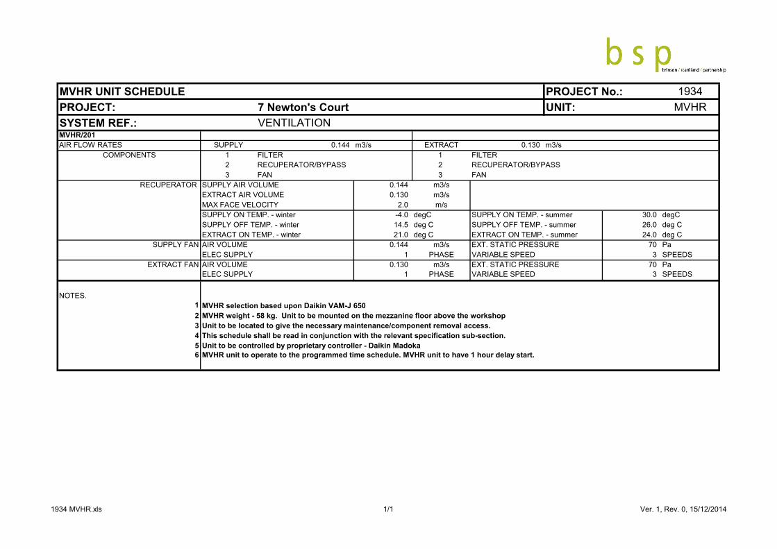
MVHR UNIT SCHEDULE PROJECT No.: 1934PROJECT: 7 Newton's Court UNIT: MVHRSYSTEM REF.: VENTILATIONMVHR/201AIR FLOW RATES SUPPLY 0.144 m3/s EXTRACT 0.130 m3/s
COMPONENTS 1 FILTER 1 FILTER2 RECUPERATOR/BYPASS 2 RECUPERATOR/BYPASS3 FAN 3 FAN
RECUPERATOR SUPPLY AIR VOLUME 0.144 m3/sEXTRACT AIR VOLUME 0.130 m3/sMAX FACE VELOCITY 2.0 m/sSUPPLY ON TEMP. - winter -4.0 degC SUPPLY ON TEMP. - summer 30.0 degCSUPPLY OFF TEMP. - winter 14.5 deg C SUPPLY OFF TEMP. - summer 26.0 deg CEXTRACT ON TEMP. - winter 21.0 deg C EXTRACT ON TEMP. - summer 24.0 deg C
SUPPLY FAN AIR VOLUME 0.144 m3/s EXT. STATIC PRESSURE 70 PaELEC SUPPLY 1 PHASE VARIABLE SPEED 3 SPEEDS
EXTRACT FAN AIR VOLUME 0.130 m3/s EXT. STATIC PRESSURE 70 PaELEC SUPPLY 1 PHASE VARIABLE SPEED 3 SPEEDS
NOTES.1 MVHR selection based upon Daikin VAM-J 6502 MVHR weight - 58 kg. Unit to be mounted on the mezzanine floor above the workshop 3 Unit to be located to give the necessary maintenance/component removal access.4 This schedule shall be read in conjunction with the relevant specification sub-section.5 Unit to be controlled by proprietary controller - Daikin Madoka 6 MVHR unit to operate to the programmed time schedule. MVHR unit to have 1 hour delay start.
1934 MVHR.xls 1/1 Ver. 1, Rev. 0, 15/12/2014

RADIATOR SCHEDULE 1934PROJECT: 7 NEWTON'S COURT RSYSTEM REF.: LTHW
ROOM ROOM ROOM ROOM No. %age HEAT FLOW ROOM/ FACTOR OUTPUT SELECTED TYPE LENGTH HEIGHT CON SPECREF. DESIGN HEAT HEAT EMITT- PER LOSS RATE EMITTER FOR FACTOR'D EMITTER REF. SIZE
TEMP. LOSS LOSS -ERS EMITTER PER PER DELTA DELTA FOR CATAL.B/F INC. FOR EMITTER EMITTER T. T. DELTA T OUTPUT (mm)
- MARGIN STAT'D DELTA T (overall(°C) (W) %age (W) (kg/s) (°C) =50°C =50°C (mm) high) (mm)
R01 GF OFFICE 21 1520 1672 1 100 1672 0.020 39 0.748 2235 2234 K1 2000 700 15 A
Flow Water Temperature (°C) 70Return Water Temperature (°C) 50Mean Water Temperature (°C) 60 TEST PRESSURE (bar gauge) 6.0
SPEC. A STEEL PANEL RADIATORS WITH WELDED SEAMS.POWDER COATED FINISH TO RAL 9016 - WHITE COLOUR WITH MANUAL T.R.V. ON FLOWCONNECTION AND L.S. REGULATING VALVE ON RETURN CONNECTION. B.O.E CONNECTIONS.TYPE: Compact HorizontalMANUFACTURER: Stelrad
UNIT:PROJECT No.:
EMITTER REF.
1/1 06/08/2021

SUPPLY DIFFUSER SCHEDULE PROJECT No.: 1934PROJECT: 7 Newton's Court UNIT: SDSYSTEM REF.: DUCT
REF: ASSOCIATED TYPE AIR MAX. PRESS. THROW PLENUM SPIGOT SPECFCU L W VOL DROP DIMS DIMS
(mm) (mm) (l/s) (m) L x W x HSD 01 FCU/01 NOZZLE DIFFUSER - - 67 11 6.5c-2h 540dia x 300 H 200 DIA. ASD 02 FCU/01 NOZZLE DIFFUSER - - 67 11 6.5c-2h 540dia x 300 H 200 DIA. ASD 03 FCU/01 NOZZLE DIFFUSER - - 67 11 6.5c-2h 540dia x 300 H 200 DIA. ASD 04 FCU/02 NOZZLE DIFFUSER - - 50 6 6.5c-2h 540dia x 300 H 200 DIA. ASD 05 FCU/02 NOZZLE DIFFUSER - - 50 6 6.5c-2h 540dia x 300 H 200 DIA. ASD 06 FCU/02 NOZZLE DIFFUSER - - 50 6 6.5c-2h 540dia x 300 H 200 DIA. ASD 07 FCU/02 NOZZLE DIFFUSER - - 50 6 6.5c-2h 540dia x 300 H 200 DIA. A
SPEC. A Circular exposed diffuser with integral volume control damper, measuring device and indivdually adjustible nozzles.Steel Construction with ABS plastic nozzles, polyester powder finish to 9010. Contractor to confirm colour reference with Architect prior to order. Manufacturer: Lindab; Model DCS-200
NOTES. 1 Contractor to request diffuser colour reference from Contract Administrator prior to order.2 Throws based upon a terminal velocity of 0.25m/s.3 Contractor is to coordinate the final fixing details and setting out for comment by the Engineer and Architect, prior to installation.
NECK SIZE
1934 SD.xls 1/1 Ver. 1, Rev. 0, 15/12/2014

1934 – 7 Newton’s Court Section 8 Page 1 August 2021
SECTION 8
ELECTRICAL SCHEDULES
NOTES TO SCHEDULES SCHEDULE 1 - SCHEDULE OF LUMINAIRES SCHEDULE 2 - SCHEDULE OF MANUFACTURERS AND SPECIALISTS SCHEDULE 3 - MOUNTING HEIGHT SCHEDULE SCHEDULE 4 – DISTRIBUTION BOARD SCHEDULES

1934 – 7 Newton’s Court Section 8 Page 2 August 2021
NOTES TO SCHEDULES
The manufacturers and references specified within these schedules set the standard for the quality and type of materials to be used, which shall be to those manufacturers’ and specialists’ normal specification and as such shall be included in the Contractors tender submission.
The inclusion of a particular name does not indicate that the supplier has been given full, partial or any details regarding this project. The tenderer should ensure that quotations obtained are for the actual equipment, delivery periods and other conditions required for the project as indicated on the drawings and within this specification. The contractor shall not rely on any quotation raised by the engineer during the design period. No claim will be entertained into on this basis.
Where the Contractor proposes alternatives, these must be declared at Tender Stage and identified separately in the Contractor’s Tender submission as proposals.
Alternatives will not be accepted unless there is seen to be an advantage to the Employer and may be rejected at the Employer’s discretion. The contractor is to provide full technical and financial details of any and all alternative suppliers with their tender return documentation. No claim shall be entered into should the contractor install an alternative, without first obtaining written approval for said alternative, and the equipment fail to meet the requirements of this specification (in any shape or form) or physically fit within the space provided.
The Contractor shall be responsible for the correct selection of equipment from the chosen manufacturers. Should the Contractor foresee any difficulty with the delivery periods for the selected equipment, this shall be clearly stated and evidence provided during the tender submission, as no unsubstantiated claims for programme delays will be accepted at a later date.
The Contractor shall obtains samples of each and every item of principal equipment (luminaires, electrical accessories etc.) for approval prior to ordering the all items required for the project.
All Luminaires shall be provided complete with necessary control gear, lamps (and where required) emergency battery packs, supports, brackets, fixings & where required fire hoods (or fire rated boxing) and all other components necessary to provide a complete and working installation. The lighting Installation shall be commissioned in accordance with CIBSE Commissioning Code L.

1934 – 7 Newton’s Court Section 8 Page 3 August 2021
SCHEDULE 1 – SCHEDULE OF LUMINAIRES
REFERENCE DESCRIPTION
MANUFACTURER’S DETAILS
A
Surface mounted linear batten luminaire with opal diffuser 1500mm long with 35W 4000deg. K LED, complete with driver
Luceco Academy range
A/E As type A with integral 3Hr battery/inverter emergency pack
B Surface mounted linear batten luminaire with opal diffuser 1500mm long with 25W 4000deg. K LED, complete with driver
Luceco Academy range
B/E As type B with integral 3Hr battery/inverter emergency pack
C Not used
D/E Circular recessed downlight, white bezel 30W LED 4000deg.K, with integral 3Hr battery/inverter emergency pack
Ovia Lighting Inceptor Iona range (to match existing)
EXIT Suspended illuminated exit sign, maintained with 3Hr integral battery/inverter unit 4000deg.K LED. Direction arrow to suit location
Ovia Lighting Hanex range (to match existing)
NB: All emergency luminaires or integral battery/inverter packs to be of the self-testing type

1934 – 7 Newton’s Court Section 8 Page 4 August 2021
SCHEDULE 2 – SCHEDULE OF MANUFACTURERS AND SPECIALISTS MANUFACTURER/EQUIPMENT/SPECIALIST TYPE/RANGE MCB Distribution Board (Existing) Schnieder Acti9 Isobar Range Isolators/Switches/Fuse-Switches Schnieder MGF Fusegear Range Power Cables Prysmian Ltd BASEC LSOH approved Range Cable Cleats, Fixings, Terminations Bi-Con (Prysmian) Multicleat / Multistrap Range
E1W Weatherproof Gland Range Wiring Cables Prysmian BASEC LSOH approved Range Cat6 Cabling Excel Networking Unscreened (U/UTP) LSOH Range Cable Management Legrand Cablofil Cable Basket
Salmandre Cable Trunking Swifts Medium duty Range
Conduit Tamlex Heavy gauge welded steel conduits Dado Trunking Marshall Tufflex Stirling range Profile 3 Data Cable Matting Marshall Tufflex Cablelay Matting Range Electrical Accessories MK Electric Logic Plus Range (general use)
Metal Clad Range (warehouse and Plant areas) Commando range (IT Rack)
Fire Detection And Alarm System Kentec/Hochiki As existing FireAlarms System Cabling Prysmian FP200 Gold IT Equipment Rack Excel Networking Environ ER800 Range

1934 – 7 Newton’s Court Section 8 Page 5 August 2021
SCHEDULE 2 – SCHEDULE OF MANUFACTURERS AND SPECIALISTS (Cont’d) MANUFACTURER/EQUIPMENT/SPECIALIST TYPE/RANGE

1934 – 7 Newton’s Court Section 8 Page 6 August 2021
SCHEDULE 2 – SCHEDULE OF MANUFACTURERS AND SPECIALISTS (Cont’d) The Contractor shall obtain quotations directly from the specialists identified within this schedule to provide the specialist system detailed within the specification section 6 and as scheduled below. Access Control & Security Systems Specialist Thompson Electrical – Shaun Bensley m. 07979 803776 [email protected] Fire Detection and Alarm Contractor to select IT Installation Specialist Contractor to select

1934 – 7 Newton’s Court Section 8 Page 7 August 2021
SCHEDULE 3 - MOUNTING HEIGHTS The Contractor shall comply with the requirements of Approved Document M of the Building Regulation. The heights given below are indicative and are to the centre line of the device. Exact locations of all accessories and equipment shall be agreed on site with the Architect. Description
Mounting height in mm Above Finished Floor Level (AFFL) unless otherwise stated
Light switches and lighting control plates: 1150
Socket outlets: 450 to underside when not in dado trunking.
150 above worktops
Data outlets: General - heights as socket outlets
Dado trunking: As directed by Architect
Door release push button unit and proximity readers: As light switches
Sounders (where not integral with detector): 2200 (min. 200 below soffits)
Xenon beacons (where not integral with detector): 2200 (min. 200 below soffits)
Fire Alarm Manual Call Point: 1200 to top
High level: 2200AFFL or 200 below finished ceiling unless otherwise stated

1934 – 7 Newton’s Court Section 8 Page 8 August 2021
SCHEDULE 4 BRINSON STANILAND PARTNERSHIP
DISTRIBUTION BOARD SCHEDULE REF: DB1 - Existing PROJECT: Newtons Court
LOCATION: Electrical Switchcupboard SIZE & TYPE: 12 way Type B MCB Distribution Board with Integral Isolator
SERVING: Lighting & Small Power PROTECTION: 100A TP HRC Fuses
CCT REF
DEVICE RATING (Amps)
CABLE SIZE
(mm²)
CPC SIZE
(mm²) CIRCUIT DESCRIPTION CABLE TYPE CIRCUIT
TYPE
1L1 6 1.5 1.5 Warehouse High Bay lighting (Existing to remain. Replace RCBO) FP200 Lighting
1L2 6 1.5 1.5 Warehouse High Bay lighting (Existing to remain. Replace RCBO) FP200 Lighting
1L3 6 1.5 1.5 Warehouse High Bay lighting (Existing to remain. Replace RCBO) FP200 Lighting
2L1 6 1.5 1.0 WC Lighting and Dis Call System (Existing to remain. Replace RCBO) PVC/PVC Lighting
2L2 6 1.5 1.0 Entrance Lobby & Stair Lighting (Existing to remain. Replace RCBO) PVC/PVC Lighting
2L3 6 1.5 1.0 First Floor Offices Lighting
(Existing circuit reallocated. Replace RCBO)
PVC/PVC Lighting
3L1 16 2.5 2.5 Disabled WC Hand Drier (Existing circuit reallocated) PVC Radial
3L2 6 1.5 1.5 Warehouse TwinSpot Emergency lighting (Existing to remain) PVC Lighting
3L3 32 2.5 1.5 First Floor offices Socket Outlets (Existing circuit reallocated) PVC/PVC Ring
4L1 16 2.5 2.5 WC Hand Drier (Existing circuit reallocated) PVC Radial
4L2 16 2.5 1.5 Entrance Lobby socket outlets and
door entry system PSU (Existing circuit reallocated)
PVC/PVC Radial
4L3
5L1
5L2 32 2.5 1.5 Ground Floor Office Socket Outlets LSOH Ring
5L3
6L1 6 2.5 1.5 Workshop LSOH Lighting
6L2 32 2.5 1.5 Kitchen Power Supplies & Socket Outlets LSOH Ring
6L3 6 2.5 1.5 Workshop LSOH Lighting

1934 – 7 Newton’s Court Section 8 Page 9 August 2021
SCHEDULE 5 BRINSON STANILAND PARTNERSHIP
DISTRIBUTION BOARD SCHEDULES REF: DB1 - Existing PROJECT: Newtons Court
LOCATION: Electrical Switchcupboard SIZE & TYPE: 12 way Type B MCB Distribution Board with Integral Isolator
SERVING: Lighting & Small Power PROTECTION: 100A TP HRC Fuses
CCT REF
DEVICE RATING (Amps)
CABLE SIZE
(mm²)
CPC SIZE
(mm²) CIRCUIT DESCRIPTION CABLE TYPE CIRCUIT
TYPE
7L1 20 2.5 1.5 Workbench Socket Outlets LSOH Radial
7L2 20 2.5 1.5 Workbench Socket Outlets LSOH Radial
7L3 20 2.5 1.5 Workbench Socket Outlets LSOH Radial
8L1 20 2.5 1.5 Workbench Socket Outlets LSOH Radial
8L2 20 2.5 1.5 Workbench Socket Outlets LSOH Radial
8L3 20 2.5 1.5 Workbench Socket Outlets LSOH Radial
9L1 20 2.5 1.5 Workbench Socket Outlets LSOH Radial
9L2 20 2.5 1.5 Workbench Socket Outlets LSOH Radial
9L3 20 2.5 1.5 Workbench Socket Outlets LSOH Radial
10L1 ) )
10L2 ) 10 2.5 2.5 Roller Shutter (Existing to remain) PVC Radial
10L3 ) )
11L1 20 2.5 1.5 Workbench Socket Outlets LSOH Radial
11L2 20 2.5 1.5 Workbench Socket Outlets LSOH Radial
11L3 20 2.5 1.5 Workbench Socket Outlets LSOH Radial
12L1 32 2.5 1.5 Workshop Perimeter Socket Outlets LSOH Ring
12L2 32 2.5 1.5 Workshop Perimeter Socket Outlets LSOH Ring
12L3 32 2.5 1.5 Workshop Perimeter Socket Outlets LSOH Ring

1934 – 7 Newton’s Court Section 8 Page 10 August 2021
SCHEDULE 5 BRINSON STANILAND PARTNERSHIP
DISTRIBUTION BOARD SCHEDULES REF: DB1 - Existing PROJECT: Newtons Court
LOCATION: Electrical Switchcupboard SIZE & TYPE: 12 way Type B MCB Distribution Board with Integral Isolator
SERVING: Lighting & Small Power PROTECTION: 100A TP HRC Fuses
CCT REF
DEVICE RATING (Amps)
CABLE SIZE
(mm²)
CPC SIZE
(mm²) CIRCUIT DESCRIPTION CABLE TYPE CIRCUIT
TYPE
13L1 32 4.0 2.5 IT Equipment Rack LSOH Radial
13L2 6 2.5 1.5 Ground floor Office, kitchen Switchroom & Cleaners Cup’d LSOH Lighting
13L3 32 4.0 SWA External Heat Pump Condenser Unit XLPE/SWA/LSF Radial
14L1
14L2 16 2.5 1.5 Heating System (existing to remain) PVC/PVC Radial
14L3 10 1.5 1.5 WC Extract fan & Kitchen
Extract fan (existing to remain/extended)
PVC Radial
15L1 6 Spare
15L2 6 Spare
15L3 20 Spare
16L1 10 2.5 2.5 Fire alarm system (existing to remain) FP200 Radial
16L2 20 Spare
16L3 32 Spare
17-19 32 Spare
20L1 ) )
20L2 ) 40 10.0 10.0 Surge Protection Unit (Existing to remain) PVC Radial
20L3 ) )

QA/BSP 44-08/15 1934 - 7 Newton’s Court Section 9/Page 1 August 2021
SECTION 9
SCHEDULE OF DRAWINGS

QA/BSP 44-08/15 1934 - 7 Newton’s Court Section 9/Page 2 August 2021
SECTION 9
SCHEDULE OF DRAWINGS
DRAWING TITLE DRAWING No.
Mechanical Systems Ground Floor Mechanical Systems 1934-M200
First Floor Mechanical Systems 1934-M201
Electrical Systems
Ground Floor Electrical Systems 1934-E200
First Floor Electrical Systems 1934-E201

QA/BSP 45-08/15 1934 – 7 Newton’s Court Section 10/Page 1 August 2021
SECTION 10
PRICING SCHEDULES

QA/BSP 45-08/15 1934 – 7 Newton’s Court Section 10/Page 2 August 2021
TENDER SUMMARY
MECHANICAL a) Engineering Preambles £……………….. b) Builders’ Work (including fire stopping) £……………….. c) Mechanical Ventilation Systems £……………….. d) Heating and Comfort Cooling Systems £……………….. e) Heating Systems £……………….. f) Domestic Water Systems £……………….. g) Soil and Waste Systems £……………….. h) Testing, Commissioning & Demonstrations £……………….. i) 12 Months Maintenance £……………….. j) Builders’ Work (including fire stopping) £……………….. k) 12 Months Maintenance £……………….. l) O&M Documentation £……………….. m) Provisional sum – Additional sound attenuation provisions for
mechanical systems in the workshop £2,500.00
MECHANICAL £……………….. ELECTRICAL a) Engineering Preambles £……………….. b) LV Distribution £……………….. c) Containment Systems £……………….. d) Lighting & Emergency Lighting £……………….. e) Small Power Installations £……………….. f) Power Supplies to Mechanical Systems £……………….. g) Fire Detection and Alarm System £……………….. h) Voice and Data System £……………….. i) Access Control System £……………….. j) CCTV System £……………….. k) Intruder Detection System £……………….. l) Earthing and Bonding £……………….. m) Testing, Commissioning & Demonstrations £……………….. n) Builders’ Work (including fire stopping) £……………….. o) 12 Months Maintenance £……………….. p) O&M Documentation £……………….. q) Provisional sum for Additional Workshop Power/Data requirements £2,000.00 ELECTRICAL £……………….. TOTAL MECHANICAL AND ELECTRICAL £………………..
QA/BSP 45-08/15 1934 – 7 Newton’s Court Section 10/Page 3 August 2021
10.2 SCHEDULES OF PROPOSED SUB-CONTRACTORS & SUPPLIERS The Tenderer shall list below all specialists and other sub-contractors to whom he proposes to sub-let part(s) of the Sub-Contract Works, subject to the approval of the Contract Administrator before commencement of the Works.
Description of Work Proposed to be Sub-Let
Name and Address of Sub-Contractor