fluid typing in thinly bedded reservoirs th offshore ... typing in thinly bedded reservoirs 10th...
TRANSCRIPT

Fluid Typing In Thinly Bedded Reservoirs
10th Offshore Mediterranean Conference – OMCRavenna, Italy, March 2011
R l d Ch liRoland ChemaliChief Petrophysicist Sperry Drilling
Maged FamHalliburton Technology Manager
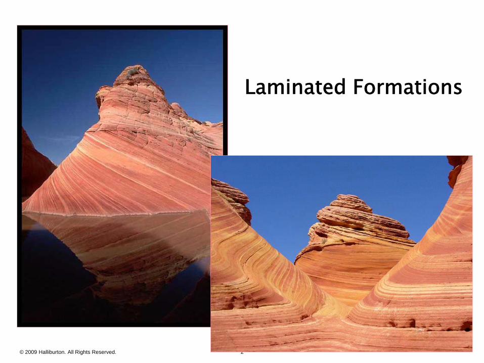
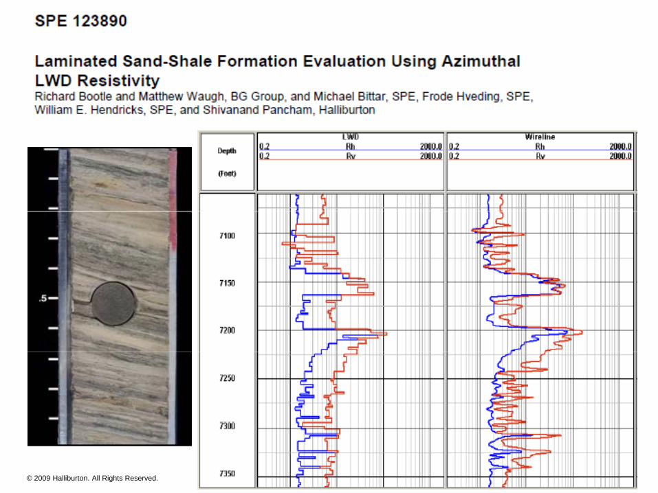
Laminated Formations
RvRhRh
© 2009 Halliburton. All Rights Reserved. 2
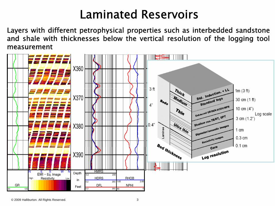
Laminated ReservoirsLayers with different petrophysical properties such as interbedded sandstoneLayers with different petrophysical properties such as interbedded sandstoneand shale with thicknesses below the vertical resolution of the logging toolmeasurement
© 2009 Halliburton. All Rights Reserved. 3
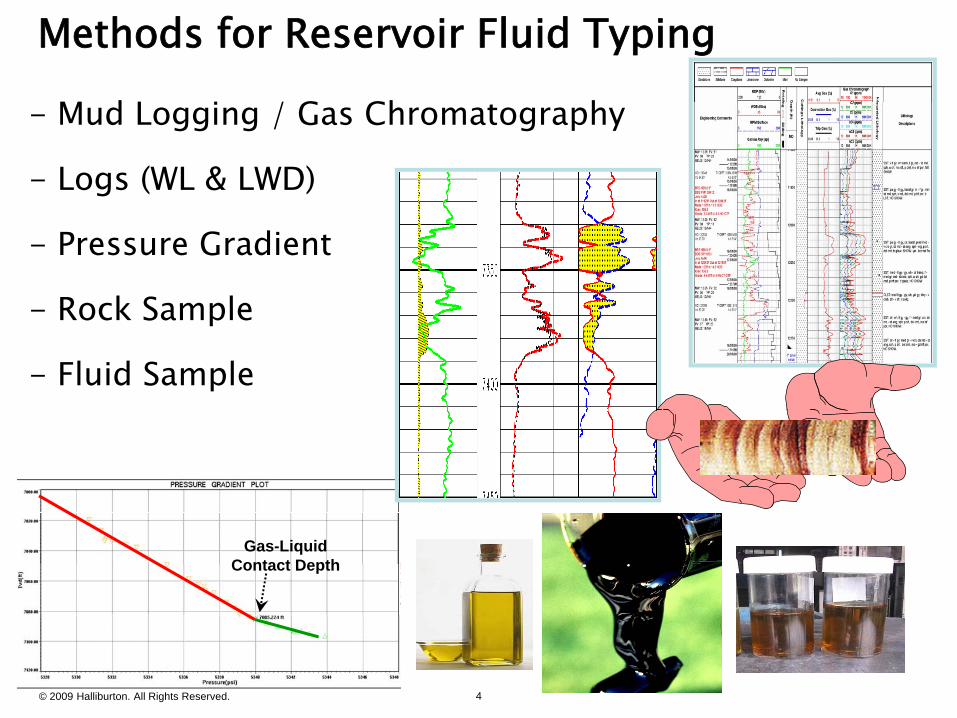
Methods for Reservoir Fluid Typing
M d L i / G Ch h- Mud Logging / Gas Chromatography
- Logs (WL & LWD)
- Pressure Gradient
Rock Sample- Rock Sample
- Fluid Sample
Gas-Liquid Contact Depth
© 2009 Halliburton. All Rights Reserved. 4
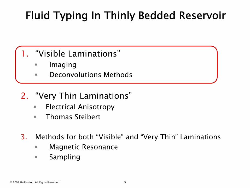
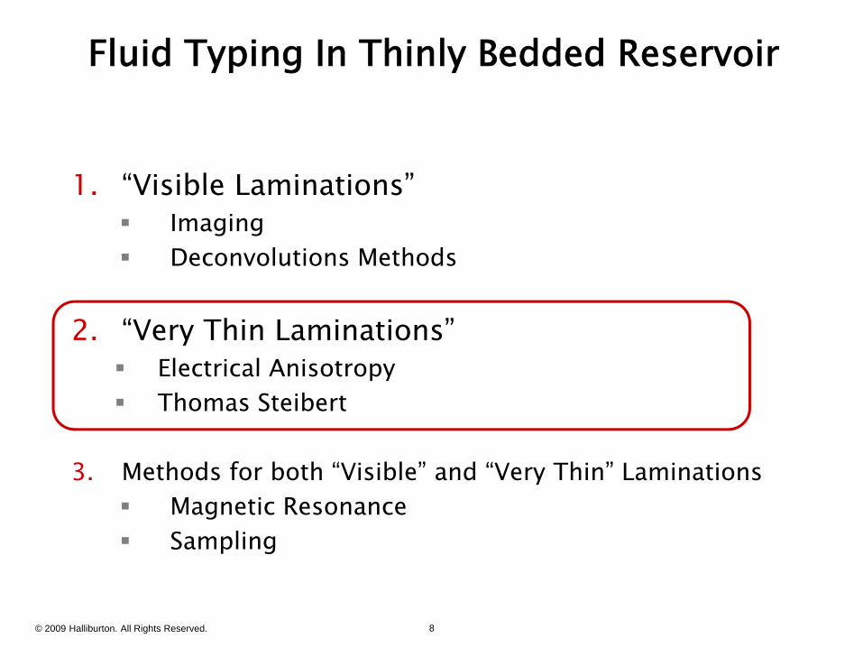
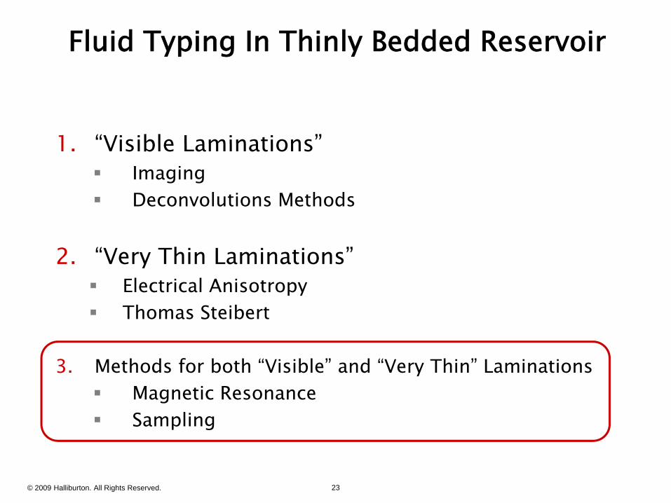
Fluid Typing In Thinly Bedded Reservoir
1 “Visible Laminations”1. Visible Laminations Imaging Deconvolutions Methods
2. “Very Thin Laminations” Electrical Anisotropy Electrical Anisotropy Thomas Steibert
3 h d f b h “ bl ” d “ h ”3. Methods for both “Visible” and “Very Thin” Laminations Magnetic Resonance Sampling
© 2009 Halliburton. All Rights Reserved. 5
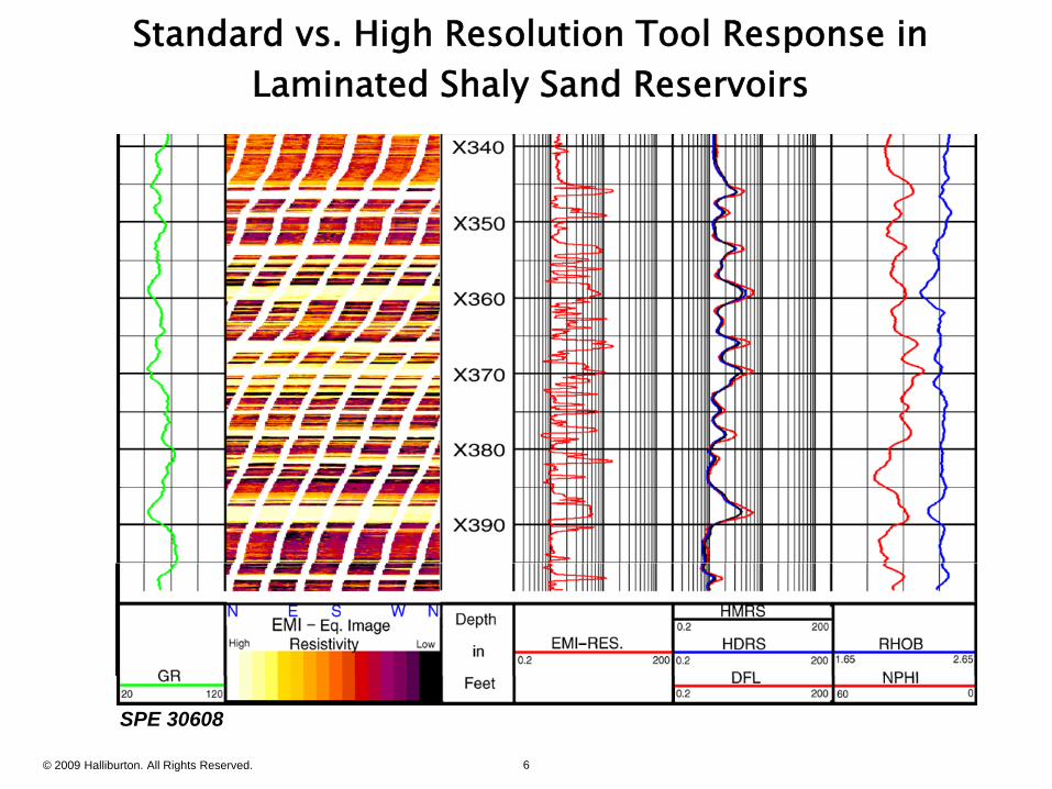
Standard vs. High Resolution Tool Response in Laminated Shaly Sand Reservoirs
© 2009 Halliburton. All Rights Reserved. 6
SPE 30608
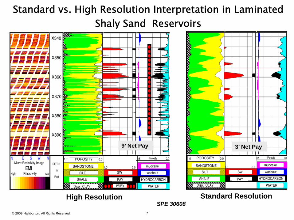
Standard vs. High Resolution Interpretation in Laminated Shaly Sand Reservoirs
3’ Net Pay3’ Net Pay9’ Net Pay9’ Net Pay
© 2009 Halliburton. All Rights Reserved. 7
Standard ResolutionHigh ResolutionSPE 30608
Fluid Typing In Thinly Bedded Reservoir
1 “Visible Laminations”1. Visible Laminations Imaging Deconvolutions Methods
2. “Very Thin Laminations” Electrical Anisotropy Electrical Anisotropy Thomas Steibert
3 h d f b h “ bl ” d “ h ”3. Methods for both “Visible” and “Very Thin” Laminations Magnetic Resonance Sampling
© 2009 Halliburton. All Rights Reserved. 8
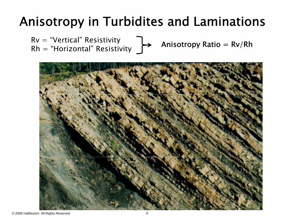
Anisotropy in Turbidites and LaminationsRv = “Vertical” ResistivityRh = “Horizontal” Resistivity Anisotropy Ratio = Rv/Rh
RvRRh
© 2009 Halliburton. All Rights Reserved. 9
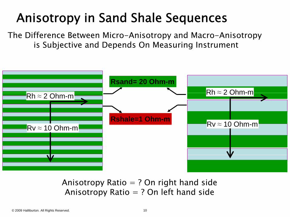
Anisotropy in Sand Shale SequencesThe Difference Between Micro-Anisotropy and Macro-Anisotropy
is Subjective and Depends On Measuring Instrument
Rsand= 20 Ohm-mRh ≈ 2 Ohm-m
Rshale=1 Ohm-m
Rh ≈ 2 Ohm-m
Rv ≈ 10 Ohm m
Rh ≈ 2 Ohm-m
Rv ≈ 10 Ohm-m Rv ≈ 10 Ohm-m
Anisotropy Ratio = ? On right hand side
© 2009 Halliburton. All Rights Reserved. 10
py gAnisotropy Ratio = ? On left hand side
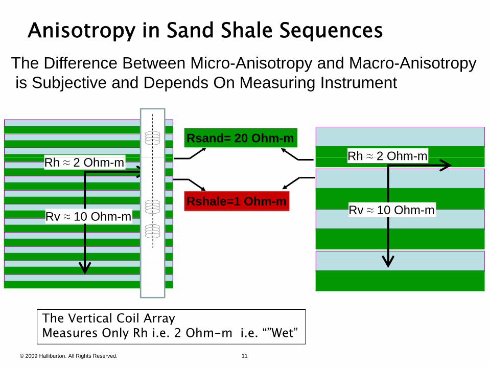
Anisotropy in Sand Shale SequencesThe Difference Between Micro-Anisotropy and Macro-Anisotropyis Subjective and Depends On Measuring Instrument
Rsand= 20 Ohm-mRh ≈ 2 Ohm-m
Rshale=1 Ohm-m
Rh ≈ 2 Ohm-m
Rv ≈ 10 Ohm m
Rh ≈ 2 Ohm-m
Rv ≈ 10 Ohm-m Rv ≈ 10 Ohm-m
Th V i l C il A
© 2009 Halliburton. All Rights Reserved. 11
The Vertical Coil ArrayMeasures Only Rh i.e. 2 Ohm-m i.e. “”Wet”
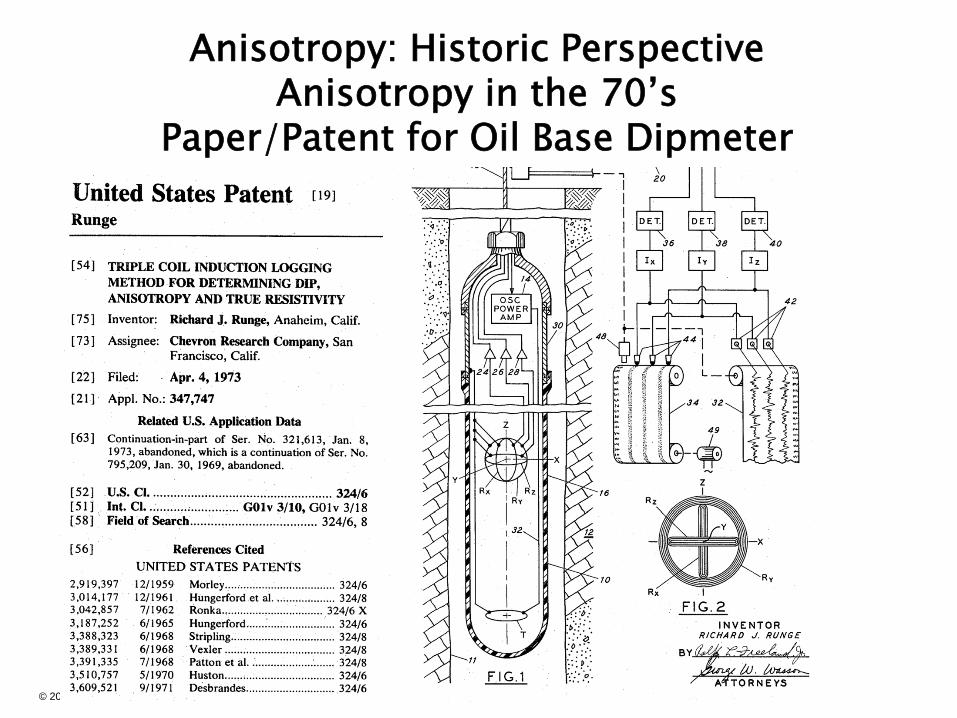
Anisotropy: Historic PerspectiveAnisotropy in the 70’sAnisotropy in the 70 s
Paper/Patent for Oil Base Dipmeter
© 2009 Halliburton. All Rights Reserved. 12

Anisotropy: Historic Perspective
Anisotropy in the 80’sExplains Separation Between Induction and Laterolog
A Nuisance to Contend WithA Nuisance to Contend With
© 2009 Halliburton. All Rights Reserved. 13
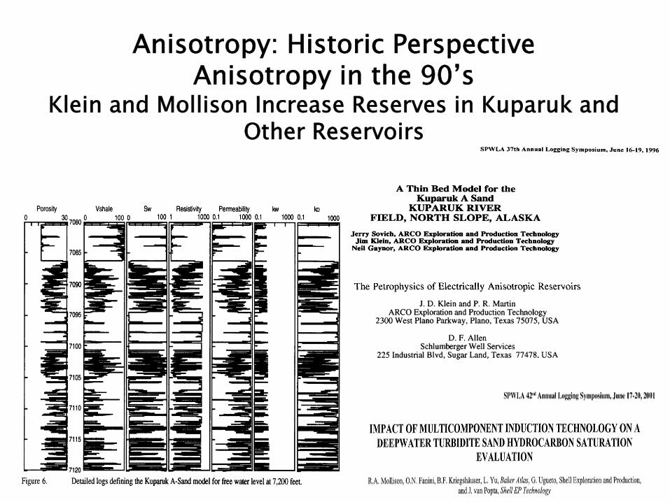
Anisotropy: Historic PerspectiveAnisotropy in the 90’sAnisotropy in the 90 s
Klein and Mollison Increase Reserves in Kuparuk and Other Reservoirs
© 2009 Halliburton. All Rights Reserved. 14
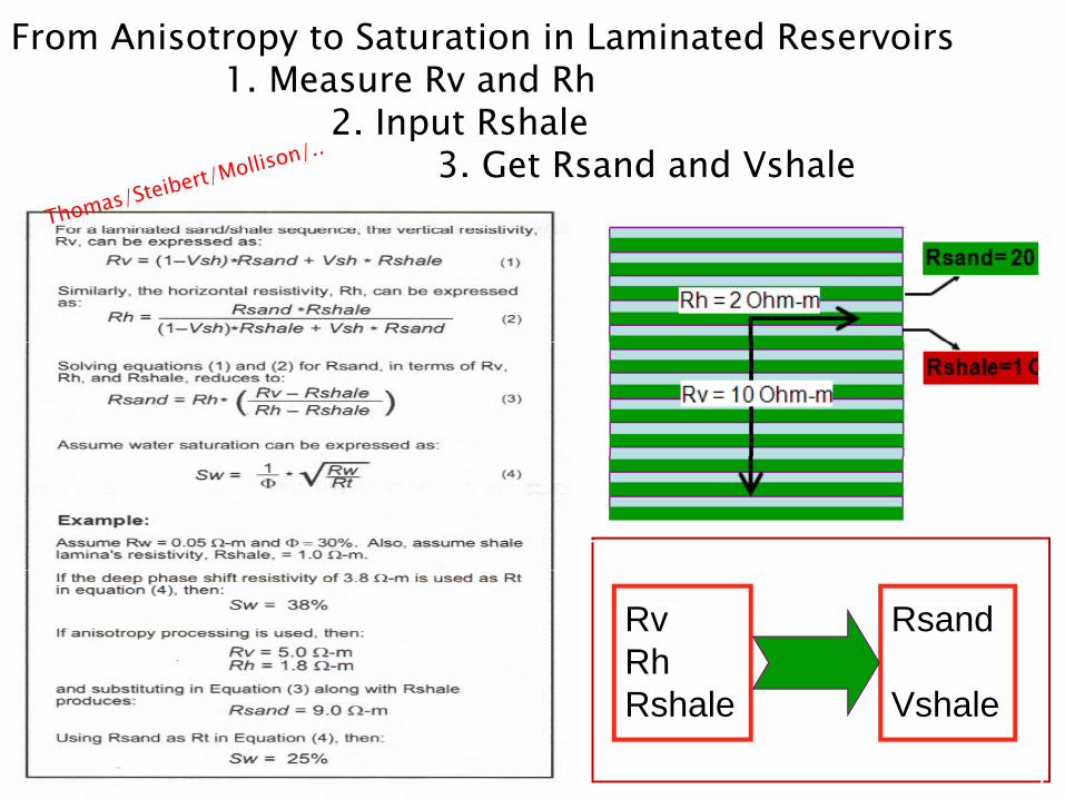
From Anisotropy to Saturation in Laminated Reservoirs1. Measure Rv and Rh
2 I t R h l2. Input Rshale3. Get Rsand and Vshale
RvRh
Rsand
© 2009 Halliburton. All Rights Reserved. 15
Rshale Vshale
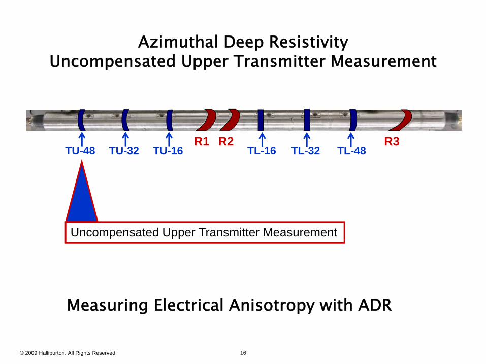
Azimuthal Deep ResistivityUncompensated Upper Transmitter Measurement
TL-16 TL-32 TL-48R1 R2 R3
TU-48 TU-32 TU-16
3 x Receivers
Uncompensated Upper Transmitter Measurement
Measuring Electrical Anisotropy with ADR
© 2009 Halliburton. All Rights Reserved. 16
g py
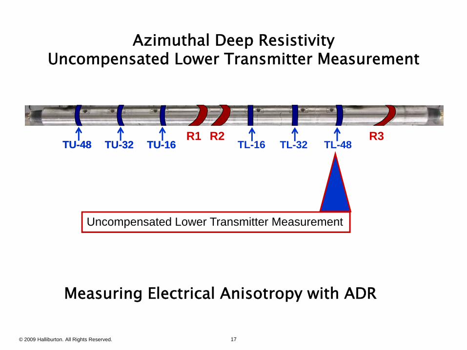
Azimuthal Deep ResistivityUncompensated Lower Transmitter Measurement
TU-48 TU-32 TU-16 TL-16 TL-32 TL-48R1 R2 R3
TU-48 TU-32 TU-16
Uncompensated Lower Transmitter Measurement
Measuring Electrical Anisotropy with ADR
© 2009 Halliburton. All Rights Reserved. 17
g py
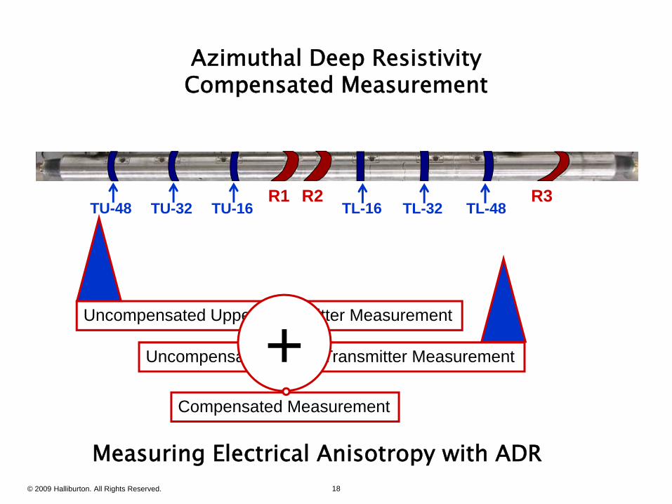
Azimuthal Deep ResistivityCompensated Measurement
TU-48 TU-32 TU-16 TL-16 TL-32 TL-48R1 R2 R3
Uncompensated Upper Transmitter Measurement
Uncompensated Lower Transmitter Measurement+Uncompensated Lower Transmitter Measurement+Compensated Measurement
© 2009 Halliburton. All Rights Reserved. 18
Measuring Electrical Anisotropy with ADR
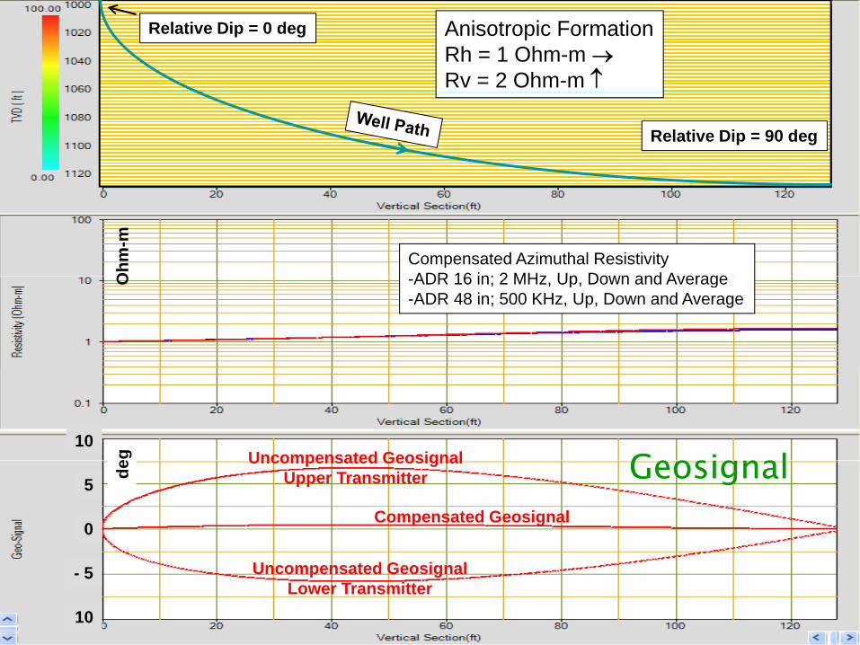
Anisotropic FormationRh = 1 Ohm-m Rv = 2 Ohm-m
Relative Dip = 0 deg
Relative Dip = 90 deg
Compensated Azimuthal ResistivityADR 16 in; 2 MHz Up Down and AverageO
hm-m
-ADR 16 in; 2 MHz, Up, Down and Average-ADR 48 in; 500 KHz, Up, Down and Average
O
Uncompensated Geosignal10
eg GeosignalUncompensated GeosignalUpper Transmitter
Compensated Geosignal
5
0
de Geosignal
© 2009 Halliburton. All Rights Reserved. 19
Uncompensated GeosignalLower Transmitter
- 5
10

Anisotropic FormationRh = 1 Ohm-m Rv = 3 Ohm-m
Relative Dip = 0 deg
Relative Dip = 90 deg
Compensated Azimuthal ResistivityADR 16 in; 2 MHz Up Down and AverageO
hm-m
-ADR 16 in; 2 MHz, Up, Down and Average-ADR 48 in; 500 KHz, Up, Down and Average
O
Uncompensated GeosignalU T itt
10
eg GeosignalUpper Transmitter
Compensated Geosignal
5
0
de Geosignal
© 2009 Halliburton. All Rights Reserved. 20
Uncompensated GeosignalLower Transmitter
- 5
10
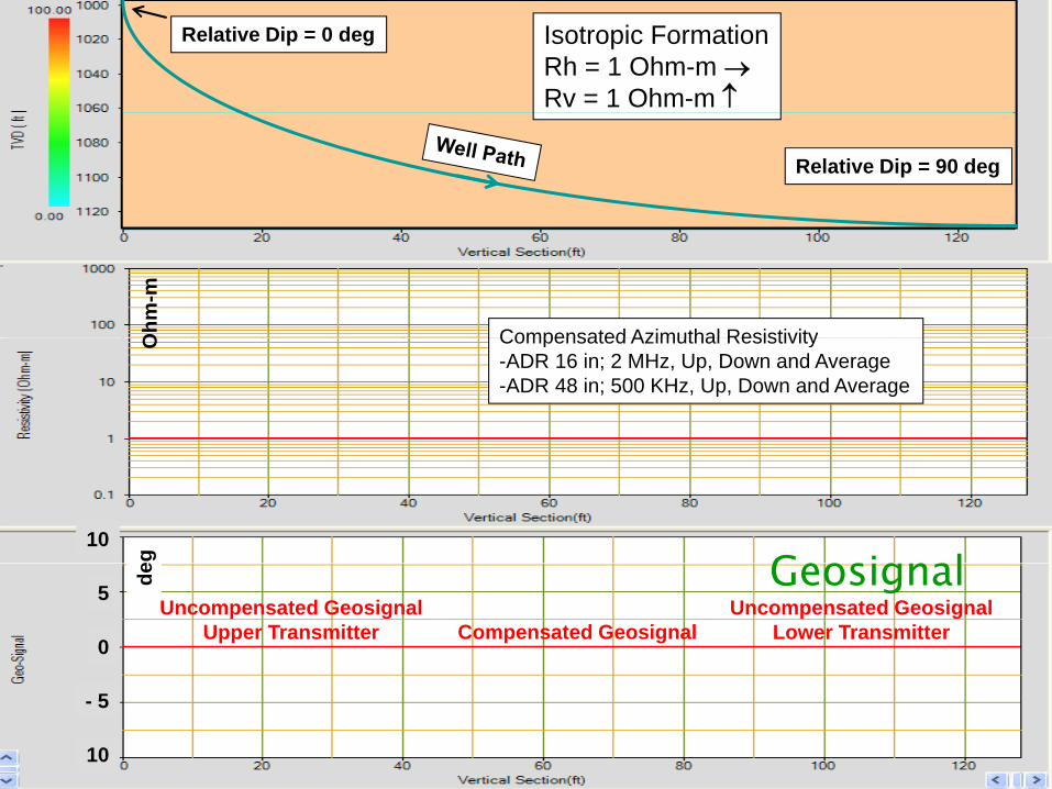
Isotropic FormationRh = 1 Ohm-m Rv = 1 Ohm-m
Relative Dip = 0 deg
Relative Dip = 90 deg
Compensated Azimuthal ResistivityOhm
-m
Compensated Azimuthal Resistivity-ADR 16 in; 2 MHz, Up, Down and Average-ADR 48 in; 500 KHz, Up, Down and Average
O
10
eg GeosignalUncompensated Geosignal
Upper TransmitterUncompensated Geosignal
Lower TransmitterCompensated Geosignal
5
0
de Geosignal
© 2009 Halliburton. All Rights Reserved. 21
- 5
10
© 2009 Halliburton. All Rights Reserved. 22
Fluid Typing In Thinly Bedded Reservoir
1 “Visible Laminations”1. Visible Laminations Imaging Deconvolutions Methods
2. “Very Thin Laminations” Electrical Anisotropy Electrical Anisotropy Thomas Steibert
3 h d f b h “ bl ” d “ h ”3. Methods for both “Visible” and “Very Thin” Laminations Magnetic Resonance Sampling
© 2009 Halliburton. All Rights Reserved. 23
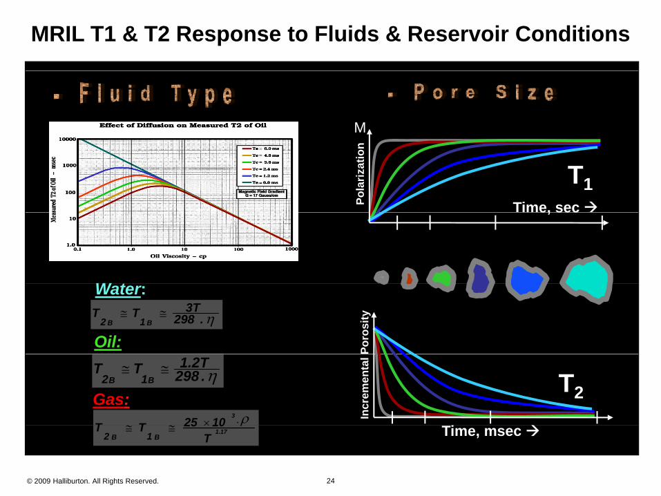
MRIL T1 & T2 Response to Fluids & Reservoir Conditions
M
Time, sec Pola
rizat
ion
T1
W t
e, sec
.2983TTT
BB 12
Water:
Oil: Poro
sity
.298
1.2TTT BB 12
Gas:1025TT
3 . Incr
emen
tal
T2
© 2009 Halliburton. All Rights Reserved. 24
T1025TT 1.17
BB 12
Time, msec
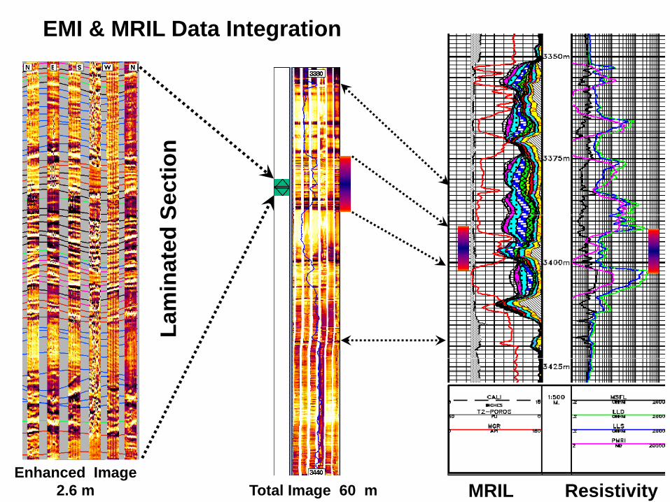
EMI & MRIL Data Integration
nSe
ctio
nna
ted
SLa
mi
© 2009 Halliburton. All Rights Reserved. 25 MRIL ResistivityTotal Image 60 mEnhanced Image
2.6 m
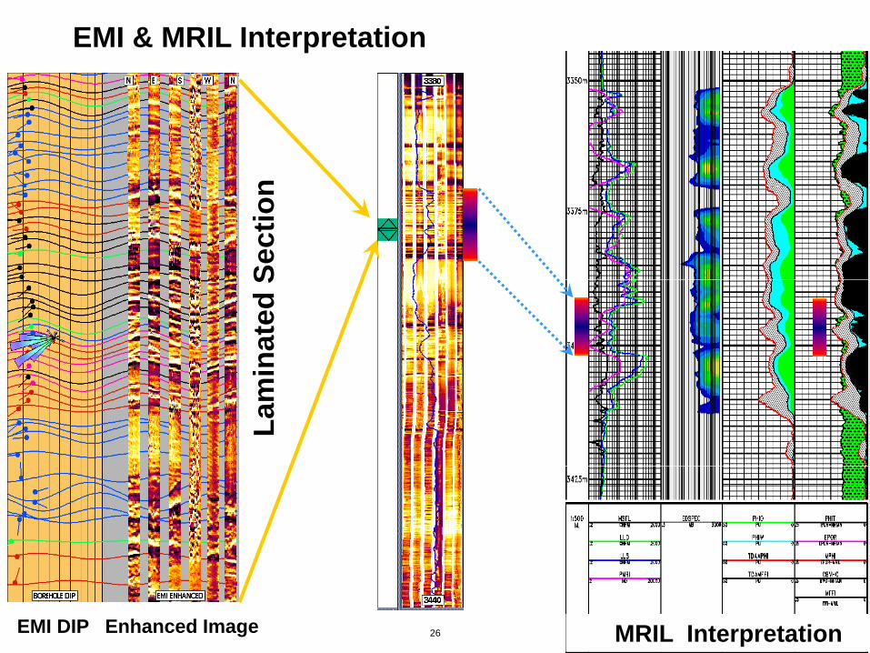
EMI & MRIL Interpretation
nSe
ctio
nin
ated
SLa
mi
© 2009 Halliburton. All Rights Reserved. 26 MRIL InterpretationEMI DIP Enhanced Image
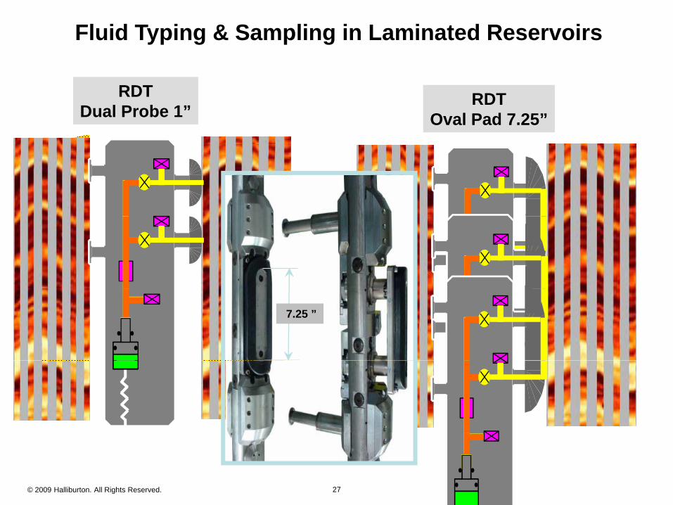
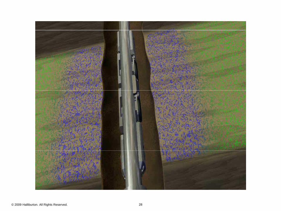
Fluid Typing & Sampling in Laminated Reservoirs
RDTDual Probe 1”
RDTDual Probe 1”
RDTOval Pad 7.25”
RDTOval Pad 7.25”
7.25 ”
© 2009 Halliburton. All Rights Reserved. 27
© 2009 Halliburton. All Rights Reserved. 28
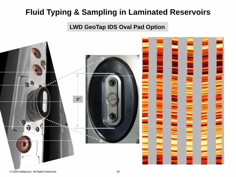
Fluid Typing & Sampling in Laminated Reservoirs
LWD G T IDS O l P d O tiLWD G T IDS O l P d O tiLWD GeoTap IDS Oval Pad OptionLWD GeoTap IDS Oval Pad Option
3”
© 2009 Halliburton. All Rights Reserved. 29
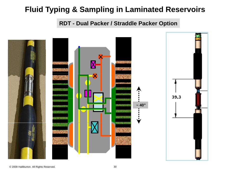
Fluid Typing & Sampling in Laminated Reservoirs
RDT - Dual Packer / Straddle Packer OptionRDT - Dual Packer / Straddle Packer OptionRDT Dual Packer / Straddle Packer OptionRDT Dual Packer / Straddle Packer Option
~ 40”
© 2009 Halliburton. All Rights Reserved. 30
Fluid Typing In Thinly Bedded Reservoir
1 “Visible Laminations”1. Visible Laminations Imaging Deconvolutions Methods
2. “Very Thin Laminations” Electrical Anisotropy Electrical Anisotropy Thomas Steibert
3 h d f b h “ bl ” d “ h ”3. Methods for both “Visible” and “Very Thin” Laminations Magnetic Resonance Sampling
© 2009 Halliburton. All Rights Reserved. 31