flight guidance system requirements specificationmln/ltrs-pdfs/nasa-2003-cr212426.pdfabstract this...
TRANSCRIPT

June 2003
NASA/CR-2003-212426
Flight Guidance System RequirementsSpecification
Steven P. Miller, Alan C. Tribble, Timothy M. Carlson, and Eric J. DanielsonRockwell Collins, Cedar Rapids, Iowa

The NASA STI Program Office . . . in Profile
Since its founding, NASA has been dedicated to theadvancement of aeronautics and space science. TheNASA Scientific and Technical Information (STI)Program Office plays a key part in helping NASAmaintain this important role.
The NASA STI Program Office is operated byLangley Research Center, the lead center for NASA’sscientific and technical information. The NASA STIProgram Office provides access to the NASA STIDatabase, the largest collection of aeronautical andspace science STI in the world. The Program Office isalso NASA’s institutional mechanism fordisseminating the results of its research anddevelopment activities. These results are published byNASA in the NASA STI Report Series, whichincludes the following report types:
• TECHNICAL PUBLICATION. Reports of
completed research or a major significant phaseof research that present the results of NASAprograms and include extensive data ortheoretical analysis. Includes compilations ofsignificant scientific and technical data andinformation deemed to be of continuingreference value. NASA counterpart of peer-reviewed formal professional papers, but havingless stringent limitations on manuscript lengthand extent of graphic presentations.
• TECHNICAL MEMORANDUM. Scientific
and technical findings that are preliminary or ofspecialized interest, e.g., quick release reports,working papers, and bibliographies that containminimal annotation. Does not contain extensiveanalysis.
• CONTRACTOR REPORT. Scientific and
technical findings by NASA-sponsoredcontractors and grantees.
• CONFERENCE PUBLICATION. Collected
papers from scientific and technicalconferences, symposia, seminars, or othermeetings sponsored or co-sponsored by NASA.
• SPECIAL PUBLICATION. Scientific,
technical, or historical information from NASAprograms, projects, and missions, oftenconcerned with subjects having substantialpublic interest.
• TECHNICAL TRANSLATION. English-
language translations of foreign scientific andtechnical material pertinent to NASA’s mission.
Specialized services that complement the STIProgram Office’s diverse offerings include creatingcustom thesauri, building customized databases,organizing and publishing research results ... evenproviding videos.
For more information about the NASA STI ProgramOffice, see the following:
• Access the NASA STI Program Home Page athttp://www.sti.nasa.gov
• E-mail your question via the Internet to
[email protected] • Fax your question to the NASA STI Help Desk
at (301) 621-0134 • Phone the NASA STI Help Desk at
(301) 621-0390 • Write to:
NASA STI Help Desk NASA Center for AeroSpace Information 7121 Standard Drive Hanover, MD 21076-1320

National Aeronautics andSpace Administration
Langley Research Center Prepared for Langley Research CenterHampton, Virginia 23681-2199 under Cooperative Agreement NCC1-01001
June 2003
NASA/CR-2003-212426
Flight Guidance System RequirementsSpecification
Steven P. Miller, Alan C. Tribble, Timothy M. Carlson, and Eric J. DanielsonRockwell Collins, Cedar Rapids, Iowa

Available from:
NASA Center for AeroSpace Information (CASI) National Technical Information Service (NTIS)7121 Standard Drive 5285 Port Royal RoadHanover, MD 21076-1320 Springfield, VA 22161-2171(301) 621-0390 (703) 605-6000

Abstract
This report describes a requirements specification written in the RSML−e language for themode logic of a Flight Guidance System of a typical regional jet aircraft. This model was createdas one of the first steps in five-year project sponsored by the NASA Langley Research Center,Rockwell Collins Inc., and the Critical Systems Research Group of the University of Minnesota todevelop new methods and tools to improve the safety of avionics designs. This model will be usedto demonstrate the application of a variety of methods and techniques, including safety analysisof system and subystem requirements, verification of key properties using theorem provers andmodel checkers, identification of potential sources mode confusion in system designs, partitioningof applications based on the criticality of system hazards, and autogeneration of avionics qualitycode. While this model is representative of the mode logic of a typical regional jet aircraft, itdoes not describe an actual or planned product. Several aspects of a full Flight Guidance System,such as recovery from failed sensors, have been omitted, and no claims are made regarding theaccuracy or completeness of this specification.

2

Contents
1 Introduction 51.1 How Requirements Analysis Relates to Aircraft Safety . . . . . . . . . . . . . . . . 51.2 Overview of a Flight Guidance System . . . . . . . . . . . . . . . . . . . . . . . . . 91.3 Fundamentals of the Mode Logic . . . . . . . . . . . . . . . . . . . . . . . . . . . . 12
2 The FGS Requirements Specification 152.1 Overview of the FGS Specification . . . . . . . . . . . . . . . . . . . . . . . . . . . 162.2 Prioritization of Events . . . . . . . . . . . . . . . . . . . . . . . . . . . . . . . . . 202.3 Basic Definitions . . . . . . . . . . . . . . . . . . . . . . . . . . . . . . . . . . . . . 232.4 Flight Director (FD) . . . . . . . . . . . . . . . . . . . . . . . . . . . . . . . . . . . 252.5 Pilot Flying (PF) . . . . . . . . . . . . . . . . . . . . . . . . . . . . . . . . . . . . . 292.6 Independent Mode . . . . . . . . . . . . . . . . . . . . . . . . . . . . . . . . . . . . 302.7 Flight Modes . . . . . . . . . . . . . . . . . . . . . . . . . . . . . . . . . . . . . . . 32
2.7.1 Lateral Modes . . . . . . . . . . . . . . . . . . . . . . . . . . . . . . . . . . 352.7.1.1 Roll Hold (ROLL) Mode . . . . . . . . . . . . . . . . . . . . . . . 372.7.1.2 Heading Select (HDG) Mode . . . . . . . . . . . . . . . . . . . . . 402.7.1.3 Navigation (NAV) Mode . . . . . . . . . . . . . . . . . . . . . . . 442.7.1.4 Lateral Approach (LAPPR) Mode . . . . . . . . . . . . . . . . . . 502.7.1.5 Lateral Go Around (LGA) Mode . . . . . . . . . . . . . . . . . . . 56
2.7.2 Vertical Modes . . . . . . . . . . . . . . . . . . . . . . . . . . . . . . . . . . 602.7.2.1 Pitch Hold (PITCH) Mode . . . . . . . . . . . . . . . . . . . . . . 622.7.2.2 Vertical Speed (VS) Mode . . . . . . . . . . . . . . . . . . . . . . 652.7.2.3 Flight Level Change (FLC) Mode . . . . . . . . . . . . . . . . . . 692.7.2.4 Altitude Hold (ALT) Mode . . . . . . . . . . . . . . . . . . . . . . 732.7.2.5 Altitude Select (ALTSEL) Mode . . . . . . . . . . . . . . . . . . . 772.7.2.6 Vertical Approach (VAPPR) Mode . . . . . . . . . . . . . . . . . . 852.7.2.7 Vertical Go Around (VGA) Mode . . . . . . . . . . . . . . . . . . 91
2.8 Flight Control Laws . . . . . . . . . . . . . . . . . . . . . . . . . . . . . . . . . . . 952.9 Flight Control Panel (FCP) . . . . . . . . . . . . . . . . . . . . . . . . . . . . . . . 1032.10 Navigation Sources . . . . . . . . . . . . . . . . . . . . . . . . . . . . . . . . . . . . 1272.11 Air Data System . . . . . . . . . . . . . . . . . . . . . . . . . . . . . . . . . . . . . 1282.12 References . . . . . . . . . . . . . . . . . . . . . . . . . . . . . . . . . . . . . . . . . 129
3
2.13 Autopilot (AP) . . . . . . . . . . . . . . . . . . . . . . . . . . . . . . . . . . . . . . 1302.14 Offside FGS . . . . . . . . . . . . . . . . . . . . . . . . . . . . . . . . . . . . . . . . 1332.15 FGS Inputs . . . . . . . . . . . . . . . . . . . . . . . . . . . . . . . . . . . . . . . . 1522.16 FGS Outputs . . . . . . . . . . . . . . . . . . . . . . . . . . . . . . . . . . . . . . . 156References . . . . . . . . . . . . . . . . . . . . . . . . . . . . . . . . . . . . . . . . . . . . 161Index . . . . . . . . . . . . . . . . . . . . . . . . . . . . . . . . . . . . . . . . . . . . . . 163
4

Chapter 1
Introduction
This report describes a requirements specification written in the RSML−e [8, 6] language for themode logic of a Flight Guidance System of a typical regional jet aircraft. This model was createdas one of the first steps in a project sponsored by the NASA Langley Research Center, RockwellCollins, Inc., and the Critical Systems Research Group of the University of Minnesota to developnew methods and tools to improve the safety of avionics designs. This model will be used todemonstrate the application of a variety of methods and techniques, including:
• Safety analysis of system and subsystem requirements
• Verification of key properties using theorem provers and model checkers
• Identification of potential sources mode confusion in system designs
• Partitioning of applications based on the criticality of system hazards
• Autogeneration of avionics quality code
While this model is representative of the mode logic of a typical regional jet aircraft, it doesnot describe an actual or planned product. Several aspects of a full Flight Guidance System,such as recovery from failed sensors, have been omitted, and no claims are made regarding theaccuracy or completeness of this specification.
The report is organized as follows. In this chapter, Section 1.1 discusses why the modelingand analysis of requirements is important to aircraft safety, Section 1.2 provides an overview of amodern Flight Guidance System, and Section 1.3 discusses the the fundamentals of the mode logicfound in the FGS. Chapter 2 deals with the requirements specification itself. Section 2.1 describeshow the specification is organized. The remaining sections of Chapter 2 are the specification itself.
1.1 How Requirements Analysis Relates to Aircraft Safety
Aircraft safety has improved steadily over the last few decades and much of this improvementcan be attributed to the introduction of advanced automation in the cockpit. The predicted
5

6
Accident Category Fatalities Accidents
Controlled Flight Into Terrain 2111 28Loss of Control in Flight 2011 29In Flight Fire 600 3Midair Collision 506 2Fuel Tank Explosion 238 2Landing ∼200 14Takeoff ∼144 3Ice/Snow ∼60 3Fuel Exhaustion ∼40 5Wind Shear ∼30 2Runway Incursion ∼10 4Misc. Fatality ∼10 3On Ground ∼10 3Refused Takeoff ∼10 1Turbulence ∼10 3Unknown 482 7
Total 6465 112
Table 1.1: Fatal Accidents - Worldwide Commercial Jet Fleet, 1990-1999 - From [14]
ten-fold increase in air traffic by 2016 will force much greater reliance on automated systems.New technologies, such as: Communication, Navigation, and Surveillance for Air Traffic Manage-ment (CNS/ATM); Global Air Traffic Management (GATM); Global Positioning System (GPS);and fly-by-wire, will be introduced to meet enhanced safety and performance goals. Table 1.1classifies the fatal accidents of the worldwide commercial jet fleet for the period of 1990 to 1999.Categories in which automated systems can play a role in reducing the accident rate still furtherare emphasized. These account for almost 80 percent of the accidents and fatalities.
However, the growing complexity and integration issues associated with these advanced tech-nologies also increase the potential for errors that could have a direct impact on safety. Assystems become more tightly integrated, even the engineers that design them will find it difficultto anticipate every possible interaction. Unfortunately, it is precisely these interactions that willhave the greatest impact on safety:
Today more accidents result from dangerous design characteristics and interactionsamong components.[10]
Complex and highly integrated avionics present greater risk for development error.With non-traditional human-machine interfaces, there is also the potential for oper-ational flight crew errors. Moreover, integration of systems may result in a greater

7
likelihood of undesirable and unintended effects.[2]
In spite of the increased safety concerns, manufacturers are being asked to design, developand validate the systems of the future under the budgets of the past. It is imperative that newmethods to improve system safety be developed, and that these methods work in concert withthe goals of reducing cost and cycle time.
One of the best ways to improve product quality while reducing costs is to develop a complete,consistent, and well organized set of requirement at the start of the product life cycle. As statedby Fred Brooks:
The hardest single part of building a software system is deciding precisely what tobuild. No other part of the conceptual work is as difficult as establishing the detailedtechnical requirements... No other part of the work so cripples the resulting system ifdone wrong. No other part is as difficult to rectify later.[4]
The majority of software development errors stem from logic errors made during requirementsanalysis. Most of these errors are not found until the later phases of a project. The amount ofrework that has to be done to fix a requirements error, and the cost of doing so, grows dramaticallythe later it is detected.[1] In one well-known study, it was found that it costs ten times as muchto correct a requirements error during unit testing as during requirements analysis. Correcting arequirements error after a product had been deployed increased the cost by 100 to 200 times.[3]Moreover, requirements errors are often the most serious errors. Investigators focusing on safety-critical systems have found that requirements errors are more likely to affect the safety of anembedded system than errors introduced during design or implementation.[12]
One of the most successful approaches to finding requirements errors is to create a precisemodel of the system’s externally visible behavior that can be executed. Several notations havebeen developed over the last few years for creating a model of the system’s functional behavior thatis both readable and mathematically precise. Among the better known are SCR [7], RSML [8, 6],SpecTRM [10], and Statecharts [5]. Creating models based on these notations have been shown tofind a wealth of errors in textual specifications [6, 13]. Moreover, such models can be connected toa mock-up of the user interface and executed with the customer in the same way as a simulation.In the best approaches, the underlying notation has been carefully designed to support automatedanalyses. These make possible a variety of consistency and completeness checks that find manyerrors, as well as the ability to check for properties specific to the application being modeled.Finally, the requirements model itself becomes a detailed statement of the desired behavior. Thisenhances design and testing, and makes it far more feasible to outsource the software development.
In short, creation of a precise model of a system’s behavior not only finds errors early inthe life-cycle when they can be most economically addressed, it enables a variety of downstreamactivities tradionally associated with the quality of the system, including design, coding, andverification. Particularly relevant to this report, it lays the foundation for improving systemsafety through analysis:
Every hazard analysis requires some type of model of the system, which may range froma fuzzy idea in the analyst’s mind to a complex and carefully specified mathematical

8
model. The model may range from a high-level abstraction to a low-level and detailedprototype. Nevertheless, information about the system must exist in some form, andthat constitutes the system model upon which the analysis is performed.[11]
The model of a Flight Guidance System described in this report will be used for the demon-stration of a wide variety of techniques developed to improve the quality and safety of embeddedsystems, thereby reducing the accident rate shown in Table 1.1.

9
1.2 Overview of a Flight Guidance System
A Flight Guidance System (FGS) is a component of the overall Flight Control System (FCS). Itcompares the measured state of an aircraft (position, speed, and attitude) to the desired state andgenerates pitch and roll guidance commands to minimize the difference between the measuredand desired state. A simplified overview of an FCS that emphasizes the role of the FGS is shownin Figure 1.1.
FGS
FMS 1
Air Data �
L
Nav Radio 1
AHRS L
FMS 2 �
Air Data R
Nav Radio 2 �
AHRS R FGS L
Mode Logic
Control �
Laws
FGS R
Mode Logic
Control �
Laws
FCP
Yokes �
Throttles �
PFD L PFD R DCP L DCP L
Autopilot
Control �
Surfaces �
Figure 1.1: Flight Control System Overview
As shown in Figure 1.1, the FGS subsystem accepts input about the aircraft’s state from theAttitude Heading Reference System (AHRS), Air Data System (ADS), Flight Management Sys-tem (FMS), and Navigation Radios. Using this information, it computes pitch and roll guidancecommands that are provided to the Autopilot (AP). When engaged, the Autopilot translates thesecommands into movement of the aircraft’s control surfaces necessary to achieve the commandedchanges about the lateral and vertical axes.
The flight crew interacts with the FGS primarily through the Flight Control Panel (FCP),shown in more detail in Figure 1.2. The FCP includes switches for turning the Flight Director(FD) on and off, switches for selecting the different flight modes such as vertical speed (VS),lateral navigation (NAV), heading select (HDG), altitude hold (ALT), and approach (APPR), theVertical Speed/Pitch Wheel, and the autopilot disconnect bar. The FCP also supplies feedback tothe crew, indicating selected modes by lighting lamps on either side of a selected mode’s button.Figure 1.2 depicts a configuration in which Heading Select (HDG) mode is selected.

10
Figure 1.2: Flight Control Panel
A few key controls, such as the Go Around button and the Autopilot Disengage switch, areprovided on the control yokes and throttles and routed through the FCP to the FGS. Navigationsources are selected through the Display Control Panel (DCP), with the selected navigation sourcerouted through the PFD to the FGS.
The FGS has two physical sides, or channels, one on the left side and one on the right side ofthe aircraft (see Figure 1.1). These provide redundant implementations that communicate witheach other over a cross-channel bus. Each channel of the FGS can be further broken down intothe mode logic and the flight control laws. The flight control laws accept information about theaircraft’s current and desired state and compute the pitch and roll guidance commands. Themode logic determines which lateral and vertical modes of operation are active and armed at anygiven time. These in turn determine which flight control laws are active and armed. These areannunciated, or displayed, on the Primary Flight Displays (PFD) along with a graphical depictionof the flight guidance commands generated by the FGS.
A simplified image of a Primary Flight Display (PFD) is shown in Figure 1.3. The PFDsdisplay essential information about the aircraft, such as airspeed, vertical speed, attitude, thehorizon, and heading. The active lateral and vertical modes are displayed (annunciated) at thetop of the display. The annunciations in Figure 1.3 indicate that the current active lateral modeis Heading Select (HDG), the active vertical mode is Pitch (PTCH), and that Altitude Select(ALTS) mode is armed.
The large sphere in the center of the PFD is the sky/groundball. The horizontal line acrossits middle is the artificial horizon. The current pitch and roll of the aircraft is indicated by awhite wedge ∧ representing the aircraft in the middle of the sky/ground ball. Figure 1.3 depictsan aircraft with zero degrees of roll and pitched up approximately five degrees.
The graphical presentation of the pitch and roll guidance commands on the PFD are referredto as the Flight Director (FD). 1 The pitch and roll guidance commands are shown as a magnetawedge ∧ in the sky/ground ball. When the autopilot is not engaged, these are interpreted asguidance to the pilot. When the autopilot is engaged, these indicate the direction the aircraftis being steered by the autopilot. Figure 1.3 depicts an aircraft in which the autopilot is notengaged and the Flight Director is commanding the pilot to pitch up and roll to the right.
1The term Flight Director is also commonly used to refer to the logic that computes the pitch and roll guidancecommands.

11
Figure 1.3: Primary Flight Display
12
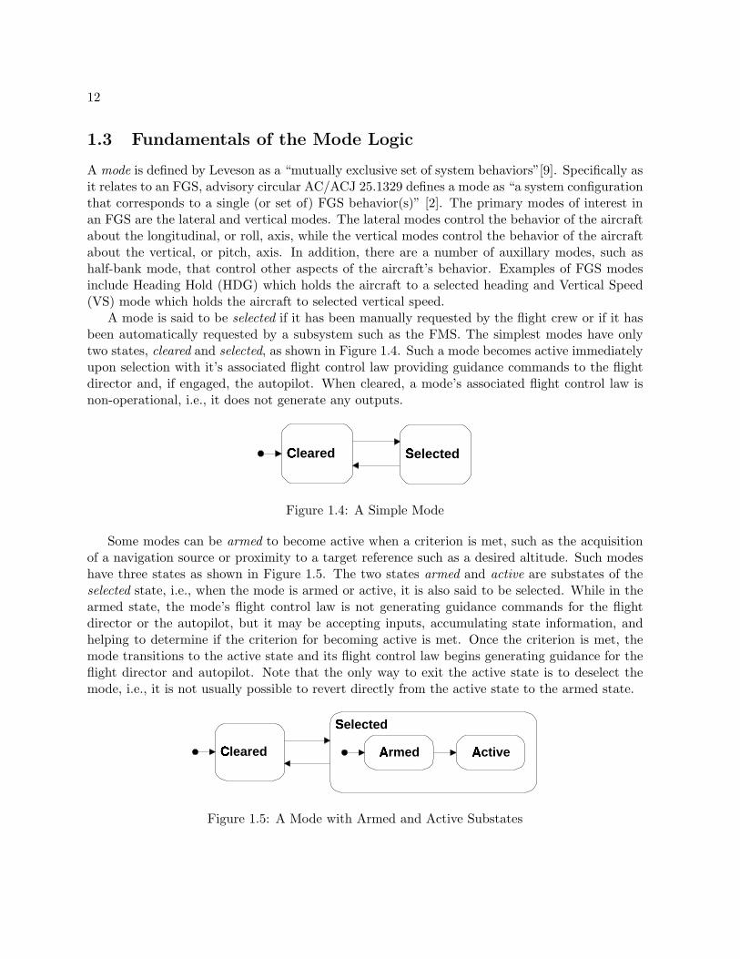
1.3 Fundamentals of the Mode Logic
A mode is defined by Leveson as a “mutually exclusive set of system behaviors”[9]. Specifically asit relates to an FGS, advisory circular AC/ACJ 25.1329 defines a mode as “a system configurationthat corresponds to a single (or set of) FGS behavior(s)” [2]. The primary modes of interest inan FGS are the lateral and vertical modes. The lateral modes control the behavior of the aircraftabout the longitudinal, or roll, axis, while the vertical modes control the behavior of the aircraftabout the vertical, or pitch, axis. In addition, there are a number of auxillary modes, such ashalf-bank mode, that control other aspects of the aircraft’s behavior. Examples of FGS modesinclude Heading Hold (HDG) which holds the aircraft to a selected heading and Vertical Speed(VS) mode which holds the aircraft to selected vertical speed.
A mode is said to be selected if it has been manually requested by the flight crew or if it hasbeen automatically requested by a subsystem such as the FMS. The simplest modes have onlytwo states, cleared and selected, as shown in Figure 1.4. Such a mode becomes active immediatelyupon selection with it’s associated flight control law providing guidance commands to the flightdirector and, if engaged, the autopilot. When cleared, a mode’s associated flight control law isnon-operational, i.e., it does not generate any outputs.
Cleared �
Selected �
Figure 1.4: A Simple Mode
Some modes can be armed to become active when a criterion is met, such as the acquisitionof a navigation source or proximity to a target reference such as a desired altitude. Such modeshave three states as shown in Figure 1.5. The two states armed and active are substates of theselected state, i.e., when the mode is armed or active, it is also said to be selected. While in thearmed state, the mode’s flight control law is not generating guidance commands for the flightdirector or the autopilot, but it may be accepting inputs, accumulating state information, andhelping to determine if the criterion for becoming active is met. Once the criterion is met, themode transitions to the active state and its flight control law begins generating guidance for theflight director and autopilot. Note that the only way to exit the active state is to deselect themode, i.e., it is not usually possible to revert directly from the active state to the armed state.
Selected �
Armed �
Cleared �
Active �
Figure 1.5: A Mode with Armed and Active Substates

13
Some modes also distinguish between capturing and tracking of the target reference or navi-gation source. Such a mode is shown in Figure 1.6. Once in the active state, such a mode’s flightcontrol law first captures the target by manuvering the aircraft to align it with the navigationsource or reference. Once correctly aligned, the mode transitions to the tracking state in which itholds the aircraft on the target. Both the capture and track states are substates of the active stateand the mode’s flight control law is active in both states, i.e., generating guidance commands forthe flight director and autopilot. Note that the only way to exit the active, track, or capturestates is to deselect the mode, i.e., it is not possible to revert directly from the track state to thecapture state or from the active state to the armed state.
Selected �
Active
Capture �
Track �Armed Cleared
�
Figure 1.6: A Mode with Capture and Track Substates
The mode logic consists of all the available modes and the rules for transitioning betweenthem. Figure 1.7 provides an overview of the modes described in this specification. Traditionally,aircraft modes are associated with a flight control law that determines the guidance providedto the flight director or autopilot. For example, in Figure 1.7, there are lateral modes of RollHold, Heading Hold, Navigation, Lateral Approach, and Lateral Go Around. These control theguidance about the longitudinal, or roll, axis. Guidance about the vertical, or pitch, axis iscontrolled by the vertical modes of Pitch, Vertical Speed, Altitude Hold, Altitude Select, VerticalApproach, and Vertical Go Around. Each of these are associated with one or more control laws.
Also shown in Figure 1.7 are several auxillary modes such as Pilot Flying, Independent Mode,FD, and AP, that describe the status of key state variables. While these have an important affectupon the behavior of the aircraft, they are not directly associated with specific flight controllaws, and are not usually viewed as “modes” by system designers in the same way the lateral andvertical modes are.
In order to provide effective guidance of the aircraft, these modes are tightly synchronized sothat only a small portion of their total state space is actually reachable. For example, to ensurethat meaningful guidance is provided to the flight director and autopilot, only one lateral andone vertical mode can be active at any time. For the same reason, if the autopilot is engaged orthe flight director is turned on, at least one lateral and one vertical mode must be active. Otherconstraints enforce sequencing of modes that are dictated by the characteristics of the aircraft andthe airspace. For example, vertical approach mode is not usually allowed to become active untillateral approach mode has become active to ensure that the aircraft is horizontally centered onthe localizer before tracking the glideslope. These constraints are clearly important to safe flight,and can become quite complex. The mode logic is responsible for enforcing all these constraints.

14
Flight Modes
On Vertical Modes
Vertical Approach
Selected �
Armed Cleared
�
Active
Altitude Select
Selected �
Active �
Capture �
Track �
Armed �Cleared
�
Vertical Go Around
Selected �
Cleared �
Altitude Hold
Selected �
Cleared �
Vertical Speed �
Selected �
Cleared �
Pitch
Selected �
Cleared �
Lateral Modes
Lateral Approach
Selected �
Armed Cleared
�
Active
Lateral Go Around
Selected �
Cleared �
Heading Hold
Selected �
Cleared �
Roll Hold
Selected �
Cleared �
Off Navigation
Selected �
Armed Cleared
�
Active
Pilot Flying
Right Left
Independent Mode
On �
Off �
FD
On �
Off �
AP
Disengaged Engaged
Figure 1.7: FGS Mode Logic

Chapter 2
The FGS Requirements Specification
A requirements specification must meet the needs of a diverse set of stakeholders, including but notlimited to the customer, end users, program management, systems engineers, software engineers,hardware engineers, test engineers, and regulatory agencies. It must be clear enough that endusers can understand it, yet complete and precise enough that the engineers can implement thesystem correctly and develop a comprehensive set of test cases. It must be robust in the face ofchange so that small changes only require small efforts. Ideally, the specification should supportthe development of a family of products, so that it can easily be reused to develop an entire lineof similar products.
The FGS requirements specification described in this document is organized to meet thesegoals. Its structure is hierarchial, allowing the reader to start with the entire subsystem, thenexamine individual components in greater detail. To enhance readability, it makes heavy useof the tabular formats developed in RSML−e to make the complex logic of the Traffic CollisionAvoidance System (TCAS) accessible to pilots, engineers, and regulatory authorities.[6]
Some of these goals, particularly those related to robustness in the face of change and supportfor product families, are best achieved by organizing the specification into pieces that are logicallyrelated and likely to change together and by defining interfaces between these components thatare unlikely to change. The current version of RSML−e does not directly support these notions,though extensions are planned for future versions that will.
However, this specification has been written as though these features were available. Functionsthat are logically related are grouped together into components, with details that are likely tochange encapsulated within these components. Rather than referring to these directly in the otherparts of the specification, interfaces (e.g., functions or macros) are defined that should remainstable over time for use in the rest of the specification. Many of the architectural decisionsare based on an extensive commonality analysis of several Flight Guidance Systems to determinewhich features change and which remain stable over a period of time. To facilitate such anticipatedchanges, the architecture implicitly defines a framework in which common patterns and interfacesare used across similar components.
15

16
Flight Guidance System
Flight Control Panel
Offside FGS
Air Data System
Flight Director
Independent Mode
Pilot Flying
Navigation Sources
Auto Pilot
References Flight
Control Laws
Flight Modes
Vertical Modes
PTCH VS �
ALT � ALT
�
SEL � APPR
�GA
�FLC
Lateral Modes
ROLL HDG NAV APPR �
GA �
Figure 2.1: Flight Guidance Specification Overview
2.1 Overview of the FGS Specification
The top level structure of the FGS is shown in Figure 2.1. The enclosing box labeled FlightGuidance System represents the full specification. The components located on the edge of theFlight Guidance System are boundary components that define the system’s view of its interfaceswith the outside world. These do not define the behavior of the actual external subsystem.Rather, they define the behavior of that subsystem that the FGS must be aware of. For example,the component labeled Flight Control Panel (FCP) only defines what information is received byand sent to the Flight Control Panel and does not define the full behavior of that actual device.
Each component may define new events or values that are used by other components. Forexample, the FCP mentioned above defines and exports events for each switch that can be pressedon the panel. In fact, since several of these events can occur at the same time, the FCP componentdefines a prioritization of these events so that only the highest priority events are seen by the restof the specification (see Section 2.2).
The heart of the specification is the definition of the mode logic contained in the Modes

17
component. This is further broken down into the Lateral Modes and Vertical Modes, which arein turn broken down into individual modes. The lateral and vertical modes all present standardinterfaces to their parent modules, making it staightforward to add, remove, or substitute modes,a common source of variation in a FGS. In addition, many of the modes share a common behaviorthat can be specified once, then tailored to define the behavior of each individual mode.
The following sections provide an overview of each individual component. Detailed specifica-tions of the components can be found in the remainder of this chapter.
Flight Control Panel (page 103) The Flight Control Panel (FCP) is the primary device withwhich the flight crew interacts with the FGS. This component defines the FGS’s view ofthe FCP. This consists of the definition of the monitored variables representing the switchesand dials of the FCP and the controlled variables representing the lamps displayed on theFCP. A few additional inputs, such as the SYNC and AP Disengage switches on the controlyokes and the GA switches on the throttles, are routed through the FCP aand are definedhere. This component also defines FCP specific events, such as the pressing of a switch,used in the rest of the specification. These events are prioritized so that if multiple eventsoccur at the same time, only the most significant events are seen by the other parts of thespecification.
Flight Director (page 25) The Flight Director (FD) displays the pitch and roll guidance com-mands to the pilot and copilot on the Primary Flight Display. This component defines whenthe Flight Director guidance cues are turned on and off.
Independent Mode (page 30) Normally, the FGS operates in dependent mode in which thepilot flying (PF) side of the FGS provides the mode annunciations and FD guidance com-mands to both PFDs. While in dependent mode, the pilot not flying (PNF) side of the FGSsynchronizes its modes to the pilot flying side. Under final approach conditions and duringtakeoff or go around modes, the FGS operates in independent mode in which each sideoperates independently of the other side and provides mode annunciations and FD guid-ance commands to its own PFD. This component defines when the FGS enters independentmode.
Pilot Flying (page 29) The transfer switch on the FCP is used to determine which FGS providesmode annunciations and guidance commands to the PFDs while in dependent mode. Thiscomponent defines which side is the Pilot Flying side. It also defines the notion of the“active” side of the FGS. A side of the FGS is said to be “active” if it is providing modeannunciations and guidance commands to its PFD.
Flight Control Laws (page 95) The Flight Control Laws generate the pitch and roll guidancecommands provided to the Flight Director and the Autopilot. Different Flight ControlLaws are armed or activated based on the current modes of the FGS. They also provideinputs to the mode logic that determine when transitions are made from the armed to theactive state. While the Flight Control Laws are not specified in this model, this componentdefines the interface between them and the mode logic and defines the events provided by

18
the Flight Control Laws that the mode logic depends upon. As with events provided by theFlight Control Panel, some of these are prioritized so that if multiple events occur at thesame time, only the most significant events are seen by the other parts of the specification.
Navigation Sources (page 127) The FGS receives navigation information from several sources,including VHF Omni-Directional Range (VOR) for lateral navigation, Localizer (LOC)for precision lateral approach, and Glideslope (GS) for precision vertical approach. Thiscomponent defines the FGS’s view of its navigation sources. This includes definition of thetypes of sources available, the currently selected source, and the information available fromthat source.
Air Data System (page 128) The Air Data System provides information about the aircraftstate sensed from the surrounding air mass such as pressure altitude and indicated airspeed.This component defines the FGS’s view of the Air Data System.
References (page 129)
References refer to target values used by several of the modes, such as the PreselectedAltitude. These may be set by the flight crew through the Flight Control Panel, or set tothe current aircraft value on entry to a mode or a synchronization request. The referencesmay be physically maintained by a variety of systems. This component defines the FGS’sview of the references. Details of how these values are obtained from other systems areencapsulated within this component.
Autopilot (page 130) The Autopilot (AP) commands the movement the control surfaces basedon the pitch and roll commands generated by the FGS. This component defines the FGS’sview of the AP.
Offside FGS (page 133) The FGS has two physical sides, or channels, on the left and rightsides of the aircraft. These provide redundant implementations that communicate witheach other over a cross-channel bus. This component defines this side of the FGS’s view ofthe other side.
Flight Modes (page 32) The flight modes determine which modes of operation of the FGSare active and armed at any given moment. These in term determine which flight controllaws are generating the commands directing the aircraft along the lateral (roll) and vertical(pitch) axes. This component encapsulates the definitions of the lateral and vertical modesand defines how they are synchronized.
Lateral Modes (page 35) The lateral modes select the control laws generating commands di-recting the aircraft along the lateral, or roll, axis. This component describes the specificlateral modes present in this aircraft and defines how they are synchronized.
Roll Hold (ROLL) Mode (page 37) In Roll Hold mode the FGS generates guidancecommands to hold the aircraft at a fixed bank angle. Roll Hold mode is the basic

19
lateral mode and is always active when the modes are displayed and no other lateralmode is active.
Heading Select (HDG) Mode (page 40) In Heading Select mode, the FGS providesguidance commands to to track the Selected Heading displayed on the PFD.
Lateral Navigation (NAV) Mode (page 40) In Lateral Navigation mode, the FGS pro-vides guidance commands to acquire and track lateral guidance for en route navigationand non-precision approaches. Lateral Navigation is an arming mode, i.e., after beingselected, it must remained armed for a period of time before it can become active.
Lateral Approach (LAPPR) Mode (page 50) In Lateral Approach mode, the FGS pro-vides guidance commands to acquire and track lateral guidance for precision and non-precision approaches. Lateral Approach is an arming mode, i.e., after being selected,it must remained armed for a period of time before it can become active.
Go Around (GA) Mode) (page 56) In Go Around mode the FGS generates guidancecommands for the pilot after aborting an approach. The AP is never engaged during GoAround mode. Lateral Go Around mode provides guidance to maintain the referenceheading.
Vertical Modes (page 60) The vertical modes select the control laws generating commandsdirecting the aircraft along the vertical, or pitch, axis. This component describes the specificvertical modes present in this aircraft and defines how they are synchronized.
Pitch Hold (PITCH) Mode (page 62) In Pitch Hold mode the FGS generates guidancecommands to hold the aircraft at a fixed pitch angle. Pitch Hold mode is the basicvertical mode and is always active when the modes are displayed and no other verticalmode is active.
Vertical Speed (VS) Mode (page 65) In Vertical Speed mode, the FGS provides pitchguidance commands to to hold the aircraft to the Vertical Speed (VS) reference.
Flight Level Change (FLC) Mode (page 69)In Flight Level Change mode, the FGS provides guidance commands to acquire andtrack an Indicated Airspeed (IAS) or Mach Reference Airspeed, taking into accountthe need to climb or descend to bring the aircraft to the PreSelector Altitude (PSA).
Altitude Hold (ALT) Mode (page 73)In Altitude Hold mode, the FGS provides pitch guidance commands to to acquire andtrack the Altitude reference, which is set to the current altitude when the mode isactivated or upon a synchronization request by the flight crew.
Altitude Select (ALTSEL) Mode (page 77)In Altitude Select mode, the FGS provides guidance commands to capture and trackthe Preselected Altitude. Altitude Select is an arming mode, i.e., after being selected, itmust remained armed for a period of time before it can become active. Altitude Selectmode is normally armed, although it is automically deselected by the activatation of

20
Vertical Approach, Go Around, or Altitude Hold mode. While in the armed state, theFGS monitors the aircraft closure rate towards the target altitude and determines theoptimum capture point to transition to the capture state. In the capture state, theFGS generates vertical guidance commands to perform a smooth capture of the targetaltitude. Once it acquires the target altitude, it enters the track state, during which itgenerates vertical guidance commands to maintain the aircraft at the target altitude.
Vertical Approach (VAPPR) Mode (page 85)In Vertical Approach mode, the FGS provides guidance commands to track verticalguidance for ILS precision Glideslope approaches. Vertical Approach is an armingmode, i.e., after being selected, it must remained armed for a period of time before itcan become active.
Vertical Go Around (VGA) Mode (page 91)In Go Around mode, the FGS provides guidance to the pilot after aborting an ap-proach. The AP is never engaged during Go Around mode. Vertical Go Around modeprovides guidance to maintain a fixed pitch angle.
2.2 Prioritization of Events
An issue that frequently arises in the specification of embedded systems is how to handle multipleevents that occur at the same point in time. Here, we assume that an event corresponds to aninstantaneous change in some input or state variable. One school argues that since an eventoccurs at a point in time, it is impossible for two events to occur at precisely the same moment,and simultaneous events should be prohibited in the underlying formal model. While theoreticallyappealing, many embedded systems are polling systems that periodically sample their inputs. Itis difficult to imagine how a polling system could be built that could guarantee that no morethan one input changes between any two samples. Even interrupt driven systems are ultimatelyimplemented as digital systems where interrupts are only handled at well defined boundaries,such as the end of an instruction, and multiple interrupts can be observed at these boundaries.
From a practical standpoint, it seems that the required abstraction is to allow one or moreevents to occur at the same time, and to deal with this within the specification. RSML−e makesthe one message assumption that at most one message can arrive at any given point in time.However, within a message, several fields can change value, allowing more than one input eventto occur at the same time. Since we did not know how the inputs to the mode logic would beimplemented in a specific system, we decided to group the inputs into large messages in order tomake as few assumptions as possible about the disjointness of input events.
In verifying the behavior of the mode logic, it became clear that the behavior of the systemwhen two or more events occurred at the same time would indeed have to be carefully consideredif the system was to have the correct behavior and satisfy even the most basic of safety properties(e.g., no more than one lateral mode or vertical mode active at the same time). Our approachwas to define a prioritization of the input events such that only the highest priority event is seenby the main body of the specification and the lower priority events are discarded. For example,
21
it seems reasonable to respond to the pilot pressing the Go Around switch and ignore the copilotpressing the Flight Director switch, rather than the other way around.
This approach is reasonable for most combinations of events. However, a few events, such asthe acquisition of a navigation beacon, do not need to be acted upon immediately, but shouldnot be simply discarded. These were given the lowest possible priority, and the condition oftheir being true, rather than the event of their becoming true, was used to trigger the associatedtransitions. In this way, processing of the event might be delayed, but would always be completedas soon as no higher priority event blocked it.
Other approaches are of course feasible. For example, one could queue the input events andprocess them in the order received. This introduces considerable complexity into the model, andthe simpler prioritization described here actually appears to be the more appropriate solution.One advantage of this approach is that it makes the solution explicit and easily reviewed.
We also attempted to localize this logic in the specification by introducing macros (predi-cates) of the form When Event Name Seen. These macros are true only when the underlyingevent occurs and no higher priority event has occurred at the same time. By using only theWhen Event Name Seen macros in the body of the specification, it is straightforward to changethe prioritization of events, or even to implement a more complicated approach such as thequeueing model discussed earlier.
As formal verification of the model proceeded, it became clear that it was possible to processsome combinations of events in parallel. As a result we changed the prioritization from a total toa partial order, as shown in Figure 2.2. In this diagram, an event has a higher priority than allevents that can be reached from it by following a downward chain of arrow and will supersede thoseevents. If no path exists between two events, then the two events can be processed concurrently.Thus, pressing the SYNC switch supersedes all events except pressing the AP Disconnect orAP Engage switch, which can be processed in parallel with it. In like manner, pressing theHDG switch will supersede pressing the NAV switch, the Pilot Flying Switch, the Flight Directorswitch, and any of the capture or track conditions. However, a press of the HDG switch can beprocessed in parallel with any of the switches associated only with vertical modes, such as theALT switch.
It is worth noting that this partial order could only have been verified with confidence throughthe use of formal analysis tools such as model checkers and theorem provers. A full descriptionof this verification activity will be provided in a later report.

22
SYNC Switch Pressed
GA Switch Pressed
ALTSEL Target Changed �
ALT Switch Pressed �
FLC Switch Pressed
VS Switch Pressed
VS Wheel Rotated
APPR Switch Pressed �
AP Disconnect Switch Pressed
AP Engage Switch Pressed
Transfer Switch Pressed
FD Switch Pressed
HDG Switch Pressed
NAV Switch Pressed
LAPPR Capture Condition Met
ALTSEL Capture Condition Met
ALTSEL Track Condition Met
VAPPR Capture Condition Met
NAV Capture Condition Met
Figure 2.2: The Partial Order of Event Priorities

23
2.3 Basic Definitions
This section defines types and constants that are used throughout the specification.
Type
Side
Possible Values: LEFT, RIGHT
Type
On Off
Possible Values: Off, On
Type
Base State
Possible Values: Cleared, Selected
Type
Selected State
Possible Values: Armed, Active
Type
Active State
Possible Values: Capture, Track

24
Constant
THIS SIDE
Units: N/A
Value: LEFTPurpose: This constant defines which side of the FGS (channel) is being specified. Thespecifications of both sides, left and right, are identical except for this constant.

25
2.4 Flight Director (FD)
The Flight Director (FD) displays the pitch and roll guidance commands to the pilot and copiloton the Primary Flight Display. This component defines when the Flight Director guidance cuesare turned on and off.
Definitions of Values to be Imported
Macro
When Turn FD On
Condition:
AND
OR
When FD Switch Pressed Seenm-103() T · · · · ·When(APv-132 =Engaged) · T · · · ·Overspeed Conditionm-128() · · T · · ·When Lateral Mode Manually Selectedm-26() · · · T · ·When Vertical Mode Manually Selectedm-27() · · · · T ·When Pilot Flying Transferm-29() · · · · · TPilot Flyingv-29 =THIS SIDELEFT · · · · · TPrevious Step(Mode Annunciations Onv-33) · · · · · T
Purpose: This event defines when the onside FD is to be turned on (i.e., displayed on thePFD).

26
Macro
When Turn FD Off
Condition:
AND
When FD Switch Pressed Seenm-103() TOverspeed Conditionm-128() F
Purpose: This event defines when the onside FD is to be turned off (i.e., removed from thePFD).
Macro
When Lateral Mode Manually Selected
Condition:
AND
OR
Previous Step(Mode Annunciations Onv-33) F F F F · · · ·Is This Side Activev-30 · · · · T T T TWhen HDG Switch Pressed Seenm-109() T · · · T · · ·When NAV Switch Pressed Seenm-108() · T · · · T · ·When APPR Switch Pressed Seenm-115() · · T · · · T ·When GA Switch Pressed Seenm-116() · · · T · · · T
Purpose: This event defines when a lateral mode is manually selected.

27
Macro
When Vertical Mode Manually Selected
Condition:
AND
OR
Previous Step(Mode Annunciations Onv-33) F F F F F · · · · · · ·Is This Side Activev-30 · · · · · T T T T T T TWhen VS Switch Pressed Seenm-111() T · · · · T · · · · · ·When FLC Switch Pressed Seenm-112() · T · · · · T · · · · ·When ALT Switch Pressed Seenm-113() · · T · · · · T · · · ·When APPR Switch Pressed Seenm-115() · · · T · · · · T · · ·When GA Switch Pressed Seenm-116() · · · · T · · · · T · ·When VS Pitch Wheel Rotated Seenm-110() · · · · · · · · · · T ·Previous Step(Is VS Activev-66) · · · · · · · · · · F ·Previous Step(Is VAPPR Activev-87) · · · · · · · · · · F ·Previous Step(Overspeediv-128) · · · · · · · · · · F ·When ALTSEL Target Altitude Changed Seenm-114() · · · · · · · · · · · TPrevious Step(Is ALTSEL Activev-80) · · · · · · · · · · · T
Purpose: This event defines when a vertical mode is manually selected.

28
Definitions of Values to be Exported
State Variable
Onside FD On
Parent: None
Type: BooleanInitial Value: FalseClassified as: CONTROLLED:= Onside FDv-28 =On if True
Purpose: Indicates if the FD Guidance cues should be displayed on the PFD.
Definitions of Values to be Encapsulated
State Variable
Onside FD
Parent: None
Type: {Off, On}ty-23
Initial Value: OffClassified as: StateOff −→ On if When Turn FD Onm-25()
On −→ Off if When Turn FD Offm-26()
Purpose: This variable maintains the current state of the onside Flight Director.

29
2.5 Pilot Flying (PF)
The transfer switch on the FCP is used to determine which FGS provides mode annunciationsand guidance commands to the PFDs while in dependent mode. This component defines whichside is the Pilot Flying side. It also defines the notion of the “active” side of the FGS. A side ofthe FGS is said to be “active” if it is providing mode annunciations and guidance commands toits PFD.
Definitions of Values to be Exported
State Variable
Pilot Flying
Parent: None
Type: {LEFT, RIGHT}ty-23
Initial Value: LEFTClassified as: StateLEFT −→ RIGHT if When Transfer Switch Pressed Seenm-104()
RIGHT −→ LEFT if When Transfer Switch Pressed Seenm-104()
Purpose: This state variable maintains which side this side of the FGS believes isthe Pilot Flying side.
Macro
When Pilot Flying Transfer
Condition: Changed(Pilot Flyingv-29)
Purpose: This event occurs when the pilot flying side changes to the other side.
30
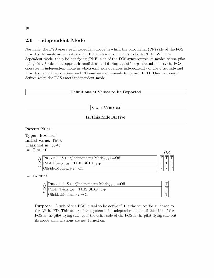
2.6 Independent Mode
Normally, the FGS operates in dependent mode in which the pilot flying (PF) side of the FGSprovides the mode annunciations and FD guidance commands to both PFDs. While independent mode, the pilot not flying (PNF) side of the FGS synchronizes its modes to the pilotflying side. Under final approach conditions and during takeoff or go around modes, the FGSoperates in independent mode in which each side operates independently of the other side andprovides mode annunciations and FD guidance commands to its own PFD. This componentdefines when the FGS enters independent mode.
Definitions of Values to be Exported
State Variable
Is This Side Active
Parent: None
Type: BooleanInitial Value: TrueClassified as: State:= True if
AND
OR
Previous Step(Independent Modev-31) =Off F T TPilot Flyingv-29 =THIS SIDELEFT · T FOffside Modesv-135 =On · · F
:= False if
AND
Previous Step(Independent Modev-31) =Off TPilot Flyingv-29 =THIS SIDELEFT FOffside Modesv-135 =On T
Purpose: A side of the FGS is said to be active if it is the source for guidance tothe AP its FD. This occurs if the system is in independent mode, if this side of theFGS is the pilot flying side, or if the other side of the FGS is the pilot flying side butits mode annunciations are not turned on.
31
Definitions of Values to be Encapsulated
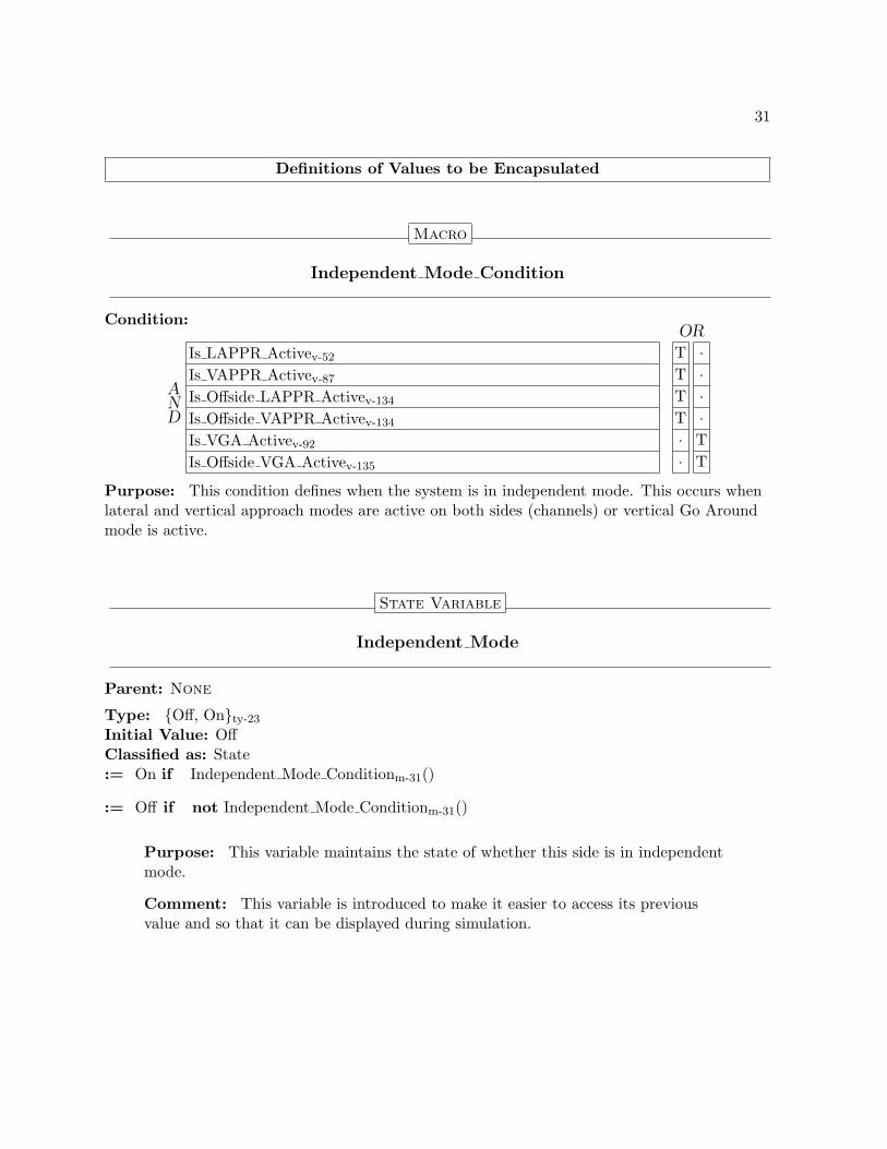
Macro
Independent Mode Condition
Condition:
AND
OR
Is LAPPR Activev-52 T ·Is VAPPR Activev-87 T ·Is Offside LAPPR Activev-134 T ·Is Offside VAPPR Activev-134 T ·Is VGA Activev-92 · TIs Offside VGA Activev-135 · T
Purpose: This condition defines when the system is in independent mode. This occurs whenlateral and vertical approach modes are active on both sides (channels) or vertical Go Aroundmode is active.
State Variable
Independent Mode
Parent: None
Type: {Off, On}ty-23
Initial Value: OffClassified as: State:= On if Independent Mode Conditionm-31()
:= Off if not Independent Mode Conditionm-31()
Purpose: This variable maintains the state of whether this side is in independentmode.
Comment: This variable is introduced to make it easier to access its previousvalue and so that it can be displayed during simulation.
32
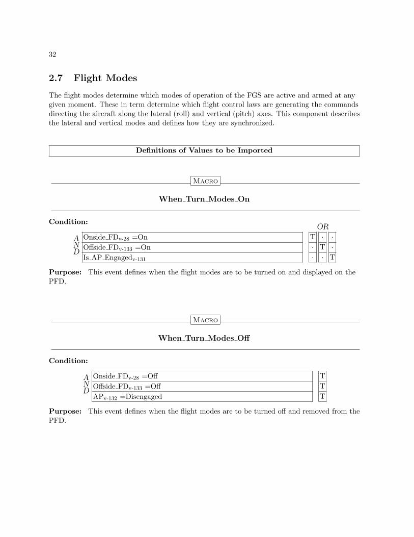
2.7 Flight Modes
The flight modes determine which modes of operation of the FGS are active and armed at anygiven moment. These in term determine which flight control laws are generating the commandsdirecting the aircraft along the lateral (roll) and vertical (pitch) axes. This component describesthe lateral and vertical modes and defines how they are synchronized.
Definitions of Values to be Imported
Macro
When Turn Modes On
Condition:
AND
OR
Onside FDv-28 =On T · ·Offside FDv-133 =On · T ·Is AP Engagedv-131 · · T
Purpose: This event defines when the flight modes are to be turned on and displayed on thePFD.
Macro
When Turn Modes Off
Condition:
AND
Onside FDv-28 =Off TOffside FDv-133 =Off TAPv-132 =Disengaged T
Purpose: This event defines when the flight modes are to be turned off and removed from thePFD.

33
Definitions of Values to be Exported
State Variable
Mode Annunciations On
Parent: None
Type: BooleanInitial Value: FalseClassified as: CONTROLLED:= Modesv-34 =On if True
Purpose: Indicates if the mode annunications should be displayed on the PFD.

34
Definitions of Values to be Encapsulated
State Variable
Modes
Parent: None
Type: {Off, On}ty-23
Initial Value: OffClassified as: State:= Offside Modesv-135 if not Is This Side Activev-30
Off −→ On if
AND
Is This Side Activev-30 TWhen Turn Modes Onm-32() T
On −→ Off if
AND
Is This Side Activev-30 TWhen Turn Modes Offm-32() T
Purpose: This variable maintains the current state of whether the modeannunciations are turned on or off.
35
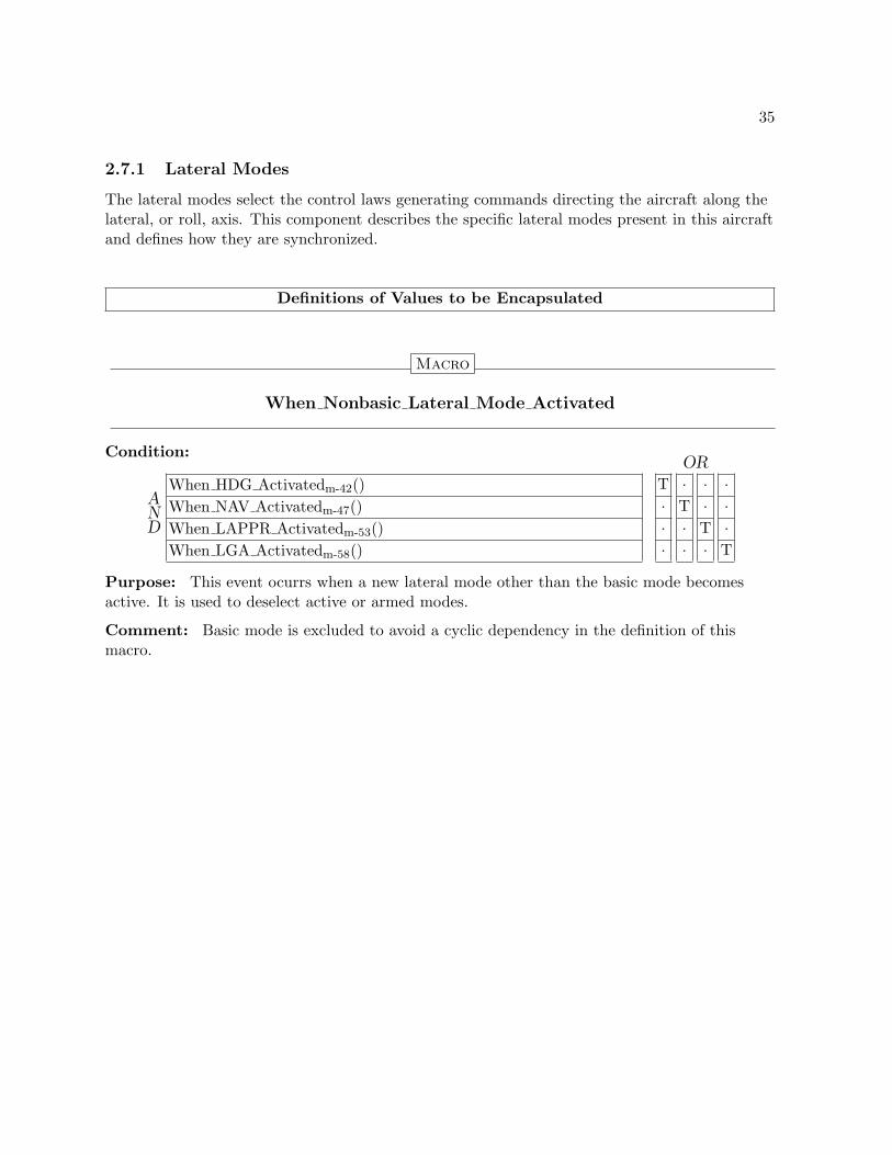
2.7.1 Lateral Modes
The lateral modes select the control laws generating commands directing the aircraft along thelateral, or roll, axis. This component describes the specific lateral modes present in this aircraftand defines how they are synchronized.
Definitions of Values to be Encapsulated
Macro
When Nonbasic Lateral Mode Activated
Condition:
AND
OR
When HDG Activatedm-42() T · · ·When NAV Activatedm-47() · T · ·When LAPPR Activatedm-53() · · T ·When LGA Activatedm-58() · · · T
Purpose: This event ocurrs when a new lateral mode other than the basic mode becomesactive. It is used to deselect active or armed modes.
Comment: Basic mode is excluded to avoid a cyclic dependency in the definition of thismacro.

36
Macro
Is No Nonbasic Lateral Mode Active
Condition:
AND
Is HDG Activev-41 FIs NAV Activev-46 FIs LAPPR Activev-52 FIs LGA Activev-57 F
Purpose: This condition indicates if no lateral mode except basic mode is active. It is used totrigger the activation of the basic lateral mode.
Comment: Basic mode is excluded to avoid a cyclic dependency in the definition of thismacro.

37
2.7.1.1 Roll Hold (ROLL) Mode
In Roll Hold mode the FGS generates guidance commands to hold the aircraft at a fixed bankangle. Roll Hold mode is the basic lateral mode and is always active when the modes aredisplayed and no other lateral mode is active.
Definitions of Values to be Imported
Macro
Select ROLL
Condition:
AND
Is No Nonbasic Lateral Mode Activem-36() TModesv-34 =On T
Purpose: This event defines when Roll Hold mode is to be selected. Roll Hold mode is thebasic, or default, mode and is selected whenever the mode annunciations are on and no otherlateral mode is active.
Comment: To avoid cyclic dependencies, the only way to select Roll Hold mode is to deselectthe active lateral mode, which will automatically activate Roll Hold.
Macro
Deselect ROLL
Condition:
AND
OR
When Nonbasic Lateral Mode Activatedm-35() T ·When(Modesv-34 =Off) · T
Purpose: The event defines when Roll Hold mode is to be deselected. This occurs when anew lateral mode is activated or the modes are turned off.

38
Definitions of Values to be Exported
State Variable
Is ROLL Selected
Parent: None
Type: BooleanInitial Value: FalseClassified as: CONTROLLED:= (ROLLv-39 =Selected) if True
Purpose: Indicates if ROLL mode is selected.
State Variable
Is ROLL Active
Parent: None
Type: BooleanInitial Value: FalseClassified as: CONTROLLED:= (ROLLv-39 =Selected) if True
Purpose: Indicates if ROLL mode is selected.
Comment: Even though ROLL Selected and ROLL Active are the same value,this is defined to provide a common set of controlled variables across all modes.

39
Definitions of Values to be Encapsulated
State Variable
ROLL
Parent: Modesv-34.On
Type: {Cleared, Selected}ty-23
Initial Value: UndefinedClassified as: State:= Offside ROLLv-136 if not Is This Side Activev-30
Undefined −→ Cleared if
AND
Select ROLLm-37() FIs This Side Activev-30 T
Undefined −→ Selected if
AND
Select ROLLm-37() TIs This Side Activev-30 T
Cleared −→ Selected if
AND
Select ROLLm-37() TIs This Side Activev-30 T
Selected −→ Cleared if
AND
Deselect ROLLm-37() TIs This Side Activev-30 T
Purpose: This variable maintains the current base state of Roll Hold mode, i.e.,whether it is cleared or selected. Note that if this side of the FGS is not active, itobtains its value from the off side. The normal transitions occur only when this sideis active.

40
2.7.1.2 Heading Select (HDG) Mode
In Heading Select mode, the FGS provides guidance commands to to track the Selected Headingdisplayed on the PFD.
Definitions of Values to be Imported
Macro
Select HDG
Condition: When HDG Switch Pressed Seenm-109()
Purpose: This event defines when Heading Select mode is to be selected.
Macro
Deselect HDG
Condition:
AND
OR
When HDG Switch Pressed Seenm-109() T · · ·When Nonbasic Lateral Mode Activatedm-35() · T · ·When Pilot Flying Transferm-29() · · T ·When(Modesv-34 =Off) · · · T
Purpose: This event defines when Heading Select mode is to be deselected.

41
Definitions of Values to be Exported
State Variable
Is HDG Selected
Parent: None
Type: BooleanInitial Value: FalseClassified as: CONTROLLED:= (HDGv-43 =Selected) if True
Purpose: Indicates if HDG mode is selected.
State Variable
Is HDG Active
Parent: None
Type: BooleanInitial Value: FalseClassified as: CONTROLLED:= (HDGv-43 =Selected) if True
Purpose: Indicates if HDG mode is active.
Comment: Even though HDG Selected and HDG Active are the same value, thisis defined to provide a common set of controlled variables across all modes.
42
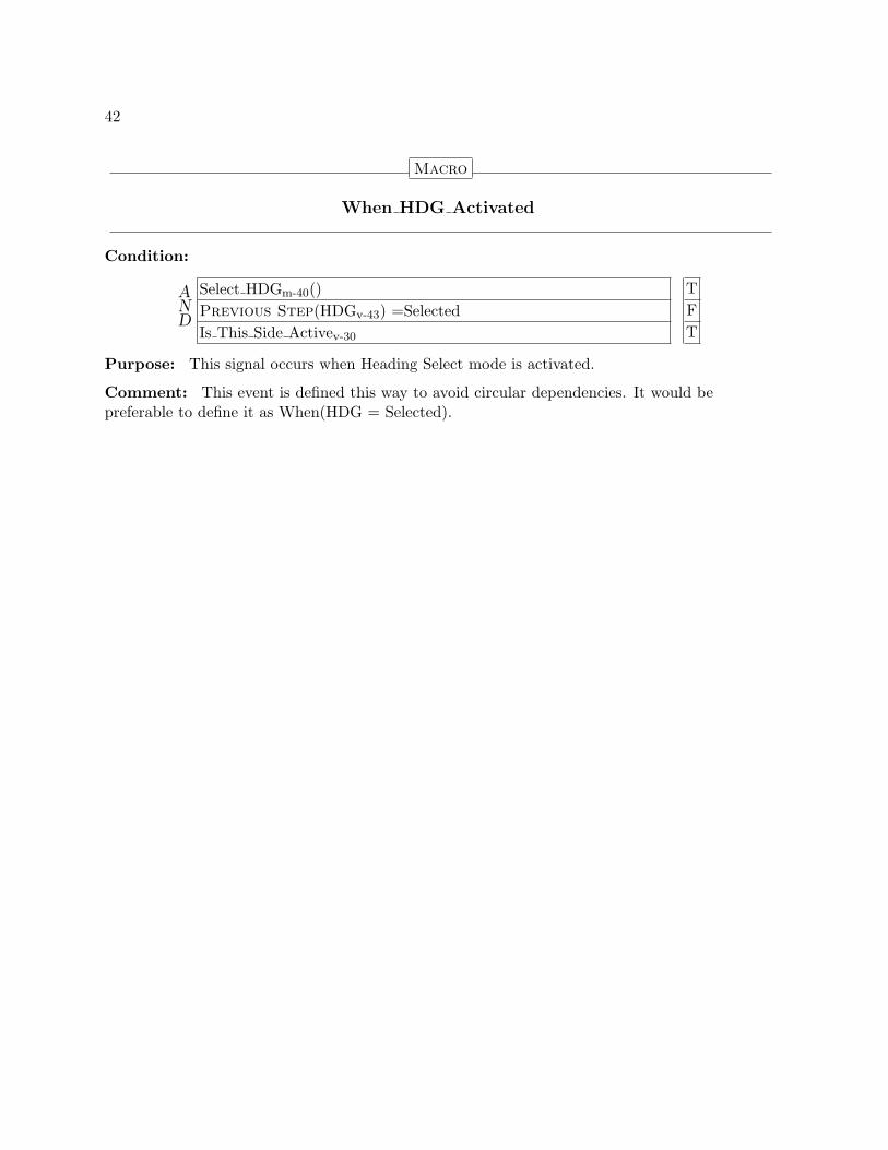
Macro
When HDG Activated
Condition:
AND
Select HDGm-40() TPrevious Step(HDGv-43) =Selected FIs This Side Activev-30 T
Purpose: This signal occurs when Heading Select mode is activated.
Comment: This event is defined this way to avoid circular dependencies. It would bepreferable to define it as When(HDG = Selected).

43
Definitions of Values to be Encapsulated
State Variable
HDG
Parent: Modesv-34.On
Type: {Cleared, Selected}ty-23
Initial Value: UndefinedClassified as: StatePurpose: This variable maintains the current base state of Heading Select mode, i.e., whetherit is cleared or selected. Note that if this side of the FGS is not active, it obtains its value fromthe off side. The normal transitions occur only when this side is active.
:= Offside HDGv-136 if not Is This Side Activev-30
Undefined −→ Cleared if
AND
Select HDGm-40() FIs This Side Activev-30 T
Undefined −→ Selected if
AND
Select HDGm-40() TIs This Side Activev-30 T
Cleared −→ Selected if
AND
Select HDGm-40() TIs This Side Activev-30 T
Selected −→ Cleared if
AND
Deselect HDGm-40() TIs This Side Activev-30 T

44
2.7.1.3 Navigation (NAV) Mode
In Lateral Navigation mode, the FGS provides guidance commands to acquire and track lateralguidance for en route navigation and non-precision approaches. Lateral Navigation is an armingmode, i.e., after being selected, it must remained armed for a period of time before it canbecome active.
Definitions of Values to be Imported
Macro
Select NAV
Condition: When NAV Switch Pressed Seenm-108()
Purpose: This event defines when Lateral Navigation mode is to be selected, i.e., to becomearmed.
Macro
Activate NAV
Condition: When NAV Track Cond Met Seenm-95()
Purpose: This event defines when Lateral Navigation mode is to transition from the armed tothe active state.

45
Macro
Deselect NAV
Condition:
AND
OR
When NAV Switch Pressed Seenm-108() T · · · ·When Selected Nav Source Changedv-127 · T · · ·When Selected Nav Frequency Changedv-127 · · T · ·When Pilot Flying Transferm-29() · · · T ·When(Modesv-34 =Off) · · · · T
Purpose: This event defines when Lateral Navigation mode is to be deselected, i.e., to becleared regardless of whether it is armed or active.
Macro
Dearm NAV
Condition: When LAPPR Armedm-53()
Purpose: This event defines when Lateral Navigation mode is to be cleared if it is armed, butto remain active if it is active.
Macro
Deactivate NAV
Condition: When Nonbasic Lateral Mode Activatedm-35()
Purpose: This event defines when Lateral Navigation mode is to be cleared if it is active, butto remain armed if it is armed.

46
Definitions of Values to be Exported
State Variable
Is NAV Selected
Parent: None
Type: BooleanInitial Value: FalseClassified as: CONTROLLED:= (NAVv-48 =Selected) if True
Purpose: Indicates if NAV mode is selected.
State Variable
Is NAV Active
Parent: None
Type: BooleanInitial Value: FalseClassified as: CONTROLLED:= (NAV Selectedv-49 =Active) if True
Purpose: Indicates if NAV mode is active.
47
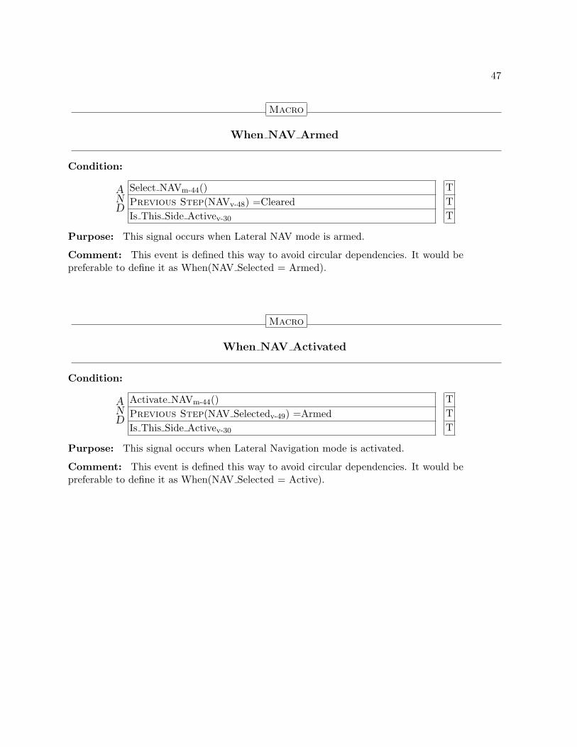
Macro
When NAV Armed
Condition:
AND
Select NAVm-44() TPrevious Step(NAVv-48) =Cleared TIs This Side Activev-30 T
Purpose: This signal occurs when Lateral NAV mode is armed.
Comment: This event is defined this way to avoid circular dependencies. It would bepreferable to define it as When(NAV Selected = Armed).
Macro
When NAV Activated
Condition:
AND
Activate NAVm-44() TPrevious Step(NAV Selectedv-49) =Armed TIs This Side Activev-30 T
Purpose: This signal occurs when Lateral Navigation mode is activated.
Comment: This event is defined this way to avoid circular dependencies. It would bepreferable to define it as When(NAV Selected = Active).

48
Definitions of Values to be Encapsulated
State Variable
NAV
Parent: Modesv-34.On
Type: {Cleared, Selected}ty-23
Initial Value: UndefinedClassified as: State:= Offside NAVv-137 if not Is This Side Activev-30
Undefined −→ Cleared if
AND
Select NAVm-44() FIs This Side Activev-30 T
Undefined −→ Selected if
AND
Select NAVm-44() TIs This Side Activev-30 T
Cleared −→ Selected if
AND
Select NAVm-44() TIs This Side Activev-30 T
Selected −→ Cleared if
AND
OR
Deselect NAVm-45() T · ·Dearm NAVm-45() · T ·Previous Step(NAV Selectedv-49) =Armed · T ·Deactivate NAVm-45() · · TPrevious Step(NAV Selectedv-49) =Active · · TIs This Side Activev-30 T T T
Purpose: This variable maintains the current base state of Lateral Navigationmode, i.e., whether it is cleared or selected. Note that if this side of the FGS is notactive, it obtains its value from the off side. The normal transitions occur only whenthis side is active.

49
State Variable
NAV Selected
Parent: Modesv-34.On . NAVv-48.Selected
Type: {Armed, Active}ty-23
Initial Value: UndefinedClassified as: State:= Offside NAV Selectedv-137 if not Is This Side Activev-30
Undefined −→ Armed if True
Armed −→ Active if
AND
Activate NAVm-44() TIs This Side Activev-30 T
Purpose: This variable maintains the current state of Lateral Navigation modewhen it is selected, i.e., whether it is armed or active. Note that if this side of theFGS is not active, it obtains its value from the off side. The normal transitionsoccur only when this side is active.

50
2.7.1.4 Lateral Approach (LAPPR) Mode
In Lateral Approach mode, the FGS provides guidance commands to acquire and track lateralguidance for precision and non-precision approaches. Lateral Approach is an arming mode, i.e.,after being selected, it must remained armed for a period of time before it can become active.
Definitions of Values to be Imported
Macro
Select LAPPR
Condition: When APPR Switch Pressed Seenm-115()
Purpose: This event defines when Lateral Approach mode is to be selected, i.e., to becomearmed.
Macro
Activate LAPPR
Condition: When LAPPR Track Cond Met Seenm-98()
Purpose: This event defines when Lateral Approach mode is to transition from the armed tothe active state.

51
Macro
Deselect LAPPR
Condition:
AND
OR
When APPR Switch Pressed Seenm-115() T · · · ·When Selected Nav Source Changedv-127 · T · · ·When Selected Nav Frequency Changedv-127 · · T · ·When Pilot Flying Transferm-29() · · · T ·When(Modesv-34 =Off) · · · · T
Purpose: This event defines when Lateral Approach mode is to be deselected, i.e., to becleared regardless of whether it is armed or active.
Macro
Dearm LAPPR
Condition: When NAV Armedm-47()
Purpose: This event defines when Lateral Approach mode is to be cleared if it is armed, butto remain active if it is active.
Macro
Deactivate LAPPR
Condition: When Nonbasic Lateral Mode Activatedm-35()
Purpose: This event defines when Lateral Approach mode is to be cleared if it is active, butto remain armed if it is armed.

52
Definitions of Values to be Exported
State Variable
Is LAPPR Selected
Parent: None
Type: BooleanInitial Value: FalseClassified as: CONTROLLED:= (LAPPRv-54 =Selected) if True
Purpose: Indicates if LAPPR mode is selected.
State Variable
Is LAPPR Active
Parent: None
Type: BooleanInitial Value: FalseClassified as: CONTROLLED:= (LAPPR Selectedv-55 =Active) if True
Purpose: Indicates if LAPPR mode is active.

53
Macro
When LAPPR Armed
Condition:
AND
Select LAPPRm-50() TPrevious Step(LAPPRv-54) =Cleared TIs This Side Activev-30 T
Purpose: This signal occurs when Lateral Approach mode is armed.
Comment: This event is defined this way to avoid circular dependencies. It would bepreferable to define it as When(LAPPR Selected = Armed).
Macro
When LAPPR Activated
Condition:
AND
Activate LAPPRm-50() TPrevious Step(LAPPR Selectedv-55) =Armed TIs This Side Activev-30 T
Purpose: This signal occurs when Lateral Approach mode is activated.
Comment: This event is defined this way to avoid circular dependencies. It would bepreferable to define it as When(LAPPR Selected = Active).

54
Definitions of Values to be Encapsulated
State Variable
LAPPR
Parent: Modesv-34.On
Type: {Cleared, Selected}ty-23
Initial Value: UndefinedClassified as: State:= Offside LAPPRv-138 if not Is This Side Activev-30
Undefined −→ Cleared if
AND
Select LAPPRm-50() FIs This Side Activev-30 T
Undefined −→ Selected if
AND
Select LAPPRm-50() TIs This Side Activev-30 T
Cleared −→ Selected if
AND
Select LAPPRm-50() TIs This Side Activev-30 T
Selected −→ Cleared if
AND
OR
Deselect LAPPRm-51() T · ·Dearm LAPPRm-51() · T ·Previous Step(LAPPR Selectedv-55) =Armed · T ·Deactivate LAPPRm-51() · · TPrevious Step(LAPPR Selectedv-55) =Active · · TIs This Side Activev-30 T T T
Purpose: This variable maintains the current base state of Lateral Approachmode, i.e., whether it is cleared or selected. Note that if this side of the FGS is notactive, it obtains its value from the off side. The normal transitions occur only whenthis side is active.

55
State Variable
LAPPR Selected
Parent: Modesv-34.On . LAPPRv-54.Selected
Type: {Armed, Active}ty-23
Initial Value: UndefinedClassified as: State:= Offside LAPPR Selectedv-138 if not Is This Side Activev-30
Undefined −→ Armed if True
Armed −→ Active if
AND
Activate LAPPRm-50() TIs This Side Activev-30 T
Purpose: This variable maintains the current state of Lateral Approach modewhen it is selected, i.e., whether it is armed or active. Note that if this side of theFGS is not active, it obtains its value from the off side. The normal transitionsoccur only when this side is active.

56
2.7.1.5 Lateral Go Around (LGA) Mode
In Go Around mode the FGS generates guidance commands for the pilot after aborting anapproach. The AP is never engaged during Go Around mode. Lateral Go Around modeprovides guidance to maintain the reference heading.
Definitions of Values to be Imported
Macro
Select LGA
Condition:
AND
When GA Switch Pressed Seenm-116() TOverspeed Conditionm-128() F
Purpose: This event defines when Lateral Go Around mode is to be selected.
Macro
Deselect LGA
Condition:
AND
OR
When(APv-132 =Engaged) T · · · · ·When Nonbasic Lateral Mode Activatedm-35() · T · · · ·When Nonbasic Vertical Mode Activatedm-60() · · T · · ·When SYNC Switch Pressed Seenm-117() · · · T · ·When Pilot Flying Transferm-29() · · · · T ·When(Modesv-34 =Off) · · · · · T
Purpose: This event defines when Lateral Go Around mode is to be deselected.

57
Definitions of Values to be Exported
State Variable
Is LGA Selected
Parent: None
Type: BooleanInitial Value: FalseClassified as: CONTROLLED:= (LGAv-59 =Selected) if True
Purpose: Indicates if LGA mode is selected.
State Variable
Is LGA Active
Parent: None
Type: BooleanInitial Value: FalseClassified as: CONTROLLED:= (LGAv-59 =Selected) if True
Purpose: Indicates if LGA mode is active.
Comment: Even though LGA Selected and LGA Active are the same value, thisis defined to provide a common set of controlled variables across all modes.

58
Macro
When LGA Activated
Condition:
AND
Select LGAm-56() TPrevious Step(LGAv-59) =Selected FIs This Side Activev-30 T
Purpose: This signal occurs when Lateral Go Around mode is activated.
Comment: This event is defined this way to avoid circular dependencies. It would bepreferable to define it as When(LGA = Selected).

59
Definitions of Values to be Encapsulated
State Variable
LGA
Parent: Modesv-34.On
Type: {Cleared, Selected}ty-23
Initial Value: UndefinedClassified as: State:= Offside LGAv-139 if not Is This Side Activev-30
Undefined −→ Cleared if
AND
Select LGAm-56() FIs This Side Activev-30 T
Undefined −→ Selected if
AND
Select LGAm-56() TIs This Side Activev-30 T
Cleared −→ Selected if
AND
Select LGAm-56() TIs This Side Activev-30 T
Selected −→ Cleared if
AND
Deselect LGAm-56() TIs This Side Activev-30 T
Purpose: This variable maintains the current state of Lateral Go Around mode.Note that if this side is not active, it obtains its value from the off side. The normaltransitions for Lateral Go Around mode occur only when this side is active.

60
2.7.2 Vertical Modes
The vertical modes select the control laws generating commands directing the aircraft along thevertical, or pitch, axis. This component describes the specific vertical modes present in thisaircraft and defines how they are synchronized.
Definitions of Values to be Encapsulated
Macro
When Nonbasic Vertical Mode Activated
Condition:
AND
OR
When VS Activatedm-67() T · · · · ·When FLC Activatedm-71() · T · · · ·When ALT Activatedm-75() · · T · · ·When ALTSEL Activatedm-81() · · · T · ·When VAPPR Activatedm-88() · · · · T ·When VGA Activatedm-93() · · · · · T
Purpose: This event indicates when a new vertical mode other than the basic mode becomesactive. It is used to deselect active or armed modes.
Comment: Basic mode is excluded to avoid a cyclic dependency in the definition of thismacro.

61
Macro
Is No Nonbasic Vertical Mode Active
Condition:
AND
Is VS Activev-66 FIs FLC Activev-71 FIs ALT Activev-74 FIs ALTSEL Activev-80 FIs VAPPR Activev-87 FIs VGA Activev-92 F
Purpose: This condition indicates if no vertical mode except basic mode is active. It is usedto trigger the activation of the basic lateral mode.
Comment: Basic mode is excluded to avoid a cyclic dependency in the definition of thismacro.

62
2.7.2.1 Pitch Hold (PITCH) Mode
In Pitch Hold mode the FGS generates guidance commands to hold the aircraft at a fixed pitchangle. Pitch Hold mode is the basic vertical mode and is always active when the modes aredisplayed and no other vertical mode is active.
Definitions of Values to be Imported
Macro
Select PITCH
Condition:
AND
Is No Nonbasic Vertical Mode Activem-61() TModesv-34 =On T
Purpose: Pitch Hold mode is the basic, or default, mode and is selected whenever the modeannunciations are on and no other vertical mode is active.
Comment: To avoid cyclic dependencies, the only way to select Pitch Hold mode is todeselect the active vertical mode, which will automatically activate Pitch Hold mode.
Macro
Deselect PITCH
Condition:
AND
OR
When Nonbasic Vertical Mode Activatedm-60() T ·When(Modesv-34 =Off) · T
Purpose: Pitch Hold mode is deselected when: a new vertical mode is activated or the modesare turned off.

63
Definitions of Values to be Exported
State Variable
Is PITCH Selected
Parent: None
Type: BooleanInitial Value: FalseClassified as: CONTROLLED:= (PITCHv-64 =Selected) if True
Purpose: Indicates if PITCH mode is selected.
State Variable
Is PITCH Active
Parent: None
Type: BooleanInitial Value: FalseClassified as: CONTROLLED:= (PITCHv-64 =Selected) if True
Purpose: Indicates if PITCH mode is active.
Comment: Even though PITCH Selected and PITCH Active are the same value,this is defined to provide a common set of controlled variables across all modes.

64
Definitions of Values to be Encapsulated
State Variable
PITCH
Parent: Modesv-34.On
Type: {Cleared, Selected}ty-23
Initial Value: UndefinedClassified as: State:= Offside PITCHv-139 if not Is This Side Activev-30
Undefined −→ Cleared if
AND
Select PITCHm-62() FIs This Side Activev-30 T
Undefined −→ Selected if
AND
Select PITCHm-62() TIs This Side Activev-30 T
Cleared −→ Selected if
AND
Select PITCHm-62() TIs This Side Activev-30 T
Selected −→ Cleared if
AND
Deselect PITCHm-62() TIs This Side Activev-30 T
Purpose: This variable maintains the current base state of Pitch Hold mode, i.e.,whether it is cleared or selected. Note that if this side of the FGS is not active, itobtains its value from the off side. The normal transitions occur only when this sideis active.

65
2.7.2.2 Vertical Speed (VS) Mode
In Vertical Speed mode, the FGS provides pitch guidance commands to to hold the aircraft tothe Vertical Speed (VS) reference.
Definitions of Values to be Imported
Macro
Select VS
Condition:
AND
When VS Switch Pressed Seenm-111() TOverspeed Conditionm-128() FPrevious Step(Is VAPPR Activev-87) F
Purpose: This event defines when Vertical Speed mode is to be selected.
Macro
Deselect VS
Condition:
AND
OR
When VS Switch Pressed Seenm-111() T · · ·When Nonbasic Vertical Mode Activatedm-60() · T · ·When Pilot Flying Transferm-29() · · T ·When(Modesv-34 =Off) · · · T
Purpose: This event defines when Vertical Speed mode is to be deselected.

66
Definitions of Values to be Exported
State Variable
Is VS Selected
Parent: None
Type: BooleanInitial Value: FalseClassified as: CONTROLLED:= (VSv-68 =Selected) if True
Purpose: Indicates if VS mode is selected.
State Variable
Is VS Active
Parent: None
Type: BooleanInitial Value: FalseClassified as: CONTROLLED:= (VSv-68 =Selected) if True
Purpose: Indicates if VS mode is active.
Comment: Even though VS Selected and VS Active are the same value, this isdefined to provide a common set of controlled variables across all modes.

67
Macro
When VS Activated
Condition:
AND
Select VSm-65() TPrevious Step(VSv-68) =Selected FIs This Side Activev-30 T
Purpose: This signal occurs when Vertical Speed mode is activated.
Comment: This event is defined this way to avoid circular dependencies. It would bepreferable to define it as When(VS = Selected).

68
Definitions of Values to be Encapsulated
State Variable
VS
Parent: Modesv-34.On
Type: {Cleared, Selected}ty-23
Initial Value: UndefinedClassified as: State:= Offside VSv-140 if not Is This Side Activev-30
Undefined −→ Cleared if
AND
Select VSm-65() FIs This Side Activev-30 T
Undefined −→ Selected if
AND
Select VSm-65() TIs This Side Activev-30 T
Cleared −→ Selected if
AND
Select VSm-65() TIs This Side Activev-30 T
Selected −→ Cleared if
AND
Deselect VSm-65() TIs This Side Activev-30 T
Purpose: This variable maintains the current base state of Vertical Speed mode,i.e., whether it is cleared or selected. Note that if this side of the FGS is not active,it obtains its value from the off side. The normal transitions occur only when thisside is active.

69
2.7.2.3 Flight Level Change (FLC) Mode
In Flight Level Change mode, the FGS provides guidance commands to acquire and track anIndicated Airspeed (IAS) or Mach Reference Airspeed, taking into account the need to climb ordescend to bring the aircraft to the PreSelector Altitude (PSA).
Definitions of Values to be Imported
Macro
Select FLC
Condition:
AND
OR
When FLC Switch Pressed Seenm-112() T ·Previous Step(Is VAPPR Activev-87) F ·Overspeed Conditionm-128() · TPrevious Step(Is ALT Activev-74) · FWhen ALT Activatedm-75() · FPrevious Step(Is ALTSEL Activev-80) · FWhen ALTSEL Activatedm-81() · F
Purpose: This event defines when Flight Level Change mode is to be selected.

70
Macro
Deselect FLC
Condition:
AND
OR
When FLC Switch Pressed Seenm-112() T · · · ·When VS Pitch Wheel Rotated Seenm-110() · T · · ·Overspeed Conditionm-128() F F · · ·When Nonbasic Vertical Mode Activatedm-60() · · T · ·When Pilot Flying Transferm-29() · · · T ·When(Modesv-34 =Off) · · · · T
Purpose: This event defines when Flight Level Change mode is to be deselected.
Definitions of Values to be Exported
State Variable
Is FLC Selected
Parent: None
Type: BooleanInitial Value: FalseClassified as: CONTROLLED:= (FLCv-72 =Selected) if True
Purpose: Indicates if FLC mode is selected.

71
State Variable
Is FLC Active
Parent: None
Type: BooleanInitial Value: FalseClassified as: CONTROLLED:= (FLCv-72 =Selected) if True
Purpose: Indicates if FLC mode is active.
Comment: Even though FLC Selected and FLC Active are the same value, this isdefined to provide a common set of controlled variables across all modes.
Macro
When FLC Activated
Condition:
AND
Select FLCm-69() TPrevious Step(FLCv-72) =Selected FIs This Side Activev-30 T
Purpose: This signal occurs when Flight Level Change mode is activated.
Comment: This event is defined this way to avoid circular dependencies. It would bepreferable to define it as When(FLC = Selected).

72
Definitions of Values to be Encapsulated
State Variable
FLC
Parent: Modesv-34.On
Type: {Cleared, Selected}ty-23
Initial Value: UndefinedClassified as: State:= Offside FLCv-140 if not Is This Side Activev-30
Undefined −→ Cleared if
AND
Select FLCm-69() FIs This Side Activev-30 T
Undefined −→ Selected if
AND
Select FLCm-69() TIs This Side Activev-30 T
Cleared −→ Selected if
AND
Select FLCm-69() TIs This Side Activev-30 T
Selected −→ Cleared if
AND
Deselect FLCm-70() TIs This Side Activev-30 T
Purpose: This variable maintains the current state of Flight Level Change mode.Note that if this side is not active, it obtains its value from the off side. The normaltransitions for Heading Select mode occur only when this side is active.

73
2.7.2.4 Altitude Hold (ALT) Mode
In Altitude Hold mode, the FGS provides pitch guidance commands to to acquire and track theAltitude reference, which is set to the current altitude when the mode is activated or upon asynchronization request by the flight crew.
Definitions of Values to be Imported
Macro
Select ALT
Condition:
AND
OR
When ALT Switch Pressed Seenm-113() T ·Previous Step(Is VAPPR Activev-87) F FWhen ALTSEL Target Altitude Changed Seenm-114() · TPrevious Step(Is ALTSEL Trackv-80) · T
Purpose: This event defines when Altitude Hold mode is to be selected.
Macro
Deselect ALT
Condition:
AND
OR
When ALT Switch Pressed Seenm-113() T · · · ·When VS Pitch Wheel Rotated Seenm-110() · T · · ·When Nonbasic Vertical Mode Activatedm-60() · · T · ·When Pilot Flying Transferm-29() · · · T ·When(Modesv-34 =Off) · · · · T
Purpose: This event defines when Altitude Hold mode is to be deselected.

74
Definitions of Values to be Exported
State Variable
Is ALT Selected
Parent: None
Type: BooleanInitial Value: FalseClassified as: CONTROLLED:= (ALTv-76 =Selected) if True
Purpose: Indicates if ALT mode is selected.
State Variable
Is ALT Active
Parent: None
Type: BooleanInitial Value: FalseClassified as: CONTROLLED:= (ALTv-76 =Selected) if True
Purpose: Indicates if ALT mode is active.
Comment: Even though ALT Selected and ALT Active are the same value, this isdefined to provide a common set of controlled variables across all modes.
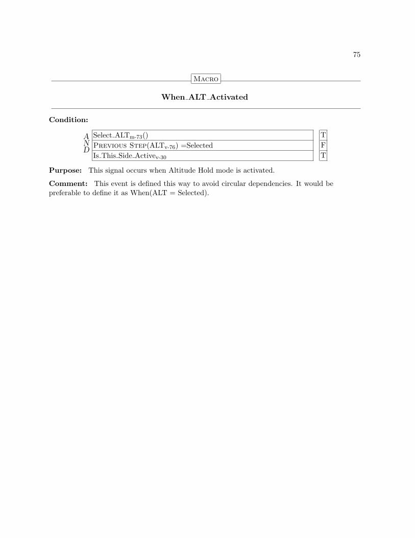
75
Macro
When ALT Activated
Condition:
AND
Select ALTm-73() TPrevious Step(ALTv-76) =Selected FIs This Side Activev-30 T
Purpose: This signal occurs when Altitude Hold mode is activated.
Comment: This event is defined this way to avoid circular dependencies. It would bepreferable to define it as When(ALT = Selected).

76
Definitions of Values to be Encapsulated
State Variable
ALT
Parent: Modesv-34.On
Type: {Cleared, Selected}ty-23
Initial Value: UndefinedClassified as: State:= Offside ALTv-141 if not Is This Side Activev-30
Undefined −→ Cleared if
AND
Select ALTm-73() FIs This Side Activev-30 T
Undefined −→ Selected if
AND
Select ALTm-73() TIs This Side Activev-30 T
Cleared −→ Selected if
AND
Select ALTm-73() TIs This Side Activev-30 T
Selected −→ Cleared if
AND
Deselect ALTm-73() TIs This Side Activev-30 T
Purpose: This variable maintains the current base state of Altitude Hold mode,i.e., whether it is cleared or selected. Note that if this side of the FGS is not active,it obtains its value from the off side. The normal transitions occur only when thisside is active.

77
2.7.2.5 Altitude Select (ALTSEL) Mode
In Altitude Select mode, the FGS provides guidance commands to capture and track thePreselected Altitude. Altitude Select is an arming mode, i.e., after being selected, it mustremained armed for a period of time before it can become active. Altitude Select mode isnormally armed, although it is automically deselected by the activatation of Vertical Approach,Go Around, or Altitude Hold mode. While in the armed state, the FGS monitors the aircraftclosure rate towards the target altitude and determines the optimum capture point to transitionto the capture state. In the capture state, the FGS generates vertical guidance commands toperform a smooth capture of the target altitude. Once it acquires the target altitude, it entersthe track state, during which it generates vertical guidance commands to maintain the aircraftat the target altitude.
Definitions of Values to be Imported
Macro
Select ALTSEL
Condition:
AND
Is VAPPR Activev-87 FIs VGA Activev-92 FIs ALT Activev-74 FModesv-34 =On T
Purpose: This event defines when Altitude Select mode is to be selected, i.e., to becomearmed. Altitude Select mode is armed or active except when Vertical Approach, Go Around, orAltitude Hold are active.

78
Macro
Capture ALTSEL
Condition: When ALTSEL Capture Cond Met Seenm-97()
Purpose: This event defines when Altitude Select mode is to transition from the armed to thecapture state.
Macro
Track ALTSEL
Condition: When ALTSEL Track Cond Met Seenm-96()
Purpose: This event defines when Altitude Select mode is to transition from the capture tothe track state.
Macro
Deselect ALTSEL
Condition:
AND
OR
Is VAPPR Activev-87 T · · ·Is VGA Activev-92 · T · ·Is ALT Activev-74 · · T ·When(Modesv-34 =Off) · · · T
Purpose: This event defines when Altitude Select mode is to be deselected, i.e., to be clearedregardless of whether it is armed or active. Altitude Select mode is armed or active except whenVertical Approach, Go Around, or Altitude Hold are active.
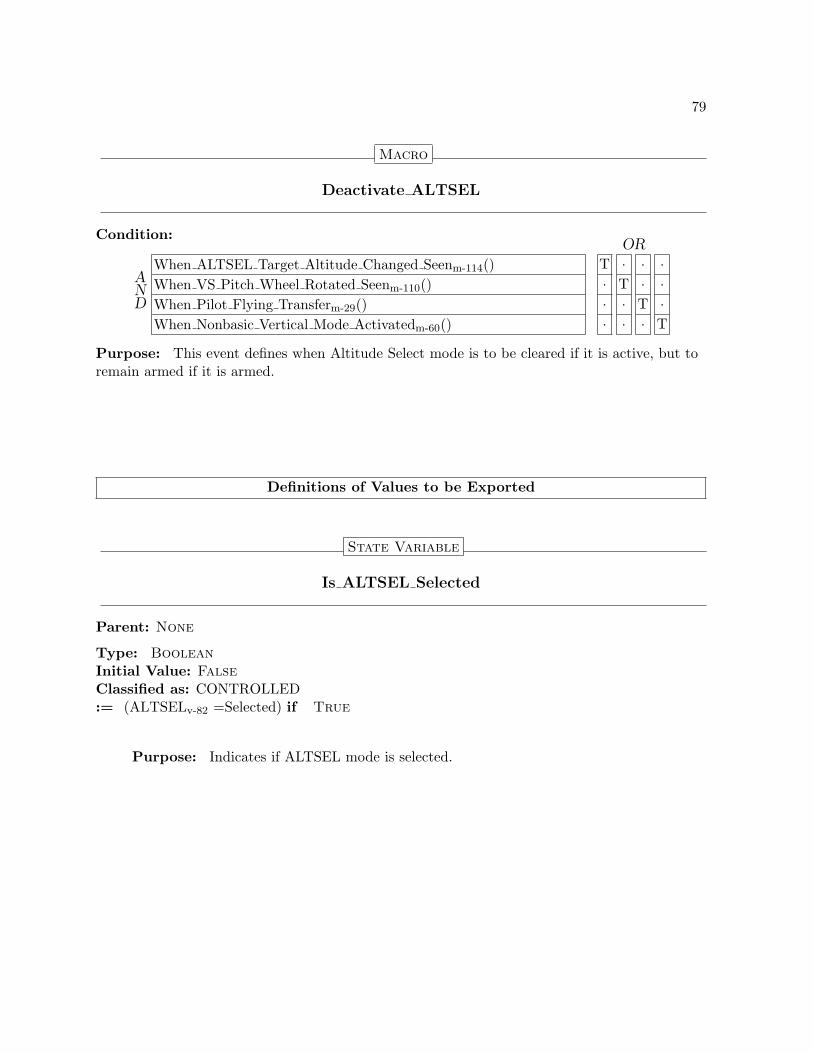
79
Macro
Deactivate ALTSEL
Condition:
AND
OR
When ALTSEL Target Altitude Changed Seenm-114() T · · ·When VS Pitch Wheel Rotated Seenm-110() · T · ·When Pilot Flying Transferm-29() · · T ·When Nonbasic Vertical Mode Activatedm-60() · · · T
Purpose: This event defines when Altitude Select mode is to be cleared if it is active, but toremain armed if it is armed.
Definitions of Values to be Exported
State Variable
Is ALTSEL Selected
Parent: None
Type: BooleanInitial Value: FalseClassified as: CONTROLLED:= (ALTSELv-82 =Selected) if True
Purpose: Indicates if ALTSEL mode is selected.

80
State Variable
Is ALTSEL Active
Parent: None
Type: BooleanInitial Value: FalseClassified as: CONTROLLED:= (ALTSEL Selectedv-83 =Active) if True
Purpose: Indicates if ALTSEL mode is active.
State Variable
Is ALTSEL Track
Parent: None
Type: BooleanInitial Value: FalseClassified as: CONTROLLED:= (ALTSEL Activev-84 =Track) if True
Purpose: Indicates if ALTSEL mode is tracking.

81
Macro
When ALTSEL Activated
Condition:
AND
Capture ALTSELm-78() TPrevious Step(ALTSEL Selectedv-83) =Armed TIs This Side Activev-30 T
Purpose: This signal occurs when Altitude Select mode is activated, i.e., it enters the capturestate.
Comment: This event is defined this way to avoid circular dependencies. It would bepreferable to define it as When(ALTSEL Selected = Active).

82
Definitions of Values to be Encapsulated
State Variable
ALTSEL
Parent: Modesv-34.On
Type: {Cleared, Selected}ty-23
Initial Value: UndefinedClassified as: State:= Offside ALTSELv-141 if not Is This Side Activev-30
Undefined −→ Cleared if
AND
Select ALTSELm-77() FIs This Side Activev-30 T
Undefined −→ Selected if
AND
Select ALTSELm-77() TIs This Side Activev-30 T
Cleared −→ Selected if
AND
Select ALTSELm-77() TIs This Side Activev-30 T
Selected −→ Cleared if
AND
Deselect ALTSELm-78() TIs This Side Activev-30 T
Purpose: This variable maintains the current base state of Altitude Select mode,i.e., whether it is cleared or selected. Note that if this side of the FGS is not active,it obtains its value from the off side. The normal transitions occur only when thisside is active.
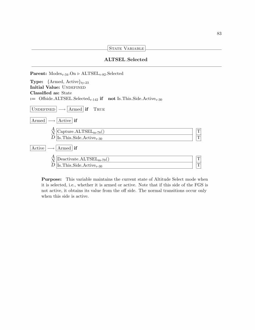
83
State Variable
ALTSEL Selected
Parent: Modesv-34.On . ALTSELv-82.Selected
Type: {Armed, Active}ty-23
Initial Value: UndefinedClassified as: State:= Offside ALTSEL Selectedv-142 if not Is This Side Activev-30
Undefined −→ Armed if True
Armed −→ Active if
AND
Capture ALTSELm-78() TIs This Side Activev-30 T
Active −→ Armed if
AND
Deactivate ALTSELm-79() TIs This Side Activev-30 T
Purpose: This variable maintains the current state of Altitude Select mode whenit is selected, i.e., whether it is armed or active. Note that if this side of the FGS isnot active, it obtains its value from the off side. The normal transitions occur onlywhen this side is active.

84
State Variable
ALTSEL Active
Parent: Modesv-34.On . ALTSELv-82.Selected . ALTSEL Selectedv-83.Active
Type: {Capture, Track}ty-23
Initial Value: UndefinedClassified as: State:= Offside ALTSEL Activev-142 if not Is This Side Activev-30
Undefined −→ Capture if True
Capture −→ Track if Track ALTSELm-78()
Purpose: This variable maintains the current state of Altitude Select mode whenit is active, i.e., whether it is captured or tracking. Note that if this side of the FGSis not active, it obtains its value from the off side. The normal transitions occur onlywhen this side is active.

85
2.7.2.6 Vertical Approach (VAPPR) Mode
In Vertical Approach mode, the FGS provides guidance commands to track vertical guidance forILS precision Glideslope approaches. Vertical Approach is an arming mode, i.e., after beingselected, it must remained armed for a period of time before it can become active.
Definitions of Values to be Imported
Macro
Select VAPPR
Condition: When APPR Switch Pressed Seenm-115()
Purpose: This event defines when Vertical Approach mode is to be selected.
Macro
Activate VAPPR
Condition:
AND
When VAPPR Track Cond Met Seenm-99() TIs LAPPR Activev-52 TOverspeed Conditionm-128() F
Purpose: This event defines when Vertical Approach mode is to transition from the armed tothe active state.

86
Macro
Deselect VAPPR
Condition:
AND
OR
When APPR Switch Pressed Seenm-115() T · · · · ·When(Is LAPPR Selectedv-52 =False) · T · · · ·When Selected Nav Source Changedv-127 · · T · · ·When Selected Nav Frequency Changedv-127 · · · T · ·When Pilot Flying Transferm-29() · · · · T ·When(Modesv-34 =Off) · · · · · T
Purpose: This event defines when Vertical Approach mode is to be deselected, i.e., to becleared regardless of whether it is armed or active.
Macro
Deactivate VAPPR
Condition:
When Nonbasic Vertical Mode Activatedm-60() T
Purpose: This event defines when Vertical Approach mode is to be cleared if it is active, butto remain armed if it is armed.

87
Definitions of Values to be Exported
State Variable
Is VAPPR Selected
Parent: None
Type: BooleanInitial Value: FalseClassified as: CONTROLLED:= (VAPPRv-89 =Selected) if True
Purpose: Indicates if VAPPR mode is selected.
State Variable
Is VAPPR Active
Parent: None
Type: BooleanInitial Value: FalseClassified as: CONTROLLED:= (VAPPR Selectedv-90 =Active) if True
Purpose: Indicates if VAPPR mode is active.

88
Macro
When VAPPR Activated
Condition:
AND
Activate VAPPRm-85() TPrevious Step(VAPPR Selectedv-90) =Armed TIs This Side Activev-30 T
Purpose: This signal occurs when Vertical Approach mode is activated.
Comment: This event is defined this way to avoid circular dependencies. It would bepreferable to define it as When(VAPPR Selected = Active).

89
Definitions of Values to be Encapsulated
State Variable
VAPPR
Parent: Modesv-34.On
Type: {Cleared, Selected}ty-23
Initial Value: UndefinedClassified as: State:= Offside VAPPRv-143 if not Is This Side Activev-30
Undefined −→ Cleared if
AND
Select VAPPRm-85() FIs This Side Activev-30 T
Undefined −→ Selected if
AND
Select VAPPRm-85() TIs This Side Activev-30 T
Cleared −→ Selected if
AND
Select VAPPRm-85() TIs This Side Activev-30 T
Selected −→ Cleared if
AND
OR
Deselect VAPPRm-86() T ·Deactivate VAPPRm-86() · TPrevious Step(VAPPR Selectedv-90) =Active · TIs This Side Activev-30 T T
Purpose: This variable maintains the current base state of Vertical Approachmode, i.e., whether it is cleared or selected. Note that if this side of the FGS is notactive, it obtains its value from the off side. The normal transitions occur only whenthis side is active.
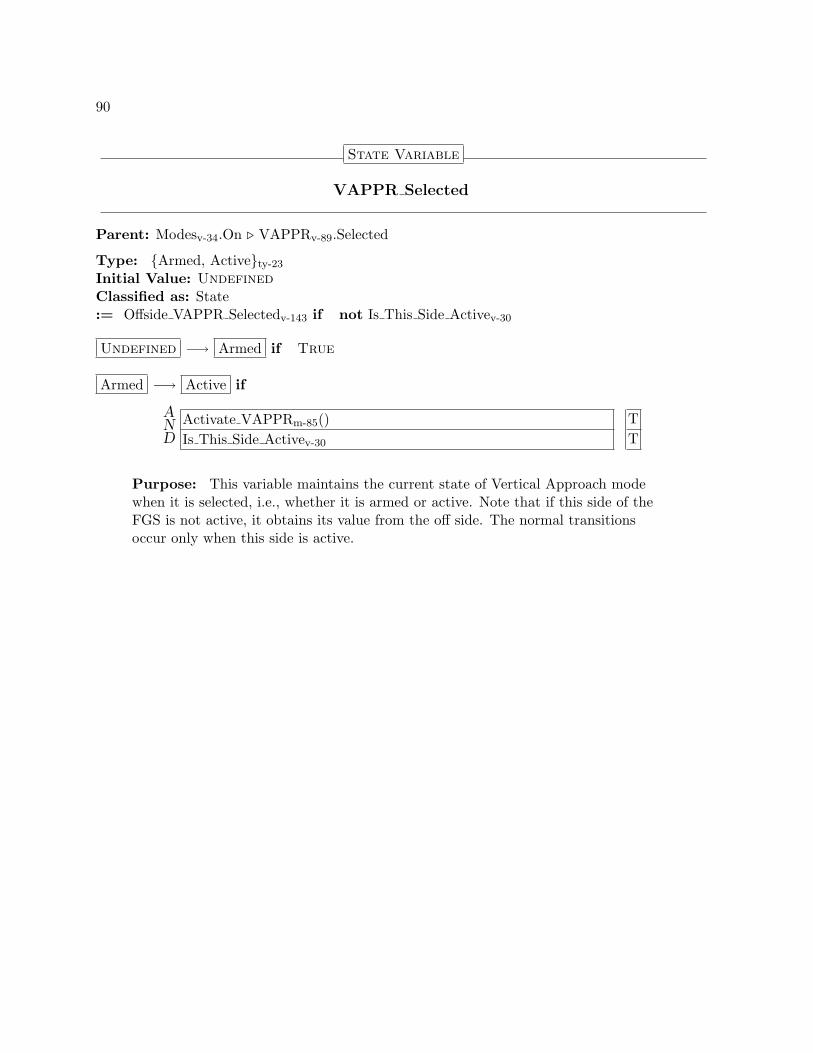
90
State Variable
VAPPR Selected
Parent: Modesv-34.On . VAPPRv-89.Selected
Type: {Armed, Active}ty-23
Initial Value: UndefinedClassified as: State:= Offside VAPPR Selectedv-143 if not Is This Side Activev-30
Undefined −→ Armed if True
Armed −→ Active if
AND
Activate VAPPRm-85() TIs This Side Activev-30 T
Purpose: This variable maintains the current state of Vertical Approach modewhen it is selected, i.e., whether it is armed or active. Note that if this side of theFGS is not active, it obtains its value from the off side. The normal transitionsoccur only when this side is active.
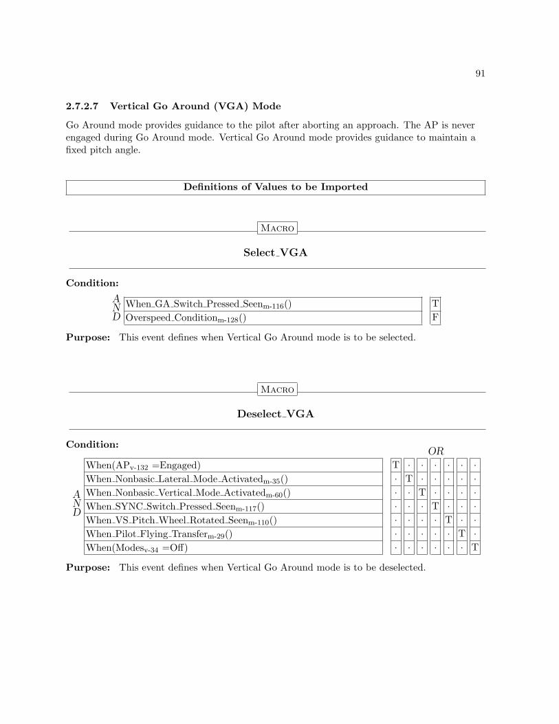
91
2.7.2.7 Vertical Go Around (VGA) Mode
Go Around mode provides guidance to the pilot after aborting an approach. The AP is neverengaged during Go Around mode. Vertical Go Around mode provides guidance to maintain afixed pitch angle.
Definitions of Values to be Imported
Macro
Select VGA
Condition:
AND
When GA Switch Pressed Seenm-116() TOverspeed Conditionm-128() F
Purpose: This event defines when Vertical Go Around mode is to be selected.
Macro
Deselect VGA
Condition:
AND
OR
When(APv-132 =Engaged) T · · · · · ·When Nonbasic Lateral Mode Activatedm-35() · T · · · · ·When Nonbasic Vertical Mode Activatedm-60() · · T · · · ·When SYNC Switch Pressed Seenm-117() · · · T · · ·When VS Pitch Wheel Rotated Seenm-110() · · · · T · ·When Pilot Flying Transferm-29() · · · · · T ·When(Modesv-34 =Off) · · · · · · T
Purpose: This event defines when Vertical Go Around mode is to be deselected.

92
Definitions of Values to be Exported
State Variable
Is VGA Selected
Parent: None
Type: BooleanInitial Value: FalseClassified as: CONTROLLED:= (VGAv-94 =Selected) if True
Purpose: Indicates if VGA mode is selected.
State Variable
Is VGA Active
Parent: None
Type: BooleanInitial Value: FalseClassified as: CONTROLLED:= (VGAv-94 =Selected) if True
Purpose: Indicates if VGA mode is active.
Comment: Even though VGA Selected and VGA Active are the same value, thisis defined to provide a common set of controlled variables across all modes.

93
Macro
When VGA Activated
Condition:
AND
Select VGAm-91() TPrevious Step(VGAv-94) =Selected FIs This Side Activev-30 T
Purpose: This signal occurs when Vertical Go Around mode is activated.
Comment: This event is defined this way to avoid circular dependencies. It would bepreferable to define it as When(LGA = Selected).

94
Definitions of Values to be Encapsulated
State Variable
VGA
Parent: Modesv-34.On
Type: {Cleared, Selected}ty-23
Initial Value: UndefinedClassified as: State:= Offside VGAv-144 if not Is This Side Activev-30
Undefined −→ Cleared if
AND
Select VGAm-91() FIs This Side Activev-30 T
Undefined −→ Selected if
AND
Select VGAm-91() TIs This Side Activev-30 T
Cleared −→ Selected if
AND
Select VGAm-91() TIs This Side Activev-30 T
Selected −→ Cleared if
AND
Deselect VGAm-91() TIs This Side Activev-30 T
Purpose: This variable maintains the current state of Vertical Go Around mode.Note that if this side is not active, it obtains its value from the off side. The normaltransitions for Vertical Go Around mode occur only when this side is active.

95
2.8 Flight Control Laws
The Flight Control Laws generate the pitch and roll guidance commands provided to the FlightDirector and the Autopilot. Different Flight Control Laws are armed or activated based on thecurrent modes of the FGS. They also provide inputs to the mode logic that determine whentransitions are made from the armed to the active state. While the Flight Control Laws are notspecified in this model, this component defines the interface between them and the mode logicand defines the events provided by the Flight Control Laws that the mode logic depends upon.As with events provided by the Flight Control Panel, some of these are prioritized so that ifmultiple events occur at the same time, only the most significant events are seen by the otherparts of the specification.
Definitions of Values to be Exported
Macro
When NAV Track Cond Met
Condition: Is NAV Track Cond Metiv-100
Purpose: This event indicates when the NAV Track Condition is met.
Comment: This is redefined as a macro to simplify verification.
Macro
When NAV Track Cond Met Seen
Condition:
AND
When NAV Track Cond Metm-95() TNo Higher Event Than NAV Track Cond Metm-96() T
Purpose: This event indicates when the NAV Track condition is met and no higher priorityevent has occurred.

96
Macro
No Higher Event Than NAV Track Cond Met
Condition:
AND
When FD Switch Pressedm-103() FNo Higher Event Than FD Switch Pressedm-104() T
Purpose: This event occurs when no event with a priority higher than pressing the NAVswitch has occurred.
Macro
When ALTSEL Track Cond Met
Condition: Is ALTSEL Track Cond Metiv-101
Purpose: This event indicates when the ALTSEL Track Condition is met.
Comment: This is redefined as a macro to simplify verification.
Macro
When ALTSEL Track Cond Met Seen
Condition:
AND
When ALTSEL Track Cond Metm-96() TNo Higher Event Than ALTSEL Track Cond Metm-97() T
Purpose: This event indicates when the ALTSEL Track condition is met and no higherpriority event has occurred.

97
Macro
No Higher Event Than ALTSEL Track Cond Met
Condition:
AND
When FD Switch Pressedm-103() FNo Higher Event Than FD Switch Pressedm-104() T
Purpose: This event occurs when no event with a priority higher than pressing the FD switchhas occurred.
Macro
When ALTSEL Capture Cond Met
Condition: Is ALTSEL Capture Cond Metiv-101
Purpose: This event indicates when the ALTSEL Capture Condition is met.
Comment: This is redefined as a macro to simplify verification.
Macro
When ALTSEL Capture Cond Met Seen
Condition:
AND
When ALTSEL Capture Cond Metm-97() TNo Higher Event Than ALTSEL Capture Cond Metm-98() T
Purpose: This event indicates when the ALTSEL Capture condition is met and no higherpriority event has occurred.

98
Macro
No Higher Event Than ALTSEL Capture Cond Met
Condition:
AND
When FD Switch Pressedm-103() FNo Higher Event Than FD Switch Pressedm-104() T
Purpose: This event occurs when no event with a priority higher than pressing the FD switchhas occurred.
Macro
When LAPPR Track Cond Met
Condition: Is LAPPR Track Cond Metiv-101
Purpose: This event indicates when the LAPPR Track Condition is met.
Comment: This is redefined as a macro to simplify verification.
Macro
When LAPPR Track Cond Met Seen
Condition:
AND
When LAPPR Track Cond Metm-98() TNo Higher Event Than LAPPR Track Cond Metm-99() T
Purpose: This event indicates when the LAPPR Track condition is met and no higherpriority event has occurred.

99
Macro
No Higher Event Than LAPPR Track Cond Met
Condition:
AND
When FD Switch Pressedm-103() FNo Higher Event Than FD Switch Pressedm-104() T
Purpose: This event occurs when no event with a priority higher than pressing the FD switchhas occurred.
Macro
When VAPPR Track Cond Met
Condition: Is VAPPR Track Cond Metiv-102
Purpose: This event indicates when the VAPPR Track Condition is met.
Comment: This is redefined as a macro to simplify verification.
Macro
When VAPPR Track Cond Met Seen
Condition:
AND
When VAPPR Track Cond Metm-99() TNo Higher Event Than VAPPR Track Cond Metm-100() T
Purpose: This event indicates when the VAPPR Track condition is met and no higherpriority event has occurred.

100
Macro
No Higher Event Than VAPPR Track Cond Met
Condition:
AND
When FD Switch Pressedm-103() FNo Higher Event Than FD Switch Pressedm-104() T
Purpose: This event occurs when no event with a priority higher than pressing the FD switchhas occurred.
Definitions of Values to be Encapsulated
Input Variable
Is NAV Track Cond Met
Type: BooleanInitial Value: FalseClassified as: MONITOREDPurpose: This input variable becomes true when the lateral navigation (NAV) flight controllaw transitions from the armed to the track state.

101
Input Variable
Is ALTSEL Capture Cond Met
Type: BooleanInitial Value: FalseClassified as: MONITOREDPurpose: This input variable becomes true when the vertical altitude select flight control lawtransitions from the armed to the capture state.
Input Variable
Is ALTSEL Track Cond Met
Type: BooleanInitial Value: FalseClassified as: MONITOREDPurpose: This input variable becomes true when the vertical altitude select flight control lawtransitions from the capture to the track state.
Input Variable
Is LAPPR Track Cond Met
Type: BooleanInitial Value: FalseClassified as: MONITOREDPurpose: This input variable becomes true when the lateral approach (LAPPR) flight controllaw transitions from the armed to the track state.

102
Input Variable
Is VAPPR Track Cond Met
Type: BooleanInitial Value: FalseClassified as: MONITOREDPurpose: This input variable becomes true when the vertical approach (VAPPR) flightcontrol law transitions from the armed to the track state.
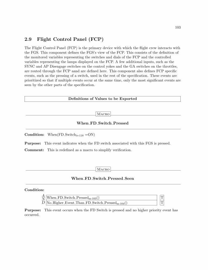
103
2.9 Flight Control Panel (FCP)
The Flight Control Panel (FCP) is the primary device with which the flight crew interacts withthe FGS. This component defines the FGS’s view of the FCP. This consists of the definition ofthe monitored variables representing the switches and dials of the FCP and the controlledvariables representing the lamps displayed on the FCP. A few additional inputs, such as theSYNC and AP Disengage switches on the control yokes and the GA switches on the throttles,are routed through the FCP aand are defined here. This component also defines FCP specificevents, such as the pressing of a switch, used in the rest of the specification. These events areprioritized so that if multiple events occur at the same time, only the most significant events areseen by the other parts of the specification.
Definitions of Values to be Exported
Macro
When FD Switch Pressed
Condition: When(FD Switchiv-118 =ON)
Purpose: This event indicates when the FD switch associated with this FGS is pressed.
Comment: This is redefined as a macro to simplify verification.
Macro
When FD Switch Pressed Seen
Condition:
AND
When FD Switch Pressedm-103() TNo Higher Event Than FD Switch Pressedm-104() T
Purpose: This event occurs when the FD Switch is pressed and no higher priority event hasoccurred.

104
Macro
No Higher Event Than FD Switch Pressed
Condition:
AND
When Transfer Switch Pressedm-104() FNo Higher Event Than Transfer Switch Pressedm-105() T
Purpose: This event occurs when no event with a priority higher than pressing the FD switchhas occurred.
Macro
When Transfer Switch Pressed
Condition: When(Transfer Switchiv-125 =ON)
Purpose: This event indicates when the TRANSFER switch ais pressed.
Comment: This is redefined as a macro to simplify verification.
Macro
When Transfer Switch Pressed Seen
Condition:
AND
When Transfer Switch Pressedm-104() TNo Higher Event Than Transfer Switch Pressedm-105() T
Purpose: This event indicates when the Transfer switch is pressed and no higher priorityevent has occurred.

105
Macro
No Higher Event Than Transfer Switch Pressed
Condition:
AND
When AP Engage Switch Pressedm-105() FNo Higher Event Than AP Engage Switch Pressedm-106() TWhen VS Pitch Wheel Rotatedm-109() FNo Higher Event Than VS Pitch Wheel Rotatedm-110() TWhen NAV Switch Pressedm-107() FNo Higher Event Than NAV Switch Pressedm-108() T
Purpose: This event occurs when no event with a priority higher than pressing the Transferswitch has occurred.
Macro
When AP Engage Switch Pressed
Condition: When(AP Engage Switchiv-126 =ON)
Purpose: This event indicates when the AP Engaged switch is pressed.
Comment: This is redefined as a macro to simplify verification.

106
Macro
When AP Engage Switch Pressed Seen
Condition:
AND
When AP Engage Switch Pressedm-105() TNo Higher Event Than AP Engage Switch Pressedm-106() T
Purpose: This event indicates when the AP Engage switch is pressed and no higher priorityevent has occurred.
Macro
No Higher Event Than AP Engage Switch Pressed
Condition:
AND
When AP Disconnect Switch Pressedm-106() FNo Higher Event Than AP Disconnect Switch Pressedm-107() T
Purpose: This event occurs when no event with a priority higher than pressing the APEngage switch has occurred.
Macro
When AP Disconnect Switch Pressed
Condition: When(AP Disconnect Switchiv-126 =ON)
Purpose: This event indicates when the AP Disconnect switch is pressed.
Comment: This is redefined as a macro to simplify verification.
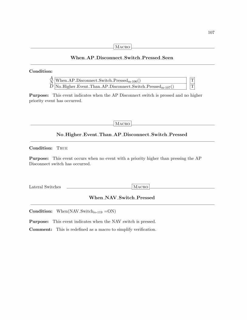
107
Macro
When AP Disconnect Switch Pressed Seen
Condition:
AND
When AP Disconnect Switch Pressedm-106() TNo Higher Event Than AP Disconnect Switch Pressedm-107() T
Purpose: This event indicates when the AP Disconnect switch is pressed and no higherpriority event has occurred.
Macro
No Higher Event Than AP Disconnect Switch Pressed
Condition: True
Purpose: This event occurs when no event with a priority higher than pressing the APDisconnect switch has occurred.
Lateral Switches Macro
When NAV Switch Pressed
Condition: When(NAV Switchiv-119 =ON)
Purpose: This event indicates when the NAV switch is pressed.
Comment: This is redefined as a macro to simplify verification.
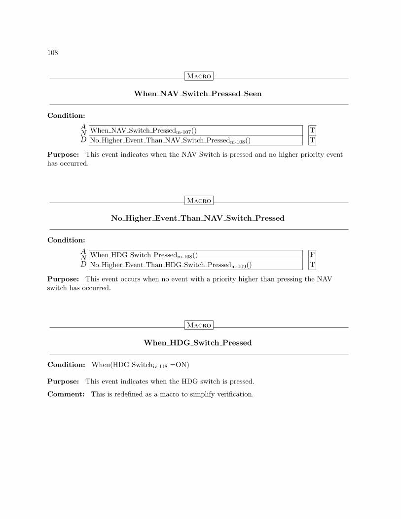
108
Macro
When NAV Switch Pressed Seen
Condition:
AND
When NAV Switch Pressedm-107() TNo Higher Event Than NAV Switch Pressedm-108() T
Purpose: This event indicates when the NAV Switch is pressed and no higher priority eventhas occurred.
Macro
No Higher Event Than NAV Switch Pressed
Condition:
AND
When HDG Switch Pressedm-108() FNo Higher Event Than HDG Switch Pressedm-109() T
Purpose: This event occurs when no event with a priority higher than pressing the NAVswitch has occurred.
Macro
When HDG Switch Pressed
Condition: When(HDG Switchiv-118 =ON)
Purpose: This event indicates when the HDG switch is pressed.
Comment: This is redefined as a macro to simplify verification.

109
Macro
When HDG Switch Pressed Seen
Condition:
AND
When HDG Switch Pressedm-108() TNo Higher Event Than HDG Switch Pressedm-109() T
Purpose: This event indicates when the NAV Switch is pressed and no higher priority eventhas occurred.
Macro
No Higher Event Than HDG Switch Pressed
Condition:
AND
When APPR Switch Pressedm-114() FNo Higher Event Than APPR Switch Pressedm-115() T
Purpose: This event occurs when no event with a priority higher than pressing the HDGswitch has occurred.
Vertical Switches Macro
When VS Pitch Wheel Rotated
Condition: When(VS Pitch Wheel In Motioniv-125)
Purpose: This event indicates when the VS Pitch Wheel is rotated.

110
Macro
When VS Pitch Wheel Rotated Seen
Condition:
AND
When VS Pitch Wheel Rotatedm-109() TNo Higher Event Than VS Pitch Wheel Rotatedm-110() T
Purpose: This event indicates when the VS Pitch Wheel is rotated and no higher priorityevent has occurred.
Macro
No Higher Event Than VS Pitch Wheel Rotated
Condition:
AND
When VS Switch Pressedm-110() FNo Higher Event Than VS Switch Pressedm-111() T
Purpose: This event occurs when no event with a priority higher than rotating the VS PitchWheel has occurred.
Macro
When VS Switch Pressed
Condition: When(VS Switchiv-120 =ON)
Purpose: This event indicates when the VS switch is pressed.
Comment: This is redefined as a macro to simplify verification.
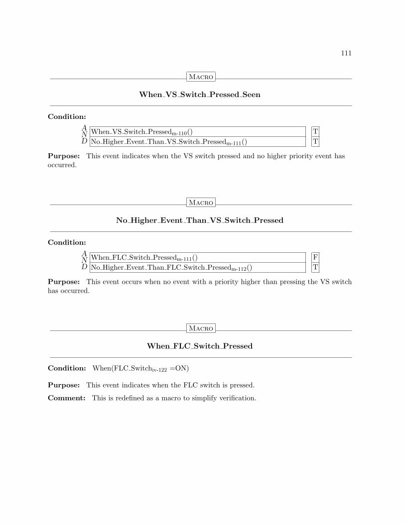
111
Macro
When VS Switch Pressed Seen
Condition:
AND
When VS Switch Pressedm-110() TNo Higher Event Than VS Switch Pressedm-111() T
Purpose: This event indicates when the VS switch pressed and no higher priority event hasoccurred.
Macro
No Higher Event Than VS Switch Pressed
Condition:
AND
When FLC Switch Pressedm-111() FNo Higher Event Than FLC Switch Pressedm-112() T
Purpose: This event occurs when no event with a priority higher than pressing the VS switchhas occurred.
Macro
When FLC Switch Pressed
Condition: When(FLC Switchiv-122 =ON)
Purpose: This event indicates when the FLC switch is pressed.
Comment: This is redefined as a macro to simplify verification.
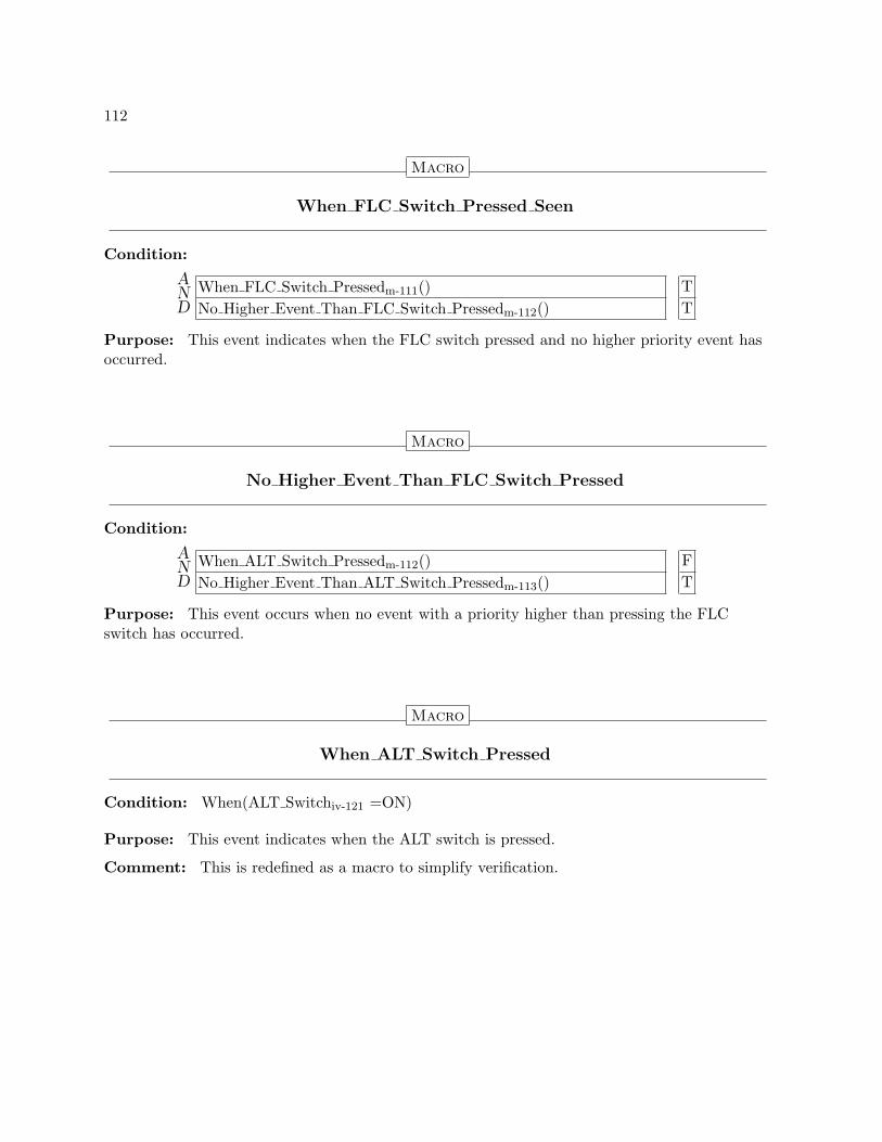
112
Macro
When FLC Switch Pressed Seen
Condition:
AND
When FLC Switch Pressedm-111() TNo Higher Event Than FLC Switch Pressedm-112() T
Purpose: This event indicates when the FLC switch pressed and no higher priority event hasoccurred.
Macro
No Higher Event Than FLC Switch Pressed
Condition:
AND
When ALT Switch Pressedm-112() FNo Higher Event Than ALT Switch Pressedm-113() T
Purpose: This event occurs when no event with a priority higher than pressing the FLCswitch has occurred.
Macro
When ALT Switch Pressed
Condition: When(ALT Switchiv-121 =ON)
Purpose: This event indicates when the ALT switch is pressed.
Comment: This is redefined as a macro to simplify verification.

113
Macro
When ALT Switch Pressed Seen
Condition:
AND
When ALT Switch Pressedm-112() TNo Higher Event Than ALT Switch Pressedm-113() T
Purpose: This event indicates when the ALT switch pressed and no higher priority event hasoccurred.
Macro
No Higher Event Than ALT Switch Pressed
Condition:
AND
When ALTSEL Target Altitude Changedm-113() FNo Higher Event Than ALTSEL Target Altitude Changedm-114() T
Purpose: This event occurs when no event with a priority higher than pressing the ALTswitch has occurred.
Macro
When ALTSEL Target Altitude Changed
Condition:
AND
ALTSEL Target Altitude Changediv-129 =Undefined FALTSEL Target Altitude Changediv-129 T
Purpose: This event indicates when the ALTSEL target altitude is changed.

114
Macro
When ALTSEL Target Altitude Changed Seen
Condition:
AND
When ALTSEL Target Altitude Changedm-113() TNo Higher Event Than ALTSEL Target Altitude Changedm-114() T
Purpose: This event indicates when the ALTSEL target altitude is changed and no higherpriority event has occurred.
Macro
No Higher Event Than ALTSEL Target Altitude Changed
Condition:
AND
When APPR Switch Pressedm-114() FNo Higher Event Than APPR Switch Pressedm-115() T
Purpose: This event occurs when no event with a priority higher than rotating the changingof the ALTSEL target altitude has occurred.
Lateral and Vertical Events Macro
When APPR Switch Pressed
Condition: When(APPR Switchiv-123 =ON)
Purpose: This event indicates when the APPR switch is pressed.
Comment: This is redefined as a macro to simplify verification.

115
Macro
When APPR Switch Pressed Seen
Condition:
AND
When APPR Switch Pressedm-114() TNo Higher Event Than APPR Switch Pressedm-115() T
Purpose: This event indicates when the APPR switch pressed and no higher priority eventhas occurred.
Macro
No Higher Event Than APPR Switch Pressed
Condition:
AND
When GA Switch Pressedm-115() FNo Higher Event Than GA Switch Pressedm-116() T
Purpose: This event occurs when no event with a priority higher than pressing the APPRswitch has occurred.
Macro
When GA Switch Pressed
Condition: When(GA Switchiv-124 =ON)
Purpose: This event indicates when the GA switch is pressed.
Comment: This is redefined as a macro to simplify verification.

116
Macro
When GA Switch Pressed Seen
Condition:
AND
When GA Switch Pressedm-115() TNo Higher Event Than GA Switch Pressedm-116() T
Purpose: This event indicates when the GA switch pressed and no higher priority event hasoccurred.
Macro
No Higher Event Than GA Switch Pressed
Condition:
AND
When SYNC Switch Pressedm-116() FNo Higher Event Than SYNC Switch Pressedm-117() T
Purpose: This event occurs when no event with a priority higher than pressing the GA switchhas occurred.
Macro
When SYNC Switch Pressed
Condition: When(SYNC Switchiv-125 =ON)
Purpose: This event indicates when the SYNC switch is pressed.
Comment: This is redefined as a macro to simplify verification.

117
Macro
When SYNC Switch Pressed Seen
Condition:
AND
When SYNC Switch Pressedm-116() TNo Higher Event Than SYNC Switch Pressedm-117() T
Purpose: This event indicates when the SYNC switch pressed and no higher priority eventhas occurred.
Macro
No Higher Event Than SYNC Switch Pressed
Condition: True
Purpose: This event occurs when no event with a priority higher than pressing the GA switchhas occurred.
Definitions of Values to be Encapsulated
Type
Switch
Possible Values: OFF, ON

118
Type
Lamp
Possible Values: OFF, ON
Input Variable
FD Switch
Type: {OFF, ON}ty-117
Initial Value: UndefinedClassified as: MONITOREDPurpose: Holds the last sensed position of the FD switch associated with this FGS.
Input Variable
HDG Switch
Type: {OFF, ON}ty-117
Initial Value: UndefinedClassified as: MONITOREDPurpose: Holds the last sensed position of the HDG switch.

119
State Variable
HDG Lamp
Parent: None
Type: {OFF, ON}ty-118
Initial Value: OFFClassified as: CONTROLLED:= ON if Is HDG Selectedv-41
:= OFF if not Is HDG Selectedv-41
Purpose: Indicates if the HDG switch lamp on the FCP should be on or off.
Input Variable
NAV Switch
Type: {OFF, ON}ty-117
Initial Value: UndefinedClassified as: MONITOREDPurpose: Holds the last sensed position of the NAV switch.

120
State Variable
NAV Lamp
Parent: None
Type: {OFF, ON}ty-118
Initial Value: OFFClassified as: CONTROLLED:= ON if Is NAV Selectedv-46
:= OFF if not Is NAV Selectedv-46
Purpose: Indicates if the NAV switch lamp should be on or off.
Input Variable
VS Switch
Type: {OFF, ON}ty-117
Initial Value: UndefinedClassified as: MONITOREDPurpose: Holds the last sensed position of the VS switch.

121
State Variable
VS Lamp
Parent: None
Type: {OFF, ON}ty-118
Initial Value: OFFClassified as: CONTROLLED:= ON if Is VS Selectedv-66
:= OFF if not Is VS Selectedv-66
Purpose: Indicates if the VS switch lamp should be on or off.
Input Variable
ALT Switch
Type: {OFF, ON}ty-117
Initial Value: UndefinedClassified as: MONITOREDPurpose: Holds the last sensed position of the ALT switch.
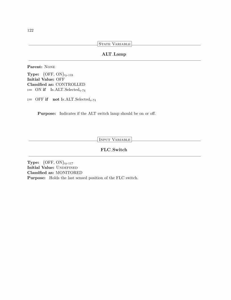
122
State Variable
ALT Lamp
Parent: None
Type: {OFF, ON}ty-118
Initial Value: OFFClassified as: CONTROLLED:= ON if Is ALT Selectedv-74
:= OFF if not Is ALT Selectedv-74
Purpose: Indicates if the ALT switch lamp should be on or off.
Input Variable
FLC Switch
Type: {OFF, ON}ty-117
Initial Value: UndefinedClassified as: MONITOREDPurpose: Holds the last sensed position of the FLC switch.

123
State Variable
FLC Lamp
Parent: None
Type: {OFF, ON}ty-118
Initial Value: OFFClassified as: CONTROLLED:= ON if Is FLC Selectedv-70
:= OFF if not Is FLC Selectedv-70
Purpose: Indicates if the FLC switch lamp should be on or off.
Input Variable
APPR Switch
Type: {OFF, ON}ty-117
Initial Value: UndefinedClassified as: MONITOREDPurpose: Holds the last sensed position of the APPR switch.

124
State Variable
APPR Lamp
Parent: None
Type: {OFF, ON}ty-118
Initial Value: OFFClassified as: CONTROLLED:= ON if
AND
OR
Is LAPPR Selectedv-52 T ·Is VAPPR Selectedv-87 · T
:= OFF if
AND
Is LAPPR Selectedv-52 FIs VAPPR Selectedv-87 F
Purpose: Indicates if the APPR switch lamp should be on or off.
Input Variable
GA Switch
Type: {OFF, ON}ty-117
Initial Value: UndefinedClassified as: MONITOREDPurpose: Holds the last sensed position of the GA switch.

125
Input Variable
SYNC Switch
Type: {OFF, ON}ty-117
Initial Value: UndefinedClassified as: MONITOREDPurpose: Holds the last sensed position of the SYNC switch.
Input Variable
Transfer Switch
Type: {OFF, ON}ty-117
Initial Value: UndefinedClassified as: MONITOREDPurpose: Holds the last sensed position of the TRANSFER switch.
Input Variable
VS Pitch Wheel In Motion
Type: BooleanInitial Value: UndefinedClassified as: MONITOREDPurpose: Holds the last sensed position of the VS/Pitch wheel.

126
Input Variable
AP Engage Switch
Type: {OFF, ON}ty-117
Initial Value: UndefinedClassified as: MONITOREDPurpose: Holds the last sensed position of the AP Engage switch.
State Variable
AP Lamp
Parent: None
Type: {OFF, ON}ty-118
Initial Value: OFFClassified as: CONTROLLED:= ON if Is AP Engagedv-131
:= OFF if not Is AP Engagedv-131
Purpose: Indicates if the AP switch lamp should be on or off.
Input Variable
AP Disconnect Switch
Type: {OFF, ON}ty-117
Initial Value: UndefinedClassified as: MONITOREDPurpose: Holds the last sensed position of the AP Disconnect switch.

127
2.10 Navigation Sources
The FGS receives navigation information from several sources, including VHF Omni-DirectionalRange (VOR) for lateral navigation, Localizer (LOC) for precision lateral approach, andGlideslope (GS) for precision vertical approach. This component defines the FGS’s view of itsnavigation sources. This includes definition of the types of sources available, the currentlyselected source, and the information available from that source.
Definitions of Values to be Exported
State Variable
When Selected Nav Source Changed
Parent: None
Type: BooleanInitial Value: FalseClassified as: MONITOREDPurpose: This event occurs when a new navigation source is selected.
State Variable
When Selected Nav Frequency Changed
Parent: None
Type: BooleanInitial Value: FalseClassified as: MONITOREDPurpose: This event occurs when the frequency of the selected navigation source is changed.

128
2.11 Air Data System
The Air Data System provides information about the aircraft state sensed from the surroundingair mass such as whether an overspeed condition exists. This component defines the FGS’s viewof the Air Data System.
Definitions of Values to be Exported
Macro
Overspeed Condition
Condition:
AND
Overspeediv-128 6=Undefined TOverspeediv-128 =True T
Definitions of Values to be Encapsulated
Input Variable
Overspeed
Type: BooleanInitial Value: UndefinedClassified as: MONITOREDPurpose: This state variable indicates if an overspeed condition exists.
129
2.12 References
References refer to target values used by several of the modes, such as the Preselected Altitude.These may be set by the flight crew through the Flight Control Panel, or set to the currentaircraft value on entry to a mode or a synchronization request. The references may bephysically maintained by a variety of systems. This component defines the FGS’s view of thereferences. Details of how these values are obtained from other systems are encapsulated withinthis component.
Definitions of Values to be Exported
Input Variable
ALTSEL Target Altitude Changed
Type: BooleanInitial Value: TrueClassified as: MONITOREDPurpose: This input variable holds the most recent information on whether the ALTSELtarget altitude (either the PSA or FPTA) has been changed.

130
2.13 Autopilot (AP)
The Autopilot (AP) commands movement of the control surfaces based on the pitch and rollcommands generated by the FGS. This component defines the FGS’s view of the AP.
Definitions of Values to be Imported
Macro
When Engage AP
Condition: When AP Engage Switch Pressed Seenm-106()
Purpose: This event defines when the AP is to be engaged.
Macro
When Disengage AP
Condition:
AND
OR
When AP Engage Switch Pressed Seenm-106() T · ·When AP Disconnect Switch Pressed Seenm-107() · T ·When GA Switch Pressed Seenm-116() · · T
Purpose: This event defines when the AP is to be disengaged.

131
Definitions of Values to be Exported
State Variable
Is AP Engaged
Parent: None
Type: BooleanInitial Value: FalseClassified as: CONTROLLED:= (APv-132 =Engaged) if True
Purpose: Indicates if the AP is engaged.
Definitions of Values to be Encapsulated
Type
AP State
Possible Values: Disengaged, Engaged

132
State Variable
AP
Parent: None
Type: {Disengaged, Engaged}ty-131
Initial Value: DisengagedClassified as: StateDisengaged −→ Engaged if When Engage APm-130()
Engaged −→ Disengaged if When Disengage APm-130()
Purpose: This variable maintains the current state of the autopilot.

133
2.14 Offside FGS
The FGS has two physical sides, or channels, on the left and right sides of the aircraft. Theseprovide redundant implementations that communicate with each other over a cross-channel bus.This component defines this side of the FGS’s view of the other side.
Definitions of Values to be Exported
State Variable
Offside FD
Parent: None
Type: {Off, On}ty-23
Initial Value: OffClassified as: MONITORED:= Off if not Offside FD Oniv-145
:= On if Offside FD Oniv-145
Purpose: This variable holds the most recent information on the state of the FDon the offside FD.

134
State Variable
Is Offside LAPPR Active
Parent: None
Type: BooleanInitial Value: FalseClassified as: MONITORED:= Offside LAPPR Selectedv-138 =Active if True
Purpose: Indicates if offside LAPPR mode is active.
State Variable
Is Offside VAPPR Active
Parent: None
Type: BooleanInitial Value: FalseClassified as: MONITORED:= Offside VAPPR Selectedv-143 =Active if True
Purpose: Indicates if offside VAPPR mode is active.

135
State Variable
Is Offside VGA Active
Parent: None
Type: BooleanInitial Value: FalseClassified as: MONITORED:= Offside VGAv-144 =Selected if True
Purpose: Indicates if offside VGA mode is active.
State Variable
Offside Modes
Parent: None
Type: {Off, On}ty-23
Initial Value: OffClassified as: MONITORED:= Off if not Offside Modes Oniv-145
:= On if Offside Modes Oniv-145
Purpose: This variable holds the most recent information on the state of themode annunciations on the offside FGS.

136
State Variable
Offside ROLL
Parent: Offside Modesv-135.On
Type: {Cleared, Selected}ty-23
Initial Value: UndefinedClassified as: MONITORED:= Cleared if not Offside Roll Selectediv-145
:= Selected if Offside Roll Selectediv-145
Purpose: This variable holds the most recent information on the base state of thelateral ROLL mode of the offside FGS.
State Variable
Offside HDG
Parent: Offside Modesv-135.On
Type: {Cleared, Selected}ty-23
Initial Value: UndefinedClassified as: MONITORED:= Cleared if not Offside Hdg Selectediv-146
:= Selected if Offside Hdg Selectediv-146
Purpose: This variable holds the most recent information on the base state of thelateral HDG mode of the offside FGS.

137
State Variable
Offside NAV
Parent: Offside Modesv-135.On
Type: {Cleared, Selected}ty-23
Initial Value: UndefinedClassified as: MONITORED:= Cleared if not Offside Nav Selectediv-146
:= Selected if Offside Nav Selectediv-146
Purpose: This variable holds the most recent information on the base state of thelateral NAV mode of the offside FGS.
State Variable
Offside NAV Selected
Parent: Offside Modesv-135.On . Offside NAVv-137.Selected
Type: {Armed, Active}ty-23
Initial Value: UndefinedClassified as: MONITORED:= Armed if not Offside Nav Activeiv-146
:= Active if Offside Nav Activeiv-146
Purpose: This variable holds the most recent information on the selected state ofthe lateral NAV mode of the offside FGS.
138
State Variable
Offside LAPPR
Parent: Offside Modesv-135.On
Type: {Cleared, Selected}ty-23
Initial Value: UndefinedClassified as: MONITORED:= Cleared if not Offside Lappr Selectediv-147
:= Selected if Offside Lappr Selectediv-147
Purpose: This variable holds the most recent information on the base state of thelateral APPR mode of the offside FGS.
State Variable
Offside LAPPR Selected
Parent: Offside Modesv-135.On . Offside LAPPRv-138.Selected
Type: {Armed, Active}ty-23
Initial Value: UndefinedClassified as: MONITORED:= Armed if not Offside Lappr Activeiv-147
:= Active if Offside Lappr Activeiv-147
Purpose: This variable holds the most recent information on the selected state ofthe lateral APPR mode of the offside FGS.

139
State Variable
Offside LGA
Parent: Offside Modesv-135.On
Type: {Cleared, Selected}ty-23
Initial Value: UndefinedClassified as: MONITORED:= Cleared if not Offside Lga Selectediv-147
:= Selected if Offside Lga Selectediv-147
Purpose: This variable holds the most recent information on the base state of thelateral GA mode of the offside FGS.
State Variable
Offside PITCH
Parent: Offside Modesv-135.On
Type: {Cleared, Selected}ty-23
Initial Value: UndefinedClassified as: MONITORED:= Cleared if not Offside Pitch Selectediv-148
:= Selected if Offside Pitch Selectediv-148
Purpose: This variable holds the most recent information on the base state of thevertical PITCH mode of the offside FGS.

140
State Variable
Offside VS
Parent: Offside Modesv-135.On
Type: {Cleared, Selected}ty-23
Initial Value: UndefinedClassified as: MONITORED:= Cleared if not Offside Vs Selectediv-148
:= Selected if Offside Vs Selectediv-148
Purpose: This variable holds the most recent information on the base state of thevertical VS mode of the offside FGS.
State Variable
Offside FLC
Parent: Offside Modesv-135.On
Type: {Cleared, Selected}ty-23
Initial Value: UndefinedClassified as: MONITORED:= Cleared if not Offside Flc Selectediv-148
:= Selected if Offside Flc Selectediv-148
Purpose: This variable holds the most recent information on the base state of thevertical FLC mode of the offside FGS.

141
State Variable
Offside ALT
Parent: Offside Modesv-135.On
Type: {Cleared, Selected}ty-23
Initial Value: UndefinedClassified as: MONITORED:= Cleared if not Offside Alt Selectediv-149
:= Selected if Offside Alt Selectediv-149
Purpose: This variable holds the most recent information on the base state of thevertical ALT mode of the offside FGS.
State Variable
Offside ALTSEL
Parent: Offside Modesv-135.On
Type: {Cleared, Selected}ty-23
Initial Value: UndefinedClassified as: MONITORED:= Cleared if not Offside Altsel Selectediv-149
:= Selected if Offside Altsel Selectediv-149
Purpose: This variable holds the most recent information on the base state of thevertical ALTSEL mode of the offside FGS.
142
State Variable
Offside ALTSEL Selected
Parent: Offside Modesv-135.On . Offside ALTSELv-141.Selected
Type: {Armed, Active}ty-23
Initial Value: UndefinedClassified as: MONITORED:= Armed if not Offside Altsel Activeiv-149
:= Active if Offside Altsel Activeiv-149
Purpose: This variable holds the most recent information on the selected state ofthe vertical ALTSEL mode of the offside FGS.
State Variable
Offside ALTSEL Active
Parent:Offside Modesv-135.On . Offside ALTSELv-141.Selected . Offside ALTSEL Selectedv-142.Active
Type: {Capture, Track}ty-23
Initial Value: UndefinedClassified as: MONITORED:= Capture if not Offside Altsel Trackiv-150
:= Track if Offside Altsel Trackiv-150
Purpose: This variable holds the most recent information on the active state ofthe vertical ALTSEL mode of the offside FGS.

143
State Variable
Offside VAPPR
Parent: Offside Modesv-135.On
Type: {Cleared, Selected}ty-23
Initial Value: UndefinedClassified as: MONITORED:= Cleared if not Offside Vappr Selectediv-150
:= Selected if Offside Vappr Selectediv-150
Purpose: This variable holds the most recent information on the base state of thevertical APPR mode of the offside FGS.
State Variable
Offside VAPPR Selected
Parent: Offside Modesv-135.On . Offside VAPPRv-143.Selected
Type: {Armed, Active}ty-23
Initial Value: UndefinedClassified as: MONITORED:= Armed if not Offside Vappr Activeiv-150
:= Active if Offside Vappr Activeiv-150
Purpose: This variable holds the most recent information on the selected state ofthe vertical APPR mode of the offside FGS.

144
State Variable
Offside VGA
Parent: Offside Modesv-135.On
Type: {Cleared, Selected}ty-23
Initial Value: UndefinedClassified as: MONITORED:= Cleared if not Offside Vga Selectediv-151
:= Selected if Offside Vga Selectediv-151
Purpose: This variable holds the most recent information on the base state of thevertical GA mode of the offside FGS.
Definitions of Values to be Encapsulated
Input Variable
Offside FGS Active
Type: BooleanInitial Value: UndefinedClassified as: InputPurpose: This input variable holds the most recent information on whether the offside FGSbelieves it is active.

145
Input Variable
Offside FD On
Type: BooleanInitial Value: UndefinedClassified as: InputPurpose: This input variable holds the most recent information on whether the offside FD isturned on.
Input Variable
Offside Modes On
Type: BooleanInitial Value: UndefinedClassified as: InputPurpose: This input variable holds the most recent information on whether the offside modesare on.
Input Variable
Offside Roll Selected
Type: BooleanInitial Value: UndefinedClassified as: InputPurpose: This input variable holds the most recent information on whether the offside ROLLmode is selected.

146
Input Variable
Offside Hdg Selected
Type: BooleanInitial Value: UndefinedClassified as: InputPurpose: This input variable holds the most recent information on whether the offsideHeading mode is selected.
Input Variable
Offside Nav Selected
Type: BooleanInitial Value: UndefinedClassified as: InputPurpose: This input variable holds the most recent information on whether the offside Navmode is selected.
Input Variable
Offside Nav Active
Type: BooleanInitial Value: UndefinedClassified as: InputPurpose: This input variable holds the most recent information on whether the offside Navmode is active.

147
Input Variable
Offside Lappr Selected
Type: BooleanInitial Value: UndefinedClassified as: InputPurpose: This input variable holds the most recent information on whether the offside Lapprmode is selected.
Input Variable
Offside Lappr Active
Type: BooleanInitial Value: UndefinedClassified as: InputPurpose: This input variable holds the most recent information on whether the offside Lapprmode is active.
Input Variable
Offside Lga Selected
Type: BooleanInitial Value: UndefinedClassified as: InputPurpose: This input variable holds the most recent information on whether the offside Lgamode is selected.

148
Input Variable
Offside Pitch Selected
Type: BooleanInitial Value: UndefinedClassified as: InputPurpose: This input variable holds the most recent information on whether the offsidevertical Pitch mode is selected.
Input Variable
Offside Vs Selected
Type: BooleanInitial Value: UndefinedClassified as: InputPurpose: This input variable holds the most recent information on whether the offsidevertical Speed mode is selected.
Input Variable
Offside Flc Selected
Type: BooleanInitial Value: UndefinedClassified as: InputPurpose: This input variable holds the most recent information on whether the offsidevertical Flight Level Change mode is selected.

149
Input Variable
Offside Alt Selected
Type: BooleanInitial Value: UndefinedClassified as: InputPurpose: This input variable holds the most recent information on whether the offsidevertical Altitude Hold mode is selected.
Input Variable
Offside Altsel Selected
Type: BooleanInitial Value: UndefinedClassified as: InputPurpose: This input variable holds the most recent information on whether the offsidevertical Altitude Select mode is selected.
Input Variable
Offside Altsel Active
Type: BooleanInitial Value: UndefinedClassified as: InputPurpose: This input variable holds the most recent information on whether the offsidevertical Altitude Select mode is active.

150
Input Variable
Offside Altsel Track
Type: BooleanInitial Value: UndefinedClassified as: InputPurpose: This input variable holds the most recent information on whether the offsidevertical Altitude Select mode is tracking.
Input Variable
Offside Vappr Selected
Type: BooleanInitial Value: UndefinedClassified as: InputPurpose: This input variable holds the most recent information on whether the offside Vapprmode is selected.
Input Variable
Offside Vappr Active
Type: BooleanInitial Value: UndefinedClassified as: InputPurpose: This input variable holds the most recent information on whether the offside Vapprmode is active.

151
Input Variable
Offside Vga Selected
Type: BooleanInitial Value: UndefinedClassified as: InputPurpose: This input variable holds the most recent information on whether the offside Vgamode is selected.

152
2.15 FGS Inputs
This section defines the physical interface for all inputs to the FGS. The input variablesassociated with these fields are defined in the part of the specification to which they arelogically related.
Message
Other Input Msg
Fields: AltSel is Boolean
, AltselAct is Boolean
, AltselSel is Boolean
, AltselTrk is Boolean
, FdOn is Boolean
, FGSActive is Boolean
, FlcSel is Boolean
, HdgSel is Boolean
, LapprAct is Boolean
, LapprSel is Boolean
, LgaSel is Boolean
, ModesOn is Boolean
, NavAct is Boolean
, NavSel is Boolean
, PthSel is Boolean
, RollSel is Boolean
, VapprAct is Boolean
, VapprSel is Boolean
, VgaSel is Boolean
, VsSel is Boolean
Message
This Input Msg

153
Fields: AltPreRefChanged is Boolean
, AltselCaptureCondMet is Boolean
, AltselTargetAltChanged is Boolean
, AltselTrackCondMet is Boolean
, AltSwi is {OFF, ON}ty-117
, ApDiscSwi is {OFF, ON}ty-117
, ApEngSwi is {OFF, ON}ty-117
, ApprSwi is {OFF, ON}ty-117
, FdSwi is {OFF, ON}ty-117
, FlcSwi is {OFF, ON}ty-117
, GaSwi is {OFF, ON}ty-117
, HdgSwi is {OFF, ON}ty-117
, LapprTrackCondMet is Boolean
, NavSwi is {OFF, ON}ty-117
, NavTrackCondMet is Boolean
, Overspeed is Boolean
, SyncSwi is {OFF, ON}ty-117
, TransSwi is {OFF, ON}ty-117
, VapprTrackCondMet is Boolean
, VsPthWhlMot is Boolean
, VsSwi is {OFF, ON}ty-117
Input Interface
Other Input
Min. Separation: UndefinedMax. Separation: UndefinedInput Action: Read(Other Input Msgm-152 )
HandlerGuard Condition: True

154
Assignment(s) Offside Alt Selectediv-149 is assigned AltSelOffside Altsel Activeiv-149 is assigned AltselActOffside Altsel Selectediv-149 is assigned AltselSelOffside Altsel Trackiv-150 is assigned AltselTrkOffside FD Oniv-145 is assigned FdOnOffside FGS Activeiv-144 is assigned FGSActiveOffside Flc Selectediv-148 is assigned FlcSelOffside Hdg Selectediv-146 is assigned HdgSelOffside Lappr Selectediv-147 is assigned LapprSelOffside Lappr Activeiv-147 is assigned LapprActOffside Lga Selectediv-147 is assigned LgaSelOffside Modes Oniv-145 is assigned ModesOnOffside Nav Activeiv-146 is assigned NavActOffside Nav Selectediv-146 is assigned NavSelOffside Pitch Selectediv-148 is assigned PthSelOffside Roll Selectediv-145 is assigned RollSelOffside Vappr Selectediv-150 is assigned VapprSelOffside Vappr Activeiv-150 is assigned VapprActOffside Vga Selectediv-151 is assigned VgaSelOffside Vs Selectediv-148 is assigned VsSel

155
Input Interface
This Input
Min. Separation: UndefinedMax. Separation: UndefinedInput Action: Read(This Input Msgm-152 )
HandlerGuard Condition: True
Assignment(s)Is ALTSEL Capture Cond Metiv-101 is assigned AltselCaptureCondMetALTSEL Target Altitude Changediv-129 is assigned AltselTargetAltChangedIs ALTSEL Track Cond Metiv-101 is assigned AltselTrackCondMetALT Switchiv-121 is assigned AltSwiAP Disconnect Switchiv-126 is assigned ApDiscSwiAP Engage Switchiv-126 is assigned ApEngSwiAPPR Switchiv-123 is assigned ApprSwiFD Switchiv-118 is assigned FdSwiFLC Switchiv-122 is assigned FlcSwiGA Switchiv-124 is assigned GaSwiHDG Switchiv-118 is assigned HdgSwiIs LAPPR Track Cond Metiv-101 is assigned LapprTrackCondMetNAV Switchiv-119 is assigned NavSwiIs NAV Track Cond Metiv-100 is assigned NavTrackCondMetOverspeediv-128 is assigned Overspeediv-128
SYNC Switchiv-125 is assigned SyncSwiTransfer Switchiv-125 is assigned TransSwiIs VAPPR Track Cond Metiv-102 is assigned VapprTrackCondMetVS Pitch Wheel In Motioniv-125 is assigned VsPthWhlMotVS Switchiv-120 is assigned VsSwi

156
2.16 FGS Outputs
This section defines the physical interface for all outputs from the FGS. The output variablesassociated with these fields are defined in the part of the specification to which they arelogically related.
Message
This Output Msg
Fields: AltLamp is {OFF, ON}ty-118
, AltSel is Boolean
, AltselAct is Boolean
, AltselSel is Boolean
, AltselTrk is Boolean
, ApEng is Boolean
, ApLamp is {OFF, ON}ty-118
, ApprLamp is {OFF, ON}ty-118
, FdOn is Boolean
, FGSActive is Boolean
, FlcLamp is {OFF, ON}ty-118
, FlcSel is Boolean
, HdgLamp is {OFF, ON}ty-118
, HdgSel is Boolean
, LapprAct is Boolean
, LapprSel is Boolean
, LgaSel is Boolean
, ModesOn is Boolean
, NavAct is Boolean
, NavLamp is {OFF, ON}ty-118
, NavSel is Boolean
, PilotFlying is {LEFT, RIGHT}ty-23
, PthSel is Boolean
, RollSel is Boolean
, VapprAct is Boolean
, VapprSel is Boolean
, VgaSel is Boolean
, VsLamp is {OFF, ON}ty-118
, VsSel is Boolean

157
Macro
When Lateral Mode Changed
Condition:
AND
OR
Changed(Is ROLL Selectedv-38) T · · · · · ·Changed(Is HDG Selectedv-41) · T · · · · ·Changed(Is NAV Selectedv-46) · · T · · · ·Changed(Is NAV Activev-46) · · · T · · ·Changed(Is LAPPR Selectedv-52) · · · · T · ·Changed(Is LAPPR Activev-52) · · · · · T ·Changed(Is LGA Selectedv-57) · · · · · · T
Macro
When Vertical Mode Changed
Condition:
AND
OR
Changed(Is PITCH Selectedv-63) T · · · · · · · · ·Changed(Is VS Selectedv-66) · T · · · · · · · ·Changed(Is ALT Selectedv-74) · · T · · · · · · ·Changed(Is ALTSEL Selectedv-79) · · · T · · · · · ·Changed(Is ALTSEL Activev-80) · · · · T · · · · ·Changed(Is ALTSEL Trackv-80) · · · · · T · · · ·Changed(Is FLC Selectedv-70) · · · · · · T · · ·Changed(Is VAPPR Selectedv-87) · · · · · · · T · ·Changed(Is VAPPR Activev-87) · · · · · · · · T ·Changed(Is VGA Selectedv-92) · · · · · · · · · T
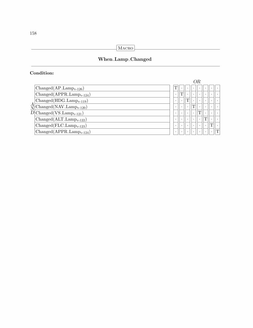
158
Macro
When Lamp Changed
Condition:
AND
OR
Changed(AP Lampv-126) T · · · · · · ·Changed(APPR Lampv-124) · T · · · · · ·Changed(HDG Lampv-119) · · T · · · · ·Changed(NAV Lampv-120) · · · T · · · ·Changed(VS Lampv-121) · · · · T · · ·Changed(ALT Lampv-122) · · · · · T · ·Changed(FLC Lampv-123) · · · · · · T ·Changed(APPR Lampv-124) · · · · · · · T

159
Output Interface
This Output
Min. Separation: UndefinedMax. Separation: UndefinedOutput Action: Publish(This Output Msgm-156 )
HandlerGuard Condition:
AND
OR
Changed(Mode Annunciations Onv-33) T · · · · · · ·Changed(Pilot Flyingv-29) · T · · · · · ·Changed(Onside FD Onv-28) · · T · · · · ·Changed(Is This Side Activev-30) · · · T · · · ·Changed(Is AP Engagedv-131) · · · · T · · ·When Lateral Mode Changedm-157() · · · · · T · ·When Vertical Mode Changedm-157() · · · · · · T ·When Lamp Changedm-158() · · · · · · · T

160
Assignment(s) AltLamp is assigned ALT Lampv-122
AltSel is assigned Is ALT Selectedv-74
AltselAct is assigned Is ALTSEL Activev-80
AltselSel is assigned Is ALTSEL Selectedv-79
AltselTrk is assigned Is ALTSEL Trackv-80
ApEng is assigned Is AP Engagedv-131
ApLamp is assigned AP Lampv-126
ApprLamp is assigned APPR Lampv-124
FdOn is assigned Onside FD Onv-28
FGSActive is assigned Is This Side Activev-30
FlcLamp is assigned FLC Lampv-123
FlcSel is assigned Is FLC Selectedv-70
HdgLamp is assigned HDG Lampv-119
HdgSel is assigned Is HDG Selectedv-41
LapprSel is assigned Is LAPPR Selectedv-52
LapprAct is assigned Is LAPPR Activev-52
LgaSel is assigned Is LGA Selectedv-57
ModesOn is assigned Mode Annunciations Onv-33
NavAct is assigned Is NAV Activev-46
NavLamp is assigned NAV Lampv-120
NavSel is assigned Is NAV Selectedv-46
PilotFlying is assigned Pilot Flyingv-29
PthSel is assigned Is PITCH Selectedv-63
RollSel is assigned Is ROLL Selectedv-38
VapprSel is assigned Is VAPPR Selectedv-87
VapprAct is assigned Is VAPPR Activev-87
VgaSel is assigned Is VGA Selectedv-92
VsLamp is assigned VS Lampv-121
VsSel is assigned Is VS Selectedv-66
Action: Send

Bibliography
[1] Anonymous. Mission critical systems: Defense attempting to address major softwarechallenges. Technical Report GAO/IMTEC-93-13, U.S. General Accounting Office, 1992.
[2] Anonymous. Joint advisory circular: Flight guidance system approval. Technical ReportAC/ACJ 25.1329, Federal Aviation Administration, 2001.
[3] Barry Boehm. Prentice-Hall, Englewood Cliffs, NJ, 1981.
[4] Fred Brooks. No silver bullet: : Essence and accidents of software engineering. IEEEComputer, pages 10–19, April 1997.
[5] David Harel and Amnon Naamad. The STATEMATE semantics of statecharts. ACMTransactions on Software Engineering and Methodology (TOSEM), 5(4):293–333, October1996.
[6] Matts Heimdahl and Nancy G. Leveson. Completeness and consistency in hierarchicalstate-based requirements. IEEE Transactions on Software Engineering, 22(6):363–377,June 1996.
[7] Constance L. Heitmeyer, James Kirby, , and Bruce G. Labaw. Automated consistencychecking of requirements specification. ACM Transactions on Software Engineering andMethodology (TOSEM), 5(3):231–261, July 1996.
[8] Nancy Leveson, Matts Heimdahl, Holly Hildreth, and Jon Reese. Requirementsspecifications for process-control systems. IEEE Transactions on Software Engineering,20(9):684–707, September 1994.
[9] Nancy Leveson, Denise Pinnel, Sean Sandys, Shuichi Koga, and Jon Reese. Analyzingsoftware specifications for mode confusion potential. 1997.
[10] Nancy Leveson, Sean Sandys, Denise Pinnel, Susan Joslyn, Liliana Alfaro, Zelda Zabinsky,and Alan Shaw. Safety analysis of air traffic control upgrades. Technical report, SafewareEngineering, 1997.
[11] Nancy G. Leveson. Addison-Wesley Publishing Company, Reading, Massachusetts, 1995.
161

162
[12] Robyn Lutz. Analyzing software requirements errors in safety-critical, embedded systems.In IEEE Symposium on Requirements Engineering, San Diego, CA, 1993.
[13] Steven P. Miller. Specifying the mode logic of a flight guidance system in core and scr. InSecond Workshop on Formal Methods in Software Practice (FMSP98), Clearwater Beach,Florida, 1998.
[14] E. H. Phillip. Global teamwork called key to improving aviation safety. Aviation Week &Space Technology, page 70, July 2001.

Index
ALTSEL (State Variable)Definition, 82Reference(s), 79, 83, 84
ALT (State Variable)Definition, 76Reference(s), 74, 75
ALT Lamp (State Variable)Definition, 122Reference(s), 158, 160
ALT Switch (Input Variable)Definition, 121Reference(s), 112, 155
ALTSEL Active (State Variable)Definition, 84Reference(s), 80
ALTSEL Selected (State Variable)Definition, 83Reference(s), 80, 81, 84
ALTSEL Target Altitude Changed (InputVariable)
Definition, 129Reference(s), 113, 155
AP Disconnect Switch (Input Variable)Definition, 126Reference(s), 106, 155
AP Engage Switch (Input Variable)Definition, 126Reference(s), 105, 155
AP Lamp (State Variable)Definition, 126Reference(s), 158, 160
AP State (Type)Definition, 131Reference(s), 132
APPR Lamp (State Variable)Definition, 124Reference(s), 158, 160
APPR Switch (Input Variable)Definition, 123
Reference(s), 114, 155Activate LAPPR (Macro)
Definition, 50Reference(s), 53, 55
Activate VAPPR (Macro)Definition, 85Reference(s), 88, 90
Activate NAV (Macro)Definition, 44Reference(s), 47, 49
Active State (Type)Definition, 23Reference(s), 84, 142
AP (State Variable)Definition, 132Reference(s), 25, 32, 56, 91, 131
Base State (Type)Definition, 23Reference(s), 39, 43, 48, 54, 59, 64, 68, 72,
76, 82, 89, 94, 136–141, 143, 144Boolean
Reference, 28, 30, 33, 38, 41, 46, 52, 57, 63,66, 70, 71, 74, 79, 80, 87, 92, 100–102,125, 127–129, 131, 134, 135, 144–153,156
Capture ALTSEL (Macro)Definition, 78Reference(s), 81, 83
Deactivate ALTSEL (Macro)Definition, 79Reference(s), 83
Deactivate LAPPR (Macro)Definition, 51Reference(s), 54
Deactivate VAPPR (Macro)Definition, 86Reference(s), 89
163

164
Deactivate NAV (Macro)Definition, 45Reference(s), 48
Dearm LAPPR (Macro)Definition, 51Reference(s), 54
Dearm NAV (Macro)Definition, 45Reference(s), 48
Deselect ALTSEL (Macro)Definition, 78Reference(s), 82
Deselect LAPPR (Macro)Definition, 51Reference(s), 54
Deselect PITCH (Macro)Definition, 62Reference(s), 64
Deselect ROLL (Macro)Definition, 37Reference(s), 39
Deselect VAPPR (Macro)Definition, 86Reference(s), 89
Deselect ALT (Macro)Definition, 73Reference(s), 76
Deselect FLC (Macro)Definition, 70Reference(s), 72
Deselect HDG (Macro)Definition, 40Reference(s), 43
Deselect LGA (Macro)Definition, 56Reference(s), 59
Deselect NAV (Macro)Definition, 45Reference(s), 48
Deselect VGA (Macro)Definition, 91Reference(s), 94
Deselect VS (Macro)Definition, 65Reference(s), 68
FD Switch (Input Variable)Definition, 118
Reference(s), 103, 155FLC (State Variable)
Definition, 72Reference(s), 70, 71
FLC Lamp (State Variable)Definition, 123Reference(s), 158, 160
FLC Switch (Input Variable)Definition, 122Reference(s), 111, 155
GA Switch (Input Variable)Definition, 124Reference(s), 115, 155
HDG (State Variable)Definition, 43Reference(s), 41, 42
HDG Lamp (State Variable)Definition, 119Reference(s), 158, 160
HDG Switch (Input Variable)Definition, 118Reference(s), 108, 155
Independent Mode (State Variable)Definition, 31Reference(s), 30
Independent Mode Condition (Macro)Definition, 31Reference(s), 31
Is ALT Active (State Variable)Definition, 74Reference(s), 61, 69, 77, 78
Is ALT Selected (State Variable)Definition, 74Reference(s), 122, 157, 160
Is ALTSEL Active (State Variable)Definition, 80Reference(s), 27, 61, 69, 157, 160
Is ALTSEL Capture Cond Met (Input Variable)Definition, 101Reference(s), 97, 155
Is ALTSEL Selected (State Variable)Definition, 79Reference(s), 157, 160
Is ALTSEL Track (State Variable)Definition, 80Reference(s), 73, 157, 160

165
Is ALTSEL Track Cond Met (Input Variable)Definition, 101Reference(s), 96, 155
Is AP Engaged (State Variable)Definition, 131Reference(s), 32, 126, 159, 160
Is FLC Active (State Variable)Definition, 71Reference(s), 61
Is FLC Selected (State Variable)Definition, 70Reference(s), 123, 157, 160
Is HDG Active (State Variable)Definition, 41Reference(s), 36
Is HDG Selected (State Variable)Definition, 41Reference(s), 119, 157, 160
Is LAPPR Active (State Variable)Definition, 52Reference(s), 31, 36, 85, 157, 160
Is LAPPR Selected (State Variable)Definition, 52Reference(s), 86, 124, 157, 160
Is LAPPR Track Cond Met (Input Variable)Definition, 101Reference(s), 98, 155
Is LGA Active (State Variable)Definition, 57Reference(s), 36
Is LGA Selected (State Variable)Definition, 57Reference(s), 157, 160
Is NAV Active (State Variable)Definition, 46Reference(s), 36, 157, 160
Is NAV Selected (State Variable)Definition, 46Reference(s), 120, 157, 160
Is NAV Track Cond Met (Input Variable)Definition, 100Reference(s), 95, 155
Is No Nonbasic Lateral Mode Active (Macro)Definition, 36Reference(s), 37
Is No Nonbasic Vertical Mode Active (Macro)Definition, 61Reference(s), 62
Is Offside LAPPR Active (State Variable)Definition, 134Reference(s), 31
Is Offside VAPPR Active (State Variable)Definition, 134Reference(s), 31
Is Offside VGA Active (State Variable)Definition, 135Reference(s), 31
Is PITCH Active (State Variable)Definition, 63
Is PITCH Selected (State Variable)Definition, 63Reference(s), 157, 160
Is ROLL Active (State Variable)Definition, 38
Is ROLL Selected (State Variable)Definition, 38Reference(s), 157, 160
Is This Side Active (State Variable)Definition, 30Reference(s), 26, 27, 34, 39, 42, 43, 47–49,
53–55, 58, 59, 64, 67, 68, 71, 72, 75, 76,81–84, 88–90, 93, 94, 159, 160
Is VAPPR Active (State Variable)Definition, 87Reference(s), 27, 31, 61, 65, 69, 73, 77, 78,
157, 160Is VAPPR Selected (State Variable)
Definition, 87Reference(s), 124, 157, 160
Is VAPPR Track Cond Met (Input Variable)Definition, 102Reference(s), 99, 155
Is VGA Active (State Variable)Definition, 92Reference(s), 31, 61, 77, 78
Is VGA Selected (State Variable)Definition, 92Reference(s), 157, 160
Is VS Active (State Variable)Definition, 66Reference(s), 27, 61
Is VS Selected (State Variable)Definition, 66Reference(s), 121, 157, 160
LAPPR (State Variable)
166
Definition, 54Reference(s), 52, 53, 55
LAPPR Selected (State Variable)Definition, 55Reference(s), 52–54
LGA (State Variable)Definition, 59Reference(s), 57, 58
Lamp (Type)Definition, 118Reference(s), 119–124, 126, 156
Mode Annunciations On (State Variable)Definition, 33Reference(s), 25–27, 159, 160
Modes (State Variable)Definition, 34Reference(s), 33, 37, 39, 40, 43, 45, 48, 49,
51, 54–56, 59, 62, 64, 65, 68, 70, 72, 73,76–78, 82–84, 86, 89–91, 94
NAV (State Variable)Definition, 48Reference(s), 46, 47, 49
NAV Lamp (State Variable)Definition, 120Reference(s), 158, 160
NAV Selected (State Variable)Definition, 49Reference(s), 46–48
NAV Switch (Input Variable)Definition, 119Reference(s), 107, 155
No Higher Event Than ALT Switch Pressed(Macro)
Definition, 113Reference(s), 112, 113
No Higher Event Than ALTSEL Capture -Cond Met(Macro)
Definition, 98Reference(s), 97
No Higher Event Than ALTSEL Target -Altitude Changed(Macro)
Definition, 114Reference(s), 113, 114
No Higher Event Than ALTSEL Track Cond -Met(Macro)
Definition, 97Reference(s), 96
No Higher Event Than AP Disconnect Switch -Pressed(Macro)
Definition, 107Reference(s), 106, 107
No Higher Event Than AP Engage Switch -Pressed(Macro)
Definition, 106Reference(s), 105, 106
No Higher Event Than APPR Switch Pressed(Macro)
Definition, 115Reference(s), 109, 114, 115
No Higher Event Than FD Switch Pressed(Macro)
Definition, 104Reference(s), 96–100, 103
No Higher Event Than FLC Switch Pressed(Macro)
Definition, 112Reference(s), 111, 112
No Higher Event Than GA Switch Pressed(Macro)
Definition, 116Reference(s), 115, 116
No Higher Event Than HDG Switch Pressed(Macro)
Definition, 109Reference(s), 108, 109
No Higher Event Than LAPPR Track Cond -Met(Macro)
Definition, 99Reference(s), 98
No Higher Event Than NAV Switch Pressed(Macro)
Definition, 108Reference(s), 105, 108
No Higher Event Than NAV Track Cond Met(Macro)
Definition, 96Reference(s), 95

167
No Higher Event Than SYNC Switch Pressed(Macro)
Definition, 117Reference(s), 116, 117
No Higher Event Than Transfer Switch Pressed(Macro)
Definition, 105Reference(s), 104
No Higher Event Than VAPPR Track Cond -Met(Macro)
Definition, 100Reference(s), 99
No Higher Event Than VS Pitch Wheel -Rotated(Macro)
Definition, 110Reference(s), 105, 110
No Higher Event Than VS Switch Pressed(Macro)
Definition, 111Reference(s), 110, 111
Offside ALTSEL (State Variable)Definition, 141Reference(s), 82, 142
Offside LAPPR (State Variable)Definition, 138Reference(s), 54, 138
Offside PITCH (State Variable)Definition, 139Reference(s), 64
Offside ROLL (State Variable)Definition, 136Reference(s), 39
Offside VAPPR (State Variable)Definition, 143Reference(s), 89, 143
Offside ALT (State Variable)Definition, 141Reference(s), 76
Offside Alt Selected (Input Variable)Definition, 149Reference(s), 141, 154
Offside Altsel Active (Input Variable)Definition, 149Reference(s), 142, 154
Offside ALTSEL Active (State Variable)
Definition, 142Reference(s), 84
Offside Altsel Selected (Input Variable)Definition, 149Reference(s), 141, 154
Offside ALTSEL Selected (State Variable)Definition, 142Reference(s), 83, 142
Offside Altsel Track (Input Variable)Definition, 150Reference(s), 142, 154
Offside FLC (State Variable)Definition, 140Reference(s), 72
Offside FD (State Variable)Definition, 133Reference(s), 32
Offside FD On (Input Variable)Definition, 145Reference(s), 133, 154
Offside FGS Active (Input Variable)Definition, 144Reference(s), 154
Offside Flc Selected (Input Variable)Definition, 148Reference(s), 140, 154
Offside HDG (State Variable)Definition, 136Reference(s), 43
Offside Hdg Selected (Input Variable)Definition, 146Reference(s), 136, 154
Offside LGA (State Variable)Definition, 139Reference(s), 59
Offside Lappr Active (Input Variable)Definition, 147Reference(s), 138, 154
Offside Lappr Selected (Input Variable)Definition, 147Reference(s), 138, 154
Offside LAPPR Selected (State Variable)Definition, 138Reference(s), 55, 134
Offside Lga Selected (Input Variable)Definition, 147Reference(s), 139, 154
Offside Modes (State Variable)

168
Definition, 135Reference(s), 30, 34, 136–144
Offside Modes On (Input Variable)Definition, 145Reference(s), 135, 154
Offside NAV (State Variable)Definition, 137Reference(s), 48, 137
Offside Nav Active (Input Variable)Definition, 146Reference(s), 137, 154
Offside Nav Selected (Input Variable)Definition, 146Reference(s), 137, 154
Offside NAV Selected (State Variable)Definition, 137Reference(s), 49
Offside Pitch Selected (Input Variable)Definition, 148Reference(s), 139, 154
Offside Roll Selected (Input Variable)Definition, 145Reference(s), 136, 154
Offside VGA (State Variable)Definition, 144Reference(s), 94, 135
Offside Vappr Active (Input Variable)Definition, 150Reference(s), 143, 154
Offside Vappr Selected (Input Variable)Definition, 150Reference(s), 143, 154
Offside VAPPR Selected (State Variable)Definition, 143Reference(s), 90, 134
Offside Vga Selected (Input Variable)Definition, 151Reference(s), 144, 154
Offside VS (State Variable)Definition, 140Reference(s), 68
Offside Vs Selected (Input Variable)Definition, 148Reference(s), 140, 154
On Off (Type)Definition, 23Reference(s), 28, 31, 34, 133, 135
Onside FD (State Variable)
Definition, 28Reference(s), 28, 32
Onside FD On (State Variable)Definition, 28Reference(s), 159, 160
Other Input (Input Interface)Definition, 153
Other Input Msg (Message)Definition, 152Reference(s), 153
Overspeed (Input Variable)Definition, 128Reference(s), 27, 128, 155
Overspeed Condition (Macro)Definition, 128Reference(s), 25, 26, 56, 65, 69, 70, 85, 91
PITCH (State Variable)Definition, 64Reference(s), 63
Pilot Flying (State Variable)Definition, 29Reference(s), 25, 29, 30, 159, 160
ROLL (State Variable)Definition, 39Reference(s), 38
SYNC Switch (Input Variable)Definition, 125Reference(s), 116, 155
Select ALTSEL (Macro)Definition, 77Reference(s), 82
Select LAPPR (Macro)Definition, 50Reference(s), 53, 54
Select PITCH (Macro)Definition, 62Reference(s), 64
Select ROLL (Macro)Definition, 37Reference(s), 39
Select VAPPR (Macro)Definition, 85Reference(s), 89
Select ALT (Macro)Definition, 73Reference(s), 75, 76

169
Select FLC (Macro)Definition, 69Reference(s), 71, 72
Select HDG (Macro)Definition, 40Reference(s), 42, 43
Select LGA (Macro)Definition, 56Reference(s), 58, 59
Select NAV (Macro)Definition, 44Reference(s), 47, 48
Select VGA (Macro)Definition, 91Reference(s), 93, 94
Select VS (Macro)Definition, 65Reference(s), 67, 68
Selected State (Type)Definition, 23Reference(s), 49, 55, 83, 90, 137, 138, 142,
143Side (Type)
Definition, 23Reference(s), 29, 156
Switch (Type)Definition, 117Reference(s), 118–126, 153
THIS SIDE (Constant)Definition, 24Reference(s), 25, 30
This Input (Input Interface)Definition, 155
This Input Msg (Message)Definition, 152Reference(s), 155
This Output (Output Interface)Definition, 159
This Output Msg (Message)Definition, 156Reference(s), 159
Track ALTSEL (Macro)Definition, 78Reference(s), 84
Transfer Switch (Input Variable)Definition, 125Reference(s), 104, 155
VAPPR (State Variable)Definition, 89Reference(s), 87, 90
VAPPR Selected (State Variable)Definition, 90Reference(s), 87–89
VGA (State Variable)Definition, 94Reference(s), 92, 93
VS Lamp (State Variable)Definition, 121Reference(s), 158, 160
VS Pitch Wheel In Motion (Input Variable)Definition, 125Reference(s), 109, 155
VS Switch (Input Variable)Definition, 120Reference(s), 110, 155
VS (State Variable)Definition, 68Reference(s), 66, 67
When ALT Activated (Macro)Definition, 75Reference(s), 60, 69
When ALT Switch Pressed (Macro)Definition, 112Reference(s), 112, 113
When ALT Switch Pressed Seen (Macro)Definition, 113Reference(s), 27, 73
When ALTSEL Activated (Macro)Definition, 81Reference(s), 60, 69
When ALTSEL Capture Cond Met (Macro)Definition, 97Reference(s), 97
When ALTSEL Capture Cond Met Seen(Macro)
Definition, 97Reference(s), 78
When ALTSEL Target Altitude Changed(Macro)
Definition, 113Reference(s), 113, 114
When ALTSEL Target Altitude Changed Seen(Macro)
Definition, 114

170
Reference(s), 27, 73, 79When ALTSEL Track Cond Met (Macro)
Definition, 96Reference(s), 96
When ALTSEL Track Cond Met Seen (Macro)Definition, 96Reference(s), 78
When AP Disconnect Switch Pressed (Macro)Definition, 106Reference(s), 106, 107
When AP Disconnect Switch Pressed Seen(Macro)
Definition, 107Reference(s), 130
When AP Engage Switch Pressed (Macro)Definition, 105Reference(s), 105, 106
When AP Engage Switch Pressed Seen (Macro)Definition, 106Reference(s), 130
When APPR Switch Pressed (Macro)Definition, 114Reference(s), 109, 114, 115
When APPR Switch Pressed Seen (Macro)Definition, 115Reference(s), 26, 27, 50, 51, 85, 86
When Disengage AP (Macro)Definition, 130Reference(s), 132
When Engage AP (Macro)Definition, 130Reference(s), 132
When FD Switch Pressed (Macro)Definition, 103Reference(s), 96–100, 103
When FD Switch Pressed Seen (Macro)Definition, 103Reference(s), 25, 26
When FLC Activated (Macro)Definition, 71Reference(s), 60
When FLC Switch Pressed (Macro)Definition, 111Reference(s), 111, 112
When FLC Switch Pressed Seen (Macro)Definition, 112Reference(s), 27, 69, 70
When GA Switch Pressed (Macro)
Definition, 115Reference(s), 115, 116
When GA Switch Pressed Seen (Macro)Definition, 116Reference(s), 26, 27, 56, 91, 130
When HDG Activated (Macro)Definition, 42Reference(s), 35
When HDG Switch Pressed (Macro)Definition, 108Reference(s), 108, 109
When HDG Switch Pressed Seen (Macro)Definition, 109Reference(s), 26, 40
When Lamp Changed (Macro)Definition, 158Reference(s), 159
When LAPPR Activated (Macro)Definition, 53Reference(s), 35
When LAPPR Armed (Macro)Definition, 53Reference(s), 45
When LAPPR Track Cond Met (Macro)Definition, 98Reference(s), 98
When LAPPR Track Cond Met Seen (Macro)Definition, 98Reference(s), 50
When Lateral Mode Changed (Macro)Definition, 157Reference(s), 159
When Lateral Mode Manually Selected (Macro)Definition, 26Reference(s), 25
When LGA Activated (Macro)Definition, 58Reference(s), 35
When NAV Activated (Macro)Definition, 47Reference(s), 35
When NAV Armed (Macro)Definition, 47Reference(s), 51
When NAV Switch Pressed (Macro)Definition, 107Reference(s), 105, 108
When NAV Switch Pressed Seen (Macro)

171
Definition, 108Reference(s), 26, 44, 45
When NAV Track Cond Met (Macro)Definition, 95Reference(s), 95
When NAV Track Cond Met Seen (Macro)Definition, 95Reference(s), 44
When Nonbasic Lateral Mode Activated(Macro)
Definition, 35Reference(s), 37, 40, 45, 51, 56, 91
When Nonbasic Vertical Mode Activated(Macro)
Definition, 60Reference(s), 56, 62, 65, 70, 73, 79, 86, 91
When Pilot Flying Transfer (Macro)Definition, 29Reference(s), 25, 40, 45, 51, 56, 65, 70, 73,
79, 86, 91When Selected Nav Frequency Changed (State
Variable)Definition, 127Reference(s), 45, 51, 86
When Selected Nav Source Changed (StateVariable)
Definition, 127Reference(s), 45, 51, 86
When SYNC Switch Pressed (Macro)Definition, 116Reference(s), 116, 117
When SYNC Switch Pressed Seen (Macro)Definition, 117Reference(s), 56, 91
When Transfer Switch Pressed (Macro)Definition, 104Reference(s), 104
When Transfer Switch Pressed Seen (Macro)Definition, 104Reference(s), 29
When Turn FD Off (Macro)Definition, 26Reference(s), 28
When Turn FD On (Macro)Definition, 25Reference(s), 28
When Turn Modes Off (Macro)Definition, 32
Reference(s), 34When Turn Modes On (Macro)
Definition, 32Reference(s), 34
When VAPPR Activated (Macro)Definition, 88Reference(s), 60
When VAPPR Track Cond Met (Macro)Definition, 99Reference(s), 99
When VAPPR Track Cond Met Seen (Macro)Definition, 99Reference(s), 85
When Vertical Mode Changed (Macro)Definition, 157Reference(s), 159
When Vertical Mode Manually Selected(Macro)
Definition, 27Reference(s), 25
When VGA Activated (Macro)Definition, 93Reference(s), 60
When VS Activated (Macro)Definition, 67Reference(s), 60
When VS Pitch Wheel Rotated (Macro)Definition, 109Reference(s), 105, 110
When VS Pitch Wheel Rotated Seen (Macro)Definition, 110Reference(s), 27, 70, 73, 79, 91
When VS Switch Pressed (Macro)Definition, 110Reference(s), 110, 111
When VS Switch Pressed Seen (Macro)Definition, 111Reference(s), 27, 65

REPORT DOCUMENTATION PAGE Form ApprovedOMB No. 0704-0188
2. REPORT TYPE
Contractor Report 4. TITLE AND SUBTITLE
Flight Guidance System Requirements Specification5a. CONTRACT NUMBER
6. AUTHOR(S)
Steven P. MillerAlan C. TribbleTimothy M. CarlsonEric J. Danielson
7. PERFORMING ORGANIZATION NAME(S) AND ADDRESS(ES)
NASA Langley Research CenterHampton, VA 23681-2199
9. SPONSORING/MONITORING AGENCY NAME(S) AND ADDRESS(ES)
National Aeronautics and Space AdministrationWashington, DC 20546-0001
8. PERFORMING ORGANIZATION REPORT NUMBER
10. SPONSOR/MONITOR'S ACRONYM(S)
NASA
13. SUPPLEMENTARY NOTESAn electronic version can be found at http://techreports.larc.nasa.gov/ltrs/ or http://ntrs.nasa.govLangley Technical Monitor: Ricky W. Butler
12. DISTRIBUTION/AVAILABILITY STATEMENTUnclassified - UnlimitedSubject Category 61Availability: NASA CASI (301) 621-0390 Distribution: Standard
19a. NAME OF RESPONSIBLE PERSON
STI Help Desk (email: [email protected])
14. ABSTRACT
This report describes a requirements specification written in the RSML-e language for the mode logic of a Flight Guidance System of a typical regional jet aircraft. This model was created as one of the first steps in a five-year project sponsored by the NASA Langley Research Center, Rockwell Collins Inc., and the Critical Systems Research Group of the University of Minnesota to develop new methods and tools to improve the safety of avionics designs. This model will be used to demonstrate the application of a variety of methods and techniques, including safety analysis of system and subsystem requirements, verification of key properties using theorem provers and model checkers, identification of potential sources mode confusion in system designs, partitioning of applications based on the criticality of system hazards, and autogeneration of avionics quality code. While this model is representative of the mode logic of a typical regional jet aircraft, it does not describe an actual or planned product. Several aspects of a full Flight Guidance System, such as recovery from failed sensors, have been omitted, and no claims are made regarding the accuracy or completeness of this specification.
15. SUBJECT TERMS
formal methods, requirements, mode confusion, flight guidance system, avionics, formal analysis, flight software
18. NUMBER OF PAGES
176
19b. TELEPHONE NUMBER (Include area code)
(301) 621-0390
a. REPORT
U
c. THIS PAGE
U
b. ABSTRACT
U
17. LIMITATION OF ABSTRACT
UU
Prescribed by ANSI Std. Z39.18Standard Form 298 (Rev. 8-98)
3. DATES COVERED (From - To)
12/2000-5/2003
5b. GRANT NUMBER
5c. PROGRAM ELEMENT NUMBER
5d. PROJECT NUMBER
NCC1-010015e. TASK NUMBER
5f. WORK UNIT NUMBER
728-30-10-03
11. SPONSOR/MONITOR'S REPORT NUMBER(S)
NASA/CR-2003-212426
16. SECURITY CLASSIFICATION OF:
The public reporting burden for this collection of information is estimated to average 1 hour per response, including the time for reviewing instructions, searching existing data sources, gathering and maintaining the data needed, and completing and reviewing the collection of information. Send comments regarding this burden estimate or any other aspect of this collection of information, including suggestions for reducing this burden, to Department of Defense, Washington Headquarters Services, Directorate for Information Operations and Reports (0704-0188), 1215 Jefferson Davis Highway, Suite 1204, Arlington, VA 22202-4302. Respondents should be aware that notwithstanding any other provision of law, no person shall be subject to any penalty for failing to comply with a collection of information if it does not display a currently valid OMB control number.PLEASE DO NOT RETURN YOUR FORM TO THE ABOVE ADDRESS.
1. REPORT DATE (DD-MM-YYYY)
06 - 200301-