firenzo hastings multifuel stove · 2017-10-17 · south chard chard ta20 2qd . p a g e | 2 v...
TRANSCRIPT

P a g e | 1
V 17-5-16
INSTALLATION AND OPERATION INSTRUCTIONS
FIRENZO HASTINGS MULTIFUEL STOVE
Firenzo have been making stoves of the highest quality for over 35 years in New
Zealand. Pioneers in manufacturing stoves with ultra-low emissions and superb
efficiency Firenzo are ranked as the most respected brand in New Zealand.
By carefully following these instructions, we are certain that you will enjoy many
years of comfortable warmth from your new Firenzo stove.
Firenzo Fires UK Ltd 14, Kents Orchard South Chard
Chard TA20 2QD

P a g e | 2
V 17-5-16
TECHNICAL SPECIFICATIONS
FIRENZO HASTINGS MULTIFUEL STOVE 1. Tech data
Overall Weight 94kg
WOOD FUEL DATA
Total Efficiency 76.9%
Nominal Heat Output 6.0 kw
Mean CO Emission ( at 13% O2 ) 0.18 %
Mean Flue Gas Temp 264 °C
FLUE Gas Mass Flow 6.0 g/s
ANCIT (MSF)
Total Efficiency 78.5 %
Nominal Heat Output 6.6 kw
Mean CO Emission ( at 13% O2 ) 0.23 %
Mean Flue Gas Temp 291 °C
FLUE Gas Mass Flow 5.1 g/s
This Firenzo stove is EN 13240 tested, and approved for the burning of well-seasoned wood logs and
ancit (msf) only in UK Smoke Control Areas.
This Firenzo stove has been approved by HETAS Ltd as an intermittent operating appliance for
burning wood logs and ancit (msf) only.

P a g e | 3
V 17-5-16
INSTALLATION REQUIREMENTS
2.0 Installing this Firenzo stove
2.1 Health and safety precautions
Special care must be taken when installing the stove such that the requirements of the Health and Safety at Work
Act are met.
2.2 Handling
Adequate facilities must be available for loading, unloading and site handling.
WARNING: These fires can weigh up to 99kg including packaging please take adequate precautions when lifting.
2.3 Fire cement
Some types of fire cement are caustic and should not be allowed to come into contact with the skin.
In case of contact with skin wash immediately with plenty of clean water.
2.4 Asbestos
This stove contains no asbestos. If there is a possibility of disturbing any asbestos in the course of installation
then please seek specialist guidance and use appropriate protective equipment.
2.5 Metal parts
When installing or servicing this stove care should be taken to avoid the possibility of personal injury.
2.6 Note of references to the current UK regulations
In all cases the installation must comply with current Building Regulations, Local Authority Byelaws and other
specifications or regulations as they affect the installation of the stove.
It should be noted that the Building Regulations requirements may be met by adopting the relevant
recommendations given in British Standards BS 8303, BS EN 15287-1:2007 as an alternative means to achieve
an equivalent level of performance to that obtained following the guidance given in Approved Document J.
Please note that it is a legal requirement under England and Wales Building Regulations that the installation of
the stove is either carried out under Local Authority Building Control approval or is installed by a Competent
Person registered with a Government approved Competent Persons Scheme. HETAS Ltd operate such a
Scheme and a listing of their Registered Competent Persons can be found on their website at www.hetas.co.uk.
This stove must not be installed into a chimney that serves any other heating appliance.
3. The chimney
The aperture of the chimney must comply with all national and local regulations.
3.1Size of flue in chimneys
Size of Flue in Chimneys
Installation1
Minimum flue size
Fireplace with an opening of up to 500mmX500mm 200mm diameter or rectangular/square flues having the same cross-sectional area and a minimum dimension not less than 175mm.
Fireplace with an opening in excess of 500mmX500mm or a fireplace exposed on two or more sides.
See paragraph 2.7 of the ADJ. If rectangular/square flues are used the minimum dimension should not be less than 200mm.
Closed appliance of up to 20kW rated output which:
a) Burns smokeless or low-volatiles fuel2 or
b) Is an appliance which meets the requirements
125mm diameter or rectangular/square flues having the
same cross-sectional area and a minimum dimension not less than 100mm for straight flues or 125mm foe

P a g e | 4
V 17-5-16
of the Clean Air Act when burning an appropriate bituminous coal
3 or
c) Is an appliance which meets the requirements of the Clean Air Act when burning wood
3.
flues with bends or offsets.
Pellet burner or pellet boiler which meets the requirements of the
Clean Air ACT3
.
125mm diameter
This may be reduced to no less than 100mm when permitted by the appliance manufacturer and supported by calculation according to BS EN 13384-1:2002. This calculation can be applied to an individual installation or manufacturers can provide pre-calculated designs.
Other closed appliance of up to 30kW rated output burning any fuel. 150mm diameter or rectangular/square flues having the same cross-sectional area and a minimum dimension not less than 125mm.
Closed appliance of above 30kW and up to 50kW rated output
burning any fuel.
175mm diameter or rectangular/square flues having the same cross-
sectional area and a minimum dimension not less than 150mm.
NOTES:
1. Closed appliances include cookers, stoves, room heaters and boilers 2. Fuels such as bituminous coal, untreated wood or compressed paper are not smokeless or low-volatiles fuels. 3. These appliances are known as ‘exempted fireplaces’.
An overly large chimney aperture will mean that too much energy will be required to heat the chimney sufficiently
to achieve an acceptable draught. If you have a brick chimney with a large aperture, we recommend that you
install an insulating chimney liner of the proper diameter.
This will increase the draught, and improve the fuel economy.
The height and positioning of the chimney must comply with the guidance given in Approved Document J of The
Building Regulations, particularly Sections 2.6 – 2.21.
The chimney must be accessible for external inspection, and it must be possible to access the cleaning doors
and the chimney if it is to be cleaned from the top (e.g. steel chimneys).
Be aware of the following:
If there is insufficient draught in the chimney, it may be a good idea to install the flue pipe straight up so as to
minimise smoke migration in the actual combustion chamber.
Avoid having more bends than necessary, and limit the length of the flue pipe so as not to reduce the draught.
3.2 Fresh air supply
A wood-burning stove requires air for combustion. As a result, firing a wood-burning stove will help create a
healthy climate in your house. The ventilation requirements are described in Sections 2.1 – 2.3 and Table 1 of
the Approved Document J.
If it is necessary to install air grilles, they must be positioned so that they cannot be obstructed.
3.3 Draught conditions
If smoke comes out of the stove when the fire door is opened, it will be due to the poor draught in the chimney.
This type of stove requires at least 12 Pa of chimney draught to achieve satisfactory combustion and to prevent
smoke from escaping. Smoke may, however, escape in any event if the stove door is opened during vigorous
firing, so this should be avoided.
If in doubt, you may want to get your chimney sweep to measure the draught in the chimney.
3.3.1 Draught
The draught in the chimney is the result of the difference between the high temperature in the chimney and the
cooler temperature outside. Other factors that determine whether sufficient negative pressure can be produced to
create a draught include the length and insulation of the chimney, and wind and weather conditions. In the
unusual event of adverse weather conditions that cause downdraught, the appliance must not be used.
P a g e | 5
V 17-5-16
3.3.2 The draught will be reduced when:
- The temperature difference is too low, e.g. in connection with a poorly insulated chimney. If the
chimney is cold, it may help to light (burn up) a rolled-up newspaper in the chimney’s cleaning door.
- The outside temperature is too high, e.g. during the summer.
- There is no wind.
- The chimney is not tall enough, with the result that it sits in the lee of the roof surface or tall trees.
These conditions are also associated with the greatest risk of smoke coming back down the chimney.
- Air is entering the chimney in undesired places, e.g. through cracked joints or leaks in the cleaning
door or the flue pipe.
- Unsealed, unused fireplaces are connected to the chimney.
- The flue pipe and chimney are clogged up with soot due to inadequate cleaning.
- The house is too tightly sealed (please see the section on Fresh air supply).
3.3.3 A good draught is achieved when:
- There is a big difference between the temperature in the chimney and outside, i.e. when the need for
heating is greatest.
- The weather is clear and there is a good wind.
- The chimney is of the proper height, i.e. Minimum 4 metres above the stove, and clear of the spine of
the roof.
4. Chimney sweep
You may need to consult your local chimney sweep before installing the stove. After the stove has been installed,
advise the owner/user to have the chimney system checked and swept at least once a year. If the chimney
system has not been used for some time, it should be inspected for cracking, bird nests, etc. before it is put back
into use.
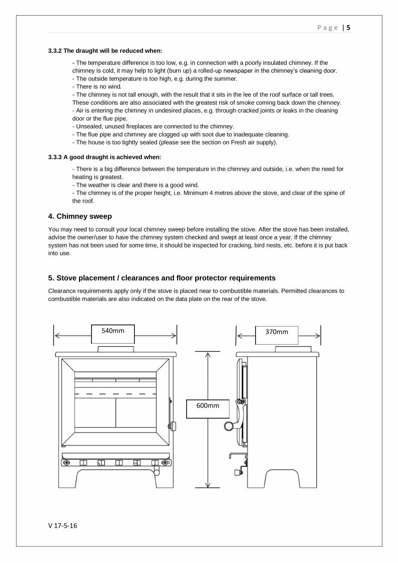
5. Stove placement / clearances and floor protector requirements
Clearance requirements apply only if the stove is placed near to combustible materials. Permitted clearances to
combustible materials are also indicated on the data plate on the rear of the stove.
600mm
540mm 370mm

P a g e | 6
V 17-5-16
5.1 Floor protector requirements
This appliance has been tested as required under ADJ Page 37 Item 2.23a and must be installed onto a
constructional non-combustible hearth 125mm thick.
It is recommended that the appliance be secured to the hearth to ensure stability. There is a hole on the base of
each of the rear legs offering the option to bolt to the floor protector if required.
In situations where the stove is to be fitted into a brick or non-combustible recess, we recommend that the stove
is installed with at least 100mm clearance to the wall, this will allow room air to circulate around the stove; also
the maintenance of the outside stove is easier. When applied to masonry, a layer of wallpaper is normally
classified as a non-combustible surface.
5.2 On the floor
National and Local Building Regulations must again be observed when considering the type, thickness and area
of the hearth to be used in the installation. One should of course always make certain that the underlying floor
surface can bear the weight of the stove.
5.3 Clearance to furniture and soft furnishings
We recommend that the stove be installed 700 mm from furniture. Serious consideration should also be given to
positioning of any furniture that could be adversely affected by heat. The clearances to combustible materials in
front of the stove should be a minimum of 700 mm. When lit, a wood-burning stove gets hot and therefore
adequate protection must be provided, particularly in situations where there is a safety risk to children or the
infirm. A suitable safety guard around the stove should be considered.
6. HETAS amendments
6.1 More detailed advice about existing chimney usage
NOTE: A chimney height of not less than 4.5 metres measured vertically from the outlet of the stove to the top of
the chimney should be satisfactory. Alternatively the calculation procedure given in EN 13384-1 may be used as
the basis for deciding whether a particular chimney design will provide sufficient draught.
The outlet from the chimney should be above the roof of the building in accordance with the provisions of Building
Regulations Approved Document J.
If installation is into an existing chimney then it must be sound and have no cracks or other faults which might
allow fumes into the house. Older properties, especially, may have chimney faults or the cross section may be
too large i.e. more than 230 mm x 230 mm. Remedial action should be taken, if required, seeking expert advice,
if necessary. If it is found necessary to line the chimney then a flue liner suitable for solid fuel must be used in
accordance with Building Regulations Approved Document J.
Any existing chimney must be clear of obstruction and have been swept clean immediately before installation of
the stove. If the stove is fitted in place of an open fire then the chimney should be swept one month after
installation to clear any soot falls which may have occurred due to the difference in combustion between the
stove and the open fire.
A
B C
Non-Combustible
materials (masonry)
A = 100mm
B = 218mm
C = 100mm
Combustible
materials (p/board)
A = 650
B = 868
C = 750
NB Clearances are measured from the edge of the top castings.

P a g e | 7
V 17-5-16
If there is no existing chimney then any new system must be to the designation described above and in
accordance with Building Regulations Approved Document J.
A single wall metal fluepipe is suitable for connecting the stove to the chimney but is not suitable for use as the
complete chimney. The chimney and connecting fluepipe must have a minimum diameter of 150 mm and its
dimension should be not less than the size of the outlet socket of the stove.
Any bend in the chimney or connecting fluepipe should not exceed 45°. 90° bends should not be used.
Combustible material should not be located where the heat dissipating through the walls of fireplaces or flues
could ignite it. Therefore when installing the stove in the presence of combustible materials due account must be
taken of the guidance on the separation of combustible material given in Building Regulations Approved
Document J and also in these stove instructions.
If it is found that there is excessive draught in the chimney then a draught stabiliser should be fitted. Fitting of a
draught stabiliser will affect the requirement for the permanent air supply into the room in which the stove is fitted
in accordance with Approved Document J (see also combustion air supply).
6.2 Commissioning and handover
Ensure all parts are fitted in accordance with the instructions.
On completion of the installation allow a suitable period of time for any fire cement and mortar to dry out, before
lighting the stove. Once the stove is under fire check all seals for soundness and check that the flue is functioning
correctly and that all products of combustion are vented safely to atmosphere via the chimney terminal.
On completion of the installation and commissioning ensure that the operating instructions for the stove are left
with the customer. Ensure to advise the customer on the correct use of the appliance and warn them to use only
the recommended fuel for the stove.
Advise the user what to do should smoke or fumes be emitted from the stove. The customer should be warned to
use a fireguard to BS 8423:2002 (Replaces BS 6539) in the presence of children, aged and/or infirm persons.
6.3 Extractor fan
There must not be an extractor fan fitted in the same room as the stove as this can cause the stove to emit
smoke and fumes into the room.
6.4 Permanent air vent
The stove requires an adequate air supply in order for it to operate safely and efficiently. For most houses an
additional air vent will be required if the stove is rated at over 5kW. Please refer to ADJ 2.3 table 1 for more
information.
In accordance with current Building Regulations the installer may have fitted a permanent air supply vent into the
room in which the stove is installed to provide combustion air. This air vent should not under any circumstances
be shut off or sealed.
6.5 Chimney cleaning
The chimney should be swept at least twice a year. It is important that the flue connection and chimney are swept
prior to lighting up after a prolonged shutdown period.
If the stove is fitted in place of an open fire then the chimney will require sweeping after a month of continuous
operation. This is a precaution to ensure that any “softer” deposits left from the open fire usage have not been
loosened by the higher flue temperatures generated by the closed stove.
6.6 Use of fireguard
When using the stove in situations where children, aged and/or infirm persons are present a fireguard must be
used to prevent accidental contact with the stove. The fireguard should be manufactured in accordance with BS
8423:2002 (Replaces BS 6539).
6.7 Use of operating tools
Always use the operating tools provided when handling parts likely to be hot when the stove is in use.
6.8 CO Alarms

P a g e | 8
V 17-5-16
Building regulations require that whenever a new or replacement fixed solid fuel or wood/biomass appliance is
installed in a dwelling a carbon monoxide alarm must be fitted in the same room as the appliance. Further
guidance on the installation of the carbon monoxide alarm is available in BS EN 50292:2002 and from the alarm
manufacturer’s instructions. Provision of an alarm must not be considered a substitute for either installing the
appliance correctly or ensuring regular servicing and maintenance of the appliance and chimney system.
7. Installing the stove
1. Remove all outer packaging and carefully dispose. 2. Remove top casting and carefully set aside. 3. Carefully lift fire into approximate position on the floor protector. 4. Carefully fit the four baffle bricks (located in wrapping in the fire box) anchoring each upon the
securing pin located on the rear baffle cradle and resting on the air tube toward the front of the fire box (diagram 3 below). It is essential these are fitted or the warranty will be deemed null and void. (See the installation sheet located with the wrapped baffle bricks)
5. Fit top casting on to fire box ensuring a good seal to the rope bed. 6. Accurately position the fire ensuring all necessary safety clearances are adhered to along with the
correct alignment of the flue system to the spigot outlet. 7. Assemble and install flue system accordingly to comply with all national and local regulations. 8. Fit with the screw provided the air control (damper) knob situated under the door to the right (diagram
1 below). The air control knob is the smaller of the two knobs supplied (located in wrapping in the fire box).
9. Fit door knob (diagram 2 below). The door knob is the larger of the two knobs supplied (located in wrapping in the fire box).
10. Commission stove to ensure correct operation and adequate flue draw. 11. Super clean burn features: The design and construction of the Napier stove means it burns at a very
high and intense heat. The 4 way air system ensures complete combustion of the logs resulting in an extremely clean burning process leaving very little, but ash, at the end. The stove owner may experience varying amounts of super fine ash particles that cling to the glass at different cycles of the burn process leaving what appear to be white marks. This ash is the result of your stove working to peak performance. These super fine ash particles cling to the glass because of the temperature difference between the glass surface and the intense heat of the fire. If experienced, it can be removed by simply dusting off with a soft cloth when the stove is off, or has been allowed to cool down.
12. On completion of the installation and commissioning ensure that the operating instructions for the stove are left with the customer. Ensure to advise the customer on the correct use of the appliance and warn them to use only the recommended fuels for the stove.
1 2 Baffle rests on air tube
Baffle rests on
baffle cradle
Baffle
3

P a g e | 9
V 17-5-16
STOVE OPERATION
1. Notes on fuels and general burning.
1. The setting of the air supply, the method of ignition and the lighting intervals depend on the draught
in the chimney, wind and weather conditions, the amount of heat required and the fuel type being
used. This means that it may take some time before you get to know the correct functioning of the
stove under any given circumstances for its optimum operation.
2. Although you can fire your Firenzo stove with almost all types of wood logs, (beech, birch etc.) you
should not burn wet or unseasoned wood. Logs should be stored under a cover for at least 1 year,
though preferably 2 years, and be ventilated to enable drying.
Only Logs with moisture content of 25% or less must be used.
3. Only authorised mineral solid fuels (msf) may be used in UK smoke control areas. A list of which
can be found at www.uksmokecontrolareas.co.uk/fuels.php
4. Petroleum coke fuels and or household waste must not be burnt under any circumstances on this
appliance. Failure to comply will breach the terms of warranty for this appliance
5. The first few times you light the stove, the fire should be moderate so that the heat-resistant paint
can cure before firing more vigorously. During the curing phase, the paint may emit an obnoxious
smell and smoke lightly for the first few times it is lit, which is very normal. Make sure that the room
is well ventilated during this period by opening appropriate doors and windows.
PRIMARY AIRSLIDE
SECONDARY AIRSLIDE
The Primary Airslide controls air
directly into the ember bed and is
the main air control when burning
ancit (msf ).
The Secondary Airslide controls the
airwash curtain over the glass to
keep it clean and is the main air
control when burning wood.
Both Airslides operate by sliding left
for high burn and right for lower
burn.
The Napier stove also has tertiary
and quaternary air supplies that are
fixed and give the stove its
exceptional clean burn ability.

P a g e | 10
V 17-5-16
2. Lighting the stove
1. Firstly open both the primary and secondary air controls to the fully open position, i.e. Slide both
fully to the left and open the door.
Load the stove with your chosen starting fuel, (firelighters, paper etc.) and a small amount of your
chosen fuel, (kindling or ancit) and ignite at base.
Keep door slightly ajar and wait for the fuel to develop strong flames and then gradually start to
build up fuel bed until a good fire is established across the fuel grate. Continue this process until a
glowing ember bed is visible; you can now close the door. You can now also fully close the primary
Airslide control by moving it fully to the right. Do not move the secondary Airslide at this stage.
3. Burning Wood logs
1. Now you have established an ember bed you can begin to refuel using wood logs.
2. The appliance works best with 2 logs, approximately 190 – 210 mm long, loaded front to back.
Under normal modes of operation, this fuel should last about 1 hour. The maximum dimensions of
logs that should be used in the appliance are Length 260mm x Diameter 120mm.
3. Ensure the primary Airslide is fully closed and the secondary Airslide is fully open, open the
door and load in the fuel onto the glowing ember bed, keep the door ajar for 2-3 minutes until the
new fuel has ignited and established strong flames. You can now close the door.
4. If the new fuel fails to ignite open the primary Airslide as well to add extra air until it does ignite and
then reclose the primary Airslide.
5. Once the new logs are ignited and stabilised you can control the desired burn rate of the stove by
adjusting the secondary Airslide down as required to reach a comfortable room temperature.
6. When this fuel load has died back down to a glowing ember bed, begin the reload process as steps
3 – 5 above.
7. Do not run the stove for any extended periods with the primary Airslide open when burning wood
logs, this will cause the stove to over fire and may cause damage to the stove that will not be
covered under warranty.
4. Burning Ancit (MSF)
1. Now you have established an ember bed you can begin to refuel using ancit and / or briquettes.
2. The appliance works best with a load of approx. 1.5 kg of fuel which should last about 1 hour.
3. Ensure the primary Airslide is fully open and the secondary Airslide is fully open, open the
door and load in the fuel onto the glowing ember bed, keep the door ajar for 2-3 minutes until the
new fuel has ignited and established strong flames. You can now close the door.
4. Once the new logs are ignited and stabilised you can control the desired burn rate of the stove by
adjusting the primary Airslide down as required.
5. When this fuel load has died back down to a duller ember bed, begin the reload process as steps
3 – 4 above.
6. Do not use the secondary Airslide to control the burn rate when burning ancit, this air control
supplies the airwash curtain down over the glass and will make the glass blacken and you will lose
the flame picture.

P a g e | 11
V 17-5-16
5. Ash pan removal
1 The ash pan is situated in the base of the fire under the lift up fire grate.
2 Never attempt to remove the ash pan when the fuel is still hot. Empty the ash pan
when the stove is cold the following day.
3 When cold, using the tool provided, engage the lugs at the end of the tool into the catches on the
front of the fire grate and tip the grate up so the remaining ashes drop into the pan and then rest the
grate against the back fire bricks. Disengage the tool.
4 Now put the tool down into the catch at the top front of the ash pan so the lugs again engage into the
catches. You can now lift out the ash pan and safely dispose of the ashes.
5 Before replacing the ash pan ensure any overspill ash is cleaned out from the base of the stove.
Now replace the ash pan by lowering it back in, disengage the tool and then use it to drop the fire
grate back down to its resting position.
6 Never allow the ashes to build up high enough to touch the bottom of the fire grate. It is very
important to keep air flowing under the grate to prevent it from overheating; failure to do this will
damage the grate and this is not covered under warranty.
6. Super clean burn features
1 The design and construction of the Napier stove means it burns at a very high and intense heat.
The 4 way air system ensures complete combustion of the fuel resulting in an extremely clean
burning process leaving very little, but fine ash, at the end.
You may experience varying amounts of super fine ash particles that may cling to the glass at
different cycles of the burn process leaving what appear to be white marks. This fine ash is the
result of your stove working to peak performance. These super fine ash particles cling to the glass
because of the temperature difference between the glass surface and the intense heat of the fire
If experienced, it can easily be removed by simply dusting off with a soft cloth when the stove is off,
or has been allowed to cool down.
7. Defra Notifications
7.1 The Clean Air Act 1993 and smoke control areas
Under the Clean Air Act local authorities may declare the whole or part of the district of the authority to be a smoke control area. It is an offence to emit smoke from a chimney of a building, from a furnace or from any fixed boiler if located in a designated smoke control area. It is also an offence to acquire an "unauthorised fuel" for use within a smoke control area unless it is used in an "exempt" appliance ("exempted" from the controls which generally apply in the smoke control area).
The Secretary of State for Environment, Food and Rural Affairs has powers under the Act to authorise smokeless fuels or exempt appliances for use in smoke control areas in England. In Scotland and Wales this power rests with Ministers in the devolved administrations for those countries. Separate legislation, the Clean Air (Northern Ireland) Order 1981, applies in Northern Ireland. Therefore it is a requirement that fuels burnt or obtained for use in smoke control areas have been "authorised" in Regulations and that appliances used to burn solid fuel in those areas (other than "authorised" fuels) have been exempted by an Order made and signed by the Secretary of State or Minister in the devolved administrations.
Further information on the requirements of the Clean Air Act can be found at: http://smokecontrol.defra.gov.uk/
Your local authority is responsible for implementing the Clean Air Act 1993 including designation and supervision of smoke control areas and you can contact them for details of Clean Air Act requirements

P a g e | 12
V 17-5-16
7.2 Refuelling on to a low fire bed
If there is insufficient burning material in the fire bed to light a new fuel charge, excessive smoke emission can occur. Refuelling must be carried out onto a sufficient quantity of glowing embers and ash that the new fuel charge will ignite in a reasonable period. If there are too few embers in the fire bed, add suitable kindling to prevent excessive smoke
7.3 Fuel overloading
The optimum amount of fuel as specified in section (operation 3.2 or 4.2) should not be exceeded, overloading can cause excess smoke.
7.4 Operation with door left open
Operation with the door open can cause excess smoke. The appliance must not be operated with the appliance door left open except as directed in the instructions.
7.5 Dampers left open
Operation with the air controls or appliance dampers open can cause excess smoke. The appliance must not be operated with air controls, appliance dampers or door left open except as directed in the instructions.
7.6 Disposal of Ash
Ash as it is removed from the stove must be placed into a metal container with a tight fitting lid and set aside onto a non-combustible floor until all cinders have cooled. It can then be disposed by burial or other means.
8. Hetas Notifications
8.1 More detailed advice about existing chimney usage
NOTE: A chimney height of not less than 4.5 metres measured vertically from the outlet of the stove to the top of the chimney should be satisfactory. Alternatively the calculation procedure given in EN 13384-1 may be used as the basis for deciding whether a particular chimney design will provide sufficient draught.
The outlet from the chimney should be above the roof of the building in accordance with the provisions of Building Regulations Approved Document J.
If installation is into an existing chimney then it must be sound and have no cracks or other faults which might allow fumes into the house. Older properties, especially, may have chimney faults or the cross section may be too large i.e. more than 230 mm x 230 mm. Remedial action should be taken, if required, seeking expert advice, if necessary. If it is found necessary to line the chimney then a flue liner suitable for solid fuel must be used in accordance with Building Regulations Approved Document J.
Any existing chimney must be clear of obstruction and have been swept clean immediately before installation of the stove. If the stove is fitted in place of an open fire then the chimney should be swept one month after installation to clear any soot falls which may have occurred due to the difference in combustion between the stove and the open fire.
If there is no existing chimney then any new system must be to the designation described above and in accordance with Building Regulations Approved Document J.
A single wall metal fluepipe is suitable for connecting the stove to the chimney but is not suitable for use as the complete chimney. The chimney and connecting fluepipe must have a minimum diameter of 150 mm and its dimension should be not less than the size of the outlet socket of the stove.
Any bend in the chimney or connecting fluepipe should not exceed 45°. 90° bends should not be used.
Combustible material should not be located where the heat dissipating through the walls of fireplaces or flues could ignite it. Therefore when installing the stove in the presence of combustible materials due account must be taken of the guidance on the separation of combustible material given in Building Regulations Approved Document J and also in these stove instructions.
If it is found that there is excessive draught in the chimney then a draught stabiliser should be fitted. Fitting of a draught stabiliser will affect the requirement for the permanent air supply into the room in which the stove is fitted in accordance with Approved Document J (see also combustion air supply).

P a g e | 13
V 17-5-16
8.2 Commissioning and handover
On completion of the installation and commissioning ensure that the operating instructions for the stove are left with you, the home owner or stove user, by the installer. Ensure you are advised on the correct use of the appliance and that you understand to use only the recommended fuel for the stove.
8.3 Warning note on fume emission
Properly installed, operated and maintained this stove will not emit fumes into the dwelling. Occasional fumes from de-ashing and re-fuelling may occur. However, persistent fume emission is potentially dangerous and must not be tolerated. If fume emission does persist, then the following immediate action should be taken:-
(a) Open doors and windows to ventilate the room and then leave the premises.
(b) Let the fire go out.
(c) Check for flue or chimney blockage and clean if required
(d) Do not attempt to relight the fire until the cause of the fume emission has been identified and corrected. If necessary seek expert advice.
The most common cause of fume emission is flue or chimney blockage. For your own safety the stove and flue system must be kept clean at all times.
CO Alarm
Your installer should have fitted a CO alarm in the same room as the appliance. If the alarm sounds unexpectedly, follow the instructions given under “Warning Note” above.
8.4 Extractor fan
There must not be an extractor fan fitted in the same room as the stove as this can cause the stove to emit smoke and fumes into the room.
8.5 Permanent air vent
As this stove is rated under 5.0kW a permanent air vent will not normally be required for it to operate safely and efficiently.
In accordance with current Building Regulations the installer may have fitted a permanent air supply vent into the room in which the stove is installed to provide combustion air. This air vent should not under any circumstances be shut off or sealed.
8.6 Chimney cleaning
The chimney should be swept at least twice a year. It is important that the flue connection and chimney are swept prior to lighting up after a prolonged shutdown period.
If the stove is fitted in place of an open fire then the chimney will require sweeping after a month of continuous operation. This is a precaution to ensure that any “softer” deposits left from the open fire usage have not been loosened by the higher flue temperatures generated by the closed stove.
8.7 Periods of prolonged non-use
If the stove is to be left unused for a prolonged period of time then it should be given a thorough clean to remove ash and unburned fuel residues. To enable a good flow of air through the appliance to reduce condensation and subsequent damage, leave the air controls fully open.
8.8 Use of fireguard
When using the stove in situations where children, aged and/or infirm persons are present a fireguard must be used to prevent accidental contact with the stove. The fireguard should be manufactured in accordance with BS 8423:2002 (Replaces BS 6539).
8.9 Aerosol sprays
Do not use an aerosol spray on or near the stove when it is alight.

P a g e | 14
V 17-5-16
Maintenance
9. Routine stove maintenance Only genuine Firenzo spares may be used in the stove. Failure will void the warranty. Contact your retailer to obtain any necessary spare parts.
9.1 Cast iron surfaces
Each cast iron component is individually poured and cast. There are no two pieces that are identical. This is partly due to the tolerances of the casting process, partly because the stoves are a work of craftsmanship.
The cast surfaces of the stove are painted with high temperature Stovebright paint. It is best maintained by simply vacuuming it with a soft brush attachment or wiping it down with a dry, dust-free cloth when cool.
If the stove is used too vigorously, the painted surface may assume a greyish tinge over time, but the stove can easily be freshened up with high temperature Stovebright paint.
9.2 Painted Surfaces
Painted surfaces are coated with Stovebright high temperature paint. To clean use a clean dry cloth. Do not use abrasive cleaners/materials that may cause scratching to the surface.
9.3 Glass window
If the stove is used correctly, very little or no soot will be deposited on the ceramic glass window. If soot does form on the glass as the stove is being lit, it will burn away once normal combustion begins in the stove. If the glass window becomes thoroughly covered in soot due to incorrect operation, the soot can be easily removed using an approved glass cleaner. The glass must be cold when you clean it. Avoid stoking the stove with pieces of wood that are so long that they press against the glass window when the door is closed and crack the glass.
9.4 Ceramic glass replacement
Only replace with genuine Firenzo Schott Robax™ glass.
9.2.4 Refractory linings
Only replace with genuine Firenzo parts. The base of the fire uses our special Firenzo refractory kiln bricks. The sides, back and baffle of the fire uses Firenzo Skamolex™ bricks. The condition of the refractory linings needs to be checked annually by your chimney sweep and replaced if signs of deterioration are evident.
9.2.5 Air supply components
Only replace with genuine Firenzo parts. Air supply components are made from steel and/or high temperature bearing stainless steel and need to be checked annually by your chimney sweep and replaced if signs of deterioration are evident.
9.2.6 Gaskets
Only replace with genuine Firenzo parts.
Over time, the gaskets and seals around the stove will wear and should be replaced as needed in order to prevent air leaks resulting in uncontrolled combustion.
9.2.7 General
Reasons for overly rapid wear of internal parts
- Stove fired too vigorously (see section 5.6) - Use of very corrosive fuel. Eg petroleum coke or treated timber. - Too much soot on top of the baffles (please see the section on Cleaning). - Too much ash in the ash pan (please see the section 5).

P a g e | 15
V 17-5-16
9.3 Cleaning the stove/chimney
It is important that the stove is regularly maintained by a competent engineer and that the whole system (stove, flue connector and flue) are cleaned regularly.
In particular on the topside of the baffle bricks, layers of ashes and soot will form as a result of the chimney draft and after a sweep.
The baffle bricks can be removed from the stove to assist with cleaning the flue and firebox.
Removing the baffle bricks:
Only remove the baffle bricks when the stove is cold.
Push the middle two baffle bricks up and slide them left and right over the corresponding bricks. This will leave an opening big enough for the chimney brush to pass between the other two bricks. Take care when lifting them from the anchoring pin. To remove the bricks from the stove turn the moved baffle bricks sideways (east/west) and tip them up, and slide down through the space it created. Lift, twist and then also remove the two outer bricks.
When the baffle bricks are removed, there is access to clean the flue chamber above the baffle bricks. Each of the four baffle bricks are held in place by an upright pin positioned on the baffle cradle at the back of the inside of the fire box.
Clean the baffle bricks before replacing, and take care that they are properly put in place ensuring they are placed onto the retaining pins on the rear baffle cradle and resting on the air tube toward the front of the fire box.
The chimney sweep must remove the soot in the stove, in addition to sweeping the chimney and cleaning the flue pipe. The number of annual sweepings/cleanings of the stove should be determined in consultation with your chimney sweep.
Warranty Details
Firenzo stoves are manufactured in New Zealand, using the highest quality materials, workmanship and
the latest manufacturing techniques, which is why a full 10 year firebox warranty and 1 year parts
warranty is offered. (UK consumer laws apply)
Firenzo Woodfires UK Ltd warrants the steel firebox, cast iron top and door against defective materials
and workmanship only which would render it unfit for normal domestic use, from the date of purchase by
the original consumer, for a period of 10 years.
All other associated components including, seals, glass, refractory linings, grates and air supply items
etc. are warranted for a period of 1 year from the date of original purchase for domestic use against
defective materials and workmanship only.
The Firenzo stove must be installed strictly in accordance with the building code and / or Hetas
guidelines.
The Firenzo stove must be operated and maintained strictly in accordance with terms of the installation
and operation manual.
This warranty covers appliance and or components like for like replacement or repair at Firenzo Fires
UK ltd sole discretion and must be approved prior to any work being undertaken.
A claim under this warranty should be directed to the retailer who supplied the Firenzo stove. If this is
not possible, write directly to Firenzo Fires UK Ltd, stating details of fault, serial number of your stove,
date and proof of purchase and name of retailer where the Firenzo stove was purchased.

P a g e | 16
V 17-5-16
This is an important manual;
It must be read and kept safe for
future reference.
Installer Details
Name & contact
……………………………………………………………………………………
……………………………………………………………………………………………
……………………………………………………………………………………………
……………………………………………………………………………………………
……………………………………………………………………………………………
Retailer details
Name & Contact
……………………………………………………………………………………
……………………………………………………………………………………………
……………………………………………………………………………………………
……………………………………………………………………………………………
……………………………………………………………………………………………
Appliance serial #
…………………………………………………………………………………………