final technical report prototype 20 watt solid-state
TRANSCRIPT
D 5-1 3 4 2 4
F I N A L T E C H N I C A L R E P O R T P R O T O T Y P E 20 W A T T
S O L I D - S T A T E T E L E M E T R Y T R A N S M I T T E R
- VOLUME I OF 1 1 1 -
Apr i l 1, 1968
(THRU)
COMPANV - SPACE DlVlSlON
i '
F I N A L TECHNICAL REPORT - PROTOTYPE 20 WATT, SOLID-STATE TELEMETRY TRANSMITTER
M AS 8 - 2 0 7 7 7 MODEL NO. CONTRACT NO.
PPEPARED R Y : !J. LEDREW AND J . DETTF1ANN TEL E"ETRY SYSTEPS
A P R I L 1, 1968
W. B. SMITH
DOCUMENT NO. D5-13424 VOLUI4E I OF I11
ISSUE NO. ISSUED TO
T H E &n%/Nc C O M P A N Y S P A C E D I V I S I O N L A U N C H S Y S T E M S B R A N C H
.
.
D5-13424
REV IS IONS
DESCR I PT ION 0 ATE
ii

D5-13424
ABSTRACT A N D LIST OF KEY WOPDS
This document cons t i tu tes t h e technical report for a 20 Watt Sol id-s ta te Telemetry Transmitter developed under Contract NAS8-20777 f o r the National Aeronautics a n d Space Administration, G . C . Marshall Space Flight Center. The document i s organized as follows:
Volume I Summary Technical Report Volume I1 Test Procedures a n d Results Volume I11 Operating and Maintenance Instruct ions
Transmitter Solid State S-Band Varactor Frequency Mu1 t ip1 i e r Power Amp1 i f i e r Voltage-Controlled Osc i l la tor ( V C O ) S t r i p Line Crystal -Control led Osci 11 a t o r Exciter Modulator Frequency Modul a t i on (FM)
i i i
D5-13424
CONTENTS
PA RAG RAP H
REV1 S I ONS ABSTRACT AND LIST OF KEY WORDS CONTENTS ILLUSTRATIONS AND TABLES
VOLUME I OF I11
SECTION 1 - INTRODUCTION
SECTIO?! 2 - TEST RESULTS - SUMMARY
SECTION 3 - CONCLUSIONS AND RECOMMENDATIONS
PAGE
ii iii i v V
1-1
2-1
3-1
i v

D5-13424
ILLUSTRATIONS
FIGURE
2-1 T r a n s m i t t e r C h a r a c t e r i s t i c s 2-2 T r a n s m i t t e r Warm-up C h a r a c t e r i s t i c s 2-3 AC I n v u t Inmedance 2-4 2-5 Modulat ion Frequency Response 2-6 Automat ic Level Cont ro l Performance
500 KHz Devi a t i on L i n e a r i t y
TABLES
TABLE
2-1 Tes t Data 2-11 T e s t Equipment
PAGE
2-3 2-4 2-5 2-6 2-7 2-9
PAGE
2-1 1 2-21
V

D5-13424
SECTION 1
INTRODUCTION
1.0 GENERAL
Th is volume of Document D5-13424 conta ins a d e l i n e a t i o n i n summary form o f the design goa ls and requirements f o r t h e development o f a p r o t o t y p e 20-watt, s o l i d - s t a t e , u l t r a h i g h f recuency t e l e m e t r y t r a n s m i t t e r . Th is e f f o r t was accomPlished f o r t h e George C. Marsha l l %ace F l i g h t Center under NASA Cont rac t NAS8-20777.
The r e s u l t s o f t h e t e s t program a r e summarized i n t h e fo rm o f graphs and p l o t s i n Sec t ion 2 . Several conc lus ions and recommendations based upon t h e r e s u l t s o f t h e design e f f o r t and t h e t e s t Program are g i v e n i n Sec t ion 3.
1 . 1' DES I GN GOALS AND REQU I REMENTS
The design o f t h e t r a n s m i t t e r i s based w o n NASA/MSFC s n e c i f i c a t i o n 110158. a r e l i s t e d below:
The performance and p r o d u c t c h a r a c t e r i s t i c s f o r t h e t r a n s m i t t e r
1.1.1 E l e c t r i c a l
1.1.2 Prime Power Source
The t r a n s m i t t e r s h a l l be capable o f meet ing a1 1 t h e performance r e q u i r e - ments s p e c i f i e d h e r e i n when energ ized by a pr ime power source o f 28 - + 4 Vdc, w i t h an impedance n o t g r e a t e r than 1 ohm.
1.1.3 Warm-up Time
The t r a n s m i t t e r s h a l l meet a1 1 t h e requirements o f t h i s speci f i c h t i o n w i t h i n 3 minutes a f t e r power has been app l ied .
1.1.4 E f f i c i e n c y
The o v e r a l l dc t o RF conversion e f f i c i e n c y s h a l l be a t l e a s t 10 p e r c e n t w i t h no more than 8 amps t o t a l c u r r e n t .
1.1.5 Output Frequency
The t r a n s m i t t e r s h a l l p rov ide an o u t p u t f requency o f 2277.500000 MHz.
1.1.6
V a r i a t i o n i n t h e t r a n s m i t t e r c a r r i e r f requency s h a l l n o t exceed p l u s o r minus 0.005 p e r c e n t o f t h e assigned c a r r i e r f requency.
Frequency S t a b i 1 i ty
1-1

D5-13424
1.1.7 Output Power
The minimum o u t n u t power o f the t r a n s m i t t e r s h a l l be 20 w a t t s when t h e t r a n s m i t t e r i s te rmina ted i n t o a than 1.8 a t any phase angle.
nominal 50-ohm l o a d hav ing a VSWR l e s s
1.1.8 Modulat ion I n p u t Impedance
The modu la t ion i n p u t impedance o f t h e t r a n s m i t t e r s h a l l be 1QDOO ohms o r g r e a t e r over t h e frequency range o f 0 t o 200 KHz.
1.1.9 Modul a t i on D i s t o r t i o n
When t h e t r a n s m i t t e r i s modulated w i t h a peak d e v i a t i o n o f 125 KHz, i t s demodulated o u t o u t s h a l l c o n t a i n second and t h i r d harmonics o f t h e modu- l a t i o n f requency which a r e r e s p e c t i v e l y 35 db and 45 db, o r g r e a t e r , be- low t h e o u t n u t l e v e l o f t h e correspondina modu la t ion f requency f rom 300 Hz t o 100 KHz.
1.1.10 I n t e r m o d u l a t i o n D i s t o r t i o n
When t h e t r a n s m i t t e r i s modulated by two s u b c a r r i e r s o f equal ampl i tude and s p e c i f i e d f requenc ies , the t r a n s m i t t e r demodulated o u t p u t sum and d i f fe rence s u b c a r r i e r f requencies s h a l l be 40 db o r g r e a t e r , below each s u b c a r r i e r 1 eve1 . 1.1.11 Devi a t i o n S e n s i t i v i t y
The d e v i a t i o n s e n s i t i v i t y o f t h e t r a n s m i t t e r s h a l l be 200 + 10 KHz p e r v o l t rms o r 1.414 v o l t s peak. l a t i o n s i g n a l s h a l l produce an i n c r e a s e i n c a r r i e r f requency. A n e g a t i v e v o l t a g e excurs ion o f t h e modulat ion s i g n a l s h a l l produce a decrease i n c a r r i e r f req uency .
A p o s i t i v e v o l t a g e e x c u r s i o n of t h e modu-
1 . 1 . 1 2 Devi a t i on L i nea ri ty
The AC d e v i a t i o n l i n e a r i t y o f t h e t r a n s m i t t e r s h a l l be w i t h i n p l u s o r minus one p e r c e n t o f t h e best s t r a i g h t l i n e approx imat ion f o r 125 KHz peak d e v i a t i o n and w i t h i n p lus o r minus two p e r c e n t f o r 500 KHz peak de- v i a t i o n a t modu la t ion f requencies f rom 0 t o 100 KHz.
1.1.13 C a r r i e r D e v i a t i o n
The t r a n s m i t t e r s h a l l be capable o f be ing d e v i a t e d f rom c a r r i e r f r e - quency a t l e a s t p l u s and minus 500 KHz.
1.1.14 Frequency Response
The t r a n c m i t t e r frequency response s h a l l be f l a t w i t h i n p l u s o r minus 1.5 db w i t h r e s p e c t t o 50 KHz modula t ion t requency, a t moduidt iu i i f i -e- quencies from zero t o 500 KHz.
1-2
D5-13424
1.1.15 Incidental Frequency Modulation
I -
The t ransmi t te r incidental frequency modulation shall not be grea te r than 8 KHz peak-to-peak.
1.1.16 Incidental Amplitude Modulation
The t ransmi t te r incidental amplitude modulation shal l not be grea te r than 5 Vercent.
1.1.17 Open Ci rcui t , Short C i rcui t Protection
The t ransmi t te r shall n o t be damaged nor shall i t s performance be im- paired when subjected t o open c i r c u i t a n d short c i r c u i t conditions on the output f o r a period of 15 minutes.
1.1.18 Rel iab i l i ty
The t ransmi t te r shall have a minimum mean time between f a i l u r e of 10,000 hours and be capable of cyclic operation with a minimum of 330 20-minute cycles , 10 minutes "on" and 10 minutes "of f" . The t ransmit ter shal l have a minimum mean l i f e of 3000 hours.
1.1.19 Polar i ty Reversal
Reversal of the 28.0 VDC i n p u t power source leads shall not damage the t ransmit ter .
1.1.20 Modulation Overload Protection
The t ransmi t te r shal l not be damaged nor i t s performance degraded a f t e r - t 28.0 VDC i s applied t o the modulation i n p u t .
1.2 ENVIRONMENTAL
1.2.1 Thermal Shock
The t ransmi t te r shal l not be damaged nor shall i t s Derformance be i m - paired by exposure t o abrupt temperature changes of minus 20" t o plus 75°C w i t h i n a period of n o t l e s s than 2 .5 nor more than 4.0 minutes and plus 75°C t o minus 20°C i n the same time in te rva l .
1.2.2 Temperature Cycl ing
The t ransmi t te r sha l l no t be damaged nor shal l i t s performance be i m - paired by exposure t o gradually applied temperatures from m i n u s 20°C t o plus 75°C.
1-3
D5-13424
1 .2 .3 Moisture Resistance
The t ransmi t te r shall n o t be damaged n o r shal l i t s Derformance be i m - paired by exposure t o a re la t ive humidity of 95 percent with tempera- tures from minus 20°C t o plus 70°C.
1.2.4 Acceleration
The t ransmi t te r shall n o t be damaged nor shall i t s performance be im- Paired when subjected t o an acceleration o f 50 g .
1 .2 .5 Alti tude
The t ransmi t te r shal l n o t be damaged nor shal l i t s oerformanc be i m - paired when subjected t o a reduced barometric pressure o f lo-$ mr;l c f mercury . 1.2.6 Shock
The t ransmi t te r shal l n o t be damaged nor s h a l l i t s performance be i m - paired when subjected t o a half sine wave shock acceleration o f 50 g fo r 11 p l u s or minus 1 msec.
1.2.7 Vibration
1.2.7.1 Sine Wave
The t ransmi t te r sha l l not be damaged nor shal l i t s performance be i m - paired when subjected t o vibrations from 10 t o 2,000 Hz a t 20 g peak amp1 i tude.
1.2.7.2 Random Motion
The t ransmi t te r sha l l not be damaged nor sha l l i t s performance be i m - paired when subjected t o random motion of 20 g rms f o r 5 minutes.
1.2.8 Radio Frequency Interference
The t ransmi t te r sha l l not generate nor be suscept ible t o RF1 when t e s t e d in accordance w i t h the applicable paragraphs of SFecification MIL-I-6181D.
1 .2 .9 Thermal Vacuum
The t ransmi t te r sha l l neither be damaged nor shal l i t s performance be im- paired when subjected t o the conditions of 5.2.7 of 50M71810.
1.2.10 Acoustical Noise
The t ransmi t te r shal l nei ther be damaged nor shal l i t s performance be impaired when subjected t o the conditions o f 5.2.4 of 5 G Z ; E C . In addition t o the above e lec t r ica l and environmental requirements , the allowable maximum weight of the t ransmi t te r i s s e t a t 12 pounds.
1-4
D5 - 1 3424
SECTION 2
TEST RESULTS - SUMMARY
2 . 0 , GENERAL
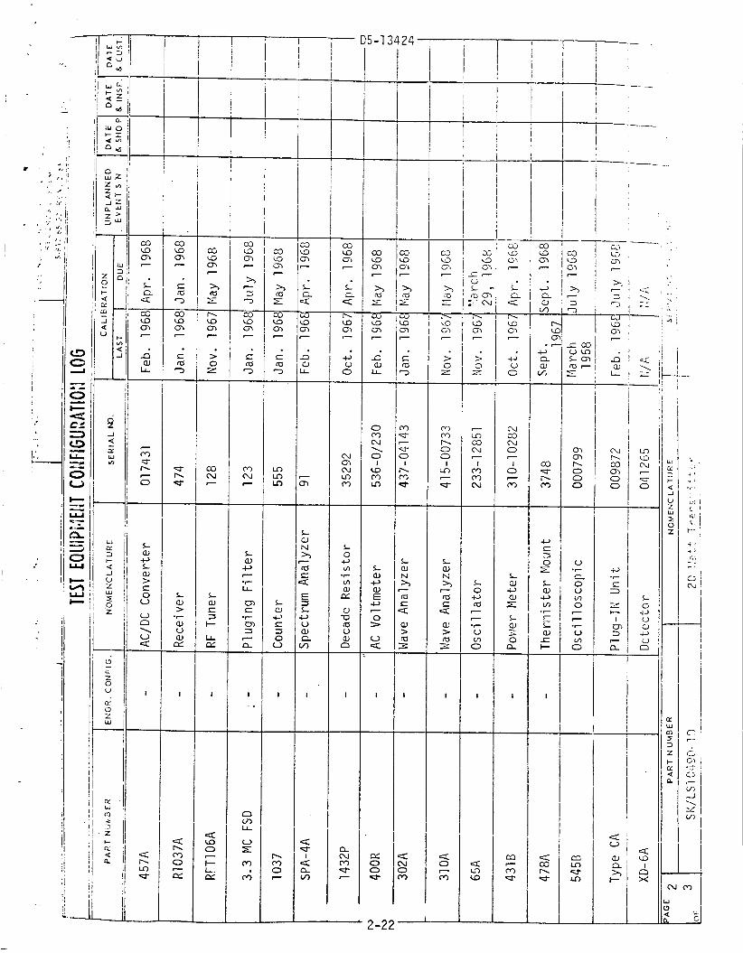
T h i s s e c t i o n conta ins t h e summary o f t h e r e s u l t s o b t a i n e d f r o m t h e t e s t program s p e c i f i e d i n Volume 11, Sec t ion 1 o f t h i s document. The o r i g i n a l data sheets and t e s t eouinment l i s t a r e conta ined i n S e c t i o n 2 o f Vo l - I 1 and were tyned f o r t h i s s e c t i o n f o r convenience.
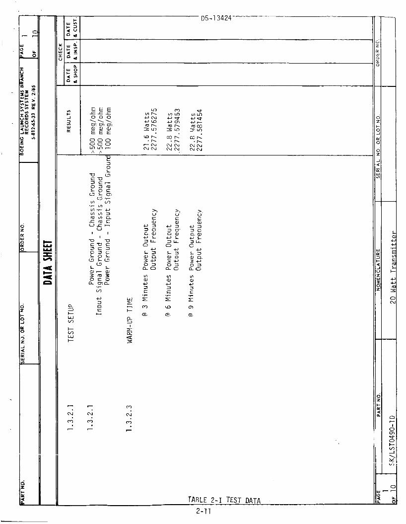
The t e s t program as s p e c i f i e d i n Volume I 1 was n o t performed i n i t s en- t i r e t y . The a c t u a l t e s t s moni tored by Boeing Q u a l i t y Cont ro l were l i m i t e d t o those t e s t s conta ined i n paragraphs 1.3.2.1 ( a ) and ( b ) th rough 1.3.2.12. I n f o r m a l t e s t s , w i t h o u t Q u a l i t y Contro l observa t ion , were con- ducted f o r pressure leakage, automat ic l e v e l c o n t r o l Derformance and RFI l i n e conducted, audio f reauency s u s c e n t i b i l i t y .
The environmental t e s t s were not conducted. The base temperature o f the t r a n s m i t t e r was main ta ined a t approx imate ly 22-5°C f o r a1 1 t e s t s .
I n general , t h e t r a n s m i t t e r met t h e requirements o f a l l t h e t e s t s con- ducted w i t h t h e exceDtion o f power o u t p u t f o r a supply v o l t a g e o f 24 v o l t s , dc t o RF e f f i c i e n c y a t a supply v o l t a g e o f 32 v o l t s , and t h e R F I audio suscept i b i 1 i ty t e s t .
Because o f t h e l a r g e drop i n power o u t t w t a t a suDply v o l t a g e s e t t i n g o f 24 v o l t s , a l l t e s t s were conducted w i t h a minimum supp ly v o l t a g e o f 25.5 v o l t s .
2.1 Tes t Summary
The f o l l o w i n g i s a b r i e f d iscuss ion and summary o f t h e r e s u l t s o b t a i n e d f rom t h e t e s t s which were conducted. r e f e r t o t h e da ta sheets and t h e paragraph o f t h e t e s t procedure o f Volume 11.
The re fe renced paragraph numbers
2.1.1 Ground I s o l a t i o n (Test Paragranh 1.3.2.1.B)
The i s o l a t i o n between grounds was 100 megohms o r more. ment was f o r a t l e a s t 10 megaohms.
2.1.2 P r e s s u r i z a t i o n (Test Paragraph 1.3.2.1.C)
The r e q u i r e -
The u n i t was p r e s s u r i z e d f o r a 24 hour per iod . 21.10 ps ig, and a t t h e end o f t h e t e s t i t had dropped t o 20.54 p s i g . Th is t e s t was conducted by eng ineer ing and was n o t m o n i t o r e d by q u a l i t y c o n t r o l .
The i n i t i a l p ressure was
2-1
D5- 1 3424
2.1.3 Output Power, Frequency S t a b i l i t y , and DC-RF E f f i c i e n c y ( T e s t Paraqraph 1.3.2.2)
Current, frequency, power ou tpu t and e f f i c i e n c y were a l l w i t h i n r e a u i r e - ments f o r t h i s t e s t except w i t h a 32 v o l t suco ly i n p u t t h e e f f i c i e n c y dropped below t h e 10% requirement t o 8.95% and w i t h a 25 v o l t supply i n - p u t e f f i c i e n c y was 9.22% and t h e o u t n u t Dower 16.8 w a t t s (20 w a t t s r e - q u i r e d ) .
2.1.4
The t e s t data i s shown i n F i g u r e 2-1.
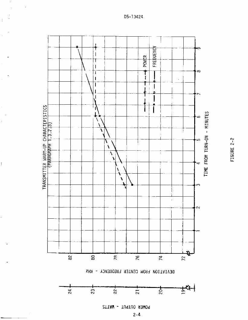
Warm-up Time ( T e s t ParagraPh 1.3.2.3)
The t ransmi t t e r s a t i s f i e d t h i s t e s t r e q u i rement. f o r a 12 hour p e r i o d and had a base temperature o f approx imate ly 16°C a t t h e s t a r t o f t h e t e s t . The data i s shown i n F i g u r e 2-2.
The u n i t was denergi zed
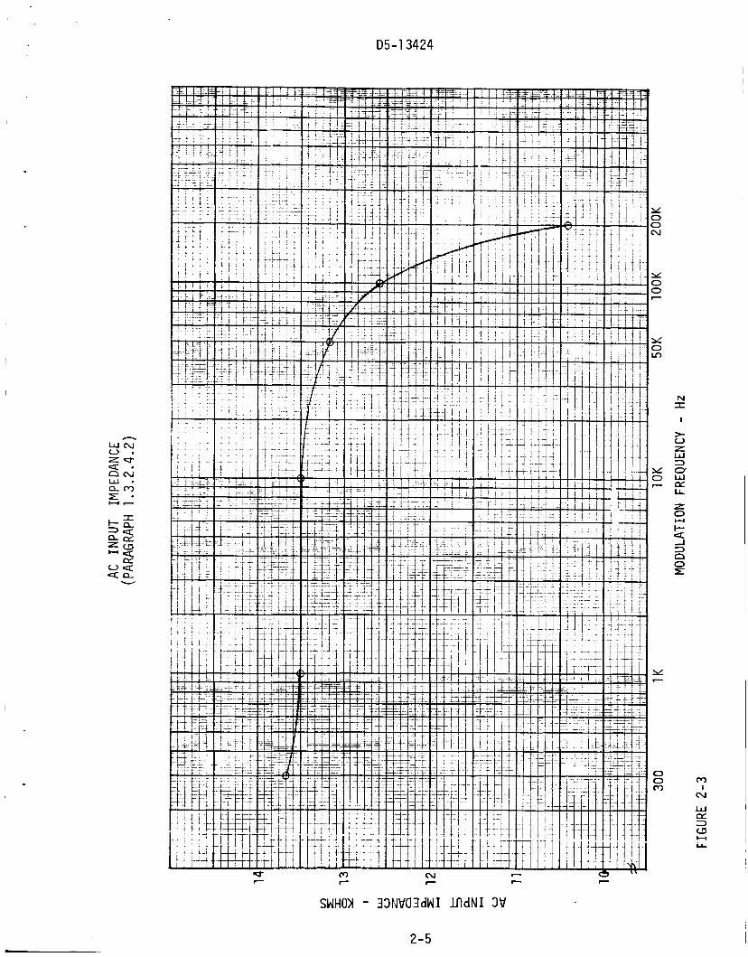
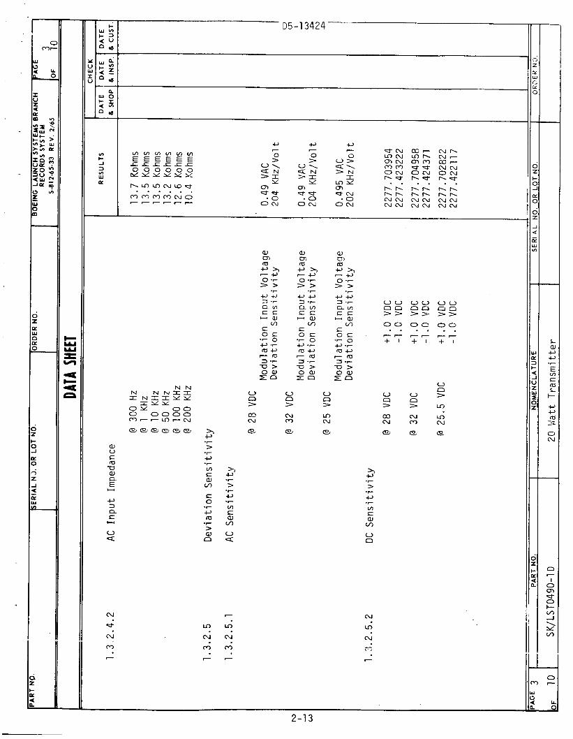
2.1.5 I n p u t ImPedance (Test Paragraph 1.3.2.4)
The modu la t ion i n p u t impedance was w i t h i n requi rements (10,000 ohms o r g r e a t e r ) f rom dc t o 200 KHz. The AC i n p u t impedance data i s shown i n F igure 2-3.
2.1.6 D e v i a t i o n S e n s i t i v i t y (Tes t Paragraph 1.3.2.5)
Both t h e ac and dc d e v i a t i o n s e n s i t i v i t y were w i t h i n t h e requirements o f 200 + 10 KHz p e r 1 v o l t rms o r 1.414 v o l t peak. caused a n i n c r e a s e i n frequency and a n e g a t i v e v o l t a g e caused a decrease i n f requency.
A p o s i t i v e v o l t a g e
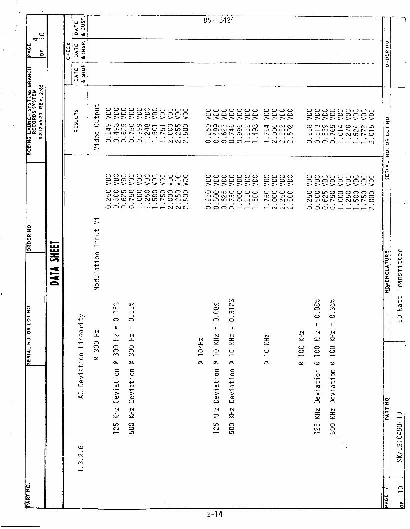
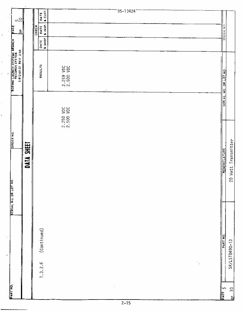
2.1.7 D e v i a t i o n L i n e a r i t y (Tes t Paragraph 1.3.2.6)
The d e v i a t i o n l i n e a r i t y was w e l l w i t h i n requi rements f o r bo th t h e 125 KHz and 500 KHz d e v i a t i o n s .
2.1.8
The t e s t r e s u l t s a r e shown i n F i g u r e 2-4.
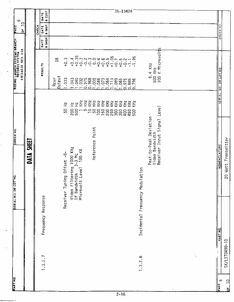
Frequency Response (Tes t Paragraph 1.3.2.7)
The frequency response o f the u n i t was w i t h i n requi rements (+ 1.5 db) t o 470 KHz (500 KHz requ i red) . The t e s t da ta a r e shown i n FTgure 2-5. T h i s da ta has n o t been c o r r e c t e d o r compensated f o r t e s t system response, i . e . da ta i n c l u d e s r e c e i v e r and meter f requency response and thus may be b e t t e r than t h a t shown. Tests e a r l i e r i n t h e week i n d i c a t e d t h e r e - sponse a t 500 KHz would be i n t h e o r d e r o f 0.5-1.0 db down.
2.1.9 I n c i d e n t a l Frequency Modulat ion ( T e s t Paragraph 1.3.2.8)
The t r a n s m i t t e r i n c i d e n t a l FM was measured t o be 6.4 KHz i n c l u d i n g r e - c e i v e r n o i s e and i n c i d e n t a l FM. The measurement technique l e d e l i m i n a t e d r i p p l e s i g n a l s i n h e r e n t i n t h e r e c e i v e r ou tpu t . i n c l u d e any e n v i ronrnental e f f e c t s .
The above da ta d i d n o t
2-2

D5-13424
SllWM - ’d3MOd Ad
D5- 1 3424
N co
s i i w m - i n d i n o W M O ~
2-4
cu I
N
h
D5-13424
m I
cu I
r c c
SWHOI - 33NWCDdWI l f ldNI 3W
2-5

D5-13424
1 I N I Y
V
-0
CCI
N I 0 0 Cr)
-_ - r
0 m N
m (u
(u
0
cu
m h
F
0 m 7
m N
7
0 ?
n \
3 n
n N
\ b
v,
0 > I
I- 3
5
a 5 0 E W > W V W E
U
d I cu w CL: =3
LL E
SllOA - llldNI NOIlWlflQOW
2-6

D5-13424 Y 0 0 LD
Y 0 0 - x 0 LD
c; - I
N I
2-7
D5 - 1 3424
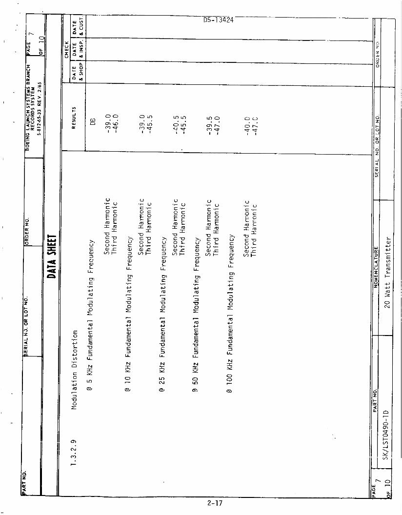
2.1.10 Modulation Distcrtion (Test P a r a g r a p h 1 .3 .2 .9)
Test data shows the unit s a t i s f i e d the requirements, however, t h i s d a t a does include the frequency source, and receiver d i s t o r t i o n .
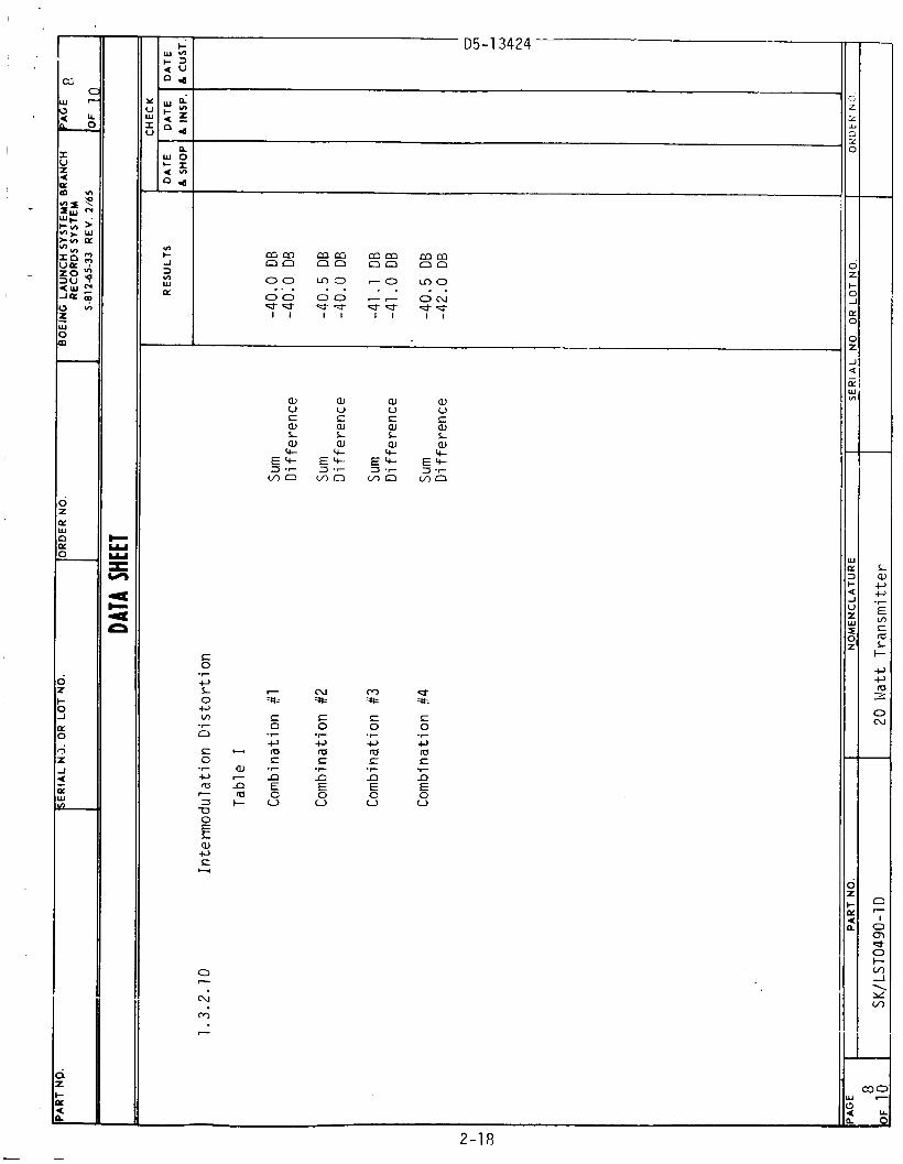
2 . 1 . 1 1 Intermodulation Distortion (Test Paraaraph 1.3.2.10)
Test d a t a shows the u n i t s a t i s f i e d the renuirements, however, d a t a a l so i ncl udes t e s t enui ?men t d i s tort i on.
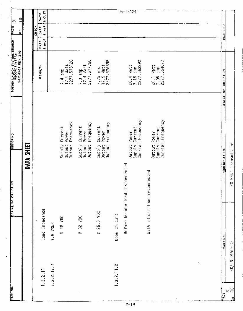
2 . 1 . 1 2 Load Im?edance
2.1.12.1 VSWR (Test Paragraph 1.3.2.11.1)
During t h i s t e s t freouency and s u w l y i n r u t current remained within reauire- ments, however, the output oower dropped below the recuired 20 watts a t 28 V (17.9 w a t t ) , 32 V (17.4 wat t ) and 25.5 V ( 1 7 . 9 wat t ) .
2.1.12.2 Open Circui t (Test Paragraph 1.3.2.11.2)
The units performance was essent ia l ly unchanged by th i s t e s t . o u t p u t , supply current a n d frequency were within reaui rement both before and a f t e r the oven c i r c u i t period.
Power
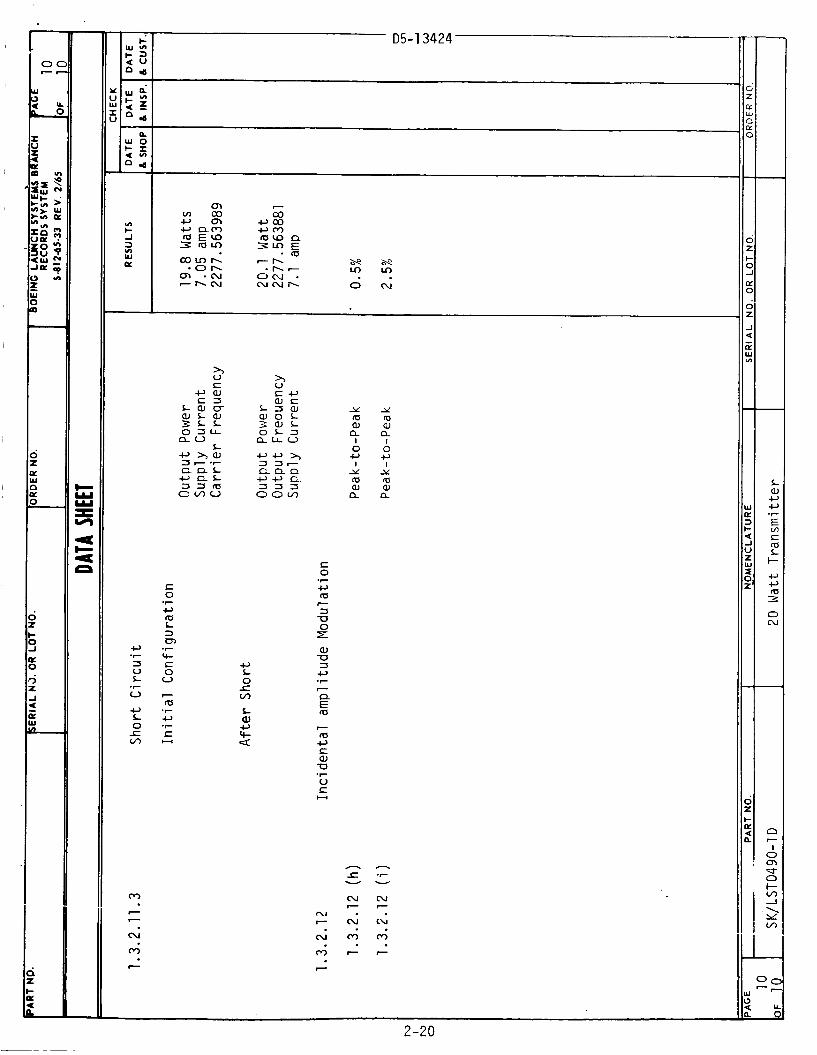
2.1.12.3 Short Circui t (Test Paragraph 1.3.2.11.3)
The units performance was essent ia l ly unchanged by t h i s t e s t , however, before the s ta r t of the t e s t Period the o u t n u t cower was s l i g h t l y below the 20 w a t t requirement, a f t e r the t e s t the power o u t w t was 20.1 watts. before and a f t e r the t e s t Period.
19.8 wat ts ,
Freauency and supply current were within reauirement
2.1.13 Incidental Amplitude Modulation (Test Paragraph 1.3.2.12)
Incidental AM was within reoui rements.
2.1.14 Mi s c e l l aneous Tests
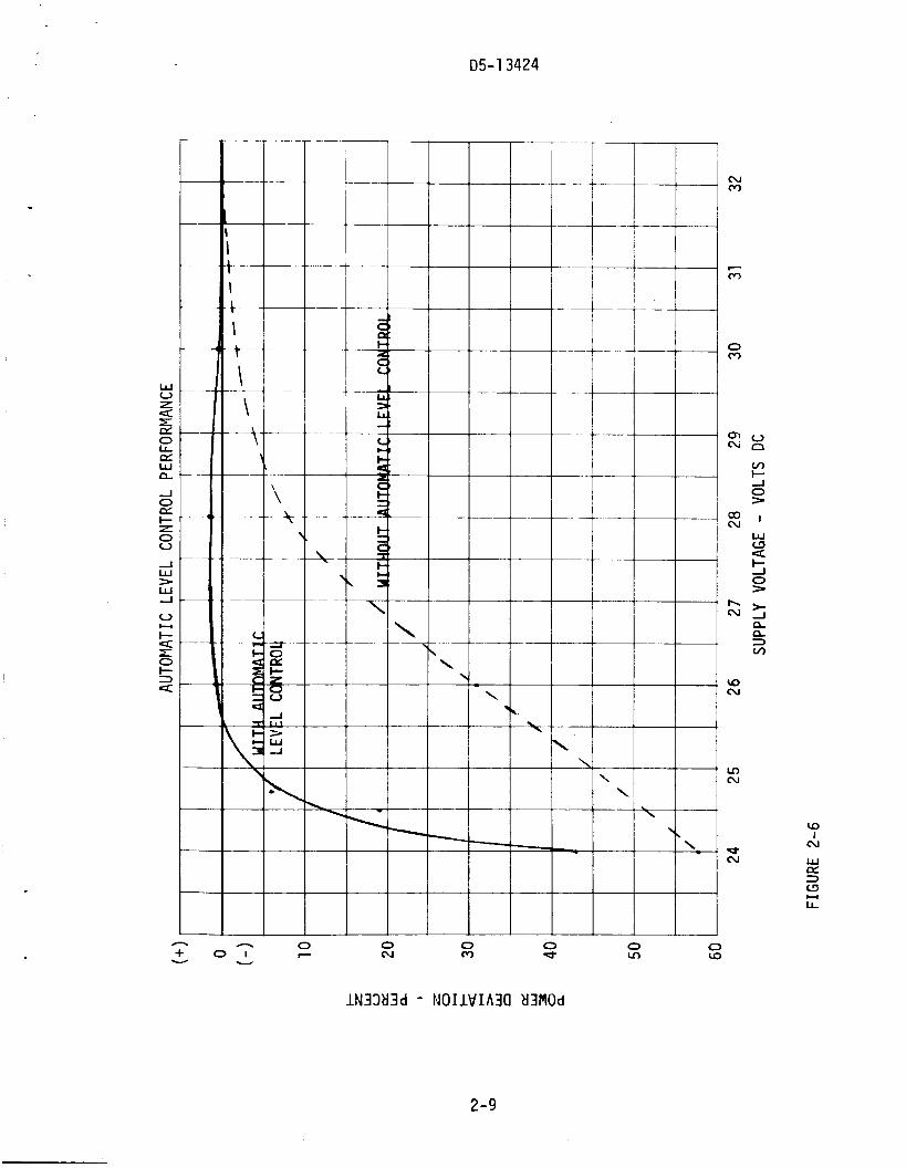
2.1.14.1 Automatic Level Control Performance
A t e s t was conducted t o determine the performance of the automatic level control c i r c u i t , the resul ts a r e shown i n Figure 2-6. T h i s t e s t was conducted by engineering d u r i n g f i n a l assembly of the t ransmit ter .
2.1.14.2 Supply Voltage Levels
During f i n a l assembly sunply voltage leve ls within the t ransmi t te r assemb?y were measured. A voltage dron of approximately one vol t was measured kt;v.ee;; t h e 4np:t cnnnertnr and the Dower amplif ier i n p u t connection. This voltage drop was found t o be almost e n t i r e l y due t o the reverse voltage protection diode used i n s e r i e s w i t h the i n g u t l i n e . T h u s w i t h a
2-8
D5-13424
h 0 (u
n 0 + 0 1 c v u
0 m
0 d
lN33d3d - NOIIVIAXI d3MOd
w
2-9

D5-13424
2.1.14.2 (Cont inued)
24 v o l t i n p u t o n l y 23 v o l t s are a v a i l a b l e t o t h e Dower a m p l i f i e r and p re - d r i v e r / d r i v e r . A t t h i s vo l tage l e v e l these modules a m a r e n t l y have i n - s u f f i c i e n t ga in t o m a i n t a i n the r e q u i r e d o u t o u t rower.
2.14.3 Radio Frequency I n t e r f e r e n c e
A b r i e f aud io f renuency conducted, (power1 i n e ) s u s c e p t i b i l i t y t e s t was made by eng ineer ing . i n t h a t i n c i d e n t a l FFI and AM increased and t h e power o u t n u t decreased. Review o f t h e t e s t setup which was t o be i n accordance w i t h F igu re 17 o f MIL-I-6181D, i n d i c a t e s the 400 MFD c a p a c i t o r was o m i t t e d f rom t h e DC ?over source, t h i s c a p a c i t o r would Probab ly have reduced t h e s u s c e r t i b i 1 i t y somewhat. The u n i t was expected t o be s u s c e p t i b l e t o t h i s t e s t i n t h a t t h e RF1 module design had been o n l y t o c o n t a i n and susnress i n t e r n a l s i g - na l s . I n view o f t h e 1 v o l t drop f rom t h e i n r u t connector t o t h e Dower a m P l i f i e r i t was n o t cons idered d e s i r a b l e t o i n c o r p o r a t e a d d i t i o n a l f i l t e r i n g u n t i l some t e s t s had been conducted.
The u n i t was found t o be s u s c e p t i b l e t o aud io s i g n a l s ,
2-1 0
3 a Q 2 C t- U w v,
I- v, w I-
w n W Q a m . 3 w 3c , Sc, 0 3 0 3 0 3 n o n~ a c
I z- OT
4
2-1 1

v) t -1
w e 2
cv cv
D5-13424
V
> n
a3 cu e
V
> n
n Q 3 v,
W 0, la c, 7
0 >
w V S la -0 a, c E U
c, 3
S a J u W s v m n -0 w n. E
n
H
c, 3 CL S H
E 3 U c C C
I k c
0 C
E
<
1 1
1
! I
2 1
? 2
I
I
L a
D5-13424-
N N N N N r Y I N I I Y Y
I Y Y O Y 0 0 0 0 0 0 0 m-I-LI7l-N
c, 3 n c H
V Q
N
d
N
m 7
03 cu e
u > n 0 V
> > n n
cu m m N
e e
00 N
v u >> 0 0
+ I
nn
. . --
V
5
N m e
n
0 0
>> 0 0
+ I
nn
. . - 7
0
> LD
LD N
e
n
2-13
11 D5-13424
ll 0: w
z 0
n
c, 3 w o 0 0 u v u 0 0 0 u 0 0 0 0 V 0 V 0 v w 0 w 0 w v w 0 w 0 v ti m n n n n n n n n n n nnnnnnn nnnn nnnnnnnna c, > > > > - ~ > > > > > > > > > > > > > > > > > >>>>>>>>> 0 3 z 0 c n c 3 L o o m c o - - m m o o m m m ~ ~ ~ c o e ~ ~ ~ c u c o m m ~ o e o e ~ ~ ~ ,- e ai cu m m e o ~o o v) o m o l c \ l ~ c n m o d L o o m 0 L o 7 M a 7 h N h 7 0 0 N e L o h c J l N L o h O c u m N b U 3 h m N e h O c u m N m m h o c u m h o J (u . . . . . . . . . . . . . . . . . . . . . . . . . . . . . . . -0 0 0 0 0 0 - - 7 - N N ~ 0 0 0 0 0 ~ ~ ~ N N N 0 0 0 0 ~ - ~ - N .' > 0 , z
-1 < Iz: -
v 0 0 0 0 0 0 w v 0 0 0 W 0 0 V 0 V 0 0 0 0 0 u u 0 w u w 0 0 y nnnnnnnnnnn nnnnnnn nnnn nnnonnnnn >>>>>>>>>>> >>>>>>> >>>> > > > > > > > > > > oomocoooooo oomoooooooo ooLooooooo m o c \ l L o o L o o m o m o L o o N m o m o L o o m 0 L o o N L o o m o L o o N m u 3 h O c u L o h O N m NmUJhONLo h O N L o C U L n C O h O c u L o R O
ooool-?77NNN 0 0 0 0 7 7 7 -NNN 0 0 0 0 7 7 7 ~ ( v . . . . . . . . . . . . . . . . . . . . . . . . . . . . . . .
W Iz: 2 I- < -J u z w I 0 z
& ? & ? - L o 7 C U
0 0
II II
N N I I 0 0 0 0 m m c e s s 0 0
W c , m l u > > a a J
N N T I Y Y
m o N O - L o
-
.r- .r-
*r .r-
0
a n
Z I- K
n n
It
I I I1
N N N I X I Y Y Y 0 0 0
N I Y
0 7
e
N N I S Y Y
L n o N O 7 L n
UJ
N
m -
& 2 & 2 C C U J o m 0 0
II II
N N N I I I 9 Y Y
0 0 0 0 0 0
e e e s s O D
c , c , f r s f r s
> > a a J
N N I I Y Y
Loo N O - L n
- 7 7
.r- .r
.r- *r
o n
2-1 4
r
v) t -1
w K
2
W vl S 0 Q m W CZI
h
L W
m 7
D5-13424
Ln m In M m e m m ~ m o ~ a m o ~ a ( u - m n . . . . . . . . . . . . . . . .
0 0 0 0 0 0 0 0 0 0 ~ 0 0 0 ~ 7 + + + + ! I + + + + + + I l l
. . . . . . . . . . . . . . . . 0 - - - r - o o l - ~ ~ ~ ~ ~ 7 c o o
N N N N N N N N N N N N N N N N I I I I I I I I I I I I I I I I Y Y Y Y Y = Y Y Y Y Y Y Y
0 0 0 - m o o o o o o o o o o o m o o v - m o m o ~ o m o I n o
NIn - - n J N m m e b m
N I b
I Y Y 0 V
I ozo 0 0
c, o m 7 w - I m m cc v, 7
r e s w 0 -7 >
L T w 0, W Q - J c c,u -7 7 *r c, s . r 3 - 3 L U O I- s >
o r n o L W M L w u U > .r re .I- .- > u Z W V W m
c, S .F
0 n W V S W L W cc W m
c 0
c, rn 3 U 0 E
e 7
7
3 S 01 3 C W L LL - rn c, C W U
U S
*r
H
7
W > Q) -1
S o r -
al N
m ii
D5-13424- -
0 z X Y
X 0
n
-
0 Z I- O _1
IY 0
0 z J Q
Y W Ln
-
-
U L 3 - a
o s
m I L x m I
N I Y
0
e 7
u -- u c .- o s E O L E I u L I r u I
U s-0 O L v .r W L mt-
2-1 7
2-1 8
c Y w 5
a3 c
w m c
02 N
e
V
> n
N m e
0
> n
In
m N
e
S 0 U W L
E r 0
W O *r Lo SJ u w L L
0 V c e
W W a 0
r m
E r 0 0 In
=-, U S
It 2-1 9
Y Y m c a W a J
I I 0 0 c , W I I
Y Y l a m W a ,
a n
a n
c, L 0 r m L aJ c, cl- Q
S 0
aJ U 3 c, *7
H
2-20

-95-1 3424- I
I -- ! ! ,
I ! I + I
i
i h u; G b 7
a, S 3 3
co a2 M
+ I
cu I h
L n c u h 0 0 -
- =is
L a. c, aJ E L a 3 0 n
. c X L 0
I
-
0
c m '4-
T, -
I
-
4 m d d m
I
-
I
-
-=? L
LL
0 0 c
I
- I
Y I
i 2-21 - 'LE - 2-11 TEST EQUIPMENT
- D5-13424
I
I '\ '
;i
z 1 % c n c n - l-
l
lu i u )
a 'u3 c n m ?
o a, LL
- c 5 3
I . . I
0 M N \ 0
1 u3 m u3
L aJ c, a, E c,
0 > 0 Q
7
L W +' S 3 0 0
I . . I
-
h M 0 -
I
-
n c\J m * -
I
-
z 0 0 *
I
-
X N 3 Y)
!
1 5 l v
2-22 -

I . / \.
' ! I
i 2-23

.
05- 13424
SECTION 3
CONCLUSIONS AND RECOMMENDATIONS
3.0 CONCLUSIONS
3.1 GENERAL
Based on the t e s t s conducted, i t can be concluded t h a t t h e performance o f t h e t r a n s m i t t e r i s w i t h i n to le rance except t o r t h e low power o u t p u t a t the lower supply vo l tage, low e f f i c i e n c y , and t h e l i n e conducted audio i n t e r f e r e n c e .
3.1.1 Power Output
The low power o u t p u t o f the t r a n s m i t t e r a t the lower supply vo l tages was the r e s u l t o f a number o f c o n d i t i o n s which are as f o l l o w s :
a. The excess ive vo l tage drop between the t r a n s m i t t c r i n p u t and the p r e d r i v e r / d r i v e r and power amp1 i f i e r ( g r e a t e r than one v o l t ) .
b. I n s u f f i c i e n t ga in o f the p r e d r i v e r / d r i v e r and power a m p l i f i e r .
c. The change i n o u t p u t impedance o f the power a m p l i f i e r w i t h changes i n supply vo l tage.
d. The impedance mismatch between t h e power a m p l i f i e r and t h e f i r s t tri p l e r .
e . Changes i n t h e dc ou tpu t o f the ALC d e t e c t o r c i r c u i t w i t h changes i n supply vo l tage.
Tile system was o r i g i n a l l y designed t o have s u f f i c i e n t g a i n a t 23.5 v o l t s b u t t h e r e was some degradat ion i n t h i s g a i n when t h e system was t o t a l l y assembled. T h i s degradat ion was m o s t l y due t o t h e i n a b i l i t y t o o b t a i n a good impedance match between t h e power a m p l i f i e r and t h e f i r s t t r i p l e r . The improper impedance match n o t o n l y r e s u l t e d i n lower power t r a n s f e r b u t a l s o considerably d i s t o r t e d t h e waveshape o f t h e s i g n a l a t the o u t p u t o f the power a m p l i f i e r . o f t h e power a m p l i f i e r v a r i e d w i t h changes i n l i n e vo l tage, the impedance match between t h e two modules a l s o changed. This c o n d i t i o n n o t o n l y causes changes I n t h e power t r a n s f e r c h a r a c t e r i s t i c s b u t a l s o had an adverse e f f e c t on the ou tpu t o f the ALC d e t e c t o r c i r c u i t .
The ALC d e t e c t o r a t the ou tpu t o f t h e power a m p l i f i e r c o n s i s t s o f an i n d u c t i v e d i v i d i n q network, i s o l a t i o n capac i to rs and a d e t e c t o r d iode. The dc v o l t a g e o u t o f t h e d e t e c t o r v a r i e s i n p r o p o r t i o n t o t h e peak i n p u t vo l tage. The i n p u t vo l tage f o r t h e d e t e c t o r i n t h i s system i s cons iderab ly d i s t o r t e d and conta ins a l a r g e amount o f second and t h i r d harmonic due t o t h e impedance mismatch of t h e f i r s t t r i p l e r . The amount of harmonic d i s t o r t i o n i n the d e t e c t o r i n p u t s i g n a l v a r i e s as t h e supp ly v o l t a q e i s changed due t o the changing o u t p u t impedance o f t h e power a m p l i f i e r .
Because t h e o u t p u t impedance
The o v e r a l l r e s u l t o f t h i s s i i u d i i i r n i s thci t the clc e u t p u t
3-1
D5-13424
3.1.1 (Cont inued)
.
v o l t a g e o f the d e t e c t o r does n o t remain constant f o r a f i x e d power outpout o f the power a m p l i f i e r as t h e supply v o l t a g e i s var ied, n o r i s t h i s de tec ted o u t p u t vo l tage e x a c t l y l i n e a r w i t h r e s p e c t t o changes i n power a m p l i f i e r o u t p u t power because o f t h e same impedance mismatch.
The major causes of t h e low t r a n s m i t t e r o u t p u t power were due t o the lower than a n t i c i p a t e d vo l tage a t t h e p r e d r i v e r / d r i v e r and power a m p l i f i e r and the impedance mismatch between the power a m p l i f i e r and the f i r s t t r i p l e r . To c o r r e c t t h i s s i t u a t i o n , i t may be p o s s i b l e t o r e - a d j u s t the p r e d r i v e r / d r i v e r and power a m p l i f i e r c i r c u i t s t o o b t a i n s u f f i c i e n t o u t p u t power w i t h a supp ly v o l t a g e o f approx imate ly 22.5 v o l t s . I f s u f f i c i e n t power cannot be obta ined, and a d d i t i o n a l s tage of a m p l i f i c a t i o n may be r e q u i r e d i n the p r e d r i v e r / d r i v e r c i r c u i t . may a l s o be p o s s i b l e t o reduce t h e v o l t a g e drop between t h e supp ly i n p u t t o the t r a n s m i t t e r and t h e two a m p l i f i e r modules by u s i n g two reverse p o l a r i ty p r o t e c t i on diodes i n para1 l e 1 o r by i n c o r p o r a t i n g a d i f f e r e n t type p r o t e c t i o n system.
I t
Component changes w i l l be r e q u i r e d i n the i n p u t c i r c u i t o f t h e f i r s t t r i p l e r i n o r d e r t o o b t a i n an improved impedance match w i t h power a m p l i f i e r . may be r e q u i r e d t o o b t a i n an acceptable matching c a p a b i l i t y .
Some redesign o f t h e f i r s t t r i p l e r i n p u t and i d l e r c i r c u i t s
An improved impedance match between the power a m p l i f i e r and f i r s t t r i p l e r shou ld improve the ALC performance. the sampl ing p o i n t o f the ALC d e t e c t o r cou ld be moved t o t h e o u t p u t of the t h i r d t r i p l e r power adder where t h e r e i s very l i t t l e d i s t o r t i o n present i n the waveform.
I f a problem s t i l l e x i s t s ,
3.1.2 E f f i c i e n c y
Some degradat ion i n t h e dc t o rf e f f i c i e n c y o f t h e t r a n s m i t t e r was caused by impedance mismatches between modules and non-optimum t u n i n g o f t h e modules, e s p e c i a l l y the f requency m u l t i p l i e r s .
As p r e v i o u s l y discussed, the impedance mismatch between t h e power a m p l i f i e r and t h e f i r s t t r i p l e r caused some l o s s i n power t r a n s f e r between these two c i r c u i t s . t h i r d t r i p l e r and the impedance match between t h e second and t h i r d t r i p l e r .
There was a lso some degradat ion i n performance o f t h e
Considerable e f f o r t was expended i n o b t a i n i n g t h e r e q u i r e d performance o f t h e t h i r d t r i p l e r . o f t h i s t r i p l e r were pre-produc t ion u n i t s . i n t o f u l l p r o d u c t i o n o f t h i s dev ice smal l changes were made i n t h e manufac tur ing process. These smal l changes had an adverse e f f e c t on the o p e r a t i o n of the dev ice i n t h i s p a r t i c u l a r c i r c u i t . The problem was n o t so much i n o b t a i n i n g t h e r e q u i r e d e f f i c i e n c y o f t h e u n i t s o p e r a t i n g
The varac tors which were used i n t h e o r i g i n a l des ign When t h e manufac turer went
----.--+-l.* J c p u l a L c l y , Loo+ U U L m n m a ,l l",L ;n , # I n h f a i n j y "I"..... t h p p r m p r n w r ; l t i n n of t.he u n i t s i n
3- 2
D5-13424
3.1.2 (Continued)
para l le l w i t h the power s p l i t t e r and power adder. some s l i g h t chan?e i n the parameters of the varactor caused a change i n the input and/or o u t p u t impedance of the c i r c u i t . additional design e f f o r t , the c i r c u i t could be characterized f o r t h i s new device and higher efficiency obtained.
I t appears t h a t
i4ith some
However, i t i s d i f f i c u l t t o say w h a t improvenent in eff ic iency could be achieved from these improvements in impedance matching. A t the most, the improvements would y ie ld no more t h a n a one per cent overall increase in the t ransmit ter dc t o r f efficiency. What would r e s u l t from these improved impedance matches would be an additional power o u t p u t caoabi 1 i ty of two t o three watts.
3.1.3 Line Conducted, A u d i o Suscept ib i l i ty ( R F I )
The t ransmit ter was very susceptible t o l i n e conducted audio frequencies. The three vol t (rms) signal which was superimposed on the power supply l i n e created consi derable degradation in the system performance. The degradation i n performance was evident in gross measurements of i nci - dental AM and FM and the spurious s ignals contained i n the o u t p u t spectrum. The degradation increased as the frequency of the audio s i g n a l was increased.
About the only solut ion t o th i s problem would be additional f i l t e r i n g of the supply voltage a t the i n p u t t o the t ransmit ter . This would require the a d d i n g of s e r i e s inductance and shunt capacitance t o the RFI f i l t e r of the t ransmit ter . The inductance would cause some increase i n the dc voltage drop of the t ransmit ter supply thereby r e q u i r i n g improved performance of the predriver/driver and power amplifier. possible t o improve the frequency response o f the ALC c i r c u i t and enable i t t o compensate f o r some of the lower frequency interference.
I t may be
3.1.3 Env i ronmental Condi t i ons
T h e t ransmi t te r was not subjected t o any extreme environmental conditions . Because of this , i t i s quite uncertain how the t ransmit ter wil l perform under cer ta in adverse conditions such as h i g h temperature a n d v i b ra t i on. High temperatures would cause some decrease i n power output a n d the dc t o rf eff ic iency of the transmitter. withstand the h i g h temperature envi ornrnents. t ion i n e f f ic iency of t h i s t ransmi t te r , there i s n o t too great a sa fe ty marqin f o r some of the components. e f f ic iency and power o u t p u t o f the t ransmi t te r which have been discussed previously, would enable the t ransmit ter t o operate safely a t the elevated temperatures.
All components were selected t o
The suggestions f o r improving the
However, due t o the degrada-
The degradation of the t ransmit ter performance due t o vibration cannot reaul ly be p y e d i c t e ~ . t e s t i n g i n the pas t , b u t the complete t ransmit ter has not.
- A 2 'I.. Cnw t e s t modules have been subjected t o vibration Ihe mecnanicai
3- 3

D5- 13424
3.1.3 (Cont inued)
design and packaging o f the modules was e f f e c t e d w i t h Kiajor concern be ing a i ven t o the v i b r a t i o n requirements o f the t r a n s m i t t e r .
3.1.4 Spur ious S igna ls
The o u t p u t f requency spectrum of t h e t r a n s m i t t e r conta ined some spur ious s i g n a l s , the ampl i tudes o f which were o n l y 60 db down f rom t h e peak ampl i tude o f t h e c a r r i e r . However, t h e r e were no v i s i b l e spur ious s i g n a l s when a Hewlet t -Packard 608 s i g n a l genera tor was used i n p l a c e o f t h e e x c i t e r / n o d u l a t o r as the t r a n s m i t t e r s i ? n a l source. Nor were t h e r e any spur ious s i g n a l s d i s c e r n i b l e on the o u t p u t o f t h e e x c i t e r / modulator when i t was disconnected f rom the t r a n s m i t t e r and moni tored d i r e c t l y w i t h a spectrum analyzer . The spur ious s i g n a l s must t h e r e f o r e be the r e s u l t o f adverse impedance matching o r l o a d i n g c o n d i t i o n s o f the p r e d r i v e r / d r i v e r assembly. There are two p o s s i b l e s o l u t i o n s f o r t h i s problem. a t t h e i n p u t o f the p r e d r i v e r / d r i v e r . would be t o add a b u f f e r i n g o f e m i t t e r f o l l o w e r s tage t o t h e exci ter , ’ modulator . The spur ious s i g n a l s c o u l d g e n e r a l l y be reduced b y t u n i n g o f t h e e x c i t e r / n o d u l a t o r bandpass f i l t e r s and o u t p u t coup l ing , b u t they c o u l d n o t be complete ly e l i m i n a t e d by t h i s procedure.
One would be the a d d i t i o n o f an impedance matching network The o t h e r p o s s i b l e s o l u t i o n
3.2 RECOMMENDATIONS
The l i m i t e d t e s t s which have been performed on t h i s t r a n s m i t t e r have shown the b a s i c system design t o be e f f e c t i v e and sound. d a t a and t h e t ime expended i n t h e development o f t h i s t r a n s m i t t e r a l s o show t h a t a d d i t i o n a l c i r c u i t des ign improvements a re r e q u i r e d b e f o r e the t r a n s m i t t e r can be manufactured i n l i m i t e d q u a n t i t i e s on a p r o d u c t i o n b a s i s .
The t e s t
The system design , whi ch has t h e e x c i ter /modul a t o r o p e r a t i n g a t a f requency o f approx imate ly 84 MHz f o l l o w e d by a power a m p l i f i e r and a t imes 27 f requency m u l t i p l i e r , i s by no means an u l t i m a t e des ign and can be i m - proved upon as t h e s t a t e - o f - t h e - a r t i n semi conductors advances. may now be p o s s i b l e , w i th the r e c e n t advances i n rf t r a n s i s t o r technology, t o operate t h e power a m p l i f i e r a t a f requency o f 250 MHz i n s t e a d o f 84 MHz. T h i s change would e l i m i n a t e t h e f i r s t t r i p l e r and some o f t h e assoc ia ted problems of e f f i c i e n c y and impedance matching.
I t
The h i g h e r frequency power a m p l i f i e r would a l s o a l l o w more optimum f requenc ies t o be s e l e c t e d f o r t h e e x c i ter /modul a t o r c r y s t a l os c i 11 a t o r and vo l tage c o n t r o l o s c i 1 l a t o r w i t h r e s p e c t t o suppress ion o f m i x e r generated i n t e r m o d u l a t i o n products . Some of these in termodul a t i o n produc ts may be the source o f t h e spur ious s i g n a l s i n t h e o u t p u t f requency spectrum of t h e present t r a n s m i t t e r .
The one c i r c u i t which i i m i i s tiic apei-Gticn;l ?er?%rm?nce nf t h e t r a n s - m i t t e r i s t h e t h i r d t r i p l e r . There i s no s i n g l e v a r a c t o r on the market
3-4
D5- 1 3424
3.2 (Cont inued)
today capable o f h a n d l i n g t h e power and p r o v i d i n g the r e q u i r e d e f f i c i e n c y f o r t h i s c i r c u i t . Th is inc ludes t h e var ious R & D devices t h a t t h e manufacturers are work ing on a t t h e p r e s e n t t i n e . types o f devices f o r t h e f u t u r e a re t h e new s e r i e s - c h i p u n i t s t h a t some manufacturers are developing. However, i t i s e s t i m a t e d t h a t u n i t s f o r a p p l i c a t i o n i n t h i s t r a n s m i t t e r w i l l n o t be i n p i l o t l i n e p r o d u c t i o n f o r a t l e a s t a year .
The most p romis ing
Th is then means t h a t two varac tors w i l l cont inue t o be r e q u i r e d i n the t h i r d tri p l e r i n o r d e r t o p r o v i d e t h e power h a n d l i n g capabi 1 i ty.
Using a doubler i n s t e a d o f a t r i p l e r i n t h e f i n a l f requency m u l t i p l i e r w i l l n o t improve t h e o v e r a l l performance o f the system. Two devices w i l l s t i l l be r e q u i r e d i n o r d e r t o handle the power. Al though a doub ler i s more e f f i c i e n t than a t r i p l e r , t h e doub ler w i l l be o p e r a t i n g a t a h i g h e r i n p u t f requency which w i 11 reduce t h e e f f i c i e n c y t o approx imate ly t h a t o f t h e t r i p l e r . Another f a c t o r t o be considered i s t h a t i f t h e f i n a l m u l t i p l i e r i s a doubler , e i t h e r t h e power a m p l i f i e r w i l l have t o operate a t a h i g h e r f requency o r more m u l t i p l i c a t i o n s tages w i l l be r e q u i r e d . The l e a s t number o f m u l t i p l i c a t i o n stages used, t h e more e f f i c i e n t t h e system w i l l be.
The t h i r d t r i p l e r by i t s e l f i s q u i t e e f f i c i e n t . of 55 percent have been achieved when o p e r a t i n g a s i n g l e dev ice w i t h 25 w a t t s o f d r i v e power. Degrading o f t h e t h i r d t r i p l e r occurs when the two t r * i p l e r s are mated together i n t h e p a r a l l e l c o n f i g u r a t i o n w i t h t h e power s p l i t t e r and power adder. Some power i s l o s t i n t h e s p l i t t e r and adder, p l u s power i s l o s t due t o de tun ing o f t h e t r i p l e r s . It i s q u i t e p o s s i b l e t h a t t h e t h i r d t r i p l e r performance c o u l d be s i g n i f i - c a n t l y improved by o p e r a t i n g t h e two varac tors i n a push-pu l l con- f i g u r a t i o n . Th is c o u l d be accompli shed w i t h e i t h e r coaxi a1 c a v i t i e s o r microwave s t r i p l i n e techniques.
E f f i c i e n c i e s i n excess
Another p o s s i b l e improvement i n t h e system would be t o i n c o r p o r a t e w i th e i t h e r t h e t h i r d t r i p l e r o r t h e bandpass f i l t e r a d e t e c t o r t o sense r e f l e c t e d power of t h e t r a n s m i t t e r ou tpu t . T h i s d e t e c t o r v o l t a g e c o u l d be used w i t h t h e p r e s e n t ALC c i r c u i t t o p r o t e c t t h e t r a n s m i t t e r f rom a h i g h VSWR a t t h e t r a n s m i t t e r ou tpu t . then be e l i m i n a t e d and approx imate ly a one w a t t inc rease i n power o u t p u t c o u l d be r e a l i z e d .
The need f o r an i s o l a t o r would
Any one of t h e preced ing recommendations by i t s e l f does n o t o f f e r any g r e a t improvement i n the o v e r a l l t r a n s m i t t e r performance. However, if each were t o be i n c o r p o r a t e d i n t o t h e t r a n s m i t t e r an o v e r a l l improve- ment o f s e v e r a l w a t t s c o u l d be expected i n t h e power o u t p u t c a p a b i l i t y of t h e t r a n s m i t t e r . of approx imate ly 30 w a t t s f o r a t r a n s m i t t e r which i s tuned t o optimum. l i m i t e d p r o d u c t i o n t r a n s m i t t e r w i i i ~ d riiii-~i~i-iiii o u t p ~ t ef 25 w; l t ts fnr a1 1 env i ronmenta l c o n d i t i o n s may then be p o s s i b l e .
T h i s would r e s u l t i n a power o u t p u t c a p a b i l i t y A
3- 5

I .
D5- 1 3424
3.2 (Conti nued)
The main problem w i t h the present t ransmit ter i s t h a t every module must be turned and adjusted f o r opt imum performance in order t o approach the minimum requirements of the t ransmit ter . I t i s almost a cer ta in ty t h a t the present t ransmit ter could meet a l l o f the required performance charac te r i s t ics i f i t s power o u t p u t were limited t o 15 watts.
Although the performance of this t ransmit ter has fa l len short o f some o f the design goals, i t s development has subs tan t ia l ly advanced the power o u t p u t and frequency range o f so l id s t a t e t ransmit ters . development has a lso proven t h a t the basic system design i s sound and the overall performance o f the t ransmit ter can be improved t o meet the design goals with some modification of the basic c i r c u i t s .
The
3-6