final project report wecc wind generator...
TRANSCRIPT
FINAL PROJECT REPORT
WECC WIND GENERATOR DEVELOPMENT
Prepared for CIEE By:
National Renewable Energy Laboratory
Project Manager: Eduard Muljadi Authors: Edward Muljadi, Abraham Ellis Date: March, 2010
A CIEE Report

i
Acknowledgments
The support of the U.S. Department of Energy (DOE), the Western Electric Coordinating
Council (WECC), and the California Energy Commissionʹs PIER Program are gratefully
acknowledged.
The author expresses his gratitude to the members WECC Wind Generator Modeling Group
(WGMG) and Model Validation Working Group (MVWG), General Electric, Siemens PTI who
have been instrumental in providing technical support and reviews, and, guidance during the
development of this project.
DISCLAIMER
This draft report was prepared as the result of work sponsored by the California Energy Commission. It does not necessarily represent the views of the Energy Commission, its employees or the State of California. The Energy Commission, the State of California, its employees, contractors and subcontractors make no warrant, express or implied, and assume no legal liability for the information in this report; nor does any party represent that the uses of this information will not infringe upon privately owned rights. This report has not been approved or disapproved by the California Energy Commission nor has the California Energy Commission passed upon the accuracy or adequacy of the information in this report.

ii
Preface ..
The California Energy Commission’s Public Interest Energy Research (PIER) Program supports
public interest energy research and development that will help improve the quality of life in
California by bringing environmentally safe, affordable, and reliable energy services and
products to the marketplace.
The PIER Program conducts public interest research, development, and demonstration (RD&D)
projects to benefit California.
The PIER Program strives to conduct the most promising public interest energy research by
partnering with RD&D entities, including individuals, businesses, utilities, and public or
private research institutions.
PIER funding efforts are focused on the following RD&D program areas:
Buildings End‐Use Energy Efficiency
Energy Innovations Small Grants
Energy‐Related Environmental Research
Energy Systems Integration
Environmentally Preferred Advanced Generation
Industrial/Agricultural/Water End‐Use Energy Efficiency
Renewable Energy Technologies
Transportation
The draft final report for the Western Electricity Coordinating Council (WECC) Wind Generator
Development project (contract number 500‐02‐004, work authorization number MR‐065), is the
summary of activities reported in separate interim reports:
WIND POWER PLANT EQUIVALENCING
WIND POWER PLANT DATA COLLECTION
MODEL VALIDATION OF WIND TURBINE GENERATOR
This project is sponsored by the WECC‐WGMG, California Energy Commission (Energy
Commission), and the National Renewable Energy Laboratory (NREL). The information from
this project contributes to PIER’s Energy Systems Integration Program.
For more information about the PIER Program, please visit the Energy Commission’s website at
www.energy.ca.gov/research/ or contact the Energy Commission at 916‐654‐4878.
iii
Table of Contents
Preface .. ............................................................................................................................................. ii
Abstract and Keywords ..................................................................................................................... vi
Executive Summary ........................................................................................................................... 1
1.0 Introduction and Scope ........................................................................................................... 3
2.0 Description of Wind Turbine Generator Technologies ....................................................... 5
Type 1 – Fixed‐speed, induction generator ............................................................................... 5
Type 2 – Variable slip, induction generator with variable rotor resistance .......................... 6
Type 3 – Variable speed, doubly‐fed asynchronous generators with rotor‐side converter 6
Type 4 – Variable speed generators with full converter interface ......................................... 7
3.0 Wind Power Plant and Power Flow Equivalencing ............................................................ 8
4.0 Wind Power Plant Data ........................................................................................................... 10
4.1 Data for steady‐state representation .................................................................................... 11
Power Flow Network Data ................................................................................................ 11
4.2 Data for dynamic analysis ..................................................................................................... 12
The process of creating a dynamic file for a WTG ......................................................... 12
4.3 Data for WTG Model Validation .......................................................................................... 13
Infinite bus representation................................................................................................. 13
Field Measurement for Dynamic Data for Model Validation ...................................... 14
The per phase voltage waveforms .................................................................................... 14
Processing Data for PSLF Simulation – Model Validation Exercise ............................ 14
5.0 Model Validation of Wind Turbine Generator .................................................................... 16
5.1 Validation against the field measurements ......................................................................... 16
5.2 Validation against the detailed (manufacturer specific) models ..................................... 17
6.0 Summary and Dissemination ................................................................................................. 19
7.0 Future Plan ................................................................................................................................ 20
References ........................................................................................................................................... 21
Glossary . ............................................................................................................................................ 22
Appendix I ‐ List of Publications ..................................................................................................... I
Appendix II ‐ List of Short Courses and Workshops .................................................................... II
Appendix III ‐ Wind Power Plant Equivalencing .......................................................................... III
Appendix IV ‐ Wind Power Plant Data Collection ....................................................................... IV
Appendix V ‐ Model Validation of Wind Turbine Generator ..................................................... V

iv
Appendix VI ‐ WECC Wind Power Plant Power Flow Modeling Guide .................................. VI
Appendix VII ‐ WECC Wind Power Plant Dynamic Modeling Guide ...................................... VII
v
List of Figures
Figure 1 ‐ Four different types of wind turbine generator ................................................................... 5
Figure 2 ‐ Physical diagram of a typical WPP ........................................................................................ 8
Figure 3 ‐ Single turbine representation for a WPP............................................................................... 9
Figure 4 – Steady state and dynamic data groupings. ........................................................................ 11
Figure 5 ‐ Single‐machine equivalent impedance of NMEC‐WPP ................................................... 12
Figure 6 ‐ Dynamic model input preparation ...................................................................................... 13
Figure 7 ‐ The per‐phase‐voltages van, vbn , and vcn as recorded ........................................................ 14
Figure 8 ‐ Block diagrams indicating the flow process to convert the monitored voltage into the
input data for GENCLS module .................................................................................................... 15
Figure 9 ‐ Input data to GENCLS to perform the dynamic simulation ........................................... 15
Figure 10 ‐ Comparison between the generic model and the measured data for a Type 2 and
Type 3 WTG. ..................................................................................................................................... 16
Figure 11 ‐ Comparison between the generic model and the detailed model for a Type 1 WTG. 18
Figure 12 ‐ Comparison between the generic model and the detailed model for a Type 4 WTG. 18
vi
Abstract and Keywords
Wind energy continues to be one of the fastest‐growing power generation sectors. This trend is
expected to continue globally as we attempt to meet a growing electrical energy demand in an
environmentally responsible manner. As the number of wind power plants (WPPs) continues
to grow and the level of penetration becomes high in some areas, there is an increased interest
on the part of power system planners in methodologies and techniques that can be used to
adequately represent WPPs in interconnected power system studies. This project is part of an
overall industry effort to develop, validate and implement generic positive‐sequence stability
models for wind power plants (WPP). Although the models are designed specifically to meet
Western Electricity Coordinating Council (WECC) modeling requirements, the results also
benefit the industry as a whole. These goals represent challenges, some of which are described
below:
There are currently four major different types of wind generators, and all of them are
fundamentally different from conventional generators. It is necessary to have different
types of wind turbine generator (WTG) dynamic models to closely represent each of the
four types.
Wind turbine generators are a relatively new kind of technology where significant
technical innovation is still occurring. Thus, planning models were not readily available
until recently. From an engineering point of view, representing WPPs as negative loads
or conventional generators is unacceptable. With the recent development and
implementation of WECC generic models of WTGs, wind power plants can now be
represented more properly.
WPPs are topologically complex. Typical plants have hundreds of turbines spread over
a very large area, interconnected by miles of radial feeder circuits, and finally connected
to the utility grid at the point of interconnection (POI). In grid planning studies, it is
impractical to represent this complex system explicitly. Although each WPP has unique
characteristics (e.g. terminal voltage, wind condition, line impedance, etc), it is necessary
to find a reasonable equivalent representation that reproduces the important plant
behavior as seen from the POI.
Validation of dynamic models is needed to verify that the models closely match the
dynamic behavior of actual equipment. Field measurement can be used to validate WPP
models. Since suitable field data is difficult to obtain, model verification by comparison
to manufacturer‐specific, higher‐order (more detailed), and validated dynamic models
can be used.
Models have limited value unless they are well documented and made available to grid
planners in the simulation platforms of their choice. For this reason, this project aimed at
implementing the models in simulation platforms that are typically used for grid
planning (GE PSLF and Siemens‐PTI PSSE). In addition, dissemination of the project

vii
results is accomplished via publications at the appropriate conferences, websites,
workshops, seminars, and, short courses.
In this report, we summarize the project which covers dynamic model development of four
types of wind turbine generators, data collection needed for model validation, power flow wind
power plant equivalencing, model validation, and modeling guidelines developed for WECC.
The interim reports are included as appendices of this final report. The generic dynamic model
of four types of wind turbine generator has been implemented on two major power system
simulation platforms: Siemens‐PTI PSSE and General Electric PSLF. The term “generic” is used
to refer to the dynamic model that does not contain proprietary information protected by wind
turbine manufacturers. These dynamic models of WTG are now part of the standard model
library in PSSE and PSLF. The modeling guides are publicly available at the WECC website1.
Keywords: Dynamic model, equivalencing, model validation, wind power plant, wind
turbine, wind integration, and system integration.
1 http://www.wecc.biz/library/WECC%20Documents/Documents%20for%20Generators/Generator%20Testing%20Program/Wind%20Generator%20Power%20Flow%20Modeling%20Guide.pdf
- 1 -
Executive Summary
It is expected that large amounts of wind capacity will continue to be added to the power
system. The size of individual turbines has increased dramatically from a mere several
hundred kilowatts to multi megawatt turbines. The size of individual wind power plants
(WPPs) has also increased significantly. In the past, a typical WPP consisted of several turbines.
Today, typical WPP nameplate capacity is 100MW to 200MW. Total capacity in a region or
cluster can reach 1 GW or more. By some projections, as much as 20 GW of additional wind
generation capacity may be added in the Western Electricity Coordinating Council (WECC)
footprint within the next 10 – 15 years. The increase in level of penetration of renewable energy
generation in the WECC region, and California in particular, poses significant challenges
concerning the ability of the power system to maintain reliable operation.
For many years, lack of open access to adequate models has resulted in much of the wind
capacity being modeled as conventional induction machines or negative loads in regional
planning studies. The increased use of this energy source necessitates a more accurate
representation of installed wind capacity. Misrepresentation of a WPP in a dynamic model
reduces confidence in the transmission planning process and can lead to erroneous conclusions.
Manufacturer‐specific, proprietary models are made available for interconnection studies;
however, their use is also challenging in practice. The overall goal of the generic modeling
effort is to address these challenges.
The Wind Generator Modeling Group (WGMG) has completed the first phase development and
implementation of generic wind turbine models. Four generic models produced by this effort
represent the types of turbines that currently hold the largest market share in the North
American region. WECC is interested in ensuring that accurate and validated models of
standard wind turbines are readily available for regional studies. This means that the models
should be suitable for inclusion in the WECC standard dynamic model database. The
availability of data sets for testing the models is critical to meet WECC’s model validation
requirements. WECC is also interested in guidelines discussing the methods of representing a
WPP in power system studies. These goals are reflected in the functional guidelines of the
WECC WGMG. The WECC models will be generic in nature, that is, they do not require nor
reveal proprietary data from the turbine manufacturers.
These improved, standard (i.e., generic, non‐proprietary) dynamic models would enable
planners, operators, and engineers to plan and operate the system taking into account the
characteristics capabilities of modern wind turbines (e.g., dynamic, variable, reactive power
compensation, dynamic generation shedding capability, and soft‐synchronization with the
grid). With the appropriate dynamic models available for wind turbines, planners could more
accurately study transmission congestion or other major grid operating constraints, either from
a real‐time grid operations or transmission planning perspective. These models could be used
by transmission planners in expanding the capacity of existing transmission facilities to
accommodate wind energy development in a manner that benefits electricity consumers.
- 2 -
This has become increasingly important as the penetration amounts of wind energy systems
have increased. The WECC‐WGMG efforts also provides opportunities for researchers at
universities and national laboratories to more easily access to wind turbine models and conduct
research.
This report is the final report for the WECC Wind Generator Development Project, contract
number #500‐02‐004, work authorization number MR‐065, a project sponsored by the WECC‐
WGMG, California Energy Commission (Energy Commission), and National Renewable Energy
Laboratory (NREL). This report summarizes the activities performed in this project as reported
in the interim reports:
Wind Power Plant Equivalencing
Wind Power Plant Data Collection
Model Validation of Wind Turbine Generator
Two WECC guides were published by WECC‐WGMG:
WECC Wind Power Plant Power Flow Modeling Guide
WECC Wind Power Plant Dynamic Modeling Guide (currently posted for comment
through the WECC Modeling and Validation Work Group)
The generic models of wind turbine generators (Type 1 – Type 4) have been developed and are
now included in the standard model library of the PSSE and PSLF software platforms. The
generic models are also being implemented in two other software platforms: Operation
Technology ETAP, and Powertech Labs DSA Tools. Results from this project have been widely
disseminated through presentations at workshops and short courses conducted at meetings and
conferences sponsored by WECC, IEEE, Utility Wind Integration Group (UWIG), and
universities. During the progress of this project, technical reports, and conference papers were
also published at different conferences.
‐ 3 ‐
1.0 Introduction and Scope This report summarizes the results accomplished at the time of project conclusion. Before
WECC‐WGMG embarked on working on dynamic models of wind turbine generators,
availability of appropriate models for representation of WPPs were limited. For the most part,
only manufacturer‐specific user‐written models were available on a limited basis (through non‐
disclosure agreements) for the purposes of conducting interconnection studies. These types of
dynamic models are developed in full detail, including information deemed to be proprietary
by the turbine manufacturers. Manufacturer‐specific models sometimes are not fully
integrated into the standard model library of simulation software, which leads to model
maintenance and compatibility issues. Also, difficulties sometimes occur when we want to
study an area with several WPPs from multiple manufacturers. Compatibility issues, limited
access to models and long technical support iterations often results in long delays to complete
the studies. After projects are completed, the proprietary nature of the models prevents their
inclusion in the WECC standard dynamic database for the purposes of conducting regional
studies.
With funding from WECC, CEC and DOE, and support from several organizations including
DOE and Sandia, the WECC‐WGMG completed the first phase of the effort to develop and
implement wind turbine generator (WTG) dynamic models. The WECC dynamic models are
intended to be generic in nature and non‐proprietary, and thus are readily available for use.
Generic models allow for unique characteristics of WTGs from different manufacturers to be
represented by adjusting model parameters. These WECC dynamic models are currently
available in the library of the PSLF (developed by GE) and PSSSE (developed by Siemens PTI).
Default input data for each models is also provided. The generic models are also being
implemented in two other software platforms: Operation Technology ETAP, and Powertech
Labs DSA Tools.
This report is organized as follows:
Section 1 – Introduction and Project Scope
Section 2 – Background
o This section provides background of different tasks considered in this project
Section 3 – Description of Four different types of Wind Turbine Generator Technologies
Section 4 – Wind Power Plant Equivalencing
o This section describes the equivalencing method used to represent hundreds of
turbine within the WPP as a reduced model for bulk system planning.
Section 5 – Wind Power Plant Data
o This section describes the data needed to simulate and validate WPP.
Section 6 –Model Validation of Generic Models for Wind Turbine Generators
o This section describes the method used to validate WPP
Section 7 –Summary and Dissemination

‐ 4 ‐
o This section describes the summary and dissemination to the public
Section 8 –Future Plans
o This section describes the plan to expand the modeling effort
‐ 5 ‐
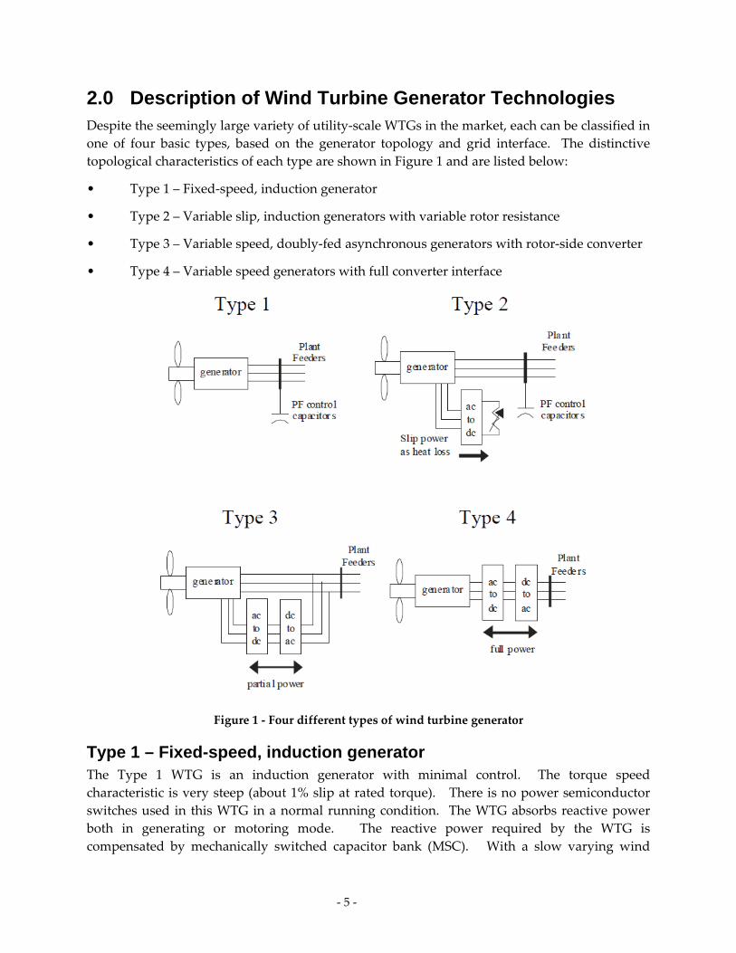
2.0 Description of Wind Turbine Generator Technologies Despite the seemingly large variety of utility‐scale WTGs in the market, each can be classified in
one of four basic types, based on the generator topology and grid interface. The distinctive
topological characteristics of each type are shown in Figure 1 and are listed below:
• Type 1 – Fixed‐speed, induction generator
• Type 2 – Variable slip, induction generators with variable rotor resistance
• Type 3 – Variable speed, doubly‐fed asynchronous generators with rotor‐side converter
• Type 4 – Variable speed generators with full converter interface
Figure 1 ‐ Four different types of wind turbine generator
Type 1 – Fixed-speed, induction generator The Type 1 WTG is an induction generator with minimal control. The torque speed
characteristic is very steep (about 1% slip at rated torque). There is no power semiconductor
switches used in this WTG in a normal running condition. The WTG absorbs reactive power
both in generating or motoring mode. The reactive power required by the WTG is
compensated by mechanically switched capacitor bank (MSC). With a slow varying wind

‐ 6 ‐
speed, the MSC is able to follow the reactive power variation and the terminal voltage is very
closely regulated. Under fast transients, the terminal voltage may be lagging in response and a
wider voltage and output variation can be expected. Similarly, with sudden changes in
frequency, the output power may respond instantaneously without any output current
restrictions, thus, a frequency response similar to a synchronous generator can be expected.
Type 2 – Variable slip, induction generator with variable rotor resistance The Type 2 WTG is a wound rotor induction generator with the capability to adjust the effective
external rotor resistance. The effective value of the external rotor resistance is adjustable via a
simple three‐phase diode rectifier, DC chopper, and a parallel resistance. Thus effectively, the
WTG can be controlled to deliver a constant rated power for wind speeds higher than rated by
adjusting the total rotor resistance. Below rated wind speeds (low to medium wind speeds), the
operation of Type 2 WTGs is very similar to the operation of Type 1 WTGs. In the high wind
speed region, the WTG generates constant output power, output currents, and output power
factor. Although the external rotor resistance is capable of maintaining constant output power
at higher slips, the heat loss within the rotor resistance can be very high at higher slips. The
pitch controller of the WTG is usually adjusted to keep the slip to be as close as possible to the
rated slip when the WTG operates in high wind speed. The WTG of this type tends to react
faster to sudden (transient) changes than WTG Type 1 because of its ability to maintain the
output real and reactive power with the adjustable external rotor resistance and pitch controller.
Thus, a sudden wind gust does not produce large power and reactive power surges, nor voltage
drops like with Type 1 WTGs.
Type 3 – Variable speed, doubly-fed asynchronous generators with rotor-side converter The Type 3 WTG is also known as doubly‐fed induction generator (DFIG). Type 3 and Type 4
WTGs include a power converter to control the WTG. In a Type 3 WTG the rotor winding is
connected to the power converter and the stator winding is connected to the grid. Under
normal conditions or small transients, the power converter controls the output power of the
generator, reactive power or bus voltage. It can control the real and reactive power
independently and instantaneously. The power converter controls the stator output via
electromagnetic coupling between stator and rotor separated by the air gap. Under severe
disturbance (i.e., fault transients), the stator winding is exposed to abnormal and unbalanced
voltage due to the faults that occur in the transmission lines. As a result, the power converter
may lose its ability to control the output of real and reactive power, and it may have to apply
the crowbar mechanism to protect the DC bus from an over voltage condition. The crowbar in
effect is shorting the rotor winding, thus, making the rotor winding appear like a squirrel‐cage
induction generator. The temporary imbalance between the aerodynamic power and the
electrical output power may accelerate the rotor speed. To limit the rotor speed, the pitch
controller adjusts the pitch angle of the blades to avoid an over speed condition.

‐ 7 ‐
Type 4 – Variable speed generators with full converter interface For the Type 4 WTG, the power converter acts as a buffer between the grid and the electric
generator, thus, any transients occurring in the grid are not translated to the electric generator.
Under normal or fault transients, the power converter can be fully controlled. However, one
should realize that the power converter has a current limit to protect the output current of the
power semiconductors (e.g. IGBT and diodes), and when the grid voltage is low during a fault
transient disturbance, the maximum output power that can be delivered to the grid is also
limited. Thus, the pitch controller will limit the rotor speed from over‐speeding avoiding a run‐
away situation.
‐ 8 ‐
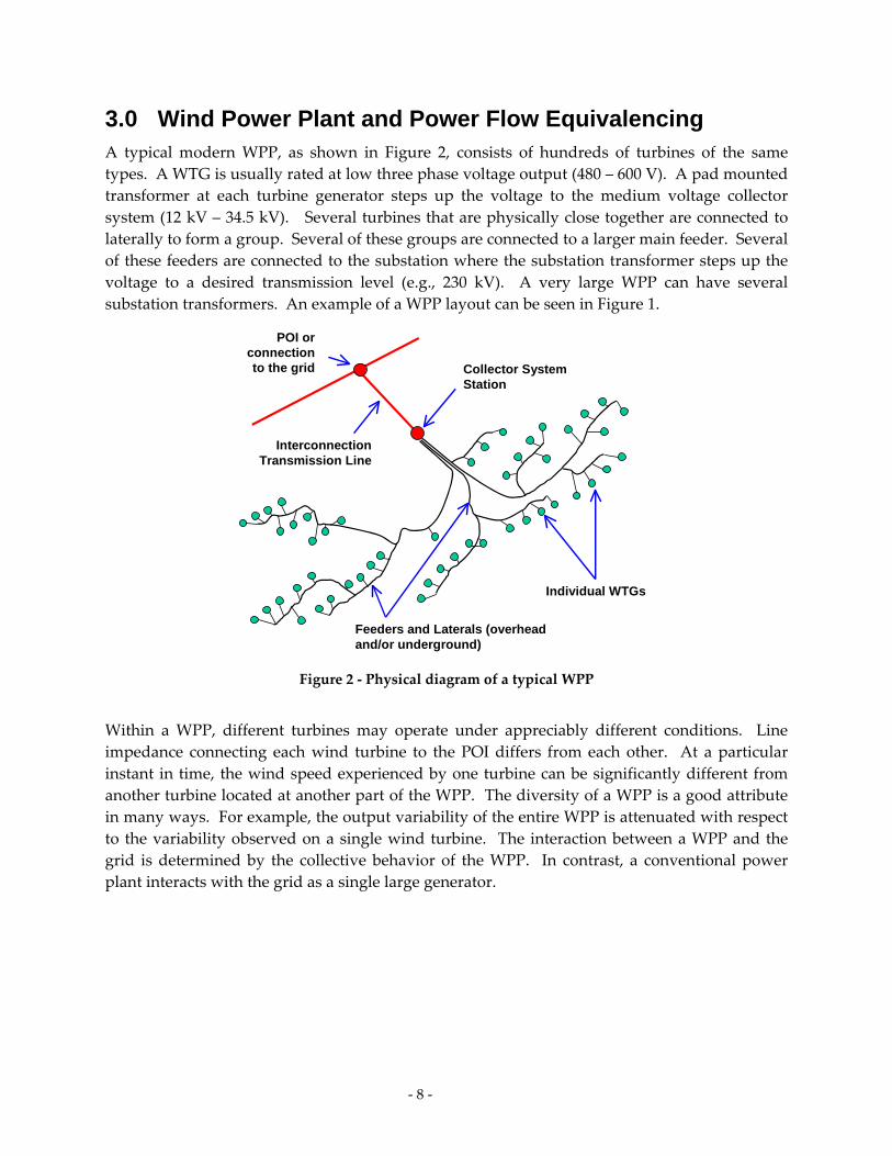
3.0 Wind Power Plant and Power Flow Equivalencing A typical modern WPP, as shown in Figure 2, consists of hundreds of turbines of the same
types. A WTG is usually rated at low three phase voltage output (480 – 600 V). A pad mounted
transformer at each turbine generator steps up the voltage to the medium voltage collector
system (12 kV – 34.5 kV). Several turbines that are physically close together are connected to
laterally to form a group. Several of these groups are connected to a larger main feeder. Several
of these feeders are connected to the substation where the substation transformer steps up the
voltage to a desired transmission level (e.g., 230 kV). A very large WPP can have several
substation transformers. An example of a WPP layout can be seen in Figure 1.
POI or connection to the grid Collector System
Station
Feeders and Laterals (overhead and/or underground)
Individual WTGs
Interconnection Transmission Line
Figure 2 ‐ Physical diagram of a typical WPP
Within a WPP, different turbines may operate under appreciably different conditions. Line
impedance connecting each wind turbine to the POI differs from each other. At a particular
instant in time, the wind speed experienced by one turbine can be significantly different from
another turbine located at another part of the WPP. The diversity of a WPP is a good attribute
in many ways. For example, the output variability of the entire WPP is attenuated with respect
to the variability observed on a single wind turbine. The interaction between a WPP and the
grid is determined by the collective behavior of the WPP. In contrast, a conventional power
plant interacts with the grid as a single large generator.
‐ 9 ‐
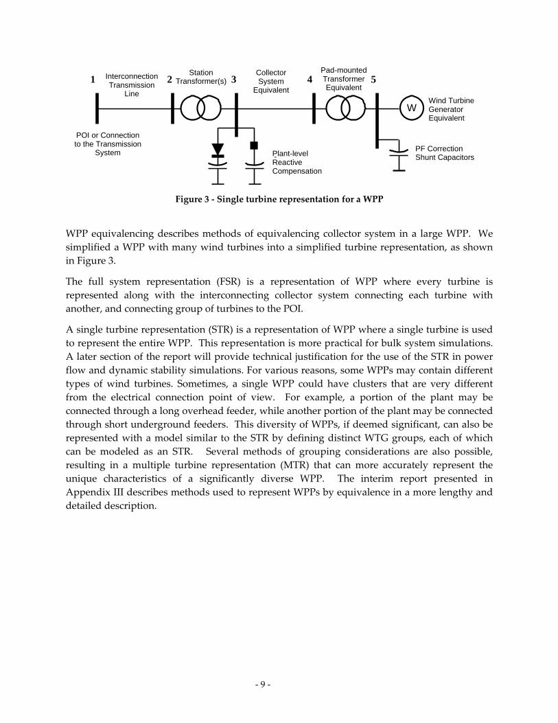
WPP equivalencing describes methods of equivalencing collector system in a large WPP. We
simplified a WPP with many wind turbines into a simplified turbine representation, as shown
in Figure 3.
The full system representation (FSR) is a representation of WPP where every turbine is
represented along with the interconnecting collector system connecting each turbine with
another, and connecting group of turbines to the POI.
A single turbine representation (STR) is a representation of WPP where a single turbine is used
to represent the entire WPP. This representation is more practical for bulk system simulations.
A later section of the report will provide technical justification for the use of the STR in power
flow and dynamic stability simulations. For various reasons, some WPPs may contain different
types of wind turbines. Sometimes, a single WPP could have clusters that are very different
from the electrical connection point of view. For example, a portion of the plant may be
connected through a long overhead feeder, while another portion of the plant may be connected
through short underground feeders. This diversity of WPPs, if deemed significant, can also be
represented with a model similar to the STR by defining distinct WTG groups, each of which
can be modeled as an STR. Several methods of grouping considerations are also possible,
resulting in a multiple turbine representation (MTR) that can more accurately represent the
unique characteristics of a significantly diverse WPP. The interim report presented in
Appendix III describes methods used to represent WPPs by equivalence in a more lengthy and
detailed description.
W
Pad-mounted Transformer Equivalent
Wind Turbine Generator Equivalent
PF CorrectionShunt Capacitors
Collector System
Equivalent
Interconnection Transmission
Line
-Plant-level Reactive Compensation
POI or Connection to the Transmission
System
Station Transformer(s)1 2 3 4 5
Figure 3 ‐ Single turbine representation for a WPP
‐ 10 ‐
4.0 Wind Power Plant Data The data required can be divided into two parts; the steady state data needed to solve the
power flow portion of dynamic simulation, and the dynamic data needed to solve the electro‐
mechanical interaction between the grid and the WTGs. A more detailed discussion about
wind plant data required to simulate WPP and to validate a WTG dynamic model can be found
in Appendix IV.
The steady‐state data is mostly power system network data from the WPP and its reactive
power capability. This includes power factor correction capacitors at the WTG terminals or
reactive power support equipment (e.g., capacitors, STARCOM or similar) located elsewhere in
the WPP. Since a WPP consists of hundreds of turbines, the collector system is simplified by
equivalencing the WPP into a simple representation (e.g., single turbine representation).
The dynamic data consists of the generic model parameters for the specific WTG being
represented and plant level reactive controls.
The wind turbine model requires the use of several modules corresponding to the
turbine type used in the simulation. Some of the model parameters may need to be
adjusted to match the characteristics of each turbine manufacturer.
Special flags and several parameter values of the WTG modules need to be set to reflect
how the WTGs participate in the voltage/reactive power control strategy for the plant.
Some of the generic models require wind speed condition as an input to initialize the
pitch angle.
Other dynamic elements including reactive power support equipment are modeled
explicitly, using conventional models.
The power system network normally operates within a narrow voltage and frequency envelope.
In a normal situation, the voltage and frequency at the buses are at or very close to rated values
(voltage = 1.0 per unit, and frequency = 1.0 per unit). Equipment (i.e., loads) connected to the
grid is designed to operate near rated frequency and voltage levels, with some tolerance to
allow for temporary excursions. The allowable voltage and frequency deviation is limited in
magnitude (range) and duration. Generally and under normal conditions, steady‐state voltage
is allowed to vary in a very limited range (max. 5% under normal conditions and 10% under
transient conditions). Steady‐state frequency variation follows even more strict limits. During
transient events caused by faults or equipment switching, voltage and frequency can deviate
more significantly. The characteristics of the system, including the network, generators and
load, determine whether the system is stable during steady‐state and transient conditions.
Steady‐state and dynamic analysis are performed to measure the margin of stability and power
system performance under transient events.
The WECC‐WGMG recommends the use of the single‐machine equivalent model shown in
Figure 3 to represent WPPs in WECC base cases. This representation is recommended for
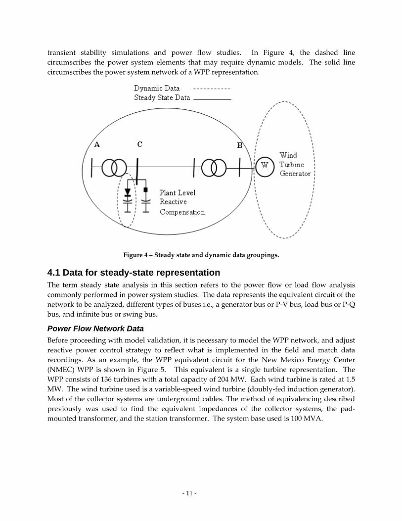
‐ 11 ‐
transient stability simulations and power flow studies. In Figure 4, the dashed line
circumscribes the power system elements that may require dynamic models. The solid line
circumscribes the power system network of a WPP representation.
Figure 4 – Steady state and dynamic data groupings.
4.1 Data for steady-state representation The term steady state analysis in this section refers to the power flow or load flow analysis
commonly performed in power system studies. The data represents the equivalent circuit of the
network to be analyzed, different types of buses i.e., a generator bus or P‐V bus, load bus or P‐Q
bus, and infinite bus or swing bus.
Power Flow Network Data
Before proceeding with model validation, it is necessary to model the WPP network, and adjust
reactive power control strategy to reflect what is implemented in the field and match data
recordings. As an example, the WPP equivalent circuit for the New Mexico Energy Center
(NMEC) WPP is shown in Figure 5. This equivalent is a single turbine representation. The
WPP consists of 136 turbines with a total capacity of 204 MW. Each wind turbine is rated at 1.5
MW. The wind turbine used is a variable‐speed wind turbine (doubly‐fed induction generator).
Most of the collector systems are underground cables. The method of equivalencing described
previously was used to find the equivalent impedances of the collector systems, the pad‐
mounted transformer, and the station transformer. The system base used is 100 MVA.
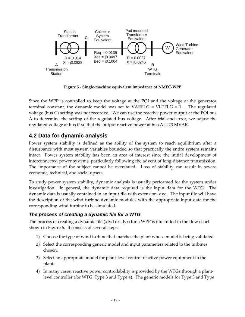
‐ 12 ‐
W
Pad-mounted Transformer Equivalent
Wind Turbine Generator Equivalent
Collector System
Equivalent
Station Transformer
BWTG
Terminals
A Transmission
Station
Req = 0.0135 Xes = j0.0497 Beq = j0.1004
C
R = 0.0027 X = j0.0245
R = 0.014 X = j0.0828
Figure 5 ‐ Single‐machine equivalent impedance of NMEC‐WPP
Since the WPP is controlled to keep the voltage at the POI and the voltage at the generator
terminal constant, the dynamic model was set to VARFLG = VLTFLG = 1. The regulated
voltage (bus C) setting was not recorded. We can use the reactive power output at the POI bus
A to determine the setting of the regulated bus voltage. After trial and error, we adjust the
regulated voltage at bus C so that the output reactive power at bus A is 23 MVAR.
4.2 Data for dynamic analysis Power system stability is defined as the ability of the system to reach equilibrium after a
disturbance with most system variables bounded so that practically the entire system remains
intact. Power system stability has been an area of interest since the initial development of
interconnected power systems, particularly following the advent of long‐distance transmission.
The importance of the subject cannot be overstated. Loss of stability can result in severe
economic, technical, and social upsets.
To study power system stability, dynamic analysis is usually performed for the system under
investigation. In general, the dynamic data required is the input data for the WTG. The
dynamic data is usually contained in an input file with extension .dyd. The input file will have
the description of the wind turbine dynamic modules with the appropriate input data for the
corresponding wind turbine to be simulated.
The process of creating a dynamic file for a WTG
The process of creating a dynamic file (.dyd or .dyr) for a WPP is illustrated in the flow chart
shown in Figure 6. It consists of several steps:
1) Choose the type of wind turbine that matches the plant whose model is being validated
2) Select the corresponding generic model and input parameters related to the turbines
chosen.
3) Select an appropriate model for plant‐level control reactive power equipment in the
plant.
4) In many cases, reactive power controllability is provided by the WTGs through a plant‐
level controller (for WTG Type 3 and Type 4). The generic models for Type 3 and Type
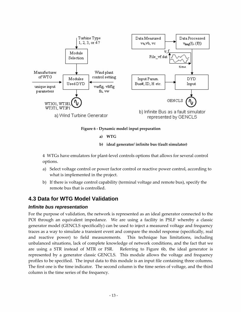
‐ 13 ‐
4 WTGs have emulators for plant‐level controls options that allows for several control
options.
a) Select voltage control or power factor control or reactive power control, according to
what is implemented in the project.
b) If there is voltage control capability (terminal voltage and remote bus), specify the
remote bus that is controlled.
4.3 Data for WTG Model Validation
Infinite bus representation
For the purpose of validation, the network is represented as an ideal generator connected to the
POI through an equivalent impedance. We are using a facility in PSLF whereby a classic
generator model (GENCLS specifically) can be used to inject a measured voltage and frequency
traces as a way to simulate a transient event and compare the model response (specifically, real
and reactive power) to field measurements. This technique has limitations, including
unbalanced situations, lack of complete knowledge of network conditions, and the fact that we
are using a STR instead of MTR or FSR. Referring to Figure 6b, the ideal generator is
represented by a generator classic GENCLS. This module allows the voltage and frequency
profiles to be specified. The input data to this module is an input file containing three columns.
The first one is the time indicator. The second column is the time series of voltage, and the third
column is the time series of the frequency.
Figure 6 ‐ Dynamic model input preparation
a) WTG
b) ideal generator/ infinite bus (fault simulator)
‐ 14 ‐
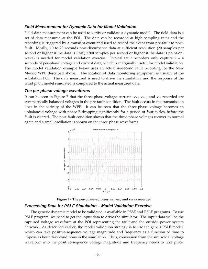
Field Measurement for Dynamic Data for Model Validation
Field‐data measurement can be used to verify or validate a dynamic model. The field data is a
set of data measured at the POI. The data can be recorded at high sampling rates and the
recording is triggered by a transient event and used to record the event from pre‐fault to post‐
fault. Ideally, 10 to 20 seconds post‐disturbance data at sufficient resolution (20 samples per
second or higher if the data is RMS; 7200 samples per second or higher if the data is point‐on‐
wave) is needed for model validation exercise. Typical fault recorders only capture 2 – 4
seconds of per‐phase voltage and current data, which is marginally useful for model validation.
The model validation example below uses an actual 4‐seecond fault recording for the New
Mexico WPP described above. The location of data monitoring equipment is usually at the
substation POI. The data measured is used to drive the simulation, and the response of the
wind plant model simulated is compared to the actual measured data.
The per phase voltage waveforms
It can be seen in Figure 7 that the three‐phase voltage currents van, vbn , and vcn recorded are
symmetrically balanced voltages in the pre‐fault condition. The fault occurs in the transmission
lines in the vicinity of the WPP. It can be seen that the three‐phase voltage becomes an
unbalanced voltage with phase B dropping significantly for a period of four cycles, before the
fault is cleared. The post‐fault condition shows that the three‐phase voltages recover to normal
again and a small oscillation is shown on the three‐phase waveforms.
0.9 0.92 0.94 0.96 0.98 1 1.02 1.04 1.06 1.08 1.1-4
-3
-2
-1
0
1
2
3
4x 10
5
Time (s)
Vol
tage
s (V
) -
Mea
sure
d
Three Phase Voltages - 1
Figure 7 ‐ The per‐phase‐voltages van, vbn , and vcn as recorded
Processing Data for PSLF Simulation – Model Validation Exercise
The generic dynamic model to be validated is available in PSSE and PSLF programs. To use
PSLF program, we need to get the input data to drive the simulator. The input data will be the
captured voltage waveform at the POI representing the fault and the outside power system
network. As described earlier, the model validation strategy is to use the gencls PSLF model,
which can take positive‐sequence voltage magnitude and frequency as a function of time to
impose as boundary conditions in the simulation. Thus, conversion from the sinusoidal voltage
waveform into the positive‐sequence voltage magnitude and frequency needs to take place.
‐ 15 ‐
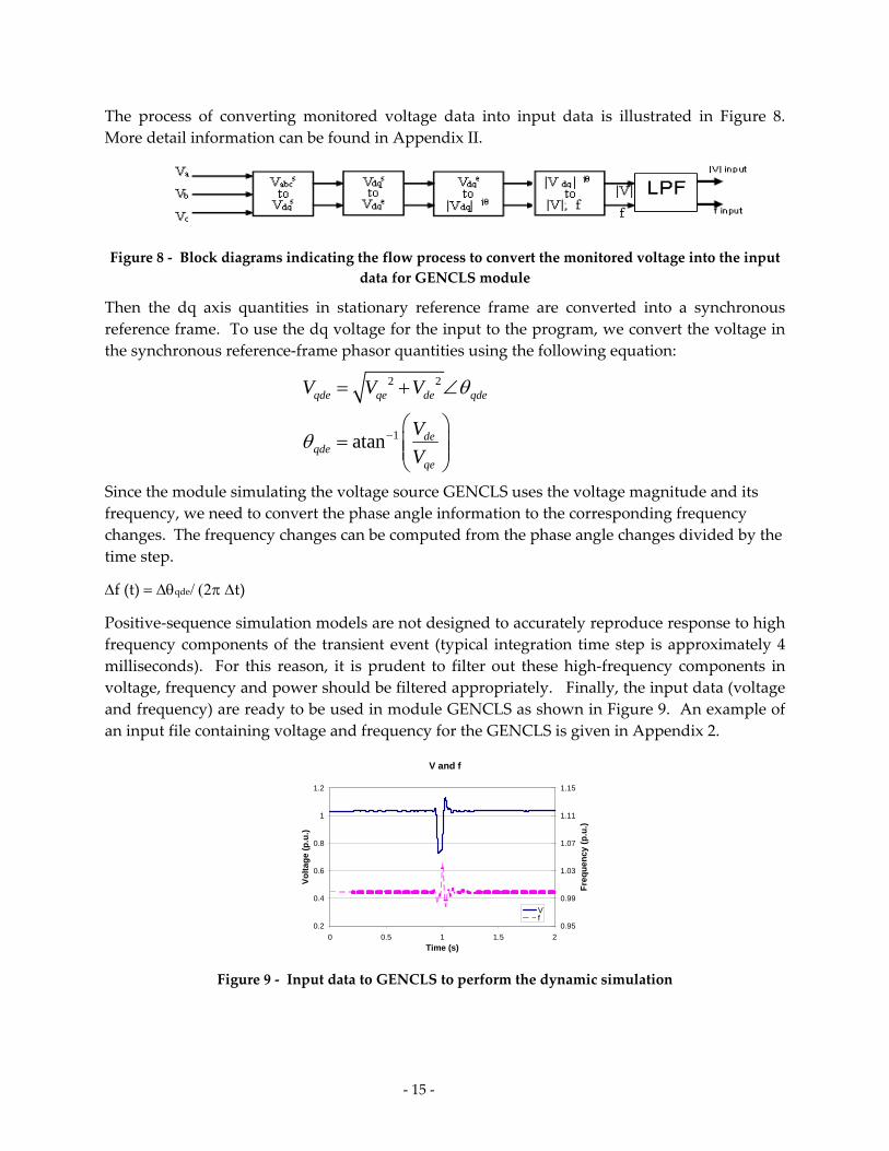
The process of converting monitored voltage data into input data is illustrated in Figure 8.
More detail information can be found in Appendix II.
Figure 8 ‐ Block diagrams indicating the flow process to convert the monitored voltage into the input
data for GENCLS module
Then the dq axis quantities in stationary reference frame are converted into a synchronous
reference frame. To use the dq voltage for the input to the program, we convert the voltage in
the synchronous reference‐frame phasor quantities using the following equation:
Since the module simulating the voltage source GENCLS uses the voltage magnitude and its
frequency, we need to convert the phase angle information to the corresponding frequency
changes. The frequency changes can be computed from the phase angle changes divided by the
time step.
f(t) qdet)
Positive‐sequence simulation models are not designed to accurately reproduce response to high
frequency components of the transient event (typical integration time step is approximately 4
milliseconds). For this reason, it is prudent to filter out these high‐frequency components in
voltage, frequency and power should be filtered appropriately. Finally, the input data (voltage
and frequency) are ready to be used in module GENCLS as shown in Figure 9. An example of
an input file containing voltage and frequency for the GENCLS is given in Appendix 2.
V and f
0.2
0.4
0.6
0.8
1
1.2
0 0.5 1 1.5 2
Time (s)
Vo
ltag
e (p
.u.)
0.95
0.99
1.03
1.07
1.11
1.15
Fre
qu
ency
(p
.u.)
Vf
Figure 9 ‐ Input data to GENCLS to perform the dynamic simulation
2 2
1atan
qde qe de qde
deqde
qe
V V V
V
V
‐ 16 ‐
5.0 Model Validation of Wind Turbine Generator WTG needs to be validated to ensure that the behavior of the dynamic model reflects the
behavior of the actual WTG. The wind turbine manufacturer usually develops a detailed model
of their turbine. This model contains detailed information considered proprietary by the
turbine manufacturer. The detailed model or manufacturer’s specific dynamic model is not
released to the public, thus, the WECC generic models developed in this project are the closest
models to the detailed model without revealing the proprietary information embedded in the
detailed model. The detail model is usually validated rigorously by the turbine manufacturer
against laboratory measurement within a controlled environment, and it is considered the best
representation of the wind turbine. Ideally, the WECC generic dynamic models should be
validated by turbine manufacturers against field measurements. In addition, it is not always
easy to get field data measurement from the WPP operator or owner. Thus, as an alternative to
using field measurement, you can compare the simulation of generic dynamic models to the
detailed models. A more detailed discussion on WTG Model Validation is presented in the
Appendix V of this report.
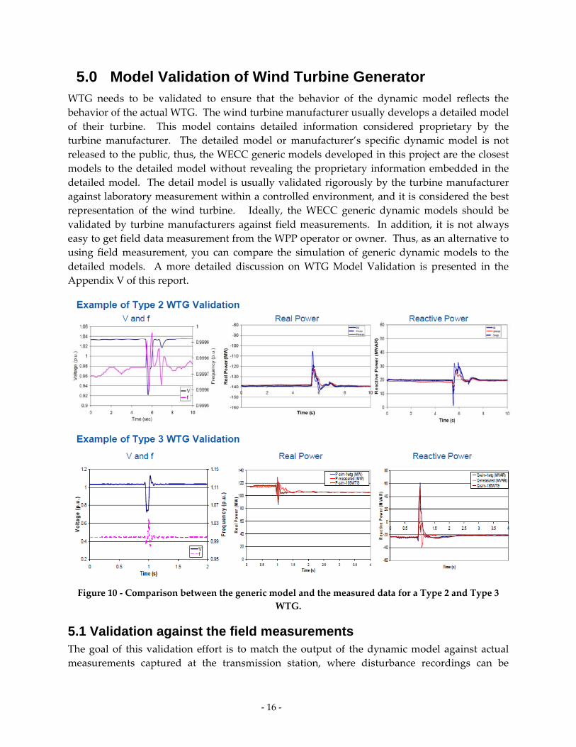
Figure 10 ‐ Comparison between the generic model and the measured data for a Type 2 and Type 3
WTG.
5.1 Validation against the field measurements The goal of this validation effort is to match the output of the dynamic model against actual
measurements captured at the transmission station, where disturbance recordings can be
‐ 17 ‐
obtained relatively easily. The disturbance used as an example in this report consists of a line‐
to‐ground fault in the vicinity of the transmission station, which resulted in a voltage transient
large enough to excite a significant dynamic response from the WPP, within the design
response capability of the generic model (up to about 5 Hz). Data before the fault occurred is
required to establish the pre‐disturbance power flow conditions that are used to initialize the
model. The disturbance record should extend several seconds after the contingency, consistent
with the time frame of interest of positive‐sequence transient stability analysis.
An example of validation using measured data is presented in Figure 10. The validation
requires measured data to be preprocessed. The measured three phase voltage recorded at
high speed is preprocessed to get the voltage magnitude and the frequency variation during the
fault. The voltage and frequency waveform are used to drive the simulation. The real and
reactive power outputs from the simulations are compared to the measured real and reactive
power.
5.2 Validation against the detailed (manufacturer specific) models In this subsection, the validation of generic dynamic models against the detailed models will be
presented. The generic dynamic models and the detailed models are simulated on the same
power system network, the same size of WPP, and using a prescribed fault event. The
simulation results from the two different dynamic models are then compared, and the
difference is used to tune the parameters of the generic models until the two dynamic models
generates the same output characteristics.
The dynamic models developed in this project are validated against the detailed dynamic
models by the model developers (Siemens Power Technologies International, and General
Electric). The model developers have signed a non‐disclosure agreement with the turbine
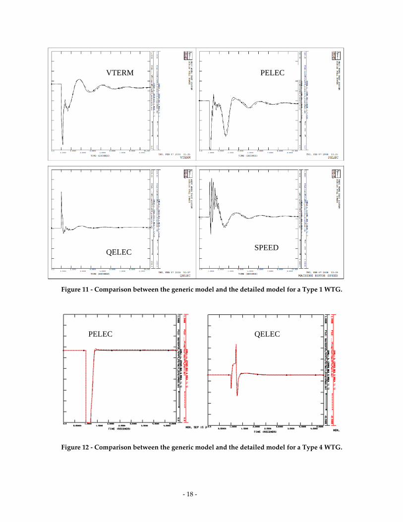
manufacturers to develop the detailed dynamic models. In Figure 11, a Type 1 WTG (induction
generator) from a specific turbine manufacturer is simulated. The output of the generic model
is compared to the output simulation of the Type 1 WTG detailed model.
The dashed line is the output simulation of the detailed model, and the solid line is the output
simulation of the generic model. It is shown that the terminal voltage VTERM, the real power
output PELEC, the reactive power QELEC and the rotor speed SPEED are all in agreement
between the generic model and the detailed model.
In Figure 12, the generic model of a Type 4 WTG is simulated and the simulation output is
compared against the detailed model of a Type 4 WTG when it is subjected to the same fault
event using the same power system network. The solid line represents the generic model and
the dashed line represents the detailed model. The real power PELEC and reactive power
QELEC traces are shown and the signals are almost identical. Note, that the Type 4 WTG is
modeled based on full power conversion that excludes the modeling of the mechanical dynamic
of the wind turbine.
‐ 18 ‐
Figure 11 ‐ Comparison between the generic model and the detailed model for a Type 1 WTG.
Figure 12 ‐ Comparison between the generic model and the detailed model for a Type 4 WTG.
SPEED QELEC
PELEC VTERM
PELEC QELEC
‐ 19 ‐
This project concluded with major accomplishments, including the completion of dynamic
models of four types of wind turbine generators on two major power system software platforms
(PSLF and PSSE), model validation of the four types of WTG dynamic models, and the WECC
modeling guides.
The result of this project is disseminated in many different ways. Currently, the Generic WTG
dynamic models (Type 1 – Type 4) developed by Siemens PTI and General Electric are presently
included in the software library of the PSSE and PSLF. In the past many power system planners
did not have any option to model WPP other than representing the WPP as negative loads or a
simple induction generator. The availability of the dynamic models of four types of WTG gives
the power system planners better options to represent the WPP correctly.
The WECC Power Flow Guide (2009) and WECC Dynamic Modeling Guide (to be completed in
2010) is accessible via the WECC website. This guide was developed by the Wind Generator
Modeling Group (WGMG) of the WECC. The Power Flow Guide is currently available from the
WECC website. The Dynamic Modeling Guide is currently being reviewed by the WGMG –
WECC and it will be made available from the WECC website.
Workshops/short‐courses/seminars on WTG dynamic modeling were presented at various
events sponsored by the IEEE, WECC, UWIG, IEC, and various universities.
Technical papers given at the IEEE, Wind Power, and other conferences on related topics: WPP
equivalencing, fault analysis of a wind plant, WTG dynamic model validation methodology,
power system stability, and short circuit behavior of WPP.
The list of technical papers and publications related to this project is listed in Appendix I. The
list of workshops, and short courses is given in Appendix II. An interim report describing the
equivalencing is included in Appendix III, an interim report describing the data collection is
given in the Appendix IV, and the interim report on dynamic model validation is given in the
Appendix V. Copies of WECC guides are given in the Appendices VI and VII.
6.0 Summary and Dissemination
‐ 20 ‐
The topic of dynamic modeling of WPP needs to be expanded. This continuation is necessary
because of the wind technology is changing rapidly − it requires continues model adaptation to
reflect the latest turbine implementation. Parameter sensitivities, identification, and tuning of
WTG dynamic models for different manufacturers are needed to help manufacturer derived
parameters for generic dynamic models representing their turbines.
In the next phase, it is also necessary to revise/improve dynamic models to include droop,
ramp‐limit, reserve management, preprogrammed frequency/inertial response, relay protection.
These capabilities will soon be implemented by turbine manufacturers and the existing models
may have to be upgraded to reflect new capabilities. Some of new turbine concepts may be
designed and installed in the near future. The new turbine concept should also be represented
especially if their presence in the power grid and the size are significant.
In order to facilitate the adaptation of generic models by other software vendors, we need to
support other software vendors (e.g., Powertech Lab, Inc., Operation Technology, Inc.) to
implement WTG dynamic models on their platforms.
The availability and use of future PMU data collected by different agencies (WECC, BPA,
ERCOT etc) will be accessed to validate dynamic models, predict WPP stability, design possible
new WPP controls and protection.
Finally, we need to interact with the IEEE, the IEC, WECC, and UWIG for standard/guide
development and public dissemination.
7.0 Future Plan
‐ 21 ‐
References
[1] E. Muljadi, C.P. Butterfield, A. Ellis, J. Mechenbier, J. Hocheimer, R. Young, N. Miller, R.
Delmerico, R. Zavadil, J.C. Smith, ”Equivalencing the Collector System of a Large Wind
Power Plant”, presented at the IEEE Power Engineering Society, Annual Conference,
Montreal, Quebec, June 12‐16, 2006.
[2] E. Muljadi, B. Parsons, ʺComparing Single and Multiple Turbine Representations in a
Wind Farm Simulation,ʺ presented at the European Wind Energy Conference (EWEC‐
2006), Athens, Greece, February 27 – March 2, 2006.
[3] N. W. Miller, J. J. Sanchez‐Gasca, W. W. Price, and R. W. Delmerico, “Dynamic modeling
of GE 1.5 and 3.6 MW wind turbine‐generators for stability simulations,” in Proc. 2003
IEEE Power Engineering Society General Meeting, pp. 1977–1983, June 2003
[4] J. O. G. Tande, E. Muljadi, O. Carlson, J. Pierik, A. Estanqueiro, P. Sørensen, M.
O’Malley, A. Mullane, O. Anaya‐Lara, and B. Lemstrom. Dynamic models of wind farms
for power system studies–status by IEA Wind R&D Annex 21,” European Wind Energy
Conference & Exhibition (EWEC), London, U.K., Nov. 22−25, 2004.
[5] T. Petru and T. Thiringer, ”Modeling of wind turbines for power system studies,” IEEE
Transactions on Power Systems, Volume 17, Issue 4, Nov. 2002, pp. 1132 – 1139.
[6] “Generic Type‐3 Wind Turbine‐Generator Model for Grid Studies”, Version 1.1,
prepared by WECC Wind Generator Modeling Group, September 14, 2006
[7] “WECC Wind Power Plant Power Flow Modeling Guide”, prepared by WECC Wind
Generator Modeling Group, November 2007
[8] P.C. Krause, Analysis of Electric Machinery, McGraw Hill Co. NY, 19862

‐ ‐ 22
Glossary .
The following acronyms are used in this report:
CEC California Energy Commission
CRPWM Current Regulated Pulse Width Modulation
DFAG Doubly Fed Asynchronous Generator
DFIG Doubly Fed Induction Generator
DOE Department of Energy
ERCOT Electric Reliability Council of Texas
FERC Federal Electric Regulatory Commission
FOC Flux Oriented Controller
FPL Florida Power and Light
FSR Full System Representation
IEC International Electrotechnical Commission
IEEE Institute of Electrical and Electronic Engineers
LVRT Low Voltage Ride Through
NMEC New Mexico Energy Center
NDA Non Disclosure Agreement
NEC National Electrical Code
NERC North American Electric Reliability Council
NREL National Renewable Energy Laboratory
PFC Power Factor Correction
PIER Public Interest Energy Research
PNM Public Service of New Mexico
POI Point of Interconnection
PSLF Positive Sequence Load Flow
PSSE Power System Simulator for Engineers
RAS Remedial Action Scheme

‐ ‐ 23
SVC Static VAr Compensator
TSR Tip Speed Radio
VAr Volt‐Ampere Reactive
WECC Western Electricity Coordinating Council
WGMG Wind Generator Modeling Group
WTG Wind Turbine Generator
WF Wind Farm
WPP Wind Power Plant
‐ ‐ I
Appendix I - List of Publications
1. R. Piwko, E. Camm, A. Ellis, E. Muljadi, R. Zavadil, R. Walling, M. O’Malley, G. Irwin, and, S. Saylors, “A Whirl of Activity”, the IEEE Power and Energy Magazine, November/December 2009
2. D. Burnham, S. Santoso, E. Muljadi, “Variable Rotor Resistance Control of Wind Turbine Generators,” presented at the IEEE Power Engineering Society, General Meeting, Calgary, Alberta, Canada, July 26-30, 2009.
3. M. Singh, K. Faria, S. Santoso, E. Muljadi “Validation and Analysis of Wind Power Plant Models using Short-Circuit Field Measurement Data,” presented at the IEEE Power Engineering Society, General Meeting, Calgary, Alberta, Canada, July 26-30, 2009.
4. E. Muljadi, T. Nguyen, M.A. Pai, “Transient Stability of the Grid with a Wind Power Plant,” to be presented at the IEEE Power System Conference and Exposition, Seattle, WA, Mar. 15-18, 2009.
5. E. Muljadi, T. Nguyen, M.A. Pai, “Impact of Wind Power Plants on Voltage and Transient Stability of Power Systems,” presented at the IEEE Energy2030 conference, Atlanta, Georgia, Nov. 17-18, 2008.
6. A. Ellis, E. Muljadi, ”Wind Power Plant Representation in Large-Scale Power Flow Simulations in WECC,” presented at the IEEE Power Engineering Society, General Meeting, Pittsburgh, PA, July 20-24, 2008.
7. E. Muljadi, A. Ellis,” Validation of Wind Power Plant Dynamic Models”, invited panel discussion presented at the IEEE Power Engineering Society, General Meeting, Pittsburgh, PA, July 20-24, 2008.
8. E. Muljadi, Z. Mills, R. Foster, J. Conto, A. Ellis, ” Fault Analysis at a Wind Power Plant for a One Year of Observation”, presented at the IEEE Power Engineering Society, General Meeting, Pittsburgh, PA, July 20-24, 2008.
9. E. Muljadi, S. Pasupulati, A. Ellis, D. Kosterov,” Method of Equivalencing for a Large Wind Power Plant with Multiple Turbine Representation”, presented at the IEEE Power Engineering Society, General Meeting, Pittsburgh, PA, July 20-24, 2008.
10. R. Zavadil, N. Miller, A. Ellis, E. Muljadi, E. Camm, and B. Kirby, “Queuing Up”, the IEEE Power and Energy Magazine, November/December 2007
11. E. Muljadi, C.P. Butterfield, B. Parsons, A. Ellis, ”Characteristics of Variable Speed Wind Turbines Under Normal and Fault Conditions”, presented at the IEEE Power Engineering Society, Annual Conference, Tampa, Florida, June 24-28, 2007.
12. M. Behnke, A. Ellis, Y. Kazachkov, T. McCoy, E. Muljadi, W. Price, J. Sanchez-Gasca “Development and Validation of WECC Variable Speed Wind Turbine Dynamic Models for Grid Integration Studies” presented at the Windpower 2007, WINDPOWER 2007 Conference & Exhibition, Los Angeles, CA, June 24-28, 2007.
13. E. Muljadi, C.P. Butterfield, B. Parsons, A. Ellis, “Effect of Variable Speed Wind Turbine Generator on Stability of a Weak Grid”, published in the IEEE Transactions on Energy Conversion, Vol. 22, No. 1, March 2007.
14. E. Muljadi, C.P. Butterfield, A. Ellis, J. Mechenbier, J. Hocheimer, R. Young, N. Miller, R. Delmerico, R. Zavadil, J.C. Smith, ”Equivalencing the Collector System of a Large Wind Power Plant”, presented at the IEEE Power Engineering Society, Annual Conference, Montreal, Quebec, June 12-16, 2006.

‐ ‐ II
Appendix II - List of Short Courses and Workshops
1) WECC – 2009 Generator Model Validation Workshop, held at Tristate Generator and Transmission Association, Westminster, CO May 18-19, 2009
2) WECC - 2009 Modeling Workshop for Planning Engineers, held at PG&E, San Francisco, CA, April 16-17 2009
3) IEEE Dynamic Performance of Wind Power Generation Task Force (DPWPGTF) “Tutorial on Wind Generation Modeling and Controls,” IEEE PSCE Conference, Seattle, WA, USA – March 2009
4) Tutorial “Wind Energy Boot Camp” organized by New Mexico State University, PNM, and NREL at Albuquerque, NM, Nov 12-14, 2008
5) IEEE Dynamic Performance of Wind Power Generation Task Force (DPWPGTF) “Tutorial on Wind Generation Modeling and Controls,” IEEE PES General Meeting, Pittsburgh, PA, USA – July, 2008
6) “WECC Wind Generator Modeling Project “, Policy Advisory Committee, California Energy Commission (CEC), Irwindale, CA, 8/20/2007 and Kick off meeting for the, Los Angeles, CA, 8/21/2007
7) “Wind Generator Modeling”, CEC-PIER-TRP Technical Advisory Committee Meeting, Sacramento, CA, October 3, 2006
8) “Equivalencing Large Wind Power Plant”, WECC 2006 Modeling Workshop, Las Vegas, NV, June 14-15, 2006