voltage recovery criterion - wecc
TRANSCRIPT
© California ISO 2019 – CAISO Public© California ISO 2019 – CAISO Public
Irina Green, Senior Advisor, Regional Transmission,California ISO
WECC Modeling and Validation Subcommittee Workshop
September 18, 2020
Transient Voltage Recovery Criterion -
© California ISO 2019 – CAISO Public
NERC TPL 001-4 Standard - Transmission System Planning Performance Requirements
Performance requirements: No generating unit shall pull out of synchronism for P1. For P2 - P7: When a generator pulls out of synchronism there
should be no additional transmission or generation tripping For P1 - P7: Power oscillations shall exhibit acceptable
damping R5. Each Transmission Planner and Planning Coordinator shall
have criteria for acceptable System steady state voltage limits, post-Contingency voltage deviations, and the transient voltage response for its System. For transient voltage response, the criteria shall at a minimum, specify a low voltage level and a maximum length of time that transient voltages may remain below that level
No numbers in the Standard of what levels and times it should bePage 2
© California ISO 2019 – CAISO Public
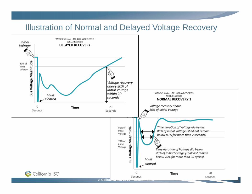
TPL-001-WECC-CRT-3.2.1.3. Following fault clearing, the voltage shall recover to 80% of the pre-contingency voltage within 20 seconds of the initiating event for all P1 through P7 events, for each applicable BES bus serving load.
1.4. Following fault clearing and voltage recovery above 80%, voltage at each applicable BES bus serving load shall neither dip below 70% of pre-contingency voltage for more than 30 cycles nor remain below 80% of pre-contingency voltage for more than two seconds, for all P1 through P7 events.
These requirements apply to the BES Facilities and do not apply to the buses at the low sides of distribution transformers and at the ends of the feeders that are added to the system model by composite load model.
Page 3
© California ISO 2019 – CAISO Public
Illustration of Normal and Delayed Voltage Recovery
•
Page 4
© California ISO 2019 – CAISO Public
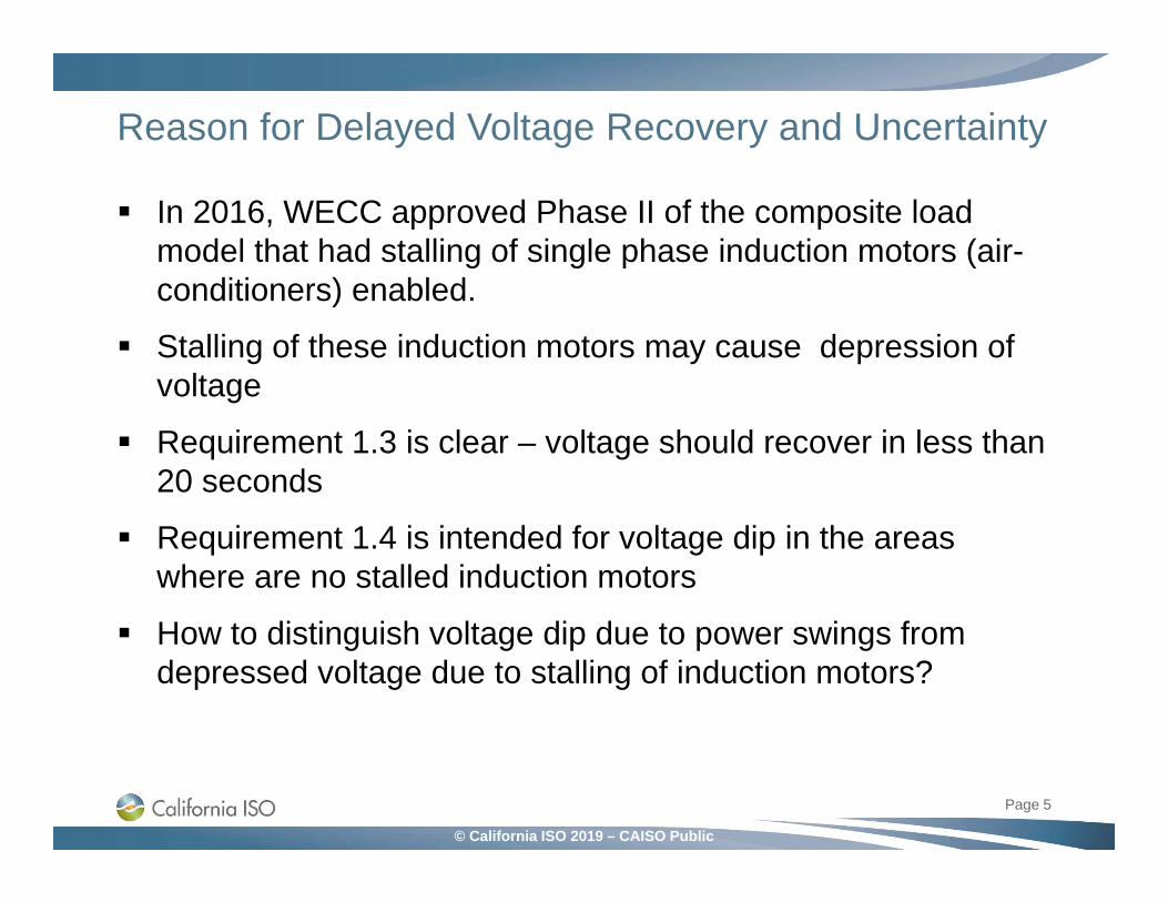
Reason for Delayed Voltage Recovery and Uncertainty
In 2016, WECC approved Phase II of the composite load model that had stalling of single phase induction motors (air-conditioners) enabled.
Stalling of these induction motors may cause depression of voltage
Requirement 1.3 is clear – voltage should recover in less than 20 seconds
Requirement 1.4 is intended for voltage dip in the areas where are no stalled induction motors
How to distinguish voltage dip due to power swings from depressed voltage due to stalling of induction motors?
Page 5
© California ISO 2019 – CAISO Public
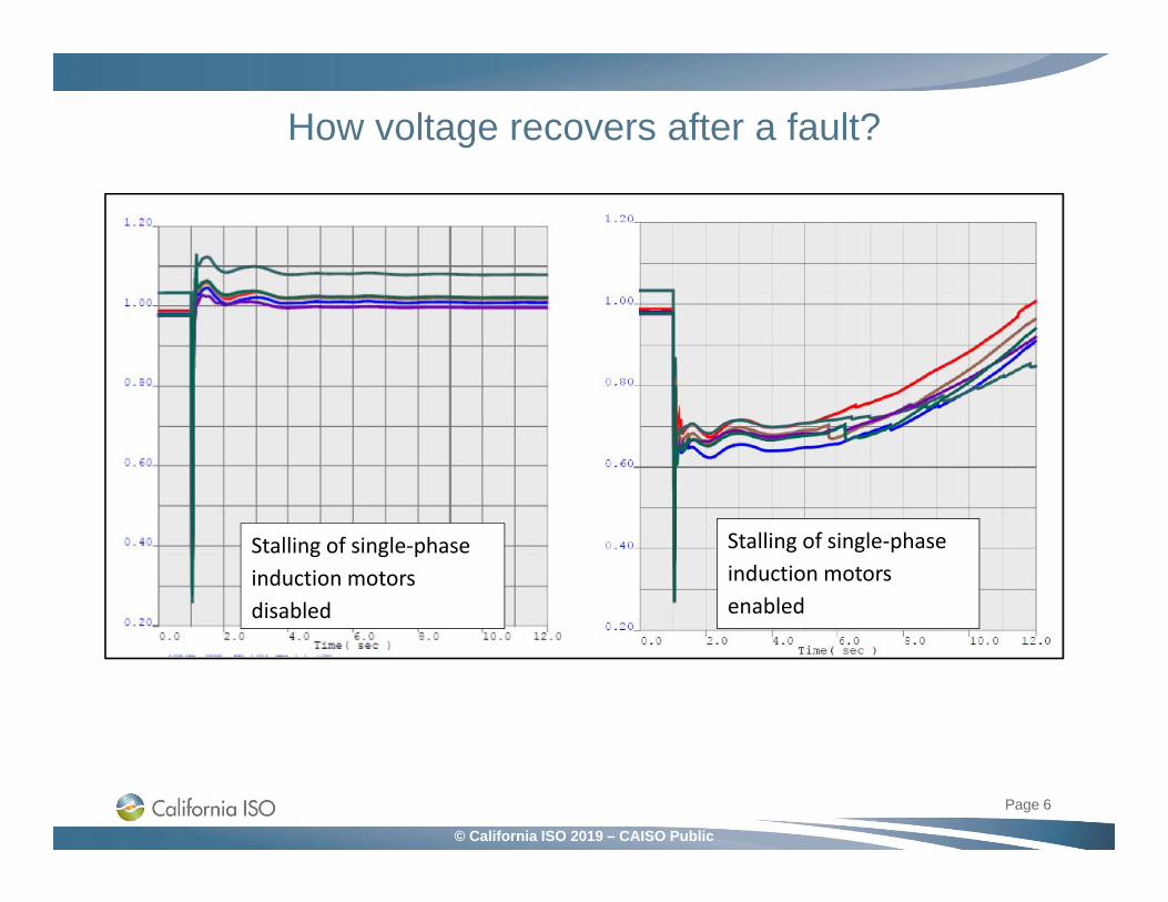
How voltage recovers after a fault?
Page 6
Stalling of single‐phase induction motors disabled
Stalling of single‐phase induction motors enabled
© California ISO 2019 – CAISO Public
Issues with Staling of Induction Motors
From the study results it may be problematic to distinguish whether voltage dips were caused by power swings or by stalling of single-phase induction motors following faults.
With delayed voltage recovery, voltage not necessarily stays below 80% of the initial pre-contingency voltage. In many cases, voltage recovers above 80% right after the fault and then falls below that due to stalling of induction motors.
Page 7
© California ISO 2019 – CAISO Public
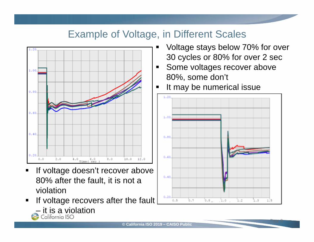
Example of Voltage, in Different Scales•
Page 8
Voltage stays below 70% for over 30 cycles or 80% for over 2 sec
Some voltages recover above 80%, some don’t
It may be numerical issue
If voltage doesn’t recover above 80% after the fault, it is not a violation
If voltage recovers after the fault – it is a violation
© California ISO 2019 – CAISO Public
Should it count as a criteria violation?
None of the buses in this example had voltage dips caused by power swings.
The observed transient voltage performance was due to stalling of induction motors, even if the study results indicated criteria violations caused by unacceptable voltage dips for the buses where voltage recovered to above 80% right after the fault.
More examples?
Page 9
© California ISO 2019 – CAISO Public
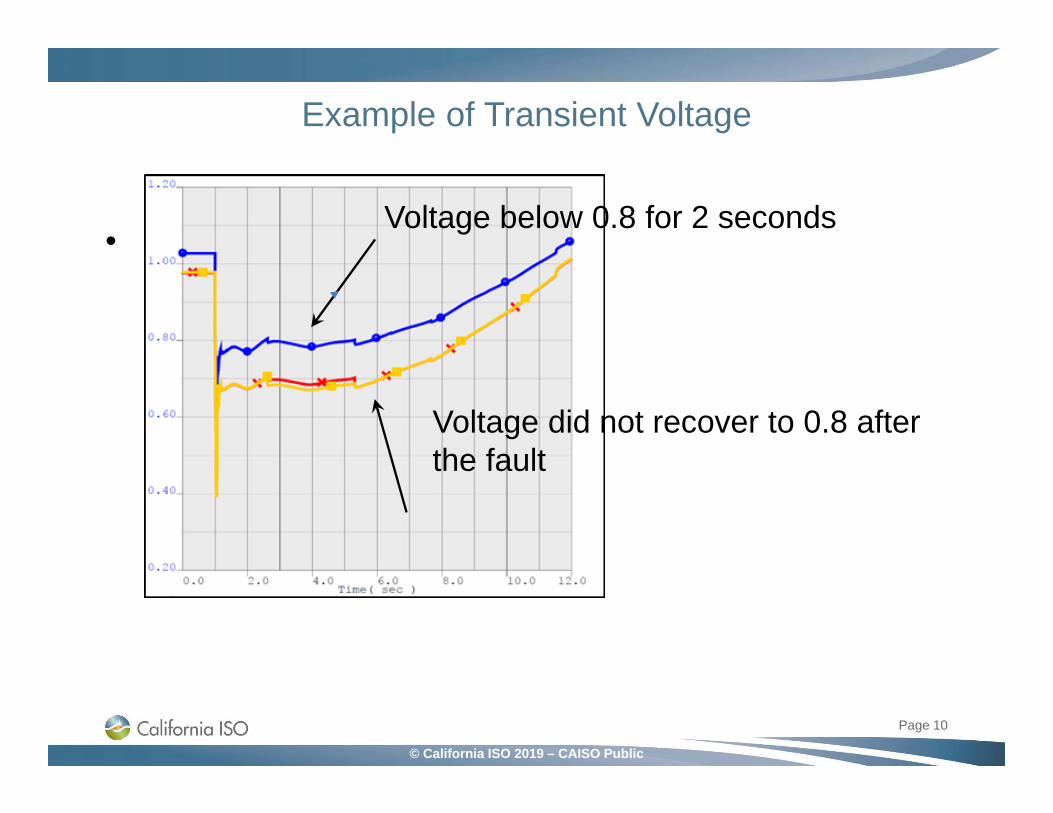
Example of Transient Voltage
•
Page 10
Voltage below 0.8 for 2 seconds
Voltage did not recover to 0.8 after the fault
© California ISO 2019 – CAISO Public
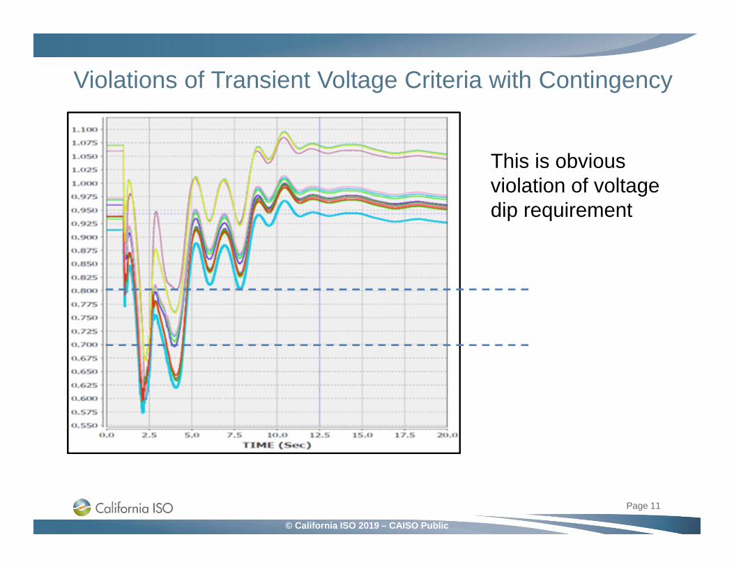
Violations of Transient Voltage Criteria with Contingency
•
Page 11
This is obvious violation of voltage dip requirement
© California ISO 2019 – CAISO Public
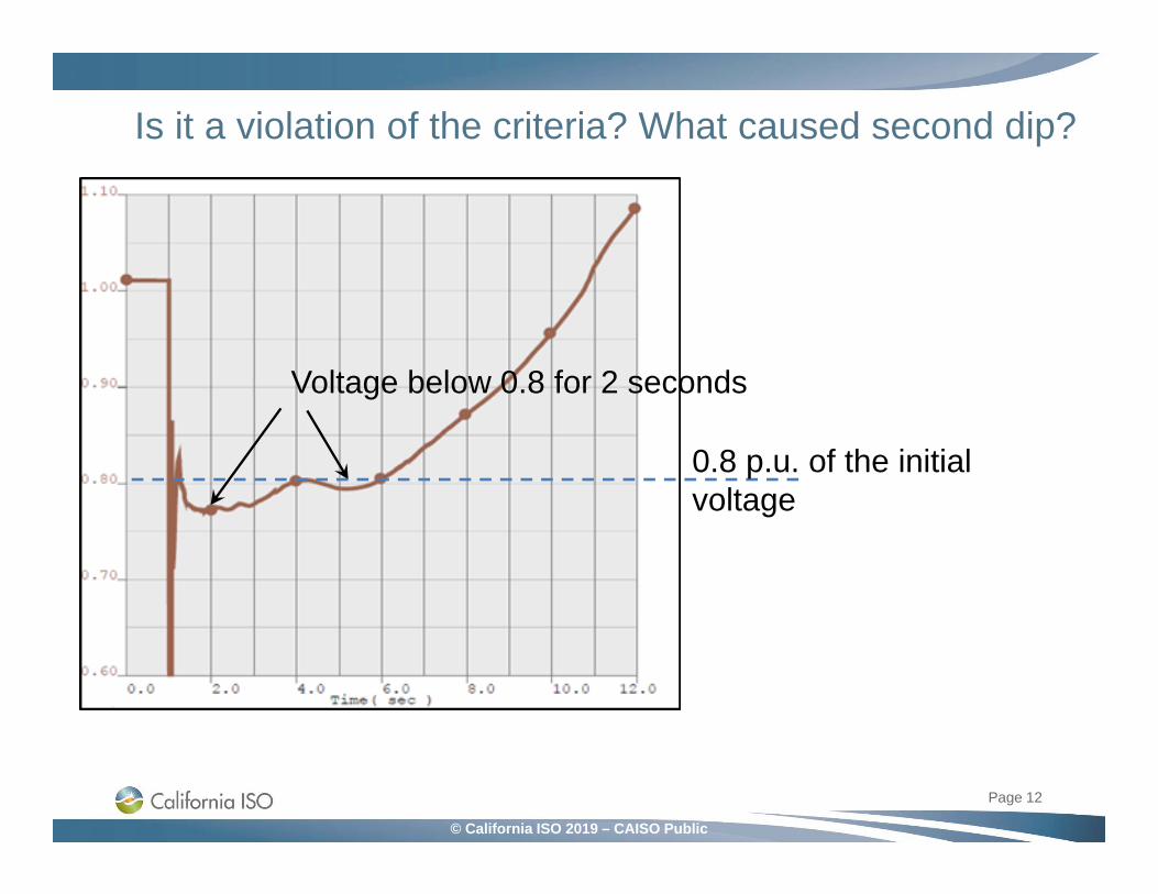
Is it a violation of the criteria? What caused second dip?
•
Page 12
Voltage below 0.8 for 2 seconds
0.8 p.u. of the initial voltage
© California ISO 2019 – CAISO Public
WECC-CRT-3.2 Criteria – Voltage Recovery
For the faults not resulting in motor stalling, the intention of the criteria was to specify a voltage dip that would give a reasonable expectation of loss of load subsequent to the initial recovery above 80% after fault clearing.
However, from these examples loss of load is not clear.
There may be different interpretations of Requirement 1.4 by different entities. What is considered to be a criteria violation by one company, may not be considered a violation, but just an example of the slow voltage recovery which is within the criteria, by another one.
May lead to additional investments in fixing voltage dip, which are actually unnecessary, or to not implementing necessary upgrades.
Page 13

© California ISO 2019 – CAISO Public
Questions to Ask How does meeting this criteria help BES reliability?
Is the criteria a proxy for early-warning of BES instability? If so, which one– voltage, angular, both?
Is the criteria intended to flag unacceptable FIDVR when applied at load buses? Then, what’s the adverse reliability impact of unacceptable FIDVR?
Is it loss of load? But, loss of voltage-sensitive load is not a non-consequential load loss and is allowed by the NERC TPL criteria
How does FIDVR driven load loss equate to unacceptable system performance specified in NERC TPL 001-4 Table 1? If we cannot map the FIDVR load loss to Table 1 performance, then how is unacceptable FIDVR (and hence transient voltage criteria) a useful metric for BES reliability?
Page 14
© California ISO 2019 – CAISO Public
Does Criterion need to be re-written? If yes, how? Specify the duration of time when voltage should stay above
80% after the fault prior to decreasing. Add the magnitude of voltage dip from the time when it starts
that is considered to be the criteria violation. Add limitations on how much load may be lost, or to what
magnitude voltage may raise after the transient period. Will criterion improve if this is added?
Even if the Criteria may be confusing, it doesn’t need to be re-written
It is up to TP and PC to decide how to apply the Criteria to their systems
In each specific case, engineering judgement needs to be used.
Page 15
Conclusions after Discussions with WECC

© California ISO 2019 – CAISO Public
Application of the WECC Transient Recovery Criteria at the California ISO
Criteria is applied only to the BES system. Distribution feeders and fictitious load buses created by composite load model are excluded.
We distinguish between voltage dip and slow voltage recovery based on the output channel plots
Page 16
230 kV Bus
End of the feeder
Recovered in less than 20 secondsVoltage dip is not a violation
115 kV bus

© California ISO 2019 – CAISO Public
QUESTIONS?COMMENTS?
SUGGESTIONS?
Please send your comments to Irina [email protected]
Page 17