fault tolerant free gait and footstep planning for hexapod
TRANSCRIPT

Fault Tolerant Free Gait and Footstep Planning forHexapod Robot Based on Monte-Carlo Tree
Liang Ding1,*, Peng Xu1,*, Haibo Gao1, Zhikai Wang1, Ruyi Zhou1, Zhaopei Gong1, and Guangjun Liu2
1State Key Laboratory of Robotics and Systems, Harbin Institute of Technology, Harbin 150001, China2 Department of Aerospace Engineering, Ryerson University, Toronto, ON M5B 2K3, Canada
*These authors contributed equally to this work. Contact Email: [email protected]
Abstract—Legged robots can pass through complex field en-vironments by selecting gaits and discrete footholds carefully.Traditional methods plan gait and foothold separately and treatthem as the single-step optimal process. However, such processingcauses its poor passability in a sparse foothold environment.This paper novelly proposes a coordinative planning method forhexapod robots that regards the planning of gait and footholdas a sequence optimization problem with the consideration ofdealing with the harshness of the environment as leg fault. TheMonte Carlo tree search algorithm(MCTS) is used to optimizethe entire sequence. Two methods, FastMCTS, and SlidingMCTSare proposed to solve some defeats of the standard MCTSapplicating in the field of legged robot planning. The proposedplanning algorithm combines the fault-tolerant gait method toimprove the passability of the algorithm. Finally, compared withother planning methods, experiments on terrains with differentdensities of footholds and artificially-designed challenging terrainare carried out to verify our methods. All results show that theproposed method dramatically improves the hexapod robotâAZsability to pass through sparse footholds environment.
I. INTRODUCTION
Legged robots can select discrete footholds to cross variouscomplicated terrain, which leads them to execute motor taskson fields such as field rescue and planetary exploration inthe future. The hexapod robots that have higher stabilityand superior load capacity than biped robots and quadrupedrobots are widely used[1][2][3]. Still, the planning of gaitand foothold for such robots is more complicated with morelegs. The traditional planning framework plans gait first, andthen plan the foothold of the swing leg according to theterrain[4][5][6]. The two steps are independent of each other,making optimal decisions based on corresponding rules orevaluation functions. However, in harsh environments, tra-ditional planning frameworks can easily cause robots to betrapped because such planning methods make decisions arebased on only the current environment and the state of therobot, and it does not consider the following situation. Inthis paper, We focus on improving the robotâAZs ability topass in a sparse foothold environment by selecting appropriatefootholds and gait.
Gait is usually used to express the walking mode of thelegged robot. The choice of gait can affect the robotâAZs for-ward speed, stability, and passability. Classifying by whetherthe gait changes periodically, there are two modes, includingperiodic gait and aperiodic gait. According to different plan-
Fig. 1. Establishing Monte Carlo tree for walking planning of hexapodrobot in sparse foothold environment. Each node represents a state of therobot. When the constructed node reaches the target position, the entire searchalgorithm ends. The dotted arrows in the figure indicate omitted parts, andthe whole tree in the figure is a schematic structure and is not complete.
ning methods, gait can be divided into the rule-based methodand CPG method. For rule-based method, when walking ina periodic gait, assuming that all footsteps are valid, leggedrobots move forward in a fixed swing sequence, which isusually taken as 3+3 tripod gait, 4+2 quadruped gait or 5+1wave gait for hexapod robots[7]. Because these gaits arequickly to use, they are widely used by researchers[8][9][10].When the terrain is rugged or some areas are unsupportable,the legged robot needs to change its gait according to theterrain information and its state information, then generatea sequence of gaits with an irregular order. This kind ofaperiodic gait is called as free gait. The free gait proposedby Kugushev and Jaroshevskij[11] in 1975 is characterized byaperiodic, irregular, asymmetric, and terrain adapt. For freegait, the order of legs changes in a non-fixed but flexiblemanner depending on the trajectory, terrain properties andmotion state. In irregular terrain, this gait type is more flexibleand adaptable than periodic and regular gait. A large numberof free gaits for quadruped or hexapod robots have beendeveloped so far[12][13][14].
Another biologically-inspired gait generation method is theCPG method. From the perspective of imitating the biologicalgait rhythm control, the CPG gait planning method regardseach foot of the robot as a neuron and realizes the walking
arX
iv:2
006.
0755
0v2
[cs
.RO
] 1
6 Ju
n 20
20

of the robot by periodically triggering the movement of eachfoot. Shik et al.[15] proposed that the rhythmic movementof animals was controlled by a central pattern generator(CPG). Since then, a large number of scholars have carriedout studies on CPG to planning the gait for legged robots[16][17][18]. CPG gait mainly controls the movement of thelegs through an oscillator, without any feedback, and it is easyto achieve smooth transitions between gait. However, when theenvironment becomes complicated, if a sequence of legs iswrong, the whole CPG model will collapse. Therefore somescholars combined it with the reflex model to improve theenvironmental adaptability of the CPG model. For example,Santos[19] used the reflex model to provide reflection signalsand realized the dynamic regulation of the movement rhythmby modifying the CPG model parameters. Mustafa SuphiErden[20] used the reinforcement learning method to conductthe CPG network and reflection model’s structural training.
The selection of foothold is often carried out after gait plan-ning. For foothold planning method, Expert threshold methodis commonly used by scholars to select the footholds accordingto the features such as the roughness of the terrain, the amountof slope, the degree of proximity to the edge, the amountof slip and the height variance [21][22]. Kolter[23] used ahierarchical apprenticeship learning algorithm to select thefootholds. It still used the human expert experience to adjustthe cost function weights. Besides, Kalakrishnan[24] proposeda more elaborate method, using geometric terrain templatelearning to extract useful landing features, and the terraintemplate was completed by human teaching. [25] establisheda 2.5D map through 2D lidar, and propose a foothold selectionalgorithm, which employs unsupervised learning to create anadaptive decision surface. The robot can learn from realisticsimulations, and no prior expert-given rules or parameters areused. The above methods only consider the environmentalcharacteristics where the robot is. When the environmentbecomes extremely harsh, if a leg has no foothold, no relatedwork has been found to solve it. Our method is that theproblem can be avoided by sequence optimization, or a fault-tolerant gait method can be combined to deal with it.
Inspired by well-known artificial intelligence caseAlphaGo[26][27], Mente-Carlo Tree Search(MCTS)[28] isan excellent method to find an optimal decision to solve thesequence optimization problem. Monte Carlo methods have along history within numerical algorithms and have also hadsignificant success in various AI game-playing algorithms.Recently, Monte Carlo trees have been used in unmannedvehicles and robots. For example, [29] adopted the MCTSalgorithm to consider interactions between different vehiclesto plan cooperative motion plans. [30] combines QMDP,unscented transform, and MCTS to establish an autonomousdriving decision framework. For the first time, MCTS wasused to solve the planning problem of legged robots[31].This work mainly demonstrates the application of the MCTSmethod to the field of blind walking of biped robots, whichrequires robots to avoid obstacles on the platform ground.
For other sequence optimization methods, there are several
works. [32] combines contact search, and trajectory generationinto a Mixed-Integer Convex Optimization problem at thesame time, a sequence optimization method was formed. [33]combines a graph-based high-level path planner with low-levelsampling-based optimization of climbing to plan a footstepsequence. In the work of [34], the quadruped robot Anymalwas trained to walk in complex environments through DeepReinforcement Learning. They trained the perceptual planninglayer and control layer into two networks. The perceptualplanning layer strategy can generate basic motion sequencesthat lead the robot to the target position. The method issimilar to the sequence optimization problem we emphasized,but they do not focus on the comparison of such passabilitywith traditional methods. Whether the superiority in the sparsefoothold environment can be guaranteed is not carefully ex-plained. Besides, the above optimization work is carried outon quadruped or biped robots. Hexapod robots have a richercombination of gait and foothold, and no related work hasbeen described yet.
In this article, we mainly discuss how to plan gait andfoothold to improve the robot’s ability to pass in sparsefoothold. The main contributions of this paper lie in:
1) The gait generation and foothold planning are solved asa sequence optimization problem, and the Monte Carlo TreeSearch algorithm is used to optimize the decision sequence.Method couples gait generation and foothold selection.
2) Treat the legs without candidate foothold as faulty legs,and combine the idea of fault-tolerant gait with our planningmethod to improve the passing ability of hexapod robotsin extreme environments. In addition, a free fault-tolerantgait expert planning method considering environmental faulttolerance is also proposed.
3) Two methods, Fast-MCTS, and Sliding-MCTS are pro-posed. The Fast-MCTS method has higher pass performanceand faster search speed. Sliding-MCTS has an effective bal-ance between optimization and search time.
4) Compare the indicators of traditional methods and se-quence optimization methods in the sparse foothold environ-ment. The advantages and disadvantages of different methodsare explained.
II. FAULT TOLERANT FREE GAIT PLANNING
To explain the method better, first define and explain therelevant indicators for gait and foothold planning of hexapodrobot.
A. Notation and Definition
Definition:Support polygonThe support polygon is a convex polygon formed by the
projection points of the robot’s supporting feet positions fallingon the horizontal plane. Support polygons are often usedto measure the stability of legged robot. If the horizontalprojection of robot’s COG falls within the supporting polygon,then the robot is statically stable. When robot moves, if thecenter of gravity is too close to the edge of the supportingpolygon, the stability of robot is poor. In order to reduce the

1KM2KM
3KM
4KM
5KM
6KM
BM
AACOG
4KM
5KM
6KM
1KM
3KM
2KM
BM
AA
COG
Fig. 2. Parameter definition of hexapod robot planning
critical stability process during the planning process, this paperuses the centroid as center to reduce the support polygon, Asshown in Figure 3(a), the polygon formed by the solid lineis the original supporting polygon, and the polygon formedby the broken line is the reduced supporting polygon. (xc, yc)represents the coordinate of centroid, and (xi, yi) denotes thecoordinate of one support leg’s feet position. The formula forcalculating centroid coordinates (xc, yc) is as follows:
xc =1
6A
n∑i=1
(xi + xi+1)(xi · yi+1 − xi+1 · yi) (1)
yc =1
6A
n∑i=1
(yi + yi+1)(xi · yi+1 − xi+1 · yi) (2)
Where A represents the area of the original supporting poly-gon.
A =1
2
n∑i=1
(xi · yi+1 − xi+1 · yi) (3)
Finally, according to the calculated centroid position anda constant stability margin BM0, the support polygon isreduced.
0BM
Coxa link
Thigh link
Shank link
(a) (b)
3 3( , )x y
i
sz
i
sxi
sy2 2( , )x y1 1( , )x y
5 5( , )x y
4 4( , )x y
( , )c cx y
legi
Moving direction
iKM
Fig. 3. (a) Support polygons shrink in proportion. (b) Simplified one-legworkspace.
Definition:Single Leg WorkspaceThe workspace of a single leg is simplified into a
fan-shaped space, as shown in Figure 3(b). The sectoris defined in the single-leg workspace coordinate system∑
si(Osi − x
(i)s y
(i)s z
(i)s ) , Coordinate system
∑si
is fixed to
the robot.
Definition:Support Statecf := [s1, s2, s3, s4, s5, s6] ∈ R1×6 is a vector indicating
the support state of hexapod moving to the next step. If leg iis a support leg, the value of si is 0, if the leg i is a swingleg, the value of si is 1.
Definition:Fault LegIf the environment is very complicated, which results in
that some legs do not have effective footholds to choosefrom. Then at this time, the leg with no alternative footholdis defined as the fault leg. For possible physical damages toa leg, we also treat it as a fault leg.
Definition:Leg Fault StatetF := [f1, f2, f3, f4, f5, f6] ∈ R1×6 represents the leg fault
state vector of the six-legged robot from the current state tothe next state. If leg i is a fault leg, the value of fi is 1. Ifleg i is a normal leg, the value of fi is 0. Note that if a legis the fault leg, it must not be a support leg.
Definition:Hexapod StateΦ :=< W
BR, WB r , cF , tF ,
WF r > is defined as the state
of hexapod robot. Where WBR ∈ SO3 is the rotation matrix
representing the attitude of the base w.r.t W frame. WB r ∈ R3
is the target position of robot’s COG in next step w.r.t Wframe. cF is the support state vector of the robot from thecurrent state to the next state. tF represents the leg fault statevector of the hexapod robot from the current state to thenext state. W
F r ∈ R3 is the target position of ith foot in nextstep(foothold position) w.r.t W frame.
Definition:Static MarginStability margin, SM , also known as the absolute static
stability margin, is the smallest distance from the verticalprojection of the COG(centre of gravity) on a horizontalplane to the sides of the support polygon formed by joiningthe projections of the footholds on the same horizontal plane,as is shown in Figure 2.
Definition:Reduced Kinematic MarginAs shown in Figure 3(b), the reduced kinematic margin,
KMi, represents the distance that the ith foot position movesin the opposite direction of the robot motion and reaches theboundary of the working space of leg i.
Definition:Maximum Advance Amount Based COGThe maximum advance amount based support area is the
maximum distance which the hexapod can moves in theforward direction in the condition that the COG canâAZtexceed the support area. It is defined as AA.
Definition:Maximum Step LengthThe maximum step length is the maximum distance that
hexapod can move as long as in the forward direction. It

Support status
selection
engthstepL
Step length
planningFoothold selection Trajectory planning
Fig. 4. Traditional legged robot motion planning framework.
depends on the hexapodâAZs state and is defined as:
MSL = min(KMi, AA)(i = 1, 2, 3...6) (4)
Definition:Support State ListSupport State List represents the maximum allowable set
of support states for the robot. Each leg of a legged robothas support state and swing state two states. The combinationof different leg states constitutes the support state of therobot. For a hexapod robot, there are 26, 64 possible supportstates. To ensure static stability, the number of supportinglegs should not be less than 3. After excluding these supportstates, only 42 alternative support states remain, as shown inTable I.When planning the next support state with a specifiedsix-footed robot state, the supportable state table is usedas an initial candidate state table for screening, and a newcandidate support state table that meets the requirements isfinally obtained.
Definition:Solution SequenceThe solution sequence represents the state sequence of the
robot from the current position to the target position. Definethe solution sequence as Ψ = {Φ1,Φ2...Φk}, Indicates thatthe robot needs to go through k state transitions to reach itsdestination.
B. Fault Tolerant Free Gait Method
(1) Traditional free gait planning piplineThe free fault-tolerant gait proposed in this section is based
on the traditional expert planning process. Traditional expertplanning pipeline is shown in Figure 4. First, plan the supportstate cF (gait). Second, according to the selected gait, the steplength of the robot is determined. Third, for the swing legsdetermined by step 1, the optimal footholds W
F r are selectedin their working space. Finally, According to the terminal robotstate Φk+1, current robot state Φk and environmental obstacleinformation planned in the above steps, the robot body andleg trajectory are generated.
To improve the stability and passiblity, the traditionalplanning framework also contains posture optimization step.This article focuses on gait and foothold planning, so wetemporarily ignore the body posture optimization process,which will not affect the propose of our method.
(2) Fault tolerant gait planning
TABLE ISUPPORT STATE LIST
Num Support State Num Support State1 0 0 0 1 1 1 22 1 0 1 0 1 02 0 0 1 0 1 1 23 1 0 1 0 1 13 0 0 1 1 0 1 24 1 0 1 1 0 04 0 0 1 1 1 0 25 1 0 1 1 0 15 0 0 1 1 1 1 26 1 0 1 1 1 06 0 1 0 0 1 1 27 1 0 1 1 1 17 0 1 0 1 0 1 28 1 1 0 0 0 18 0 1 0 1 1 0 29 1 1 0 0 1 09 0 1 0 1 1 1 30 1 1 0 0 1 1
10 0 1 1 0 0 1 31 1 1 0 1 0 011 0 1 1 0 1 0 32 1 1 0 1 0 112 0 1 1 0 1 1 33 1 1 0 1 1 013 0 1 1 1 0 0 34 1 1 0 1 1 114 0 1 1 1 0 1 35 1 1 1 0 0 015 0 1 1 1 1 0 36 1 1 1 0 0 116 0 1 1 1 1 1 37 1 1 1 0 1 017 1 0 0 0 1 1 38 1 1 1 0 1 118 1 0 0 1 0 1 39 1 1 1 1 0 019 1 0 0 1 1 0 40 1 1 1 1 0 120 1 0 0 1 1 1 41 1 1 1 1 1 021 1 0 1 0 0 1 42 1 1 1 1 1 1
Fault-tolerant gait refers to the gait that occurs when eachleg of the robot cannot work correctly due to hardware reasons,such as driver failure, motor failure, legs locked. Because thehexapod robot has more number of legs, the robot can stillwork in the condition of static stability even if one or two legscannot run. As shown in Figure 5, In the wild environment,there are situations where it is impossible to guarantee thatall legs can fall, such as local slippage, subsidence, or suddennarrowing of the terrain. Therefore, referring to the idea offault tolerance, the above situation is also regarded as atemporary leg fault. In a word, we define the leg withoutcandidate foothold or having physical damages as the faultleg. Combined the idea of dynamic fault tolerance, the robothas a stronger ability to pass and adapt to the environment.When the faults occur, the hexapod can continue to walk byraising the fault legs up. When the fault is eliminated, therobot restores the function of the faulty leg.
(3) Planning Method
The gait planning in the article relies on heuristic rulesbecause these rules are the only ones that can plan leg motionsaccurately and guarantee stability using physical laws. Thetask of free gait is to choose which leg is the swing leg andwhich leg is the support leg aperiodic during the walk.

Soft
Fig. 5. Schematic diagram of environmental fault-tolerant terrain.
1) Support State Planning: In most cases, there are threecriteria to choose support state.
One criterion to be taken into account in support stateplanning is the maximization of the stability margin. It is saferfor the robot to have a larger static stability margin duringwalking.
Second, maximize the amount of robot advance in a step,which is determined by the step length of the robot. It canbe seen from the formula 4, the maximum step length isdetermined by the robot’s support state, kinematic margin, androbot’s pose.
Third, to realize the idea of fault tolerance, choosing otherlegs as possible supporting legs instead of selecting the faultleg as the supporting leg. Adding the support states that canmake the robot stable in support state table I to the Set S.
To any s ∈ S, the robot has the max step length MSs atMDs direction on the condition that the robot has a stablestate. For fault-tolerant gait, MDs represents the directionvector that advances in the support state s and changescontinuously during the path tracking process. To any s ∈ S,noting that the robot’s stability margin as SMs.
Based on the above criteria, the evaluation equation forselecting the support state s0 is designed below:{
f(s) = ω1 ·MSs + ω2 · SMs
s0 = arg maxs
(f(s)) s ∈ S (5)
ω1 rewards the maximum step length of the robot at thecurrent state. The larger ω1 is, the more likely the robot isto take larger steps and move faster. The ω2 rewards thestatic stability margin of the hexapod robot, the value of ω2
increases, and the robot tends to choose a support state witha larger static stability margin.
According to the support state table I, the relevant evaluationvalues of all support states can be calculated, but the candidatestates need to be filtered before calculating the evaluationvalues.• Delete support states with static stability margin less than
0 before state transition.• Delete the state where the fault leg is selected as the
supporting leg at the current stage.• Delete the same support state as in the previous step. If
it is retained, the program may end up in an infinite loop
2) Step Length Planning: The planning of step length alsoneeds to consider the trade-off between the robotâAZs speedand stability. As long as the stability can be guaranteed, itis better to plan a longer step length. Because the support
polygons are reduced using the method mentioned before, acertain margin of stability margin is reserved to ensure thestatic stability of the robot. Here we set the step size to themaximum step size MSs0
to maximize the walking speed ofthe robot.
3) Foothold Planning: For each swing leg, there may bemultiple alternative footholds in its future workspace pretend-ing that the hexapod’s body has moved supported by thecombination of supporting legs. There are two principles forchoosing footholds in this article. First, for a specific leg ofthe robot, it is more inclined to select foothold with higherleg’s reduced kinematic margin KM . Second, the footholdselection prefers to choose the foothold combinations whichmake the robot have a higher stability margin. Noting the allpossible foothold combinations of swing legs as set C, andnoting the selected foothold combination of swing legs as c0.The foothold combination selecting method is shown in thefollowing equation.{
f(c) = ωL ·KM(c) + ωM · SM(c)
c0 = arg maxc
(f(c)) c ∈ C (6)
KM(c) represents that average of all swing legs’ kinematicmargin after all swing legs swing done according to thefoothold combination c. SM(c) represents that the static sta-bility margin of the hexapod robot with c foothold combinationof swing legs when the hexapod’s body move MSs0
at MDs0
direction then reach the next state. The first item rewards thereduced kinematic margin of the foothold. The second itemrewards the hexapod robot’s static stability margin at the endof the state transition. wL and wM are corresponding weightcoefficients, and their values are greater than 0.
For fault legs, the choice of foothold is different. Itdoes not have a fixed foothold. The virtual foothold of theleg moves with the movement of the body and floats in the air.
4) Trajectory planning: Given the start and target COGposture and target foothold position, the trajectory of theCOG and swing leg needs to be planned to find a smoothtrajectory. In addition, the trajectory should also ensurecollision-free, optimal energy consumption, etc. In this paper,we use a simple polynomial method to plan the trajectory ofthe body. By setting constraints such as the position, velocity,and acceleration of the starting point, a trajectory equationwith continuous acceleration can be obtained.
(4) Defects of Expert Method• The planning of gait does not consider environmental
information, which will affect the plan of footholds.• The planning for the step length of the robot is too
violent, which affects the selection of the foothold. The twoare coupled with each other.• The selection of the foothold considers the environment
where the robot is, but it ignores the future situation. The

planning will not only affect the next step planning but alsoaffect all the decisions behind it.
The above limitations can be summarized as the planning ofgait, step length, and foothold of a legged robot is a sequentialdecision problem. All the previous decision-making plans willhave an impact on subsequent decisions. A well-designed rule-based expert planning method cannot meet all requirements,and there are always some situations that cannot be dealt with.
III. GAIT AND FOOTHOLD PLANNING BASED MCTSA. Standard MCTS Method
(1)Basic MCTS Algorithm
Selection
simulation
Expansion Simulation Backup
Fig. 6. Workflow of Monte Carlo tree search algorithm
Monte Carlo Tree Search (MCTS) is an algorithm that usesrandom (Monte Carlo) samples to find the best decision. Here,we briefly outline the main ideas of MCTS, as is shown inFigure 6: First, the selection process is based on an existingsearch tree. Traverse the tree according to the tree strategyto decide which direction to take at each branch until itreaches the leaf node. Then, use one of the remaining possibleactions to expand the leaf node to obtain a new leaf node.Starting at that node, within a fixed range or until the finalnode is reached, a simulation (often also called scaling) willbe performed using some default strategy (i.e. the defaultbehaviour of all relevant participants). Update the values ofall traversed nodes based on some cost functions that evaluatethe simulation results.
MCTS algorithm can be grouped into two distinct policies:• Tree Policy: Select or create a leaf node from the nodes
already contained within the search tree. Search tree strategiesneed to strike a balance between exploitation and exploration,the classic method of search tree strategy is UCB (UpperConfidence Bound) algorithm [35].• Simulation Policy: Play out the domain from a given non-
terminal node to produce a value estimate.MCTS has many advantages, which makes it useful for the
legged robot to plan its gait, foothold sequence:• MCTS is a statistical anytime algorithm for which more
computing power generally leads to better performance. It canbe stopped, and a result is available. It might not be optimalbut valid.• MCTS can be used with little or no domain knowledge.• MCTS can enforce different policies on different nodes,
so it is easy to scale.• MCTS can be highly parallelized, with multiple iterations
at a time and multiple simulations at a time. It facilitates
engineering applications.
(2) Extensions for Legged Robot Planning DomainBased on MCTS, this section proposes two modified MCTS
methods for hexapod robots, one of which is called theFast-MCTS method and the other is called as Sliding-MCTSmethod. First, introduce some definitions for standard MCTSin the field of hexapod robot planning.
1)Action Space: For hexapod robot planning, each nodeof the Monte Carlo tree represents the state of the robot,Φ :=<W
B R, BWr , cF , , tF ,
WF r >, which includes the robot’s
posture, position, foothold position, support status during thetransfer process, leg error status. The set of actions that leadthe robot from the current node to the candidate nodes iscalled the action space. According to Table I , n alternativesupport states for a robot state can be obtained and note thesen alternative support states as set S. For any support states ∈ S, the maximum advancement MSs corresponding tothe advancing direction MDs can be obtained. Discrete themaximum advancement MSs into three different step sizes:MSs/3, 2·MSs/3, and MSs, which constitute the set L. For astep length of l ∈ L and the supporting state s, there are ml,s
combinations of footholds. Define the number of candidatestates for each hexapod robot state Φk as Nalternative(Φk),as is shown in Figure 7 , its calculation formula is as follows:
Nalternative(Φk) =∑s∈S
∑l∈L
3ms,l (7)
, , , ,W W W
k B B F F FR r c t r
alternative ( )kN
Fig. 7. Schematic diagram of alternative nodes
2)Search Tree Policy: For search tree policy, we use thestandard UCB1 algorithm, the calculation formula is as fol-lows:
UCB1 = Xj + C ·
√2 · lnnnj
(8)
Where Xj represents the average reward value of node j,nj is the number of visits to node j. n represents the numberof visits by the root node. The parameter C is a balancefactor, which decides whether to focus on exploration orutilization when select. If the value of C is large, it is moreinclined to select some nodes with lower reward value. If thevalue of C is small, it is more inclined to visit the nodeswith higher evaluation reward value. From this, we can seehow the UCB algorithm finds a balance between explorationand utilization: both the nodes that have obtained the largestaverage reward in the past time and the nodes with lower

average rewards have chance to be selected.
3)Simulation Policy: There are two simulation policies inthis paper. The first one is the free fault-tolerant gait planningmethod introduced in the previous section. The second isan entirely random method, which is to randomly select anexecutive action in the action space.
4)Simulation Horizon: The goal of a game of Gomoku, Go,etc. using Monte Carlo Tree Search is to win. For a hexapodrobot walking in a sparse environment, the purpose is to passit safely. The result returned by the MCTS simulation processof the six-legged robot is set as "Pass" or "Not Pass". Inthe sparse foothold environment, there are few nodes passedby the simulation, which will lead to node scores mostly 0.When the UCB algorithm is used for selection, the functionof utilization is lost. According to the literature [31], humansonly planned three steps in advance during the walkingprocess. And it is tested in [36] that planning a certaindistance in advance can already get a high passability, andcontinuing to increase the planning distance has no obviouseffect on improving the passability. Therefore, this article setsa simulation view SH . If the simulation distance exceedsSH , then the simulation result is "Pass".
5)Simulation Termination condition: This termination con-dition applies to both node expansion and simulation. Thetermination conditions are as follows:• During the continuous Nstop state transitions, the robot’s
forward amount is close to 0.Note: Parameter Nstop is set differently for different simu-
lation policies. For example, the value of Nstop can be smallin the expert method. Because when the robot is stuck, thepossibility of pass using expert method is low. For the randommethod, the temporary stuck can be released by continuallyswitching the combination of the foothold and the supportstate, so the value of Nstop can be slightly larger.• The expanded node’s position is greater than simulation
Horizon SH or reaches the target position.
6) Node Score and BackpropagationFor each of the node called j, the score of it is defined as:
Xj = Npass,j/Nvisit,j (9)
Where Xj represents the score of node j, Npass,j representsthe total number of simulation passes for the node j or thedescendants of the node j. And Nvisit,j represents the totalnumber of visits to node j or its descendants.
Using backtracking algorithm to update Nvisit(Φ) andNpass(Φ) from leaf node to root node. Representing Φ as anyof the leaf node’s ancestor node. The update formula is asfollows:
Nvisit(Φ) = Nvisit(Φ) + 1 (10)
Npass(Φ) = Npass(Φ) + ∆simScore (11)
∆simScore =
{0 not pass1 pass
(12)
Where ∆simScore denotes the result of the simulation ofthe expanded node. When transfer to the root node, thebackpropagation ends.
(3)Defects of Standard MCTS in Hexapod PlanningAlthough the standard MCTS was quickly applied to the
field of foot robots, the unmodified standard MCTS has thefollowing problems.
First, the state of each hexapod robot usually has hundredsof candidate states. During the process of building the searchtree, the time consumed by the entire expansion increasesexponentially. Searching for a state tree passing only 1m hasexceeded tens of thousands of nodes, and processing witha single-threaded CPU takes up to ten minutes. This is toounfriendly for real-time planning of foot robots.
Second, in a dense foothold environment, it can be passedthrough a simple expert method, so there is no need to spenda lot of time to use MCTS method.
Third, the binary scoring method in measuring node scoresis too crude. Although this method can also search for feasiblesolutions, there is no tendency to optimize the search resultsequence. For example, it is more desirable to obtain a fasterwalking sequence.
B. Selection Planning Based Fast MCTS
In order to solve the standard MCTS speed problem, thissection proposes a fast Monte Carlo search method for theplanning of the hexapod robot, and it is called Fast-MCTS. Inthe simulation step of the standard MCTS method, a largenumber of simulations have been performed. But only theresults of the simulation are used, and the state sequenceobtained during the simulation was discarded. The Fast-MCTSuses simulation sequences to quickly build the master branchof the search tree and iteratively updates the master branch bythe branch with the highest potential to the destination. Theprimary purpose of this algorithm is to construct a feasiblestate sequence quickly, but its optimality cannot be guaranteed.The fast Monte Carlo tree search algorithm is different fromthe standard MCTS framework. It consists of four mainsteps: Extension, Simulation, Updating Master Branch, andBacktracking.
First, take the starting state Φstart of the hexapod robot asthe specified starting nodeΦk.• Extension: Expand all candidate states of the specified
node Φk, each candidate node can only be expanded once.Note the nodes expended as set ASΦk
• Simulation: To each node Φ0 ∈ ASΦk, using the default
strategy simulation(Expert method or random method) untilreaching the termination condition. Noting the distance ofthe simulation as d(Φ0). Taking the nodes of the simulationgenerated as set TΦ0 . The simulation termination conditionsare similar to the standard MCTS simulation, but without theparameter of the simulation horizon. The simulation termina-

tion condition of this method is that the robot is continuouslystuck or reaches its destination.• Updating Master Branch: Select the extended maximum
simulation distance node Φk,f ∈ AS(Φk).
Φk,f = arg maxΦ∈ASΦk
(d(Φ)) (13)
Adding simulation node sequence TΦ0to the search tree
and considering the branch as master branch.• Backtracking: If the master branch does not reach the
destination, then select the node ΦI from the leaf node, whichis closest to the target, toward the root node successively, andstart to expand, simulate, and update the master branch.
Next, introduce the flow of the entire algorithm, accordingto Figure 8. In the Figure 8(a), all the candidate state nodes areexpanded according to the selected node. Then the simulationis performed with them as the starting point, the simulationdistance and state sequence are recorded. In Figure 8(b),the node with the largest simulation distance is selected forexpansion, and each node in the state sequence recorded in thesimulation is added one by one. The master branch indicatedby the thick solid line in the figure. Figure 8(c)(d)(e) indicatesthat if the master branch does not reach the destination, thealgorithm will gradually expand backwards from the furthestchild node and update the master branch. The end condition ofthe entire algorithm is: the tree node reaches the destination,or the program traces back to the root node. The method ispresented as pseudocode in Algorithm 1.
(a) (b) (c)
(d) (e)
1( )d 2( )d 3( )d 4( )d ( )id
1( )d 2( )d 3( )d ( )id
1( )d 2( )d 3( )d ( )id
Fig. 8. Workflow of Fast-MCTS
The algorithm uses the results of the simulation to establishthe main branch quickly and updates the main branch bybacktracking until it reaches the destination or back to theroot node. The idea of the algorithm is to find the position
where the robot is easily trapped through multiple simulations,and then keep back and try again until it finds an availablesolution. The method is consistent with human behaviourduring walking. Although this algorithm cannot guaranteethe optimality, it has a fast search speed and an excellenteffect on improving the passability of a specified strategyand for example, improving the passing performance of expertmethods.
C. Selection Planning Based Sliding MCTS
The two methods of planning a six-legged robot basedon MCTS have been introduced. The first method uses thestandard MCTS method for planning of a six-legged robot.The entire algorithm is very computationally intensive andtime-consuming. Fast-MCTS can quickly find a feasible path,which has a good effect on improving the passability of theexpert planning method. However, the entire algorithm is toosparsely sampled, does not highlight the idea of estimating theglobal situation through sampling, and does not optimize thesolution sequence. In view of the above problems, this paperproposes a search algorithm that not only improves the searchspeed but also optimizes the random sequence. It is definedas Sliding-MCTS.
The core processing steps of the algorithm are describedbelow:
1): Moving root nodeSliding-MCTS is similar to the standard MCTS method.
The most crucial difference is that the root node of standardMCTS is fixed, while the root node of Sliding-MCTS willchange after a period of sampling.
The core idea of this algorithm is that each step of the robotdecision is determined after a large number of samples. Oncethe best next step in the current situation is selected, thenthe node corresponding to the state of the robot at this stepis chosen as the new root node. As shown in Figure 9, thesimulation in each pane selects the best next step to continue,circularly, a sequence of states is generated.
2):Simulation HorizonTo facilitate the subsequent quantization of the node score,
the simulation horizon distance SH described above is set toa fixed number of simulation steps NSimStepNum.
3):Node scoreIn the previous article, we introduced the node score, which
is defined as the number of successful simulations divided bythe number of visits. According to the definition of this score,although an available solution sequence can be found in mostcases, there are still some problems. First of all, the definitionof scores lacks relevant indicators in the field of legged-robots,which results in the algorithm having no effective target atruntime. Although the solution sequence can be found, peoplestill prefer the algorithm to plan a sequence that walks faster ormore stable. In addition, in some cases, some nodes can passduring simulation, but the distance of the node from its parentnode is minimal. The algorithm sometimes selects this typeof node repeatedly, resulting in an infinite loop and unable toobtain an effective solution. To obtain a higher quality solution

Monte Carlo tree
construction
Choose the best
subtree
Ignore the
remaining branchesMove root node Solution sequence generation
Fig. 9. Workflow of sliding-MCTS
sequence, the reward function is used as a new node evaluationmethod here. The score of node i is defined as Ji, and itscomponents are shown in Figure 10. The composition of thescore items is as follows:
,StepExpiJ ,marginExpiJ
,disToPariJ
,SimStepLiJ
Fig. 10. Schematic diagram of the reward function indicator composition.Gray nodes indicate expanded nodes and red nodes indicate simulation nodes.
Ji,SimStepL: It rewards the average step size of the simula-tion sequence from node i with a fixed number of simulationsteps NSimStepNum. The longer the simulation distance, thelarger the average step size of the sequence. The higher thevalue of this parameter is, the higher the potential for the nodei to have greater passabilityJi,StepExp: It rewards the average step size of the extended
sequence nodes from node i to the current root node, makingthe algorithm tend to converge to sequences that walk faster.Define the state sequence from the extended node i to the rootnode as a set Ci. Define the quantity of elements in Ci as ni.Take the step size between node i and its parent as si. Forthe root node r, sr is equal to 0. The formula for calculatingJi,StepExp is as follows:
Ji,StepExp =1
ni
∑j∈Ci
sj (14)
Ji,marginExp: It rewards the average static stability margin ofthe extended sequence nodes from node i to the current rootnode, making the algorithm tend to converge to a sequencewith a larger average stability margin. The SMi represents
the stability margin of node i. The formula for calculatingJi,marginExp is as follows:
Ji,marginExp =1
ni
∑j∈Ci
SMj (15)
Ji,disToPar: It rewards the step size from the node i to its parentnode, preventing the algorithm from repeatedly accessingnodes with a minimal forward distance.
The sum of each term multiplied by the correspondingweight is the score of node i.
Ji =∑
ωi,(.)Ji,(.) (16)
Where ωi,(.) represents the weight coefficient of each term.According to our debugging experience, the weight valuecorresponding to Ji,SimStepL and Ji,StepExp can be larger.Ji,disToPar’s weight value can be small to prevent getting stuckin advance due to excessively greedy forward speed.
4):Score BackpropagationWhen the extended node calculates a new reward score,
upward propagation does not calculate the average of allextended node scores but retains the highest score. The prop-agation formula is as follows:
Xi = Ji (17)
Xj =
{Ji ifJi > Xj
Xj else(18)
For the gait and foothold sequence planning of a leggedrobot, the goal is to find only one result sequence. Therefore,it is better to measure the quality of a tree by its best childnodes. Conversely, if the average score of the entire tree isused as a measurement index, some nodes with lower scoreswill diminish the scores of the best nodes. In a sparse footholdenvironment, there are a few solution sequences that can pass,and such a measure will make it difficult for the algorithm tofind these solutions.
5):Single Step Decision TimeThe state of the robot at each step is determined after a
certain period of sampling. Define the single-step decisiontime as the time required for NSamp samplings. The parameterNSamp can be adjusted according to the actual situation. As the

complexity of the environment increases, the value of NSamp
can increase correspondingly.6):Algorithm Termination ConditionThere are two algorithm termination conditions: first, if the
extended node reaches the specified target point, the algorithmstops; second, if the expanded node approaches the farthestsimulation distance, the algorithm terminates. It happens whenencountering an area that cannot pass. As shown in Figure 11,the edge of the grey area is the farthest simulation position ofthe robot. If the farthest simulation position is very close to thecurrent expansion node, the entire algorithm cannot continue.
Furthest simulation distance
Fig. 11. Schematic diagram of the movement of the simulation horizon.
7):Choose the best subtreeThe best subtree is selected using the standard UCB for-
mula, but the coefficient C is set to zero. Select the branchwhere the node with the highest score is located, and subtractthe remaining branches.
Although Sliding-MCTS does not completely optimize theentire sequence, the algorithm still has a good effect. There arethree reasons for this. First, as mentioned earlier, only planningcertain steps in advance will hardly reduce the overall pass-ability. Second, compared with the standard MCTS algorithm,Sliding-MCTS can greatly decrease the search time. Third,based on the parameter NSamp ,NSimStepNumand simulationsteps NSimStepNum, the search time and the optimizationdegree can be effectively balanced. The method is presentedas pseudocode in Algorithm 2.
IV. EXPERIMENT
Coxa link
Thigh link
Shank link
Foot
Body
Fig. 12. Elspider hexapod robot
TABLE IIMECHANICAL AND GEOMETRIC PARAMETERS OF ELSIPER ROBOT
Parameter Lengh(m) Mass(kg)Body 0.4 121.9
Coxa link 0.18 3.6Thigh link 0.5 22Shank link 0.5 7.2
Foot 0.025 0.2
We validated our approach on the Elspiderrobot[37][38][39]. The experimental platform is an electricheavy-duty hexapod Elspider developed by Harbin Instituteof Technology, as shown in Figure 12. The overall mass ofthe robot is 300kg, and it can walk stably under a load of150kg. The design of the machine adopts a high-stabilityuniformly distributed six-leg configuration, and the drivingwheelsets are evenly distributed at the base joints of each leg.The robot is approximately 1.9m long, 2.1m wide, and 0.5mtall. The relevant parameters of the robot are shown in TableII, the radius of the trunk body(0.4m), coxa link(0.18m),thigh link(0.5m), and shank link(0.5m).
To examine the behaviour of the proposed algorithm, Wedesigned three different types of experiments to expand thedescription. The first experiment is performed on terrain withrandomly distributed footholds. This experiment can statisti-cally compare the different planning methods’ ability to passcomplex terrain, speed of advance, and planning time. Byreducing the support polygon area, the stability of the robot isensured. Therefore, the comparison of the body stability mar-gin index is not performed in the experiment. The second typeof experiment is tested in artiïnAcially designed challengingterrains to verify the validity of the proposed method. Thelast experiment is to test on a real robot to illustrate how theproposed method can be applied to a real environment.
The experimental planning method includes the followingsix methods: (1) Triple gait. (2) Wave gait. (3) Free fault-tolerant gait. (4) Fast-MCTS adopts a random scheme as a sim-ulation strategy, which is defined as Fast-MCTS (Random). (5)Fast-MCTS adopts the free-fault-tolerant gait expert schemeas the planning scheme of the simulation strategy, which isdefined as FastMCTS (Expert). (6) Sliding-MCTS method, itssimulation strategy uses a random method.
Triple gait and wave gait are two typical gait methodscommonly used by hexapod robots. The diagonal gait is thefastest, while the wave gait is the slowest but the most stable.The planning of step length and foothold is the same as theexpert planning method described above. If the robot is trappedor reaches the target point, the algorithm ends.
The latter three methods are planning methods basedon MCTS. As mentioned in formula 7, there are∑
s∈S∑
l∈L 3ms,l candidate states of state k. To reducethe calculation amount of the algorithm, only one footholdcombination is reserved through expert planning method for asupport state. Therefore, the number of candidate states for thenext step of each state is reduced to
∑s∈S 3. How to select
valuable alternative states to accelerate search time is also a
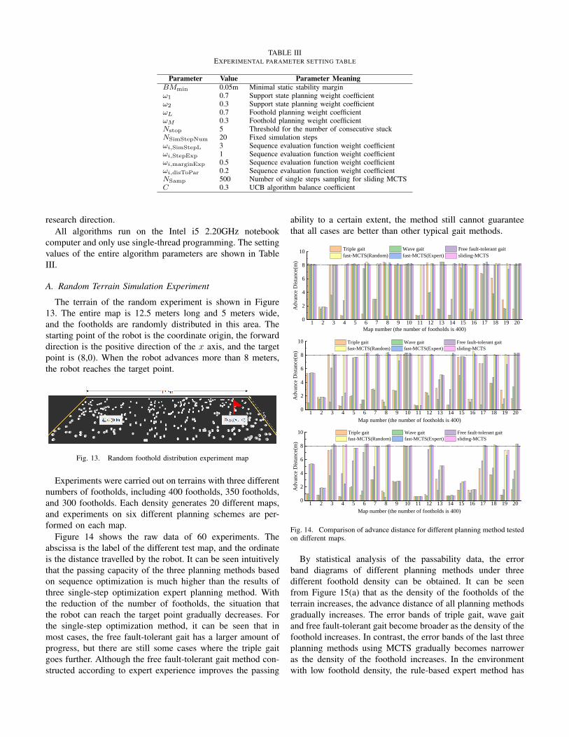
TABLE IIIEXPERIMENTAL PARAMETER SETTING TABLE
Parameter Value Parameter MeaningBMmin 0.05m Minimal static stability marginω1 0.7 Support state planning weight coefficientω2 0.3 Support state planning weight coefficientωL 0.7 Foothold planning weight coefficientωM 0.3 Foothold planning weight coefficientNstop 5 Threshold for the number of consecutive stuckNSimStepNum 20 Fixed simulation stepsωi,SimStepL 3 Sequence evaluation function weight coefficientωi,StepExp 1 Sequence evaluation function weight coefficientωi,marginExp 0.5 Sequence evaluation function weight coefficientωi,disToPar 0.2 Sequence evaluation function weight coefficientNSamp 500 Number of single steps sampling for sliding MCTSC 0.3 UCB algorithm balance coefficient
research direction.All algorithms run on the Intel i5 2.20GHz notebook
computer and only use single-thread programming. The settingvalues of the entire algorithm parameters are shown in TableIII.
A. Random Terrain Simulation Experiment
The terrain of the random experiment is shown in Figure13. The entire map is 12.5 meters long and 5 meters wide,and the footholds are randomly distributed in this area. Thestarting point of the robot is the coordinate origin, the forwarddirection is the positive direction of the x axis, and the targetpoint is (8,0). When the robot advances more than 8 meters,the robot reaches the target point.
Fig. 13. Random foothold distribution experiment map
Experiments were carried out on terrains with three differentnumbers of footholds, including 400 footholds, 350 footholds,and 300 footholds. Each density generates 20 different maps,and experiments on six different planning schemes are per-formed on each map.
Figure 14 shows the raw data of 60 experiments. Theabscissa is the label of the different test map, and the ordinateis the distance travelled by the robot. It can be seen intuitivelythat the passing capacity of the three planning methods basedon sequence optimization is much higher than the results ofthree single-step optimization expert planning method. Withthe reduction of the number of footholds, the situation thatthe robot can reach the target point gradually decreases. Forthe single-step optimization method, it can be seen that inmost cases, the free fault-tolerant gait has a larger amount ofprogress, but there are still some cases where the triple gaitgoes further. Although the free fault-tolerant gait method con-structed according to expert experience improves the passing
ability to a certain extent, the method still cannot guaranteethat all cases are better than other typical gait methods.
1 2 3 4 5 6 7 8 9 10 11 12 13 14 15 16 17 18 19 200
2
4
6
8
10
Ad
van
ce D
ista
nce
(m)
Map number (the number of footholds is 400)
Triple gait Wave gait Free fault-tolerant gait
fast-MCTS(Random) fast-MCTS(Expert) sliding-MCTS
1 2 3 4 5 6 7 8 9 10 11 12 13 14 15 16 17 18 19 200
2
4
6
8
10
Ad
van
ce D
ista
nce
(m)
Map number (the number of footholds is 400)
Triple gait Wave gait Free fault-tolerant gait
fast-MCTS(Random) fast-MCTS(Expert) sliding-MCTS
1 2 3 4 5 6 7 8 9 10 11 12 13 14 15 16 17 18 19 200
2
4
6
8
10
Ad
van
ce D
ista
nce
(m)
Map number (the number of footholds is 400)
Triple gait Wave gait Free fault-tolerant gait
fast-MCTS(Random) fast-MCTS(Expert) sliding-MCTS
Fig. 14. Comparison of advance distance for different planning method testedon different maps.
By statistical analysis of the passability data, the errorband diagrams of different planning methods under threedifferent foothold density can be obtained. It can be seenfrom Figure 15(a) that as the density of the footholds of theterrain increases, the advance distance of all planning methodsgradually increases. The error bands of triple gait, wave gaitand free fault-tolerant gait become broader as the density of thefoothold increases. In contrast, the error bands of the last threeplanning methods using MCTS gradually becomes narroweras the density of the foothold increases. In the environmentwith low foothold density, the rule-based expert method has

300 320 340 360 380 400
2
3
4
5
6
7
8
Triple gait
Wave gait
Free fault-tolerant gait
fast-MCTS(Random)
fast-MCTS(Expert)
sliding-MCTS
Advan
ce D
ista
nce
(m)
Foothold number
(b) (c)
300 320 340 360 380 4000.05
0.10
0.15
0.20
0.25
0.30
0.35
0.40A
ver
age
step
leng
th(m
/ste
p)
Foothold number
Triple gait
Wave gait
Free fault-tolerant gait
fast-MCTS(Random)
fast-MCTS(Expert)
sliding-MCTS
300 320 340 360 380 400
0
2
4
6
8
10 Triple Gait
Ad
van
ce d
ista
nce
(m)
Foothold number300 320 340 360 380 400
0
2
4
6
8
10 Wave gait
Ad
van
ce d
ista
nce
(m)
Foothold number300 320 340 360 380 400
0
2
4
6
8
10 Free fault-tolerant gait
Ad
van
ce d
ista
nce
(m)
Foothold number
300 320 340 360 380 400
0
2
4
6
8
10 fast-MCTS(Random)
Ad
van
ce d
ista
nce
(m)
Foothold number300 320 340 360 380 400
0
2
4
6
8
10 fast-MCTS(Expert)
Ad
van
ce d
ista
nce
(m)
Foothold number300 320 340 360 380 400
0
2
4
6
8
10 sliding-MCTS
Ad
van
ce d
ista
nce
(m)
Foothold number(a)
Fig. 15. Experimental data of different planning methods under different foothold density environments:(a)Forward distance error band diagram for differentplanning methods. (b)The comparison chart of the average advance distance represents the passing ability of the robot. (c)Comparison of the average stepsize of the robot. This can indicate the robot’s advancing speed.
poor passability. Therefore, in most cases, the robot has asmall travel distance. The increase in the density of footholdshas improved the robot’s passability. However, there are stillsome maps that the robot cannot pass due to the defeats ofthe rule-based method. Therefore, the result shows that theerror band becomes wider with the rise of the foothold densityof terrain. MCTS-based sequence optimization methods aredifferent. Most of the latter three planning methods can stilltravel long distances in low foothold density environment, anda small part cannot pass because the environment is too harsh.When the foothold density of terrain increases, the robot canreach the destinations almost for all maps. Therefore, the resultshows that the error band becomes narrower with the rise ofthe foothold density of terrain.
Compare the passing capabilities of all planning methods,as shown in Figure 15(b). It can be seen that the free fault-tolerant gait has significantly higher passing capacity than the
diagonal gait and wave gait. In terms of passing ability, thethree planning methods using sequence optimization are farsuperior to the first three methods. The passing capacity ofsliding-MCTS and fast-MCTS is the best.
In terms of forward speed, we use the average length of theentire planning sequence to represent the forward speed ofthe robot. According to Figure 15(c), the diagonal gait is thefastest, and Fast-MCTS (Expert) is the second-fastest one. Thefree fault-tolerant gait has a slower walking speed than Sliding-MCTS in a sparse foothold environment, and the walkingspeed is faster than free fault-tolerant gait when the footholddensity of terrain is denser. It can be seen that the Sliding-MCTS method can ensure the best passing ability, besides itcan search for a high-speed gait sequence in a sparse footholdenvironment. The slowest speeds are diagonal gait and Fast-MCTS (Random). Although Fast-MCTS (Random) has a highpassing capacity, the sequence it searches for has not been

Wave gait
Sliding-
MCTSFree fault-
tolerant gait
Fast-MCTS
(Expert)
Sliding-MCTS
(Random)
Passability
good
poor
Triple gait
Sliding-
MCTS
Wave gait
Free fault-
tolerant gait
Fast-MCTS
(Expert)
Sliding-MCTS
(Random)
Average step Length
big
small
Triple gaitWave gait
Sliding-
MCTSFree fault-
tolerant gait
Fast-MCTS
(Expert)
Sliding-MCTS
(Random)
Single step planning time
short
long
Triple gait
300 320 340 360 380 4002.142.162.182.202.222.242.262.282.302.32
Wave gait
Sin
gle
ste
p p
lan
nin
g t
ime(
ms)
Foothold number300 320 340 360 380 400
2.402.452.502.552.602.652.702.75 Triple gait
Sin
gle
ste
p p
lannin
g t
ime(
ms)
Foothold number300 320 340 360 380 400
2.42.52.62.72.82.93.03.13.2
Free fault-tolerante gait
Sin
gle
ste
p p
lan
nin
g t
ime(m
s)
Foothold number
300 320 340 360 380 400
-1k
0
1k
2k
3k fast-MCTS(Random)
Sin
gle
ste
p p
lan
nin
g t
ime(
ms)
Foothold number300 320 340 360 380 400
-0.2k0.0k0.2k0.4k0.6k0.8k1.0k1.2k
fast-MCTS(Expert)
Sin
gle
ste
p p
lann
ing t
ime(
ms)
Foothold number300 320 340 360 380 400
18k20k22k24k26k28k30k32k34k36k38k sliding-MCTS
Sin
gle
ste
p p
lan
nin
g t
ime(
ms)
Foothold number
(a)
(b)
Fig. 16. (a)Single-step planning time error band diagram for different planning methods. (b)Index comparison chart of different planning methods
optimized by a large number of samples, resulting in manyinvalid states in the entire sequence and the lowest speed.
To compare the planning time of the algorithms, we use thesingle-step planning time of the entire sequence to represent.As shown in Figure 16(a), the gait planning time of the firstthree expert methods is about 3ms, and the planning timeincreases as the density of the foothold increases. It is becausewhen the density of foothold becomes larger, there are moreavailable foothold can be selected, and more support statescan be chosen by free fault-tolerant gait. And it takes moretime to calculate with the increase of foothold density. Thesingle-step planning time of Fast-MCTS algorithm is about1s. As the environment becomes harsher, the search timegradually increases. For certain sparse foothold environments,the algorithm occasionally finds solution sequences quickly.So this leads to a larger error band for planning time inenvironments with low foothold density. The search timeof the Sliding-MCTS method is determined by the numberof expansion nodes Nsliding planned for each step and thefixed number of simulation steps NSimStepNum. Its single-step planning time is about 30s. The reason that the planningtime becomes longer as the foothold density increases is the
same as the free fault-tolerant gait. In a low-density footholdenvironment, the number of invalid nodes is unstable. Thehigher the density of environmental footholds, the less thenumber of invalid node expansions. This is also the reasonwhy the error band gradually narrows.
In summary, as shown in Figure 16(b), the six planningmethods have their advantages and disadvantages. In terms ofpassability, Fast-MCTS (Random) and Sliding-MCTS methodshave the highest passability. Expert planning methods havevery poor passability, and free fault-tolerant gaits that takeinto account environmental fault tolerance have slightly betterpassability. In terms of walking speed, the triple gait is thefastest, followed by Fast-MCTS (Expert), and the speeds offree fault-tolerant gait and Sliding-MCTS are both fast. Theother two methods are slow. In terms of planning time, thethree planning methods using MCTS take longer, and the Fast-MCTS single-step planning time is about one second. Thesingle-step planning time of Sliding-MCTS is relatively long,and it is related to its set parameters. However, the planningof each step of this method is independent and is not affectedby subsequent plan. Therefore, Sliding-MCTS is suitable forlocal planning.

Fig. 17. (a) Artificially designed terrains. (b)(c)(d) Screenshots and gait charts of the robot’s passage through three different terrains. The light blue partof the gait diagram corresponds to the screenshot of the robot walking. Each screenshot of the robot represents an operating state, and the red curve is thetrajectory of the swinging leg at this time. In the gait diagram, black indicates that the leg is a swinging leg, yellow indicates that the leg is a supporting leg,and red indicates that the leg is a fault-tolerant leg.
B. Special Terrain Simulation Experiment
The proposed sliding-MCTS algorithm is applied to someartificial terrain to verify its validity. As shown in Figure 17(a),we design 3 different terrains. The first type represents thesegmented terrain that can be seen in real life. The secondterrain is more extreme, with a rectangular area deductedin the middle of the flat terrain. The third type of terrainrepresents continuous trench terrain, and the width of thetrench is inconsistent. All three types of terrain robots canpass smoothly. Figure 17 is a screenshot of a part of therobot passing the terrain and a gait diagram of the entireprocess. Figures 17 (b)(c) show that in a harsh environment,the robot can temporarily lift its legs without an effectivefoothold through such terrain. In Figure 17 (c), the robot evenbecomes a quadruped robot to cross the terrain. In Figure17 (d), the robot continuously adjusts the step size to crossthe continuous trench terrain effectively. In the gait diagram,black represents the swing state, yellow represents the support
state, and red represents the wrong leg (still belongs to swingstate). It can be seen that the robot can successfully pass thesechallenging terrains by continuously adjusting the gait.
C. Physical robot experiment
We carried out some physical experiments to illustrate thefeasibility of the algorithm. The experiment terrain is set inadvance, as shown in Figure 18, bricks represent discrete areaswhere the robot’s feet can land. The position of the robot ismeasured by a visual capture system. The planning methoduses the Sliding-MCTS algorithm proposed in this paper. Therobot needs to go straight from one side of the field to theend of the field. It can be seen that the robot can choose thebricks scattered on the ground as a foothold, and successfullyreached the target position. The experimental results show thatthe algorithm proposed in this paper can be effectively appliedto physical robots.

Fig. 18. Elspider walking on discrete bricks.
V. CONCLUSION
In this work, a gait foothold planning method based onMCTS is proposed. Before introducing the sequence optimiza-tion method, according to the harshness of the environment,we combine fault-tolerant gait planning and free gait, a freefault-tolerant gait method based on the expert planning methodis proposed. According to the particularity of the applicationof MCTS in the field of legged robots, we have made somechanges to the standard MCST and introduced two methods,Fast MCTS and Sliding MCTS. FastMCTS can quickly im-prove the passing ability of the default planning method, but itis not very convergent. SlidingMCTS can effectively balancethe search time and convergence while having a good passingability. The simulation experiments verify the advantagesand disadvantages of different methods, the rule-based expertmethod has a fast calculation speed, while the optimization-based method has better passability. The calculation time ofthe optimization method can also meet real-time requirements.Finally, through artificially designing some challenging terrainto test the algorithm, and applying the algorithm on thephysical robot, the results show that the proposed method canhave a good passability in the sparse foothold environment. Inthe future, we will also continue to study how to increase thesearch speed of the algorithm and combine it with machinevision to explore the wild environment in real-time.
VI. ACKNOWLEDGEMENTS
This study was supported in part by the NationalNatural Science Foundation of China(91948202), andthe National Key Research and Development Project ofChina(2019YFB1309500).
REFERENCES
[1] EZ Moore, D Campbell, Felix Grimminger, and Mar-tin Buehler. Reliable stair climbing in the simplehexapod’rhex’. In Proceedings 2002 IEEE Interna-tional Conference on Robotics and Automation (Cat. No.02CH37292), volume 3, pages 2222–2227. IEEE, 2002.
[2] Lutfi Taner Tunc and Jay Shaw. Experimental study oninvestigation of dynamics of hexapod robot for mobilemachining. The International Journal of Advanced Man-ufacturing Technology, 84(5-8):817–830, 2016.
[3] G Picardi, M Chellapurath, S Iacoponi, S Stefanni,C Laschi, and M Calisti. Bioinspired underwater leggedrobot for seabed exploration with low environmentaldisturbance. Science Robotics, 5(42), 2020.
[4] Mrinal Kalakrishnan, Jonas Buchli, Peter Pastor, MichaelMistry, and Stefan Schaal. Learning, planning, andcontrol for quadruped locomotion over challenging ter-rain. The International Journal of Robotics Research,30(2):236–258, 2011.
[5] Dominik Belter, Przemysław Łabecki, and PiotrSkrzypczynski. Adaptive motion planning forautonomous rough terrain traversal with a walkingrobot. Journal of Field Robotics, 33(3):337–370, 2016.
[6] Péter Fankhauser, Marko Bjelonic, C Dario Bellicoso,Takahiro Miki, and Marco Hutter. Robust rough-terrainlocomotion with a quadrupedal robot. In 2018 IEEEInternational Conference on Robotics and Automation(ICRA), pages 1–8. IEEE, 2018.
[7] SK-K Chu and GK-H Pang. Comparison between differ-ent model of hexapod robot in fault-tolerant gait. IEEETransactions on Systems, Man, and Cybernetics-Part A:Systems and Humans, 32(6):752–756, 2002.

[8] Joaquin Estremera, Jose A Cobano, and P GonzalezDe Santos. Continuous free-crab gaits for hexapod robotson a natural terrain with forbidden zones: An applicationto humanitarian demining. Robotics and AutonomousSystems, 58(5):700–711, 2010.
[9] Marko Bjelonic, Navinda Kottege, Timon Homberger,Paulo Borges, Philipp Beckerle, and Margarita Chli.Weaver: Hexapod robot for autonomous navigationon unstructured terrain. Journal of Field Robotics,35(7):1063–1079, 2018.
[10] Dominik Belter, Jan Wietrzykowski, and PiotrSkrzypczynski. Employing natural terrain semantics inmotion planning for a multi-legged robot. Journal ofIntelligent & Robotic Systems, 93(3-4):723–743, 2019.
[11] EI Kugushev. Problems of selecting a gait for an inte-grated locomotion robot. In in Proceedings of the FourthInternational Joint Conference on Artificial Intelligence.Citeseer, 1975.
[12] Robert B McGhee and Geoffrey I Iswandhi. Adaptivelocomotion of a multilegged robot over rough terrain.IEEE transactions on systems, man, and cybernetics,9(4):176–182, 1979.
[13] Shigeo Hirose. A study of design and control of aquadruped walking vehicle. The International Journalof Robotics Research, 3(2):113–133, 1984.
[14] Joaquin Estremera and Pablo Gonzalez de Santos. Gen-erating continuous free crab gaits for quadruped robotson irregular terrain. IEEE Transactions on Robotics,21(6):1067–1076, 2005.
[15] M Lo Shik. Control of walking and running by meansof electrical stimulation of the midbrain. Biophysics,11:659–666, 1966.
[16] ST Venkataraman. A simple legged locomotion gaitmodel. Robotics and Autonomous Systems, 22(1):75–85,1997.
[17] Paolo Arena, Luigi Fortuna, Mattia Frasca, and GiovanniSicurella. An adaptive, self-organizing dynamical systemfor hierarchical control of bio-inspired locomotion. IEEETransactions on Systems, Man, and Cybernetics, Part B(Cybernetics), 34(4):1823–1837, 2004.
[18] Chengju Liu, Danwei Wang, and Qijun Chen. Centralpattern generator inspired control for adaptive walkingof biped robots. IEEE Transactions on Systems, Man,and Cybernetics: Systems, 43(5):1206–1215, 2013.
[19] Cristina P Santos and Vítor Matos. Gait transitionand modulation in a quadruped robot: A brainstem-like modulation approach. Robotics and AutonomousSystems, 59(9):620–634, 2011.
[20] Mustafa Suphi Erden and Kemal Leblebicioglu. Free gaitgeneration with reinforcement learning for a six-leggedrobot. Robotics and Autonomous Systems, 56(3):199–212, 2008.
[21] Eric Krotkov and Reid Simmons. Perception, planning,and control for autonomous walking with the amblerplanetary rover. The International journal of roboticsresearch, 15(2):155–180, 1996.
[22] John R Rebula, Peter D Neuhaus, Brian V Bonnlander,Matthew J Johnson, and Jerry E Pratt. A controllerfor the littledog quadruped walking on rough terrain.In Proceedings 2007 IEEE International Conference onRobotics and Automation, pages 1467–1473. IEEE, 2007.
[23] J Zico Kolter, Pieter Abbeel, and Andrew Y Ng. Hi-erarchical apprenticeship learning with application toquadruped locomotion. In Advances in Neural Informa-tion Processing Systems, pages 769–776, 2008.
[24] Mrinal Kalakrishnan, Jonas Buchli, Peter Pastor, andStefan Schaal. Learning locomotion over rough terrainusing terrain templates. In 2009 IEEE/RSJ InternationalConference on Intelligent Robots and Systems, pages167–172. IEEE, 2009.
[25] Dominik Belter and Piotr Skrzypczynski. Rough terrainmapping and classification for foothold selection in awalking robot. Journal of Field Robotics, 28(4):497–528,2011.
[26] David Silver, Aja Huang, Chris J Maddison, ArthurGuez, Laurent Sifre, George Van Den Driessche, JulianSchrittwieser, Ioannis Antonoglou, Veda Panneershel-vam, Marc Lanctot, et al. Mastering the game of gowith deep neural networks and tree search. nature,529(7587):484, 2016.
[27] David Silver, Julian Schrittwieser, Karen Simonyan,Ioannis Antonoglou, Aja Huang, Arthur Guez, ThomasHubert, Lucas Baker, Matthew Lai, Adrian Bolton, et al.Mastering the game of go without human knowledge.nature, 550(7676):354–359, 2017.
[28] Cameron B Browne, Edward Powley, Daniel White-house, Simon M Lucas, Peter I Cowling, Philipp Rohlf-shagen, Stephen Tavener, Diego Perez, Spyridon Samoth-rakis, and Simon Colton. A survey of monte carlo treesearch methods. IEEE Transactions on ComputationalIntelligence and AI in games, 4(1):1–43, 2012.
[29] David Lenz, Tobias Kessler, and Alois Knoll. Tacticalcooperative planning for autonomous highway drivingusing monte-carlo tree search. In 2016 IEEE IntelligentVehicles Symposium (IV), pages 447–453. IEEE, 2016.
[30] Mohammad Naghshvar, Ahmed K Sadek, and Auke JWiggers. Risk-averse behavior planning for au-tonomous driving under uncertainty. arXiv preprintarXiv:1812.01254, 2018.
[31] Patrick Clary, Pedro Morais, Alan Fern, and JonathanHurst. Monte-carlo planning for agile legged locomotion.In Twenty-Eighth International Conference on AutomatedPlanning and Scheduling, 2018.
[32] Bernardo Aceituno-Cabezas, Carlos Mastalli, HongkaiDai, Michele Focchi, Andreea Radulescu, Darwin GCaldwell, José Cappelletto, Juan C Grieco, GerardoFernández-López, and Claudio Semini. Simultaneouscontact, gait, and motion planning for robust multileggedlocomotion via mixed-integer convex optimization. IEEERobotics and Automation Letters, 3(3):2531–2538, 2017.
[33] Kourosh Naderi, Joose Rajamäki, and Perttu Hämäläinen.Discovering and synthesizing humanoid climbing move-

ments. ACM Transactions on Graphics (TOG), 36(4):43,2017.
[34] Vassilios Tsounis, Mitja Alge, Joonho Lee, FarbodFarshidian, and Marco Hutter. Deepgait: Planning andcontrol of quadrupedal gaits using deep reinforcementlearning. arXiv preprint arXiv:1909.08399, 2019.
[35] Levente Kocsis and Csaba Szepesvári. Bandit basedmonte-carlo planning. In European conference on ma-chine learning, pages 282–293. Springer, 2006.
[36] Jonathan S Matthis and Brett R Fajen. Visual controlof foot placement when walking over complex terrain.Journal of experimental psychology: human perceptionand performance, 40(1):106, 2014.
[37] Zhen Liu, Hong-Chao Zhuang, Hai-Bo Gao, Zong-QuanDeng, and Liang Ding. Static force analysis of footof electrically driven heavy-duty six-legged robot undertripod gait. Chinese Journal of Mechanical Engineering,31(1):63, 2018.
[38] Yufei Liu, Haibo Gao, Liang Ding, Guangjun Liu,Zongquan Deng, and Nan Li. State estimation of a heavy-duty hexapod robot with passive compliant ankles basedon the leg kinematics and imu data fusion. Journal ofMechanical Science and Technology, 32(8):3885–3897,2018.
[39] Haibo Gao, Yufei Liu, Liang Ding, Guangjun Liu,Zongquan Deng, Yiqun Liu, and Haitao Yu. Lowimpact force and energy consumption motion planningfor hexapod robot with passive compliant ankles. Journalof Intelligent & Robotic Systems, 94(2):349–370, 2019.

Algorithm 1 Fast Monte Carlo tree search algorithmInput: Initial robot state Φ0, target position Pdestination
Output: Solution sequence Ψ = {Φ1,Φ2...Φk}1: function FASTMCTSSEARCH(Φ0, Pdestination)2: Create the root node NΦ0
3: Set the expansion node NΦexpand= NΦ0
4: Set the furthest node of the master branch NΦend
5: create variable disMax = 06: while "Node NΦend
has not reached the destination or extended node NΦexpandis not the root node." do
7: Ssequence, dis = EXPANDANDSIMULATION(NΦexpand)
8: if dis > disMax then9: NΦend
= UPDATAMASTERBRANCH(NΦexpand,Ssequence)
10: disMax = dis11: end if12: NΦexpand
= TRACEBACK(NΦend)
13: end while14: return State sequence Ψ = {Φ1,Φ2...Φk} between NΦ0
and NΦend.
15: end function16:17: function EXPANDANDSIMULATION(NΦ)18: Create a sequence storage variable sequenceList19: Create a distance storage variable disList20: for each NΦi
in the alternative nodes of Φ do21: Add child node NΦi
to NΦ
22: dis, Ssequence = SIMULATION(NΦi )23: disList.add(dis)24: sequenceList.add(Ssequence)25: end for26: index = arg max
i(disList)
27: return sequenceList[index], dis[index]28: end function29:30: function SIMULATION(NΦ)31: NΦtmp
= NΦ
32: Create a node sequence storage variable Ssequence
33: while Node NΦendhas not reached the destination or Ccount > NSimStepNum do
34: Generate the next state Φnext of Φtmp by expert algorithm or random algorithm.35: if Distance between Φtmp and Φnext < 0.01m then36: Ccount = Ccount + 137: end if38: NΦtmp = NΦnext
39: Ssequence.add(NΦtmp)
40: end while41: return the forward distance of NΦtmp
, Ssequence
42: end function43:44: function UPDATAMASTERBRANCH(NΦ, Ssequence)45: for each NΦi
in Ssequence do46: Add child node NΦi
to NΦ
47: NΦ = NΦi
48: end for49: return NΦ
50: end function

51: function TRACEBACK(NΦ)52: while The number of alternate states of NΦ is not 0, and NΦ is not expanded do53: NΦ = the parent node of NΦ
54: end while55: return NΦ
56: end function
Algorithm 2 Sliding Monte Carlo tree search algorithmInput: Initial robot state Φ0, target position Pdestination
Output: Solution sequence Ψ = {Φ1,Φ2...Φk}1: function SLIDINGMCTSSEARCH(Φ0, Pdestination)2: Create the root node NΦ0
3: NΦexpand= NΦ0
4: Create a furthest simulation distance variable Lmax
5: Create a sliding root node sequence storage variable Ssequence
6: while "Node NΦexpandhas not reached the destination or (the foward distance of NΦexpand
− Lmax) < threshold" do7: Create variable Count = 08: while Count < NSamp do9: Count = Count + 1
10: Φexpanded = TREEPOLICY(NΦ0)
11: J(.), Ltmp = SIMULATION(NΦexpand)
12: if Lmax < Ltmp then13: Lmax = Ltmp
14: end if15: BACKUPDATE(NΦexpand
, J(.))16: end while17: NΦbest
= GETBESTCHILD(NΦexpand, J(.))
18: Ssequence.add(NΦ0 )19: NΦ0 = NΦbest
20: end while21: return State sequence Ψ = {Φ1,Φ2...Φk} in Ssequence
22: end function23:24: function TREEPOLICY(NΦ)25: while 1 do26: if Node NΦ still has unexpanded alternative states then27: return EXPAND(NΦ)28: else29: NΦ = GETBESTCHILD(NΦ, C)30: end if31: end while32: end function33:34: function SIMULATION(NΦ)35: NΦtmp
= NΦ
36: Ccount = 037: while Ccount < NSimStepNum do38: Generate the next state Φnext of Φtmp by expert algorithm or random algorithm.39: Ccount = Ccount + 140: NΦtmp
= NΦnext
41: end while42: Calculate the evaluate value of node NΦ: JSimStepL,JStepExp,JmarginExp,JdisToPar
43: return the forward distance of NΦtmp, J(.)
44: end function
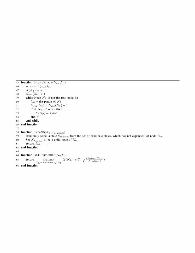
45: function BACKUPDATE(NΦ, J(.))46: score =
∑ω(.)J(.)
47: X(NΦ) = score48: Nvist(NΦ) = 149: while Node NΦ is not the root node do50: NΦ = the parant of NΦ
51: Nvist(NΦ) = Nvist(NΦ) + 152: if X(NΦ) < score then53: X(NΦ) = score54: end if55: end while56: end function57:58: function EXPAND(NΦ, Ssequence)59: Randomly select a state Φrandom from the set of candidate states, which has not expanded, of node NΦ.60: Set NΦrandom
to be a child node of NΦ
61: return NΦrandom
62: end function63:64: function GETBESTCHILD(NΦ,C)65: return arg max
NΦi∈ children of NΦ
(X(NΦi) + C ·√
2·lnNvist(NNΦ)
Nvist(NΦi) )
66: end function