article stability and gait planning of 3-upu hexapod
TRANSCRIPT

Article
Stability and Gait Planning of 3-UPU Hexapod
Walking Robot
Ruiqin Li 1*, Hongwei Meng 1, Shaoping Bai 2, Yinyin Yao 1, Jianwei Zhang 1,3
1 School of Mechanical Engineering, North University of China, Taiyuan 030051, China;
2 Department of Mechanical and Manufacturing Engineering, Aalborg University, Aalborg, Denmark
3 Department of Informatics, University of Hamburg, Hamburg, Germany
* Correspondence: [email protected]; Tel.: +86-351-3921300
Abstract: The paper presents an innovative hexapod walking robot built with 3-UPU parallel
mechanism. In the robot, the parallel mechanism is used as both an actuator to generate walking
and also a connecting body to connect two groups of three legs, thus enables the robot to walk with
simple gait by very few motors. In the paper, the forward and inverse kinematics solutions are
obtained. The workspace of the parallel mechanism is analyzed using limit boundary search
method. The walking stability of the robot is analyzed, which yields the robot’s maximum step
length. The gait planning of the hexapod walking robot is studied for walking on both flat and
uneven terrains. The new robot, combining the advantages of parallel robot and walking robot, has
a large carrying capacity, strong passing ability, flexible turning ability, and simple gait control for
its deployment for uneven terrain.
Keywords: hexapod walking robot; 3-UPU parallel mechanism; kinematics; stability; gait planning
1. Introduction
Legged robot is advantageous over the wheeled robot in their flexibility of movement and the
adaptability of the environment. Legged robot can adapt to different terrains. A multi-DOF design
enables it to actively adjust the height of the body according to the operational requirements to ensure
the balance and stability of the body.
Many legged robots have been developed up to date [1-4]. NOROS robot developed by Ding et
al. [2-3] is a modular walking robot. It consists of up to eight autonomous leg modules, each equipped
with various sensors. A self-recovery approach is applied by imitating the self-recovery motion of
insects. Ma et al. [4] proposed a robot, which consists of six legs of the same structure distributed
evenly on a platform. Each leg of the robot has a structure similar to that of a telescopic parallelogram
mechanism with folding capability, which is beneficial to the gait planning and real-time control of
the robot. The parallel type mobile robot formed by parallel mechanism applied to the legged robot
can greatly improve the load/weight ratio of the mobile robot, reduce the energy consumption and
prolong the walking time. Our interest is to develop a hexapod walking robot that utilizes a parallel
mechanism, namely, a three-DOF translational 3-UPU parallel mechanism.
The concept of 3-UPU parallel mechanism was first introduced by Tsai [5], which can produce
three-dimensional translation movement. Gregorio [6] presented a 3-UPU parallel manipulator,
named 3-UPU wrist for spherical motions with its prismatic pairs actuated. Ji et al. [7] proposed a 3-
UPU translational parallel robotic manipulator with an equal offset in its six universal joints and
obtained 16 solutions of the forward kinematics. Han et al. [8] analyzed kinematic sensitivity of the
3-UPU parallel mechanism. Huang et al. [9] studied feasible instantaneous motions and kinematic
characteristics of an orthogonal 3-UPU parallel mechanism. Wu et al. [10] designed a configuration-
switch mechanism for 3-UPU parallel mechanism.
The kinematics and dynamics analyses of 3-UPU parallel mechanisms have been well developed
in literatures [11-15]. Two novel 3-UPU parallel kinematics machines with two rotations and one
Preprints (www.preprints.org) | NOT PEER-REVIEWED | Posted: 23 August 2018 doi:10.20944/preprints201808.0416.v1
© 2018 by the author(s). Distributed under a Creative Commons CC BY license.

2 of 17
translation are proposed in literature [13]. In addition, singularity [14-15] and stiffness [16] of the 3-
UPU parallel mechanism are also studied.
There are some reports about applications of parallel mechanism in mobile robots. A rolling biped
robot was proposed based on a 3-UPU parallel mechanism [17]. Gait and stability analyses were
presented and four rolling modes of the mechanism were discussed and simulated. Gu [18] proposed
to apply a typical 3-UPU parallel mechanism in a quadruped walking robot. Wang et al. [19]
presented a biped locomotor consisted of two identical 3-DOF tripod leg mechanisms with a parallel
manipulator architecture. Sugahara et al. [20] presented a design of a battery driven bipedal robot,
which used 6-DOF parallel mechanism for its each leg. Wang et al. [21] proposed a quadruped/biped
reconfigurable parallel legged walking robot, in which the robot can change between biped and
quadruped walking modes according to real-time road conditions. Each leg is composed of a 3-UPU
parallel mechanism. The robot walks as a quadruped generally and changes to bipedal walking when
walking up and down stairs.
Walking robots have to walk following a certain pattern of leg movement, namely, the gaits.
Hirakoso et al. [22] developed a multi-legged gait prototype robot with four legs consisted of
redundant joint. An optimal control system was proposed to control any motion for the four-legged
robot with redundant joint. Sun et al. [23] proposed a transformable wheel-legged mobile robot that
integrated stability and maneuverability of wheeled robot and obstacle climbing capability of legged
robot. When under wheeled mode, the robot avoids the obstacle using a motion control strategy that
combines of three basic cases of translation, rotation and arc motion, while the robot climbs the
obstacle by legs. A method of free gait generation that utilizes the primary/secondary gait for both
straight line and circular body trajectories was proposed by Bai [24]. Four constraints of primary gait
were discussed. When the walking machine cannot move using the primary gait, the secondary gait
is generated to adjust the leg position and enable the vehicle to keep on moving. Gait planning
combined with path planning was also developed [25-26].
Gong et al. [27] focused on the dynamic gaits control for complex robot with twenty DOFs. Using
composite cycloid to plan the swing foot trajectory curve made the velocity and acceleration to be
zero which can reduce the impact of collision with ground and energy loss. Li et al. [28] presented a
three-dimensional model of a quadruped robot which has six DOFs on torso and five DOFs on each
leg. Matsuzawa et al. [29] proposed a crawling motion to reduce the risk of malfunction due to falling
when a legged robot travels across rough terrain.
Winkler et al. [30-31] developed trajectory planning for legged locomotion that automatically
determines the gait sequence, step timings, footholds, swing-leg motions, and six-dimensional body
motion over rough terrain, without any additional modules. Neunert et al. [32] proposed a trajectory
optimization framework for whole-body motion planning through contacts. Zhao et al. [33]
developed a motion generation approach for a hexapod robot Octopus-III to control the robot to walk
along the planned trajectory. The approach coordinates the body motion and the feet motions to fulfill
requirements of walking stability and kinematic feasibility simultaneously. Oliveira et al. [34] studied
locomotion patterns of hexapod robots, including metachronal wave gait, tetrapod and tripod gaits.
Up to date, the reported research works of legged robots are mainly focused on biped, quadruped
and hexapod robots. Most of these robots have independent driving joints on the legs, which requires
many actuators. In the case of a single leg of three joints, a hexapod robot needs at least 18 motors
which greatly increases the weight of the robot. Moreover, the position of each foot has to be
considered, which adds complexity to control.
The paper presents a hexapod walking robot designed with a 3-UPU parallel mechanism, aiming
to reduce the number of driving motors and improve load capacity and terrain adaptability. The new
design is characterized by alternating motion between the two platforms of the 3-UPU parallel
mechanism to realize robot walking. The parallel mechanism is used as both an actuator to generate
walking and also a connecting body to connect two groups of three legs. The new walking robot is
thus able to walk with simple gait by very few motors.
The paper is organized as follows. Firstly, the configuration of the hexapod walking robot is
presented in Section 2. The forward and inverse kinematic solutions of the 3-UPU parallel mechanism
Preprints (www.preprints.org) | NOT PEER-REVIEWED | Posted: 23 August 2018 doi:10.20944/preprints201808.0416.v1
3 of 17
are derived in Section 3. The workspace of the robot is obtained using joint constraint conditions and
inverse kinematics equation in Section 4. The movement stability of the robot is analyzed using the
center of gravity projection method in Section 5. The gait of the robot is planned under the condition
of ensuring the efficiency of the walking mode of the robot in Section 6. A case study is included in
Section 7, and the work is concluded in Section 8.
2. Configuration of 3-UPU Hexapod Walking Robot
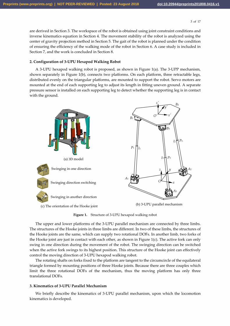
A 3-UPU hexapod walking robot is proposed, as shown in Figure 1(a). The 3-UPP mechanism,
shown separately in Figure 1(b), connects two platforms. On each platform, three retractable legs,
distributed evenly on the triangular platforms, are mounted to support the robot. Servo motors are
mounted at the end of each supporting leg to adjust its length in fitting uneven ground. A separate
pressure sensor is installed on each supporting leg to detect whether the supporting leg is in contact
with the ground.
Figure 1. Structure of 3-UPU hexapod walking robot
The upper and lower platforms of the 3-UPU parallel mechanism are connected by three limbs.
The structures of the Hooke joints in three limbs are different. In two of these limbs, the structures of
the Hooke joints are the same, which can supply two rotational DOFs. In another limb, two forks of
the Hooke joint are just in contact with each other, as shown in Figure 1(c). The active fork can only
swing in one direction during the movement of the robot. The swinging direction can be switched
when the active fork swings to its highest position. This structure of the Hooke joint can effectively
control the moving direction of 3-UPU hexapod walking robot.
The rotating shafts on forks fixed to the platform are tangent to the circumcircle of the equilateral
triangle formed by mounting positions of three Hooke joints. Because there are three couples which
limit the three rotational DOFs of the mechanism, thus the moving platform has only three
translational DOFs.
3. Kinematics of 3-UPU Parallel Mechanism
We briefly describe the kinematics of 3-UPU parallel mechanism, upon which the locomotion
kinematics is developed.
Swinging in one direction
Swinging in another direction
Swinging direction switching
(c) The orientation of the Hooke joint
(a) 3D model
z y
x
z' y'
x' O'
O
l1
l2
l3
P1
A1
P2
B3
P3
A2
A3
B1
B2
A3
(b) 3-UPU parallel mechanism
Preprints (www.preprints.org) | NOT PEER-REVIEWED | Posted: 23 August 2018 doi:10.20944/preprints201808.0416.v1

4 of 17
3.1. The Inverse Kinematics Solution
The moving, or the upper platform of 3-UPU parallel mechanism is a mechanism with only three-
dimensional translations. The inverse kinematics problem of 3-UPU parallel mechanism is to solve
the lengths (l1, l2, l3) of the equivalent driving links for given position (x, y, z) of the moving platform.
As shown in Figure 1(b), the moving coordinate system O′-x′y′z′ is connected to the moving
platform. The origin O′ is located at the center of the moving platform. x′ axis is coincident with O′B1,
and point B1 is located at the negative direction of x′ axis. y′ axis is parallel to line B3B2. z′ axis is
perpendicular to the upper platform and pointing away from the mechanism. The coordinate system
O-xyz is connected to the lower, or the static platform. The origin O is located at the center of the
static platform. x axis is coincided with OA1, and point A1 is located at the axis’ negative part. y axis is
parallel to line A3A2. z axis is perpendicular to the static platform and the direction is upward.
Moreover, the circumradii of the moving platform and the static platform are noted as r and R,
respectively. The equivalent link length of the limb i are noted by li (i=1, 2, 3).
According to the geometric characteristics of the mechanism, the closed vector loop equation is
established as
= + +-i i i iAB OA OO OB , (i=1, 2, 3) (1)
il=
i iA B , (i=1, 2, 3) (2)
Let the coordinate of the geometric center O in the static coordinate system O-xyz be (x, y, z).
The vector OO can be expressed as
= T
, ,x y zOO (3)
and iOA and
iO B (i=1, 2, 3) can be expressed as
=
=
=
T
T
2
T
3
- , 0, 0
1 3, , 0
2 2
1 3, - , 0
2 2
R
R R
R R
1OA
OA
OA
,
=
=
=
T
T
T
- , 0, 0
1 3, , 0
2 2
1 3, - , 0
2 2
r
r r
r r
1
2
3
O'B
O'B
O'B
(4)
From Equations (1), (3) and (4), the following expressions can be obtained.
= +
=
= +
T
T
2 2
T
3 3
, ,
1 3- , - ,
2 2
1 3- , ,
2 2
x y z
x y z
x y z
1 1A B
A B
A B
(5)
where = -R r .
According to Equation (2), the position inverse solution can be obtained.
( ) + + + = − + − + =
− + + + =
2 2 2 2
1
22
2 2
2
22
2 2
3
1 3
2 2
1 3
2 2
x y z l
x y z l
x y z l
(6)
When the basic geometric dimensions of the 3-UPU parallel mechanism and the position (x, y, z)
of the moving platform are known, the variation of the equivalent link length li (i=1, 2, 3) of three
limbs, i.e. the displacement of three prismatic pairs can be obtained using Equation (6). Similarly,
when the upper platform is a static platform and the lower platform is a moving platform, the static
Preprints (www.preprints.org) | NOT PEER-REVIEWED | Posted: 23 August 2018 doi:10.20944/preprints201808.0416.v1

5 of 17
coordinate system O-xyz is connected to the upper platform, while the moving coordinate system O′-
x′y′z′ is connected to the lower platform. The coordinate directions do not change, and the closed
vector loop equation is established as follows:
- + +=i i i iB A OB OO OA , (i=1, 2, 3) (7)
Similarly, the inverse position solution of the upper platform can be obtained as follows:
( ) − + + = + + + + =
+ + − + =
2 2 2 2
1
22
2 2
2
22
2 2
3
1 3
2 2
1 3
2 2
x y z l
x y z l
x y z l
(8)
3.2. The Kinematics Forward Solution
Giving the lengths (l1, l2, l3) of the prismatic pairs of three limbs, we need to solve the spatial
position (x, y, z) of the moving platform. The solutions of position (x, y, z) can be obtained numerically
using Equation (6).
4. Workspace of the 3-UPU Parallel Mechanism
4.1. Factors Influencing the Workspace of the 3-UPU Parallel Mechanism
The reachable workspace of the 3-UPU parallel mechanism is under the influence of several
factors: the shortest and longest distance of the limb and the range of rotation angle of Hooke joint.
(1) The shortest and longest distances of the limbs
The position (x, y, z) of the reference point of the moving platform is constrained by the equivalent
link length li (i=1, 2, 3) of the three limbs. The three prismatic pairs in the limbs act as driving inputs,
which makes the moving platform move in the workspace range. When the limb is the shortest or the
longest, the servo motor I, which acts as the prismatic pair, is in the zero position or the limit position.
The reference point of the moving platform reaches the boundary of the workspace.
Taking the upper platform as the moving platform, the equivalent link length li (i=1, 2, 3) of each
limb satisfy the following constraint:
min maxi
l l l (9)
where lmin and lmax are the minimum and maximum link lengths of the limb.
(2) The rotation angle range of the Hooke joint
The Hooke joints are used to connect the limbs to the upper and lower platforms. As shown in
Figure 2, the rotation angle θ1 of the Hooke joint connected to the limb is related to the length l1 of
the limb and the y coordinate of the moving platform. The rotation angle θ1 should satisfy:
= =11
1 1
arcsin arcsinyB E
l l (10)
The rotation angle θ2 of the Hooke joint connected to the static platform is related to the projection
length of the limb l1 at O-xz plane and the z coordinate of the moving platform. The rotation angle θ2
should satisfy:
= =2
2 21 1
arccos arccos-
EF z
A E l y (11)
Preprints (www.preprints.org) | NOT PEER-REVIEWED | Posted: 23 August 2018 doi:10.20944/preprints201808.0416.v1

6 of 17
(a) Angle θ1 of the Hooke joint (b) Angle θ2 of the Hooke joint (c) Rotation angles of the Hooke joint
Figure 2. Rotation angles of the Hooke joint in the 3-UPU parallel mechanism
4.2. Method for Determining Workspace of the 3-UPU Parallel Mechanism
The workspace of the 3-UPU parallel mechanism is determined using the limit boundary search
method. The idea is that when the position of the moving platform is known, the equivalent link
length li (i=1, 2, 3) of each limb can be calculated by the inverse solution equation of the mechanism
position. The rotation angles of Hooke joint can be solved using Equations (10) and (11). Then, these
results are compared with the corresponding limit values, respectively. If any of these values exceed
the allowable range, that is, the reference point is outside the workspace. The solutions are as follows:
(1) Defining the structure parameter of the mechanism, including: the circumradii r and R of the
upper and lower platforms, the maximum travel range of the equivalent link length li (i=1, 2, 3) of
limb i, the maximum rotation angle of Hooke joint.
(2) Defining the range of the coordinates (x, y, z) of the reference points of the moving platform,
or, the search space.
(3) The reference point coordinate is substituted into the position inverse solution equation of the
mechanism, the equivalent link length li (i=1, 2, 3) and the Hooke joint angles θ1, θ2 in the limbs are
obtained. The results are checked whether they are within the allowable range. If they are, these
points are recorded.
(4) The set of points satisfying the condition is the workspace of the 3-UPU parallel mechanism
when a given range of values has been searched.
The design parameters are given in Table 1. According to workspace search flow chart in Figure
3, the workspaces of the 3-UPU parallel mechanism are obtained using Matlab.
Table 1. Design parameters of the 3-UPU parallel mechanism
Parameter Symbol and unit
Equivalent circumradius of the upper platform r/mm
Equivalent circumradius of the lower platform R/mm
Range of the equivalent link length of limb i il i =( 1,2,3) /mm
Range of the rotation angle of the Hooke joint =( 1,2)iθ i /rad
θ1 θ2
A1
O
z y
x
B1
l1
E
F
θ1
θ2
Preprints (www.preprints.org) | NOT PEER-REVIEWED | Posted: 23 August 2018 doi:10.20944/preprints201808.0416.v1

7 of 17
z=z+Δz
Start
Given design parameters
Start search from z=zmin
x=xmin
y=ymin
Substitute (x,y,z) into position inverse solution Equation (6), solve li (i=1,2,3).
Solve θi (i=1,2) using Equations (10),(11)
Are the li, θi within their given ranges?
Record the position point
Y
N
y=ymax
y=y+Δy
N
x=xmax
x=x+Δx
N
z=zmax
YY
Surface(x,y,z)
End
NY
Y
Figure 3. Workspace search flow chart for the 3-UPU parallel mechanism
5. Stability of 3-UPU hexapod walking robot
The walking of 3-UPU hexapod robot is realized by alternative shifting between the upper and
lower platforms, each with three retractable legs to support the whole robot. During the movement
of the robot, the robot is supported by three legs and six legs alternately. An overturn can happen in
the phase of three-leg support. Stability analysis is thus needed.
Stability of walking robots can be analyzed in terms of static and dynamic stability. A walking
robot is statically stable if the horizontal projection of its center of gravity lies inside the support
polygon, while it is dynamically stable when the robot walking is stable even if the static stable
condition is not satisfied. As the 3-UPU hexapod robot walks in a relative slow speed, we analyze
only its static stability.
As shown in Figure 4, three points E, F, H are the landing positions of the three supporting legs
of lower platform, respectively. They form a supporting triangle. Let the center of gravity of the upper
platform and its three legs be marked as G1, the center of gravity of the lower platform and its three
legs as G2. The center of gravity of the whole robot, located on the line connecting two points G1, G2,
is marked as G3. Figure 5 shows the relation between the projection of the center of gravity and
stability margin d. When the projection of the robot’s center of gravity G3 on the ground is located
within the supporting triangle, the walking is stable. Otherwise, the walking of the robot is unstable
and the robot is likely overturned.
Preprints (www.preprints.org) | NOT PEER-REVIEWED | Posted: 23 August 2018 doi:10.20944/preprints201808.0416.v1

8 of 17
Figure 4. Three centers of gravity considered in the stability analysis
(a) The projection of the center of gravity is located
within the supporting triangle
(b) The projection of the center of gravity is located
on the boundary of the supporting triangle
Figure 5. Relation between the projection of the center of gravity and stability margin
The projections of points G1 and G2 are coincident in the initial status, that is the six legs of the
robot land on the ground. When the projection of the center of gravity G3 moves inside the supporting
triangle, the amount of movement allowed is the smallest in the direction perpendicular to the
boundary. Thus, the displacement of the projection of the center of gravity G3 in the O-xy plane is
analyzed. As shown in Figure 5(a), let the horizontal coordinate of points G1 and G3 be 𝑥𝐺1 and 𝑥𝐺3,
respectively, the mass of the upper platform and its three legs be 1m , the mass of the lower platform
and its three legs is 2m , the moment equilibrium equation is established as follows:
1 1 2( ) 0
Gx m x m + m =
1 3G- (12)
To sum up, the horizontal coordinate of the point G3 is
1
1 2
G
G
x mx =
m m+
13
When the displacement of the upper platform is equal to zero, the projections of the two points
G1, G2 are coincident, too. If G1 is located outside the supporting triangle, as shown in Figure 5(b), the
robot will lose its stability. The maximum step length of the robot is marked as G
x . Then, the step
length of the robot, marked as S, can be expressed as follows
G1
F
E x
y
G3
G2
H
O d1
d2
d3
G1
F
E x
y G3
G2
H
O
Preprints (www.preprints.org) | NOT PEER-REVIEWED | Posted: 23 August 2018 doi:10.20944/preprints201808.0416.v1

9 of 17
GxS (13)
Here, the maximum step length of the hexapod walking robot is calculated and analyzed in theory
only according to the instability condition. The movement of the platform is restricted by the
equivalent link length li (i=1, 2, 3) of the limb, which may not reach the maximum step length before
the instability.
6. Gait Planning of 3-UPU Hexapod Walking Robot
For the new walking robot, we develop a special type of gait, which is simple and easy to
implement.
6.1. A New Gait
The walking of 3-UPU hexapod robot is realized by alternating motion between two platforms. A
gait called 3-3 gait, i.e. alternate tripod support gait, is used in the process of walking. The legs are
divided into two groups, in turn in the support phase or suspending phase state.
As the robot uses two groups of legs to walk, the duty factor β is defined as 0.5 for the hexapod
walking robot. This ensures that the robot has three legs on the ground to keep the body stable, while
the robot has relatively high walking efficiency and moderate velocity. The gait diagram is displayed
in Figure 6, where the thick line stands for the state when a leg is supporting on the ground and a
thin line for legs in the air.
Figure 6. 3-3 gait diagram of 3-UPU hexapod walking robot
The gait of one cycle in walking is divided into two stages:
Stage Ⅰ: The six legs of the robot land on the ground in the initial state. To begin with, a group
of legs, namely, legs 1, 3, 5, in the lower platform serves as a support, the upper platform lifts, as
shown in Figure 7(a); Then, the upper platform moves forward, as shown in Figure 7(b); Finally, a
group of legs, namely, legs 2, 4, 6, in the upper platform lands on the ground as shown in Figure 7(c).
Stage Ⅱ: When a group of legs in the upper platform lands on the ground, the legs in the lower
platform, namely, legs 1, 3 and 5, will be lifted, as shown in Figure 7(d); Then the lower platform
moves forward, as shown in Figure 7(e); Finally, these legs land on the ground, as shown in Figure
7(f). A cycle of this gait is completed.
(a) Lifting of the upper platform (b) Moving forward of the upper platform (c) Landing on the ground
of the upper platform
Leg 1
Leg 2
Leg 3
Leg 4
Leg 5
Leg 6
Leg 3
Leg 5
Leg 6 Leg 4
Leg 2
Leg 1
Preprints (www.preprints.org) | NOT PEER-REVIEWED | Posted: 23 August 2018 doi:10.20944/preprints201808.0416.v1

10 of 17
(d) Lifting of the lower platform (e) Moving forward of the lower platform (f) Landing on the ground of
the lower platform
Figure 7. Walking gait of 3-UPU hexapod walking robot
6.2. Gait Parameters of 3-UPU Hexapod Walking Robot
When the upper platform moves, according to the position inverse solution Equation (6), the
parameter variation of each driving motor, i.e., the equivalent link length li (i=1, 2, 3) of the limb i can
be expressed as
( )= + + +
= + + = + + +
2 2 2
1
22
2
2
22
2
3
1 3- -
2 2
1 3-
2 2
l x y z
l x y z
l x y z
(14)
where (x, y, z) is coordinate of the moving platform reference point O' in the static coordinate system
O-xyz.
When the lower platform moves, according to the inverse solution equation of the position of the
mechanism, the equivalent link length li (i=1, 2, 3) of the limb i can be obtained as follows.
( )= + +
= + + + + = + + +
2 2 2
1
22
2
2
22
2
3
-
1 3
2 2
1 3-
2 2
l x y z
l x y z
l x y z
(15)
6.3. Stride Calculation of 3-UPU Hexapod Walking Robot
The hexapod walking robot is realized by alternating motion between the two platforms.
Therefore, to avoid collision between the two groups of supporting legs, the maximum step size of
the robot should be limited. In Figure 8(a), △LMN and △EFH represent the robot’s upper and lower
platforms, respectively. The small squares at six vertices represent six legs. Taking the upper platform
starting to move as an example, point L as the reference point, the equivalent radius of leg cross
section is marked as RT. When the upper platform moves forward along forward direction of x axis,
as shown in Figure 8(b), the interference between the leg of L, M and the leg of F, H, should be
considered. On the premise of no collision, the expression of the maximum moving distance of the
moving platform is as follows.
= − = − = −max1 3
2 2( ) 2( )T T G T
l LF R OJ R x R (16)
When the upper platform moves along LH direction, as shown in Figure 8(c), the expression of
the maximum moving distance of the moving platform is as follows.
Preprints (www.preprints.org) | NOT PEER-REVIEWED | Posted: 23 August 2018 doi:10.20944/preprints201808.0416.v1

11 of 17
− −max2 3
= =T G T
l LP R x R (17)
(a) Initial status (b) Maximum moving distance of the upper platform along x axis
(c) Initial status (d) Maximum moving distance of the upper platform along LH direction
Figure 8. Motion diagram of 3-UPU hexapod walking robot
The allowable maximum stride of the moving platform along forward direction of x axis has to
be larger than that when it moves along negative direction of x axis, as demonstrated in Figure 8.
Combined with the analysis of the stability of the robot, the maximum stride of the robot is less than
𝑥𝐺3 in the situation of without instability. In order to ensure the stability of the robot and avoid the
interference of the legs, the maximum stride of the hexapod walking robot is set to lmax1.This situation
occurs when the moving platform moves along the direction pointed by the triangle sharp angle of
the supporting surface.
6.4 Trajectories of the two platforms
The trajectory of the moving platform is analyzed in related to walking on different terrains. When
planning the gait of the hexapod walking robot, the trajectory curve of the moving platform can be
divided into two kinds: straight line and curve. The trajectory of straight line is flexible at the same
height of obstacle crossing, but at the turning point of the trajectory, the velocity and acceleration will
change, which will affect the stability of the robot.
At the same obstacle height, the trajectory of the straight section is more flexible, but the mutation
of the velocity and acceleration at the turning point of the trajectory occur, which affects the stability
of the robot. A quadratic polynomial is thus adopted for the platform trajectory to avoid a sudden
change of velocity and acceleration, whose expression is:
= + +2z ax bx c (18)
7. Case study
We include a case study of the analysis of the 3-UPU parallel mechanism based walking robot.
The design parameters of the 3-UPU parallel mechanism are shown in Table 2.
Table 2. Design parameters of the 3-UPU parallel mechanism
Parameter Value
Equivalent circumradius of the upper platform, r/mm 125
Equivalent circumradius of the lower platform, R/mm 160
E
L F
y
O x
M H
N J
P N
L F
E
M H
y x
O P
J
N
L F
E
M H
y x
O P
J E
L
F
N
H M
O x y
J
Preprints (www.preprints.org) | NOT PEER-REVIEWED | Posted: 23 August 2018 doi:10.20944/preprints201808.0416.v1
12 of 17
Range of the equivalent link length of limb i, i
l i =( 1,2,3) /mm [365, 465]i
l
Range of the rotation angle of the Hooke joint, =( 1,2)iθ i /rad − / 4, / 4i
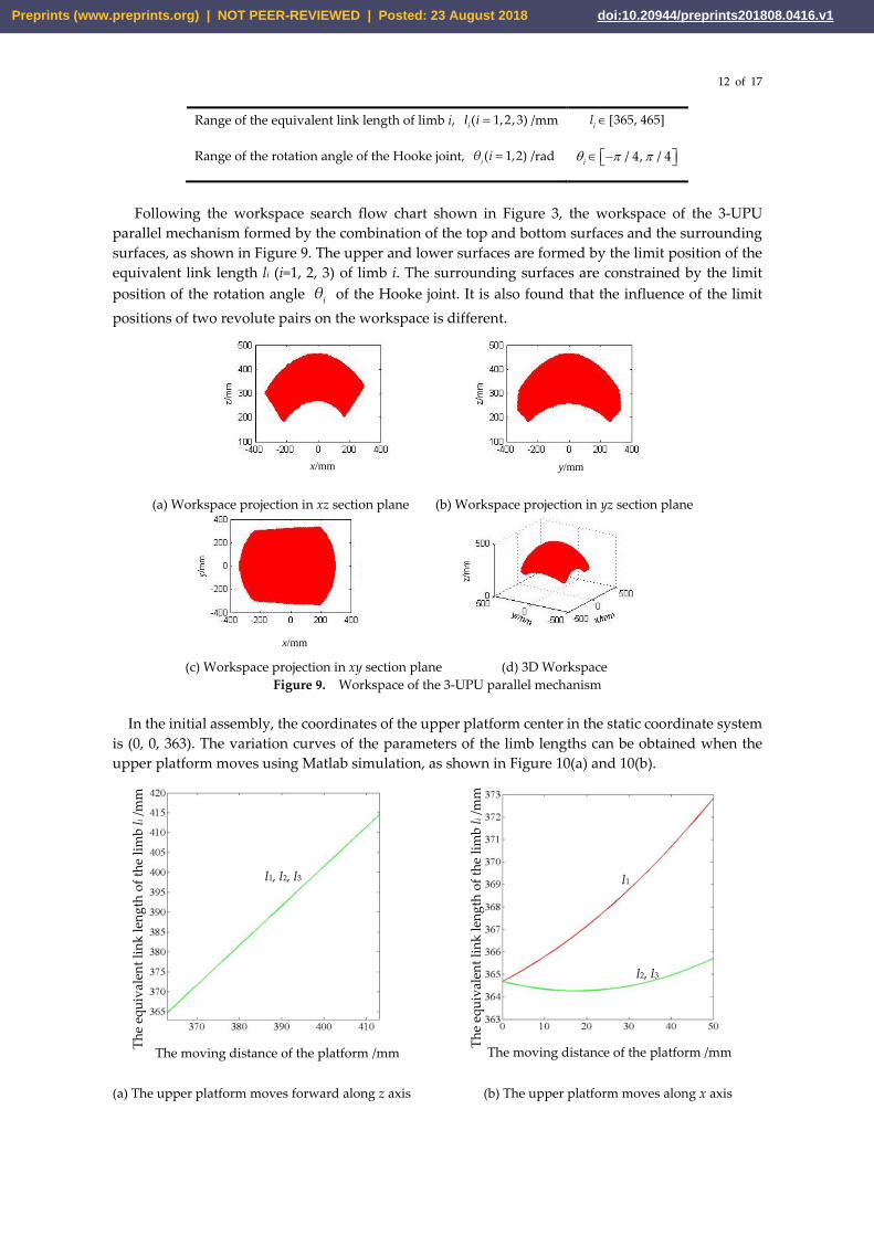
Following the workspace search flow chart shown in Figure 3, the workspace of the 3-UPU
parallel mechanism formed by the combination of the top and bottom surfaces and the surrounding
surfaces, as shown in Figure 9. The upper and lower surfaces are formed by the limit position of the
equivalent link length li (i=1, 2, 3) of limb i. The surrounding surfaces are constrained by the limit
position of the rotation angle iθ of the Hooke joint. It is also found that the influence of the limit
positions of two revolute pairs on the workspace is different.
(a) Workspace projection in xz section plane (b) Workspace projection in yz section plane
(c) Workspace projection in xy section plane (d) 3D Workspace
Figure 9. Workspace of the 3-UPU parallel mechanism
In the initial assembly, the coordinates of the upper platform center in the static coordinate system
is (0, 0, 363). The variation curves of the parameters of the limb lengths can be obtained when the
upper platform moves using Matlab simulation, as shown in Figure 10(a) and 10(b).
(a) The upper platform moves forward along z axis (b) The upper platform moves along x axis
x/mm y/mm
x/mm
The moving distance of the platform /mm The moving distance of the platform /mm
Th
e eq
uiv
alen
t li
nk
len
gth
of
the
lim
b l
i /m
m
Th
e eq
uiv
alen
t li
nk
len
gth
of
the
lim
b l
i /m
m
l1, l2, l3 l1
l2, l3
Preprints (www.preprints.org) | NOT PEER-REVIEWED | Posted: 23 August 2018 doi:10.20944/preprints201808.0416.v1

13 of 17
(c) The lower platform moves along z axis (d) The lower platform moves along x axis
Figure 10. Variation of the limb lengths when the upper or lower platform moves
When the lower platform moves, the moving and static coordinate systems exchange position.
The coordinate of the lower platform center in the static coordinate system is (0, 0, -363) mm. The
variation curve of parameters of each driving motor can be obtained from Equation (6), as shown in
Figure 10(c) and 10(d). From Figure 10, the equivalent link length of each limb li (i=1, 2, 3) varies
smoothly when the upper platform moves, that is, the displacement of each driving motor is stable.
When the upper platform is conducted as the moving platform, the static coordinate system is
established in the center of the lower platform. According to the robot’s gait planning, the maximum
stride lmax1 is 160mm, the starting point coordinate of the curve is (0, 363), and the ending point
coordinate is (160, 363). According to the workspace of the 3-UPU parallel mechanism, the maximum
obstacle height of the robot could cross is 80 mm, that is, the extreme point coordinate of the curve is
(80, 443). Substituting the coordinates of the starting point, the end point and the extreme point into
Equation (18), the trajectory equation of the reference point of the upper platform can be obtained,
= − + +20.0125 2 363z x x (19)
Taking the lower platform as the moving platform, the static coordinate system is connected to
the center of the upper platform. The maximum stride is 160mm. Substituting the starting point
coordinate (-60, -363), the ending point coordinate (0, -363), and the extreme point coordinate (-80, -
283) of the curve into Equation (18), the trajectory curve equation of the centroid of the reference point
of the lower platform can be obtained as follows.
= − − −20.0125 2 363z x x (20)
Following trajectory specified by Equation (20), walking along a straight line on flat terrain with
the robot was simulated in SolidWorks. A snapshot is shown in Figure 11. The variation of the
stability margin is shown in Figure 12. The stability margin is calculated by d=min{d1, d2, d3}, where
di, i=1, 2, 3 are the distances from G3 to three sides of the supporting triangle, as demonstrated in
Figure 5(a). As can be seen in Figure 12, the stability margin d is always larger than zero, thus static
walking stability is guaranteed.
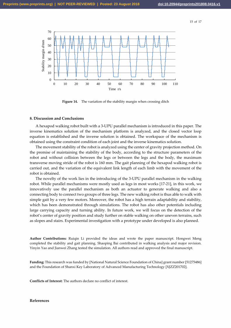
A simulation of walking on uneven terrain is shown in Figure 13, in which the robot walks over a
ditch. The step length is adjusted to fit both the ditch width and also the stability requirement. The
simulation shows that the robot can walk over the ditch stably, with the stability margin displaying
in Figure 14. Compared with Figure 12 for even terrain walking, the stability margin (SM) plot in
Figure 14 shows some differences. One is that the change of SM is not periodic, as the walking robot
has to adjust its stride in ditch crossing. Another difference is that, in Figure 14, the SM for some short
periods remains unchanged. This is because the two platforms do not move but only legs are
The moving distance of the platform /mm The moving distance of the platform /mm
Th
e eq
uiv
alen
t li
nk
len
gth
of
the
lim
b l
i /m
m
Th
e eq
uiv
alen
t li
nk
len
gth
of
the
lim
b l
i /m
m
l1, l2, l3
l1
l2, l3
Preprints (www.preprints.org) | NOT PEER-REVIEWED | Posted: 23 August 2018 doi:10.20944/preprints201808.0416.v1

14 of 17
extended to fit the terrain. It is noted that the SM in Figure 14 is always larger than zero too, which
guarantees a stable static walking.
Figure 11. Walking on flat terrain of 3-UPU hexapod walking robot
Figure 12. The variation of the stability margin when walking on flat terrain
Figure 13. Crossing a ditch of 140mm in depth and 350mm in width by the 3-UPU hexapod walking robot
0
20
40
60
80
0 5 10 15 20 25 30 35
Sta
bil
ity
mar
gin
d/m
m
Time t/s
l3
l2
l1
Preprints (www.preprints.org) | NOT PEER-REVIEWED | Posted: 23 August 2018 doi:10.20944/preprints201808.0416.v1
15 of 17
Figure 14. The variation of the stability margin when crossing ditch
8. Discussion and Conclusions
A hexapod walking robot built with a 3-UPU parallel mechanism is introduced in this paper. The
inverse kinematics solution of the mechanism platform is analyzed, and the closed vector loop
equation is established and the inverse solution is obtained. The workspace of the mechanism is
obtained using the constraint condition of each joint and the inverse kinematics solution.
The movement stability of the robot is analyzed using the center of gravity projection method. On
the premise of maintaining the stability of the body, according to the structure parameters of the
robot and without collision between the legs or between the legs and the body, the maximum
transverse moving stride of the robot is 160 mm. The gait planning of the hexapod walking robot is
carried out, and the variation of the equivalent link length of each limb with the movement of the
robot is obtained.
The novelty of the work lies in the introducing of the 3-UPU parallel mechanism in the walking
robot. While parallel mechanisms were mostly used as legs in most works [17-21], in this work, we
innovatively use the parallel mechanism as both an actuator to generate walking and also a
connecting body to connect two groups of three legs. The new walking robot is thus able to walk with
simple gait by a very few motors. Moreover, the robot has a high terrain adaptability and stability,
which has been demonstrated through simulations. The robot has also other potentials including
large carrying capacity and turning ability. In future work, we will focus on the detection of the
robot’s center of gravity position and study further on stable walking on other uneven terrains, such
as slopes and stairs. Experimental investigation with a prototype under developed is also planned.
Author Contributions: Ruiqin Li provided the ideas and wrote the paper manuscript. Hongwei Meng
completed the stability and gait planning. Shaoping Bai contributed in walking analysis and major revision.
Yinyin Yao and Jianwei Zhang tested the simulation. All authors read and approved the final manuscript.
Funding: This research was funded by [National Natural Science Foundation of China] grant number [51275486]
and the Foundation of Shanxi Key Laboratory of Advanced Manufacturing Technology [XJZZ201702].
Conflicts of Interest: The authors declare no conflict of interest.
References
0
10
20
30
40
50
60
70
0 10 20 30 40 50 60 70 80 90 100 110
Sta
bil
ity
mar
gin
d/m
m
Time t/s
Preprints (www.preprints.org) | NOT PEER-REVIEWED | Posted: 23 August 2018 doi:10.20944/preprints201808.0416.v1

16 of 17
1. Tedeschi, F.; Carbone, G. Design issues for hexapod walking robots. Robotics 2014, 3, 181-206.
2. Yang, F.; Ding, X.L.; Peng, S.J. Bio-control of a modular design robot-NOROS. Third ASME/IFToMM
International Conference on Reconfigurable Mechanisms and Robots, ReMAR, Beijing, China, 20-22 Jul. 2015; pp.
891-900.
3. Peng, S.J.; Ding, X.L.; Yang, F.; Xu, K. Motion planning and implementation for the self-recovery of an
overturned multi-legged robot. Robotics 2017, 35, 1107-1120.
4. Ma, Z.R.; Guo, W.Z.; Gao, F. Analysis on obstacle negotiation ability of a new wheel-legged robot. Machine
Design and Research 2015, 31, 6-10+15. (in Chinese)
5. Tsai, L.W. Kinematics of a three-DOF platform with three extensible limbs. In: Recent Advances in Robot
Kinematics, J. Lenarcic and V. Parenti-Castelli, eds., Kluwer Academic, London, 1996, pp. 401–410.
6. Gregorio R.D. Kinematics of the 3-UPU wrist. Mech. Mach. Theory 2003, 38, 253–263.
7. Ji, P.; Wu, H.T. Kinematics analysis of an offset 3-UPU translational parallel robotic manipulator. Robot. Auton.
Syst. 2003, 42, 117–123.
8. Han, C.; Kim, Jinwook; Kim, Jongwon; Park, F.C. Kinematic sensitivity analysis of the 3-UPU parallel
mechanism. Mech. Mach. Theory 2002, 37, 787–798.
9. Huang, Z.; Li, S.H.; Zuo, R.G. Feasible instantaneous motions and kinematic characteristics of a special 3-
DOF 3-UPU parallel manipulator. Mech. Mach. Theory 2004, 39, 957-970.
10. Wu, T.; Zhang, W.X.; Ding, X.L. Design and analysis of a novel parallel metamorphic mechanism. J. Mech.
Eng. 2015, 51, 30-37. (in Chinese)
11. Staicu, S.; Popa, C. Kinematics of the spatial 3-UPU parallel robot. U.P.B. Sci. Bull., Series D 2013, 75, 9-18.
12. Lu, Y.; Shi, Y.; Hu, B. Kinematic analysis of two novel 3UPU I and 3UPU II PKMs. Robot. Auton. Syst. 2008,
56, 296-305.
13. Staicu, S.; Popa, C. Dynamics of the translational 3-UPU parallel manipulator. U.P.B. Sci. Bull., Series D 2014,
76, 3-12.
14. Gregorio, R.D.; Parenti-Castelli, V. Mobility analysis of the 3-UPU parallel mechanism assembled for a pure
translational motion. IEEE/ASME International Conference on Advanced Intelligent Mechatronics, AIM, Atlanta,
GA, USA, 19-23 Sept. 1999; pp. 520-525.
15. Peng, B.B.; Li, Z.M.; Wu, K.; Sun, Y. Kinematic characteristics of 3-UPU parallel manipulator in singularity
and its application. Int. J. Adv. Robot. Syst. 2011, 8, 54-64.
16. Zhang, D.; Wei, B. Interactions and optimizations analysis between stiffness and workspace of 3-UPU robotic
mechanism. Meas. Sci. Rev. 2017, 17, 83-92.
17. Miao, Z.H.; Yao, Y. A.; Kong, X.W. A rolling 3-UPU parallel mechanism. Front. Mech. Eng. 2013, 8, 340–349.
18. Gu, Q.F. Kinematics of 3-UPU parallel leg mechanism used for a quadruped walking robot. In Proceedings of
2015 14th International Symposium on Distributed Computing and Applications for Business Engineering and Science,
DCABES 2015, Guiyang, China, 18-24 Aug. 2015; pp. 188-191.
19. Wang, M.F.; Ceccarelli, M.; Carbone, G. A feasibility study on the design and walking operation of a biped
locomotor via dynamic simulation. Front. Mech. Eng. 2016, 11, 144-158.
20. Sugahara, Y.; Endo, T.; Lim, H.; Takanishi, A. Design of a battery-powered multi-purpose bipedal locomotor
with parallel mechanism. IEEE/RSJ International Conference on Intelligent Robots and Systems, Lausanne,
Switzerland, 30 Sept.-4 Oct. 2002; pp. 2658-2663.
21. Wang, H.B.; Qi, Z.Y.; Hu, Z.W.; Huang, Z. Application of parallel leg mechanisms in quadruped/biped
reconfigurable walking robot. J. Mech. Eng. 2009, 45, 24-30. (in Chinese)
22. Hirakoso, N.; Terayama, J.; Yoshinaga, N.; Arai, T. A study on optimal formulation for multi-legged gait
robot with redundant joint. In Proceedings of the International Symposium on Micro-Nanomechatronics and Human
Science, Nagoya, Japan, 2017; pp. 1-6.
23. Sun, T.; Xiang, X.; Su, W.H.; Wu, H.; Song, Y.M. A transformable wheel-legged mobile robot: Design, analysis
and experiment. Robot. Auton. Syst. 2017, 98, 30-41.
24. Bai, S.; Low, K.H.; Zielinska, T. Quadruped free gait generation for straight-line and circular trajectories. Adv.
Robotics 2000, 13, 513-538.
25. Bai, S.; Low, K.H. Terrain evaluation and its application to path planning for walking machines. Adv. Robotics
2001, 15, 729-748.
26. Bai, S.; Low, K.H.; Teo, M.Y. Path generation of walking machines in 3D terrain. In Proceedings of the IEEE
International Conference on Robotics and Automation, Washington, DC, USA, 11-15 May 2002; pp. 2216-2221.
27. Gong, D.W.; Wang, P.; Zhao, S.Y.; Duan, Y. Bionic quadruped robot dynamic gait control strategy based on
twenty degrees of freedom. IEEE/CAA Journal of Automatica Sinica, 2018, 5, 382-388.
28. Li, M.T.; Jiang, Z.Y.; Wang, P.F.; Sun L.N.; Ge, S.S. Control of a quadruped robot with bionic springy legs in
trotting gait. J. Bionic Eng. 2014, 11, 188-198.
29. Matsuzawa, T.; Koizumi, A.; Hashimoto, K.; Sun, X.; Hamamoto, S.; Teramachi, T.; Sakai, N.; Kimura, S.;
Preprints (www.preprints.org) | NOT PEER-REVIEWED | Posted: 23 August 2018 doi:10.20944/preprints201808.0416.v1

17 of 17
Takanishi, A. Crawling motion and foot trajectory modification control for legged robot on rough terrain. In
Proceedings of the IEEE International Conference on Mechatronics and Automation, Takamatsu, Japan, 6-9 Aug.
2017; pp. 1976-1982.
30. Winkler, A.W.; Farshidian, F.; Pardo, D.; Neunert, M.; Buchli, J. Fast trajectory optimization for legged robots
using vertex-based ZMP constraints. IEEE Robot. Autom. Letters 2017, 2, 2201-2208.
31. Winkler, A.W.; Bellicoso, C.D.; Hutter, M., Buchli J. Gait and trajectory optimization for legged systems
through phase-based end-effector parameterization. IEEE Robot. Autom. Letters 2018, 3, 1560-1567.
32. Neunert, M.; Farshidian, F.; Winkler, A.W.; Buchli, J. Trajectory optimization through contacts and automatic
gait discovery for quadrupeds. IEEE Robot. Autom. Letters, 2017, 2, 1502-1509.
33. Zhao, Y.; Chai, X.; Gao, F. Obstacle avoidance and motion planning scheme for a hexapod robot Octopus-III.
Robot. Auton. Syst. 2018, 103, 199-212.
34. Oliveira, L.F.P.; Rossini, F.L. Modeling, simulation and analysis of locomotion patterns for hexapod robots.
IEEE Lat. Am. T. 2018, 16, 375-383.
Preprints (www.preprints.org) | NOT PEER-REVIEWED | Posted: 23 August 2018 doi:10.20944/preprints201808.0416.v1