fastcast: integration and application of rapid …
TRANSCRIPT

FASTCAST: INTEGRATION AND APPLICATION OF RAPID PROTOTYPING AND COMPUTATIONAL SIMULATION TO INVESTMENT
CASTING
M.C. Maguire, M.D. Baldwin and C.L. Atwood Sandia National Laboratories
Albuquerque, NM 87 185-1 134
ABSTRACT
The emergence of several rapid prototyping & manufacturing (W&M) technologies is having a dramatic impact on investment casting. While the most successful of the rapid prototyping technologies arc almost a decade old, relatively recent process advances in their application have produced some remarkable success in utilizing their products as patterns for investment castings. Sandia National Laboratories has been developing highly coupled experimental and computational capabilities to examine the investment casting process with the intention of reducing the amount of time required to manufacture castings, and to increase the quality of the finished product. This presentation will begin with process aspects of W & M pattern production and handling, shell fabrication, burnout, and casting. The emphasis will be on how the use of Stereolithography (SL) or Selective Laser Sintered (SLS) patterns differs from moE traditional wax pattern processes, Aspects of computational simulation to couple design, thermal analysis, and mold filling will be discussed. Integration of these topics is probably the greatest challenge to the use of concurrent engineering principles with investment casting. Sandia has conducted several experiments aimed at cabrating computer codes and providing data for input into these simulations. Studies involving materials as diverse as stainless steel and gold have been conducted to determine liquid metal behavior in molds via real time radiography. The application of these experiments to predictive simulations will be described.
KEY WORDS: Investment Casting, Rapid Prototyping, Computational Simulation
1. INTRODUCTION
Sandia National Laboratories (SNL) is a multi-program laboratory operated for the U.S. Department of Energy. 4s an engineering laboratory responsible for the design and manufacture of a variety of prototype devices, mostly electrical and electromechanical, a need continually exists for production in a more timely and efficient manner. Over the years, our manufacturing processes have evolved from labor-intensive, manually operated machine tools to computer-aided machining centers and &-feed electrical discharge machines. Despite these advances in computer numerically controlled (CNC) machining, many components at SNL still required extensive and time-consuming fabrication and assembly. For these reasons the lab began investing in W & M technologies in 1990. Initially used for production of polymer-based parts used for design validation, it became increasingly clear that the value of rapid prototyping would be augmented if their products could readily be used as patterns for investment casting. With the lead time and cost for tooling to produce wax investment casting patterns often prohibitive, W & M patterns used directly in investment casting dramatically reduced the time for fxst item delivery. Additionally, the time savings became a deciding factor in the successful application of many components because they could be produced, tested, and re-designed faster than it traditionally took to acquire a wax injection tool. When married With investment
1 1 4
This work performed at Sandia National Laboratories is supported by the U.S. Department of Energy under contract number DE-ACO4-94AL85000.
DISTRIBUTiBN OF Ttfos

DISCLAIMER
Portions of this document may be illegible in electronic image products. Images are produced from the best available original document.

DISCLAIMER
This report was prepared as an account of work sponsored by an agency of the United States Government. Neither the United States Government nor any agency thereof, nor any of their employees, makes any warranty, express or implied, or assumes any legal liability or responsibility for the accuracy, completeness, or use- fulness of any information, apparatus, product, or process disclosed, or represents that its use would not infringe privately owned rights. Reference herein to any spe- cific commercial product, process, or service by trade name, trademark, manufac- turer, or otherwise does not necessarily constitute or imply its endorsement, mom- mendation. or favoring by the United States Government or any agency thereof. The views and opinions of authors expressed herein do not necessarily state or reflect those of the United States Government or any agency thereof.

casting, RP&M has seen some dramatic benefits on the production of cast metal parts.
Sandia began producing investment cast prototypes in 1985. Cast primarily from aluminum or stainless steel, the fmt items were produced months after the design had been finalized due to the time to procure the wax injection tool. Once the tool was available, further time was used to determine proper methods of gating the part to produce a defect-free casting. Often this required several gating and rigging design iterations. In an effort to speed the design and fabrication process while awaiting the wax injection tool, several processes were used. The first method used hand manufactured patterns from sheet wax formed to closely resemble the component. While crude in appearance and far from the dimensional accuracy required, these items usually served to evaluate mechanical behavior (vibration, shock and crush tests), but little else. The next method used CNC machining to produce patterns from blocks of wax. While more accurate, the time associated with machining of wax was not greatly less than if a metal part had been machined. However, the production of a cast component was generally considered valuable to aid in validating the performance of the final cast design. Not until RP&M technologies began to produce patterns quickly, with sufficient accuracy, and able to be processed in mold fabrication like wax patterns were they considered competitors to CNC machining for rapid prototype production. Not only have RP&M patterns lived up to this expectation, for SNL there has been little need for traditional wax injection tools for over two years. This has been accomplished by using the patterns directly from RP&M machines to produce castings in lot sizes of less than about 20 units.
Not only have the fabrication technologies for investment casting been dramatically impacted, the ability to simulate the casting process has also seen pressure from RP&M technologies. As mentioned, the time to produce castings from RP&M patterns has been cut dramatically. However, when relying on W&M for patterns the more traditional methods used in investment casting to conduct gating trials with several wax patterns is not possible. Hence, a strong desire for more reliable, user-friendly, and accurate computer simulations of the casting process has become more important than ever to help solve the more difficult casting problems. For this reason, SNL began a program called FASTCAST to help integrate computational technologies and RP&M technologies into investment casting. In the following sections, a review of the W&M processes and their impact on investment casting will be discussed. A description of the FASTCAST project with its major goals and accomplishments will also be presented.
2. INVESTMENT CASTING AND RAPID PROTOTYPING
2.1 The Znvestment Casting Process casting, is regarded as a precision casting process to fabricate metal parts from almost any alloy. Although its history lies to a large extent in the production of art, the most common use of investment casting in more recent history has been the production of components requiring complex, highly toleranced, often thin-section castings of high quality. While a complete description is beyond the scope of the discussion here, the salient features of the process will be briefly described, with emphasis on the how RP&M has been incorporated.
Unlike sand casting where a single pattern can serve to produce a large number of molds, a new pattern is required for every investment casting. These patterns, typically produced in injection molding machines, are made from wax specifically formulated for this use. Once a wax pattern is produced, it is assembled with other wax components to form a metal delivery system, called the gate and runner system. The entire wax assembly is then subsequently dipped in a ceramic slurry, and covered with a sand stucco coat and allowed to dry. This dipping and stuccoing process is repeated until a shell of approximate 6 to 8 mm (1/4 to 3/87 is applied. Once the ceramic has dried, the entire assembly is placed in a steam autoclave to remove most of the wax. After autoclaving, the remaining amount of wax that soaked into the ceramic shell is burned out in an air furnace. At this point the shell is empty. It is then usually pre-heated to a specific temperature, and filled with molten metal. The hot mold assists with filling of intricate shapes and thin sections. Once the casting has cooled sufficiently, the shell is chipped from the mold, and the desired casting cut from the gates and runners. As can be seen,
Investment casting, often called lost wax

the process requires that a pattern be destroyed for each metal casting produced A slightly more detailed step by stem description of the process is presented in Table 1.
Table 1: Stem to Produce an Investment Castinq
Design Casting Design Gating System Design & Procure Die Produce Wax Part Produce Gatemunner Assembly Fabricate Shell Dry Shell DeWaX
9) Fire Shell 10) Pour Casting 1 1) Remove Shell 12) Remove Gates 13) Hot/Cold Straighten 14) Heat Treat 15) Inspect 16) Ship
In a direct sense, the onset of RP&M processes has had an impact on the process by eliminating only a few of the steps listed above, namely the design and procurement of the wax injection die. However, it has b n the cost and the time associated with manufacture of this tool that has contributed substantially to the perception of investment casting as an expensive and time consuming process, not at all suited for rapid production of prototypes. In the past, a complex injection tool for a structural casting in the 5 lb range could cost more than $50,000 and require 30 to 50 weeks of lead time. Compounding this problem was that more often than not, the "final" design was in fact not so final. Changes to the die before it ever left the toolmaker were not uncommon. With the advent of RP&M processes to shorten the time required to make the first patterns from several months to often only a day, the investment casting industry is experiencing some remarkable changes that are slowly changing commonly held opinions regarding its agility.
2.2 Implementation of RP&M in Investment Casting Although the primary pattern material for traditional investment casting is wax, other materials have been used for specialized applications. Hence, substituting something other than wax for the pattern is not unique, but the changes to the process that this entails presents some unique challenges to the foundry. The use of SL and SLS as expendable patterns at SNL is described in the sections that follow.
2.2.1 Stereolithography (SL) 250) has been in operation at SNL since 1990 as a design tool to facilitate the prototyping process. The initial use of the SLA-250 was to quickly fabricate prototypes from three- dimensional solid models. Typical uses of the prototype models were for proof-of-concept demonstrators, in mechanical design reviews, for interference fit-checks, and as visual aids for other methods of manufacturing. While the process was not a replacement for traditional machining, it represented another tool used to speed up the product development cycle, and offered advantages to improve the agility with which designs were improved or modified. These advantages included unattended operation, ease of fabricating complex parts, increased design flexibility, reduced lead times and fabrication costs, and more efficient design iterations.
A Stereolithography apparatus (3D Systems model SLA-
The evolution of Stereolithography (SL) has brought about significant changes in application of RP&M technology. Parts produced with SL have matured from "show-and-tell" models to high quality expendable patterns for investment casting, as soft tooling for sand casting. In most cases, early efforts to use solid SL patterns for investment casting at SNL failed using the traditional shell casting method. Whereas wax patterns would melt and soak into the shell prior to expanding and cracking the shell in thermal dewaxing, solid polymer-based SL patterns do not melt. Thermal expansion of solid acrylic patterns is sufficient to fracture ceramic shells during dewax and burnout as to render the shells useless. Although some manufacturers employing solid mold investment casting were capable of producing crack-free molds, SNL decided to pursue shell molding as its sole method for investment casting.

2.2.2 Quickcast Patterns in the Investment Casting Process Recent advances in process development and in the implementation of Quickcast' epoxy resin and software have had a significant impact on applications for the SL process. Using the QuickCast build style and epoxy resin, it is now possible to build semi-hollow patterns for investment casting. The combination of build style and epoxy resin ameliorate the problem of thermal expansion during burn-out by reducing the amount of resin in the pattern. With proper treatment, the semi- hollow patterns generate much less stress on the ceramic shell. As with any new manufacturing process, there are many variables associated with using QuickCast patterns as a replacement for traditional wax patterns for investment casting. Sandia is currently in the iterative process of defining the sequential steps necessary to produce good castings consistently using QuickCast Patterns. Our experience indicates that process modifications from traditional lost-wax processing techniques such as pattern preparation for dipping, bum-out cycles, and mold venting are required to produce a quality casting. While these recommendations are not meant to be construed as the only successful methods for using QuickCast patterns, practice has shown that our greatest successes have been with following procedures.
Our experiences with the semi-hollow QuickCast patterns can be characterized by first examining the steps in their handling, then in how the mold is dewaxed and burned out. Most patterns require some hand work to prepare them for use as patterns. Sanding of stepped surfaces and removal of support structures are typically part of the process stream whether the SL parts are used as patterns or not. However, it is essential that any sharp comer or thin edges from a support structure be removed to minimize stress on the shell during burn-out. Being constructed from interlocking hollow cells allows the pattern to be drained, but all holes in the pattern must be filled prior to dipping. The reason for this is two-fold. First, any holes in the pattern will allow ceramic slurry to flow into the pattern. This will obviously result in extensive inclusions in the casting. Secondly, the dewax and bum-out step can create large gas pressures inside the pattern. While the polymer in the pattern interior has been removed, the presence of air in the sealed pattern can be sufficient to cause a ballooning effect that is sufficient to crack the shell. This expansion is eliminated by careful use of vents in the pattern, but any holes not vented properly have caused localized shell failure. Hence, before any gating system is added to the pattern, all holes intentionally added to assist in draining must be filled. In addition, any holes that resulted from sanding through the surface skin must be also be patched Identification of holes is most easily made by pressure or vacuum testing the pattern.
Once the pattern has been fully prepared, it can be attached to a gating system. Whereas most investment casters will design the wax runners and gates to facilitate draining the melted wax out of the mold in the autoclave (usually in a steam autoclave), the use of Quickcast patterns places an additional requirement on the wax distribution system. As mentioned, the patterns must be vented to the atmosphere. This is critical during the early stages of bum-out, prior to thermal decomposition of the polymer. Venting of the pattern can be accomplished several ways. Hollow gates and runners can be constructed and used to provide an unintempted gas bath back up to the pouring cup. The hollow runner can also be vented to atmosphere at a location prior to attaching to the pouring cup. Individual vents, placed directly on the pattern can also be used. An example of such a vent is shown in Fig. 1. The pattern is perforated as shown in Fig. l(a), then the wax vent is placed over the hole, Fig. l(b). As the shell is constructed, the wax vent is kept exposed so that during the later bum-out, sufficient air can circulate in the mold However the pattern is vented, it is critical to perforate the pattern at the location of the gate or vent, and then seal the wax gate or stub directly over the hole. While it may seem contrary to previous advice that demanded that all holes in the pattern be sealed, if the pattern is not vented directly at specific locations, then shell cracking via the ballooning effect is likely. The holes used to drain excess resin from the pattern have to be sealed because generally they are not where the gates or vents will be located, and unless all drain holes are sealed then other smaller pinholes cannot be located by vacuum or pressure testing. By perforating the outer skin of the pattern, and then sealing a wax gate or vent over the hole, the penetration of the pattern by ceramic slurry is precluded.
IQuickCast is a trademark of 3D Systems, Inc., Valencia CA

Figure 1: Sequence of venting a Quickcast pattern in a small localized area: (a) pre-drilling of holes to assure venting of the pattern during bum-out, and (b) placement of a wax stub to form the vent and cover the holes prior to dipping in ceramic.
If the pattern is vented by hollow gates and runners, then it is important to make sure that a continuous gas path exists from the every isolated hollow section of the Quickcast pattern, through the gating system, to the atmosphere. For example, using preformed hollow runner systems is of no value if they are sealed at the end. In fact, the trapped air in thin hollow wax runners can often crack shells if not vented. If solid gates and runners are used, then placement of small wax stubs directly over perforations in the patterns can produced the desired venting, but these vents must be exposed to atmosphere prior to dewaxing, and then patched with ceramic mortar following the final bum-out. Most foundries prefer not to have large open areas to patch since the likelihood for adding small inclusions increases.
Most slurry systems for facecoats contain surfactants to promote wetting of the slurry on the wax. However, it has been observed with resin patterns from SL that the sluny may not adhere to pattern as well as with a wax pattern. The resulting surface on the casting may have an orange peel effect, but is generally not as severe as defects produced from gross facecoat delamination. The cast surface finish resulting from this defect is unacceptable. While there have been no published studies to determine what, if any, modifications to the slurry would be necessary to preclude this effect, it would seem to be prohibitive to have a separate slurry composition solely for SL patterns. The solution at SNL to this pattern de-wetting problem has been to lightly spray the SL pattern with a aerosol glue to promote facecoat adherence. The spray glue is applied just prior to dipping and allowed to dry.
I t has been our experience that whether or not shell cracking is a large or small problem is strongly dependent on the type of shell system being used. Most foundries experience small amounts of shell cracking even in the autoclave, usually the result of not being able to properly drain and vent wax from certain regions. The cracking in these cases is usually readily patched with ceramic mortar with no deleterious effects on the subsequent casting. That the RP&M patterns will produce higher stresses on the shell is generally accepted, but whether or not i t is sufficient to cause catastrophic cracking varies with each ceramic system. SNLs traditional shell system consists of two primary coats of aluminosilicate/colloidal silica slurry with silica stucco, followed by a fused silicalcolloidal silica backing slurry and fused silica stucco. A tot:il of 6 backing coats is used for traditional wax patterns. When initial shell cracking was encountered with RP&M patterns, the number of backing coats was increased to 8, and chopped ceramic fibers (typically 3M Nextel) were incorporated into the fourth backing coat. This improved the shell strength, verified with mechanical testing, to the extent that shell cracking was largely eliminated with effective pattern venting. Other methods observed in foundries consist of incorporating chopped stainless steel wire, or using chopped stainless steel wool. Our testing of chopped steel fibers indicated that is was almost as effective at improving shell strength as the ceramic fibers.
While the traditional method of dewaxing by steam autoclave is considered the most economical and environmentally friendly method for investment casting, it has become increasingly clear that it's use is problematic for RP&M patterns. Autoclaving is designed to

remove the majority of the wax in the mold, and subsequent burn-out used to remove the remaining wax. Even with the venting methodologies described previously, SNL's experience with autoclaving under several different temperatures and pressures has yielded no consistent method to eliminate shell cracking. At pressures as low as 15 psig and temperatures of only 220"F, shell cracking was still observed. These lower temperature cycles were used with completely hollow gating systems and generally removed most of the wax, but increased cycle times. For this reason, the consensus at SNL, and indeed in industry, is that flash-fire dewaxing is the method of choice for RP&M pattern bum-out. Unfortunately, the reason that flash-fire dewaxing was abandoned for autoclaving many years ago was that the choking amount of smoke was eliminated by removing the wax with steam prior to final burn-out. While some might consider a return to flash-fie dewaxing a giant leap backwards, these furnaces have improved dramatically in recent years by addition of afterburners owing to strict air quality standards adopted by most states.
While flash-fire dewaxing may be the ideal method to dewax and burn-out W&M molds, it is also recognized that most foundries could not readily invest in such a furnace solely to process RP&M molds. As a result, the practice at SNL prior to adopting newer generation flash-fire dewaxing, was to eliminate as much wax in the mold by the use of hollow gates and runners, and then using heat guns or oxy-acetylene torches to remove as much wax as possible prior to final burn out. Even so, the pattern material itself can generate a significant amount of combustible gases, so propane or gas-fired furnaces are highly recommended to minimize the amount of smoke during final burn-out. The necessity for venting the pattern and mold is also important once the change of shell cracking has passed during the burn-out cycle. In order to ensure better air flow through the shell, a reasonable number of vents is recommended.
Once burned out, the mold will generally need to be patched. Any vents introduced earlier will need to be sealed with ceramic mortar. If the hollow gates and runners were vented up through the pour cup, then it would be possible to go directly to the casting operation from burn-out. However, our experiences are limited since it is necessary to cool our molds after burn-out for inspection and patching. Individual choices for each foundry may depend on the type of shell system being used, and its tolerance for repeated thermal cycling as to whether or not separate burn-out and casting pre-heat cycles can be used. Bum-out cycles for the patterns tend to be higher than traditional processing. For example, burn-out of traditional autoclaved molds at SNL was conducted at 700°C (130OOF) for 4 hours, but for SL patterns the burn-out temperature is usually 760°C (1400°F) or higher for periods extending to 8 hours or more. Experience with temperatures as high as 1 150°C (2100°F) indicates that patterns can be fully combusted with little or no ash residue in as little as 2 hours. However, ceramic shells containing fused silica undergo a crystallization phase transformation at temperatures above 870°C (16oooF) which causes severe shell cracking upon cooling to room temperature.
Once the mold has been filled with metal, there is virtually no difference from the traditional processing with maybe one exception. If the shell has been reinforced with fiber or is thicker that normal, its removal may be slightly more difficult than normal.
2.2.3 Selective Laser Sintering introduced by the University of Texas, Sandia researchers became involved in the SLS Technical Associates Group to follow and help guide the development of the SLS technology. This process was inherently attractive to investment casters because it could produce patterns directly from investment casting wax. As a result, the type of process modifications for SL would not be required. In 1991 Sandia used a segment of the an investment casting called a firing set housing to benchmark different RP&M systems for fabricating patterns for investment casting. Subsequently, in March 1992 Sandia became a Beta test site for a pre- production Sinterstation2 2000 Selective Laser Sintering machine. Our efforts were focused on fabricating the best wax patterns possible using the SLS process. At that time, the SLS process produced the most accurate patterns for investment casting using traditional investment casting wax. Using the SLS process, we were able to demonstrate the value of using rapid prototyping processes to fabricate prototype patterns for investment casting. At the end of the Beta
When the concept of Selective Laser Sintering was
Sinterstation is a registered trademark of DTM Corp., Austin, TX

program, Sandia purchased a Sinterstation 2000 SLS production machine. At that time, a decision was made to change materials from wax to polycarbonate for making investment casting patterns. The advantages of using polycarbonate material are faster build time, more robust parts, dimensional stability, and the absence of a support structure during the build process. Sandia is currently developing techniques required to make investment casting molds from polycarbonate patterns. These are described in the following discussion.
2.2.4 SLS Patterns in the Investment Casting Process While the wax patterns produced in SLS could be processed identically to traditional injection molded wax patterns, the reality of handling and finishing these fragile made their use difficult. This problem was compounded in thin section parts. Eventually, the introduction of polycarbonate to SLS made the handling and finishing problems much less difficult. The discussion here will be focused on the use of polycarbonate patterns.
The polycarbonate patterns constructed in the machine are generally speaking rather porous. Exact levels of porosity for the patterns vary with build parameters, but is generally not a critical factor in using the patterns for investment casting. Since the patterns are porous, they must be sealed prior to dipping in ceramic slurry. Although the slurry will not seep into the polycarbonate as it would through a hole in a Quickcast pattern, the colloidal silica binder in the facecoat seeps into the pattern weakening the primary coats of the ceramic shell, and the surface finish is unacceptable rough. Hence, the standard procedure for using these patterns has been to soak the pattern in seal wax (an investment wax used for dipping gating systems to create a smooth surface) for enough time to allow the wax to thoroughly penetrate the polycarbonate. Although the wax is molten and the pattern heats to the temperature of the wax (typically 19OoF), negligible distortion has been observed in the patterns.
Upon removing the patterns from the wax, the excess wax is removed by shaking or spinning. The patterns are cooled back to room temperature. Any excess wax is scraped from the surface. A heat gun is then used to lightly melt the wax on the surface of the pattern. This melting "sweats" the wax up to the surface and tends to smooth low areas between polycarbonate particles. Extensive use of the heat gun will bring up too much wax to the surface, reducing dimensional accuracy of the pattern. Finally, the patterns are sanded or finished with an abrasive pad.
As with SL patterns, autoclaving tends to produce shell cracking so its use is not recommended. Direct bum-out is again the dewaxing method of choice. Since the patterns are not hollow, placement of gates and care in sealing holes is not an issue with polycarbonate SLS patterns, but placement of vents is again important. Vents are routinely placed on patterns similarly to that shown in Fig. 2. The vents serve to provide air access to the pattern as it combusts to minimize the amount of ash or carbonaceous residue in the mold. Unlike resin based SL patterns, polycarbonate is a thermoplastic and will tend to run out of the mold in a manner similar to wax. It is substantially more viscous than wax, and is not removed as quickly as wax. In most of the patterns burned out at SNL, about half of the polycarbonate runs out of the mold, with the remainder subject to combustion in the mold. The material that remains in the mold, especially in areas where it may collect or puddle, has been shown to attack shells. While the exact mechanism is uncertain. it is suspected that like wax, the polycarbonate may to some extent soak into the shell, and then cause delamination of facecoat layers. The resulting surface of the casting has an appearance of a cracked desert lake-bed. Depending on orientation of the pattern, addition of vents in these re-entrant areas to assist with drainage is encourages. Burn-out times with polycarbonate patterns tend to be longer than with SL QuickCast patterns. A typical bum-out cycle of consists of soaking at 1400OF until the primary combustion is complete, followed by continued soak for 2-8 hrs at 1400OF to remove all ash residue from the mold. If possible, excess air during the burn-out will help with removal of the ash residue in the mold

Figure 2: SLS gating system.
?T
i polycarbonate pattern with several vents attached to both the Vents provide air circulation during dewaxing and burnout.
patterns and the
3. COMPUTATIONAL SIMULATION IN INVESTMENT CASTING
As mentioned previously, the reduction in prototype (fmt article) delivery time brought on by RP&M technologies coupled with investment casting has put increasing pressure on computational simulation of the casting process. Whereas a gating geometry could be designed by several casting iterations with different gating systems on several wax patterns, such conditions do not exist for patterns produced in RP&M. The foundry must design and produce a single good casting the first time from the only pattern that exists. Subsequently, fast, accurate and easy-to-use casting simulation software is being increasingly demanded by more foundries.
Simulation of the casting process presents complex challenges due to the number of physical processes encountered. Investment casting, relative to other processes like sand casting, presents potentially the most troublesome conditions for simulation. Often the complex and thin-walled geometry makes the simulation cumbersome owing the fineness of detail required in just the computational grid. Furthermore, it has been our experience that investment casting simulations are particularly sensitive to input conditions such as interface heat transfer coefficient and surface boundary conditions. Other casting process simulations seem to be more tolerant to changes in some of these parameters without severely degrading accuracy of results.
In general, for a simulation to provide a realistic assessment of investment casting in order to predict final part soundness and geometry, the following elements must exist in the analysis:
i) mold cooling prior to metal entry ii) coupled thermal and fluid flow simulation during mold filling iii) coupled thermal and compositional evolution during metal solidification iv) micro- and macrostructural evolution prediction during solidification and
cooling v) proper partitioning of radiative, convective, and conductive heat components
in the previous three elements vi) mold and metal mechanical response to anisothermal conditions
3 _. while this list is not meant to be complete, it points to the difficulty with simulating even the -AP, &--la ;,.,ao+mno+ ,...-L-- ---LI---- T- c- - . . .
of the complexity described above. The only reasonable approach to incorporating casting simulation at an engineering level has been to reduce the problem in most cases to assume instantaneous mold filling and to solve primarily for the thermal response in the metal and shell. While some of the most advanced commercial casting software can provide functionality to incorporate all of the above requirements, the reality is that most users do not have access to enough empirical data from which the codes can provide accurate predictions.
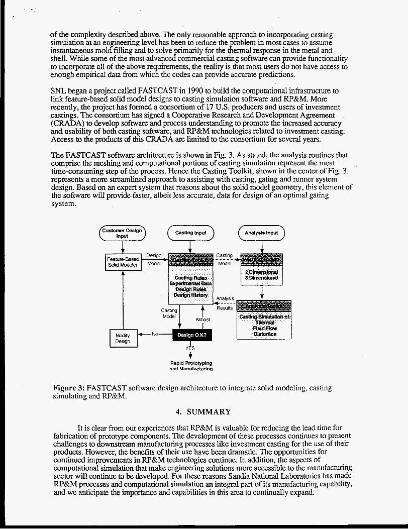
SNL began a project called FASTCAST in 1990 to build the computational infrastructure to link feature-based solid model designs to casting simulation software and W&M. More recently, the project has formed a consortium of 17 U.S. producers and users of investment castings. The consortium has signed a Cooperative Research and Development Agreement (CRADA) to develop software and process understanding to promote the increased accuracy and usability of both casting software, and RP&M technologies related to investment casting. Access to the products of this CRADA are limited to the consortium for several years.
The FASTCAST software architecture is shown in Fig. 3. As stated, the analysis routines that comprise the meshing and computational portions of casting simulation represent the most time-consuming step of the process. Hence the Casting Toolkit, shown in the center of Fig. 3, represents a more streamlined approach to assisting with casting, gating and runner system design. Based on an expert system that reasons about the solid model geometry, this element of the software will provide faster, albeit less accurate, data for design of an optimal gating system.
+ Rapid Prototyping and Manufacturing
Figure 3: FASTCAST software design architecture to integrate solid modeling, casting simulating and RP&M.
4. SUMMARY
It is clear from our experiences that W&M is valuable for reducing the lead time for fabrication of prototype components. The development of these processes continues to present challenges to downstream manufacturing processes like investment casting for the use of their products. However, the benefits of their use have been dramatic. The opportunities for continued improvements in RP&M technologies continue. In addition, the aspects of computational simulation that make engineering solutions more accessible to the manufacturing sector will continue to be developed. For these reasons Sandia National Laboratories has made RP&M processes and computational simulation an integral part of its manufacturing capability, and we anticipate the importance and capabilities in this area to continually expand.

ACKNOWLEDGMENTS
The authors gratefully acknowledge the countless efforts by SNL staff with the preparation of the information presented here. Special thanks go to B. Pardo, E. Bryce, G. McCarty, L. Gonnsen, and S. Giron. This work performed at Sandia National Laboratories is supported by the U.S. Department of Energy under contract number DE-AC04-94AL85000.