fast setup - honeywell productivity and workflow...
TRANSCRIPT

Fast Setup
Quick Reference Guide

Intermec Technologies Corporation6001 36th Avenue WestP.O. Box 4280Everett, WA 98203-9280
U.S. service and technical support: 1-800-755-5505U.S. media supplies ordering information: 1-800-227-9947
Canadian service and technical support: 1-800-688-7043Canadian media supplies ordering information: 1-800-268-6936
Outside U.S. and Canada: Contact your local Intermec service supplier.
The information contained herein is proprietary and is provided solely for the purpose ofallowing customers to operate and/or service Intermec manufactured equipment and is not tobe released, reproduced, or used for any other purpose without written permission of Intermec.
Information and specifications in this manual are subject to change without notice.
1998 by Intermec Technologies CorporationAll Rights Reserved
The word Intermec, the Intermec logo, JANUS, IRL, TRAKKER, Antares, Adara, Duratherm,EZBuilder, Precision Print, PrintSet, Virtual Wedge, and CrossBar are either trademarks orregistered trademarks of Intermec.
Throughout this manual, trademarked names may be used. Rather than put a trademark( or ) symbol in every occurrence of a trademarked name, we state that we are using thenames only in an editorial fashion, and to the benefit of the trademark owner, with no intentionof infringement.

Contents
iii
ContentsAbout Fast Setup 5
Network Adapter Cards 5Using Online Help 6
Step 1 - Complete the Worksheets 8
Step 2 - Set Up the Controller 8Power Cord 9Monitor 9Keyboard 9Mouse 9
Step 3 - Install the Controller 10Connecting to Your Data Collection Network 10Connecting to Your Host Environment 10Turning on the Controller 11About the Fast Setup Main Menu 12
Step 4 - Set the System Parameters 13
Step 5 - Set Up the Data Collection Environment 16Configuring an RF Card for Your Network 18Configuring a UDP Plus Network 19Configuring an Intermec Controller for Your Network 21Verify Your Data Collection Environment 21
Step 6 - Set Up the Host Communications Environment 24Ethernet Adapter Card 25Token Ring Adapter Card 27Coaxial Adapter Card 27Twinaxial Adapter Card 28SDLC Adapter Card 29
Step 7 - Configure the Host Environment Parameters 30Setting Up Telnet Terminal Emulation 31Setting Up 5250 SNA Terminal Emulation 36
Fast Setup Quick Reference Guide
iv
Setting Up 3270 SNA Terminal Emulation 41Setting Up Peer-to-Peer Links 47Setting Up a Terminal Session 53Verify Your Host Connection 65
Step 8 - Start the Controller 66
Where Do You Go From Here? 68
IndexI
Fast Setup Quick Reference Guide
5
This quick reference guide explains how to use Fast Setup to configure the Model200 Controller.
About Fast SetupUse Fast Setup to configure the Model 200 Controller quickly so you can
• demonstrate the controller.
• verify your network environment is functioning.
• learn about the controller and its graphical user interface (GUI) beforeusing Advanced Setup.
• do preliminary configuration for your data collection network.
Fast Setup uses default values for many of the configuration parameters andit only prompts you to enter a few required parameters.
When you configure the controller in Fast Setup, you set up a hostconnection, define your Intermec equipment, and set up the routing for datato the correct destination.
Network Adapter CardsDepending on the upline network cards in your controller, you can connectthe controller to
• any TCP/IP host on an Ethernet or token ring network that supportsTelnet.
• any SNA host on a token ring, twinaxial, coaxial, or SDLC network thatsupports APPC and 5250 or 3270 terminal connections.
Note: You can also set up VT, ANSI, 3270, and 5250 terminal sessions, but youcan only start these terminal sessions on your controller. Fast Setup does not letyou configure screen mapping.
Depending on the downline cards in your controller, you can connect thecontroller to
• Intermec’s 900 MHz RF network.
• Intermec’s 2.4 GHz RF network (UDP Plus) through access pointsconnected to the Ethernet network.

Fast Setup Quick Reference Guide
6
The controller also has two serial ports (COM1 and COM2) that let youconnect external Intermec controllers for CrossBar™ network support, a9180 Network Controller, an uninterruptable power supply, or an externalmodem.
Using Online HelpThe Model 200 Controller includes online help that provides descriptions ofthe toolbars, dialog boxes, and options. Help also includes step-by-stepprocedures and some background information.
To get help
• Choose the Help button.
The Help window opens and displays the topic for the toolbar or dialog boxyou were using. If you requested Help from the main menu, the GettingStarted topic appears. You can resize and move your Help window to seemore of a topic at one time or to see more of the configuration window.Colored or underlined text indicates that you can jump to topics.
To jump to another help topic
• Double-click the topic name. Or, press Tab until the topic is highlighted,and then press Enter.
To use the help buttons
• Choose Previous or press Esc to jump to the previous topic.
• Choose Search to search for Help on a specific word or phrase.
• Choose Index to look up a topic in the Index.
• Choose Contents to look up a topic in the Contents.

Fast Setup Quick Reference Guide
7
Connecting the Controller to Your Data Collection Network
Ethernet
RS- 485
RS
-232
RS-232Model 200Controller
J2010
9445
JG2020
JG2050
J2050
9189
JR20203400
900 MHz
2.4 GHz
0200-024
CrossBar
3400
Host
9181
T2425
9154
Access Point
Fast Setup Quick Reference Guide
8
Step 1 - Complete the WorksheetsBefore you use Fast Setup, complete the relevant worksheets in Appendix Ein the Model 200 Controller User’s Manual. You will need to obtain much ofthis information from your network administrator. After you havecompleted the worksheets, you will have all the information you need torun Fast Setup and to configure the controller successfully.
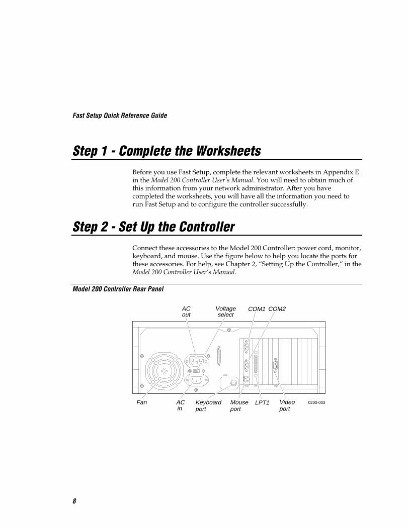
Step 2 - Set Up the ControllerConnect these accessories to the Model 200 Controller: power cord, monitor,keyboard, and mouse. Use the figure below to help you locate the ports forthese accessories. For help, see Chapter 2, “Setting Up the Controller,” in theModel 200 Controller User’s Manual.
Model 200 Controller Rear Panel
110V
MOUSE
KEYBD
LPT1 VIDEO
ACin
Fan
ACout
Voltageselect
Keyboardport
Mouseport
COM2
Videoport
COM1
0200-003LPT1

Fast Setup Quick Reference Guide
9
Power CordThe standard power cord that comes with the controller is a 110V U.S. cord.If you need another power cord, contact your local Intermec representative.
Note: Intermec recommends that you plug the power cord into a surge protector oran uninterruptable power supply.
1. Plug the power cord’s 3-pin connector into the AC in receptacle in therear panel of the controller.
2. Plug the other end of the power cord into an AC power outlet, a surgeprotector, or an uninterruptable power supply.
3. Set the voltage select switch to 110V or 220V.
Monitor1. Plug the end of the monitor cable into the video port in the rear panel of
the controller.
2. Attach one end of the power cable to the monitor and the other end to anAC outlet.
Keyboard• Plug the keyboard connector into the keyboard port in the rear panel of
the controller.
Mouse• Plug the mouse connector into the mouse port in the rear panel of the
controller.

Fast Setup Quick Reference Guide
10
Step 3 - Install the ControllerYou must physically connect the Model 200 Controller to your datacollection network and to your host environment.
Connecting to Your Data Collection Network• Connect the controller to your data collection network. For help, see
“Installing the Controller” in the chapter designed for your downlinenetwork in the Model 200 Controller User’s Manual.
Connecting to Your Host Environment• Connect the controller to your host environment. For help, see “Installing
the Controller” in the chapter designed for your upline network in theModel 200 Controller User’s Manual.
Note: If you are using 10Base2, make sure that you connect the cable to the portand connection before turning on the controller.
Fast Setup Quick Reference Guide
11
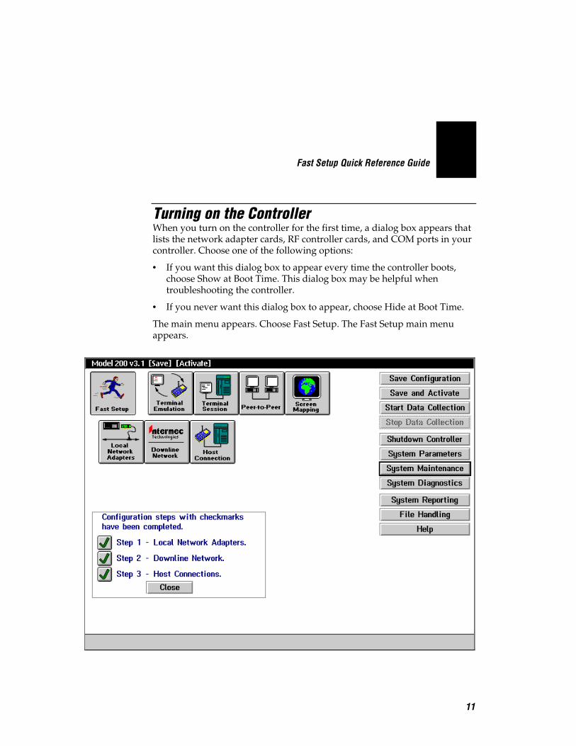
Turning on the ControllerWhen you turn on the controller for the first time, a dialog box appears thatlists the network adapter cards, RF controller cards, and COM ports in yourcontroller. Choose one of the following options:
• If you want this dialog box to appear every time the controller boots,choose Show at Boot Time. This dialog box may be helpful whentroubleshooting the controller.
• If you never want this dialog box to appear, choose Hide at Boot Time.
The main menu appears. Choose Fast Setup. The Fast Setup main menuappears.

Fast Setup Quick Reference Guide
12
About the Fast Setup Main MenuThis main menu appears whenever you turn on the Model 200 Controller. Inthe title bar, [Save] and [Activate] appear when you make changes to theconfiguration that you need to save and activate. The Fast Setup main menuhas three parts.
Toolbar ButtonsThe buttons across the top of the main menu are grouped into two sections:Fast Setup and Advanced Setup. This quick reference guide (QRG)addresses how to use the first button, Fast Setup. For more information onAdvanced Setup, see the Model 200 Controller User’s Manual.
Sidebar ButtonsThe buttons on the right side of the main menu perform system functions onthe controller. This QRG explains how to use Save Configuration, Save andActivate, Start Data Collection, Stop Data Collection, Shutdown Controller,System Parameters, and some of the commands in the System Maintenancedialog box. For more information on the other buttons, see the Model 200Controller User’s Manual.
Checklist BoxThe checklist box on the bottom left side of the main menu lists the threesteps you complete to configure the controller in Fast Setup:
1. Local Network Adapters.
This box is checked after you enter the required parameters that identifythe network adapter cards in the controller to the network.
2. Downline Network.
This box is checked after you configure the controller for your downlinedata collection network, including configuring any RF controller cards,the UDP Plus network, and any external Intermec controllers.
3. Host Connections.
This box is checked after you configure the host connections for terminalemulation, peer-to-peer applications, or terminal sessions for screenmapping.
Fast Setup Quick Reference Guide
13
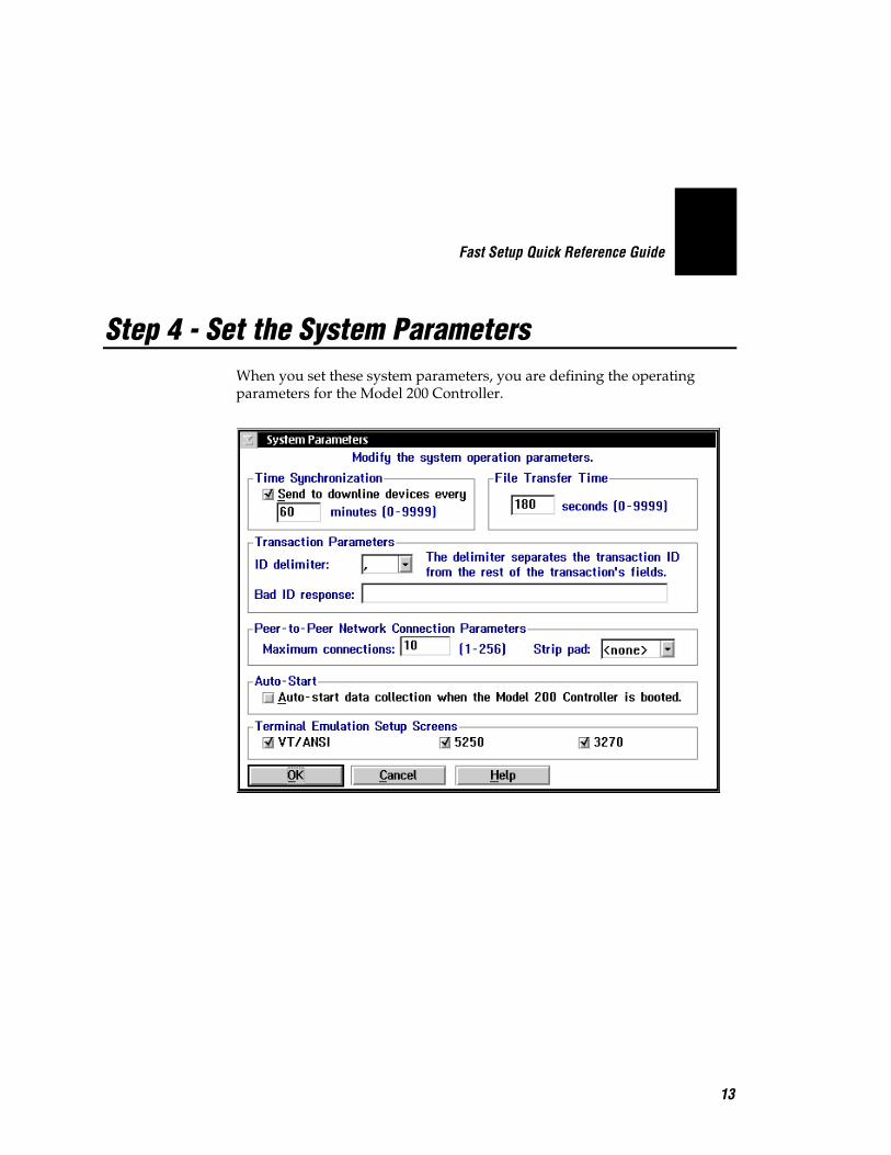
Step 4 - Set the System ParametersWhen you set these system parameters, you are defining the operatingparameters for the Model 200 Controller.

Fast Setup Quick Reference Guide
14
Field Description Value Default
Send to downlinedevices every...
This check box determines if the Model200 Controller sends its time to allexternal Intermec controllers.
Check, Clear Check
...minutes This field specifies how often inminutes the controller sends the timesynchronization message.
0 to 9999 60
File TransferTime
This box specifies how long in secondsthe controller waits for a response fromthe data collection device when it isdownloading files, before it times out.
0 to 9999 180
ID delimiter The character that the data collectiondevices use to separate the transactionID from the transaction fields.
Predefined , (comma)
Bad ID response(Optional)
The message that the controller sends tothe source of the transaction if thecontroller does not recognize thetransaction ID.
1 to 39 characters None
Max connections(Peer-to-peer)
A tuning value that defines themaximum number of connections foreach NetComm process.
1 to 256 10
Strip pad(Peer-to-peer,APPC only)
The pad character, which is used byfixed-length transactions from a hostapplication, that you want thecontroller to remove before sending thetransaction.
Predefined None
Auto-start datacollection whenthe Model 200Controller isbooted.
This check box determines if thecontroller starts data collection when itis booted.
Check, Clear Clear
TerminalEmulation SetupScreens
This box allows you to customizewhich terminal emulation buttonsappear in the main menu.
VT/ANSI, 5250,3270
All
Fast Setup Quick Reference Guide
15
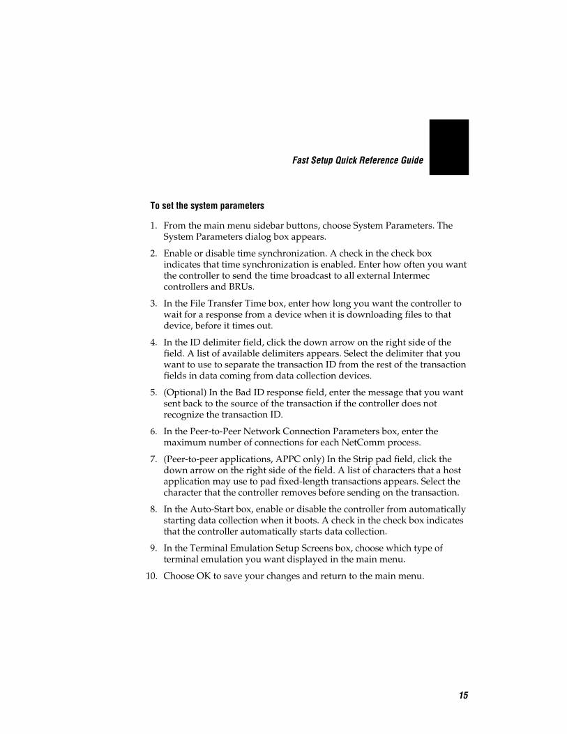
To set the system parameters
1. From the main menu sidebar buttons, choose System Parameters. TheSystem Parameters dialog box appears.
2. Enable or disable time synchronization. A check in the check boxindicates that time synchronization is enabled. Enter how often you wantthe controller to send the time broadcast to all external Intermeccontrollers and BRUs.
3. In the File Transfer Time box, enter how long you want the controller towait for a response from a device when it is downloading files to thatdevice, before it times out.
4. In the ID delimiter field, click the down arrow on the right side of thefield. A list of available delimiters appears. Select the delimiter that youwant to use to separate the transaction ID from the rest of the transactionfields in data coming from data collection devices.
5. (Optional) In the Bad ID response field, enter the message that you wantsent back to the source of the transaction if the controller does notrecognize the transaction ID.
6. In the Peer-to-Peer Network Connection Parameters box, enter themaximum number of connections for each NetComm process.
7. (Peer-to-peer applications, APPC only) In the Strip pad field, click thedown arrow on the right side of the field. A list of characters that a hostapplication may use to pad fixed-length transactions appears. Select thecharacter that the controller removes before sending on the transaction.
8. In the Auto-Start box, enable or disable the controller from automaticallystarting data collection when it boots. A check in the check box indicatesthat the controller automatically starts data collection.
9. In the Terminal Emulation Setup Screens box, choose which type ofterminal emulation you want displayed in the main menu.
10. Choose OK to save your changes and return to the main menu.
Fast Setup Quick Reference Guide
16
Step 5 - Set Up the Data Collection EnvironmentWorksheets available
• Model 200 Controller to RF Card Worksheet• Model 200 Controller to TRAKKER Antares Terminals Worksheet• Model 200 Controller to 9180 and CrossBar Worksheet• Model 200 Controller to 9180 Worksheet• Model 200 Controller to CrossBar Worksheet
You can use Fast Setup to define the parameters for any external Intermeccontrollers that exist downline from the Model 200 Controller, for RFcontroller cards that you may have inside the controller, and for thecontroller to communicate with the TRAKKER® Antares™ terminals usingUDP Plus. Fast Setup assumes that any downline device that you add to thenetwork is configured with factory defaults.
RF controller cards Fast Setup configures the controller to communicatewith the first 9181 BRU on RF Card 1 and it enables this BRU. It also sets upthis BRU to communicate with the first eight RF devices. If you have morethan one RF card or more than one BRU, you will need to configure their RFparameters. For help configuring the other RF card, see Chapter 3,“Connecting to the Intermec RF Network” in the Model 200 Controller User’sManual. For help configuring the BRU, see the 900 MHz RF Equipment User’sManual.
UDP Plus network Fast Setup configures the controller to communicate withJANUS devices and TRAKKER Antares terminals through the access pointson an Ethernet or token ring network. You also need to define IP addressesfor each of the terminals. Before you can verify your connection to the UDPPlus network, you must define an IP address for the Ethernet or token ringcard. For help, see “Ethernet Adapter Card” and “Token Ring AdapterCard” later in this quick reference guide.
External Intermec controllers Fast Setup configures a few of the parametersthat let the controller communicate with the external Intermec controller.However, you may still need to configure your external controller to sendand receive transactions to the devices. Refer to your controller’s user’smanual.
Note: Once you define your external Intermec controllers, your RF controller cards,or UDP Plus and you choose Configure, Fast Setup does not let you edit theconfiguration. You need to use Advanced Setup to change any parameters.
Fast Setup Quick Reference Guide
17
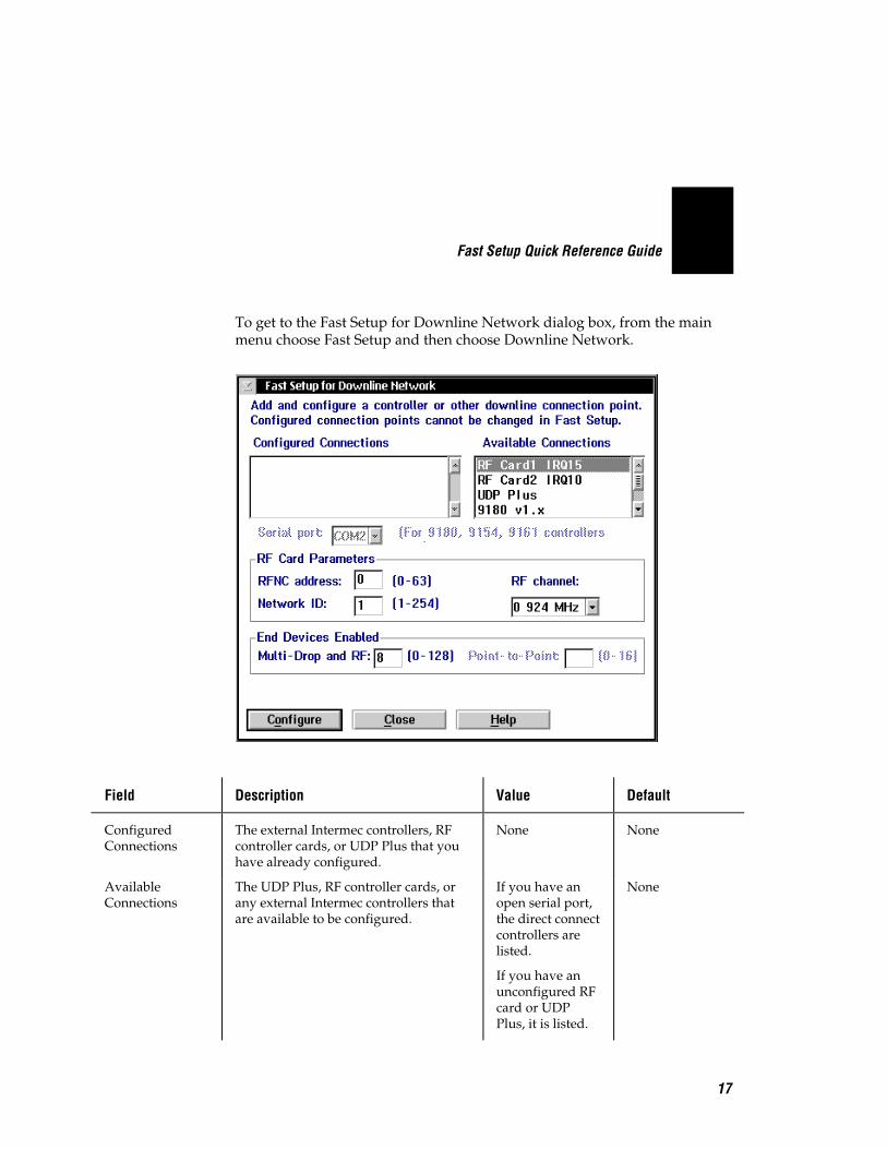
To get to the Fast Setup for Downline Network dialog box, from the mainmenu choose Fast Setup and then choose Downline Network.
Field Description Value Default
ConfiguredConnections
The external Intermec controllers, RFcontroller cards, or UDP Plus that youhave already configured.
None None
AvailableConnections
The UDP Plus, RF controller cards, orany external Intermec controllers thatare available to be configured.
If you have anopen serial port,the direct connectcontrollers arelisted.
If you have anunconfigured RFcard or UDPPlus, it is listed.
None
Fast Setup Quick Reference Guide
18
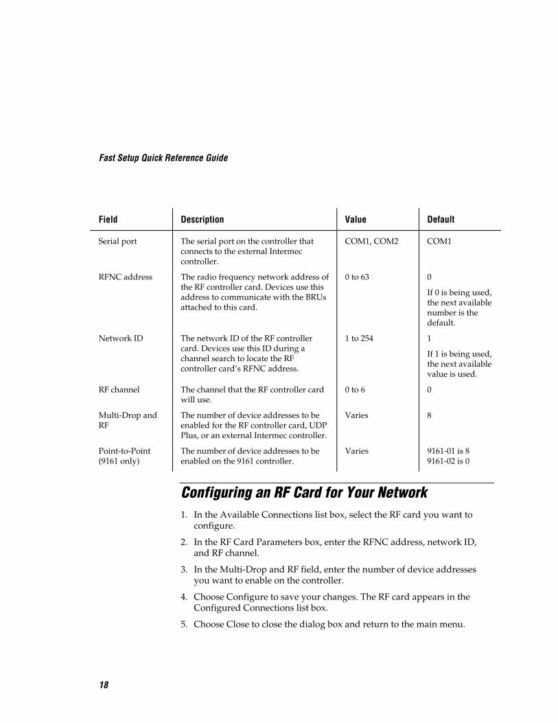
Field Description Value Default
Serial port The serial port on the controller thatconnects to the external Intermeccontroller.
COM1, COM2 COM1
RFNC address The radio frequency network address ofthe RF controller card. Devices use thisaddress to communicate with the BRUsattached to this card.
0 to 63 0
If 0 is being used,the next availablenumber is thedefault.
Network ID The network ID of the RF controllercard. Devices use this ID during achannel search to locate the RFcontroller card’s RFNC address.
1 to 254 1
If 1 is being used,the next availablevalue is used.
RF channel The channel that the RF controller cardwill use.
0 to 6 0
Multi-Drop andRF
The number of device addresses to beenabled for the RF controller card, UDPPlus, or an external Intermec controller.
Varies 8
Point-to-Point(9161 only)
The number of device addresses to beenabled on the 9161 controller.
Varies 9161-01 is 89161-02 is 0
Configuring an RF Card for Your Network1. In the Available Connections list box, select the RF card you want to
configure.
2. In the RF Card Parameters box, enter the RFNC address, network ID,and RF channel.
3. In the Multi-Drop and RF field, enter the number of device addressesyou want to enable on the controller.
4. Choose Configure to save your changes. The RF card appears in theConfigured Connections list box.
5. Choose Close to close the dialog box and return to the main menu.

Fast Setup Quick Reference Guide
19
Configuring a UDP Plus Network1. In the Available Connections list box, select UDP Plus.
2. Choose Configure to save your changes. The Setup for UDP PlusTerminals dialog box appears.
To set up the UDP Plus devices using a DNS server
1. In the Number of terminals to enable field, enter the number of logicalnames that you want the controller to generate.
2. Check the Use DNS check box.
Note: Before you can use DNS, you must use Advanced Setup to configure aDNS server in the DNS Configuration dialog box.
3. In the Base logical name field, enter the base name that the controlleruses to create a unique logical name for each terminal. The controllerappends a sequential 3-digit number to this name for each terminal.

Fast Setup Quick Reference Guide
20
4. In the Domain field, enter the name of the domain that all of theterminals are in.
Note: If you enable the Use DNS check box and you do not enter a domain, theserver searches the domains that are listed in the DNS Configuration dialog box.
5. Choose OK. The controller generates the logical names and you return tothe Fast Setup for Downline Network dialog box.
6. Choose Close to close the dialog box and return to the main menu.
To set up the UDP Plus devices using the controller to generate IP addresses
1. In the Number of terminals to enable field, enter the number of IPaddresses that you want the controller to generate.
2. Clear the Use DNS check box.
3. In the Base logical name field, enter the base name that the controlleruses to create a unique logical name for each terminal. The controllerappends a sequential 3-digit number to this name for each terminal.
4. In the Starting IP address field, enter the starting IP address. The IPaddress must be a valid IP v4 address.
5. In the Subnet mask field, enter the subnet mask that the server uses tovalidate the IP addresses. The controller verifies that they do not cross asubnet boundary.
6. Choose OK. The controller assigns valid sequential logical names and IPaddresses to the terminals starting with the starting IP address and thenyou return to the Fast Setup for Downline Network dialog box.
7. Choose Close to close the dialog box and return to the main menu.

Fast Setup Quick Reference Guide
21
Configuring an Intermec Controller for YourNetwork1. In the Available Connections list box, select the external Intermec
controller you want to configure.
2. In the Serial port field, click the down arrow on the right side of the field.A list that contains the available serial ports appears. Choose the serialport on the Model 200 Controller that is connected to the externalcontroller.
3. In the End Devices Enabled box, enter the number of Multi-Drop orPoint-to-Point device addresses you want to enable on the controller.
Protocol Controller End Devices Enabled
Multi-Drop and RF 9180 v1.x, 9180 v2.x 0 through 128
9154 0 through 32
9161-02 0 through 128
Point-to-Point 9161-01 0 through 16
9161-02 0 through 12
4. Choose Configure to save your changes. The controller appears in theConfigured Connections list box.
5. Choose Close to return to the main menu.
Verify Your Data Collection EnvironmentOnce you configure the Fast Setup for Downline Network dialog box, youmay want to verify that you have a connection between the Model 200controller and a device.
When sending a transaction to a device (destination), make sure that yourdevice is ready to accept the transaction. If your device is not ready, thetransaction is written to the Hot Standby file. If the device does not knowhow to interact with the Hot Standby file, subsequent transactions will alsobe written to the Hot Standby file. In this case, clear the Hot Standby filebefore sending another transaction to the device. For help, see “Clearing theHot Standby Files” in Appendix A in the Model 200 Controller User’s Manual.
Fast Setup Quick Reference Guide
22
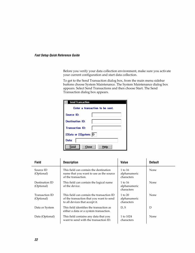
Before you verify your data collection environment, make sure you activateyour current configuration and start data collection.
To get to the Send Transaction dialog box, from the main menu sidebarbuttons choose System Maintenance. The System Maintenance dialog boxappears. Select Send Transactions and then choose Start. The SendTransaction dialog box appears.
Field Description Value Default
Source ID(Optional)
This field can contain the destinationname that you want to use as the sourceof the transaction.
1 to 16alphanumericcharacters
None
Destination ID(Optional)
This field can contain the logical nameof the device.
1 to 16alphanumericcharacters
None
Transaction ID(Optional)
This field can contain the transaction IDof the transaction that you want to sendto all devices that accept it.
1 to 20alphanumericcharacters
None
Data or System This field identifies the transaction aseither a data or a system transaction.
D, S D
Data (Optional) This field contains any data that youwant to send with the transaction ID.
1 to 1024characters
None

Fast Setup Quick Reference Guide
23
To verify your data collection environment
1. (Optional) In the Source ID field, enter a destination name that you wantto use as the source of the transaction.
2. If you want to send the transaction to one device, in the Destination IDfield enter the logical name of the device that you are using to verify theconnection.
Note: If you are using the Send Transactions feature to verify your hostconnection, enter the name of the host application.
Or, if you want to send the transaction to all the devices that areconfigured to accept it, in the Transaction ID field enter the unique nameof the transaction.
3. In the Data or System field, enter D or S. This field defines thetransaction as either a data or a system transaction.
4. (Optional) In the Data field, enter any data you want to send with thetransaction ID.
5. Choose Send to send the transaction to the device.
6. Choose Close to close the dialog box and return to the SystemMaintenance dialog box.
7. Choose Close to return to the main menu.

Fast Setup Quick Reference Guide
24
Step 6 - Set Up the Host CommunicationsEnvironment
To set up the host communications environment, you need to configure anynetwork adapter cards in your Model 200 Controller. The network adaptercards that your controller may contain are:
• Ethernet
• token ring
• coaxial
• twinaxial
• SDLC
To configure the network adapter cards
1. From the main menu, choose Fast Setup.
2. Choose Local Network Adapter.
Note: Fast Setup grays out the buttons for any network adapter cards that arenot installed in your controller.
3. Choose the button for the network adapter card you want to configureand follow the appropriate instructions in this section.

Fast Setup Quick Reference Guide
25
Ethernet Adapter CardIf you are using Ethernet adapter cards in the controller in a TCP/IPnetwork, use Fast Setup to enter the parameters required for the TCP/IPprotocol for each of the cards. Use the information from the NetworkAdapter Cards Worksheet to help you fill in the fields in this dialog box.
Note: The default setting for the Ethernet adapter card is 10BaseT. Contact yourlocal Intermec representative if you are using 10Base2 or 10Base5.
Note: If your controller contains two cards (two Ethernet cards or one Ethernet andone token ring card) that communicate using TCP/IP, each card must use adifferent subnet.
If you are not using the Ethernet adapter cards in a TCP/IP network, you donot need to configure them.

Fast Setup Quick Reference Guide
26
Field Description Value Default
Ethernet TCP/IPcard
The Ethernet card that you areconfiguring.
Ethernet 1Ethernet 2
Ethernet 1
Use DHCP This check box enables this networkadapter card to be administered by aDHCP server.
Check, Clear Clear
Local host name(Optional)
A meaningful name that identifies thecontroller to the network.
1 to 12alphanumericcharacters
ACCNET
Local IP address The IP address that identifies theEthernet card. The IP address must be avalid IP v4 address.
xxx.xxx.xxx.xxxwhere xxx is avalue between 0and 255
None
Subnet mask The mask that is used in the IP protocollayer to separate the subnet addressfrom the local IP address.
xxx.xxx.xxx.xxxwhere xxx is avalue between 0and 255
Calculated basedon IP address
To configure the Ethernet card
1. From the main menu, choose Fast Setup.
2. Choose Local Network Adapters.
3. Choose Ethernet. The Ethernet TCP/IP Adapter Configuration dialogbox appears.
4. In the Ethernet TCP/IP Card field, click the down arrow on the rightside of the field. A list of Ethernet cards that are installed in yourcontroller appears. Select the card you want to configure.
Note: If you have two or more 10 Mbps Ethernet cards, Ethernet 1 is theEthernet card that is in the slot the furthest left if you are facing the controllerfront panel. If you have a 100 Mbps Ethernet card, it is Ethernet 1.
5. To enable DHCP, check the Use DHCP check box. Go to Step 9.
Or, to disable DHCP, clear the Use DHCP check box. Go to Step 6.

Fast Setup Quick Reference Guide
27
6. (Optional) In the Local host name field, enter a meaningful TCP/IP hostname for the controller.
7. In the Local IP address field, enter the address that identifies thisEthernet card in the controller (host) to the network. This IP addressmust be a valid IP v4 address.
8. In the Subnet mask field, enter the mask used in the IP protocol layer toseparate the subnet address from the local IP address.
9. Choose OK to save your changes and return to main menu.
Token Ring Adapter CardIf you are configuring the token ring card in the controller for a TCP/IPnetwork, you need to use Advanced Setup. For help, see Chapter 5,“Connecting to an Ethernet/Token Ring Network” in the Model 200Controller User’s Manual.
If you are not using your token ring card in a TCP/IP network, you do notneed to set any parameters for a token ring adapter connection. Allparameters are set to default values. If you choose Token Ring, a messagebox appears.
Choose OK to close the message box and return to the main menu.
Coaxial Adapter CardYou do not need to set any parameters for a coaxial adapter connection. Allparameters are set to default values. If you choose Coaxial, a message boxappears.
Choose OK to close the message box and return to the main menu.
Fast Setup Quick Reference Guide
28
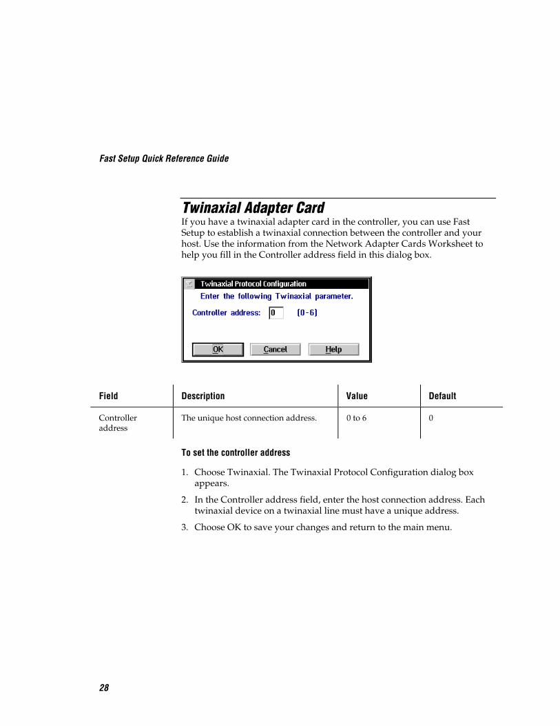
Twinaxial Adapter CardIf you have a twinaxial adapter card in the controller, you can use FastSetup to establish a twinaxial connection between the controller and yourhost. Use the information from the Network Adapter Cards Worksheet tohelp you fill in the Controller address field in this dialog box.
Field Description Value Default
Controlleraddress
The unique host connection address. 0 to 6 0
To set the controller address
1. Choose Twinaxial. The Twinaxial Protocol Configuration dialog boxappears.
2. In the Controller address field, enter the host connection address. Eachtwinaxial device on a twinaxial line must have a unique address.
3. Choose OK to save your changes and return to the main menu.
Fast Setup Quick Reference Guide
29
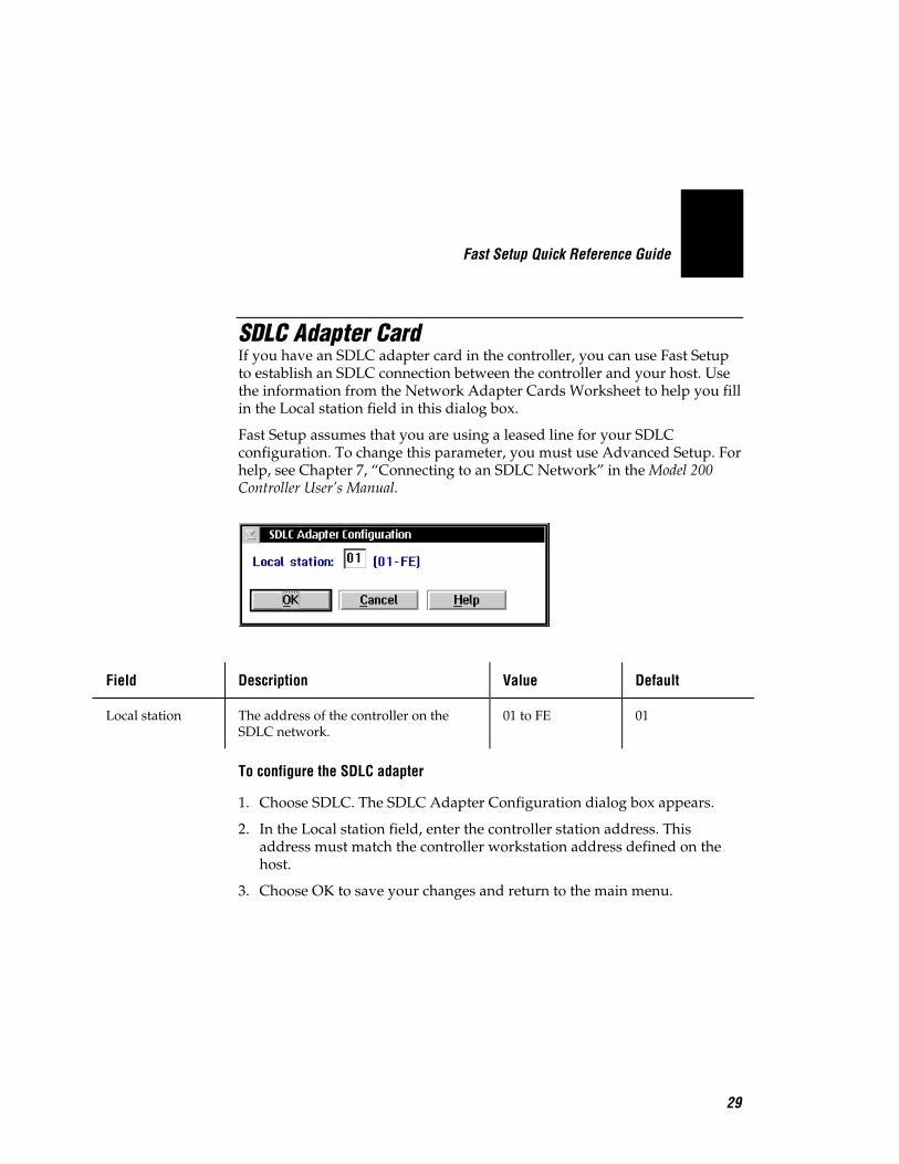
SDLC Adapter CardIf you have an SDLC adapter card in the controller, you can use Fast Setupto establish an SDLC connection between the controller and your host. Usethe information from the Network Adapter Cards Worksheet to help you fillin the Local station field in this dialog box.
Fast Setup assumes that you are using a leased line for your SDLCconfiguration. To change this parameter, you must use Advanced Setup. Forhelp, see Chapter 7, “Connecting to an SDLC Network” in the Model 200Controller User’s Manual.
Field Description Value Default
Local station The address of the controller on theSDLC network.
01 to FE 01
To configure the SDLC adapter
1. Choose SDLC. The SDLC Adapter Configuration dialog box appears.
2. In the Local station field, enter the controller station address. Thisaddress must match the controller workstation address defined on thehost.
3. Choose OK to save your changes and return to the main menu.

Fast Setup Quick Reference Guide
30
Step 7 - Configure the Host Environment ParametersYou need to define the host environment parameters that tell the Model 200Controller how to communicate with the host. Perform one of theseprocedures:
• Set up VT100/220/320, ANSI, 5250, or 3270 terminal emulation.
• Set up peer-to-peer links to run remote TCP/IP or APPC applications.
• Set up VT100/220/320, ANSI, 5250, or 3270 terminal sessions for screenmapping.
Note: Once you define your hosts and you choose OK, Fast Setup does not let youedit the configuration. You need to use Advanced Setup to change any parameters.
To configure the host environment parameters
1. From the main menu, choose Fast Setup.
2. Choose Host Connection.
3. Choose the button for the type of communications you want to configureand follow the appropriate instructions in this section.

Fast Setup Quick Reference Guide
31
Setting Up Telnet Terminal EmulationYou can use Fast Setup to set up VT100/220/320 or ANSI terminalemulation (TE) between JANUS™ devices and TRAKKER Antares terminalsand your TCP/IP hosts. You can also set up TN5250 or TN3270 TE betweenyour JANUS 2.4 GHz RF devices that are running UDP Plus and yourJANUS 900 MHz RF devices and an IBM host that supports Telnet. Youneed to identify all remote host names and their IP addresses.
You also need to decide which terminals from the Available Terminals listbox you want to explicitly link to a host. If an explicit link is set up betweena terminal and a host, it means that the terminal can only start TE sessionswith that host. If no explicit link is set up, the terminal can start a TE sessionwith any host in the Host Name list. The controller starts a TE session withthe host that is configured on the terminal.
You can link as many device addresses as you want. However, the numberof terminals that can simultaneously communicate through the controllerdepends on
• the number of devices you enabled in the Fast Setup for DownlineNetwork dialog box.
• the number of terminals in your terminal license.
Note: You may need to load the correct TE software on all of the JANUS devicesthat you will be using as terminals. This software is available on the Model 200Controller. Refer to Chapter 8, “Using Terminal Emulation” in the Model 200Controller User’s Manual.
Use the information from the Telnet Terminal Emulation Worksheet to helpyou fill in this dialog box.
Fast Setup Quick Reference Guide
32
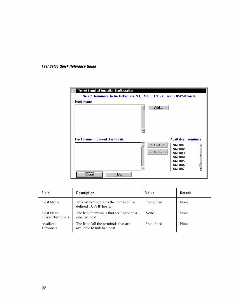
Field Description Value Default
Host Name This list box contains the names of thedefined TCP/IP hosts.
Predefined None
Host Name -Linked Terminals
The list of terminals that are linked to aselected host.
None None
AvailableTerminals
The list of all the terminals that areavailable to link to a host.
Predefined None

Fast Setup Quick Reference Guide
33
To set up Telnet terminal emulation
1. Choose Telnet Terminal Emulation. The Telnet Terminal EmulationConfiguration dialog box appears.
2. Make sure you have added all the Telnet hosts that the terminals willaccess. The Host Name list box contains all the defined host names.
To add a host, follow the instructions in “Adding a TCP/IP Host” in thenext section.
3. (Optional) Create any explicit links between hosts and terminals.
a. In the Host Name list box, select the host that you want to link to aterminal.
b. In the Available Terminals list box, select the logical name of theterminal you want to link to the host.
c. Choose Link. The host name and the logical name appear in the HostName - Linked Terminals list box.
4. (Optional) Unlink any explicit links between hosts and devices.
a. In the Host Name - Linked Terminals list box, select the terminal thatyou want to unlink from a host.
b. Choose Unlink. The host name and the logical name are removedfrom the Host Name - Linked Terminals list box.
5. Choose Close to close this dialog box and return to the main menu.
Fast Setup Quick Reference Guide
34
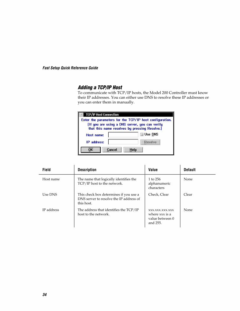
Adding a TCP/IP HostTo communicate with TCP/IP hosts, the Model 200 Controller must knowtheir IP addresses. You can either use DNS to resolve these IP addresses oryou can enter them in manually.
Field Description Value Default
Host name The name that logically identifies theTCP/IP host to the network.
1 to 256alphanumericcharacters
None
Use DNS This check box determines if you use aDNS server to resolve the IP address ofthis host.
Check, Clear Clear
IP address The address that identifies the TCP/IPhost to the network.
xxx.xxx.xxx.xxxwhere xxx is avalue between 0and 255.
None
Fast Setup Quick Reference Guide
35
To determine the host IP address using DNS
1. From the Telnet Terminal Emulation Configuration dialog box, chooseAdd. The TCP/IP Host Connection dialog box appears.
2. In the Host name field, enter the abbreviated or long host name. If youenter the abbreviated name, the controller searches the domain names inthe DNS Configuration dialog box to determine the long host name.
3. Enable the Use DNS check box.
Note: Before you enable this check box, you must first configure a DNS serverin the DNS Configuration dialog box.
4. (Optional) Choose Resolve. The controller searches in the domains thatare listed in the DNS Configuration dialog box for the host name andresolves the IP address.
5. Choose OK to save your changes and return to the Telnet TerminalEmulation Configuration dialog box.
To configure the host IP address manually
1. From the Telnet Terminal Emulation Configuration dialog box, chooseAdd. The TCP/IP Host Connection dialog box appears.
2. In the Host name field, enter the host name.
3. Make sure the Use DNS check box is disabled.
4. In the IP address field, enter the host’s IP address.
5. Choose OK to save your changes and return to the Telnet TerminalEmulation Configuration dialog box.

Fast Setup Quick Reference Guide
36
Setting Up 5250 SNA Terminal EmulationYou can use Fast Setup to set up 5250 SNA terminal emulation (TE) betweenyour JANUS 900 MHz RF devices or your TRAKKER Antares terminals andSNA hosts. You need to identify all remote host names.
You also need to decide which terminals from the Available Terminals listbox you want to explicitly link to a host. If an explicit link is set up betweena terminal and a host, it means that the terminal can start a TE session onlywith that host. If no explicit link is set up, the terminal can start a TE sessionwith any host in the Host Name list. It will start a TE session with the hostthat is configured on the terminal.
You can link as many terminals as you want. However, the number ofterminals that can simultaneously communicate through the controllerdepends on
• the number of devices you enabled in the Fast Setup for DownlineNetwork dialog box.
• the mode you are using to define the terminal session characteristicsbetween the controller and the SNA host. The default mode is #INTER.For help, see “Creating Terminal Sessions” in Chapter 10 in the Model200 Controller User’s Manual.
• the number of terminals in your terminal license.
• the maximum number of virtual devices the AS/400 5250 Display StationPass-Through program supports.
Note: Your JANUS 900 MHz RF devices and your TRAKKER Antares terminalscome with the 5250 TE software already loaded. However, this software is alsoavailable on the Model 200 Controller.
Also, you must configure your terminals to use the SNA protocol.
Use the information from the 5250 Terminal Emulation Worksheet to helpyou fill in this dialog box.

Fast Setup Quick Reference Guide
37
Field Description Value Default
Host Name This list box contains the names of thedefined SNA hosts.
Predefined None
Use devicenames
This check box determines if theselected host in the Host Name list boxuses the logical name of the deviceswhen establishing terminal sessions.
Check, Clear Clear
Host Name -Linked Terminals
The list of terminals that are linked to aselected host.
None None
AvailableTerminals
The list of all terminals that areavailable to link to a host.
Predefined None
Fast Setup Quick Reference Guide
38
To set up 5250 terminal emulation
1. Choose 5250 Terminal Emulation. The 5250 Terminal EmulationConfiguration dialog box appears.
2. Make sure you have added all the SNA hosts that the terminals willaccess for terminal emulation. The Host Name list box contains all thedefined host names.
To add a host, follow the instructions in “Adding an IBM SNA Host” inthe next section.
3. Check the Use device names check box if you want the selected host touse the logical name of the devices when establishing terminal sessions.A Yes appears next the host name under the Names column.
4. (Optional) Create any explicit links between hosts and terminals.
a. In the Host Name list box, select the host that you want to link to aterminal.
b. In the Available Terminals list box, select the terminal you want tolink to the host.
c. Choose Link. The terminal appears in the Host Name - LinkedTerminals list box.
5. (Optional) Unlink any explicit links between hosts and terminals.
a. In the Host Name - Linked Terminals list box, select the terminal youwant to unlink from a host.
b. Choose Unlink. The host name and logical name are removed fromthe Host Name - Linked Terminals list box.
6. Choose Close to close this dialog box and return to the main menu.

Fast Setup Quick Reference Guide
39
Adding an IBM SNA Host
Field Description Value Default
Host name A name that identifies this SNA host.You can use this internal name to makethe host LU name more meaningful.
1 to 8alphanumericcharacters
None
Adapter card The network adapter card you areusing to connect to the host.
Ethernet, tokenring, twinaxial,SDLC
Ethernet 1
Network ID Identifies the network ID on which thehost resides. This ID must match thenetwork ID configured on the host.
1 to 8alphanumericcharacters
Controller’snetwork ID fromthe SNA localnode definition
Host LU The LU name that identifies the host.This field must match the control point(CP) name or node name of the host.
1 to 8 alpha-numeric andspecial characters
Host name
Local PU(Ethernet ortoken ring only)
A unique PU name for the host thatallows the terminals to communicatewith more than one host using the sameupline adapter card.
8 uppercasealphanumeric orspecial characters
SNA node name+ 2-digit suffix,starting with 01
Address(Ethernet ortoken ring only)
The LAN adapter address of the host. Token ring MACaddress format
None
Fast Setup Quick Reference Guide
40
To add an IBM SNA host
1. From the 5250 Terminal Emulation Configuration dialog box, chooseAdd. The Host Connection Configuration dialog box appears.
2. In the Host name field, enter a meaningful name for the host.
3. In the Adapter card field, click the down arrow on the right side of thefield. A list that contains the available adapter cards appears. Select theadapter card you are using to connect to the host.
4. In the Network ID field, enter the network ID of the network on whichthe host resides.
5. In the Host LU field, enter the LU (logical unit) name that identifies thehost. This field must match the control point (CP) name or node name ofthe host.
6. (Ethernet or token ring only) In the Local PU field, enter a unique PU(physical unit) name for the host. The default name is the local SNAnode name plus a 2-digit suffix.
7. (Ethernet or token ring only) In the Address field, enter the LAN adapteraddress of the remote host.
8. Choose OK to save your changes and return to the 5250 TerminalEmulation Configuration dialog box.
Fast Setup Quick Reference Guide
41
Setting Up 3270 SNA Terminal EmulationYou can use Fast Setup to set up 3270 SNA terminal emulation (TE) betweenyour JANUS 900 MHz RF devices or your TRAKKER Antares terminals andSNA hosts. You need to identify all remote host names.
You also need to decide which terminals from the Available Terminals listbox you want to explicitly link to a host. If an explicit link is set up betweena terminal and a host, it means that the terminal can start a TE session onlywith that host. If no explicit link is set up, the terminal can start a TE sessionwith any host in the Host Name list, as long as the host has NAU addressesavailable. It will start a TE session with the host that is configured on theterminal.
You can link as many terminals as you want. However, the number ofterminals that can simultaneously communicate through the controllerdepends on
• the number of devices you enabled in the Fast Setup for DownlineNetwork dialog box.
• the number of terminals in your terminal license.
• the NAUs available on the remote hosts. You need to define these NAUson the controller. You can add these NAUs to an NAU pool. Then,terminals that want to communicate with a host can dynamically linkwith them. Or, you can explicitly link an NAU to a terminal and a host.
Note: Your JANUS 900 MHz RF devices and your TRAKKER Antares terminalscome with the 3270 TE software already loaded. However, this software is alsoavailable on the Model 200 Controller.
Also, you must configure your terminals to use the SNA protocol.
Use the information from the 3270 Terminal Emulation Worksheet to helpyou fill in this dialog box.

Fast Setup Quick Reference Guide
42
Field Description Value Default
Host Name This list box contains the names of thedefined SNA hosts.
Predefined None
Host Name -Linked Terminal- NAU
The list of terminals and their NAUsthat are linked to a selected host.
None None
AvailableTerminals
The list of all terminals that areavailable to link to a host.
Predefined None
Fast Setup Quick Reference Guide
43
To set up 3270 terminal emulation
1. Choose 3270 Terminal Emulation. The 3270 Terminal EmulationConfiguration dialog box appears.
2. Make sure you have added all the SNA hosts that the terminals willaccess for terminal emulation. The Host Name list box contains all thedefined host names.
To add a host, follow the instructions in “Adding an IBM SNA Host”later in this section.
3. Decide how to set up NAUs for the terminals:
• Fill the NAU pool for each of the hosts, but do not explicitly link anyterminals to hosts.
• Do not fill the NAU pool for any of the hosts. When you explicitlylink terminals to hosts, the controller generates NAUs starting at 002.
• Fill the NAU pool for each of the hosts and explicitly link someterminals with hosts, and NAUs. You cannot link the NAUs in thepool.
For help, see “Filling the NAU Pool” later in this section.
4. (Optional) Create any explicit links between hosts, terminals, and NAUs.
a. In the Host Name list box, select the host that you want to link to aterminal.
b. In the Available Terminals list box, select the terminal you want tolink to the host.
c. Choose Link. The host, terminal, and first available NAU appear inthe Host Name - Linked Terminal - NAU list box.
To change the NAU that the controller assigns to the terminal, followthe instructions in “Editing a Link” later in this section.
5. (Optional) Unlink any explicit links between hosts, terminals, and NAUs.
a. In the Host Name - Linked Terminal - NAU list box, select theterminal you want to unlink from a host.
b. Choose Unlink. The host, terminal, and NAU are removed from theHost Name - Linked Terminal - NAU list box.
6. Choose Close to close this dialog box and return to the main menu.

Fast Setup Quick Reference Guide
44
Adding an IBM SNA Host
Field Description Value Default
Host name A name that identifies this SNA host.You can use this internal name to makethe host LU name more meaningful.
1 to 8alphanumericcharacters
None
Adapter card The network adapter card you areusing to connect to the host.
Ethernet, tokenring, SDLC
Ethernet 1
Local PU(Ethernet ortoken ring only)
A unique PU name for the host thatallows the terminals to communicatewith more than one host using the sameupline adapter card.
8 uppercasealphanumeric orspecial characters
SNA node name+ 2-digit suffix,starting with 01
Address(Ethernet ortoken ring only)
The LAN adapter address of the host. Token ring MACaddress format
None
Node ID Specifies the last eight characters in thehost XID that are used for establishing aconnection with the controller.
8 hexadecimalcharacters
05D00000
Fast Setup Quick Reference Guide
45
To add an IBM SNA host
1. From the 3270 Terminal Emulation Configuration dialog box, chooseAdd. The Host Connection Configuration dialog box appears.
2. In the Host name field, enter a meaningful name for the host.
3. In the Adapter card field, click the down arrow on the right side of thefield. A list that contains the available adapters appears. Select theadapter you are using to connect to the host.
4. (Ethernet or token ring only) In the Local PU field, enter a unique PU(physical unit) name for the host. The default name is the local SNAnode name plus a 2-digit suffix.
5. (Ethernet or token ring only) In the Address field, enter the LAN adapteraddress of the remote host.
6. In the Node ID field, enter the last eight characters in the XID thatestablish a host connection. The Node ID is the same as the XID.
Note: When establishing a connection, the host or controller with the higherNode ID number is the primary workstation.
7. Choose OK to save your changes and return to the 3270 TerminalEmulation Configuration dialog box.
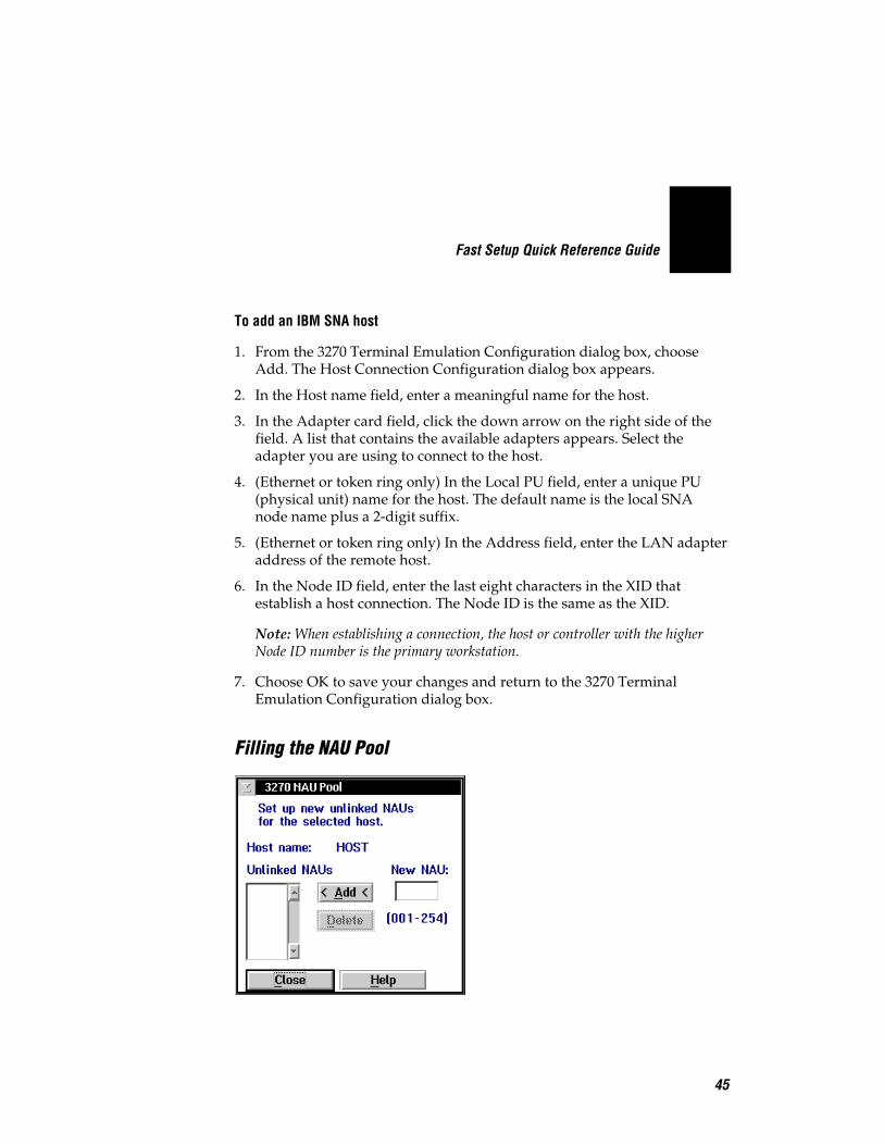
Filling the NAU Pool

Fast Setup Quick Reference Guide
46
1. From the 3270 Terminal Emulation Configuration dialog box, chooseNAU Pool. The 3270 NAU Pool dialog box appears.
2. Add all the NAUs to the NAU pool.
Note: Once an NAU is in the pool, you cannot use it in an explicit link.
a. In the New NAU field, type in the address.
b. Choose Add. The NAU is added to the Unlinked NAUs pool.
3. Remove any NAUs that you do not want in the pool or that you want touse in an explicit link.
a. In the Unlinked NAUs pool, choose the NAU to remove.
b. Choose Delete. The NAU is removed from the pool. You can now usethis NAU in an explicit link.
Editing a Link
1. From the 3270 Terminal Emulation Configuration dialog box in the HostName - Linked Terminal - NAU list box, select the NAU to change.
2. Choose Edit Link. The Edit NAU Address dialog box appears.
3. In the Current NAU field, enter a new NAU for the terminal.
4. Choose OK to save your changes and return to the 3270 TerminalEmulation Configuration dialog box.

Fast Setup Quick Reference Guide
47
Setting Up Peer-to-Peer LinksTo run TCP/IP or APPC applications in your data collection network, youmust define all the destination names in the Model 200 Controller. Thecontroller puts these names in a peer-to-peer destination list. You must alsospecify which transactions the controller routes to each application.
The Peer-to-Peer Destination Parameters dialog box also lets you set the HotStandby timeout and delivery response messages.

Fast Setup Quick Reference Guide
48
Field Description Value Default
Destination name The name of the destination(application).
1 to 16alphanumericcharacters
None
Hot Standbytimeout
The number of seconds the controllerwaits for a response from a destinationbefore it places the transactions goingto that destination in a Hot Standby file.
0 to 9999 20
Transactions heldin volatilememory
The number of transactions thecontroller keeps in RAM before itwrites them to a Hot Standby file.
None, Unlimited,Maximum
Maximum 50
International textpass-through
This check box determines how muchof the transaction is converted.
Check this box to enable this feature.The server converts only the transactionheader.
Clear this box to use limited EBCDICmapping. The server converts the entiretransaction.
Check, Clear Clear
Selected This list box contains the transactionIDs that are routed to this destination.
None None
Available This list box contains all the transactionIDs that are available to add to theSelected list box.
Predefined None
Interactiveresponse(Optional)
The message that is sent to the source ofthe transaction when the transaction forthe destination is deliveredsuccessfully.
1 to 39 characters None
Hot standby(Optional)
The message that is sent to the source ofthe transaction when the transaction forthe destination is written to a HotStandby file.
1 to 39 characters None

Fast Setup Quick Reference Guide
49
To set up your peer-to-peer link
1. Choose Peer-to-Peer. The Peer-to-Peer Destination Parameters dialog boxappears.
2. In the Destination name field, enter the name of the destination(application) that will accept the transactions in the Transaction box.
Note: You need to add the name of each data collection device in a 2.4 GHz RFnetwork that will communicate with the Model 200 Controller.
3. In the Hot Standby timeout field, enter the number of seconds thecontroller waits for an acknowledgment from the destination before itplaces the transactions going to that destination in a Hot Standby file.
4. Choose the number of transactions you want the controller to keep inRAM before it writes them to a Hot Standby file.
• Choose None if you want the transaction always written to the file.This setting is the safest setting and it is also the slowest.
• Choose Unlimited if you do not want the transaction written to thefile unless the time you set for the Hot Standby timeout expires. Thissetting is the fastest.
• Choose Maximum and enter the maximum number of transactionsthe controller stores in RAM before it writes them to a file.
5. Enable or disable international text pass-through. A check in the checkbox means that international text pass-through is enabled.
6. Add all transaction IDs that you want routed to the destination to theSelected list box.
a. From the Available list box, select a transaction to be added to theSelected list box.
b. Choose Select. The transaction ID appears in the Selected list box.
7. Remove any transactions that you do not want routed to the destinationfrom the Selected list box.
a. From the Selected list box, select a transaction to be removed.
b. Choose Remove. The transaction ID is removed from the Selected listbox.

Fast Setup Quick Reference Guide
50
8. Add any transaction IDs that are not listed in the Available list box.Follow the instructions in the next section, “Adding a Transaction.”
9. (Optional) In the Delivery Responses box, enter the messages you wantto send to the transaction source.
• In the Interactive response field, enter the message you want to sendto the source of the transaction when the transaction for thedestination is successfully delivered in Interactive mode.
• In the Hot standby field, enter the message you want to send to thesource of the transaction when the transaction for the destination isnot successfully delivered and is written to a Hot Standby file.
10. Choose OK to save your changes and return to the main menu.
Adding a TransactionYou need to define transaction IDs so the controller can route them to theirproper destination.
Fast Setup Quick Reference Guide
51
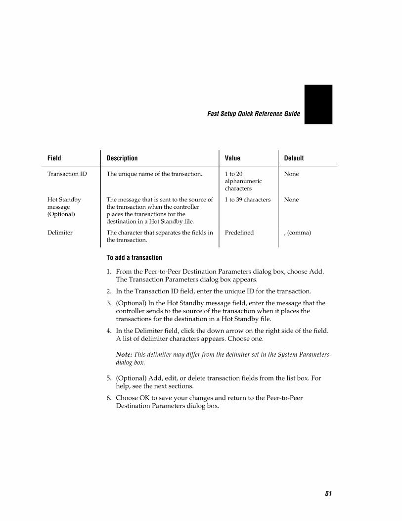
Field Description Value Default
Transaction ID The unique name of the transaction. 1 to 20alphanumericcharacters
None
Hot Standbymessage(Optional)
The message that is sent to the source ofthe transaction when the controllerplaces the transactions for thedestination in a Hot Standby file.
1 to 39 characters None
Delimiter The character that separates the fields inthe transaction.
Predefined , (comma)
To add a transaction
1. From the Peer-to-Peer Destination Parameters dialog box, choose Add.The Transaction Parameters dialog box appears.
2. In the Transaction ID field, enter the unique ID for the transaction.
3. (Optional) In the Hot Standby message field, enter the message that thecontroller sends to the source of the transaction when it places thetransactions for the destination in a Hot Standby file.
4. In the Delimiter field, click the down arrow on the right side of the field.A list of delimiter characters appears. Choose one.
Note: This delimiter may differ from the delimiter set in the System Parametersdialog box.
5. (Optional) Add, edit, or delete transaction fields from the list box. Forhelp, see the next sections.
6. Choose OK to save your changes and return to the Peer-to-PeerDestination Parameters dialog box.

Fast Setup Quick Reference Guide
52
To add transaction fields
Field Description Value Default
Field name The unique name for the transactionfield.
1 to 16alphanumericcharacters
None
Number The position of the field in thetransaction.
1 to 999 None
1. From the Transaction Parameters dialog box, choose Add. TheTransaction Field Parameters dialog box appears.
2. In the Field name field, enter a name for the transaction field.
3. In the Number field, enter the order or position of the field in thetransaction. The first field in the transaction is at position 1.
4. Choose OK to save your changes and return to the TransactionParameters dialog box.

Fast Setup Quick Reference Guide
53
Setting Up a Terminal SessionYou can use Fast Setup to establish VT, ANSI, 5250, or 3270 terminalsessions between the controller and your host. Use these sessions to accessyour host directly from the controller. By accessing your host, you canverify your host connection and you can start remote applications. Later,using Advanced Setup, you can use this session to configure and run screenmapping.
To set up a terminal session
1. Choose Terminal Session. This message box appears.
2. Choose the button for the type of terminal session you want to configureand follow the appropriate instructions for configuring this terminalsession.
Fast Setup Quick Reference Guide
54
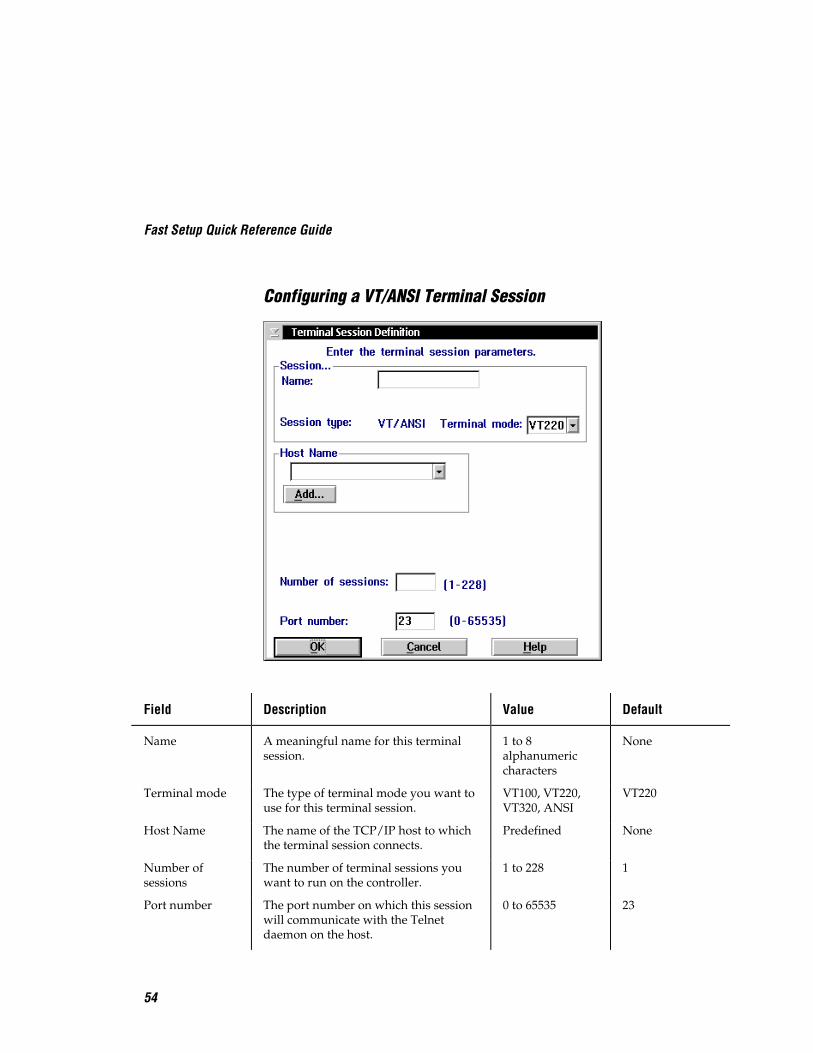
Configuring a VT/ANSI Terminal Session
Field Description Value Default
Name A meaningful name for this terminalsession.
1 to 8alphanumericcharacters
None
Terminal mode The type of terminal mode you want touse for this terminal session.
VT100, VT220,VT320, ANSI
VT220
Host Name The name of the TCP/IP host to whichthe terminal session connects.
Predefined None
Number ofsessions
The number of terminal sessions youwant to run on the controller.
1 to 228 1
Port number The port number on which this sessionwill communicate with the Telnetdaemon on the host.
0 to 65535 23

Fast Setup Quick Reference Guide
55
To configure a VT/ANSI terminal session
1. Choose VT. The Terminal Session Definition dialog box appears.
2. In the Session box, enter a meaningful name for the session.
3. In the Terminal mode field, click the down arrow on the right side of thefield. A list that contains the different terminal modes appears. Select thetype of terminal mode you want to use for this terminal session.
4. In the Host Name box, click the down arrow on the right side of thefield. A list that contains existing TCP/IP host names appears. Select thehost that you want to connect with for this session.
Or, add a new host. For help, see “Adding a TCP/IP Host” earlier in thisquick reference guide.
5. In the Number of sessions field, enter the number of terminal sessionsthat you want to run on the controller.
6. In the Port number field, enter the host port number on which thissession will communicate.
Note: Telnet uses port number 23 (default).
7. Choose OK to save your changes. A message box appears.
8. Choose Default to use the default terminal setup. The message box closesand you return to the main menu.
Or, choose Custom to customize the terminal setup. The VT Setup dialogbox appears. For help, see “Customizing the VT Terminal Setup” later inthis section.

Fast Setup Quick Reference Guide
56
Customizing the VT Terminal SetupWhen you add a new VT or ANSI terminal session and you choose Custom,the VT Setup dialog box automatically appears. If you have already createda terminal session and you want to edit the fields in this dialog box, fromthe Terminal Session list box, select the terminal session and then chooseEdit. The Terminal Session Definition dialog box appears. Choose the Editbutton that appears above the Terminal mode field. The VT Setup dialogbox appears.

Fast Setup Quick Reference Guide
57
Field Description Value Default
Cursor keys Determines whether the arrow keys onthe terminal control cursor movementor they send their application controlfunctions.
Normal,Application
Normal
Keypad Determines whether the number keyson the terminal send their keycapcharacters or they send theirprogramming functions.
Numeric,Application
Numeric
Line wrapenabled
This check box determines if textautomatically wraps to the next linewhen it reaches the right margin.
Check, Clear Clear
Controls Defines the type of control charactersthat your terminal uses.
7 bit, 8 bit 7 bit
User-DefinedKey
Determines whether or not the host canchange the user-defined keys.
Unlock, Lock Unlock
Save as newdefaults
This check box determines if the currentparameter settings are the defaultparameter settings.
Check, Clear Clear

Fast Setup Quick Reference Guide
58
To customize the terminal setup
Note: If you are defining VT100 terminals, the option buttons in the Controls boxand the User-Defined Key box are grayed out.
1. In the Terminal Keys box, choose Normal if you want to use the terminalcursor keys to move the cursor.
Choose Application if you want the cursor keys to send their applicationcontrol function.
2. In the Terminal Keys box, choose Numeric if you want the terminalnumber keys to send their numbers.
Choose Application if you want the terminal number keys to send theirprogramming functions.
3. Check or clear the text to automatically wrap to the next line when itreaches the right margin.
If line wrap is cleared, when the cursor reaches the right margin, theterminal displays each new character in the last column of the line. Eachnew character overwrites the previous character.
4. In the Controls box, choose 7-bit if you want the terminal to use all theVT320 features. This mode also supports 8-bit graphic display charactersand 7-bit control characters. Choose this setting for all VT220applications.
Choose 8-bit if you want the terminal to use all the VT320 features in an8-bit environment with 8-bit control characters. Choose this setting forVT220 applications that use 8-bit control characters.
5. In the User-Defined Key box, choose Lock if you do not want the host tochange the user-defined key definitions.
Choose Unlock if you want the host to be able to add or to change theuser-defined key definitions.
6. Check the Save as new defaults check box if you want to use the currentcustom terminal configuration as the default for all other terminals of thesame type.
7. Choose OK to save your changes and to return to the main menu.
Fast Setup Quick Reference Guide
59
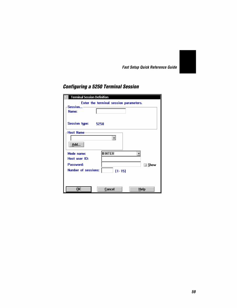
Configuring a 5250 Terminal Session

Fast Setup Quick Reference Guide
60
Field Description Value Default
Name A meaningful name for this terminalsession.
1 to 8alphanumericcharacters
None
Host Name The name of the SNA host to which theterminal session connects.
Predefined None
Mode name This name describes the class of serviceand other session characteristics thatyou may want for your network.
Predefined #INTER
Host user ID The user ID that lets you log into theremote host.
1 to 10alphanumericcharacters
None
Password The password that goes with the userID that lets you log into the remotehost.
1 to 10alphanumericcharacters
None
Show Determines if your password appearsin the field as you enter it.
Clear this check box to show asterisksfor each character you type instead ofthe actual characters.
Check, Clear Clear
Number ofsessions
The number of terminal sessions youwant to configure to this host.
15 1

Fast Setup Quick Reference Guide
61
To configure a 5250 terminal session
1. Choose 5250. The Terminal Session Definition dialog box appears.
2. In the Session box, enter a meaningful name for the session.
3. In the Host Name box, click the down arrow on the right side of thefield. A list that contains existing host names appears. Select the host thatyou want to connect with for this session. For help, see “Adding an IBMSNA Host” earlier in this document.
4. In the Mode name field, click the down arrow on the right side of thefield. A list of communication modes appears. Select the mode that youwant to use to communicate with your SNA host.
5. In the Host user ID field, enter the ID that allows you to log in to theAS/400. In the Password field, enter the password that goes with youruser ID that allows you to log into the AS/400.
Enable the Show check box to show asterisks instead of the charactersyou are typing.
Disable the Show check box to show the characters that you are typing inthe field.
6. In the Number of sessions field, enter the number of terminal sessionsyou want to run on the controller. You can enter up to 15 sessions.
7. Choose OK to save your changes and return to the main menu.

Fast Setup Quick Reference Guide
62
Configuring a 3270 Terminal Session
Field Description Value Default
Name A meaningful name for this terminalsession.
1 to 8alphanumericcharacters
None
Host Name The name of the SNA host to which theterminal session connects.
Predefined None
Number ofsessions
The number of terminal sessions youwant to configure to this host.
See table in Step4
1
NAU address The network addressable unit (NAU)that is specified for the workstation LUname.
1 to 254 None
Fast Setup Quick Reference Guide
63
To configure a 3270 terminal session
1. Choose 3270. The Terminal Session Definition dialog box appears.
2. In the Session box, enter a meaningful name for the session.
3. In the Host Name box, click the down arrow on the right side of thefield. A list that contains existing host names appears. Select the host thatyou want to connect with for this session. For help, see “Adding an IBMSNA Host” earlier in this document.
4. In the Number of sessions field, enter the number of terminal sessionsyou want to run on the controller.
Session Type Coaxial Non-Coaxial
3270 5 26
5. (non-coaxial only) In the NAU address field, enter the NAU address thatis specified for the workstation LU name.
6. Choose OK to save your changes and return to the main menu.

Fast Setup Quick Reference Guide
64
Starting a Host SessionOnce you have set up your terminal sessions on the controller, you can startthe host session from the controller.
To start a host session
1. From the main menu sidebar buttons, choose System Maintenance. TheSystem Maintenance dialog box appears.
2. In the System Maintenance list box, select Start Host Sessions and thenchoose Start. The Start Host Session dialog box appears.
3. In the Host session field, click the down arrow on the right side of thefield. A list of the terminal sessions you have configured appears. Selectone to start.
4. Choose Start. The host session starts and the host window appears.
5. Choose Close to close the dialog box and return to the SystemMaintenance dialog box.
6. Choose Close to return to the main menu.

Fast Setup Quick Reference Guide
65
Verify Your Host ConnectionOnce you configure the network adapter cards and your host connection,you may want to use the Send Transactions feature to verify that you have aconnection between the Model 200 Controller and your host. For help, see“Verifying Your Data Collection Environment” earlier in this quickreference guide.
When sending a transaction to your host application (destination), makesure that your application is ready to accept the transaction. If yourapplication is not ready, the transaction is written to the Hot Standby file. Ifthe application does not know how to interact with the Hot Standby file,subsequent transactions will also be written to the Hot Standby file. In thiscase, clear the Hot Standby file before sending another transaction to theapplication. For help, see “Viewing and Clearing the Hot Standby Files” inAppendix A in the Model 200 Controller User’s Manual.
Before you verify your host connection, make sure you activate your currentconfiguration and start data collection.

Fast Setup Quick Reference Guide
66
Step 8 - Start the ControllerBefore you start the Model 200 Controller, make sure you have performedthese tasks:
1. Connected and configured all external Intermec controllers and devices.
2. Connected the Model 200 Controller to the host and the data collectionnetwork.
3. Used Fast Setup to configure the data collection environment.
4. Used Fast Setup to configure the host communications environment.
5. Used Fast Setup to configure terminal emulation, peer-to-peerapplications, or terminal sessions.
To start the controller
1. From the main menu sidebar buttons, choose Save and ActivateConfiguration. A message box appears confirming that you want to saveyour changes and activate the configuration.
2. Choose Activate. You may be asked to shutdown the controller andpress Ctrl-Alt-Del to boot it. If not, a message box appears informingyou when your activate is successful.
Fast Setup Quick Reference Guide
67
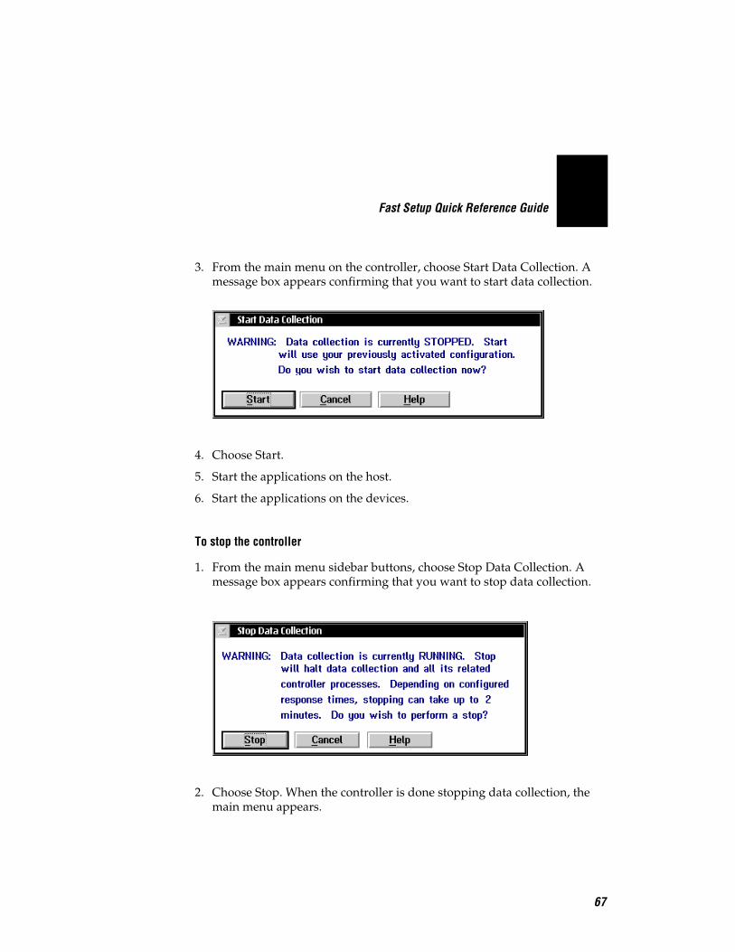
3. From the main menu on the controller, choose Start Data Collection. Amessage box appears confirming that you want to start data collection.
4. Choose Start.
5. Start the applications on the host.
6. Start the applications on the devices.
To stop the controller
1. From the main menu sidebar buttons, choose Stop Data Collection. Amessage box appears confirming that you want to stop data collection.
2. Choose Stop. When the controller is done stopping data collection, themain menu appears.

Fast Setup Quick Reference Guide
68
Where Do You Go From Here?Now that your controller is installed in your network, you can performterminal emulation or send transactions from your Intermec data collectiondevices to your host. If you need to perform Advanced Setup to edit ordelete some of the parameters, or if you need to configure screen mapping,see the Model 200 Controller User’s Manual.