faculty of manufacturing engineeringeprints.utem.edu.my/14708/1/comparative study for material...
TRANSCRIPT
UNIVERSITI TEKNIKAL MALAYSIA MELAKA
Faculty of Manufacturing Engineering
COMPARATIVE STUDY FOR MATERIAL REMOVAL RATE, SURFACE
FINISH AND ELECTRODE WEAR RA TE ON DIE SINKING EDM
Hamdi Hussein El Grour
MASTER OF ENGINEERING IN MANUFACTURING INDUSTRIAL ENGINEERING
2013
© Universiti Teknikal Malaysia Melaka
COMPARATIVE STUDY FOR MATERIAL REMOVAL RA TE, SURFACE FINISH
AND ELECTRODE WEAR RA TE ON DIE SINKING EDM
HAMDI HUSSEIN EL GROUR
A thesis submitted in fulfillment of the requirements for the degree of Master of
Engineering in Manufacturing Industrial Engineering
Faculty of Manufacturing Engineering
UNIVERSITI TEKNIKAL MALAYSIA MELA KA
2013
© Universiti Teknikal Malaysia Melaka
DECLARATION
I hereby declare that the work in this project is my own except for quotations and summat;es
which have been duly acknowledged.
rune
: ------~------:-_\.~-~·~---\\~~- ~ "\
Signature
Date :-~-b~_\_~~~------
© Universiti Teknikal Malaysia Melaka
APPROVAL
I hereby declare that I have read this dissertation/report and in my opinion this
dissertation/report is sufficient in term of scope and quality as a partial fulfillment of Master of
Manufacturing Engineering (Industrial Engineering)
Signature
Supervisor Name
Date
~---
DR. SHAJAHAN BIN MAIDIN Senior Lecturer
Faculty of Manufacturing Engineering Universiti Teknikal Malaysia Melaka
© Universiti Teknikal Malaysia Melaka
DEDICATION
Special thanks I dedicate to all people that help me in completing my final year project
espec ially to my supervisor, Dr. Shajahan Bin Maidin, my beloved family and my wife for
supporting me.
© Universiti Teknikal Malaysia Melaka

ABSTRACT
The electrical discharge machining (EDM) is one of non conventional machining process where the erosion of the work piece take place based on the the1mal energy between the electrode and the work piece. Two different work piece materials were machined using die sinking EDM to study the characteristics of each material using copper electrode. Two different work piece materials were used, aluminum and copper and the dimension for each is 100 mm length, 50mm width and 6mm thick. The Sodick CNC EDM die sink will be used as the main equipment in this project. To get the best result, the selections of parameters play a main role in producing good surface finish quality, high removal rate (MRR) and less electrode wear ratio (EWR). High electtode wear ratio (EWR) and the lower material removal rate is some of the problems in EDM machine that will decrease machining productivity. There are four different pulse cunent that will be tested (8 , 12, 16 and 20 ampere) with four pulse on time in micro second (50, 100, 150, and 200) and the reference voltage and pulse on time are kept constant 22 Volt. There are sixteen engrave will be formed in each sample. Dielectric fluid is used is kerosene and the polarity or machining type is positive. At the end of this study the optimal performance parameters will be defined and determining which mate1ial gives highest mate1ial removal rate, less surface finish as well as the conditions that give less tool wear rate (TWR). The result obtained indicating that the material removal rate MRR and TWR are increased with the increase of cun-ent. This is because the higher cun-ent means higher and stronger spark that generates or melt more material from the work piece. The result shows that pulse duration has a little effect on the MRR. But regarding the tool wear ration TWR the results show a decrease of the TWR along with the increase of pulse duration this is because of the presence of carbon layer that precipitated on the surface of the electrode and the thickness of this layer increased with the increase of pulse duration and in tum decrease the TWR. Regarding the comparative study, the result showed that aluminum has higher MRR compared with copper, this is due to the fact that aluminum has lower melting point compared with copper. And regarding the TWR, the results showed that the copper has little amount of tool wear when machined using copper electrode, this is because the copper has higher thennal conductivity compared to aluminum who has higher TWR when machined using same copper electrode. The higher the1mal conductivity means more the1mal energy this work piece can can-y and also means more facilitating the the1mal energy will be diffused which maintain the tool wear.
© Universiti Teknikal Malaysia Melaka

ABSTRAK
Menunaikan Elektrik Pemesinan adalah salah satu proses pemesinan bukan konvensional di mana satu bentuk hakisan dilakukan pada bahan kerja mengunakan tenaga haba di antara elektrod dan bahan ke1ja. bagi kajian ini CNC EDM Die Sinking dengan tembaga sebagai elektrod penghakis dipilih sebagai alat pemesinan. Di dalam kajian ini juga dua bahan kerja yang belainan tel ah dipilih iaitu aluminium dan tembaga dengan ukuran lebar 50mm, 1 OOmm panjang dan 6mm tebal diguankan. Di mana perbezaan ciri-ciri kedua-dua bahan ke1ja yang digunakan akan dikaji. Untuk mendapatkan hasil ke1ja yang terbaik terhadap bahan ke1ja Pemilihan parameter memainkan peranan utama. di mana parameter ini akan menentukan kualiti,kekemasan pe1muakaan hakisan pada bahan ke1ja, kadar hakisan yang tinggi semasa proses hakiasan (Material Remover Rate MRR) dan pengurangan kadar nisbah haus pada elektrod semasa proses penghakisan (Tool Wear Rate TWR). Terdapat empat berbeza semasa nadi(Pulse) yang akan diuji (8, 12, 16 dan 20 ampere) dengan empat nadi(Pulse) pada masa di kedua mikro ( 50, I 00 , 150, 200 dan) dan voltan rujukan dan nadi pada masa dikekalkan malar 22 Volt. Terdapat enam belas ukiran akan diadakan di setiap sampel. Cecair dielektrik digunakan adalah minyak tanah dan kekutuban atau jenis pemesinan adalah positif. Pada akhir kajian ini parameter prestasi yang optimum akan diberi untuk menentukan bahan kerja yang mana memberikan kadar penghakisan (MRR) yang tigggi,nisbah haus pada elektrod(TWR) yang rendah terhadap kemasan pe1mukaan bahan ke1ja. Keputusan yang diperolehi menunjukkan bahawa MRR kadar penghakisan bahan kerja dan TWR adalah meningkat dengan peningkatan arus elektrik. lni kerana apabila arus eleterik meningkat bermakna kekuatan percikan api (Spark) juga meningkat bagi menjana atau mencairkan lebih bahan ke1ja. Hasilnya menunjukkan bahawa masa denyutan (Pulse) mempunyai sedikit kesan kepada MRR. Tetapi bagi TWR menunjukkan penurunan daripada TWR bersama-sama dengan peningkatan masa denyutan (Pulse) ini adalah kerana kehadiran lapisan karbon yang dicetuskan pada permukaan elektrod dan ketebalan lapisan ini meningkat dengan peningkatan nadi(Pulse) tempoh dan seterusnya mengurangkan TWR itu. Bagi kajian perbandingan, kajian menunjukkan bahawa aluminium mempunyai MRR yang lebih tinggi berbanding dengan tembaga, ini adalah disebabkan oleh aluminium mempunyai takat Jebur yang lebih rendah berbanding dengan tembaga. Dan mengenai TWR, keputusan menunjukkan bahawa tembaga mempunyai jumlah TWR yang sedikit. ini adalah kerana tembaga mempunyai kekonduksian yang lebih tinggi berbanding dengan terma aluminium yang mempunyai TWR lebih tinggi semasa proses pemesinan menggunakan elektrod kuprum. Kekonduksian te1ma yang lebih tinggi be1makna lebih banyak tenaga haba bahan ke1ja ini boleh membawa dan juga be1makna lebih banyak memudahkan tenaga haba akan diserap yang mengekalkan memakai alat.
ii
© Universiti Teknikal Malaysia Melaka

ACKNOWLEDGEMENTS
I would like to express my sincere gratitude to all those who have contributed in completing
this project especially to my supe1visor Dr. Shajahan Bin Maidin for his advice and
encouragement. My appreciation is also extended to the technician Mr. Mohammad for his
assistance during conducting the experiment and for valuable feedback. Special thanks to my
research co lleagues for their encouragement and valuable discussions. I would like to thank
my wife Amna Omarfor her encouragement to carry out this research. Finally, my
appreciation goes to UniversitiTeknikal Malaysia Melaka (UTeM) for providing the facilities
and equipment to accomplish the project.
© Universiti Tekni~I Malaysia Melaka
TABLE OF CONTENT
DECLARATION
DEDICATION
ABSTRACT
AB STRAK
ACKNOWLEDGEMENT
TABLE OF CONTENT
LIST OF TABLES
LIST OF FIGURES
CHAPTER 1:
1.0
I. I
1.2
1.3
1.4
1.5
CHAPTER2:
2.1
2.2
2.3
2.4
2.5
INTRODUCTION
Overview
Project Background
Aims
Objectives
Scope
Summary
LITERATURE REVIEW
Introduction
Literature Review
History of Electrical Discharge Machining
Elect1ic Discharge Machining (EDM)
Types of Electric Discharge Machining (EDM)
2.5 . 1 Die Sinking EDM
iv
© Universiti Teknikal Malaysia Melaka
II
III
rv VII
VIII
1
2
2
3
3
4
4
4
4
5
6
6

2.5.2 Wire Cutting EDM 6
2.5.3 Electrical Discharge Grinding 6
2.5.4 Ultrasonic EDM 7
2.6 Electrical Discharge Machining processes 8
2.7 Advantages of EDM machine 10
2.8 Limitations of EDM machine 11
2,9 Machining electrically conductive materials 12
2.10 Machining Non electrically conductive mate1ials 16
2.11 Powder mixed EDM (PMEDM) 18
2.12 Effect of electrode polarity in EDM 21
2.13 Summary 22
CHAPTER:3 MACHINING PROCESSES AND EXPERIMENT SET UP 24
3.0 Overview 24
3 .1 ED M Process Parameters 24
3.2
3.3
3.4
3.5
3.6
3.7
CHAPTER4:
4.0
4.1
4.2
4.3
3.1.1 Electrical Parameters
3 .1.2 Non Electrical Parameters
Mate1ial Selection
3.2.1 Aluminum
3.2.2 Copper
Materials and Equipment
Experiment Procedure
Data collection
Analyzed method
Summary
RESULT & DISCUSSION
Overview
Data Collection
Analysis of Material Removal Rate (MRR)
Analysis of Surface Finish (Rs)
v
© Universiti Teknikal Malaysia Melaka
24
26
27
29
29
30
31
34
34
35
36
36
36
38
42

4.4
4.5
Analysis of Tool Wear Ratio (TWR)
Final Results
CHAPTER 5: CONCLUSION
REFERENCES
vi
© Universiti Teknikal Malaysia Melaka
44
52
58
60
LIST OF TABLES
3.1 Properties of Aluminum and Copper 29
3.2 Chemical Components of Aluminum and Copper 30
3.3 The experiment Parameters 32
3.4 The parameters combinations using Minitab Software 33
4.1 Data Collection and Results for Aluminum 36
4.2 Data Collection and Results for Copper 37
4.3 Averages MRR for Al and Cu at different Durations 53
4.4 Averages MRR for Al and Cu at different Pulse Currents 53
4.5 Averages TWR for Al and Cu at different CutTents 55
4.6 Averages TWR for Al and Cu at different Pulse Durations 56
vii
© Universiti Teknikal Malaysia Melaka
2. lb
2. l c
2.2
2.3
2.4
2.5
2.6
2.7
2.8
2.9
2. 10
2. 11
2. 12
2. 13
2. 14
2. 15
2.16
2. 17
3.1
3.2
3.3
3.4
3.5
LIST OF FIGURES
Inner Cavity
Spiral Cavity
The Processes of EDM
EDM machining Processes
The Effect of Pulse on Time on MRR and Rs
A comparison ofMRR using Electrode of Copper and Aluminum
MRR and wire feed
MRR and wire tension
Pulse on time duration VS MRR at I 0.93 A
Pulse on time duration VS MRR at 17.18 A
EDM for insulating materials using assisting electrode
Effect of applied voltage on MRR for 0.2 mm brass wire diameter
Effect of applied voltage on Rs for 0.25 mm brass wire diameter
Effect of powder concentration on surface roughness
MRR vs. powder concentration
TWR vs. grain size
MRR vs. pulse duration at different cun-ent with direct and reverse
polarity
TWR vs. pulse duration at different cuJTent with direct and reverse
polarity
Pulse wave from pulse generator
Flushing technique
Work piece materials
Copper electrode
EDM machine
viii
© Universiti Teknikal Malaysia Melaka
8
8
9
JO
12
13
14
14
15
15
16
17
18
19
19
20
21
22
25
27
28
28
30
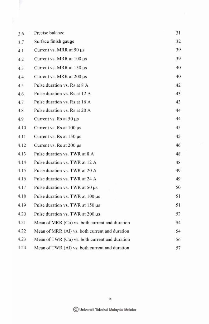
3.6 Precise balance 31
3.7 Surface finish gauge 32
4. 1 CuITent vs. MRR at 50 µs 39
4.2 CutTent vs. MRR at 100 µs 39
4.3 Cunent vs. MRR at 150 µs 40
4.4 CutTen t vs. MRR at 2 00 µs 40
4.5 Pulse duration vs. Rs at 8 A 42
4.6 Pulse duration vs. Rs at 12 A 43
4.7 Pulse duration vs. Rs at 16 A 43
4.8 Pulse duration vs. Rs at 20 A 44
4.9 Cunent vs. Rs at 50 µs 44
4.10 CuITent vs. Rs at I 00 µs 45
4. 11 Cunent vs. Rs at 150 µs 45
4.12 Cun-ent vs. Rs at 200 µs 46
4.13 Pulse duration vs. TWR at 8 A 48
4.14 Pulse duration vs. TWR at 12 A 48
4. 15 Pulse duration vs. TWR at 20 A 49
4. 16 Pulse duration vs. TWR at 24 A 49
4. 17 Pulse duration vs. TWR at 50 µs 50
4. 18 Pulse duration vs. TWR at I 00 µs 51
4. 19 Pulse duration vs. TWR at 150 µs 51
4.20 Pulse duration vs. TWR at 200 µs 52
4.21 Mean of MRR (Cu) vs. both current and dw-ation 54
4.22 Mean of MRR (Al) v . both current and duration 54
4.23 Mean of TWR (Cu) vs. both cmTent and duration 56
4.24 Mean of TWR (Al) vs. both cmTent and duration 57
ix
© Universiti Teknikal Malaysia Melaka
CHAPTER 1
INTRODUCTION
t .0 Oven'iew
This chapter briefly explains the project background .. its aim, and objective as well as
!he scope. Finally, the summary of lhe project is also provided.
1.1 Project background
Many applications nowadays such as aerospace, transportations and medical pans
caimot (and in some cases impossible) to be machined using !raditional machining
processessuch as drilling, milling and casling. Theseapplications require close tolerance, high
precision and good surface quality Pandy and Singh (20 l 0).
There are many machining process that are listed as advance machining processes such as
water jel machining, abrasive water jet machining, laser beam machining, electron beam
machining and electrical discharge machining (EDM) \1oarret7.adeh and Branch
(2012).Suitable advance machine is used according to the conditions and the type of energy to
be used to machine and create the desired pans Aghdeab and Abulwahab (20 11 ). , ,
There are n,·o main types of EDM machines, wire cutting EDM and die sinking EDM . The
v; orki ng p1inciple of these machines is based on the thermal energy !hat occurs by !he spark in
the gap between the electrode and the \vork piece where the electrode is connected to the
negative terminal whereas the work piece connected to the positive one so that more material
remova l rate can be achieved Choudh et al.(2010).The main different between those two types
are the electrode in wire ED.tvl is small diameter wire (0.25 mm) and it performance cutting
1
© Universiti Teknikal Malaysia Melaka
through while the die sinking EDM , the tool takes many shapes so that it has the same desired
shape on the work piece.
Steel and any other advanced material such as ceramic and composite are extremely difficult
ro be machined using traditional machines as their properties are not suitable, for instance l11e
high hardness and high temperature resistance and stability materials are more easily and
economy if they machined by one of non-conventional machines Pradhan et al.(2009).
This project is a comparative study where two samples (I 00x50x7 mm) of aluminum and
copper were machined using die sinking EDM. These two materials were machined using
copper electrode. These two different materials have wide use in the industry and applications
such as cars, houses, and electronic etc. These two materials are suitable for the EDM machine
to be tested as they are electrically conductive and ranged from hardness materials to less
hardness. In each sample sixteen engraves form will be machined. The discharge current are as
followed (8 ,12,16,20 and 24 Amp) and for each of discharge current, the current on time will
be applied as follov ... ·ed (50, I 00.150 and 200 micro seconds) and other factors will be constant
to know the behavior or the characterize of material in tem1 of Material Removal Rate (grn.
/min) and Surface Finish (R.) and tool wear ratio (TWR) for each material. MRR and TWR
\viii be measured using f'ommla while the surface finish is measured using surface finish
tester.
t.2 Aims
The aim 9f this project is to undertake a comparative study in tem1 <?f the characteristics
of machining two different materials (aluminumand copper) using Copper electrode by EDM
and to find the optimum process parameter for each material
1.3 Objectives
The objectives of this project are to study:
2
© Universiti Teknikal Malaysia Melaka

I . To investigate the effect of the parameterssuch as pulse one time and pulse currenron the
l\faterial Removal Rate (MRR), Surface Finish (R~) and the Tool Wear Rate (TWR).
2. To detem1ine the optimal parameters that result in high MRR and lo~>v-er tools wear ratio .
3. To conduct a comparative sn1dy between copper and aluminwn using copper electrode
EDM.
t.4 Scope
This project is limited to machining parameters on elecrrical discharge machining like
pulse on time, pulse off time and discharge voltage. The scope should be limited in this project
due to low cost and time . The project intends to i1westigate non iron content materials such as
borosi licate, composite etc. The import.ant factors such as discharge current. voltage, pulse on
time and pulse off time \viii be monitored and recorded to know how these factors effect on
the MRR and surface finish of each work piece material. The project will investigate how
these parameters affect the MRR and the surface finish (R,) of each work piece material.
However, due to the limited capability of the EDl'vl machine at the lab which does not enable
machining of non iron content, the project ,,..·ill study and utilize aluminum and copper. Beside
tha t there is only a copper tool that is used as electrode in the workshop. This is also including
calc ulation of the machining characteristics like material removal rate . Beside that this project
is go ing lo be conducted to gain deep understandi11g and knowledge about the elecllical
discharge machining.
1.5 Summary
This chapter has discussed briefly the aims and objectives , the scope of the project. This
chapter is as a fundamental for the project and act as a guidelines for the project. Generally,
this project cons ists of five chapters. Chapter t\VO will describe EDM in detail and the literature
review of the testson the ED 1 machine and how it ,.,,.orks. Chapter three is about Introduction
to 1achining Processes & Experimental. Chapter four is the Methodology which explains Lhe
approaches and methods used in perfonning the project. Chapter 5 consists of the results and
conclus ion.
3
© Universiti Teknikal Malaysia Melaka

CHAPTER 2
LITER.<\ TURE REVIE\V
2.1 Introduction
Literature review was done LO have broad idea of what other researchers have done in
this field . The literature review is used as a guide to do the analysis and gives more
info1mation about the EDM and the idea to perform the test.Literatme reviewwas done by
reading many articles, books and journal papers. Furthennore, articles and internet websites is
used as main source to get the infom1ation needed to guide and lo carry out the experiment
The history and the type of EDM machine, the limitation of the EDM machine and as well as
the process and the working principle are explained in this chapter.
2.2 Literature Review
Many research have be.en conducted using EDM machine and for each experiment or
research the input parameters are difTerenl , for instance the pulse on lime, pulse ofT time,
voltage and the currem that are used to machine electrically conductive material are different
from those which are used to machine non electrically conductive material. Due to the work
piece m~terial has to be conductive, the current used and the other parameters are high . The
literature review section will be di,·ided into two main sub contents based on the type of the
work piece material in Lenn oflhe capability of elect1ic conductivity.
2.3 History of Electrical Discharge '.\fachine (ED"'.\'0
The EDM story starled in 1943 and during the Second World War where the Soviet
government had problem in maintenance of automobile engine the problem caused by the
spark betv.1een the tungsten electrical comacts. There was l\vo sciemists Boris and Natalya
4
© Universiti Teknikal Malaysia Melaka

Lazarenko who asked by the government to investigate the problem . When they started the
investigation and fix the problem they noted that the spark become more unifonn and
predictable compared with if they are in the air. That rime they had the idea for using the spark
for erosion purpose Lazarenko B.R (1943 ). After that, Lazarenkos develop the erosion by
using unifonn spark then the process of erosion more undersn1died and start machining hard
material such as tungsten or tungsten in l 950 'sGenner, L.H and Hawonh, F.E. ( 1949).
Among drnt time the first EDM machine has been made. However, because of the bad quality
of the electrode used the machine had some limitations. After 1960 where the advanced
material had been discovered and development such as the semiconductor. quick
enhancements embarked on the EDrvt machine. Then the die sinking EDM was widely used
and the need to perfonn new machining such as cutting through which could not be performed
by die sinking EDM machine as investigated . This lead to the development of the machine
with same working principle instead the electrode \:\>'US wire. The '"''ire curting EDM during that
time was in the beginning. ln 1980 's development in the generator design and servo comrol
take place Sato er al. ( 1985). After that and in the I 990 ' s new method for the EDM machine is
developed and the using of this machine strongly increased.
2.4 Electrical Discharge Machine (EDM)
Electrical discharge machine (EDM) is an advanced machine that can perform drilling,
grinding or milling. Nowadays modem industries and applications required high precision and
high tolerance such as aerospace. transportations, elector compone_nt and medical parts. Such
requirements cannot be done using traditional machining where high force is used and cannot
machine small parts or complex shapes Anand Pandey(20 l O).l'vtany advanced machine can be
used for these special requirement such as water jet machining, electron beam machining,
laser beam machining. electrochemical machine and the electrical discharge machine.Alsothe
appearance of advanced material which is too hardleads of using or such machine.
5
© Universiti Teknikal Malaysia Melaka

2.5 Types of Electrical Discharge Machine (EDM)
2.5.1 Die Sinking EDM
This project is conducted using die sinking EDM, v.:here both Lhe tool and the
work piece as immersed in the dielectric fluid . AL the end of machining , the work piece
will take the same shape of the electrode shape (this componenl and the working
processes will be discussed in this chapter). The erosion take place by the sparks where
these sparks usually strike one at one time because the mechanism of erosion by spark
occur in different places or zones so that the nearest high zones eroded first and so
on.The different locations in the inter-electrode space have the identical local electrical
characteristics which would enable a spark to occur together in all such locations.
These sparks happen in huge numbers a! random locations between the electrode and
the work piece. As the base metal is eroded , and the spark gap subsequently increased ,
the electrode is lowered automatically by the machine so that the process can continue
uninterrupted . Several hundred thousand sparks occur per second, with the actual duty
cycle carefully controlled by the setup parameters .
2.5.2 Wire Cutting EDM
Small diameter vvire is used as electrode in this machine and the main differenl
between this machine and EDTV1 is that the wire EDM is used when the cutting through
is required also the shape of electrode in wire EDrvl is specified by small diameter wire
bu! in die sinking EDM the electrode may take circular, square, or rectangular.
2.5.3 Electrical Discharge Grinding
The grinding rotales relati ve to the rotating work piece (no abrasive involved).
6
© Universiti Teknikal Malaysia Melaka

2.5.4 Ultrasonic EDM
Ultrasonic EDM is used when high production rare is required.This machine is
mainly used to machine difficult to machine materials and high strength temperature
res.istant alloys. Ultrasonic EDM can be used to machine complex geometries in small
batches also the \vork piece has to be electrically conductive where it is one of the
limitations of this machine. The limitation will be discussed later in this chapter.
Ultrasonic EDM is used for producing dies for forging extrusion, die casting and
injection molding. Ultrasonic EDM can be used to machine extremely hard material
and complex geometries where il is impossible to be machined using traditional
machines. Also ultrasonic EDM can be used to make stepped cavities Figure2. la
where square electrode is used and the work piece is moving in x-y in horizontal
direction. Also inner cavity can be perfonned where the electrode is designed with
hanged tip wfoch slowly opened and rotated inside the \.VOrk piece to produce the
cavit); Figure2.1 b. Spiral cavity also can be machined by using slowly rotating
electrode Figure2. I c.
Figme2. I a: Stepped cavities counesy of AGIE Ltd.
7
© Universiti Teknikal Malaysia Melaka

Figure2. lb: Inner cavities Luziesa France
~Electrode Figure2.lc: Spiral cavity American Machinist
2.6 Electrical Discharge Machining Processes
The erosion of the work piece is taking place due to thennal energy generated by EDM
macb~e . Both electrode and \vork piece are immersed in diele~tric fluid (ionized water or
kerosene usually used). When the high voltage is applied (300 V) in modulated pulses this
cause the free electrons of the tool be subjected to high force \vhich in turn emitting the
electrons. These electrons then accelerated toward the work piece via the dielectric fluid. As
they are moving quickly from tool to work piece collision with dielectric molecules takes
place. Because of this reaction between the free electrons and the molecules more positive
ions and electrons will be generated due to the collision. These actions reoccurring again and
again till the plasma channel where the temperature approximately 8000 to I 0,000°C and
because of the very 10\v electrical conductivity that the plasma bas, this makes the electrons
8
© Universiti Teknikal Malaysia Melaka
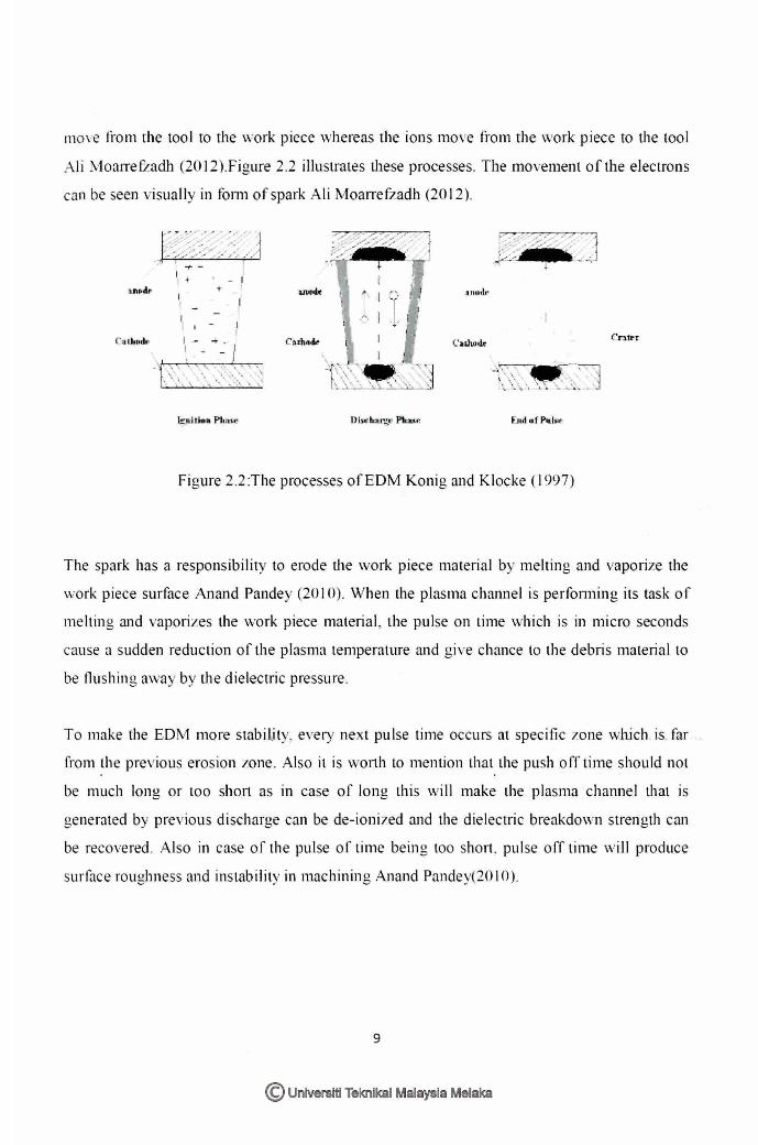
move from rhe tool to the work piece whereas the ioos move from the work piece to the tool
Ali Moarrefradh (2012).Figure 2.2 illustrates these processes. The movement of the electrons
can be seen visually in fonn of spark Ali MoarrefZadh (2012).
a.ruiodt
I - -+ . I - - I
l;Jt1 11e11 Pio:•<~
Figure 2.2 :The processes of EDM Konig and Klocke ( 1997)
The spark has a responsibility to erode the work piece material by melting and vaporize the
'.vork piece surface Anand Pandey (20 I 0). When the plasma channel is perfonning its task of
melting and vaporizes the work piece material , the pulse on time which is in micro seconds
cause a sudden reduction of the plasma temperature and give chance to the debris material to
be flushing av.·ay by the dielectric pressure.
To make the ED ti more stabiLity, every next pulse time occurs at spec ific zone \Vhich is. far
from the previous erosion 1:one. Also it is wo11h to mention that the push off time should not . .
be much long or too shol1 as in case of long this \viii make the plasma channel that .is
generated by previous discharge can be de-ionized and the dielectric breakdown strength can
be recovered. Also in case of the pulse of time being loo short. pulse off time will produce
surface roughness and instability in machining Anand Pandey(20 I 0).
9
© Universiti Teknikal Malaysia Melaka
(b)
Pow er supply
Vo lt m 1 . r
Ammeter
Insulation
__________ ------ -
Furn xtrac tor
Enclosure
Tool -::....----- -":.--- - ---- -- ---------- - --
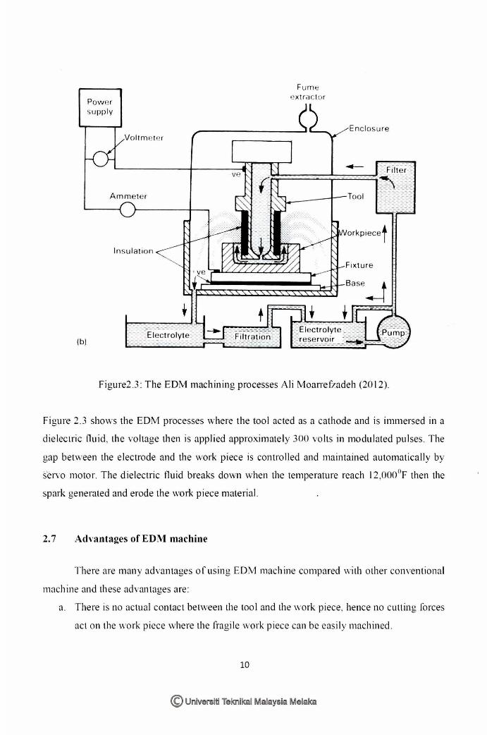
Figure2.3 : The ED 1 machining processes Ali l'vtoarrefzadeh (2012).
Figure 2.3 shows the EDM processes \vhere the tool acted as a cathode and is immersed in a
dielectric fluid. the voltage then is applied approximately 300 vo lts in modulated pulses. The
gap bet\\·een the electrode and the work piece is controlled and maintained automatical ly by
servo motor. The dielectric fluid breaks down \>,:hen the remperarure reach I 2,000°F then the
spark generated and erode the work piece material.
2. 7 Advantages of ED.M machine
There are many advantages of using ED\1 machine compared v.:ith other conventional
machine and these advantages are:
a. There is no actual contact between the tool and the work piece, hence no cutting forces
act on the \\·ork piece where the fragile work piece can be easily machined .
10
© Universiti Teknikal Malaysia Melaka