ez iii technical manual - digi-star · ez iii technical manual fort atkinson, wisconsin usa...
TRANSCRIPT

D3739-US Rev D April 2013
EZ III
Technical
Manual
Fort Atkinson, Wisconsin USA
Panningen, The Netherlands
www.digi-star.com


Technical Manual
D3739
Manual Updates and Corrections
Efforts have been made to make this document accurate and useful for Digi-Star service centers. Reader input is important and changes to improve this document are important to keep up with product changes and to correct errors.
Please contact your Digi-Star service representative if you wish to suggest changes or make corrections to this document.
Applicable Products
EZ2400, EZ2410, SW2600
EZ2500 (low profile housing)
EZ3400, ST3400, UM2510
EZ3600, UM2520
EZ400, GT400, SW300, SW600 (compact housing)
EZ4600, SW4600
GT460, NT460, UM510, UM512, UM520
Reference Documents
D3586 – Direct Access Numbers – change settings on keypad based indicators
D3605 – Software Release Information – software version & type used by model
D3648 – Escape Computer Commands – RS232 serial commands and print formats
D3657 – Long Form Setup – factory settings for indicators
F3471 – Setup and Calibration Numbers
F3471 Appendix A & B – Setup & Calibration guides
D3672 – Docking Station Commands
400931 – Wiring Tables
D3944 – 405404 Jumpers & Wiring Reference
D3708 – Analog Output Operators Manual
Option Kits referenced at back of this manual
Remotes referenced at back of this manual
Other documents available at www.Digi-Star.com
EZ III
Table of Contents EZ III Series Specifications ............................................................................................... 1 Power (J901) ...................................................................................................................... 1 Load Cells (J902, EZ Mate, Crown) .................................................................................. 2 Remote (J903) .................................................................................................................... 3 Remote Settings; D.A.N. 234 ............................................................................................ 3 Serial Ports ........................................................................................................................ 4
Communications ......................................................................................................... 4 Serial / Printer J904 .................................................................................................... 5 Example Printer Setup ................................................................................................ 5 Serial Com1-2 J905 .................................................................................................... 6 Computer Port (DB-9) ................................................................................................. 7 EID Reader Port (DB-9) .............................................................................................. 7 GPS Port (DB-9) ......................................................................................................... 7 DataKey Port .............................................................................................................. 8 USB Port .................................................................................................................... 8
Interfaces and Controls .................................................................................................... 8 Electronics/ Setup ............................................................................................................. 9
Main Board Connection Points, 404355 Base Rev A, B, C, D, E ................................ 9 Main Board Connection Points, 406970 Base Rev B .................................................. 9 Main Board Connection Points, (EZ2500V) 406658 Base Rev A ............................... 9 Main Board Connection Points, (EZ2500V) 406658 Base Rev B, C ......................... 10 Main Board Connection Points, (EZ/GT400, SW600) 405917 Base C, D ................. 10 Main Board Connection Points, (SW300) 404911 Base Rev B ................................. 10 Main Board Jumpers, 404355 Base Rev A, B, C, D, E ............................................. 11 Main Board Jumpers, 406970 Base Rev B ............................................................... 11 Main Board Jumpers, (EZ2500V) 406658 Rev A, B, C ............................................. 11 Main Board Jumpers, (EZ/GT400, SW600) 405917 Base Rev C, D ......................... 12 Main Board Jumpers, (SW300) 404911 Base Rev B ................................................ 12 Option Board Connection Points, 404379 & 405404 Base ....................................... 13 Option Board Connection Points, 408189 Base Rev B ............................................. 13 Option Board Connection Points, (EZ/GT400) 404005 Base Rev C ......................... 13 Option Board Connection Points, 405702 (Battery Option)....................................... 13 Option Board Jumpers, 404379 Base (404380, 404381, etc) ................................... 14 Option Board Jumpers, 405404 Base (405405, 405511, 405512, etc) ..................... 14 Option Board Jumpers, 408189 Base Rev B (408190, 408191, 408561) ................. 15 Option Board Jumpers, (EZ/GT400) 404005 Base Rev C ........................................ 15
Software Installation/ Configuration .............................................................................. 16 Calibrating the Scale Indicator ....................................................................................... 17
Long Form Vs Short Form Calibration Method ......................................................... 17 Calibrating the Scale for Maximum Accuracy (Long Form) ....................................... 17 Determining the New Setup and Calibration ............................................................. 17 Enter a New Setup and Calibration Number (Short Form) ........................................ 18
Self Test ........................................................................................................................... 18 Weighing Errors .............................................................................................................. 19
OVRCAP (Capacity Limit) ......................................................................................... 19 +RANGE (Over Range) ............................................................................................ 19 -RANGE (Under Range) ........................................................................................... 19
Indicator Functions and Direct Access Numbers Numbers (D.A.N.) .......................... 20 Menu 1 ..................................................................................................................... 23 Menu 2 ..................................................................................................................... 27 Menu 3 ..................................................................................................................... 35 Menu 4 ..................................................................................................................... 38 Menu 5 ..................................................................................................................... 44 Calibration ................................................................................................................ 48
Option Upgrade Kits........................................................................................................ 50 Remote Options ............................................................................................................... 52 Cable Repair & Adaptor Kits .......................................................................................... 53 Keypad Error Codes ........................................................................................................ 53 Software Error Codes...................................................................................................... 55 Print Formats ................................................................................................................... 56

Technical Manual
D3739 1
EZ III Series Specifications
Accuracy: 0.1% with System Accuracy based on load cells used
Temperature Range: -20 to +140 degrees F (-29C to +60C)
Enclosure Rating: IP65, IEC 529 (protected against dust and low pressure water)
Supply Voltage: 10.5 to 16.0 VDC (10.2 to 16.0 for EZ2500V) SW300 uses 2 AA batteries or AC wall adapter
Current with 4 Load Cells: 160mA (current load increases with additional hardware options)
Current with 8 Load Cells: 300mA (current load increases with additional hardware options)
10 Load Cell Maximum for full size indicators EZ400/ GT400/ SW600 are 8 Load Cell Maximum SW300 is 4 Load Cell Maximum (1 Stock Weigh platform)
3 Remote Display Maximum: Use up to 3 standard remotes (2 RD4000 remotes maximum) (EZ2500V & EZ/GT400 limited to 1 RD4000 remote + 1 RD2500V)
Fuses
F1 Main Fuse, internal: 2A tube style 5x20mm – Protects combined current of indicator, load cells, remote display(s), J905, and other indicator powered accessories. Excludes SW300 series
Note: Adding accessories such as radio modules and remote displays
will increase total current load, especially RD4000 devices. Refer to accessory documentation for additional power details.
F2 Relay Fuse, internal: 10A tube style 5x20mm; excludes EZ2500V, SW300, EZ/GT400, and SW600 series – Protects J901 power connector pin 3 relay as used in alarm relay output and machine control applications.
Power (J901)
Pin Wire Color Description
1 Red +12 Volts DC
2 Black Ground
3 Orange Relay/ Alarm Output; +12V (Scale Specific)
4 Blue Remote Input; Ground Signal (Scale Specific)

EZ III
2
Load Cells (J902, EZ Mate, Crown) There are 3 main types of load cell connectors in use, Standard, EZ Mate, and Crown connections. Standard typically requires a J-box to connect the load cells, while EZ Mate and Crown are designed for direct connection to the indicator. See special EZ2500V internal connections on next page.
Standard EZ Mate
Crown
Standard – Single Connector, use with J-Box
Pin Wire Color Board Connection Description
1 Red E15/ E19 + Excitation
2 Green E17/ E21 - Signal
3 White E16/ E20 + Signal
4 Black E18/ E22 - Excitation & Shield
EZ Mate – 4 Connectors
Pin Wire Color Board Connection Description
1 Red E15/ E19 + Excitation
2 Green E17/ E21 - Signal
3 White E16/ E20 + Signal
4 Black E18/ E22 - Excitation & Shield
5 (mid) Black E18/ E22 - Excitation & Shield
Crown – 4 Connectors
Pin Wire Color Board Connection Description
A Green E15/ E19 - Signal
B Red E17/ E21 + Excitation
C White E16/ E20 + Signal
D Black E18/ E22 - Excitation & Shield
E Black E18/ E22 - Excitation & Shield

Technical Manual
D3739 3
Note: EZ2500V series indicators have a terminal block connection to the main board. Wiring is shown
below; pin 1 is marked in small print on older revisions, colors are labeled on Rev E boards and newer.
Pin Wire Color Board Connection Description
1 Red TB2 – 1 + Excitation
2 Black TB2 – 2 - Excitation & Shield
3 Green TB2 – 3 - Signal
4 White TB2 – 4 + Signal
5 Shield TB2 – 5 Not Connected
Remote (J903)
The Remote connector carries power and data lines out to any EZ Series Remote indicator. Compatible remote displays include RD2000, RD2400V, RD2500V, RD4000, and RD400/ 440.
Note: EZ2500V uses location P3, EZ/GT400 uses P2
Pin Wire Color Connector Pin Description
1 Red (Thin) P2-1 +12V Unregulated
2 Red (Thick) P2-2 +12V Unregulated
3 White P2-3 Remote Zero Input
4 Green P2-4 Remote Data Out
5 Yellow P2-5 Remote Clock Out
6 Black (Thin) P2-6 GND
7 Blue P2-7 Pulsed Output
8 Black (Thick) P2-8 GND
Remote Settings; D.A.N. 234
There are 3 types of Digi-Star remote display hardware; EZ2, EZ3MUX, and COG. The setting for each remote type can be changed within indicator Menu 2 or D.A.N. 234, “RMDISP”.
EZ2 – set to EZ2 for:
RD2000(V), RD2500V, RD400/440, RD4000, and RD2400V serial numbers of 2000 or higher or remotes with 405386 adapter board
All older EZ2 series remotes must use the “EZ2” setting or they may not work.
EZ3MUX – set to EZ3MUX for:
RD2400V, RD2500V
First generation RD2400V series remotes must use the “EZ3MUX” setting, optional on others.
COG – set to COG for:
RD2500V series remotes
Optional setting for 2500 Chip-On-Glass series remotes; RD2500V can use any setting

EZ III
4
Serial Ports
The serial port connector has the capability of communicating using up to 2 different RS232 ports and a 20mA Current Loop port. The serial port can be a J904 or a J905 configuration on the EZ series, or can use the DB-9 style connectors for the Stock Weigh Series. A DB-9 style connection is also used on some models for EID reader, GPS, and other functions. Serial port connections also have the ability to interface with third party wireless controls and systems.
Communications
Data is transmitted and received in the asynchronous ASCII format. This communication format is compatible with most printers, computers, and terminals. On software versions 8.0 and higher, the parity and baud rate can be changed to fit a specific application. These settings are stored in MENU 2, or can be accessed through the D.A.N. numbers. See “Setup & Direct Access Number” section in this manual for further details and options.
Standard Configuration (AUTO, 7E1) Optional Setup (8N1 set w/ D.A.N. 271)
1 Start Bit 1 Start Bit
7 Data Bits 8 Data Bits
EVEN Parity Bit NONE Parity Bit
1 Stop Bit 1 Stop Bit
Baud Rate
The default Baud rate is either 1200 or 9600. The COM IN setting determines the baud rate unless SCOREM is set to 4, 24, 24 or 44 (See DAN 213), or if changed with one of the baud rate settings.
COM IN Default Baud Rate (D.A.N. 275)
DOWNLD 1200
EZ CMD 1200
EZ2CMD 9600
Changing Baud Rate Settings
On software versions 8.0 and higher, the baud rate can be changed to fit a specific application. These settings are stored in MENU 2, or can be accessed through the D.A.N. numbers. D.A.N. number 275 has COM 1 options of AUTO (default), 1200, 2400, 4800, and 9600. When set to AUTO, the baud rate is defaulted to the COM IN and Scoreboard settings as shown above.
"Handshake lines" are not used and XON/XOFF is not supported.
NOTE: For more information on data communications, refer to manual D3648 (Escape Computer Commands Set) and D.A.N. number section later in this manual.

Technical Manual
D3739 5
SERIAL / PRINTER J904
The J904 port is an option on many indicator models. Some models or option boards use a plug-in style harness, which may have a different board connection than shown below. Always refer to the proper schematic revision to verify wiring connections.
J904 is an optional jumper configuration on the EZ2500V series, using plug in connection P4.
Pin Wire Color Board Connection Description
1 Violet E5A 20ma Current Loop (+)
2 Orange E6A Printer Data out (Tx)
3 Red E8A Computer Data in (Rx)
4 Brown E7A Scoreboard Data out (Tx)
5 Gray E9 Computer GND
6 Blue E9 Printer GND
7 Black E10 Scoreboard GND
8 Black E10 20ma Current Loop (-)
Connecting J904 to a Printer
RS-232 Out Pin 2
Printer Ground Pin 6
Connecting J904 to a Computer or Wireless Machine Control
RS-232 In Pin 3
RS232 Out Pin 2
Computer Ground Pin 6
Connecting J904 to a Scoreboard
RS-232 Out Pin 4
Scoreboard Ground Pin 7
Connecting J904 to a 20mA current Loop Device
20mA Current Loop(+) Pin 1
20mA Current Loop(-) Pin 8
EXAMPLE PRINTER SETUP This is an example of the steps needed to run a 12 volt in-cab printer on Com 1 with >8.0 software. This printer example runs at ‘4800 baud’ with parity settings of ‘8 data bits’, ‘No parity’, and ‘1 stop bit’.
1) Attach printer cable to Serial port; connector pin 2 to indicator TX and pin 6 to indicator ground. (‘Connecting J904 to a Printer’ pg 5)
2) Set indicator Com 1 parity to 8N1. Type 271 and press ‘Select’ if you have a keypad, or enter Menu 2 to get to setting “C1-1PA”. Press ‘Select’ until “8N1” is displayed, then ON to save. (D.A.N. pg 34)
3) Set indicator Com 1 baud to 4800. Type 275 and press ‘Select’ if you have a keypad, or enter Menu 2 to get to setting “C1-1BD”. Press ‘Select’ until “4800” is displayed, then ON to save. (D.A.N. pg 34)
4) Turn power off then back on. Press ‘Print’ key a few times to verify data prints correctly.

EZ III
6
SERIAL COM1-2 J905
The J905 port is offered as an option on many indicator models. J905 is similar to J904 but provides an additional bi-directional port and a +12 VDC supply. Existing printers and printer cables will work with this port. Serial powered remote displays may also work on this port. Some models or option boards use a plug-in style harness, which may have a different board connection than shown below.
The EZ2500V series uses plug-in board connection P4. The EZ/GT400 & SW600 series use different board connections; see production prints and schematic. Always refer to the proper schematic revision to verify wiring connections.
Pin Wire Color Board Connection Description
1 Violet E5A 20ma Current Loop (+)
2 Orange E6A Com # 1 Out (Tx)
3 Red E8A Com # 1 In (Rx)
4 Brown E7A Com # 2 Out (Tx)
5 Gray or Yellow E29 +12 VDC (500mA)
6 Black E10 GND
7 Blue E35A Com # 2 In (Rx)
8 Black E10 20ma Current Loop (-)
Connecting J905 to a Printer / Scoreboard Com 1
RS-232 out Pin 2
Printer Ground Pin 6
Connecting J905 to a Printer / Scoreboard Com 2
RS-232 out Pin 4
Printer Ground Pin 6
Connecting J905 to a Computer or Wireless Machine Control COM 1
RS-232 In Pin 3
RS232 Out Pin 2
Computer Ground Pin 6
Connecting J905 to a Computer Com 2
RS-232 In Pin 7
RS232 Out Pin 4
Computer Ground Pin 6
Connecting J905 to a 20mA Current Loop Device
20mA Current Loop(+) Pin 1
20mA Current Loop(-) Pin 8
Connecting J905 to a Serial Remote Display COM 1
+12 VDC (500mA Max) Pin 5
GND Pin 6
RS232 Out Pin 2

Technical Manual
D3739 7
COMPUTER PORT (DB-9)
The Computer port is standard on the SW4600EID and SW2600EID models. The computer port is a bi-directional RS232 port that communicates with your PC or outputs data to a printer.
NOTE: The Internal connections column shows which pins are jumped on the connector.
Pin Desc. Internal Connections
1 DCD Connected to DTR & DSR
2 Data 3 Out
3 Data 3 In
4 DTR Connected to DCD & DSR
5 Ground
6 DSR Connected to DCD & DTR
7 CTS Connected to RTS
8 RTS Connected to CTS
9 Not Used
EID READER PORT (DB-9)
The EID Reader port is standard on the SW4600 EID and SW2600 EID models. The EID Reader port connects to an EID reader to input the tag data to the scale when weighing animals with EID tags.
Pin Description
1 DCD
2 Data 4 Out
3 Data 4 In
4 DTR
5 Ground
6 DSR
7 CTS
8 RTS
9 Not Used
GPS PORT (DB-9) The GPS port is standard on the NT460 and other equipped models.
Pin Wire Color Board Connection Description
2 Yellow E35B Data In
3 Orange E7B Data Out
5 Black E9 Ground
8 Black E9 Ground
9 Red E12 +5V

EZ III
8
DATA KEY PORT The Data Key port is used on certain EZ3600 and EZ4600 models, and is a data storage and transfer system similar in function to a USB. A docking station is required to read the DataKey. This port is discontinued on current models and has been replaced with a USB port.
USB PORT The USB port is available on several mid to high end indicators, including EZ3600, EZ4600, GT460, and NT460 models. Functions and applications of the USB vary slightly between models, but the primary purpose of the USB is to store or transfer data. See your models Operations manual for details on the product specific use of the USB port.
Interfaces and Controls Several indicator models require controls, interfaces, or special cables in order for the entire system to work as designed. The items below are only a partial list, and only include items required to be installed for the scale system to work correctly.
ST3400 Normally needs a control box and/ or cable to interface to the seed tender
GT460/ NT460 Auto Log units require a rotation counter and Y cable to work correctly
Touch screens Systems using a touch screen need serial and/ or power interface cables
Radio/ Cab Control Radio systems require hardware in at least 2 locations to communicate
NT460 GPS needed to track and map spreading location
UM520 & 2520 System specific interface cable required for indicator to function
EZ3600/ 4600 DK Data Key devices require a docking station to read data on PC

Technical Manual
D3739 9
Electronics/ Setup The EZ3 series indicators have several different style main circuit boards and multiple option boards. An attempt has been made to include as many types and revisions as possible. Always consult the schematic for the proper part number and revision before changing jumpers or wiring locations. Jumpers must be properly configured for the scale indicator to function. Contact Digi-Star Customer Service for complete documentation or assistance in configuring your scale hardware.
MAIN BOARD CONNECTION POINTS, 404355 BASE REV A, B, C, D, E
E1 +12VDC E20 + Signal (From Load Cell)
E2 Ground E21 - Signal (From Load Cell)
E3 Remote Alarm Out + E22 - Excitation (Analog Ground)
E4 Rotation Counter Input E23 Shield (Analog Ground)
E14 Ground E24 Shield (Analog Ground)
E15 + Excitation (Analog +8V) E25 + 12V Switched
E16 + Signal (From Load Cell) E26 + 12V Switched
E17 - Signal (From Load Cell) E27 + 12V Unregulated
E18 - Excitation (Analog Ground) E28 + 12V Switched
E19 + Excitation (Analog +8V) E31 Ground
MAIN BOARD CONNECTION POINTS, 406970 BASE REV B
E1 +12VDC E20 + Signal (From Load Cell)
E2 Ground E21 - Signal (From Load Cell)
E3 Remote Alarm Out + E22 - Excitation (Analog Ground)
E4 Rotation Counter Input E23 Shield (Analog Ground)
E14 Ground E24 Shield (Analog Ground)
E15 + Excitation (Analog +8V) E27 + 12V Unregulated
E16 + Signal (From Load Cell) E28 + 12V Switched
E17 - Signal (From Load Cell) J4 COG display
E18 - Excitation (Analog Ground) P8 COG backlight
E19 + Excitation (Analog +8V) P2 Remote Connector
MAIN BOARD CONNECTION POINTS, (EZ2500V) 406658 BASE REV A
TB1-1 +12VDC P5 TR kit connection
TB1-2 Ground J2 COG display
TB2-1 + Excitation (Analog +8V) P6 COG backlight
TB2-2 - Excitation (Analog Ground) P3 Remote Connector
TB2-3 - Signal (From Load Cell) P4 Serial Connector (12V is Max 500mA)
TB2-4 + Signal (From Load Cell)
TB2-5 Shield

EZ III
10
MAIN BOARD CONNECTION POINTS, (EZ2500V) 406658 BASE REV B, C
TB1-1 +12VDC P5 TR kit connection
TB1-2 Ground J2 COG display
TB1-3 Remote Input P6 COG backlight
TB2-1 + Excitation (Analog +8V) P3 Remote Connector
TB2-2 - Excitation (Analog Ground) P4 Serial Connector (12V is Max 500mA)
TB2-3 - Signal (From Load Cell) P7 Development interface
TB2-4 + Signal (From Load Cell)
TB2-5 Shield
MAIN BOARD CONNECTION POINTS, (EZ/GT400, SW600) 405917 BASE REV C, D
E1 +12VDC E15 + Excitation (Analog +8V)
E2 Ground E16 + Signal (From Load Cell)
E3 Remote Input E17 - Signal (From Load Cell)
E5 +5V E18 - Excitation (Analog Ground)
E6 Com 1 Out (TX) E19 + Excitation (Analog +8V)
E8 Com 1 In (RX) E20 + Signal (From Load Cell)
E9 Ground E21 - Signal (From Load Cell)
E10 20mA Current Loop E22 - Excitation (Analog Ground)
E12 +12VDC switched E23 Shield (Analog Ground)
E14 Ground E24 Shield (Analog Ground)
J2 Com 2 Serial Connections J6 Option Pcb Serial Connection
J3 Serial Connector P2 Remote Connector
J4 Option Pcb Communications
MAIN BOARD CONNECTION POINTS, (SW300) 404911 BASE REV B
J2 (+) +12VDC J3 Load Cell colors as marked on pcb
J2 GND Ground J4 Option jumpers & programming
J2SGND Switched Ground (adapter plug) W4 TXD (future use)
J1 RED Battery Holder + W5 RXD (future use)
J1 BLK Battery Holder -
Technical Manual
D3739 11
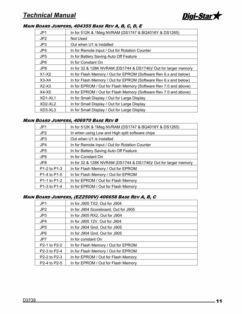
MAIN BOARD JUMPERS, 404355 BASE REV A, B, C, D, E
JP1 In for 512K & 1Meg NVRAM (DS1747 & BQ4016Y & DS1265)
JP2 Not Used
JP3 Out when U1 is installed
JP4 In for Remote Input / Out for Rotation Counter
JP5 In for Battery Saving Auto Off Feature
JP6 In for Constant On
JP8 In for 32 & 128K NVRAM (DS1744 & DS1746)/ Out for larger memory
X1-X2 In for Flash Memory / Out for EPROM (Software Rev 6.x and below)
X3-X4 In for Flash Memory / Out for EPROM (Software Rev 6.x and below)
X2-X3 In for EPROM / Out for Flash Memory (Software Rev 7.0 and above)
X4-X5 In for EPROM / Out for Flash Memory (Software Rev 7.0 and above)
XD1-XL1 In for Small Display / Out for Large Display
XD2-XL2 In for Small Display / Out for Large Display
XD3-XL3 In for Small Display / Out for Large Display
MAIN BOARD JUMPERS, 406970 BASE REV B
JP1 In for 512K & 1Meg NVRAM (DS1747 & BQ4016Y & DS1265)
JP2 In when using Low and High split software chips
JP3 Out when U1 is installed
JP4 In for Remote Input / Out for Rotation Counter
JP5 In for Battery Saving Auto Off Feature
JP6 In for Constant On
JP8 In for 32 & 128K NVRAM (DS1744 & DS1746)/ Out for larger memory
P1-2 to P1-3 In for Flash Memory / Out for EPROM
P1-4 to P1-5 In for Flash Memory / Out for EPROM
P1-1 to P1-2 In for EPROM / Out for Flash Memory
P1-3 to P1-4 In for EPROM / Out for Flash Memory
MAIN BOARD JUMPERS, (EZ2500V) 406658 BASE REV A, B, C
JP1 In for J905 TX2, Out for J904
JP2 In for J904 Scoreboard, Out for J905
JP3 In for J905 RX2, Out for J904
JP4 In for J905 12V, Out for J904
JP5 In for J904 Gnd, Out for J905
JP6 In for J904 Gnd, Out for J905
JP7 In for constant On
P2-1 to P2-2 In for Flash Memory / Out for EPROM
P2-3 to P2-4 In for Flash Memory / Out for EPROM
P2-2 to P2-3 In for EPROM / Out for Flash Memory
P2-4 to P2-5 In for EPROM / Out for Flash Memory

EZ III
12
MAIN BOARD JUMPERS, (EZ/GT400, SW600) 405917 BASE REV C, D
JP1 In for constant On
JP2 In for main pcb serial port/ Out for option pcb serial port
JP3 In for main pcb serial port/ Out for option pcb serial port
X1 to X2 In for Flash Memory / Out for EPROM
X3 to X4 In for Flash Memory / Out for EPROM
X2 to X3 In for EPROM / Out for Flash Memory
X4 to X5 In for EPROM / Out for Flash Memory
MAIN BOARD JUMPERS, (SW300) 404911 BASE REV B
J4-6 to J4-7 In for constant On

Technical Manual
D3739 13
OPTION BOARD CONNECTION POINTS, 404379 & 405404 BASE
E9 Ground E7A Com 2 Out (TX)
E10 Ground E35A Com 2 In (RX)
E14 Ground (NA 404379A,B,C) E6B DB9 Port 1 Out (TX) (where populated)
E29 +12 VDC switched (NA 404379A,B,C) E8B DB9 Port 1 In (RX) (where populated)
E12 +5V (where populated) E7B DB9 Port 2 Out (TX) (where populated)
E5A 20mA Current Loop + E35B DB9 Port 2 In (RX) (where populated)
E6A Com 1 Out (TX) E30 DB9 Port 2 pin 9 (NA 404379A,B,C)
E8A Com 1 In (RX) P1 USB header (405404 series only)
OPTION BOARD CONNECTION POINTS, 408189 BASE, REV B
E9 Ground P4-1 20mA Current Loop +
E10 Ground P4-2 Com 1 Out (TX)
E14 Ground P4-3 Com 1 In (RX)
E12 +5V (where populated) P4-4 Com 2 Out (TX)
P1 USB header (where populated) P4-5 +12V SW or Gnd – see jumpers
E6B Com 3 Out (TX) (where populated) P4-6 Ground
E8B Com 3 In (RX) (where populated) P4-7 Com 2 In (RX) or Gnd – see jumpers
E7B Com 4 Out (TX) (where populated) P4-8 Ground
E35B Com 4 In (RX) (where populated)
OPTION BOARD CONNECTION POINTS, (EZ/GT400) 404005 BASE, REV C
GND Ground TX1 Com 1 Out (TX)
GND Ground RX1 Com 1 In (RX)
12V_SW +12V Switched TX2 Com 2 Out (TX)
P1 Communications with Main Pcb RX2 Com 2 In (RX)
OPTION BOARD CONNECTION POINTS, 405702 (BATTERY OPTION FOR FULL SIZE UNITS)

EZ III
14
OPTION BOARD JUMPERS, 404379 BASE (404380, 404381, ETC)
JP1 Real Time Clock on Option Board In for RTC on Option Board (Battery Required)
JP2 Rotation Counter In for Rotation Counter / Out for Remote Input
JP3 Analog Output Select 1 See Schematic Jumper Table
JP4 Analog Output Select 2 See Schematic Jumper Table
JP5 Analog Out Current Loop In for Current Loop / Out for 0-5V
JP6 Analog Out Voltage In for 0-5V / Out for Current Loop
JP7 Not Used Always Out
JP8 Transmit Radio In for Radio
JP9 Transmit RS232 #2 Out for J904 except w/Radio / In for J905
JP10 Scoreboard Out In for J904 except w/Radio / Out for J905
JP11 Not Used Always Out
JP12 Not Used Always Out
JP13 Receive RS232 #1 Always In
JP14 Receive Radio In for Radio
JP15 Not Used Always Out
JP16 Receive RS232 #2 Out for Radio
E6A-E6B DB9 Connector J1 In for StockWeigh / Out for EZ
E7A-E7B DB9 Connector J2 In for StockWeigh / Out for EZ
E8A-E8B DB9 Connector J1 In for StockWeigh / Out for EZ
E35A-E35B DB9 Connector J2 In for StockWeigh / Out for EZ
OPTION BOARD JUMPERS, 405404 BASE (405405, 405511, 405512, ETC)
JP1 Analog Output Select 1 (RSEL1) See Schematic Jumper Table
JP2 Analog Output Select 2 (RESL2) See Schematic Jumper Table
JP3 Rotation Counter In for Rotation Counter / Out for Remote Input
JP4 Real Time Clock on Option Board In for RTC on Option Board (Battery Required)
JP5 Analog Out Voltage (VOUT) In for 0-5V / Out for Current Loop
JP6 Analog Out Current Loop (IOUT) In for Current Loop / Out for 0-5V
JP7 Radio CTS/ Not Used Typically Out
JP8 Transmit Radio (COM2 TX) In for Radio
JP9 Transmit RS232 #2 (J905 pin 4) Out for J904 except w/Radio / In for J905
JP10 Scoreboard Out (COM1 TX) In for J904 except w/Radio / Out for J905
JP11 Radio RTS/ Not Used Typically Out
JP12 Com 1 RX E8B or DB9 J2 Typically Out
JP13 Receive RS232 #1 (J904/5 pin 3) Always In
JP14 Receive Radio (COM2 RX) In for Radio
JP15 Com 2 RX E35B or DB9 J1 Typically Out
JP16 Receive RS232 #2 (J905 pin 7) Out for Radio
JP17 Enable U11 (NA rev A, B, C) Enable U11 & U12 (2nd RS232) serial outputs
E6A-E6B DB9 Connector J1 In for StockWeigh / Out for EZ
E7A-E7B DB9 Connector J2 In for StockWeigh / Out for EZ
E8A-E8B DB9 Connector J1 In for StockWeigh / Out for EZ
E35A-E35B DB9 Connector J2 In for StockWeigh / Out for EZ

Technical Manual
D3739 15
OPTION BOARD JUMPERS, 408189 BASE REV B (408190, 408191, 408561, ETC)
OPTION BOARD JUMPERS, (EZ/GT400) 404005 BASE REV C (J905 W/ RTC)
J1, J3, J5, J7 Selects Serial Port Com lines In for J905 functions/ Out for Radio
J2, J4, J6, J8 Selects Radio Com lines In for Radio/ Out for J905
J9 thru J13 Selects Development Connection Connect X2 thru X6
J14 Real Time Clock Enable In for RTC (Battery Required)

EZ III
16
Software Installation/ Configuration Since there are different main board types, there are also different software chip types to use. The basic configurations are included below. See D3605 for current software release information. Please contact an authorized service center or Digi-Star Customer Service if needing to update or replace software, as indicator setting changes may occur. Always download or backup any scale data prior to making any software changes.
Note: Information excludes SW300 series; requires factory programming
SINGLE 1M EPROM – Single software IC can be used on all EZ3 indicators. 2 jumpers must be
installed at the “PROM” locations on the main board.
SINGLE 512K FLASH – Single software IC that is used on basic featured EZ3 indicators. 2 jumpers
must be installed at the “FLASH” locations on the main board.
DOUBLE 512K FLASH – Two software ICs that each contain half of the software program. These are
labeled as “HI” and “LO” on the IC and their location on the main board. This configuration is used on main boards equipped with two software sockets. 2 jumpers must be installed at the “FLASH” locations on the main board, and jumper installed at JP2 to enable the double IC configuration.

Technical Manual
D3739 17
Calibrating the Scale Indicator
Your Digi-Star scale indicator can be mated to many different types of load cells with varying capacity. There can be as few as 1 and as many as 10 load cells on a system, based on model number and type. The scale indicator has a "setup" number that determines how the scale displays the weight, and a "calibration" number that matches the load cells to the indicator and determines the weight value displayed on the indicator.
LONG FORM VS SHORT FORM CALIBRATION METHOD
Long form calibration requires you to have some known accurate weights to load onto the scale. If done properly, this is the best way to calibrate your scale accurately.
Short form calibration requires you to know the load ratings on the load cell, the number of load cells and other factors. A calibration number can be calculated and entered directly into the scale.
CAUTION: The short form calibration method works with Digi-Star load cells only. The short form calibration method for a non-Digi-Star load cell may get close to the correct calibration number, but this method is not reliable and the scale calibration must be checked using known weights.
CALIBRATING THE SCALE FOR MAXIMUM ACCURACY (LONG FORM)
Write down the current Setup and Calibration numbers of your EZ indicator. These numbers are displayed during the Self Test. Press [On/Off] to "pause" the Self-Test while setup and calibration numbers are displayed. Press [On/Off] again, to "resume"
Setup Number _______________ Calibration Number ________________
To accurately calibrate the scale, you will need a large amount of weight that has a known value. For best results you should have at least as much weight as the largest load you plan to weigh.
DETERMINING THE NEW SETUP AND CALIBRATION
1. Zero-Balance the scale so the display reads zero.
2. Put the Known Weight on the scale platform and write down the Weight Display.
Perform the following equation to find the Accurate Calibration Number.
Actual Known Weight X Existing Calibration Number Displayed Weight
Example:
Actual Known Weight 2000lbs
Weight Display 2080lbs.
Existing Cal Number 32500.
2000 X 32500 = 31250 2080
31250 is the “Accurate Calibration Number”. The setup number does not change.

EZ III
18
ENTER A NEW SETUP AND CALIBRATION NUMBER (SHORT FORM)
The Short Form Setup & Calibration procedure allows you to change the "SETUP" and "CAL" numbers of the indicator.
1. Press and hold [Zero], and then press [On/Off] for 3 seconds to enter the short form calibration.
2. The display will flash "SETUP" and then display the 6-digit setup number with the right digit flashing. To modify the setup number:
3. Press [Gross/Net] several times to increment the digit to it proper value.
4. Press [Tare] to advance the blinking digit to the left.
5. Repeat steps 1 and 2 for each digit as required.
6. Press [On/Off] to enter the new setup number and display the calibration number.
7. Repeat steps 1 and 2 to modify the calibration number.
8. Press [On/Off] to enter the new calibration number and the display will go back to normal.
9. Verify the accuracy of the scale.
Self Test
Initiating the Self Test
After turning the scale on, wait for normal operation to begin then press the ON key. The Self Test tests all settings, displays information, and performs an internal system check to ensure that the indicator is working and set properly.
On EZ2500V and EZ/GT400 models, press NET/GROSS then ON/OFF to start self test. On SW600 and SW300 models, press MENU then ON/OFF to start self test.
Test Sequence (Order may vary based on model & software version)
The word TEST flashes:
"SETUP" is displayed.
Display Setup Value: Short Form Setup Value.
Display Calibration Number: Short Form Calibration Value.
Display Temperature Calibration Count:
Display LCD Segments: The system then cycles through all display segments to help the operator identify any faulty areas.
Display Program ID: Displays the current version (revision number) of the software.
System Test: The indicator displays the message "RUNNING SELF TEST - PLEASE WAIT" while performing internal system testing. Self Test cannot be paused or terminated during this test.
Self Test System Errors:
If system errors are discovered during internal diagnostics, the operator will see an error message. For example, "ERROR 1 - PRESS NET/GROSS TO CONTINUE" followed by "*** INDICATOR NEEDS SERVICE *** PRESS NET/GROSS TO CONTINUE". See “Software Error Codes” near the end of this manual for error code descriptions.
Sending a command using the Computer Interface causes the system to terminate the error messages and attempt normal system operation.

Technical Manual
D3739 19
Pausing the Test:
Press [ON] during the self test to pause the sequence.
Press [ON] again to restart the test.
Terminating the Test:
The self-test terminates and continues normal operation if no errors are detected or if other keys are pressed.
Weighing Errors
OVRCAP (CAPACITY LIMIT)
The display shows the message "OVRCAP" if the weight on the scale system exceeds the capacity limit. The capacity value is entered in SETUP to warn of overloading the scale system.
+RANGE (OVER RANGE)
The display shows the message "+RANGE" if the weight on the scale system exceeds the maximum weight measurable by the scale system. The over range value is always the system's maximum A/D counts multiplied by the scaling factor. The actual weight at which over range occurs depends on the calibration, zero, and display count size.
-RANGE (UNDER RANGE)
The display shows the message "-RANGE" if the weight on the scale system is less than the minimum weight measurable by the scale system. The under range value is always the system's minimum A/D counts multiplied by the scaling factor. The actual weight at which under range occurs will depend on the calibration, zero, and display count size.

EZ III
20
Indicator Functions and Direct Access Numbers (D.A.N.)
MENU 1 - BASIC FEATURES IN MOST SCALES LANGUAGE {LANGAG}…………………………………………………………………………………….. 101 pg. 23 DISPLAY RATE {D RATE}………………………………………………………………………………… 102 pg. 23 MOTION {MOTION} .....................................………………………………………………….…………. 103 pg. 23 ZERO TRACK {ZTRACK} ............................…………………………………………………………….. 104 pg. 23 WEIGH METHOD {W MTHD} .......................……………………………………………………….……. 105 pg. 23 LOCK ON {LOCKON} ...................................………………………………………….…………………. 106 pg. 24 TR HOLD {TR HLD} ....................................…………………………………………………….………. 107 pg. 24 SCALE ID SETUP {SCALID} ......................………………………………………………….…………. 108 pg. 24 LOCK-N-HOLD {LKNHLD} ...........................……………………………………………….……………. 109 pg. 24 AUTO OFF {AUTOFF} .................................…………………………………………….………………. 111 pg. 24 LOCK ON STORE {L STORE} ....................…………………………………………….………………. 112 pg. 24 LSTORE SEND MODE {LSSEND} ..............………………………………………….…………………. 113 pg. 25 EID STORE {E STORE} .............................………………………………………….…………………. 114 pg. 26 1 PRESS ZERO {1 ZERO} .........................………………………………………….…………………. 115 pg. 26 POWER LOSS MESS {PWRLOS} ................……………………………………….……………………. 116 pg. 26 EID AUTO RECORD{EIDAUT} ...................……………………………………….……………………. 117 pg. 26 SCROLL DELAY {SCROLL} ........................……………………………………….……………………. 118 pg. 26 TR KEY FUNCTION {TRKEY1} ...................…………………………….………………………………. 121 pg. 26 FORCE PREMIS ENTRY{GINPIN} ............……………………………………….……………………. 123 pg. 26 SW4600 DEVIATION{SW DEV} ..................……………………………………….……………………. 124 pg. 26 MOTION WEIGHT{MOT WT} .......................……………………………………….……………………. 125 pg. 26 LOCK-ON TIME ADJ{LKTIME} ...................……………………………………….……………………. 126 pg. 27 CLEAR LOCK-ON AT ZERO{LKZERO} .......……………………………………….……………………. 127 pg. 27 MOTION LOCK SETUP{MOT LK} ..............…………………………………….………………………. 128 pg. 27 NO LOW BATTERY SENSING{NOLBAT}………………………………………………………………... 129 pg. 27 SAVE TARE{SAVTAR} ................................……………………………………….……………………. 131 pg. 27 NUMBER OF BINS{BINNUM}......................……………………………………….……………………. 132 pg. 27 NUMBER OF ROWS{ROWNUM} ...................……………………………………….……………………. 133 pg. 27 ROW MAX CAPACITY{ROWMAX} ................……………………………………….……………………. 134 pg. 27
MENU 2 - CLOCK, PRINTER, COMMUNICATIONS & ESTIMATED WEIGHT FEATURES TIME FORMAT {TIME F} ...........................………………………………………..……………………. 201 pg. 27 TIME {TIME} ...............................................………………………….……………….…………………. 202 pg. 27 DATE FORMAT {DATE F} ..........................……………………………………..………………………. 203 pg. 27 DATE {DATE} ..............................................………………………………………..……………………. 204 pg. 28 TARE AUTO PRINT {TAREAP} ...................……………………………………..………………………. 211 pg. 28 ONE LINE PRINT {1L PRT} .......................……………………………………..………………………. 212 pg. 28 SCOREBOARD MODE{SCOREM} ...............………………………………………..……………………. 213 pg. 28 AUTO PRINT {APRINT} ..............................……………………………………..………………………. 214 pg. 31 COMPUTER IN MODE {COM IN} ...............……………………………………..………………………. 215 pg. 31 PRINT FORMAT{PRTFMT} .........................……………………………………..………………………. 216 pg. 31 MEDIA TYPE{MEDIA} .................................………………………………………..……………………. 217 pg. 31 REMOTE{REMOTE} .....................................…………………………………………..…………………. 218 pg. 31 ZERO OUTPUT {ZEROUT} ..........................………………………………………………..……………. 219 pg. 31 COM 1 DELAY {C1 DLY} ...........................………………………..……………………………………. 221 pg. 31 COM 2 DELAY {C2 DLY} ...........................………………………..……………………………………. 222 pg. 31 PRINT ACCUMULATION{PRTACC} ............………………………..……………………………………. 223 pg. 32 RMT CC START STOP ENABLE{RMC EN}………………………………….………………………….. 224 pg. 32 RECORD SIZE{RECSIZ} ............................………………………..……………………………………. 225 pg. 32 SCALE NUMBER{SCL NO} ........................……………………..………………………………………. 231 pg. 32 REMOTE DISPLAY{RMDISP} .....................……………………..………………………………………. 234 pg. 32 PRINT KEY OPERATION{TARPRT} ...........……………………..………………………………………. 235 pg. 32 BAR GRAPH MODE{BARGRP} ....................……………………..………………………………………. 236 pg. 32 BAR GRAPH WEIGHT{BAR WT} ................……………………..………………………………………. 237 pg. 32 PRINT BUFFER{BUFFER}………………………………………………..……………………………….... 238 pg. 32 PB SCROLL BY LINES{PBLINE} ...............………………………………………………..……………. 239 pg. 33 ANALOG LOW WEIGHT{LOW WT} .............…………………………………………………..…………. 241 pg. 33 ANALOG HIGH WEIGHT{HIGHWT} ............…………………………………………………..…………. 242 pg. 33 ANALOG SELECT {ANAOUT}......................………………………………………………..……………. 243 pg. 33 NEGATIVE ANALOG OUTPUT {-ANALG}……………………………………………………………….. 244 pg. 33 FRONT PANEL ZEROUT{ZEROFP} ............………………………………………………..……………. 249 pg. 33 REMOTE TERMINAL {RMTERM} .................……………………………………………….…………….. 251 pg. 33 ISOBUS WEIGHT {ISO WT}.......................………………………………………………………….….. 252 pg. 33 OPERATING STATUS {OPSTAT} ...............……………………………………………………….…….. 253 pg. 33 REMOTE TERMINAL PORT {RMPORT} ......……………………………………………………….…….. 254 pg. 34 DISABLE RMPORT RESPONSE {RMNOPR}…….……………………………………………………..… 255 pg. 34

Technical Manual
D3739 21
MENU 2 - CLOCK, PRINTER, COMMUNICATIONS & ESTIMATED WEIGHT FEATURES (CONTINUED) ISOBUS BASE ADDRESS{ISOADR} ......... ………………………………………………………….……………. 256 pg. 34 DISABLE ISOBUS VT MESSAGE{ISO VT}………………………………………………………………………. 257 pg. 34 PRINT ON PIN 2 {PRNT-2} ....................... …………………………………………………….…………………. 261 pg. 34 COM 1-1 PARITY {C1-1PA} ...................... …………………………………………………………….…………. 271 pg. 34 COM 1-2 PARITY {C1-2PA} ...................... …………………………………………………………………….…. 272 pg. 34 COM 1-3 PARITY {C1-3PA} ...................... ……………………………………………………………….………. 273 pg. 34 COM 2 PARITY {C2 PA} ......................... ……………………………………………………………….………. 274 pg. 34 COM 1-1 BAUD RATE {C1-1BD}............... ………………………………………………………….……………. 275 pg. 34 COM 1-2 BAUD RATE {C1-2BD}............... ………………………………………………………….……………. 276 pg. 34 COM 1-3 BAUD RATE {C1-3BD}............... ………………………………………………………….……………. 277 pg. 34 COM 2 BAUD RATE {C2 BD} .................. ………………………………………………………….……………. 278 pg. 34 ESTIMATE WEIGHT {EST WT} ................. ………………………………………………………….……………. 299 pg. 34
MENU 3 - SCALE CALIBRATION SETTINGS DISPLAY COUNT {COUNT} ........................ ……………………………………………………………………….. 301 pg. 35 AUTO RANGE {ARANGE} ........................... ………………………………………………………………….……. 302 pg. 35 DISPLAY UNIT {LB-KG} ............................ ……………………………………………………….………………. 303 pg. 35 CAPACITY {CAP} ....................................... ………………………………………………………….……………. 304 pg. 35 WM1 ADJUST 1 {WMA1-1} ........................ …………………………………………………….…………………. 305 pg. 35 WM1 ADJUST 2 {WMA1-2} ........................ ……………………………………………………….………………. 306 pg. 35 WM1 ADJUST 3 {WMA1-3} ........................ …………………………………………………….…………………. 307 pg. 35 WM2 ADJUST 1 {WMA2-1} ........................ …………………………………………………….…………………. 311 pg. 35 WM2 ADJUST 2 {WMA2-2} ........................ …………………………………………………….…………………. 312 pg. 36 WM2 ADJUST 3 {WMA2-3} ........................ …………………………………………………….…………………. 313 pg. 36 MIMIC TYREL {TC1300} ........................... …………………………………………………….…………………. 321 pg. 36 APPLICATION 10KMH {10K TA} .............. …………………………………………………….…………………. 322 pg. 36 APPLICATION UNITS {A UNIT}…….………..…….……………………………………………………....…….… 323 pg. 36 APPLICATION RATE {RATE } .................. …….………………………………………………….……………… 324 pg. 36 APPLICATION WIDTH {WIDTH } .............. …….…………………………………………………….…………… 325 pg. 36 GPS STORAGE INTERVAL {GPSSTR} ...... …….…………………………………………………….…………… 326 pg. 37 TOTAL ACRES {ACRES } .......................... …….………………………………………………….……………… 327 pg. 37 APP RATE ESTIMATE {ARATE1} .............. …….……………………………………………………..…………... 331 pg. 37 APP RATE AVERAGE {ARATE2} .............. ………………………………………………………….……………. 332 pg. 37 APP RATE WINDOW {ARATE3} ................ …………………………………………………………………….…. 333 pg. 37 APP MINIMUM SAMPLES {ARATE4} ........ …………………………………………………………………….…. 334 pg. 37 APP RATE EQUAL WEIGHTS {AWEQUL}..……….…………………………………………………………….….. 335 pg. 37 APP RATE SPEED ADJUST {ARATE5} ..... …..…….……………………………………………….………….…. 336 pg. 37 APP RATE LOAD / UNLOAD {A L/UL} .... ……………………………………………………….………………. 337 pg. 38 A,B,C Display Format {ABCDSP} ................ …………………………………………………….…………………. 341 pg. 38
MENU 4 - PRESET, BATCHING & ROTATION COUNTER FEATURES PRE ALARM {P MTHD} & {P-ALM} ............ ……………………………………………………………………..… 401 pg. 38 REMOTE INPUT {RM INP} ....................... ……………………………………………………………………….. 402 pg. 38 ALARM OUTPUT {AL OUT} ...................... ……………………………………………………………………..… 403 pg. 38 BUZZER {BUZZER} .................................... ……………………………………………………………………..… 404 pg. 38 PRELOAD TARE {PRETAR} ....................... ………………………………………………………………….……. 405 pg. 38 RELAY {RELAY} ......................................... ………………………………………………………………….……. 406 pg. 39 UNLOAD ALARM {U ALRM} ...................... ………………………………………………………………….……. 407 pg. 39 REMOTE SWITCH MESSAGE {RI MSG}…………………………………………………………………………. 411 pg. 39 REMOTE SWITCH STATE {RISTAT} ........ ………………………………………………………………….……. 412 pg. 39 REMOTE SWITCH MSG {RITIME} ........... ………………………………………………………….……………. 413 pg. 39 TIMER/COUNTER {TMRCTR} ..................... ………………………………………………………………….……. 421 pg. 39 DRIVE RATIO {DRATIO} ............................ …………………………………………………………………….…. 422 pg. 39 SET POINT {SETPNT} ................................ ……………………………………………………………………….. 423 pg. 39 CHANGE WEIGHT {SETCHG} .................... …………………………………………………………………….…. 424 pg. 39 CHANGE DELAY {SETDEL} ...................... ………………………………………………………………….……. 425 pg. 39 SET OVER UNDER {SETOUT} ................... ……………………………………………………………….………. 426 pg. 40 SET POINT COUNTER {SETCTR} ............. ……………………………………………………………….………. 427 pg. 40 RECIPE KEYS {RECKEY} ........................... ……………………………………………………………….………. 438 pg. 40 PROGRAM RECIPE {PROGRM} .................. ……………………………………………………………….………. 439 pg. 40 ENTRY METHOD {E MTHD} ..................... ……………………………………………………………….………. 441 pg. 40 TOLERANCE {TOLER} ............................... ……………………………………………………………….………. 442 pg. 40 INGR.ADVANCE DELAY {DELAY} ............. ……………………………………………………………….………. 443 pg. 41 INGREDIENT NAMES {INGRNM} ............... …………………………………………………………….…………. 444 pg. 41

EZ III
22
MENU 4 - PRESET, BATCHING & ROTATION COUNTER FEATURES (CONTINUED) ACCUMULATION {ACCUM} .........................…………………………………………………………….. 445 pg. 41 FORCE USER ID {USERID} .......................…………………………………………………………….. 446 pg. 41 MEDIA STORAGE {MSTORE}......................…………………………………………………………..… 447 pg. 41 RESIZE 3500 RECIPE {RESIZE} ...............………………………………………………………….…. 448 pg. 41 INGREDIENT RE-SIZING {INGSIZ} ..........…………………………………………………………….. 449 pg. 41 RECIPE TOTAL {RECTOT} .........................…………………………………………….………………. 451 pg. 41 DISPLAY SCOOP % {SCOOP%} ..................…………………………………………………….………. 452 pg. 42 TOLER OVER LOCK {OVERLK} ..................………………………………………………….…………. 453 pg. 42 FEED ZONE {FDZONE} ...............................………………………………………………….…………. 454 pg. 42 UNDONE RECIPES {UNDN I} ...................……………………………………………….……………. 455 pg. 42 DISPLAY RECIPE PENS {RECPEN}……………………………………………………………………… 456 pg. 42 RANGE TEST {R TEST} ............................………………………………………………….…………. 457 pg. 42 AUTO START PENS {AUTPEN} ..................………………………………………………….…………. 458 pg. 43 ERASE DONE FEEDLINE {ERASFD} .........………………………………………………….…………. 459 pg. 43 MANUAL PEN ADVANCE {MANPEN} ..........………………………………………………….…………. 461 pg. 43 PEN TOL {T MTHD} & {PENTOL} ................………………………………………………….…………. 462 pg. 43 PEN WEIGHT {PEN WT} .............................………………………………………………….…………. 463 pg. 43 BATCH NUMBER {BATNUM} .......................………………………………………………….…………. 464 pg. 43 DOUBLE KEY {DBLKEY} ............................……………………………………………….……………. 465 pg. 43 RECIPE REMAIN ACTIVE {RE-USE} .........……………………………………………….……………. 466 pg. 43 RECIPE STARTED WEIGHT {RSTART} .....……………………………………………….……………. 467 pg. 43 RECIPE ENTRY METHOD {RENTRY} ........……………………………………………….……………. 468 pg. 44 PARTIAL FEEDING {PARTFD}....................……………………………………………….……………. 469 pg. 44 PEN STARTED WEIGHT {PSTART} ...........……………………………………………….……………. 471 pg. 44 SPLIT LOAD {SPLOAD} ...............................…………………………………………….………………. 472 pg. 44 NUMBER OF INGREDIENTS {NUMING} ....…………………………………………….………………. 473 pg. 44 STARTING PRESET WEIGHT {STPRST} ...…………………………………………….………………. 474 pg. 44
MENU 5 – CONTROL SETTINGS
DOOR SETUP {UGDOOR} .............................……………………………………………………………. 501 pg. 44 UV GRAIN SOLONOID {UG3SOL} ..............………………………………….…………………………. 502 pg. 44 PARTIAL LOAD {Truck } ..........................………………………………………………….…………. 503 pg. 44 SPLIT HOPPER ALARM {S ALRM} ............………………………………………………….…………. 504 pg. 45 SPLIT HOPPER PREALARM {SPALRM} .....……………………………………………….……………. 505 pg. 45 DOOR OPEN WEIGHT {DOOROW} ..............……………………………………………….……………. 506 pg. 45 DOOR DEBUG MODE {DDEBUG} ...............……………………………………………….……………. 507 pg. 45 DIAGNOSTIC ENABLE {DIAG } ..............……………………………………………….……………. 508 pg. 45 DOOR OPEN TIME {DOOROT} ....................………………………………………………….…………. 509 pg. 45 DOOR OPEN PERCENTAGE {DOOROP} ....………………………………………………….…………. 511 pg. 45 DOOR CLOSE TIME {DOORCT} ..................………………………………………………….…………. 512 pg. 46 DOOR CLOSE WINDOW {DOORWT} ...........………………………………………………….…………. 513 pg. 46 DOOR INSIDE WINDOW TIME {DOORIT}……………………………………………………………….. 514 pg. 46 DOOR PREALARM OFFSET {DOORPO} .....………………………………………….…………………. 515 pg. 46 DOOR PREALARM SCALER {DOORPS} ………………………………………….…………………. 516 pg. 46 ADAPTIVE AUGER WEIGHT MAX {AUGRMX}………………………………………………………….... 517 pg. 46 LEFTOVER AUGER WEIGHT {AUGRWT} ...………………………………………………….…………. 518 pg. 46 AUGER WEIGHT SCALAR GAIN {DRAWGN}…………………………………………………………….. 519 pg. 46 DOOR WEIGHT CLOSING {DOORWC} ........…………………………………………………….………. 521 pg. 47 RPM START/STOP CONTROL {RSSCTL}…………………………………………………………….…. 531 pg. 47 RPM STOP SPEED {RSSMIN} ....................…………………………………………………….………. 532 pg. 47 RPM START TOL SPEED {RSSTOL} ..........…………………………………………………….………. 533 pg. 47 RPM START DELAY {RSSTDY} ..................…………………………………………………….………. 534 pg. 47 RPM STOP DELAY {RSSPDY} ....................…………………………………………………….………. 535 pg. 47 RPM CONTORL {RPMCTL} ........................…………………………………………………….………. 536 pg. 47 RPM MINIMUM {RPMMIN} .........................…………………………………………………….………. 537 pg. 47 RPM TOLERANCE {RPMTOL} ....................…………………………………………………….………. 538 pg. 47 RPM DELAY {RPMDLY} ............................…………………………………………………….………. 539 pg. 48
CALIB - CALIBRATION TEMP CALIBRATION {T CALB} .................…………………………………………………………….. 801 pg. 48 DEAD WEIGHT CAL {CAL} .........................…………………………………………………………….. 802 pg. 48
SHORT FORM - CALIBRATION SETTINGS SETUP NUMBER {SETUP} .........................…………………………………………………………….. 871 pg. 49 CALIBRATION NUMBER {CAL} ................…………………………………………………………….. 872 pg. 49

Technical Manual
D3739 23
MENU 1
LANGAG (D.A.N. 101) Language
Select the language from the menu.
ENGLSH ....... English
NEDRL ......... Dutch
FRANCS ....... French
DEUTSH ....... German
ITAL .............. Italian
PORT ............ Portuguese
ESPAN ......... Spanish
DANSK ......... Danish
MAGYAR ...... Hungarian
VESTA .......... Special Spanish Translation for South America
D RATE (D.A.N. 102) Display Rate
Select the number of times per second to update the weight display. This setting also affects remote indicators. Default = “2”. Select 1, 2, 3, or 4. Note: When selecting the Weigh method (General, Slow, or Fast) or when setting the Weigh Method Adjustment Options (see Menu #3 of the Long Form Setup), a change in Display Rate affects how the weight appears on the scale. A selection of ‘1’ update per second helps to stabilize the weight. A selection of ‘4’ updates per second provides more response to weight changes but may cause the weight to appear “jumpy.”
MOTION (D.A.N. 103) Motion
Select On or Off. If set to On, an annunciator flashes under the word Motion on the display to indicate unstable weight.
The MOTION parameter limits operation if the scale is unstable. It does not correct for the instability. It is up to the operator to correct the unstable environment. The following items are disabled until the weight is stable:
- Printer output
- Zero/Balance function
- Tare function
- Ingredient Auto-advance
Note: Motion is temporarily turned on during all system weight calibrations to insure a stable measurement. It is turned off after calibration if Off was selected in Motion setup.
ZTRACK (D.A.N. 104) Zero Track
Zero-Track is typically used only for animal weighing applications. If "ON", the scale will adjust for small weight variances of up to 5lbs in the Lock-On weigh method. This allows the scale to compensate for such things as mud or snow accumulation on the scale platform.
W MTHD (D.A.N. 105) Weigh Method
Weigh method allows the operator to adjust how much processing or number-crunching the scale processor does to the load cell data before displaying the weight. 1 – General 2 – Slow 3 – Fast 4 – “Lock-on” (animal weighing)

EZ III
24
LOCKON (D.A.N. 106) Lock On
Available settings are 1 thru 10. A low value, such as a 1 or 2, allows the system to be more sensitive to animal motion. A high value, such as a 9 or 10, allows the scale to lock on faster. Use the lowest setting that still allows the system to lock on consistently. TRHOLD (D.A.N. 107) T/R Hold
ON Displays GROSS weight if T/R button is held for three (3) seconds. OFF Displays GROSS weight momentarily if T/R button is held for three (3) seconds. SCALID (D.A.N. 108) Assign Scale ID Number
This feature allows the operator to identify the scale with a (truck or mixer number). After entering the SCALID menu, the scale’s default name “NEW EZ” will be displayed on the screen. Press [CLEAR] several times (or hold ‘clear’ for 2 seconds) to clear out the existing number and enter the desired scale identification number or letter on the numeric keypad. Press [ON] to store the ID number and advance to the next menu item. (SCALID is used by TMR Tracker and other software programs for identification. SCALID is also ‘FIELD’ key function on several models.)
LKNHLD (D.A.N. 109) Lock and Hold
This feature continues to hold the Lock-On weight on the display for an animal after it has stepped off the platform. The operator can place the animal on the weighing platform, medicate, remove the animal from the platform and then record the animal's weight after it has stepped off the platform. The display will restart once another animal has stepped onto the platform and exceeds 2.5% of the scale capacity. For example if the scale capacity is set at 4000lbs, 100lbs is required to reset the display. The indicator will return to normal weighing after 5 minutes if no other animal steps on the weighing platform. The [RECHECK] key can be used to return the indicator to the weighing mode. AUTOFF (D.A.N. 111) Auto Off
This feature allows the operator to have the indicator automatically shut itself OFF after 15, 30, 45 or 60 minutes of inactivity. This feature will extend battery life on battery powered portable scales and equipment like seed tenders which use their own power supply or battery. Prior to the scale shutting off, the message "GOODBYE" will be scrolled across the display for approximately 15 seconds. Pressing a key on the indicator during this time will prevent the unit from turning off and restart the internal shut-off timer. A jumper on the main board is typically required for this function to operate. LSTORE (D.A.N. 112) Lock-On-Store
This feature allows the user to configure how and when weighing data is printed or sent to the computer port and stored into memory on the Indicator during animal weighing. Data that is stored into memory is retrieved using "StockWeigh Link" software.
Manual mode requires the operator to push [ON/RECORD] to store and/or send the data for each animal. The automatic mode allows the data to be stored and/or sent either by pressing the [ON/RECORD] button, after the scale "Locks-On" or when the animal steps off the platform. In the following four “LSTORE” modes, print data is sent to the computer connector on the
StockWeigh indicator (printer port on other models). Data is not stored in memory.
MANPRT (Manual Print) - Indicator does not accept EID data -- Indicator does not store data in memory -- Sends time, date, and weight data to computer port when operator presses the [ON/Record] key -- Set PRTFMT to select desired print format.
AUTPRT (Automatic Print) - Indicator does not accept EID data -- Indicator does not store data in memory -- Sends Time, Date, and Weight data to the computer port when the scale locks-on or when the animal steps off the platform -- Set LSSEND to select when data is sent -- Set PRTFMT to select desired format.

Technical Manual
D3739 25
MAN WT (Manual Weight) - Indicator accepts EID data -- Message will not alert operator if EID data is missing -- Indicator does not store data in memory -- Sends EID, time, date, and weight data to the computer port when operator presses the [ON/Record] key -- Print format is EID print format -- Data will print even if EID is not provided.
AUTOWT (Automatic Weight) - Indicator accepts EID data -- Message will not alert operator if EID data is missing -- Indicator does not store data in memory -- Sends EID, time, date, and weight data to the computer port when the scale “Locks-On” or when the animal steps off the platform -- Set LSSEND to select when data is sent to computer port -- Print format is EID print format -- If LSSEND is “ON”, data will be sent to computer port when scale “Locks-On” to weight. EID must be read before animal is weighed in this mode -- If LSSEND is “OFF”, and EID is not read; time, date, and weight data will be sent when the animal steps off the platform.
In the following four “LSTORE” modes print data is sent to the computer connector on the
StockWeigh indicator and CSV data is stored in the indicator’s memory.
MANEID (Manual EID) - Indicator accepts EID data -- Message alerts operator if EID data is missing -- Sends EID, time, date, and weight data to the computer port and stores the comma-separated values (CSV) in memory when operator presses the [ON/Record] key -- Print format is EID print format -- Data is stored in EID data format -- If ESTORE is “OFF”, data is not stored into indicator memory.
AUTEID (Automatic EID) - Indicator accepts EID data -- Message alerts operator if EID data is missing -- Sends EID, time, date, and weight data to the computer port and stores the CSV in memory when the scale “Locks-On” or when the animal steps off the platform -- Set LSSEND to select when data is printed -- Print format is EID print format -- Data is stored in EID data format -- If LSSEND is “ON” and EID is not read, press [ON/RECORD] to print data -- If LSSEND is “OFF” and EID is not read; time, date, and weight data will print when the animal steps off the platform -- If ESTORE is “OFF”, data is not stored into indicator memory.
MANCHK (Manual Check) - Indicator accepts EID data -- Message alerts operator if EID data is missing. Operator must press [ON/RECORD] to print and store data with or without EID -- Sends EID, time, date, and weight data to the computer port and stores the comma-separated values (CSV) in memory when operator presses the [ON/Record] key -- Print format is EID print format -- Data is stored in EID data format -- If ESTORE is “OFF”, data is not stored into indicator memory.
AUTCHK (Automatic Check) - Indicator accepts EID data -- Message alerts operator if EID data is missing. Operator must press [ON/RECORD] to print and store data without EID -- Sends EID, time, date, and weight data to the computer port and stores the (CSV) in memory when EID data is read and the scale locks-on or when the animal steps off the platform -- Set LSSEND to select when data is printed -- Print format is EID print format -- Data is stored in EID data format -- If ESTORE is “OFF”, data is not stored into indicator memory. NOTE: For more information on LSTORE modes, refer to indicator owner’s manual.
LSSEND (D.A.N. 113) LSTORE Send Mode
LSSEND is for LSTORE automatic modes and has no effect in manual modes. - If set to "OFF", data is sent when animal steps off the platform. - If set to "ON", data is sent as soon as the scale LOCKS-ON and EID is read.
- If set to "ON", press [RECHECK] to recheck the weight and send new data to computer port and/or store in memory if EID requirement is satisfied.

EZ III
26
ESTORE (D.A.N. 114) EID Store
ON - Indicator will store data in the following LSTORE modes: MANEID, AUTEID, MANCHK, AUTCHK. In LSTORE modes that send data to computer port and store data into memory, set this selection to “OFF” to send, and not store data into memory. Setting this to “OFF insures that memory will not be filled up and cause a delay due to a “MEMORY FULL” error message. Use “StockWeigh Link” software to retrieve data from memory. 1 ZERO (D.A.N. 115) One Touch Zero
ON Allows the user to press and hold the ZERO key to balance the scale. PWRLOS (D.A.N. 116) Power Loss
ON Stores time and date of power loss and display data when power is restored.
EIDAUT (D.A.N. 117) EID Auto Record
StockWeigh EID Indicators Only This feature will automatically record a detected EID tag even if the animal does not stand on the scale. If the “EID AUT” parameter is set to “ON”, immediately after the EID tag is read the indicator will print and store ( ESTORE = ON ) the record providing the indicator has not locked onto a weight and the current weight value is less than 2.5% of the indicator’s capacity setting. The "LSTORE", "ESTORE" and "LSEND" settings should also be reviewed when using "EIDAUT". The default value for “EIDAUT” is “OFF”.
SCROLL (D.A.N. 118) Scroll Rate
This Scroll Rate setting allows the operator to slow down how fast messages scroll across the display when temperatures drop down below 20° F (-7 C). The selection ranges from “0” (fast) to “9” (slowest).
The default setting is “4”.
TRKEY1 (D.A.N. 121) TR Key Function
Allows the function of the TR to be selected. Possible TR functions are TARE, START/STOP, PRINT, LOAD, HOLD, NET/GROSS, M+, RECHECK, INGRED and RE- ENTER PRESET. The Remote Input RM INP (D.A.N. 402) setting in Menu 2 must be set to TRKEY1 for this feature to work.
GINPIN (D.A.N. 123) FORCE PREMIS ENTRY
ON - Operator MUST enter Group & Premis to use scale.
SW DEV (D.A.N. 124) SW4600 DEVIATION
Allows user to enable/disable the SW4600 standard deviation screens. Setting ”SW DEV” to “ON” enables the standard deviation screens for a SW4600EID indicator.
MOT WT (D.A.N. 125) Motion Weight
The Motion Weight selection (MOT WT) in Menu 1 uses the motion weight value to determine when the weight on the scale is changing rapidly. Motion detection will activate when the weight displayed has moved more than “Motion Weight” (ex.20lbs) in less than “2 seconds”. This is different than the standard motion detection which activates when the weight displayed has moved more than “2 display counts” in less than “2 seconds”. The standard motion detection is selected whenever the indicator is first turned ON or the “Motion Weight” value is set to “0”. The “Motion Weight Value” has a range from 0(OFF) – 999999. The weight value is either lb or kg depending on settings for Display Units in Long Form Setup.
NOTE: To use Motion Weight, the motion detection feature (MOTION - D.A.N. 103) in Menu 1 must be On

Technical Manual
D3739 27
LKTIME (D.A.N. 126) Lock-On Time Adjustment
Adds nine (9) entries which adjust the time required to establish a lock on a weight. Lower this number to reduce the amount of time required for a lock. LKZERO (D.A.N. 127) Clear Lock-On at Zero
Can be turned “Off” to allow the indicator to lock onto a weight without returning to zero. MOT LK (D.A.N. 128) MOTION LOCK SETUP
ON - Will not allow PRINT or ENTER key if motion is detected.
NOLBAT (D.A.N. 129) No Low Battery Sensing
ON - Indicator will never display low battery status. SAVTAR (D.A.N. 131) Save Tare
Saves the Tare weight into Non-Volatile Memory and is remembered even after the unit has been turned Off. This allows the Net weight to be restored once the unit has been turned ON again. This feature is available on single and multiple platform (A/B/C) scale systems. BINNUM (D.A.N 132) NUMBER OF BINS
Number of bins OFF, 2-10; OFF = bin feature off/ displays & operates in “TOTAL” mode
ROWNUM (D.A.N. 133) NUMBER OF ROWS
Number of rows 0-100 used in CALC function; 0 = manual entry when prompted in CALC mode
ROWMAX (D.A.N 134) ROW MAX CAPACITY Maximum capacity to limit preset in CALC function; 0 = no limit or row capacity warning
MENU 2
TIME F (D.A.N. 201) Time Format
Select AM/PM or 24 HR time format.
TIME (D.A.N. 202) Time
Enter the time. Use the LEFT/RIGHT arrows or FUNCTION key to select hours/minutes/seconds. Use the UP/DOWN arrows or SELECT key to increment value. DATE F (D.A.N. 203) Date Format
Select one of the following date formats:
1 = mm/dd 5 = dd/mm/yy
2 = mm/dd/yy 6 = dd/mm/yyyy
3 = mm/dd/yyyy 7 = dd/MM/yy
4 = dd/mm 8 = dd/MM/yyyy
Notes: When printing using TAREAP or APRINT, select one of 8 date formats.
On StockWeigh EID indicators this setting does not affect EID formats. The EID print format and EID CSV data format always use format #2 even if another selection is made.
EZ III
28
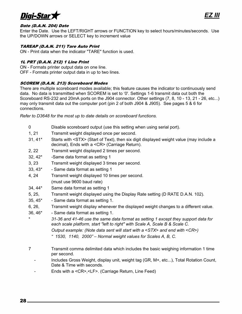
Date (D.A.N. 204) Date
Enter the Date. Use the LEFT/RIGHT arrows or FUNCTION key to select hours/minutes/seconds. Use the UP/DOWN arrows or SELECT key to increment value TAREAP (D.A.N. 211) Tare Auto Print
ON - Print data when the indicator "TARE" function is used. 1L PRT (D.A.N. 212) 1 Line Print
ON - Formats printer output data on one line. OFF - Formats printer output data in up to two lines.
SCOREM (D.A.N. 213) Scoreboard Modes
There are multiple scoreboard modes available; this feature causes the indicator to continuously send data. No data is transmitted when SCOREM is set to ‘0'. Settings 1-6 transmit data out both the Scoreboard RS-232 and 20mA ports on the J904 connector. Other settings (7, 8, 10 - 13, 21 - 26, etc...) may only transmit data out the computer port (pin 2 of both J904 & J905). See pages 5 & 6 for connections.
Refer to D3648 for the most up to date details on scoreboard functions.
0 Disable scoreboard output (use this setting when using serial port).
1, 21 Transmit weight displayed once per second.
31, 41* Starts with <STX> (Start of Text), then six digit displayed weight value (may include a decimal), Ends with a <CR> (Carriage Return).
2, 22 Transmit weight displayed 2 times per second.
32, 42* -Same data format as setting 1
3, 23 Transmit weight displayed 3 times per second.
33, 43* - Same data format as setting 1
4, 24 Transmit weight displayed 10 times per second.
(must use 9600 baud rate)
34, 44* Same data format as setting 1
5, 25, Transmit weight displayed using the Display Rate setting (D RATE D.A.N. 102).
35, 45* - Same data format as setting 1.
6, 26, Transmit weight display whenever the displayed weight changes to a different value.
36, 46* - Same data format as setting 1.
* 31-36 and 41-46 use the same data format as setting 1 except they support data for each scale platform, start "left to right" with Scale A, Scale B & Scale C.
Output example: (Note data sent will start with a <STX> and end with <CR>)
“ 1530, 1140, 2000” – Normal weight values for Scales A, B, C.
7 Transmit comma delimited data which includes the basic weighing information 1 time per second.
- Includes Gross Weight, display unit, weight tag (GR, M+, etc...), Total Rotation Count, Date & Time with seconds.
- Ends with a <CR>,<LF>. (Carriage Return, Line Feed)

Technical Manual
D3739 29
8 Transmit comma delimited data which includes the basic weighing information once every 5 seconds. Same data format as setting 7.
9 Selection #9 is reserved.
10 Transmit comma delimited data which includes the EID Tag Reader information once every 2 seconds.
- Includes Gross Weight, display unit, weight tag (GR, M+, etc...), Date & Time.
- Ends with a <CR>,<LF>. (Carriage Return, Line Feed).
For more details on data field format see “Send All EID Records Command” response
sw550/sw2600 format.
NOTES: When using SCOREM = 1, 2, 3, 4, 5, 6 and 9 be sure to set LSTORE = OFF, TAREAP = OFF and APRINT = OFF to avoid corrupted data when transmitting and printing data.
When using SCOREM = 7, 8 and 10, print data will not be corrupted by scoreboard data.
11 Transmit comma delimited data which includes the "serial gross weight" 2 times per second.
See service Bulletin #31 for additional information about the “Serial Gross Weight”.
The serial gross weight data will be sent at 9600 Baud, 1 start bit, 7 data bits, 1 EVEN parity bit and 1 stop bit on pin 2 (COM #1 Tx line) of a J904 or J905 Serial / Printer connector.
Please Note: This setting may not be available if a radio is installed in the indicator for communications to a Cab Control or Datalink system.
- Starts with <STX> (Start of Text).
- Six digit Serial Gross Weight “whole number” value (ie.1000 not 100.0).
- "LB" or "KG" unit of measure.
- Space character.
- "SG" to identify Serial Gross weight.
- The <ETX> (End of Text) control character.
- Checksum Character (C) value that includes all bytes starting after the <STX> up through, but not including the <ETX>. The Check Sum calculation is found at the end of this section.
- Ends with a <CR> (Carriage Return).
12 Transmit comma delimited data which includes the "displayed gross weight" 10 times per second.
- Same data format as setting 11
When using SCOREM 11, 12, The value is calculated using a "serial zero/balance point" (ZEROUT D.A.N. 219) and may not match the weight displayed on the scale. The serial gross weight is not affected when the operator performs a normal zero/balance. The serial gross weight value will always be gross and does not change when the operator performs a normal zero/balance or selects the Net or Load/Unload weight to be displayed.
Settings 11 and 12 are not available if a radio is installed in the indicator for communications to a Cab Control or Datalink system.
EZ III
30
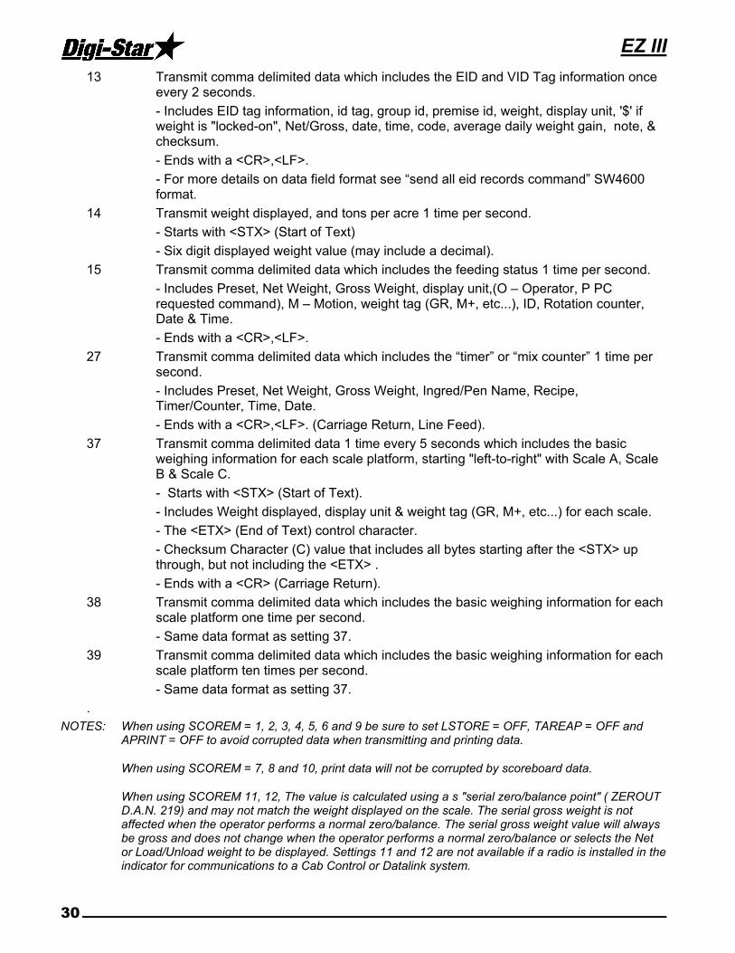
13 Transmit comma delimited data which includes the EID and VID Tag information once every 2 seconds.
- Includes EID tag information, id tag, group id, premise id, weight, display unit, '$' if weight is "locked-on", Net/Gross, date, time, code, average daily weight gain, note, & checksum.
- Ends with a <CR>,<LF>.
- For more details on data field format see “send all eid records command” SW4600 format.
14 Transmit weight displayed, and tons per acre 1 time per second.
- Starts with <STX> (Start of Text)
- Six digit displayed weight value (may include a decimal).
15 Transmit comma delimited data which includes the feeding status 1 time per second.
- Includes Preset, Net Weight, Gross Weight, display unit,(O – Operator, P PC requested command), M – Motion, weight tag (GR, M+, etc...), ID, Rotation counter, Date & Time.
- Ends with a <CR>,<LF>.
27 Transmit comma delimited data which includes the “timer” or “mix counter” 1 time per second.
- Includes Preset, Net Weight, Gross Weight, Ingred/Pen Name, Recipe, Timer/Counter, Time, Date.
- Ends with a <CR>,<LF>. (Carriage Return, Line Feed).
37 Transmit comma delimited data 1 time every 5 seconds which includes the basic weighing information for each scale platform, starting "left-to-right" with Scale A, Scale B & Scale C.
- Starts with <STX> (Start of Text).
- Includes Weight displayed, display unit & weight tag (GR, M+, etc...) for each scale.
- The <ETX> (End of Text) control character.
- Checksum Character (C) value that includes all bytes starting after the <STX> up through, but not including the <ETX> .
- Ends with a <CR> (Carriage Return).
38 Transmit comma delimited data which includes the basic weighing information for each scale platform one time per second.
- Same data format as setting 37.
39 Transmit comma delimited data which includes the basic weighing information for each scale platform ten times per second.
- Same data format as setting 37.
.
NOTES: When using SCOREM = 1, 2, 3, 4, 5, 6 and 9 be sure to set LSTORE = OFF, TAREAP = OFF and APRINT = OFF to avoid corrupted data when transmitting and printing data.
When using SCOREM = 7, 8 and 10, print data will not be corrupted by scoreboard data.
When using SCOREM 11, 12, The value is calculated using a s "serial zero/balance point" ( ZEROUT D.A.N. 219) and may not match the weight displayed on the scale. The serial gross weight is not affected when the operator performs a normal zero/balance. The serial gross weight value will always be gross and does not change when the operator performs a normal zero/balance or selects the Net or Load/Unload weight to be displayed. Settings 11 and 12 are not available if a radio is installed in the indicator for communications to a Cab Control or Datalink system.

Technical Manual
D3739 31
APRINT (D.A.N. 214) Auto Print
ON - Pressing the following keys will automatically print weight values. TARE, TR, ID, LOAD/UNLOAD, NET/GROSS, and PRINT
Auto Print prints all transactions. This feature also works with wireless transmitters.
COM IN (D.A.N. 215) Computer Input Mode
DOWNLD Data Downloader, 1200 Baud EZ CMD Original EZI Commands, 1200 Baud EZ2CMD EZ II Commands, 9600 Baud
PRTFMT (D.A.N. 216) Print Format
Many data output formats are available. See the end of this manual or D3648 for more details.
MEDIA (D.A.N. 217) Media Type
This menu allows the user to select the data storage device to be used with the indicator. DDL Data Downloader DATAKY DataKey SER PC Allows both DataKey and serial PC to be used for batching data storage on the indicator. USB USB Flash/Thumb drive SERIAL USB Allows both USB and serial PC to be used for batching data storage on the indicator. REMOTE (D.A.N. 218) Remote
ON - The indicator sends display data to the Cab Control Remote. OFF - The indicator does not send display data.
ZEROUT (D.A.N. 219) Zero Output
Use this selection to Zero / Balance the weight for the Continuous Serial Gross Weight - Scoreboard Mode setting #11 (described above). C1 DLY (D.A.N. 221) COM 1 Delay
Com 1 Delay chooses the number of seconds the printer will delay before advancing to the next print line. Select one of the following:
OFF No delay 1 1 Second
.10 1/10 of a second 2 2 Seconds
.25 1/4 of a second 3 3 Seconds
.50 1/2 of a second 4 4 Seconds
.75 3/4 of a second 5 5 seconds
C2 DLY (D.A.N. 222) COM 2 Delay
Com 2 Delay chooses the number of seconds the printer connected to the 2nd serial port will delay before advancing to the next print line. Selections are same as for C1 DLY.

EZ III
32
PRTACC (D.A.N. 223) Print Accumulation
This feature is designed to automatically keep a running total of the weights printed. It is similar to a Memory Plus (M+) feature, but it is done automatically each time the weight is printed. Another difference from the M+ feature is that the weight value is always recorded as a positive weight. For example, if the Print Accumulation contained a value of 5000 and -1500 was printed, the new Print Accumulation value would be 6500 (change the -1500 to +1500 and then add it to 5000 = 6500). The Print Accumulation can be viewed by entering Menu 2 of the Long Form Setup. Select either the “PRTAC1” or “PRTAC2” print formats to have the Print Accumulation sent to a printer. To clear the Print Accumulation value, press the Zero key while the PRTACC value is displayed in the Long Form. The Print Accumulation value is stored in non-volatile memory and will be retained even after the scale is turned off. Also accessible to view or clear on seed tender indicators after saving FIELD information.
RMC EN (D.A.N 224) RMT CC START STOP ENABLE
ON – Enables Cab Control start/stop control.
RECSIZ (D.A.N. 225) Record Size Allows the user to define how many printed lines the scale will consider one record. The selection “AUTO” will automatically select how many lines are in a record, the remaining selections (1 - 9) define the selection’s number as how many lines are in a record. This menu item was created to work with the buffer series commands.
SCL NO (D.A.N. 231) Wireless Scale Number
This number is used to identify this specific indicator to the Cab Control unit and the Datalink software. Up to 24 different numbers can be selected. RMDISP (D.A.N. 234) Select Remote Display Type
EZ2 For most Remote Displays, including RD1000 or RD2000 EZ3MUX For First Generation RD2400 Remote Display COG For RD2500V Remote Display
BARGRP (D.A.N. 236) Bar Graph Mode
Select how the bar graph works on the RD4000. The bar graph can be set to:
0 = OFF. 1 = Display from “left to right” for Presets and Timer/Counter only. 2 = Display from “left to right” for Presets, Timer/Counter & Gross Full Scale Weight. 3 = Display from “right to left” for Presets and Timer/Counter only. 4 = Display from “right to left” for Presets, Timer/Counter & Gross Full Scale Weight.
BAR WT (D.A.N. 237) Bar Graph Weight
Enter the Gross Full Scale Weight to activate all LED’s of the bar graph on the RD4000 remote. This is used with Bar Graph Modes 2 and 4. If set to a weight value of 12,000, approximately half of the bar graph will be lit when the gross weight displayed is 6,000. BUFFER (D.A.N. 238) Print Buffer
ON - Data sent to the printer port is also stored in the scale’s non-volatile “record” memory. When this setting is accessed in the Long Form, the percentage of the available record memory is displayed.

Technical Manual
D3739 33
PBLINE (D.A.N. 239) Print buffer scroll Lines
Adjusts how many lines of the internal Print Buffer memory will be scrolled for each press of the Up or Down Arrow key. A setting of 3 lines (which should be used for the Print Format PRTAC5) will scroll the display by one full record for each press of the Up or Down Arrow key. LOW WT (D.A.N. 241) Analog Low Weight
For Units with Analog Output The "LOW WT "setting allows the user to enter the weight value that equals low output limit (4mA or 0V) for the analog output. The “LOW WT” value must be smaller than the “HIGH WT” value. HIGHWT (D.A.N. 242) Analog High Weight
For Units with Analog Output The "HIGHWT "setting allows the user to enter the weight value that equals the high output limit (20mA or 5V) for the analog output. The “HIGH WT” value must be larger than the “LOW WT” value.
ANAOUT (D.A.N. 243) Analog Output Option
Analog Output is an optional feature installed on the option board. Jumpers on the option board must match the setting in this menu.
0-5VDC Analog Output from 0 to 5 Volts DC. 4-20MA Analog Output from 4 to 20mA without error detection 0-20MA Analog Output from 0 to 20mA (error indicated with output below 4mA)
Note: Internal jumpers must also be moved when this selection is changed. Please refer to the Analog Output Manual (D3708) for further details. -ANALG (D.A.N 244) Negative Analog Output
Allows the analog output 4-20mA setting to represent weight values less than the Analog Low Weight selection (LOW WT) in Menu 2. This setting allows the signal to represent weights as low as 3mA. This is useful to show weight values below the Zero/Balance point when the Analog Low Weight selection (LOW WT) is set to 0.
ZEROFP (D.AN. 249) Front Panel Zerout
All Models with Analog Out: Zero Serial Gross Weight using Front Panel (ZEROFP - D.A.N. 249) The Zero Serial Gross Weight using Front Panel selection (ZEROFP) in Menu 2 can be turned “On” to allow the Serial Gross Weight to be Zero/Balanced using Front Panel [Zero] key rather than the Zero Output selection (ZEROUT) in Menu 2. This is when the Analog Output needs to match the weight shown to the operator on the indicator display.
RMTERM (D.A.N. 251) Remote Terminal
ON - Allows external devices to use the Cab Control Communication on a serial “wired” interface. ISO WT (D.A.N. 252) Isobus Weight
The Send ISO Weight selection (ISO WT) in Menu 2 can be set to periodically output the most current Gross, Net & Load/Unload weights to external devices connected to the Serial Port. Settings start at "OFF" (no transmissions) and increase in 0.1 second increments up to 2.0 seconds. OPSTAT (D.A.N. 253) Operating Status
The Continuous Operating Status setting in Menu 2 will cause one or more data packets to be transmitted from the scale continuously.
Refer to the EZII Escape Computer Command Set document D3648 for more information.

EZ III
34
RMPORT (D.A.N. 254) Remote Terminal Port
The Serial Remote Terminal Port selection in Menu 2 allows external devices using Serial Remote Terminal or ISO Weights to be on either COM1(1) or COM2(2). RMNOPR (D.A.N. 255) DISABLE RMPORT RESPONSE
ON – Disable sending ‘print’ type response to commands received.
ISOADR (D.A.N. 256) ISOBUS BASE ADDRESS
Allow the ISOBUS Scale Link to claim a specific address. Upon being commanded to change addresses, the ISOBUS Scale Link stores the new address, ends the use of the current address, and performs a new address claim starting at the new address. The default address is typically 144 (0x90). ISO VT (D.A.N. 257) DISABLE ISOBUS VT MESSAGE
Allows the scales user interface to display on a Virtual Terminal. Default value for Scale Link ISOBUS scales is ON.
Note: Disabling the Virtual Terminal communications does not affect the settings for ISO WT (D.A.N. 252) when broadcasting weight values to ISOBUS.
PRNT-2 (D.A.N 261) PRINT ON PIN 2
Allows the printer output on the J905 Printer connector to be transmitted on pin 2 rather than pin 4. This is helpful when using printer cables already wired for pin 2. Print data is normally transmitted at 1200 BAUD from the indicator. To change the BAUD rate from 1200 to 9600 (as needed by some printers), change the COM IN (D.A.N. 215) setting in Menu 2 from DDL or EZ CMD to EZ2CMD. Please note: The indicator will RESET itself after changing this Menu setting. SERIAL PORT PARITY AND BAUD RATE SETTINGS
C1-1PA (D.A.N. 271) COM1-1 Parity
C1-2PA (D.A.N. 272) COM1-2 Parity
C1-3PA (D.A.N 273) COM1-3 Parity
C2 PA (D.A.N. 274) COM2 Parity
Allows the parity bits to be programmed for COM port 1-1 (Computer/Printer Port on J904 pin 2), COM port 1-2 (Scoreboard Port on J904 pin 4) and COM 2 (Printer Port on J905 pin 4). The options for parity programming are: 7E1, 8N1, and AUTO. The auto setting sets the parity to the default setting of 7E1.
C1-1BD (D.A.N. 275) COM1-1 baud rate
C1-2BD (D.A.N. 276) COM1-2 baud rate
C1-3BD (D.A.N. 277) COM1-3 baud rate
C2 BD (D.A.N. 278) COM2 baud rate
Allows the baud rate to be programmed for COM1-1, COM1-2, and COM2. The options for baud rate programming are: 1200, 2400, 4800, 9600, and AUTO. The auto setting sets the baud rate to the default setting of COM IN (D.A.N. 215). These settings will not appear in the Menu on models without the Serial Print option, and may not be available on the NT460, units with internal radios, or Datalink. COM 1-1 and 1-2 settings must be the same when using COM 1 to receive computer data. EST WT (D.A.N. 299) Estimate Weight
This feature sets the gross weight to a new value. Use this feature when the scale has been accidentally Zero Balanced or if a scale indicator is replaced and the gross weight on the scale is known.

Technical Manual
D3739 35
MENU 3
COUNT (D.A.N. 301) Display Count
Indicator displays count in increments of 0.01, 0.02, 0.05, 0.1, 0.2, 0.5, 1, 2, 5, 10, 20, 50, and 100. If the count is set too small, the readings will be unstable and the indicator will not be accurate. Display count should be equal to or greater than 1/4000 of the capacity. This command changes the Setup number. See also (D.A.N. 871) ARANGE (D.A.N. 302) Auto Range
ON Scale increases display count size for weights over 300 and again at 600 lbs/kgs. OFF Display counts are set and do not vary Example: 0 to 300 lbs (1 lb Increment), 300 to 600lbs. (2 lbs Increments), 600 and up (5 lbs. Increments). LB-KG (D.A.N. 303) Display Unit
Select desired weight unit to be displayed. When changing weight unit using the long form, the
calibration is adjusted so the scale displays accurately in the new display unit. CAP (D.A.N. 304) Scale Capacity
Enter MAXIMUM weight measurable on scale. This will change the last 3 digits in the setup number. See also (D.A.N. 871). WMA1-1 (D.A.N. 305) Weigh Method 1 Adjust 1
Choose a value from 2 – 100 (factory setting = 10). This setting is the main “filter” setting for the weigh method. A small filter number such as 2 or 4, causes the scale to respond quickly to weight changes, but may cause the display to appear “jumpy.” A large filter number, such as 32 or 64, causes the scale to be more stable, but the scale is “slow” to respond to weight changes.
WMA1-2 (D.A.N. 306) Weigh Method 1 Adjust 2
Choose a value from 0 – 100 (factory setting = 4). When this adjustment is set to a value other than 0, it activates a “Quick Response” feature. This allows the scale to quickly respond to large weight changes.
WMA1-3 (D.A.N. 307) Weigh Method 1 Adjust 3
Set the “Quick Response Weight” for Weigh Method #1 (General). If weight added to the scale is greater than the amount set here, the “Quick Response Average Number” setting of WM1-A2 is used as the filter number. The default is 10% of the scale’s capacity. For example, if this value is set to 3000, the weight must change more than 3000 lbs before Weigh Method #1 will use the “Quick Response Average Number” set in WM1-A2. Once close to the actual weight, Weigh Method #1 uses the filter number set in WM1-A1.
WMA2-1 (D.A.N. 311) Weigh Method 2 Adjust 1
Choose a value from 2 – 100 (factory setting = 30). This adjustment is the “Maximum Average Number” setting for Weigh Method #2 (Slow). This number determines how many of the previous weight samples to average. A small average number such as 2 or 4 causes the scale to respond quickly to weight but may cause the display to appear “jumpy.” A large filter number, such as 32 or 64, causes the scale to be more stable, but the scale is “slow” to respond to weight changes.
EZ III
36
WMA2-3 (D.A.N. 312) Weigh Method 2 Adjust 2
Choose a value from 0 – 100 (factory setting = 10). This adjustment is the “Quick Response Average Number” setting for Weigh Method #2 (Slow). If adjustment 2 is set to a value other than 0, it activates the “Quick Response” feature. This allows the scale to quickly respond to large weight changes. WMA2-3 (D.A.N. 313) Weigh Method 2 Adjust 3
Adjustment 3 sets the “Quick Response Weight” for Weigh Method #2 (Slow). If weight added to the scale is greater than this amount, the “Quick Response Average Number” setting of WM2-A2 is used as the filter number. The default is 10% of the scale’s capacity. For example, if this value is set to 3000, the weight must change more than 3000 lbs before Weigh Method #2 will use the “Quick Response Average Number” set in WM2- A2. Once close to the actual weight, Weigh Method #2 increases the “Quick Response Average Number” on each conversion until the number of averages equals the Maximum Average Number set in WM2-A1.
TC1300 (D.A.N. 321) Mimic Tyrel TC 1300
This feature causes the indicator to weigh differently while batching. The ingredient or pen preset weight display includes all weight changes that have occurred since the last ingredient or pen weight was logged. The Tare key can be used to clear any weight displayed prior to loading or unloading. When set to OFF, the ingredient or pen preset weight displayed only shows the weight-change from when the preset was started. Indicator records preset weights like a Tyrel TCX1300. 10K TA (D.A.N. 322) Application Rate 10km/h
If ON, the 10 km/h Application Rate (10K TA) in Menu 3 works with the Scoreboard Mode (SCOREM) setting in Menu 2 to output the application rate as if the operator was unloading at 10 kilometers per hour (km/h). Since the actual application rate in Tons/Acre (or Tonnes/Hectare) is inversely proportional to the spreader speed, this allows the “actual application rate” to be calculated using the “actual spreader speed”.
A UNIT (D.A.N. 323) Application Units
NT460 application. Set measurement units to "ENGLSH" (Tons/Acre, Feet and Miles/Hour), or "METRIC" (Tonnes/Hectare, Meter and Kilometers/Hour). RATE (D.A.N. 324) Application Rate
To quickly enter the desired application rate in Tons per Acre (or Tonnes / Hectare), press the [Select] key until "RATE" is displayed, then press the [Function] key. The value is displayed with a decimal point, so 5 Tons/Acre is entered as "50" which is displayed as "5.0". Application Rate can also be accessed in Menu 3 of the Long Form Menu.
Note: The Application Measurement Unit (A UNIT) in Menu 3 will determine if the value is entered in either English (Short Tons/Acre & Spread width in Feet) or Metric (Tonnes/Hectare & Spread width in Meters).
WIDTH (D.A.N. 325) Application Spread Width
To quickly enter the Application Spread Width, press the [Select] key until "WIDTH" is displayed, then press the [Function] key. The value is displayed with a decimal point, so 40 feet is entered as "400" which is displayed as "40.0". Application Spread Width can also be accessed in Menu 3 of the Long Form Menu.
Note: The Application Measurement Unit (A UNIT) in Menu 3 will determine if the value is entered in either English (Short Tons/Acre & Spread width in Feet) or Metric (Tonnes/Hectare & Spread width in Meters).

Technical Manual
D3739 37
GPSSTR (D.A.N. 326) GPS Storage Rate
Set for how often the GPS coordinates are stored while unloading. 0 = "OFF" (no storage), 1 = every second, 2 = every 2 seconds, 3 = every 3 seconds, up to once every 20 seconds.
Note: The NT460 has enough memory to store approximately 195 loads (32.5 hours) of GPS application rate information when GPSSTR = 5 seconds.
ACRES (D.A.N. 327) Total Acres
Shows a running total of the acres spread for a particular field. Press ZERO to erase the accumulated value for the current field, or FIELD to erase the values for all the fields. ARATE1 (D.A.N. 331) Application Rate Estimate
Set for number of weight samples to be used for the application rate estimate. A small number like 2 or 4 causes the estimate to respond more quickly, but may cause the T/A display to appear “jumpy”. A large value, such as 8 will smooth out the T/A display, but with a slower response. The value can be set between 2 and 10 samples. ARATE2 (D.A.N. 332) Application Rate Average
Set for number of application rate samples to be averaged to calculate the final application rate estimate. A smaller number decreases the response time, but may cause the display to appear “jumpy”. The value can be set between 1 and 5 samples. ARATE3 (D.A.N. 333) Application Rate Window
Set for a range or window around the desired application rate value (RATE - D.A.N. 323). 0 = "OFF", 1 = RATE +/- RATE, 2 = RATE +/- ½ RATE, up to 9 = RATE +/- 1/9 RATE. When the actual application rate estimate is outside the window, the number of weight samples used for the estimate is determined from the minimum samples setting (ARATE4 - D.A.N. 334). When the actual application rate is within the window, the number of weight samples used for the estimate is determined from the Application Rate Estimate value (ARATE1 - D.A.N. 331) ARATE4 (D.A.N. 334) Application Minimum Samples Set for the minimum number of weight samples used to calculate the application rate estimate, when the estimate is outside of the window determined from (ARATE3 - D.A.N. 333). If the Application Rate
Window (ARATE3 - D.A.N. 333) is set to 0=”OFF”, the minimum samples value is not used for the estimate. The value can be set between 2 and 10. AWEQUL (D.A.N. 335) Application Rate Equal Weights Set the number of equal weight samples used to determine if the displayed application rate estimate should be zeroed. If the last AWEQUL weight samples are determined to be within 1 display count of the latest weight sample, the application rate estimate is zeroed. 0=”OFF”, 1 = previous sample, 2 = previous 2 samples, up to 8 = previous 8 samples. This setting should be increased for low application rates. The Display Count (COUNT - D.A.N. 301) should be set to 10. ARATE5 (D.A.N. 336) Application Rate Speed Adjust
Set the response of the application rate estimate calculation when spreader unloading ‘starts’. When set to ‘SLOW’ the settings for ARATE1 - ARATE4 will always be used to determine the application rate estimate. When set to ‘FAST’, a quicker response will be observed when the GPS spreader speed increases above 1kmh, or the number of equal weight samples satisfies the Application Rate Equal Weights value (AWEQUL) condition over the last 3 seconds. When in ‘fast’ mode, the number of samples used for the application rate estimate, and application rate average, are set equal to minimum values of 2 and 1, and increase towards the values set by ARATE1 - ARATE4.

EZ III
38
A L/UL (D.A.N. 337) APP RATE LOAD / UNLOAD
This software supports calculating either the “crop yield” (LOAD) or “application rate” (UNLOAD) in Tons per Acre (or Tonnes / Hectare) depending upon whether weight is being added or removed from the vehicle. ABCDSP (D.A.N. 341) A,B,C Display Format
Allows the weight for the ABC scales to be displayed individually as three "SINGLE" scales (as on previous ABC scale systems), or always together showing the "TOTAL" (A+B+C) or "COMBIN"ed which also displays the A+B+C weight. The "COMBIN"ed setting also causes the Balance, Tare, Net and Gross function to be performed to ALL 3 scales at the same time. Please note: Each input (A,B,C) has their own Setup and Calibration numbers in all settings.
MENU 4
P MTHD & P-ALM (D.A.N. 401) Pre-Alarm
Select WEIGHT OR PERCNT Enter a value to activate an early warning that scale is reaching the preset weight.
RM INP (D.A.N. 402) Remote Input
PRESET The Remote Input on the power cord (and the input from the TR option) will re-enter the last preset value entered.
TARE The Remote Input performs the TARE function and “zeroes” the display. MIXCTR Enables the “Rotation Counter” on equipped indicators. This disables “PRESET’ and
‘TARE” Feature. On the EZ3200/3400, the options are the same. However, if a recipe is loaded, the TARE function causes the Remote Input to advance ingredients. If no recipes are loaded, the Remote Input performs a TARE.
SEEDTD Used to advance Seed Tender scale to next seed dispense operation; re-enters preset. SWITCH Select Remote Input Setup setting ‘SWITCH‘ to display a message for an ‘OPEN’ or
‘CLOSED’ condition on the remote input line of the power cord. TRKEY1 Used in conjunction with TRKEY1 (D.A.N. 121). When selected TR (Transmitter –
Receiver kit) can be used for the following functions: TARE, START/STOP, PRINT, LOAD, HOLD, NET/GROSS, M+, RECHECK, INGRED and RE- ENTER PRESET.
AL OUT (D.A.N. 403) Pre-Alarm
TR The Alarm Output allows the alarm capabilities of the preset alarm to be controlled by the TR keys. The Front Panel Alarm light and the relay output is ON (+12V) when a TR command has been accepted by the scale.
PRESET Causes the alarm capabilities to be controlled by the preset alarm. SWITCH Select Alarm Output setting ‘SWITCH‘ to illuminate the lamp for an ‘OPEN’ or ‘CLOSED’
condition on the remote input line of the power cord.
BUZZER (D.A.N. 404) Alarm Buzzer
Can be set to OFF, 20%, 40%, 60%, 80% or ON. For example, when 40% is selected, the buzzer that would normally be on for a 2 second alarm would only be active for about ½ second. PRETAR (D.A.N. 405) Pre Tare
The PRETAR feature allows the tare weight of a container to be entered using the numeric keypad.

Technical Manual
D3739 39
RELAY (D.A.N. 406) +12VDC Alarm Output
PRESET Activate with the preset alarm; pulsing on & off. SETPNT Activate when the gross weight exceeds the Gross Set Point Value (SETPNT). OFF Relay does not turn on SEEDTD Activate 12V during seed dispense operation to turn on seed tender conveyor/ auger
U ALRM (D.A.N 407) Unload Alarm
Adjust the horn that is activated while unloading. The alarm sounds each time UNLOAD is displayed. Set to 1 for the shortest alarm. Set to 2 and 3 for longer alarms, and 4 for the longest alarm. The alarm BUZZER setting (D.A.N. 404) has priority and should be set to ON in order for the Unload Alarm feature to operate correctly.
RI MSG (D.A.N 411) REMOTE SWITCH MESSAGE
Used to edit the message that is displayed for an ‘OPEN’ or ‘CLOSED’ condition on the remote input line of the power cord. The default message is ‘OPEN ’
RISTAT (D.A.N 412) REMOTE SWITCH STATE
Determines if the Remote Switch Message or Alarm Output lamp is displayed/illuminated for an ‘OPEN’ or ‘CLOSED’ condition on the remote input line of the power cord. The default setting is ‘CLOSED’.
RITIME (D.A.N. 413) REMOTE SWITCH MSG
Used to set how often the Remote Switch Message is displayed for an ‘OPEN’ or ‘CLOSED’ condition on the remote input line of the power cord. For the default value of 2, the message is displayed every 2 seconds. The maximum setting is 9 seconds.
TMRCTR (D.A.N. 421) Timer Counter
The Mix Timer feature displays mixer auger revolutions based on input pulses from a revolution-sensing device and an adjustable drive ratio that indicates how many pulses equal one (1) revolution.
DRATIO (D.A.N. 422) Drive Ratio
The Drive Ratio is a number that tells the indicator how many pulses equal 1 mixer revolution. The drive ratio can be any number between 0.01 and 999.99. SETPNT (D.A.N. 423) +12VDC Alarm Output
For EZ 3400, EZ 3600 and EZ 4600 this feature allows the operator to set a Gross weight in the Long Form that will activate the +12VDC Alarm Output on the power cord. The Set Point weight can range from 0-999999 and uses the Gross weight shown for the Zero Output feature (ZEROUT D.A.N. 219). SETCHG (D.A.N.424) Set Point Weight Change
For EZ 3400, EZ 3600 and EZ 4600 this setting is used with Gross Set Point. This is the “weight change” required to turn off the +12VDC Alarm Output after it has been activated. This weight must be lower than the weight entered for SETPNT (from 0-999999). Once the weight on the scale is below the Gross Set Point by the “weight change” amount, the +12V Alarm Output will change back to the original output (prior to reaching the gross set point). This setting prevents the +12VDC Alarm Output from repeatedly turning on and off when mixing around the actual SETPNT weight. SETDEL (D.A.N. 425) Set Point Delay Time
For EZ3400, EZ3600 and EZ4600 models only. This setting is used with Gross Set Point. This “delay time” must expire before the +12VDC Alarm Output can turn on or off. The selection ranges from 0 to 10 seconds. This setting prevents the 12VDC Alarm Output from repeatedly turning on and off when mixing around the actual SETPNT weight.

EZ III
40
SETOUT (D.A.N. 426) Gross Set Point Output
For EZ3400, EZ3600 and EZ4600 models only.
Gross Set Point determines when the +12VDC Alarm Output becomes active. OVER The relay will turn on when the weight is equal to or exceeds the Gross Set Point weight. UNDER The relay will turn on when the weight is equal to or below the Gross Set Point weight.
PROGRAM (D.A.N. 439) Program Recipe
When set to “SCALE”, recipes can be programmed at the indicator, similar to the EZ3200/V and EZ3400/V. When set to “ PC ”, all recipes are programmed on a PC and transferred to the indicator using either the Datakey, USB, or Datalink.
Please refer to the Operator Manual’s for further details about this option.
RECKEY (D.A.N. 438) RECIPE KEYS
Keys on the indicator will be disabled while using a recipe to prevent errors by the operator pressing the wrong key. Disabled Keys: Left Cursor, Right Cursor, Zero, On, Tare, Net/Gross, Recipe, Pens, 1,2, 3, 4, 5, 6, 7, 8, 9, 0, ID, Select and Function. Active Keys: Hold, Timer, Print, Enter, Up Cursor, Down Cursor, Clear, Help
E MTHD (D.A.N. 441) Entry Method
Select the entry method to use when programming recipes. Select one of the following: 1 – Amount per animal 2 – Percent per load 3 – Amount per load TOLER (D.A.N. 442) T MTHD & Tolerance
PERCNT OFF, .5, 1, 2, 3, 4, 5, 7, 10 WEIGHT Enter numerical weight value When the auto advance feature is activated, the indicator automatically prints and advances to the next ingredient or pen once the tolerance and delay time DELAY (D.A.N. 443) requirements have been met. Tolerance and delay time requirements are explained below. The Tolerance feature is a "tolerance window" for the preset ingredient or pen during batching. For example, if the tolerance is set to 5% and the preset is 1000 lbs., the "tolerance window" is 50lbs. The scale is in the "tolerance window" when the display is between 50 and -50 lbs. The auto-advance function activates the Delay Time while the weight is in the tolerance window. The Delay Time allows the operator to slightly "under or over shoot" and ingredient or pen amount and still automatically advance to the next ingredient or pen. The auto-advance Delay Timer resets every time the weight moves out of the tolerance window. TOLER on Seed Tender Scales; long form setting of SEEDTD Calculating Auger Tolerance; set to WEIGHT then enter value. Auger tolerance is the weight offset of seed remaining in the seed tender auger or conveyor while filling the planter. This value is set to adjust for the delay of the auger to stop movement of seed sliding out of the seed chute. This value may need to change based on seed chute size, extended seed chute length, seed type, and seed weight. Set the “TOLER” value for the expected use of the seed tender.

Technical Manual
D3739 41
DELAY (D.A.N. 443) Ingredient Advance Delay
DELAY controls the number of seconds to wait before auto-advancing to the next ingredient of a recipe. Enter value in seconds, a value of 0 sets manual advance. INGRNM (D.A.N. 444) Ingredient Names
Used by EZ3400 indicators ON Attach ingredient/pen names to items in the ingredient table. OFF Uses numeric list. (ING-01…) ACCUM (D.A.N. 445) Accumulator
ON Enables recipe accumulation during batching.
USERID (D.A.N. 446) Force User ID
ON Operator MUST enter User ID before using the scale.
MSTORE (D.A.N. 447) Media Storage
QSTART For Datakey/USB use, data is automatically uploaded/ downloaded when media is installed.
MANUAL For Datakey/ DDL use. Media does not need to stay installed into indicator. Transfer is done manually by use of SELECT and FUNCTION keys.
AUTO For Datakey/ DDL use. Media stays installed into indicator and data is stored after each ingredient/pen is completed.
RESIZE (D.A.N. 448) Resize Recipe
ON Allows the user to change the recipe size by changing the amount to feed or the number of animals for each pen.
INGSIZ (D.A.N. 449) Ingredient Re-Sizing
1 ING - First Ingredient Resize This feature will resize the entire recipe if the first ingredient’s loaded weight is outside of the Tolerance (TOLER- D.A.N. 442) window of the preset. Resizing changes the preset of each ingredient to mimic the ratio loaded in the first ingredient and keep the nutritional value of the recipe the same. 1+2ING - First Plus Next Ingredient Resize This feature will resize the second or next ingredient if the first ingredient loaded weight is outside of the Tolerance (TOLER- D.A.N. 442) window of the preset. Resizing adds (due to under-loading the first ingredient) or subtracts (due to over-loading the first ingredient) the weight error to the weight amount of the second ingredient. This insures that the programmed total of ingredient 1 plus ingredient 2 remains the same. Essentially, this technique uses ingredient 2 to correct for any loading variances of ingredient 1. RECTOT (D.A.N. 451) Recipe Total
EZ3400 option only ON Provides 4 methods of correcting the batch size based on previous batch size errors.
(corrects the load amount by the amount overloaded or under loaded last time. This is Accomplished by changing the weight "Total" displayed at the beginning of the recipe. This feature assist the operator by making the average amount of several feedings equal to the amount programmed for the recipe.
EZ III
42
Programmed { PROG }: This setting always displays the total weight of the recipe as "programmed". The value is shown for recipes programmed in Entry Methods #1 (Amount per Animal) and #2 (Percentage of Load), but shows an actual weight amount if programmed in Entry Method #3 (Amount per Load). Last {LAST}: This setting always displays the total that was "last" used for this recipe. Note: This is how earlier software versions for the EZ 3400 work. Programmed Correction {PRGCOR}: This setting only works for recipes programmed in Entry Method #3 (Amount per Load). It "corrects" the total amount displayed for any under or over feeding that occurred the last time the recipe was used. This helps insure that the amount loaded will average the recipes programmed weight. Last Correction {LSTCOR}: This setting works for all recipes and "corrects" the total amount displayed for the recipe to the "last amount entered on the indicator by the operator", rather than the programmed amount.
SCOOP% (D.A.N. 452) Scoop Percentage
EZ3400 option only Allows the operator to see how much to fill the loader bucket, or how big of a "silage cut" to make by displaying a "scoop percentage" on the LCD. 100% equals 1 bucket load or silage cut (scoop). The "scoop weight" is entered in the ingredient table (one time ) for each ingredient. OVERLCK (D.A.N. 453) Tolerance Over Lock
Prevents the scale from auto-advancing if the amount being loaded or unloaded has exceeded the preset tolerance amount and has caused the scale to display “OVER ”. FDZONE (D.A.N. 454) Feed Zone
Only recipes for the selected feed zone will be visible to the operator. Possible values for the “FDZONE” setting are ALL,1,2,3,4,5,6,7,8, and 9. Selecting “ALL” will enable every recipe in the indicator’s memory to be available for the operator. Selecting any other “FDZONE” setting will allow only recipes for the selected feed zone number to be available to the operator. UNDN (D.A.N. 455) Display Un-done Recipes
ON Indicator will display any recipe that has “undone” feedlines, including recipes that have completed unloading the Pen feedlines, but did not load all of the ingredients. This selection is required to allow the operator to start “Single Ingredient Recipes” using the front panel. OFF Recipes that may have skipped an ingredient, but has unloaded all of the Pen feedlines, will be considered complete and will not be visible to the operator. (For use with Batch-box operation) RECPEN (D.A.N. 456) Display Recipe Pens ON Indicator will display all of the pens to be fed for that recipe. OFF Only the feeding number and recipe name are displayed to the operator when reviewing and selecting recipes.
R TEST (D.A.N. 457) Range Testing
For units with Datalink, The indicator will automatically mark all feedlines sent from DataLink as "Done" to simplify the process of using the indicator to identify the radio communication range of the DataLink system. For normal operation, "R TEST" must be set to OFF.

Technical Manual
D3739 43
AUTPEN (D.A.N. 458) Auto Start
For EZ3600 and EZ4600 models only. ON Indicator will automatically activate the pen list for that feeding once a recipe has been
loaded.
ERASFD (D.A.N. 459) Erase Done Feed-lines
For EZ 3600 and EZ 4600 models only. ON Prevents the internal memory from filling up when (RE-USE D.A.N. 466) is used. Causes
the indicator to automatically erase the "Done" recipes from internal memory after they have been transferred to Datakey, Datalink, or USB drive.
MANPEN (D.A.N. 461) Manual Pen Advance feature
For EZ 3400, EZ 3600 and EZ 4600 models only. Indicator will automatically advance when loading ingredients, but manually advance when making deliveries to pens.
T MTHD / PENTOL (D.A.N. 462) Pen Tolerance
For EZ 3400, EZ 3600 and EZ 4600 models only. This feature forces an operator to press a key on the indicator to confirm that they are intentionally underfeeding a pen and that they want to remove that pen from the recipe or pen list. Otherwise, the pen will remain on the recipe or pen list to be fed later. The pen tolerance can be a percentage (ex. 10%) of the total amount to be fed to that pen or a single weight can be entered (ex. 100 lbs) that will be used for all pens. Set the Tolerance Method (T MTHD) to PERCNT for "percentage of preset weight" or WEIGHT for a "single weight value", then enter either a percentage (ex. 1-99) or an actual weight value (ex. 100). Set Pen Tolerance to 0 to disable this feature. PENWT (D.A.N. 463) Pen Weight
Allows an operator to select how the pen preset weight will be displayed while feeding - Net, Load/Unload (counting down), or Gross modes.
BATNUM (D.A.N. 464) Batch Number Control
For EZ3600 and EZ4600 models only.
EZCTRL The indicator creates the batch number during feeding. The batch number ranges from 300 to 999.
PCCTRL Batch number is determined by PC feeding program.
DBLKEY (D.A.N. 465) Double Key Press Prevention
This feature ignores keys that are accidentally double pressed when advancing to the next ingredient. This includes the Print, Enter, Ingredient-Advance & TR keys. RE-USE (D.A.N. 466) Recipe’s Remain Active
When set to ON, "Loads Mode" recipes will remain active in the indicator so they can be “re-used” for additional loads. The information for each load is also stored with a new, individual batch number that is different from the original batch number sent to the indicator. This allows each “re-used” load to be identified by TMR Tracker or 3rd party software programs. RSTART (D.A.N 467) Recipe Started Weight
The weight amount loaded that determines if a recipe has been started can now be entered at the indicator.

EZ III
44
RENTRY (D.A.N. 468) Recipe Entry
Allows the operator to start a recipe using the batch number. To use this feature, select the setting BATCH# to start recipe’s using the batch number. Select the setting RECIPE to start recipe’s using the recipe name. This feature is only useable with “Loads Mode” recipe formats.
PARTFD (D.A.N 469) Partial Feeding
Allows a portion of a pen’s PRESET weight to be delivered and saved as a separate feedline. The original feedline’s PRESET is updated to remove what was delivered.
PSTART (D.A.N. 471) PEN STARTED WEIGHT
A threshold weight for delivering to pens. Weight must surpass this threshold to count as feeding a pen. Similar to (RSTART D.A.N 467). SPLOAD (D.A.N. 472) Split Load
Automatically re-calculates undone pen presets to completely unload the mixer. This allows for a batch to feed all pens without underfeeding the last pen or having leftover feed in the mixer. No change to the base recipe is required to use this feature. With SPLOAD =OFF, the indicator will function as it has in the past and not automatically re-size any pen. NUMING (D.A.N 473) NUMBER OF INGREDIENTS
For EZ3400 and EZ3400VL models only. Defines the number of ingredients to be used in the Ingredient Name Table INGRNM (D.A.N. 444). Enter number of ingredients to split the table between ingredients and pens. Supports Loads Mode batching where both ingredients and pens can be used in a ration also supports editing existing rations by inserting or deleting feedlines.
STPRST (D.A.N 474) STARTING PRESET WEIGHT
Used for split load weighing along with SPLOAD (D.A.N 472) Used to determine whether to populate the timer/bunk read field (E6) with the starting preset of the feedline at the time of feeding. The starting preset value is returned as part of the completed feedline when the feed records are transferred off the indicator.
MENU 5
UGDOOR (D.A.N. 501) DOOR SETUP
For grain cart door control model only. Enables Grain cart door control feature. UG3SOL (D.A.N. 502) UV GRAIN SOLONOID
For grain cart door control model only. ON Scale uses 3 solenoids. OFF Scale uses 2 solenoids. TRUCK (D.A.N 503) PARTIAL LOAD
For grain cart door control model only. Preset remainder feature keeps track of how much grain is loaded into a specific truck. Feature will signify to operator if truck is empty or partially full and the amount yet to fill truck. Operator selects desired amount to load into truck (partial or full). Operator can override the partial or full amount by typing in desired amount to unload. However, the next time to load the empty truck the original trucks maximum weight capacity will be displayed not the operator's override value. The truck preset or

Technical Manual
D3739 45
maximum weight grain capacity is setup in the grain tracker program for each truck and downloaded to indicator via USB. NOTE: For this feature to work correctly once a grain cart starts filling a truck it can be the only cart to fill the truck for that specific truck load.
S ALRM (D.A.N. 504) SPLIT HOPPER ALARM
For grain cart door control model only. Split hopper capability guides operator to unload specific amount in front and back compartment of selected truck. This setting determines how long to beep the alarm when time to change from front to back truck compartment. Setting can be OFF, 1, 2, 3, or 4 in value. Larger the number the longer the alarm horn beep. NOTE: For the split hopper feature to work correctly once a grain cart starts filling a truck it can be the only cart to fill the truck for that specific truck load. The trucks split hopper value is setup in the grain tracker program for each truck and downloaded to indicator via USB.
SPALRM (D.AN. 505) SPLIT HOPPER PREALARM
For grain cart door control model only. Split hopper pre-alarm value is the amount of weight prior to S ALRM (D.A.N. 504) setting to activate alarm and display "ADVANC" to signify to operator to advance to back compartment of truck during grain cart unloading. Split hopper value is amount of weight to unload from grain cart into the trucks front compartment. The trucks split hopper value is setup in the grain tracker program for each truck and downloaded to indicator via USB.
DOOROW (D.A.N. 506) DOOR OPEN WEIGHT
For grain cart door control model only. Minimum amount of weight that must leave the grain cart before the door is considered to be open. This amount should be larger than fluctuations of weight due to vibrations caused by auger etc… by few hundred pounds.
DDEBUG (D.A.N 507) DOOR DEBUG MODE
For grain cart door control model only. Used to send door cycle debug information out the J905 com1 port. The data is in ASCII text format. SCOREM (D.A.N. 213) should be set to OFF when this feature is enabled. C1 DLY (D.A.N. 221) should be set to OFF when this feature is enabled.
DIAG (D.A.N. 508) DIAGNOSTIC ENABLE
For grain cart door control model only. This feature allows diagnostic screens to be displayed. When this feature is enabled a "DIAG" selection will be available in the SELECT/FUNCTION key menu. Diagnostic screens display information on solenoid status, rpm value, cycle states etc...
DOOROT (D.A.N. 509) DOOR OPEN TIME
For grain cart door control model only. Select the amount of time in seconds required to fully open the grain door from being fully closed. NOTE: See manual for specific details on how to measure.
DOOROP (D.A.N 511) DOOR OPEN PERCENTAGE
For grain cart door control model only. Set the percentage the door will open. Enter percentage amount want door to open. (Ex: 100-full open, 50-half open, 25-quarter open. Setting allows operator to change amount of time to open door without

EZ III
46
changing the one time setup for maximum door open time DOOROT (D.A.N. 509). Operator may want to change how far door is open due to type grain, moisture, new cart operator etc... NOTE: Some tractors cannot handle the load of having the door max open.
DOORCT (D.A.N 512) DOOR CLOSE TIME
For grain cart door control model only. Select the amount of time in seconds required to fully close the grain door when open. NOTE: See manual for specific details on how to measure.
DOORWT (D.A.N. 513) DOOR CLOSE WINDOW
For grain cart door control model only. Set the window for minimum weight change before door will close. Once the door is told to close and the door close travel time has expired the software will monitor the grain carts weight looking for the weight to stabilize. If the grain cart weight does not change +/- this amount of weight for the "door close inside window time" DOORIT (D.A.N. 514) amount of time the door is considered closed.
DOORIT (D.A.N. 514) DOOR INSIDE WINDOW TIME
For grain cart door control model only. Set the maximum time a weight can stay in the weight window before door closes. Enter door close inside window time value in seconds. Once the door is told to close and the door close travel time has expired the software will monitor the grain carts weight looking for the weight to stabilize. If the grain cart weight does not change +/- door close window weight value DOORWT (D.A.N. 513) for this entries amount of time the door is considered closed.
DOORPO (D.A.N. 515) DOOR PREALARM OFFSET
For grain cart door control model only. Set the weight to switch from higher weight to lower weight. Refer to DOORPS (D.A.N 516) description below for details on how this entry is utilized in the door control.
DOORPS (D.A.N 516) DOOR PREALARM SCALER
For grain cart door control model only. Decrease if unloaded results are consistently lower than expected. Set higher if unloaded results are consistently higher than expected. AUGRMX (D.A.N 517) ADAPTIVE AUGER WEIGHT MAX
For grain cart door control model only. Enter maximum allowed weight value for the software to adapt for the weight that will leave the auger after the door has been closed and other inconsistent factors that will affect the unloading accuracy. AUGRWT (D.AN.N 518) LEFTOVER AUGER WEIGHT
For grain cart door control model only. Enter the weight left in the auger after the door has closed that will leave the grain cart. This is only used as a starting point for the door adaptive software. The door adaptive software algorithm will calculate a new door adaptive weight every successful door cycle to enhance unloading accuracy due to inconsistent factors.
DRAWGN (D.A.N. 519) AUGER WEIGHT SCALAR GAIN
For grain cart door control model only. Increase value for faster adaptation, decrease for slower adaptation.

Technical Manual
D3739 47
Enter the door auger weight gain value used in the door adaptive software algorithm. Basically a smaller value will make the calculations adapt faster and a larger value will make calculations adapt slower. Note: A smaller value may cause calculation to adapt quicker but also may not obtain the best accuracy as a larger value.
DOORWC (D.A.N. 521) DOOR WEIGHT CLOSING
For grain cart door control model only. Set the weight for when the grain door should start closing. Enter weight amount so when within amount of target weight time to start checking to see if need to close door. Want this value to be large enough can close door in time to reach target but small enough so when operator is moving cart during unloading we do not use the movement to start closing door when are far away from desired target. RSSCTL (D.A.N. 531) RPM START/STOP CONTROL
Enables AUTOLOG feature (RPM automatic start/stop control feature )
RSSMIN (D.A.N. 532) RPM STOP SPEED
RPM STOP threshold – stop triggered when RPM falls below this value for RSSDPY (D.A.N. 535) amount of time. Set to 20-50% of PTO operating RPMS. Stop is activated using this value
RSSTOL (D.A.N. 533) RPM START TOL
RPM START threshold – start is triggered when RPM exceeds RSSTOL (D.A.N. 533) + RSSMIN
(D.A.N. 532) for RSSTDY (D.A.N. 534) amount of time. Set to 10% of PTO operating RPMS. Start is
activated using this value + RSSMIN (D.A.N. 532).
RSSTDY (D.A.N. 534) RPM DELAY
START delay – start triggered when RPM rises above RSSMIN (D.A.N. 532) + RSSTOL (D.A.N. 533) for this time in seconds. RSSDPY (D.A.N. 535) RPM STOP DELAY
Stop activated when RPM below RSSMIN (D.A.N. 532) for this time in seconds RPMCTL (D.A.N. 536) RPM CONTROL
The RPM control feature uses a RPM sensor on the PTO shaft to determine if the RPM are high enough to start an unloading process. When the RPM control feature is enabled, to start the unloading process the RPM must be above RPMMIN (D.A.N. 537) + RPMTOL (D.A.N. 538) for RPMDLY
(D.A.N. 539) amount of time. Once the unloading process has started the control will start to shut the
door anytime the RPM goes below RPMMIN (D.A.N. 537) for the RPMDLY (D.A.N. 539) amount of
time. The door control will stop the door from closing if the RPM goes back above RPMMIN (D.A.N.
537) + RPMTOL (D.A.N. 538) for the RPMDLY (D.A.N. 539) amount of time.
RPMMIN (D.A.N. 537) CONTROL MINIMUM
Enter RPM control minimum speed to activate/deactivate feature. Typically this value is set so if the RPM value goes below this value during grain cart unloading in the auto mode the grain cart door will close in time to prevent the tractor from stalling. See D.A.N. 536 above for details.
RPMTOL (D.A.N. 538) RPM TOLERANCE
Enter RPM control tolerance speed. See D.A.N. 536 above for details.
EZ III
48
RPMDLY (D.A.N. 539) RPM DELAY Enter RPM control tolerance time delay value. See D.A.N. 536 above for details.
Calibration
T CALB (D.A.N. 801) Temperature Calibration
The scale compensates for changes in temperature that affect the circuitry in the indicator. The scale does not process load cell signals during TCALB. The CAL annunciator is on momentarily during TCALB based on model. If set to ON, the indicator recalibrates often when first turned on. Recalibration decreases as the indicator warms up. CAL (D.A.N. 802) Dead Weight Calibration
Procedure to calibration with known weight: 1. After (D.A.N. 802) is select the indicator will prompt to zero the scale. Press the ZERO key to zero the system. 2. Press the ON key. Scale will now prompt “ADD WT” place a known weight on system (ex. 5000 lb. test weight) on the scale platform. If calibration weight is at least 5% of the scale capacity, the message “CAL” will be displayed. 3. If the scale capacity is not at least 5%, the system will not accept the calibration value and display the message “ADD WT”. Add more weight to the scale until the 5% capacity weight has been exceeded. 4. After the 5% capacity weight has been reached, the indicator displays the message “CAL”. The weight value estimated to be on the scale at that time is displayed. The weight on the scale is estimated based on the previous calibration value. 5. Correct the weight value by pressing the SELECT key to increment the flashing digit and the FUNCTION key to select the digit to change. NOTE: The scale will not accept the weight entered if motion is detected (weight is not stable) and will display the error message “MOTION.”
6. When the display reads the correct weight, press the ON key to automatically determine and store the full scale calibration value. The message “GOOD” is displayed for a successful calibration. Press ON to return to the normal weighing mode after calibration.

Technical Manual
D3739 49
SETUP (D.A.N. 871) Setup Number
Quick entry value to select weigh method (1-4 lb) (5-8 kg), gain (1-9), display counts (0-9), and capacity (*1000)
Display Count Setting Recommendation Recommended display count setting equals capacity divided by 4,000. Example: System has capacity of 40,000 lb. Display count code should be “6" or more (10 lb/count or greater).
Capacity Setting Recommendation Capacity should be set as low as possible, but must be set higher than the maximum safe gross load expected on the system. CAL (D.A.N. 872) Calibration Number
Weight displayed at 0.4mV/V for the load cells used in the system.

EZ III
50
Option Upgrade Kits Full installation instructions for each of these kits are included with the purchased kit, or can be located at www.digi-star.com. Not all kits will fit every indicator. Many indicators are already equipped with one of these kits installed from the factory.
404845 EZ3 REMOTE HARNESS/ J903 – Includes Harness & Hardware
404846 EZ3 J904 – Includes Option PCB, Harness, & Hardware
404847 EZ3 DK/ J905 – Includes Option PCB, DK, Harness, & Hardware
404848 EZ3 WIRELESS STD/ J904 – Includes Option PCB, 2.4G Radio, Harness, & Hardware
404849 EZ3 WIRELESS STD/ DK/ J905 – Includes Option PCB, 2.4G Radio, DK, Harness, &
Hardware
404850 EZ3 WIRELESS EXT/ DK/ J905 – Includes Option PCB, 2.4G Radio, Antenna, DK,
Harness, & Hardware
404851 EZ3 ANALOG OUT – Includes Option PCB, Harness, & Hardware
404852 EZ3 ANALOG OUT/ J904 – Includes Option PCB, Harness, & Hardware
404853 EZ3 ANALOG OUT/ DK/ J905 – Includes Option PCB, DK, Harness, & Hardware
404854 EZ3 ANALOG OUT, WIRELESS STD/ J904 – Includes Option PCB, 2.4G Radio, Harness, &
Hardware
404855 EZ3 ANALOG OUT/ WIRELESS STD/ DK/ J905 – Includes Option PCB, 2.4G Radio, DK,
Harness, & Hardware
405247 EZ4600 WIRELESS STD/ DK/ J905 – Includes Option PCB, 2.4G Radio, DK, Harness, &
Hardware
405248 EZ4600 WIRELESS EXT/ DK/ J905 – Includes Option PCB, 2.4G Radio, Antenna, DK,
Harness, & Hardware
405297 EZ3 WIRELESS STD – Includes Option PCB, 2.4G Radio, & Hardware
405345 EZ3 900MHZ STD/ J904 – Includes Option PCB, 900M Radio, Harness, & Hardware
405346 EZ3 900MHZ STD/ DK/ J905 – Includes Option PCB, 900M Radio, DK, Harness, &
Hardware
405347 EZ4600 900MHZ STD/ DK/ J905 – Includes Option PCB, 900M Radio, DK, Harness, &
Hardware
405348 EZ3 900MHZ STD/ DK – Includes Option PCB, 900M Radio, DK, & Hardware
405349 EZ3 900MHZ EXT/ DK/ J905 – Includes Option PCB, 900M Radio, Antenna, DK,
Harness, & Hardware
405350 EZ4600 900MHZ EXT/ DK/ J905 – Includes Option PCB, 900M Radio, Antenna, DK,
Harness, & Hardware
405361 EZ3 WIRELESS STD/ DK – Includes Option PCB, 2.4G Radio, DK, & Hardware
405409 EZ3 EZFD DK/ J904 – Includes Option PCB, DK, Harness, & Hardware

Technical Manual
D3739 51
405410 EZ3 EZFD DK/ WIRELESS / J904 – Includes Option PCB, 2.4G Radio, DK, Harness, &
Hardware
405446 EZ3 WIRELESS EXT/ DK – Includes Option PCB, 2.4G Radio, Antenna, DK, & Hardware
405842 OEM BATTERY INSTALL – Includes Option PCB, Battery, & Hardware
405985 GPS MODULE – Includes GPS module w/ cable & DB9 connector
407365 EZ3 USB/ WIRELESS EXT – Includes Option PCB, 2.4G Radio, Antenna, & Screws
407366 EZ3 USB/ WIRELESS STD – Includes Option PCB, 2.4G Radio, & Screws
407367 EZ3 USB/ J905 – Includes Option PCB, Harness, & Screws
407368 EZ3 USB/ WIRELESS EXT/ J905 – Includes Option PCB, 2.4G Radio, Antenna, Harness,
& Screws
407369 EZ3 USB/ WIRELESS STD/ J905 – Includes Option PCB, 2.4G Radio, Harness, & Screws
407370 EZ3 USB/ ANALOG OUT/ J905 – Includes Option PCB, Harness, & Screws
407628 EZ4600 USB/ WIRELESS STD/ J905 – Includes Option PCB, 2.4G Radio, Harness, &
Screws
407629 EZ4600 USB/ WIRELESS EXT/ J905 – Includes Option PCB, 2.4G Radio, Antenna,
Harness, & Screws
EZ III
52
Remote Options
There are several remote options available to work with your indicator. Available options include models that work with the default Digi-Star remote configuration as well as serial remote options.
Default Remote Connection (J903)
These standard and large display remotes connect to the Digi-Star EZ3 J903 style remote port.
RD2400V – 404691, 404696, 405980, 406901, 406900, 404697
RD400/ RD440 (compact) – 403510, 403513, 406376, 404986
RD2500V (slim profile) – 407227, 407231, 407228, 407229
RD4000 (large LED display) – 405144, 405199
Serial Remotes (Connect to J904 or J905)
In addition to the standard remote configurations, there are also a few serial port driven displays. These have separate power connections and RS232 connections. With correct cabling and setup, these can be connected to most RS232 serial connections running 9600 baud, 8 bit no parity.
RD2400V RS232 – 405667 – Has internal adapter pcb with cable, and connects to DB9 style
connection. DB9 pin 3 = Scale TX; DB9 pin 5 = Signal Ground; J1 of adapter pcb in for 9600 baud, and removed for 1200 baud
RD2500V RS232 – 407230 – Has jumper setting, cable, and connects to DB9 style connection.
DB9 pin 3 = Scale TX; DB9 pin 5 = Signal Ground; JP4 removed; JP5 added
RD4000 RS232 – 405666 – Has internal adapter pcb and 8 pin AMP style connector. Connector
pin 2 = Scale TX; pin 6 = Signal Ground; J1 of adapter pcb in for 9600 baud, and removed for 1200 baud
Other Brands – Some other serial remote brands will work with Digi-Star indicator serial ports
when correctly connected and configured. See “Serial Ports” section near the beginning of this manual, or contact Customer Service for assistance.

Technical Manual
D3739 53
Cable Repair & Adaptor Kits
403455 Power Cable Repair Kit – Repair broken power cable connector
403456 Load Cell Cable Repair Kit – Repair broken load cell cable connector
403457 Remote Cable Repair Kit – Repair broken remote cable connector
403458 Serial Cable Repair Kit – Repair broken serial cable connector
404805 Plug-In Remote Harness – Replace broken plug-in remote port
407091 Plug-In Serial Harness – Replace broken EZ2500V plug-in serial port
405482 EZ Mate Splice Kit – Convert standard load cells to EZ Mate
148155 J902 Load Cell Y Cable – Connect 2 Load Cells to 1 J902 port
403230 J904 DDL Y Cable – Connect DDL & Printer to 1 J904 port
400190 J903 Remote Y Cable – Connect 2 Remotes to 1 J903 port
408043 J903 Remote W Cable – Connect 3 Remotes to 1 J903 port
408440 J905 Adapter Cable – Convert J905 pin-out to TX=2/ RX=4/ 12V=8/ GND=6
(Enables 3rd party serial devices to adapt to Digi-Star J905 Com 1)
Keypad Error Codes
If the keypad fails or shorts out, an error is detected when the system is first turned on. The Message “KEYPAD FAILURE” appears followed by an error code. The first chart applies to older EZ3 series devices, while the second chart on the next page includes changes and additions for newer models including the GT460 and NT460 series. Not all keys are available on all indicator models. See D3648 for the most up to date version of the keypad codes.
Locate the error code in the following tables to see which key is being held “on”.

EZ III
54
Code Key Code Key
08 ON 31 Recipe 10 Net/Gross 32 Mem + 11 Switch 8 33 [Not Used] 12 ID 34 1 13 Help 35 3 14 6 36 8 15 5 37 Function 16 0 40 Tare 17 Clear 41 Ingredient 20 Hold 42 Switch 9 21 Accum 43 Zero 22 RM 44 Switch 17 23 Print 45 2 24 [Not Used] 46 7 25 4 47 Timer 26 9 53 Remote Zero 27 Select 54 INIT 30 Load/Unload 56 Opto 2 signal 67 Remote Input
Digi-Star Indicator Key Code Table Code values are shown in Hexadecimal (base-16)
Code General Code Numeric Code Extra Features Code Letters Code Symbols
21 Bunk Read +/- 16 0 - Zero 37 Function C1 A6 & Ampersand 13 Help 34 1 - One 27 Select C2 AA * Asterisk 20 Hold 45 2 - Two
C3 C0 @ AT Sign
12 ID 35 3 - Three 32 Memory Plus (M+) C4 DC / Back Slash 41 Ingr / Advance 25 4 - Four 22 Recall Memory C5 74 Backspace 30 Load Unload 15 5 - Five 66 Memory Average C6 DE Caret 77 Menu 14 6 - Six 52 Clear Memory (Cm) C7 BA : Colon 10 Net / Gross 46 7 - Seven
C8 AC , Comma
62 Select Gross 36 8 - Eight 5A Backlight Dimmer C9 A2 “ Double Qt 63 Select Net 26 9 - Nine 79 Combine CA A4 $ Dollar 08 On 17 Clear 5E Dump Print Buffer CB BD #NAME? 11 Pens 57 Clear All 7C GPS Rate CC 75 Escape 23 Print 6E Clear All Entries 7D GPS Spread Width CD A1 ! Exclamation 5D Recheck
5C Print Accum Setup CE AF / Forward
31 Recipe
60 Program CF BE > Great Than 67 Re-enter Preset Code Cursor Pad 5B Quick Notes D0 DB [ Left Bracket 53 Remote Zero 44 Up Arrow 72 Record D1 A8 ( Left Paren 78 Setup 24 Down Arrow 71 Screen D2 BC < Less Than 76 Stop 42 Left Arrow 73 Stats D3 AD #NAME? 40 Tare (Start) 22 Right Arrow
D4 A3 # Number
47 Timer 33 Enter
D5 A5 % Percent 43 Zero / Balance
D6 AE . Period
05 1 Press Balance
D7 AB #NAME? Code Data Transfer Code Combination Keys D8 BF ? Question 7A EZ to USB 4B Zero/Balance + On D9 A7 ' Single Qt 7B USB to EZ 48 Tare + On DA DD ] Right Bracket 01 DK to EZ 18 Net Gross + On A9 ) Right Paren 02 EZ to DK 49 Ingr + On BB ; Semi Colon 50 DL to EZ 39 Recipe + On A0 ' ' Space 51 EZ to DL 1B Help + On DF Underscore 06 EZ to PC 19 Pens + On 70 Shift Lock

Technical Manual
D3739 55
Software Error Codes
Error codes occur when there is a hardware failure, failed user operation, or mismatch between hardware and software. If an error code is observed and unable to be corrected, contact your dealer or Digi-Star Customer Service.
Error 1: ................. EPROM/ FLASH Failure Error 2: ................. 68HC12 System CRC EEPROM Failure Error 3: ................. 68HC12 Ram Failure Error 4: ................. External Ram Failure Error 5, 6 or 7: ...... 68HC12 Scale CRC EEPROM Failure Error 8, 9 or 10: .... Analog Converter Failure Error 11: ............... Real Time Clock Missing Error 12: ............... Real Time Clock Battery Failure Error 13: ............... Keypad over Run Failure Error 14: ............... Com Port #1 Input Buffer Overflow Error Error 15: ............... Com Port #1 Printer Output Buffer Overflow Error Error 16: ............... Com Port #1 Scoreboard Output Buffer Overflow Error Error 17: ............... Com Port #2 Input Buffer Overflow Error Error 18: ............... Com Port #2 Output Buffer Overflow Error Error 19: ............... SPI Failure Error 20: ............... SPI Failure Error 21, 22 or 23: A/D 0.4mv/v Calibration Failure Error 24: ............... A/D-SPI Timing Failure Error 25: ............... 68HC12 EZ3200 Recipe CRC EEPROM Failure Error 26: ............... Wireless Radio Failure

EZ III
56
PRINT FORMATS
Output Examples: Date & Time formats selected in the Long Form may change these examples.
No Name Description 01 " AUTO " Uses whatever print format (D.A.N. 216) is selected in the Long Form.
02 "WTONLY" Simple weight value. Must be selected for AGCO (Hesston, Hay & Forage).
- Includes weight, display unit, $' if unit is "locked-on", weight tag (GR, M+, etc...). - Ends with a <CR>,<LF>, <CR>,<LF>.
Print example: 10
123456789012
" 0LB GR"
03 "DOWNLD" This format is compatible with the original Downloader. It duplicates the
standard EZ 210 / EZ 150 print output. The print data is the same even while
batching on an EZ3200. It is not the same as the EZ 320 and therefore does
not provide the exact same information while batching. Use this selection when
connected to a Downloader.
- Includes weight, display unit, $' if unit is "locked-on", weight tag (GR, M+, etc...) date and time.
- Ends with a <CR>,<LF>.
04 "DT+TM" This is a simple comma delimited format.
- Includes weight, display unit, $' if unit is "locked-on", weight tag (GR, M+, etc...) and date.
- Ends with a <CR>,<LF>.
Print example: 10 20 30
123456789012345678901234567890
" 0,LB, ,GR,13MR02,11:08"
05 "ID+TM" This comma delimited format includes ID, time but not date.
- Includes ID, weight, display unit, $' if unit is "locked-on", weight tag (GR, M+, etc...) and time.
- Ends with a <CR>,<LF>.
Print example: 10 20 30
123456789012345678901234567890
" , 0,LB, ,GR,11:08"

Technical Manual
D3739 57
06 "IDWTTM" This comma delimited format includes ID, time and date. - Includes ID, weight, display unit, $' if unit is "locked-on", weight tag (GR, M+,
etc...), date and time. - Ends with a <CR>,<LF>.
Print example: 10 20 30 40
1234567890123456789012345678901234567890
"FARM-1, 16090,LB, ,GR,27JA00,10:37P"
07 "ANIMAL" This comma delimited format includes information for animal weighing.
- Includes $' if unit is "locked-on" weight, weight tag (GR, M+, etc...), display unit, Memory Weight (RM), Average Count (Number of times M+ key was pressed), Average Weight, Gross weight on scale, ID, date and time.
- Ends with a <CR>,<LF>.
Print example:
10 20 30 40 50 60
12345678901234567890123456789012345678901234567890123456789012345
" , 1400,GR,LB, 2180, 4, 545, 1400, ,11:09,13MR02"

EZ III
58
08 "3200-A" This comma delimited format includes information for batching weighing.
- Includes Preset, Weight, Gross Weight, ID, Ingred/Pen Name, Recipe#, Batch#, Total Rotation Count, time and date. - Ends with a <CR>,<LF>.
Print example: 10 20 30 40 50 60 70
1234567890123456789012345678901234567890123456789012345678901234567890
" 1000, 0, 16100, ,CORN-1, 2, 2, , 9:35P,27JA00"
09 "3200-B" This comma delimited format includes more information for batching weighing. - Includes Manual Advance indicator, Scale ID, Preset, Weight, weight tag (GR, M+, etc...), Gross Weight, display unit, $' if
unit is "locked-on", ID, Ingred/Pen Name, Recipe#, Batch#, Total Rotation Count, Time, Date and User ID. - Ends with a <CR>,<LF>.
Print example: 10 20 30 40 50 60 70 80 90
123456789012345678901234567890123456789012345678901234567890123456789012345678901234567890123
"*,NEW EZ, 1000, 0,NE, 16090,LB, , ,CORN-1, 2, 3, , 9:36P,27JA00, "
10 "32-TMR" This print format is similar to the record format of the EZ 3500. (See "Feedline with Control codes & Check Sum:" for more
details)
- Starts with specific control codes for TMR Tracker. - Includes Scale ID, Line Status, Line Type, Batch#, ID# or Ingred/Pen name, Recipe#, Preset, Weight, User ID, Time and
TMR Style Date. - Ends with specific control codes for TMR Tracker.

Technical Manual
D3739 59
11 "BATCH1" This comma delimited format includes more information for batching weighing. - Includes Preset, Net Weight, Gross Weight, Ingred/Pen Name, Recipe, Batch#, Total Rotation Count, Time & Date. - Ends with a <CR>,<LF>.
Print example: 1 2 3 4 5 6 7
1234567890123456789012345678901234567890123456789012345678901234567890
" 1500, 0, 280,ING001,REC626,2222, 187, 3:54P,03JL03"
12 "FDINFO" This comma delimited format includes batching feedline status information. - Includes Feedlines Done, Feedlines Undone, Total Feedlines Loaded, Number of Additional Feedlines that can be loaded,
and the Maximum Number of Feedlines that can be loaded into this EZ3500. - Ends with a <CR>,<LF>.
Print example: 1 2 3 4
1234567890123456789012345678901234567890
" 0, 5, 5, 763, 768"
13 "WTRCTM" This comma delimited format includes basic weighing information. - Includes Gross Weight, display unit, weight tag (GR, M+, etc...), Total Rotation Count, Date & Time. - Ends with a <CR>,<LF>.
Print example: 1 2 3 4
1234567890123456789012345678901234567890
" 280,LB,GR, 187,03JL03,12:41:03"

EZ III
60
14 "EIDINF" This comma delimited format includes EID memory status information.
- Includes number Used EID lines, number of Un-used EID lines, and Maximum EID line capacity. - Ends with a <CR>,<LF>. Note: Currently only the StockWeigh indicators (SW550 EID, SW2600 EID, and SW4600 EID) support EID memory storage.
Print example of StockWeigh SW550 EID and SW2600 EID indicators: 1 2 3 4 1234567890123456789012345678901234567890
" 157, 1379, 1536"
Print example of StockWeigh SW4600 EID indicator: 1 2 3 4
1234567890123456789012345678901234567890
" 76, 10092, 10168"
15 " EID " This comma delimited format includes EID information for animal weighing.
- Includes EID tag information, weight, display unit, '$' if weight is "locked-on", Net/Gross, date, time & checksum. - Ends with a <CR>,<LF>. - For more details on data field format see “Send All EID Records Command” response SW550 / SW2600 format.
Print example:
1 2 3 4 5 6 7
12345678901234567890123456789012345678901234567890123456789012345678901234
" EID Data (right justified), 1400,LB,$,GR,08/12/03,14:09,C"
^CheckSum

Technical Manual
D3739 61
16 "EIDVID" This comma delimited format includes EIDVID information for animal weighing.
- Includes EID tag information, VID tag, group ID, Premise ID, weight, display unit, '$' if weight is "locked-on", Net/Gross, Date, Time, Code, Average Daily Weight Gain, Note field (Quick Data) & checksum.
- Ends with a <CR>,<LF>. - For more details on data field format see “Send All EID Records Command” response SW4600 format.
Print example: 10 20 30 40 50 60 70 80 90 100 110 120
1234567890123456789012345678901234567890123456789012345678901234567890123456789012345678901234567890123456789012345678901234
“ A 00000 0 982 000014722726,VIDOOO1,GROUP01,PIN0001, 238,LB,$,GR,03/11/08,09:50,COD, 0.00,NOTE FIELD ,C”
Checksum^
17 “PRTAC1" This comma delimited format includes Print Accumulation information. - Includes Scale ID, weight, weight tag (GR, M+, etc...), Print Accumulated weight, Print Accumulator tag (PA), date and
time. - Ends with a <CR>,<LF>.
Print example: 10 20 30 40
123456789012345678901234567890123456789012
"FIELD1, 4856,GR, 274575,PA,05FE08, 1:44P"
18 “PRTAC2" This comma delimited format includes Print Accumulation information, but prints two lines. - Includes Scale ID, date and time on line 1. - Includes weight, weight tag (GR, M+, etc...), Print Accumulated weight and Print Accumulator tag (PA). - Each line ends with a <CR>,<LF>.
Print example: 10 20 1234567890123456789012
"FIELD2,05FE08, 1:44P”
“4856,GR, 274575,PA"

EZ III
62
19 “PRTAC3" This comma delimited format includes Print Accumulation information.
- Includes Scale ID, weight, display unit, $' if unit is "locked-on", weight tag (GR, M+, etc...), Print Accumulated weight, Print Accumulator tag (PA), date and time.
- Ends with a <CR>,<LF>.
Print example: 10 20 30 40
123456789012345678901234567890123456789012345678
"FIELD3, 5977,LB, ,GR, 309719,PA,05FE08, 4:42P"
20 "FEED-1" This three line format prints on a 40 column printer and includes batching information.
- Includes User ID, Time, Date, Feeding Number, Feed Zone, Recipe, Mix Counter / Timer, Ingredient / Pen, Preset Amount, Actual Loaded/Fed Amount (Absolute value) & weight tag. The Time & Date formats can be selected in Menu 2 of the Long Form.
- Each line ends with a <CR>,<LF>.
Print example: 10 20 30 40
1234567890123456789012345678901234567890
“ID: 1 4:59P 3/10/2008 “
“FD:1 ZN:0 REC:COWS CTR:006 “
“ING:CORNSL PRE: 1600 ACT: 1610 NE”
21 “PRTAC4" This comma delimited format includes Print Accumulation information.
- Includes ID, weight, weight tag (GR, M+, etc...), Print Accumulated weight, Print Accumulator tag (PA), date, time Field. - Ends with a <CR>,<LF>.
Print example: 10 20 30 40 50 60 70 12345678901234567890123456789012345678901234567890123456789012345678901
"TRUCK1, 4856,GR, 274575,PA,05FE08, 1:44P,NOTE FIELD "

Technical Manual
D3739 63
22 “PRTAC5" This comma delimited format includes Print Accumulation information in a three line format.
- Includes ID, date and time on line 1. - Includes weight, weight tag (GR, M+, etc...), Print Accumulated weight and Print Accumulator tag (PA). - Field information. - Each line ends with a <CR>,<LF>.
Print example: 10 20 30 1234567890123456789012345678901
"TRUCK1,05FE08, 1:44P”
“4856,GR, 274575,PA"
“NOTE FIELD "
23 “PRTAC6" This comma delimited format includes Print Accumulation information.
- Includes ID, weight, display unit, $' if unit is "locked-on", weight tag (GR, M+, etc...), Print Accumulated weight, Print Accumulator tag (PA), date and time.
- Field information. - Ends with a <CR>,<LF>.
Print example: 10 20 30 40 50 60 70
123456789012345678901234567890123456789012345678901234567890123456789012345
"FIELD3, 5977,LB, ,GR, 309719,PA,05FE08, 4:42P,NOTE FIELD "
24 "BUFINF" This comma delimited format includes Print Buffer memory status information. - Includes number Bytes Stored, number of Available Bytes and Total Storage capacity. - Ends with a <CR>,<LF>.
Print example of StockWeigh SW550 EID and SW2600 EID indicators: 1 2 3 4
1234567890123456789012345678901234567890
" 8106, 1007702, 1015808"
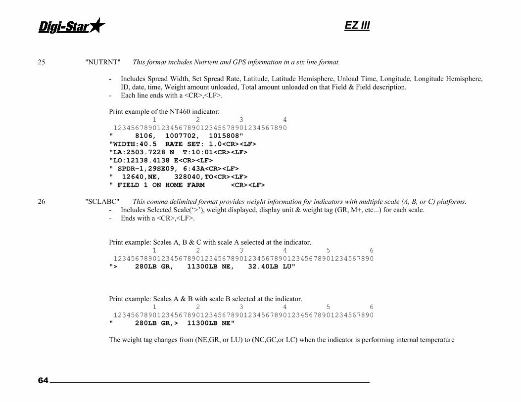
EZ III
64
25 "NUTRNT" This format includes Nutrient and GPS information in a six line format.
- Includes Spread Width, Set Spread Rate, Latitude, Latitude Hemisphere, Unload Time, Longitude, Longitude Hemisphere,
ID, date, time, Weight amount unloaded, Total amount unloaded on that Field & Field description. - Each line ends with a <CR>,<LF>.
Print example of the NT460 indicator: 1 2 3 4
1234567890123456789012345678901234567890
" 8106, 1007702, 1015808"
"WIDTH:40.5 RATE SET: 1.0<CR><LF>
"LA:2503.7228 N T:10:01<CR><LF>
"LO:12138.4138 E<CR><LF>
" SPDR-1,29SE09, 6:43A<CR><LF>
" 12640,NE, 328040,TO<CR><LF>
" FIELD 1 ON HOME FARM <CR><LF>
26 "SCLABC" This comma delimited format provides weight information for indicators with multiple scale (A, B, or C) platforms.
- Includes Selected Scale(‘>’), weight displayed, display unit & weight tag (GR, M+, etc...) for each scale. - Ends with a <CR>,<LF>.
Print example: Scales A, B & C with scale A selected at the indicator. 1 2 3 4 5 6
123456789012345678901234567890123456789012345678901234567890
"> 280LB GR, 11300LB NE, 32.40LB LU"
Print example: Scales A & B with scale B selected at the indicator. 1 2 3 4 5 6
123456789012345678901234567890123456789012345678901234567890
" 280LB GR,> 11300LB NE"
The weight tag changes from (NE,GR, or LU) to (NC,GC,or LC) when the indicator is performing internal temperature

Technical Manual
D3739 65
26 "SCLABC" (Continued)
calibrations ( which can take up to three seconds ). The weight sent at this time is the same weight prior to internal temperature calibrations. This occurs every 20 minutes but is done several times during the first 20 minutes after power up.
Print example: Scales A & B with scale B selected at the indicator. Both scales are being calibrated. 1 2 3
123456789012345678901234567890
" 280LB GC,> 11300LB NC"
The weight will appear as " 999999" with the “ES” weight tag when the operator is in the Short or Long Form Menu’s.
Print example: Scales A & B with scale B selected at the indicator. The B scale is in setup. 1 2 3
123456789012345678901234567890
" 280LB GR,> 999999LB ES"
The weight will appear as " 999999" with the “ER” weight tag when weighing errors (+/- RANGE,CHK AD,OVERCAP etc..) are detected by the scale.
Print example: Scales A & B with scale A selected at the indicator. The B scale has an error. 1 2 3
123456789012345678901234567890
"> 280LB GR, 999999LB ER"
27 "PRWTRC" This comma delimited format includes more information for batching weighing including “timer” or “mix counter”. Includes Preset, Net Weight, Gross Weight, Display unit, Command Originator, ‘M' if unit detects motion, weight tag (GR, M+, etc...), ID, Total Rotation Count, Date, Time.
- Ends with a <CR>,<LF>.
Print example: 1 2 3 4 5 6 7
1234567890123456789012345678901234567890123456789012345678901234567890
" 400, 180, 540,LB,O,M,GR,TRUCK1, 35,05JN12,00:01:15,10:48A, "
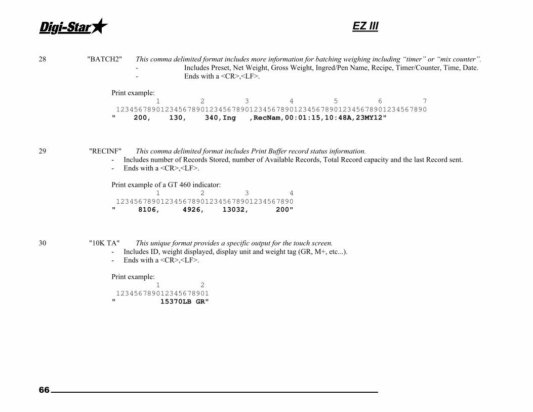
EZ III
66
28 "BATCH2" This comma delimited format includes more information for batching weighing including “timer” or “mix counter”.
- Includes Preset, Net Weight, Gross Weight, Ingred/Pen Name, Recipe, Timer/Counter, Time, Date. - Ends with a <CR>,<LF>.
Print example: 1 2 3 4 5 6 7
1234567890123456789012345678901234567890123456789012345678901234567890
" 200, 130, 340,Ing ,RecNam,00:01:15,10:48A,23MY12"
29 "RECINF" This comma delimited format includes Print Buffer record status information. - Includes number of Records Stored, number of Available Records, Total Record capacity and the last Record sent. - Ends with a <CR>,<LF>.
Print example of a GT 460 indicator: 1 2 3 4
1234567890123456789012345678901234567890
" 8106, 4926, 13032, 200"
30 "10K TA" This unique format provides a specific output for the touch screen. - Includes ID, weight displayed, display unit and weight tag (GR, M+, etc...). - Ends with a <CR>,<LF>.
Print example: 1 2
123456789012345678901
" 15370LB GR"

Technical Manual
D3739 67
31 “PRTST1” This comma delimited format includes information specific for the ST3400& 2520 scale (1 line).
- Includes Field ID, Bin, Mode (Auto/manual), Weight Dispensed, weight tag, (GR, M+, etc...), Preset, Print Accumulated Weight, Print Accumulator Tag (PA), Date, Time.
- Ends with a <CR>,<LF>.
Print example: 1 2 3 4 5 6 7
1234567890123456789012345678901234567890123456789012345678901234567890
"BACK40, BIN1, AUTO,- 252,GR, 250LB PR, 2652,PA,10AP13, 8:15A"
32 “PRTST3” This comma delimited format includes information specific for the ST3400 & 2520 scale (3 line).
- Includes Field ID, Bin, Mode (Auto/manual), Weight Dispensed, weight tag, (GR, M+, etc...), Preset, Print Accumulated Weight, Print Accumulator Tag (PA), Date, Time.
- Each line ends with a <CR>,<LF>.
Print example: 1 2 3 4
1234567890123456789012345678901234567890
"BACK40, BIN1, AUTO,”
“- 252,GR, 250LB PR, 2562,PA,”
“10AP13, 8:16A"

EZ III
68