extremely high-resolution tip-tilt-piston mirror mechanism...
TRANSCRIPT
SPIE Symposium on Astronomical Telescopes & Instrumentation 2000, 4007-48, Munich, Germany March 2000p. 1/8
_______________________________
* Correspondence: Email: [email protected]; www.csem.ch; Tel: +41 32 720-5443, Fax: +41 32 720-5720
Extremely high-resolution tip-tilt-piston mirror mechanism forthe VLT-NAOS field selector
P. Spanoudakis*, L. Zago, O. Chételat, R. Gentsch, F. Mato Mira
Centre Suisse d’Electronique et de MicrotechniqueJaquet-Droz 1, 2007 Neuchâtel
Switzerland
ABSTRACT
NAOS (Nasmyth Adaptive Optics System) is the adaptive optics system presently developed for the ESO VLT. The fieldselectors are to feed the NAOS wavefront sensor with the light coming from an appropriate reference source which can beup to 1 arcmin (on the sky) distant from the center of the field of view. A large input tip-tilt-piston mirror selects therequired part of the field of view. A second active mirror redirects the selected field to the wavefront sensor. Thedisplacement of both mirrors are synchronized. The NAOS Field Selector consists of two extremely accurate tip-tilt-pistonmirror mechanisms controlled in closed loop. Each mechanism provides a mechanical angle amplitude of ±6° with aresolution and mechanical stability of 0.42 arcsec rms over 20 minutes. This implies a dynamic range of 100'000 whichrequires an extremely accurate, very high resolution closed loop control. Both mirrors are made in SiC for low mass andinertia. The design configuration of the mechanism in based on three electromagnetic actuators 120° apart with the mobilemagnets mounted on flexure guides. The mirror is supported by a combination of flex pivots and a membrane for flexibilityin tilt and high radial stiffness. All kinematic joints consist of flexure elements so that the mechanism is essentiallyfrictionless. The control system is implemented on a VME bus operated with the VxWorks OS with high electricalresolution (= 18-bit) A/D and D/A interface boards. The controller has been carefully designed to achieve the best overallperformances, i.e., a very good noise rejection, and a relatively low settling time.
Keywords: Tip, tilt, pointing, mechanism, field selector, adaptive optics, flexures, mirror
1. INTRODUCTION
In the framework of the Very Large Telescope (VLT) project, the European Southern Observatory (ESO) is procuring anadvanced adaptive optics instrumentation called NAOS (Nasmyth Adaptive Optics System) with ONERA (France).Mounted at the Nasmyth focus of the telescope, NAOS holds an imaging instrument and rotates with the telescope Nasmythadapter rotator.
The NAOS Field Selector (FS) mechanisms provide a tip-tilt movement of a flat, 90 mm diameter mirror for the adaptiveoptics of the ESO VLT. The mechanisms are designed to provide a mechanical angle amplitude of ±6°. The mostchallenging technical requirement is the demanded resolution of 0.42 arcsec which is also the mechanical stability valuerequired over 20 minutes. The dynamic range of about 100'000 means a 17-bit accuracy end-to-end for the entire system.
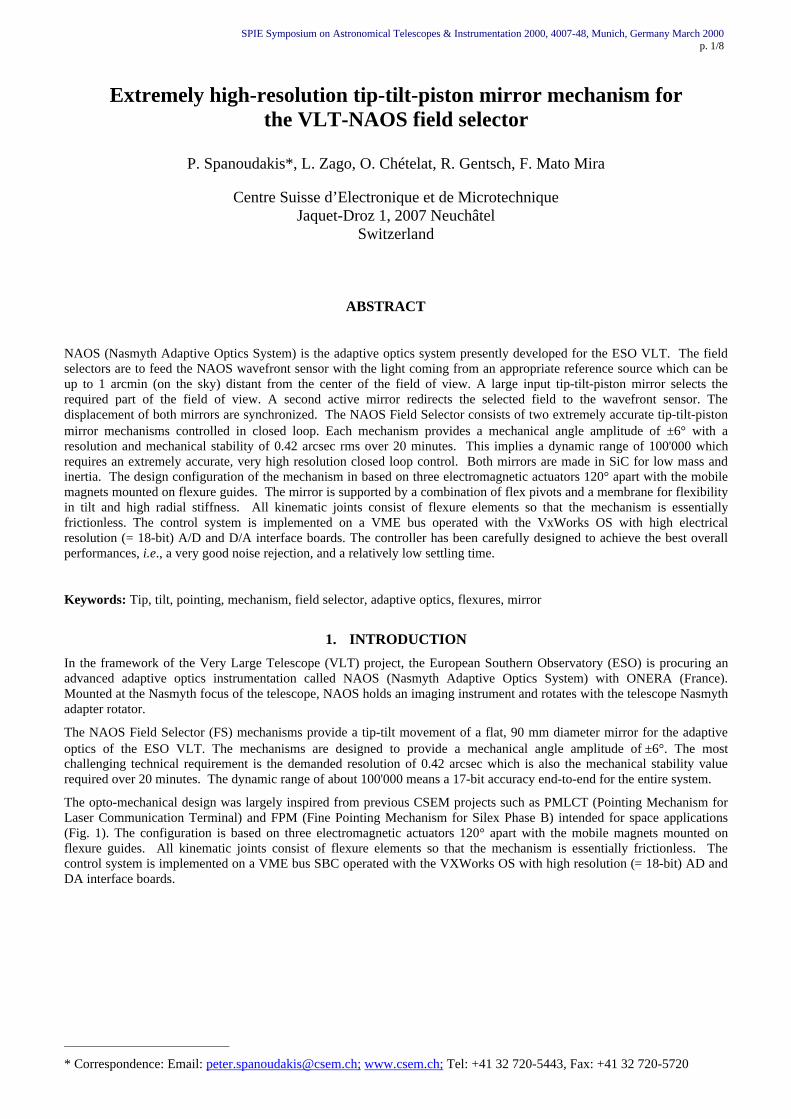
The opto-mechanical design was largely inspired from previous CSEM projects such as PMLCT (Pointing Mechanism forLaser Communication Terminal) and FPM (Fine Pointing Mechanism for Silex Phase B) intended for space applications(Fig. 1). The configuration is based on three electromagnetic actuators 120° apart with the mobile magnets mounted onflexure guides. All kinematic joints consist of flexure elements so that the mechanism is essentially frictionless. Thecontrol system is implemented on a VME bus SBC operated with the VXWorks OS with high resolution (= 18-bit) AD andDA interface boards.
SPIE Symposium on Astronomical Telescopes & Instrumentation 2000, 4007-48, Munich, Germany March 2000p. 2/8
Fig. 1: Photograph of two-axis tilt fine-pointing assembly (PMLCT prototype)
2. FIELD SELECTOR SPECIFICATIONS
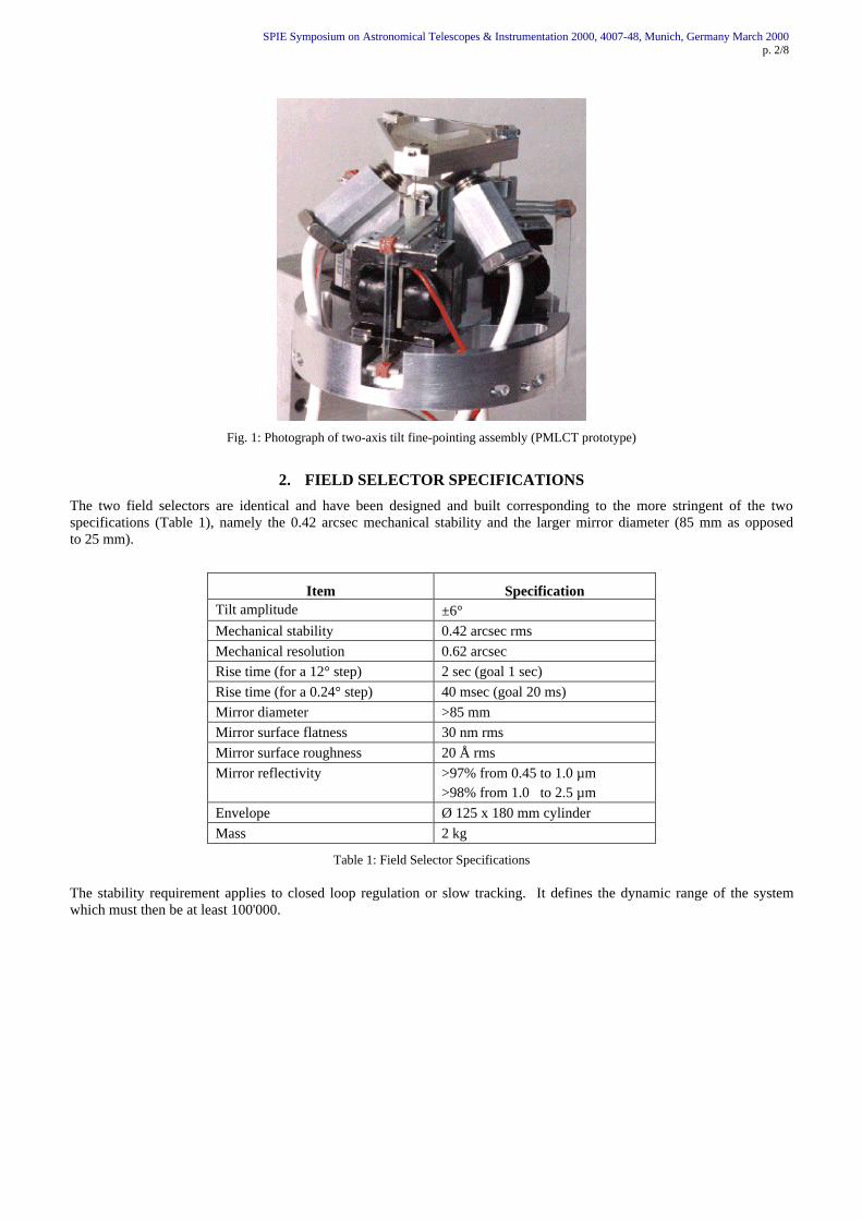
The two field selectors are identical and have been designed and built corresponding to the more stringent of the twospecifications (Table 1), namely the 0.42 arcsec mechanical stability and the larger mirror diameter (85 mm as opposedto 25 mm).
Item SpecificationTilt amplitude ±6°Mechanical stability 0.42 arcsec rmsMechanical resolution 0.62 arcsecRise time (for a 12° step) 2 sec (goal 1 sec)Rise time (for a 0.24° step) 40 msec (goal 20 ms)Mirror diameter >85 mmMirror surface flatness 30 nm rmsMirror surface roughness 20 Å rmsMirror reflectivity >97% from 0.45 to 1.0 µm
>98% from 1.0 to 2.5 µmEnvelope Ø 125 x 180 mm cylinderMass 2 kg
Table 1: Field Selector Specifications
The stability requirement applies to closed loop regulation or slow tracking. It defines the dynamic range of the systemwhich must then be at least 100'000.
SPIE Symposium on Astronomical Telescopes & Instrumentation 2000, 4007-48, Munich, Germany March 2000p. 3/8
3. FIELD SELECTOR MECHANISM DESCRIPTION
3.1. Suspension and Actuator Guiding
The pivotless tip-tilt mechanism implements frictionless supports of three linear actuators with a 3-rod suspension (Fig. 2)which allows the fine pointing mirror to combine the high static deflection range with a high frequency bandwidth and stepresponse performance.
actuator suspension (3x)
steel wire
mirror
virtual centre oftilt rotation
mirror mount
Balancedmirror support
housinginterface
mobile memberof actuator
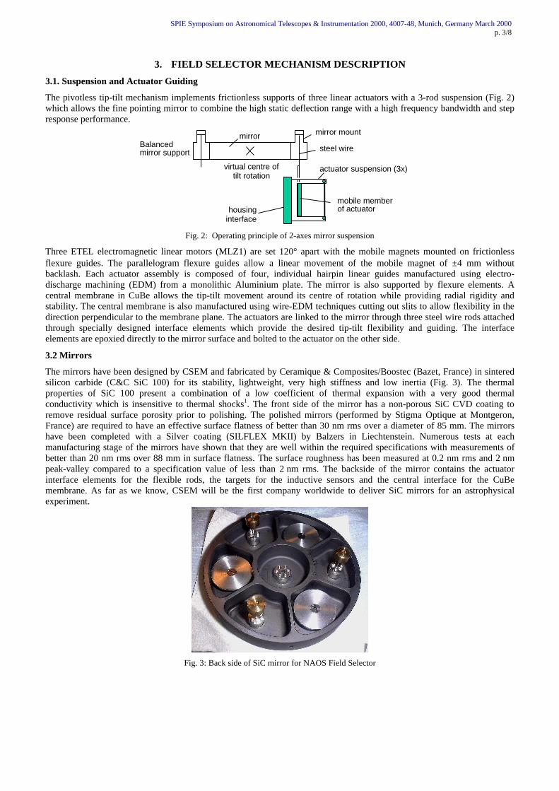
Fig. 2: Operating principle of 2-axes mirror suspension
Three ETEL electromagnetic linear motors (MLZ1) are set 120° apart with the mobile magnets mounted on frictionlessflexure guides. The parallelogram flexure guides allow a linear movement of the mobile magnet of ±4 mm withoutbacklash. Each actuator assembly is composed of four, individual hairpin linear guides manufactured using electro-discharge machining (EDM) from a monolithic Aluminium plate. The mirror is also supported by flexure elements. Acentral membrane in CuBe allows the tip-tilt movement around its centre of rotation while providing radial rigidity andstability. The central membrane is also manufactured using wire-EDM techniques cutting out slits to allow flexibility in thedirection perpendicular to the membrane plane. The actuators are linked to the mirror through three steel wire rods attachedthrough specially designed interface elements which provide the desired tip-tilt flexibility and guiding. The interfaceelements are epoxied directly to the mirror surface and bolted to the actuator on the other side.
3.2 Mirrors
The mirrors have been designed by CSEM and fabricated by Ceramique & Composites/Boostec (Bazet, France) in sinteredsilicon carbide (C&C SiC 100) for its stability, lightweight, very high stiffness and low inertia (Fig. 3). The thermalproperties of SiC 100 present a combination of a low coefficient of thermal expansion with a very good thermalconductivity which is insensitive to thermal shocks1. The front side of the mirror has a non-porous SiC CVD coating toremove residual surface porosity prior to polishing. The polished mirrors (performed by Stigma Optique at Montgeron,France) are required to have an effective surface flatness of better than 30 nm rms over a diameter of 85 mm. The mirrorshave been completed with a Silver coating (SILFLEX MKII) by Balzers in Liechtenstein. Numerous tests at eachmanufacturing stage of the mirrors have shown that they are well within the required specifications with measurements ofbetter than 20 nm rms over 88 mm in surface flatness. The surface roughness has been measured at 0.2 nm rms and 2 nmpeak-valley compared to a specification value of less than 2 nm rms. The backside of the mirror contains the actuatorinterface elements for the flexible rods, the targets for the inductive sensors and the central interface for the CuBemembrane. As far as we know, CSEM will be the first company worldwide to deliver SiC mirrors for an astrophysicalexperiment.
Fig. 3: Back side of SiC mirror for NAOS Field Selector
SPIE Symposium on Astronomical Telescopes & Instrumentation 2000, 4007-48, Munich, Germany March 2000p. 4/8
3.3 Position Sensors
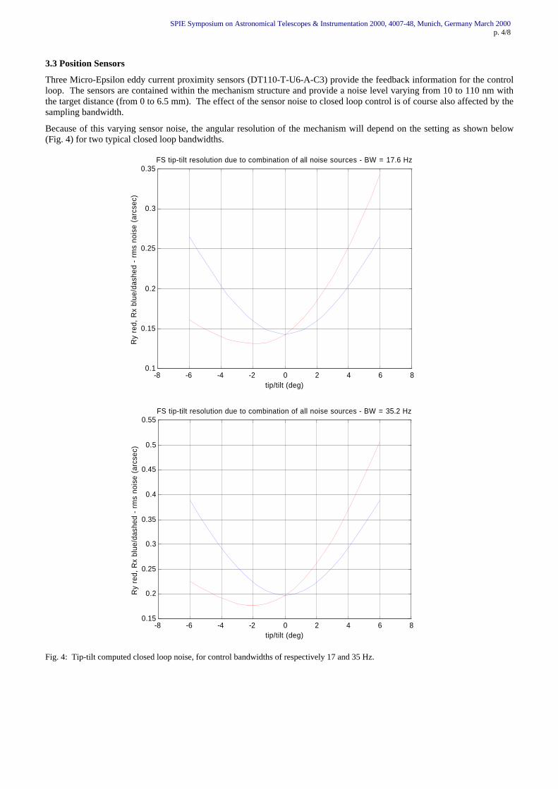
Three Micro-Epsilon eddy current proximity sensors (DT110-T-U6-A-C3) provide the feedback information for the controlloop. The sensors are contained within the mechanism structure and provide a noise level varying from 10 to 110 nm withthe target distance (from 0 to 6.5 mm). The effect of the sensor noise to closed loop control is of course also affected by thesampling bandwidth.
Because of this varying sensor noise, the angular resolution of the mechanism will depend on the setting as shown below(Fig. 4) for two typical closed loop bandwidths.
-8 -6 -4 -2 0 2 4 6 80.1
0.15
0.2
0.25
0.3
0.35
tip/tilt (deg)
FS tip-tilt resolution due to combination of all noise sources - BW = 17.6 Hz
Ry
red,
Rx
blue
/das
hed
- rm
s no
ise
(arc
sec)
-8 -6 -4 -2 0 2 4 6 80.15
0.2
0.25
0.3
0.35
0.4
0.45
0.5
0.55
tip/tilt (deg)
FS tip-tilt resolution due to combination of all noise sources - BW = 35.2 Hz
Ry
red,
Rx
blue
/das
hed
- rm
s no
ise
(arc
sec)
Fig. 4: Tip-tilt computed closed loop noise, for control bandwidths of respectively 17 and 35 Hz.
SPIE Symposium on Astronomical Telescopes & Instrumentation 2000, 4007-48, Munich, Germany March 2000p. 5/8
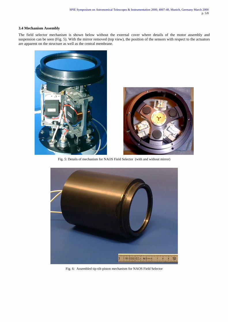
3.4 Mechanism Assembly
The field selector mechanism is shown below without the external cover where details of the motor assembly andsuspension can be seen (Fig. 5). With the mirror removed (top view), the position of the sensors with respect to the actuatorsare apparent on the structure as well as the central membrane.
Fig. 5: Details of mechanism for NAOS Field Selector (with and without mirror)
Fig. 6: Assembled tip-tilt-piston mechanism for NAOS Field Selector
SPIE Symposium on Astronomical Telescopes & Instrumentation 2000, 4007-48, Munich, Germany March 2000p. 6/8
4. CONTROL SYSTEM
The control system of the field selectors is targeted to the overall 17-bit accuracy objective and comprises both analog anddigital elements: signal conditioners for the proximity sensors, motor amplifiers, a VME-bus control system with highresolution ADC and DAC boards.
To ensure the stability requirement in spite of possible drifts of the lower bits of the ADC, a CSEM custom electronic boardperforms, at regular intervals, a recalibration of the sensor signals with respect to a very stable voltage reference. During thetime one loop is open for calibration, another channel is used to get information from the position sensor so that the systemis virtually kept in closed loop at all times.
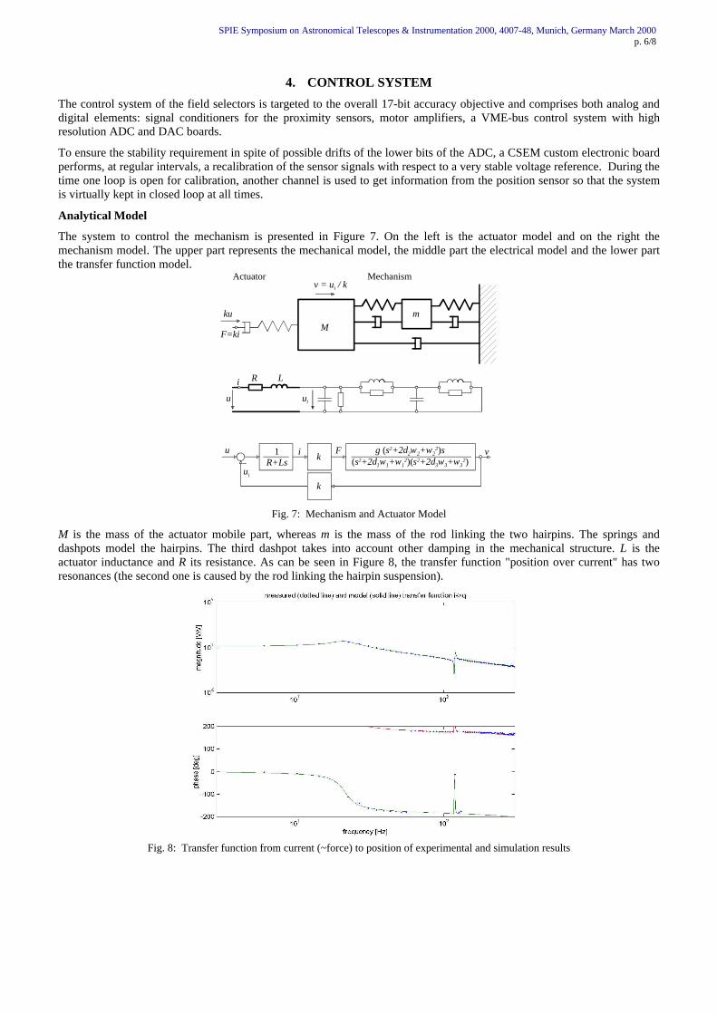
Analytical Model
The system to control the mechanism is presented in Figure 7. On the left is the actuator model and on the right themechanism model. The upper part represents the mechanical model, the middle part the electrical model and the lower partthe transfer function model.
Mm
R L
Actuator Mechanism
u ui
ku
v = ui / k
F=ki
i
1R+Ls
g (s2+2δ2ω2+ω22)s
(s2+2δ1ω1+ω12)(s2+2δ3ω3+ω3
2)k
k
u
ui
i F v
Fig. 7: Mechanism and Actuator Model
M is the mass of the actuator mobile part, whereas m is the mass of the rod linking the two hairpins. The springs anddashpots model the hairpins. The third dashpot takes into account other damping in the mechanical structure. L is theactuator inductance and R its resistance. As can be seen in Figure 8, the transfer function "position over current" has tworesonances (the second one is caused by the rod linking the hairpin suspension).
Fig. 8: Transfer function from current (~force) to position of experimental and simulation results
SPIE Symposium on Astronomical Telescopes & Instrumentation 2000, 4007-48, Munich, Germany March 2000p. 7/8
The current is controlled by the inner loop and the position by the outer loop as depicted in the closed loop system below(Fig. 9).
reference qr
u
q
i
plant
e ef
outer loop controller
i if
inner loop controller
z
1
computation timeSum2Sum
Fig. 9: Mechanism Controller
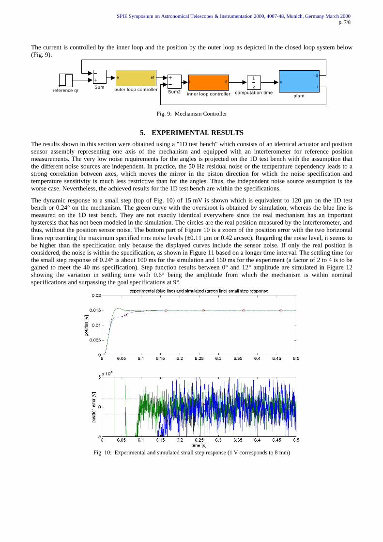
5. EXPERIMENTAL RESULTS
The results shown in this section were obtained using a "1D test bench" which consists of an identical actuator and positionsensor assembly representing one axis of the mechanism and equipped with an interferometer for reference positionmeasurements. The very low noise requirements for the angles is projected on the 1D test bench with the assumption thatthe different noise sources are independent. In practice, the 50 Hz residual noise or the temperature dependency leads to astrong correlation between axes, which moves the mirror in the piston direction for which the noise specification andtemperature sensitivity is much less restrictive than for the angles. Thus, the independent noise source assumption is theworse case. Nevertheless, the achieved results for the 1D test bench are within the specifications.
The dynamic response to a small step (top of Fig. 10) of 15 mV is shown which is equivalent to 120 µm on the 1D testbench or 0.24° on the mechanism. The green curve with the overshoot is obtained by simulation, whereas the blue line ismeasured on the 1D test bench. They are not exactly identical everywhere since the real mechanism has an importanthysteresis that has not been modeled in the simulation. The circles are the real position measured by the interferometer, andthus, without the position sensor noise. The bottom part of Figure 10 is a zoom of the position error with the two horizontallines representing the maximum specified rms noise levels (±0.11 µm or 0.42 arcsec). Regarding the noise level, it seems tobe higher than the specification only because the displayed curves include the sensor noise. If only the real position isconsidered, the noise is within the specification, as shown in Figure 11 based on a longer time interval. The settling time forthe small step response of 0.24° is about 100 ms for the simulation and 160 ms for the experiment (a factor of 2 to 4 is to begained to meet the 40 ms specification). Step function results between 0° and 12° amplitude are simulated in Figure 12showing the variation in settling time with 0.6° being the amplitude from which the mechanism is within nominalspecifications and surpassing the goal specifications at 9°.
Fig. 10: Experimental and simulated small step response (1 V corresponds to 8 mm)
SPIE Symposium on Astronomical Telescopes & Instrumentation 2000, 4007-48, Munich, Germany March 2000p. 8/8
Fig. 11: Experimental (top) and simulated (bottom) mechanical stability (1 V corresponds to 8 mm)
0 1 2 3 4 5 60
0.2
0.4
0.6
0.8
1
1.2
1.4
1.6
1.8
2step response settling time (dotted lines are the nominal and goal specifications)
settlin
g tim
e [s
]
step (position) [mm]
Fig. 12: Simulated settling response time as a function of step amplitude (6 mm = 12° tilt)
6. CONCLUSION
This work has demonstrated that a tip-tilt-piston mechanism for fine pointing applications based on electro-magneticactuators and high resolution inductive sensors can meet stringent mechanical stability requirements such as the 0.42 arcsecrms over 20 minutes specified for NAOS. Stability and pointing performance has been met by incorporating a combinationof techniques such as the use of flexures for frictionless guiding and suspension, a SiC mirror for low mass and highstiffness, a control system comprised of both analog and digital elements, signal conditioners and high resolution ADC andDAC interface boards. A special electronic board is also included which performs a recalibration of the sensor signals withrespect to a very stable reference voltage. Simulation results were first verified experimentally on a 1D actuator test benchto evaluate performance characteristics and noise sources. Test results have confirmed that the achieved performance iswithin specifications and has allowed the simulation model to be validated prior to testing on the field selector mirrormechanisms.
ACKNOWLEDGEMENTS
A number of CSEM co-workers contributed in various forms to the work presented here: we would like to name inparticular G. Besson, M. Bogdanski, P.M. Genequand, L. Giriens, I. Kjelberg, L. Mealares and E. Onillon
REFERENCES1. Pascal Antoine, Michel Fruit, “SiC Telescope demonstrator (mirrors & structures) opto-mechanical performances”,
proceedings Design and Engineering of Optical Systems II, EUROPTO Series, Volume 3737, OES/SPIE Symposium,p.418, Berlin, Germany 25-27 May 1999.