trim and tilt - justanswer · 326 trim and tilt service chart service chart 20” 115 hp models...
TRANSCRIPT

TRIM AND TILT
325
13
TRIM AND TILT
TABLE OF CONTENTS
SERVICE CHART . . . . . . . . . . . . . . . . . . . . . . . . . . . . . . . . . . . . . . . . . . . . . . . . . . . . . . . . . . . . . . . . . . . 326SYSTEM DESCRIPTION . . . . . . . . . . . . . . . . . . . . . . . . . . . . . . . . . . . . . . . . . . . . . . . . . . . . . . . . . . . . . 328MODES OF OPERATION (THREE PISTON SYSTEM) . . . . . . . . . . . . . . . . . . . . . . . . . . . . . . . . . . . . . . 329ROUTINE INSPECTIONS . . . . . . . . . . . . . . . . . . . . . . . . . . . . . . . . . . . . . . . . . . . . . . . . . . . . . . . . . . . . 335
GENERAL . . . . . . . . . . . . . . . . . . . . . . . . . . . . . . . . . . . . . . . . . . . . . . . . . . . . . . . . . . . . . . . . . . . . . . 335RESERVOIR FLUID . . . . . . . . . . . . . . . . . . . . . . . . . . . . . . . . . . . . . . . . . . . . . . . . . . . . . . . . . . . . . . . . 335MANUAL RELEASE VALVE . . . . . . . . . . . . . . . . . . . . . . . . . . . . . . . . . . . . . . . . . . . . . . . . . . . . . . . . . . 335STERN BRACKETS . . . . . . . . . . . . . . . . . . . . . . . . . . . . . . . . . . . . . . . . . . . . . . . . . . . . . . . . . . . . . . . 335
TROUBLESHOOTING . . . . . . . . . . . . . . . . . . . . . . . . . . . . . . . . . . . . . . . . . . . . . . . . . . . . . . . . . . . . . . . 335SINGLE PISTON SYSTEM . . . . . . . . . . . . . . . . . . . . . . . . . . . . . . . . . . . . . . . . . . . . . . . . . . . . . . . . . . . 335THREE PISTON SYSTEM . . . . . . . . . . . . . . . . . . . . . . . . . . . . . . . . . . . . . . . . . . . . . . . . . . . . . . . . . . . . 336
ELECTRICAL CIRCUIT TESTS . . . . . . . . . . . . . . . . . . . . . . . . . . . . . . . . . . . . . . . . . . . . . . . . . . . . . . . . 339RELAY TESTING . . . . . . . . . . . . . . . . . . . . . . . . . . . . . . . . . . . . . . . . . . . . . . . . . . . . . . . . . . . . . . . . . 339TRIM AND TILT MOTOR CURRENT DRAW TESTS . . . . . . . . . . . . . . . . . . . . . . . . . . . . . . . . . . . . . . . . . . 339TRIM AND TILT MOTOR NO LOAD TEST . . . . . . . . . . . . . . . . . . . . . . . . . . . . . . . . . . . . . . . . . . . . . . . . 340TRIM GAUGE TEST . . . . . . . . . . . . . . . . . . . . . . . . . . . . . . . . . . . . . . . . . . . . . . . . . . . . . . . . . . . . . . . 341TRIM SENDER TEST . . . . . . . . . . . . . . . . . . . . . . . . . . . . . . . . . . . . . . . . . . . . . . . . . . . . . . . . . . . . . . . 342
TRIM AND TILT REPLACEMENT . . . . . . . . . . . . . . . . . . . . . . . . . . . . . . . . . . . . . . . . . . . . . . . . . . . . . . 342REMOVAL . . . . . . . . . . . . . . . . . . . . . . . . . . . . . . . . . . . . . . . . . . . . . . . . . . . . . . . . . . . . . . . . . . . . . . 342INSTALLATION . . . . . . . . . . . . . . . . . . . . . . . . . . . . . . . . . . . . . . . . . . . . . . . . . . . . . . . . . . . . . . . . . . 344
SERVICING–SINGLE PISTON SYSTEM . . . . . . . . . . . . . . . . . . . . . . . . . . . . . . . . . . . . . . . . . . . . . . . . . 345DISASSEMBLY . . . . . . . . . . . . . . . . . . . . . . . . . . . . . . . . . . . . . . . . . . . . . . . . . . . . . . . . . . . . . . . . . . . 345ASSEMBLY . . . . . . . . . . . . . . . . . . . . . . . . . . . . . . . . . . . . . . . . . . . . . . . . . . . . . . . . . . . . . . . . . . . . . 346
SERVICING – THREE PISTON SYSTEM . . . . . . . . . . . . . . . . . . . . . . . . . . . . . . . . . . . . . . . . . . . . . . . . 347DISASSEMBLY . . . . . . . . . . . . . . . . . . . . . . . . . . . . . . . . . . . . . . . . . . . . . . . . . . . . . . . . . . . . . . . . . . . 347TILT PISTON REMOVAL . . . . . . . . . . . . . . . . . . . . . . . . . . . . . . . . . . . . . . . . . . . . . . . . . . . . . . . . . . . . 350TILT PISTON IDENTIFICATION . . . . . . . . . . . . . . . . . . . . . . . . . . . . . . . . . . . . . . . . . . . . . . . . . . . . . . . 351TILT PISTON ASSEMBLY . . . . . . . . . . . . . . . . . . . . . . . . . . . . . . . . . . . . . . . . . . . . . . . . . . . . . . . . . . . 351TILT ROD ASSEMBLY . . . . . . . . . . . . . . . . . . . . . . . . . . . . . . . . . . . . . . . . . . . . . . . . . . . . . . . . . . . . . . 352TRIM ROD REMOVAL . . . . . . . . . . . . . . . . . . . . . . . . . . . . . . . . . . . . . . . . . . . . . . . . . . . . . . . . . . . . . . 353TRIM ROD ASSEMBLY . . . . . . . . . . . . . . . . . . . . . . . . . . . . . . . . . . . . . . . . . . . . . . . . . . . . . . . . . . . . . 354MANIFOLD AND RESERVOIR INSTALLATION . . . . . . . . . . . . . . . . . . . . . . . . . . . . . . . . . . . . . . . . . . . . . 355TRIM ROD INSTALLATION . . . . . . . . . . . . . . . . . . . . . . . . . . . . . . . . . . . . . . . . . . . . . . . . . . . . . . . . . . 356TILT ROD INSTALLATION . . . . . . . . . . . . . . . . . . . . . . . . . . . . . . . . . . . . . . . . . . . . . . . . . . . . . . . . . . . 357MOTOR INSTALLATION . . . . . . . . . . . . . . . . . . . . . . . . . . . . . . . . . . . . . . . . . . . . . . . . . . . . . . . . . . . . 357

326
TRIM AND TILTSERVICE CHART
SERVICE CHART20” 115 HP MODELS (SINGLE PISTON SYSTEM)
005002
A Triple-Guard Grease
W Biodegradable TNT Fluid
30 to 50 In. lbs.(4 to 5.6 N·m)
A
A
W45 to 55 In. lbs.(5 to 6 N·m)
45 to 55 In. lbs.(5 to 6 N·m)
TRIM AND TILTSERVICE CHART
327
13
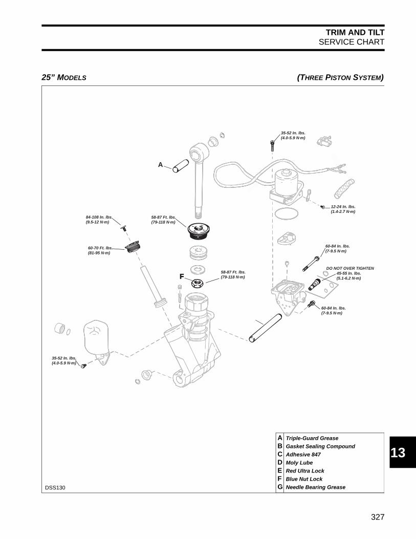
25” MODELS (THREE PISTON SYSTEM)
DSS130
A Triple-Guard Grease
B Gasket Sealing Compound
C Adhesive 847
D Moly Lube
E Red Ultra Lock
F Blue Nut Lock
G Needle Bearing Grease
60-70 Ft. lbs.(81-95 N·m)
DO NOT OVER TIGHTEN
84-108 In. lbs.(9.5-12 N·m)
58-87 Ft. lbs.(79-118 N·m)
35-52 In. lbs.(4.0-5.9 N·m)
60-84 In. lbs.(7-9.5 N·m)
45-55 In. lbs.(5.1-6.2 N·m)
35-52 In. lbs.(4.0-5.9 N·m)
60-84 In. lbs.(7-9.5 N·m)
12-24 In. lbs.(1.4-2.7 N·m)
A
58-87 Ft. lbs.(79-118 N·m) FF

328
TRIM AND TILTSYSTEM DESCRIPTION
SYSTEM DESCRIPTIONThe power trim/tilt hydraulic system is completelycontained between the outboard's stern brackets.
The system consists of:• Electric motor• Oil reservoir• Pump manifold assembly• Cylinder body assembly
Optimal boat and outboard performance can beachieved by adjusting (trimming) the angle of out-board propeller thrust. The first 15° of outboardmovement is considered trim range.
Outboard movement beyond the trim range isconsidered tilting. Tilting of the outboard may bedesired for shallow water drive and for traile-ring/storage. The tilt cylinder moves the outboardthrough the tilt range (final 50°).
A tilt relief valve limits the propeller thrust load thatwill be supported by the unit in tilt range. As pres-sure increases, the outboard will tilt down to thetop of the trim range.
IMPORTANT: When in tilt range, make surewater is available to gearcase water pickups.
Manual AdjustmentThe outboard can be manually raised or loweredthrough the entire trim and tilt range by openingthe manual release valve a minimum of threeturns. The manual release valve must be closedand torqued 45 to 55 in. lbs. (5 to 6 N·m) to holdthe outboard in position and before normal opera-tion can be resumed.
Trailering Bracket And Tilt SupportUse the trailering bracket to support the outboardwhen trailering in the tilted position. This bracketprotects the hydraulic system from damage.
Tilt the outboard up fully, engage the bracket, thentilt the outboard down until the bracket is firmly inposition.
For mooring or storing the boat with the outboardtilted, a tilt support is provided to support the out-board.
IMPORTANT: The tilt support must not be usedto support the outboard while trailering.
1. Manual release valve 001988
1
1. Trailering Bracket 001987
1. Tilt support 002279
1
1
329
TRIM AND TILTMODES OF OPERATION (THREE PISTON SYSTEM)
13
MODES OF OPERATION (Three Piston System)The trim/tilt hydraulic assembly achieves trim andtilt movement through the following modes ofoperation.
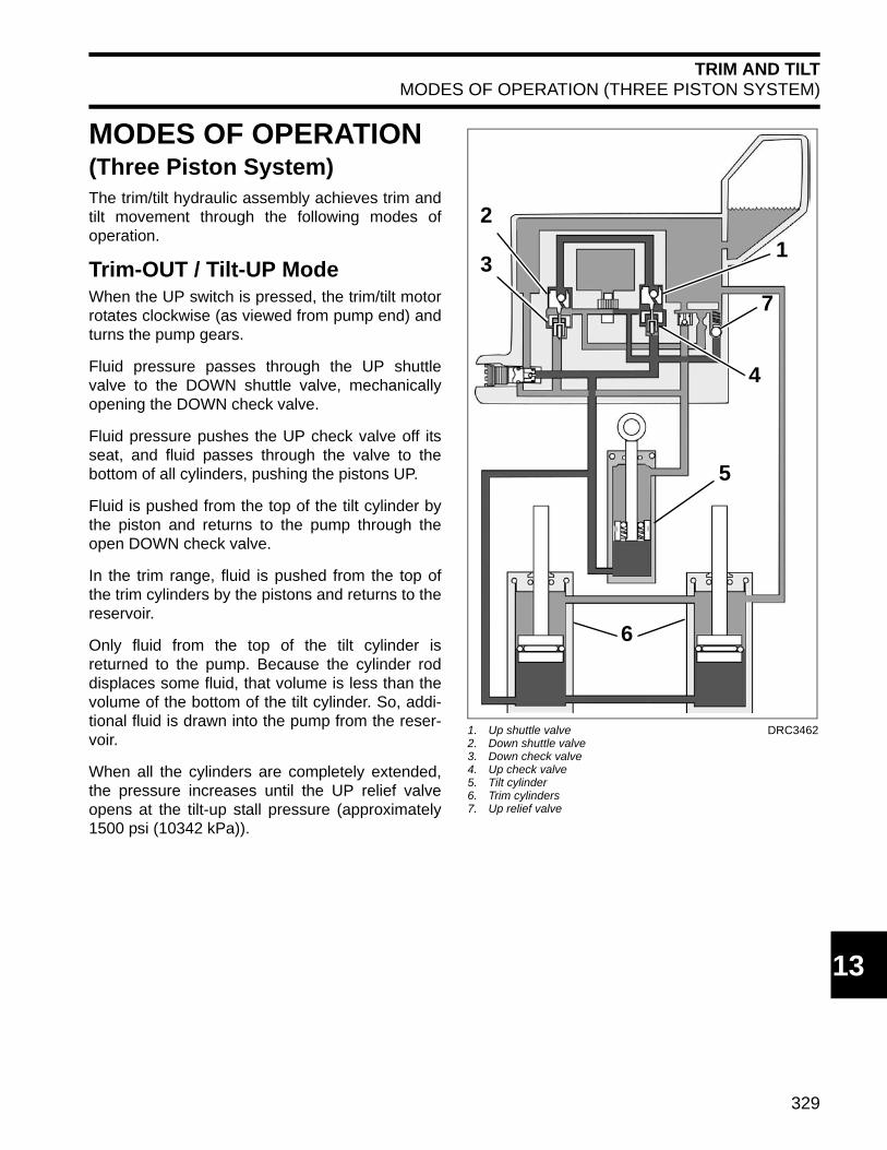
Trim-OUT / Tilt-UP ModeWhen the UP switch is pressed, the trim/tilt motorrotates clockwise (as viewed from pump end) andturns the pump gears.
Fluid pressure passes through the UP shuttlevalve to the DOWN shuttle valve, mechanicallyopening the DOWN check valve.
Fluid pressure pushes the UP check valve off itsseat, and fluid passes through the valve to thebottom of all cylinders, pushing the pistons UP.
Fluid is pushed from the top of the tilt cylinder bythe piston and returns to the pump through theopen DOWN check valve.
In the trim range, fluid is pushed from the top ofthe trim cylinders by the pistons and returns to thereservoir.
Only fluid from the top of the tilt cylinder isreturned to the pump. Because the cylinder roddisplaces some fluid, that volume is less than thevolume of the bottom of the tilt cylinder. So, addi-tional fluid is drawn into the pump from the reser-voir.
When all the cylinders are completely extended,the pressure increases until the UP relief valveopens at the tilt-up stall pressure (approximately1500 psi (10342 kPa)).
1. Up shuttle valve2. Down shuttle valve3. Down check valve4. Up check valve5. Tilt cylinder6. Trim cylinders7. Up relief valve
DRC3462
2
31
7
4
5
6
330
TRIM AND TILTMODES OF OPERATION (THREE PISTON SYSTEM)
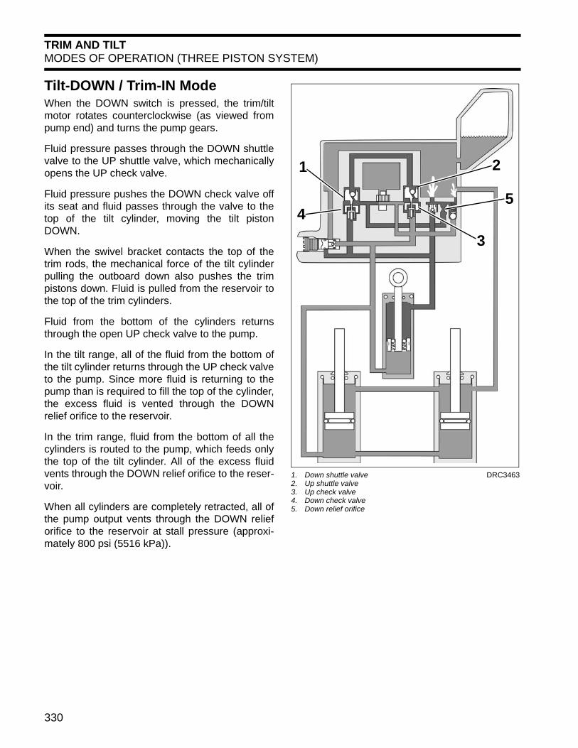
Tilt-DOWN / Trim-IN ModeWhen the DOWN switch is pressed, the trim/tiltmotor rotates counterclockwise (as viewed frompump end) and turns the pump gears.
Fluid pressure passes through the DOWN shuttlevalve to the UP shuttle valve, which mechanicallyopens the UP check valve.
Fluid pressure pushes the DOWN check valve offits seat and fluid passes through the valve to thetop of the tilt cylinder, moving the tilt pistonDOWN.
When the swivel bracket contacts the top of thetrim rods, the mechanical force of the tilt cylinderpulling the outboard down also pushes the trimpistons down. Fluid is pulled from the reservoir tothe top of the trim cylinders.
Fluid from the bottom of the cylinders returnsthrough the open UP check valve to the pump.
In the tilt range, all of the fluid from the bottom ofthe tilt cylinder returns through the UP check valveto the pump. Since more fluid is returning to thepump than is required to fill the top of the cylinder,the excess fluid is vented through the DOWNrelief orifice to the reservoir.
In the trim range, fluid from the bottom of all thecylinders is routed to the pump, which feeds onlythe top of the tilt cylinder. All of the excess fluidvents through the DOWN relief orifice to the reser-voir.
When all cylinders are completely retracted, all ofthe pump output vents through the DOWN relieforifice to the reservoir at stall pressure (approxi-mately 800 psi (5516 kPa)).
1. Down shuttle valve2. Up shuttle valve3. Up check valve4. Down check valve5. Down relief orifice
DRC3463
1 2
3
45

331
TRIM AND TILTMODES OF OPERATION (THREE PISTON SYSTEM)
13
Impact ReliefShould the gearcase hit an underwater object andthe outboard suddenly tilts up, the tilt cylinderextends. The fluid above the piston is com-pressed, producing high pressure.
This high pressure fluid passes through theimpact relief valves in the tilt piston, dissipatingmuch of the energy of the impact.
To return the outboard to its original position, thehydraulic unit must be operated in the DOWNdirection.
1. Impact relief valves DRC3467
1 1
332
TRIM AND TILTMODES OF OPERATION (THREE PISTON SYSTEM)
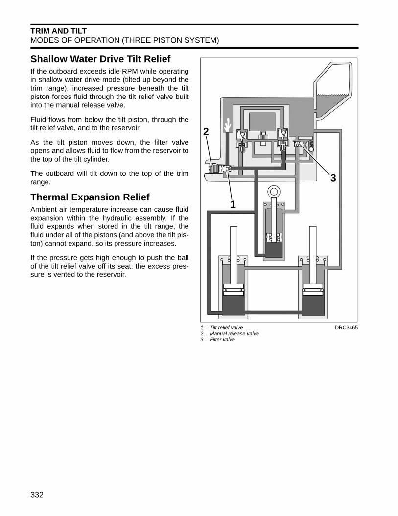
Shallow Water Drive Tilt ReliefIf the outboard exceeds idle RPM while operatingin shallow water drive mode (tilted up beyond thetrim range), increased pressure beneath the tiltpiston forces fluid through the tilt relief valve builtinto the manual release valve.
Fluid flows from below the tilt piston, through thetilt relief valve, and to the reservoir.
As the tilt piston moves down, the filter valveopens and allows fluid to flow from the reservoir tothe top of the tilt cylinder.
The outboard will tilt down to the top of the trimrange.
Thermal Expansion ReliefAmbient air temperature increase can cause fluidexpansion within the hydraulic assembly. If thefluid expands when stored in the tilt range, thefluid under all of the pistons (and above the tilt pis-ton) cannot expand, so its pressure increases.
If the pressure gets high enough to push the ballof the tilt relief valve off its seat, the excess pres-sure is vented to the reservoir.
1. Tilt relief valve2. Manual release valve3. Filter valve
DRC3465
1
2
3
333
TRIM AND TILTMODES OF OPERATION (THREE PISTON SYSTEM)
13
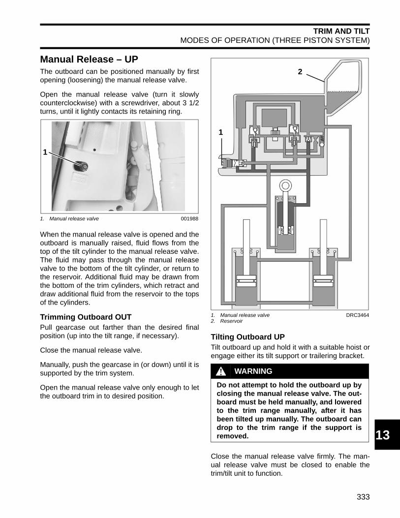
Manual Release – UP The outboard can be positioned manually by firstopening (loosening) the manual release valve.
Open the manual release valve (turn it slowlycounterclockwise) with a screwdriver, about 3 1/2turns, until it lightly contacts its retaining ring.
When the manual release valve is opened and theoutboard is manually raised, fluid flows from thetop of the tilt cylinder to the manual release valve.The fluid may pass through the manual releasevalve to the bottom of the tilt cylinder, or return tothe reservoir. Additional fluid may be drawn fromthe bottom of the trim cylinders, which retract anddraw additional fluid from the reservoir to the topsof the cylinders.
Trimming Outboard OUTPull gearcase out farther than the desired finalposition (up into the tilt range, if necessary).
Close the manual release valve.
Manually, push the gearcase in (or down) until it issupported by the trim system.
Open the manual release valve only enough to letthe outboard trim in to desired position.
Tilting Outboard UPTilt outboard up and hold it with a suitable hoist orengage either its tilt support or trailering bracket.
Close the manual release valve firmly. The man-ual release valve must be closed to enable thetrim/tilt unit to function.
1. Manual release valve 001988
1
1. Manual release valve2. Reservoir
DRC3464
WARNING
Do not attempt to hold the outboard up byclosing the manual release valve. The out-board must be held manually, and loweredto the trim range manually, after it hasbeen tilted up manually. The outboard candrop to the trim range if the support isremoved.
2
1

334
TRIM AND TILTMODES OF OPERATION (THREE PISTON SYSTEM)
Manual Release – DOWNWhen the manual release valve is opened and theoutboard is manually tilted down or trimmed in,fluid flows from the bottom of the tilt cylinder (inthe tilt range), or from the bottom of all of the cylin-ders (in the trim range), and past the manualrelease valve.
Fluid flows from the bottom of the tilt cylinder (inthe tilt range) to the top of the tilt cylinder. Theexcess fluid, equal to the volume of the piston rod,is vented to the reservoir.
In the trim range, the fluid from the bottom of allthree cylinders is vented to the reservoir, exceptfor the amount required to fill the top of the tilt cyl-inder.
After opening the manual release valve, close itfirmly. The manual release valve must be closedto enable the trim/tilt unit to function.
1. Manual release valve DRC3465
1

335
TRIM AND TILTROUTINE INSPECTIONS
13
ROUTINE INSPECTIONSGeneralCheck for external signs of fluid leakage. Correctcauses as necessary.
Check the battery to be sure it is in good operatingcondition.
Reservoir FluidCheck reservoir fluid level every three years orevery 300 operating hours. System capacity isapproximately 21 fl. oz. (620 ml).
Refer to Trim and Tilt on p. 37 for filling proce-dure.
Manual Release ValveCheck the manual release valve with a torquewrench.
IMPORTANT: Tighten valve to a torque of 45 to55 in. lbs. (5 to 6 N·m).
Stern BracketsInspect the stern brackets for binding.
Tighten starboard tilt tube nut to a torque of 45 to50 ft. lbs. (61 to 68 N·m).
TROUBLESHOOTINGSingle Piston SystemUse the following guidelines to check a single pis-ton trim/tilt unit that is not working correctly.
Cylinder Leakdown:• Manual release valve seals• External leaks
No reverse lock:• External leaks
No operation, motor runs:• Manual release valve open• Fluid level low• Pump coupler• Hydraulic pump
No tilt down:• Manual release valve• Fluid level
Slow performance:• Manual release valve• Fluid level low• Mechanical binding• Electric motor• Hydraulic pump
Unit locked in tilt up:• Mechanical binding• Hydraulic pump

336
TRIM AND TILTTROUBLESHOOTING
Three Piston SystemIf the power trim/tilt system has malfunctioned andthe cause has not been determined, the Symp-toms Chart on p. 336 should help locate theproblem.
Keep a manual release valve and a valve body instock for troubleshooting. Use these parts whenthe Service Procedures on p. 336 call for thesubstitution of known good parts.
If the trim/tilt does not work, and its motor neitherruns nor hums, troubleshoot the problem by refer-ring to TILT/TRIM RELAY TEST on p. 104.
If the outboard tilts part way up but not smoothly,or with a constant sound, there is probably air inthe system due to low fluid. Fill reservoir andbleed (purge air from) the system.
To test for mechanical binding, open the manualrelease valve and manually tilt the motor up anddown. If parts are binding, refer to MIDSECTIONsection.
If a V4 model will not lower from shallow waterdrive position at any throttle setting, or if a V6model will not stay in shallow water drive anddrops down at fast idle, the wrong manual releasevalve may be installed. Check for the identificationgroove in the face of the valve.
If the outboard does not tilt as high as it should,and the tilt motor TURNS OFF at maximum tilt(does not sound like it is stalled at the maximumtilt position), adjust the tilt limit switch higher andretest. Refer to Tilt Limit Switch Adjustment onp. 27.
Symptoms ChartIf any of these symptoms describe the unit, followthe indicated Service Procedures, in the orderlisted, to locate and correct the problem.
Service Procedures
STEP 1
Be sure the manual release valve is closed. IfNOT, torque to 45 to 55 in. lbs. (5 to 6 N·m).
STEP 2
Temporarily install a known good manual releasevalve and retest. If symptoms remain, originalvalve is not the problem. Reinstall original valve.
If symptoms disappear, the original valve wasfaulty. Remove temporary valve and replace withcorrect new valve.
1. Grooves (V4 Models)2. No grooves (V6 Models)
30959
1
2
SymptomService
Procedures
Unit will not move in either direction. 1, 2, 3, 4, 6
Unit runs slowly in one direction, normal speed in other direction.
1, 2, 6
Unit runs slowly. (if low hours)(if high hours)
1, 2, 71, 2, 5, 7
Unit leaks DOWN and/or will not hold trim position against thrust in forward.
1, 2, 6
Unit leaks both UP and DOWN – Leaks down in tilt range and/or will not hold trim position against thrust in forward or reverse.
1, 2, 7
Unit will not trim/tilt one way, but works the other way. Unit will not run DOWN, but runs UP; or it runs DOWN, but will not run UP.
2, 3, 6

337
TRIM AND TILTTROUBLESHOOTING
13
STEP 3
Go to TILT/TRIM RELAY TEST on p. 104 todetermine if problem is power supply.
STEP 4
Remove trim motor and check condition of drivecoupling. If coupling is damaged, replace it.
STEP 5
Temporarily install a known good pump manifoldassembly and retest. If symptoms remain, originalassembly is not the problem. Reinstall originalassembly.
If symptoms disappear, the original pump mani-fold assembly was faulty. Remove temporaryassembly and replace it with correct one.
STEP 6
Install replacement pump manifold assembly andretest. If all symptoms are not corrected, recon-sider the problem using the new symptoms.
STEP 7
Install O-ring kit. Look for any cylinder damage.Look for chips in fluid or impact valves. Look forother abnormal conditions. If all symptoms are notcorrected, reconsider the problem using the newsymptoms.
Pressure Leakdown TestBefore servicing a hydraulic unit, it should bepressure tested to determine the unit's malfunc-tion. This test must be performed with the hydrau-lic unit removed from the outboard and mountedin a vise or holding fixture.
Power Trim/Tilt Service Kit, P/N 434524, allowstesting of trim/tilt operation and component condi-tion.• The “A” adapter, P/N 336658, checks operation
of the UP circuit.
• The “B” adapter, P/N 336659, checks operationof the DOWN circuit.
This kit does not include a gauge and collarassembly. Gauge and collar assembly shippedwith Power Trim/Tilt Service Kit, P/N 390010, willwork. Gauge and Collar Assembly, P/N 983975, isalso available.
Be sure to use a fully charged battery.
STEP 1
Screw the manual release valve in the hydraulicunit until it is seated. Place a large drain panunder the unit to catch hydraulic fluid.
Operate the unit to the full UP position, then runthe unit down momentarily to reduce pressure.Loosen the reservoir cap one full turn. Loosen themanual release valve three turns. Some fluid will
1. A Adapter2. B Adapter
27340
1. Manual release valve 41736
21
1

338
TRIM AND TILTTROUBLESHOOTING
bypass the reservoir cap. These steps will relievethe pressure in the unit.
Remove the manual release valve retaining ringusing retaining ring pliers.
Remove the manual release valve. Install pres-sure gauge and adapter “A” to check problems inthe UP circuit.
IMPORTANT: Torque gauge and adapter lightlyto 5 to 10 in. lbs. (0.6 to 1.2 N·m). Excessivetorque might damage adapter or O-rings.
Cycle the unit down and up several times to purgeair. With all rods fully extended, run the unit downmomentarily to reduce pressure. Check fluid levelagain, and add fluid if necessary. Remember that
all rods must be completely extended to checkfluid level.
Starting with the tilt cylinder fully retracted, run theunit UP.• The gauge should show 0 to 200 psi (0 to 1379
kPa) as the tilt cylinder is extending.• The gauge should show 1400 to 1600 psi (9653
to 11032 kPa) as the unit stalls.• Release the switch and watch for a pressure
drop. The stall pressure reading must not dropmore than 200 psi (1379 kPa) after motor stops.
If results vary from the above limits, there is aproblem in the UP circuit. Refer to MODES OFOPERATION (Three Piston System) on p. 329for circuit description.
STEP 2
Remove the manual release valve retaining ringusing retaining ring pliers.
1. Manual release valve2. Reservoir cap
41739
41754
2
1
41757
41754

339
TRIM AND TILTELECTRICAL CIRCUIT TESTS
13
Remove the manual release valve. Install pres-sure gauge and adapter “B” to check problems inthe DOWN circuit. Cycle the unit down and upseveral times to purge air. With all rods fullyextended, run the unit down momentarily toreduce pressure. Check fluid level again, and addfluid if necessary. Remember that all rods must becompletely extended to check fluid level.
Starting with the tilt cylinder fully extended, run theunit DOWN.• The gauge should show 0 to 200 psi (0 to 1379
kPa) as the tilt cylinder is retracting.• The gauge should show approximately 800 psi
(5516 kPa) as the unit stalls.• Release the switch and watch for a pressure
drop. The stall pressure reading must not dropmore than 200 psi (1379 kPa) after motor stops.
If results vary from the above limits, there is aproblem in the DOWN circuit. Refer to MODESOF OPERATION (Three Piston System) onp. 329 for circuit description.
Check fluid level again and add fluid, if necessary.
ELECTRICAL CIRCUITTESTSRelay TestingWhen the trim-UP button is pressed, the UP relayis energized and connects the blue trim motor wireto the battery positive (+) terminal. The green trimmotor wire remains grounded. When the button isreleased, the blue trim motor wire returns to agrounded position.
When the trim-DOWN button is pressed, theDOWN relay is energized and connects the greentrim motor wire to the battery positive (+) terminal.The blue motor wire remains grounded. When thebutton is released, the green trim motor wirereturns to a grounded position.
Refer to TILT/TRIM RELAY TEST on p. 104 forrelay testing procedure.
Trim and Tilt Motor Current Draw TestsCareful analysis of the electric motor's currentdraw and trim/tilt unit operating speed aids evalu-ation of the electric motor and certain mechanicalcomponents.
Use a battery rated at 360 CCA (50 Ah) or higherthat is in good condition and fully charged to per-form this test.
IMPORTANT: Specifications are for statichydraulic tests. DO NOT attempt to perform thefollowing tests while the boat is moving.
CAUTION
After tests are complete, run the unit up,then down momentarily. Cycle the unitdown and up several times to purge air.With all rods fully extended, run the unitdown momentarily to reduce pressure.
340
TRIM AND TILTELECTRICAL CIRCUIT TESTS
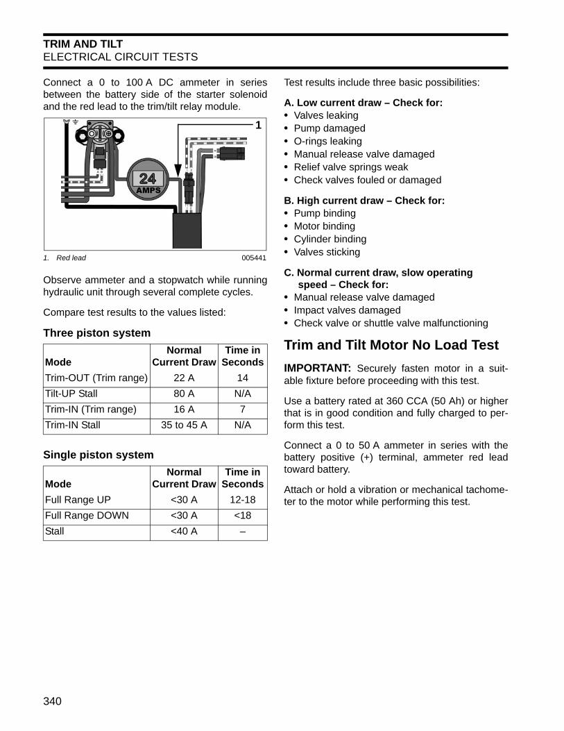
Connect a 0 to 100 A DC ammeter in seriesbetween the battery side of the starter solenoidand the red lead to the trim/tilt relay module.
Observe ammeter and a stopwatch while runninghydraulic unit through several complete cycles.
Compare test results to the values listed:
Three piston system
Single piston system
Test results include three basic possibilities:
A. Low current draw – Check for:• Valves leaking• Pump damaged• O-rings leaking• Manual release valve damaged • Relief valve springs weak• Check valves fouled or damaged
B. High current draw – Check for:• Pump binding• Motor binding• Cylinder binding• Valves sticking
C. Normal current draw, slow operating speed – Check for:• Manual release valve damaged• Impact valves damaged• Check valve or shuttle valve malfunctioning
Trim and Tilt Motor No Load Test
IMPORTANT: Securely fasten motor in a suit-able fixture before proceeding with this test.
Use a battery rated at 360 CCA (50 Ah) or higherthat is in good condition and fully charged to per-form this test.
Connect a 0 to 50 A ammeter in series with thebattery positive (+) terminal, ammeter red leadtoward battery.
Attach or hold a vibration or mechanical tachome-ter to the motor while performing this test.
1. Red lead 005441
ModeNormal
Current DrawTime in
Seconds
Trim-OUT (Trim range) 22 A 14
Tilt-UP Stall 80 A N/A
Trim-IN (Trim range) 16 A 7
Trim-IN Stall 35 to 45 A N/A
ModeNormal
Current DrawTime in
Seconds
Full Range UP <30 A 12-18
Full Range DOWN <30 A <18
Stall <40 A –
1
341
TRIM AND TILTELECTRICAL CIRCUIT TESTS
13
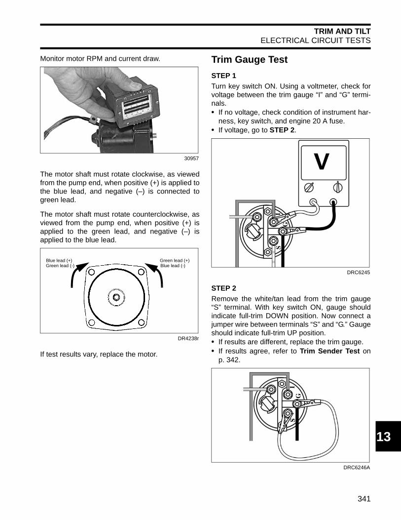
Monitor motor RPM and current draw.
The motor shaft must rotate clockwise, as viewedfrom the pump end, when positive (+) is applied tothe blue lead, and negative (–) is connected togreen lead.
The motor shaft must rotate counterclockwise, asviewed from the pump end, when positive (+) isapplied to the green lead, and negative (–) isapplied to the blue lead.
If test results vary, replace the motor.
Trim Gauge Test
STEP 1
Turn key switch ON. Using a voltmeter, check forvoltage between the trim gauge “I” and “G” termi-nals.• If no voltage, check condition of instrument har-
ness, key switch, and engine 20 A fuse.• If voltage, go to STEP 2.
STEP 2
Remove the white/tan lead from the trim gauge“S” terminal. With key switch ON, gauge shouldindicate full-trim DOWN position. Now connect ajumper wire between terminals “S” and “G.” Gaugeshould indicate full-trim UP position.• If results are different, replace the trim gauge.• If results agree, refer to Trim Sender Test on
p. 342.
30957
DR4238r
Green lead (+)Blue lead (-)
Blue lead (+)Green lead (-)
DRC6245
DRC6246A

342
TRIM AND TILTTRIM AND TILT REPLACEMENT
Trim Sender Test
IMPORTANT: To avoid immediate meter dam-age, never apply a multimeter to an electrical cir-cuit where voltage is present.
Disconnect the 3-pin connector between theinstrument harness and engine trim harness.
Connect an ohmmeter between the white/tan wire,terminal “C,” of the engine harness and a cleanengine ground.
With the outboard fully DOWN, meter must showa reading above 80 W.
With the outboard fully UP, meter must show areading below 10 W.• If results agree, refer to Trim Gauge Test on
p. 341.• If results are different, replace trim sender.
TRIM AND TILT REPLACEMENTRemovalRaise the outboard and engage the tilt support.
Remove the rubber grommet from the blue/greentrim/tilt cable connector.
Remove the terminals from the connector byusing a suitable tool to depress the tab. While thetab is depressed, pull on the wire from the rear ofthe connector to release it from the connector.
DRC6247
000686
000687

343
TRIM AND TILTTRIM AND TILT REPLACEMENT
13
Separate the trim/tilt unit wires in the braided tubeto permit removal through the hole in the sternbracket.
Remove the ground wire from the trim/tilt unit.
Remove the external snap rings from the upperpin.
Use a punch to remove the upper pin.
Retract the tilt cylinder rod.
Remove the external snap rings from the lowerpin.
Use a punch to remove the lower pin and removethe trim/tilt unit from the stern brackets.
25078
1. Ground wire 25057
25064
1
25065
25077
25076
344
TRIM AND TILTTRIM AND TILT REPLACEMENT
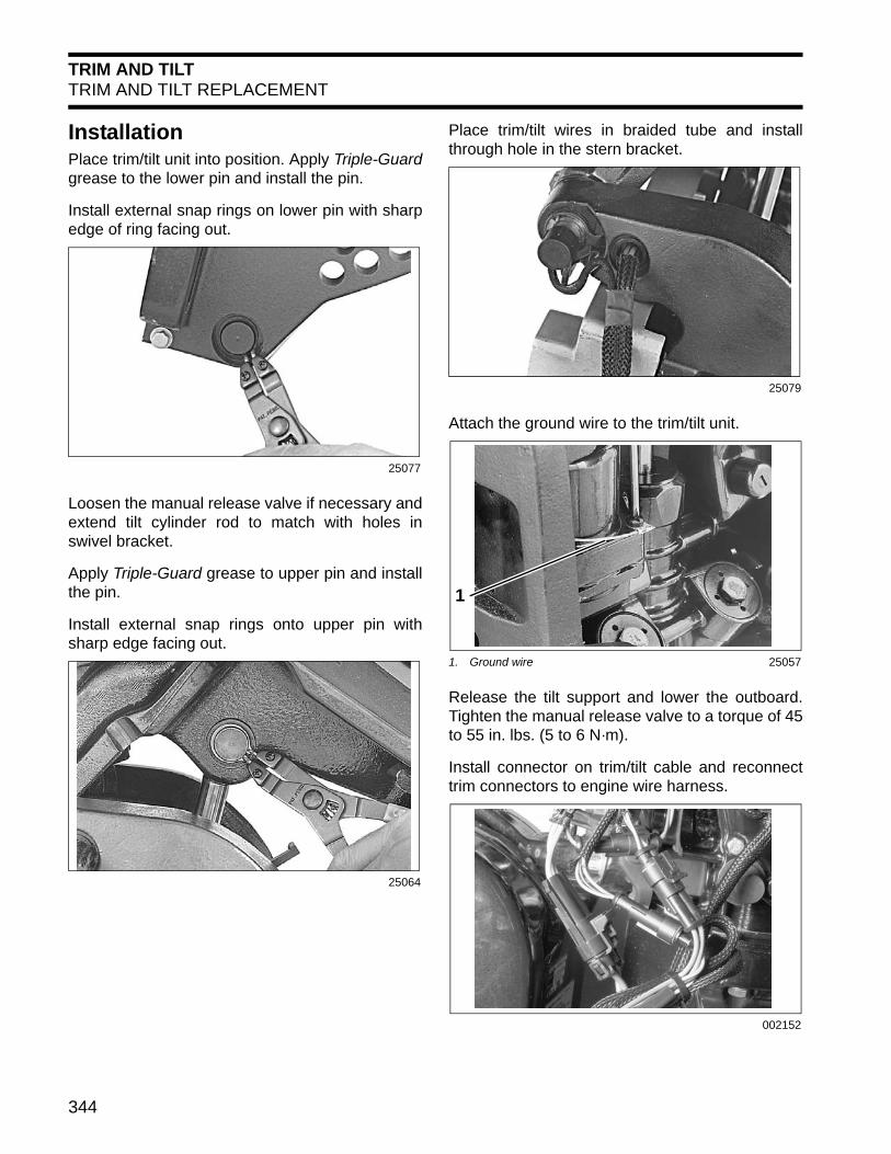
InstallationPlace trim/tilt unit into position. Apply Triple-Guardgrease to the lower pin and install the pin.
Install external snap rings on lower pin with sharpedge of ring facing out.
Loosen the manual release valve if necessary andextend tilt cylinder rod to match with holes inswivel bracket.
Apply Triple-Guard grease to upper pin and installthe pin.
Install external snap rings onto upper pin withsharp edge facing out.
Place trim/tilt wires in braided tube and installthrough hole in the stern bracket.
Attach the ground wire to the trim/tilt unit.
Release the tilt support and lower the outboard.Tighten the manual release valve to a torque of 45to 55 in. lbs. (5 to 6 N·m).
Install connector on trim/tilt cable and reconnecttrim connectors to engine wire harness.
25077
25064
25079
1. Ground wire 25057
002152
1
345
TRIM AND TILTSERVICING–SINGLE PISTON SYSTEM
13
SERVICING–SINGLE PISTON SYSTEMDisassemblyThoroughly clean the unit before disassembling.Scrub all outside surfaces with a stiff brush andhot, soapy water to prevent surface dirt from con-taminating internal parts.
Always use a lint free shop cloth when handlingpower trim/tilt components.
If painting the unit is required, paint it after it iscompletely assembled. Painting of individual com-ponents may cause flakes of paint to enter thehydraulic passages during assembly. Tape thetrim/tilt piston rods before painting.
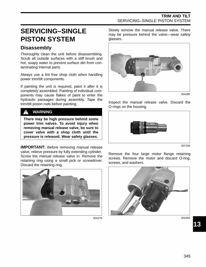
IMPORTANT: Before removing manual releasevalve, relieve pressure by fully extending cylinder.Screw the manual release valve in. Remove theretaining ring using a small pick or screwdriver.Discard the retaining ring.
Slowly remove the manual release valve. Theremay be pressure behind the valve—wear safetyglasses.
Inspect the manual release valve. Discard theO-rings on the housing.
Remove the four large motor flange retainingscrews. Remove the motor and discard O-ring,screws, and washers.
WARNING
There may be high pressure behind somepower trim valves. To avoid injury whenremoving manual release valve, be sure tocover valve with a shop cloth until thepressure is released. Wear safety glasses.
004279
004285
007108
004282

346
TRIM AND TILTSERVICING–SINGLE PISTON SYSTEM
Remove drive coupler from either the motor or thepump assembly.
Assembly
IMPORTANT: Use only Evinrude/Johnson Bio-degradable TNT Fluid to fill the hydraulic system.
Install drive coupler in pump assembly.
Install a new motor O-ring.
Position the motor on the manifold and install fournew screws and lock washers. Tighten the screws35 to 50 in. lbs. (4 to 5.6 N·m).
Oil O-rings and install them on the manual releasevalve. Oil and install the manual release valve.Tighten the valve to a torque of 45 to 55 in. lbs.(5.1 to 6.2 N·m).
Install new retaining ring in groove.
004281
004280
004282
004285
1. Retaining ring 004283
1

347
TRIM AND TILTSERVICING – THREE PISTON SYSTEM
13
Fill the oil reservoir up to the fill plug withEvinrude/Johnson Biodegradable TNT Fluid.Install the fill plug.
Run the motor, then recheck oil level. Cycle theunit several times and check the oil level when thecylinder is fully extended. Oil should be level withbottom of fill port. Install and tighten the fill plug toa torque of 45 to 55 in. lbs. (5 to 6 N·m).
SERVICING – THREE PISTON SYSTEMDisassembly
Thoroughly clean the unit before disassembling.Scrub all outside surfaces with a stiff brush andhot, soapy water to prevent surface dirt from con-taminating internal parts.
Always use a lint free shop cloth when handlingpower trim/tilt components.
If painting the unit is required, paint it after it iscompletely assembled. Painting of individual com-ponents may cause flakes of paint to enter thehydraulic passages during assembly. Tape thetrim/tilt piston rods before painting.
1. Reservoir cap 004278
1
WARNING
Before removing the manual release valve,operate the unit to the full UP position,then run the unit down momentarily andloosen the reservoir cap one full turn.
To avoid personal injury, always wear eyeprotection when servicing the hydraulicunit. Since there might be significantresidual pressure behind some compo-nents, cover each component with a shopcloth as you remove it.
CAUTION
Do not apply heat to the cylinder body orcylinders. Excessive heat can cause highpressure leaks or failure of parts.

348
TRIM AND TILTSERVICING – THREE PISTON SYSTEM
Screw the manual release valve in. Remove theretaining ring using retaining ring pliers. Removethe manual release valve.
Inspect O-ring and two plastic split rings on themanual release valve for nicks and cuts. Inspecttip of valve for damage. The two plastic split ringsare not available separately. If rings are damaged,replace the manual release valve.
Remove reservoir cap and drain the fluid into acontainer. Inspect the O-ring in the cap.
Remove the three Pozidriv screws securing thereservoir to cylinder body. Remove reservoir.
Remove the reservoir O-ring from the cylinderbody. Check machined surfaces for nicks andscratches.
Use a 6 mm hex wrench to remove the plug fromthe cylinder body. Inspect the O-ring and the filter.Replace, if necessary.
41739
1. O-ring2. Plastic split rings
22863
1. Reservoir cap 4173641751
1
2
1
41753
1. O-ring 41759
41787
1
349
TRIM AND TILTSERVICING – THREE PISTON SYSTEM
13
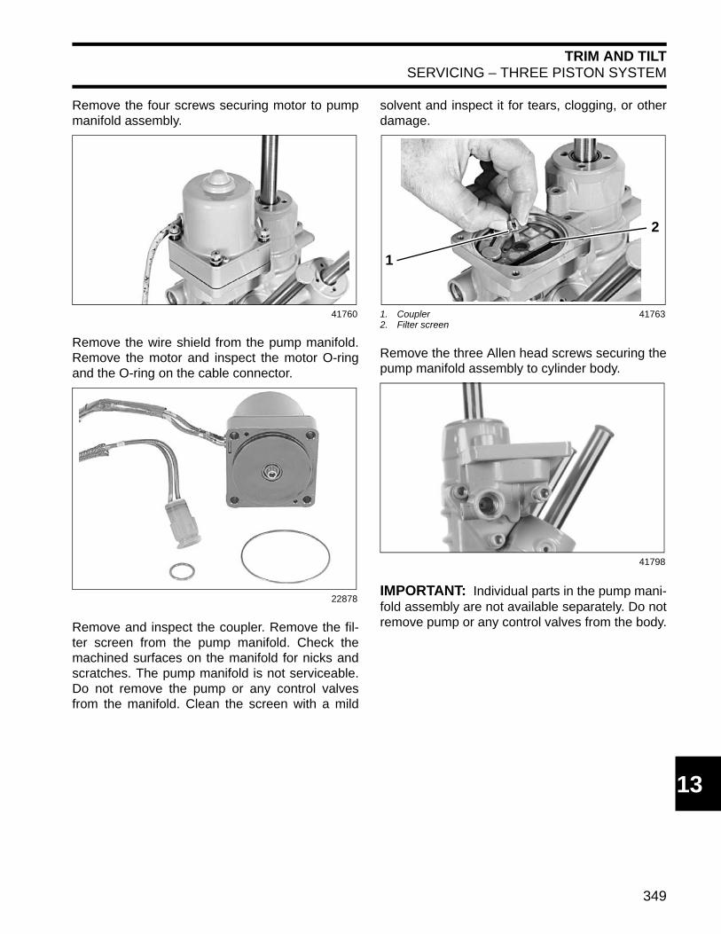
Remove the four screws securing motor to pumpmanifold assembly.
Remove the wire shield from the pump manifold.Remove the motor and inspect the motor O-ringand the O-ring on the cable connector.
Remove and inspect the coupler. Remove the fil-ter screen from the pump manifold. Check themachined surfaces on the manifold for nicks andscratches. The pump manifold is not serviceable.Do not remove the pump or any control valvesfrom the manifold. Clean the screen with a mild
solvent and inspect it for tears, clogging, or otherdamage.
Remove the three Allen head screws securing thepump manifold assembly to cylinder body.
IMPORTANT: Individual parts in the pump mani-fold assembly are not available separately. Do notremove pump or any control valves from the body.
41760
22878
1. Coupler2. Filter screen
41763
41798
2
1
350
TRIM AND TILTSERVICING – THREE PISTON SYSTEM
Remove the manifold. Remove five O-rings fromcylinder body. Check machined surfaces for nicksand scratches.
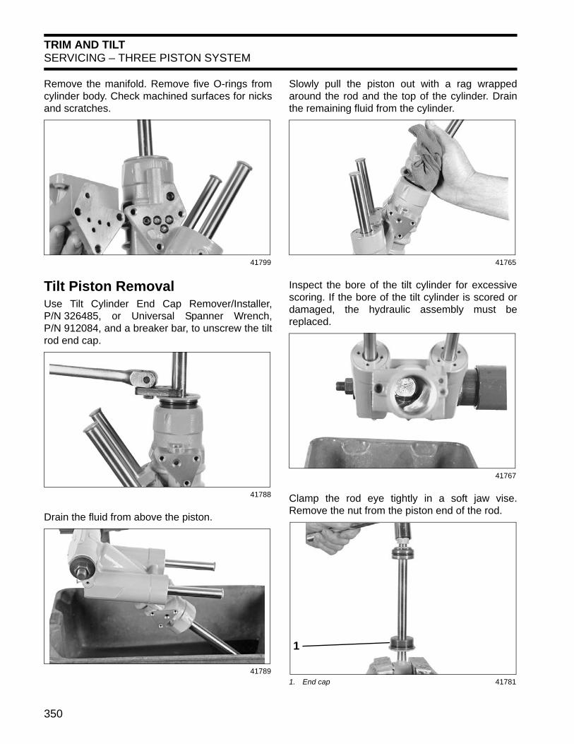
Tilt Piston RemovalUse Tilt Cylinder End Cap Remover/Installer,P/N 326485, or Universal Spanner Wrench,P/N 912084, and a breaker bar, to unscrew the tiltrod end cap.
Drain the fluid from above the piston.
Slowly pull the piston out with a rag wrappedaround the rod and the top of the cylinder. Drainthe remaining fluid from the cylinder.
Inspect the bore of the tilt cylinder for excessivescoring. If the bore of the tilt cylinder is scored ordamaged, the hydraulic assembly must bereplaced.
Clamp the rod eye tightly in a soft jaw vise.Remove the nut from the piston end of the rod.
41799
41788
41789
41765
41767
1. End cap 41781
1

351
TRIM AND TILTSERVICING – THREE PISTON SYSTEM
13
Remove the washer. Slide the tilt piston off therod. Be careful not to lose the springs, plungers,or small check valves in the piston assembly.
Remove and discard the small inner O-ring andlarge outer O-ring.
Tilt Piston Identification
Three of the four springs are one length, and thefourth spring is shorter. On assembly, the shorterspring can be positioned in any hole in the piston.
Tilt Piston AssemblyPiston check balls and plungers are identical.Lubricate and install a new outer O-ring on the tiltpiston. Place one ball, one plunger, and onespring in each hole in the piston as indicated.
Three of the four springs are one length, and thefourth spring is shorter. On assembly, the shorterspring can be positioned in any hole in the piston.Set piston aside.
41784
1. Small inner O-ring2. Large outer O-ring
41819
WARNING
Different tilt pistons are used on hydraulicunits for various outboard models. Allplungers and check balls are identical.The tilt piston assemblies contain valvingspecific to certain models. To provideimpact protection, it is important the cor-rect piston assembly be installed.
1
2
41882
41818

352
TRIM AND TILTSERVICING – THREE PISTON SYSTEM
Use a screwdriver to carefully pry the scraper outof the end cap. Discard the scraper. Remove anddiscard the large outer O-ring.
Remove and discard inner O-ring of the end cap.
Tilt Rod AssemblyClean the end cap thoroughly, then lubricate andinstall a new O-ring in the end cap. Lubricate andinstall a new scraper. The scraper is installed withthe lip facing out. Lubricate and install a newO-ring on the outside of the end cap.
Use a wire brush to clean all thread-locking mate-rial from the threads on the tilt rod.
Lubricate the inside surface of the end cap. Lubri-cate and install Tilt Cylinder Seal Protector,P/N 326005. Use a deep-well socket and a plasticmallet to drive the end cap onto the rod, thenremove the seal protector. Slide the end cap downthe tilt rod.
Remove any lubricant from the threads on the tiltrod, prime with Locquic Primer, and let dry. Slidethe piston assembly onto the tilt rod. Place a newrod O-ring over the threads.
41791
41792
1. Inner O-ring2. Lip3. Outer O-ring
41795
2
3
1
41821
1. Tilt Cylinder Seal Protector 41824
1. O-ring 41816
1
1
353
TRIM AND TILTSERVICING – THREE PISTON SYSTEM
13
Clean any thread-locking material from thethreads on the inside of the nut. Spray threads ofwith Locquic Primer and let dry. Apply a smallamount of Nut Lock to the threads. Slide thewasher over the threads and install the nut.Torque to 58 to 87 ft. lbs. (79 to 118 N·m).
To ensure that the tilt piston has been properlyassembled and the impact relief balls are properlyseated, apply Power Trim/Tilt & Steering Fluid ontop of the tilt piston. Fluid should not leak past theimpact relief balls while seated. If fluid does leak,disassemble the piston assembly and inspect therelief ball seats. Set the tilt rod assembly aside.
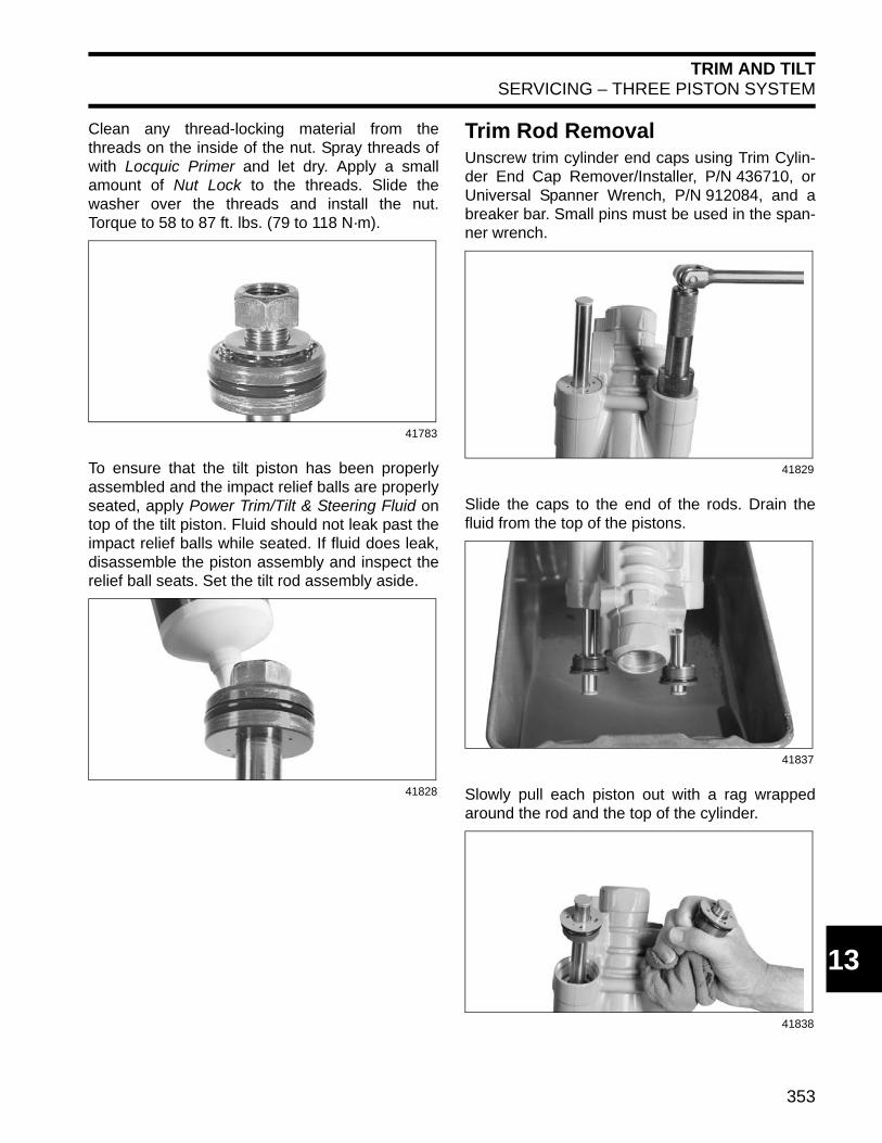
Trim Rod RemovalUnscrew trim cylinder end caps using Trim Cylin-der End Cap Remover/Installer, P/N 436710, orUniversal Spanner Wrench, P/N 912084, and abreaker bar. Small pins must be used in the span-ner wrench.
Slide the caps to the end of the rods. Drain thefluid from the top of the pistons.
Slowly pull each piston out with a rag wrappedaround the rod and the top of the cylinder.
41783
41828
41829
41837
41838
354
TRIM AND TILTSERVICING – THREE PISTON SYSTEM
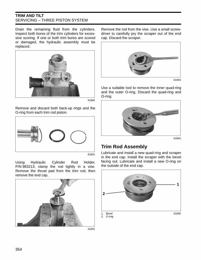
Drain the remaining fluid from the cylinders.Inspect both bores of the trim cylinders for exces-sive scoring. If one or both trim bores are scoredor damaged, the hydraulic assembly must bereplaced.
Remove and discard both back-up rings and theO-ring from each trim rod piston.
Using Hydraulic Cylinder Rod Holder,P/N 983213, clamp the rod tightly in a vise.Remove the thrust pad from the trim rod, thenremove the end cap.
Remove the rod from the vise. Use a small screw-driver to carefully pry the scraper out of the endcap. Discard the scraper.
Use a suitable tool to remove the inner quad-ringand the outer O-ring. Discard the quad-ring andO-ring.
Trim Rod AssemblyLubricate and install a new quad-ring and scraperin the end cap. Install the scraper with the bevelfacing out. Lubricate and install a new O-ring onthe outside of the end cap.
41840
41841
41842
41843
41844
1. Bevel2. O-ring
41845
1
2

355
TRIM AND TILTSERVICING – THREE PISTON SYSTEM
13
Lubricate and install a new O-ring and two newback-up rings on the trim rod piston. Place oneback-up ring on each side of the O-ring. Positionthe open end of the back-up rings 180° apart.
Using Hydraulic Cylinder Rod Holder,P/N 983213, clamp the rod tightly in a vise andlubricate the cap and rod. Slide the end cap ontothe rod and install thrust pad. Torque thrust pad 84to 108 in. lbs. (9.5 to 12 N·m).
Manifold and Reservoir InstallationLubricate five new manifold body O-rings. Placethem in the cylinder body.
Attach the valve pump assembly to the cylinderbody with three Pozidriv screws. Torque screws to60 to 84 in. lbs. (7 to 9.5 N·m).
Oil and install the manual release valve. Threadthe valve just past the snap ring groove. Do notinstall the snap ring at this time. The valve will be
1. O-ring2. Back-up rings
41847
1. Thrust pad 41848
2 1
1
41849
41850
356
TRIM AND TILTSERVICING – THREE PISTON SYSTEM
removed later for the Pressure Leakdown Teston p. 337.
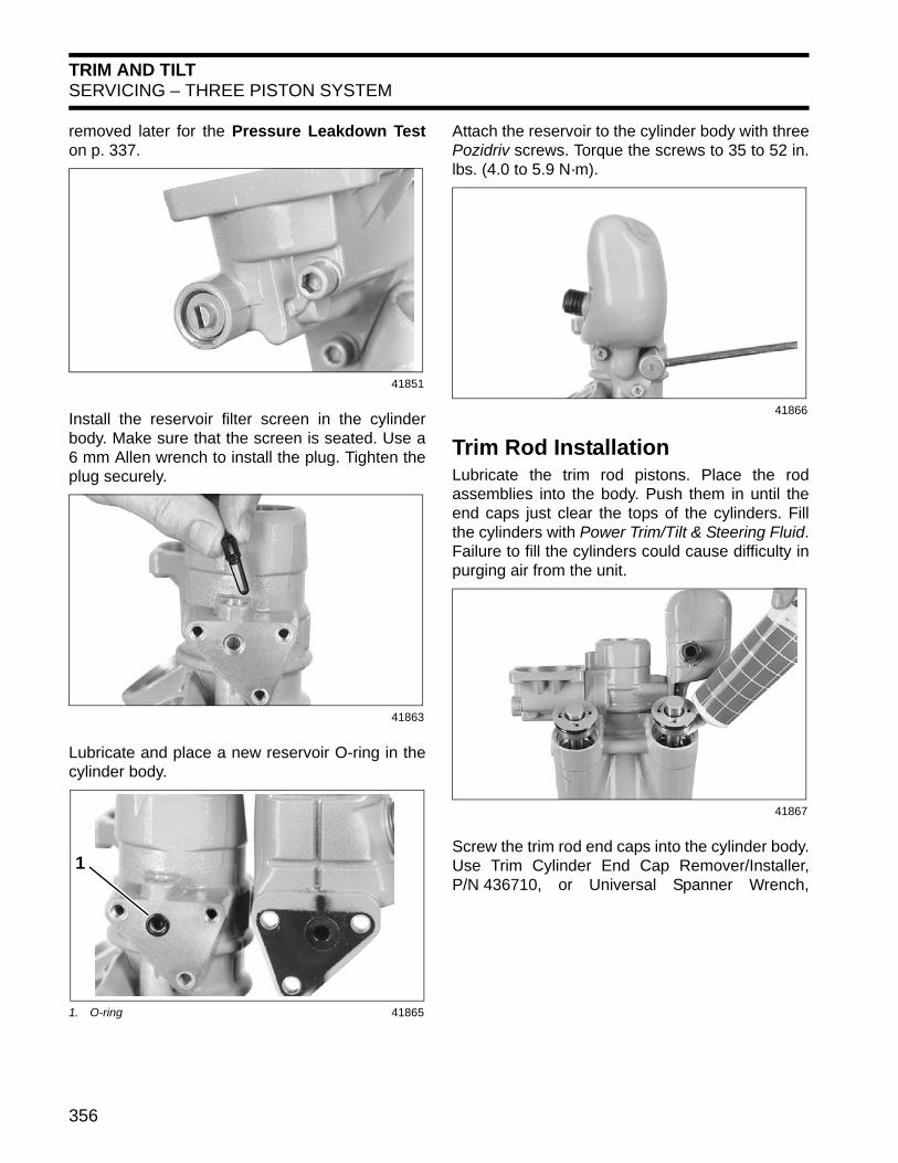
Install the reservoir filter screen in the cylinderbody. Make sure that the screen is seated. Use a6 mm Allen wrench to install the plug. Tighten theplug securely.
Lubricate and place a new reservoir O-ring in thecylinder body.
Attach the reservoir to the cylinder body with threePozidriv screws. Torque the screws to 35 to 52 in.lbs. (4.0 to 5.9 N·m).
Trim Rod InstallationLubricate the trim rod pistons. Place the rodassemblies into the body. Push them in until theend caps just clear the tops of the cylinders. Fillthe cylinders with Power Trim/Tilt & Steering Fluid.Failure to fill the cylinders could cause difficulty inpurging air from the unit.
Screw the trim rod end caps into the cylinder body.Use Trim Cylinder End Cap Remover/Installer,P/N 436710, or Universal Spanner Wrench,
41851
41863
1. O-ring 41865
1
41866
41867
357
TRIM AND TILTSERVICING – THREE PISTON SYSTEM
13
P/N 912084. Tighten caps to a torque of 60 to 70ft. lbs. (81 to 95 N·m).
Tilt Rod InstallationLubricate the tilt rod piston. Slide the end cap allthe way up on the rod assembly. Place the pistonend of the rod assembly into the cylinder body.Push it in until the end cap just clears the cylindertop. Leave enough room to pour fluid into the cyl-inder. Fill the cylinder with Power Trim/Tilt & Steer-ing Fluid. Failure to fill the cylinder could causedifficulty purging air from the unit.
Screw tilt cylinder end cap into cylinder body. UseTilt Cylinder End Cap Remover/Installer,P/N 326485, or Universal Spanner Wrench,
P/N 912084. Torque cap to 58 to 87 ft. lbs. (79 to118 N·m).
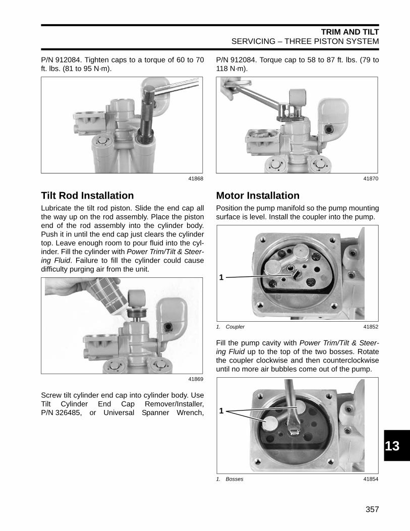
Motor InstallationPosition the pump manifold so the pump mountingsurface is level. Install the coupler into the pump.
Fill the pump cavity with Power Trim/Tilt & Steer-ing Fluid up to the top of the two bosses. Rotatethe coupler clockwise and then counterclockwiseuntil no more air bubbles come out of the pump.
41868
41869
41870
1. Coupler 41852
1. Bosses 41854
1
1
358
TRIM AND TILTSERVICING – THREE PISTON SYSTEM
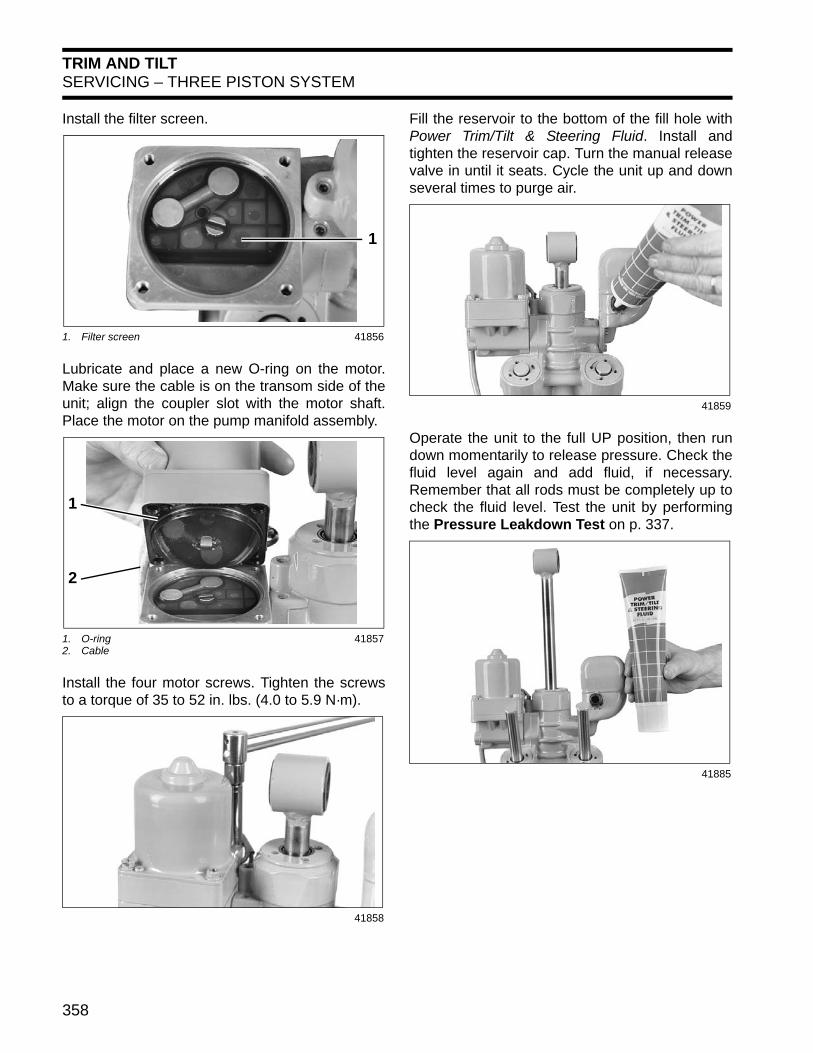
Install the filter screen.
Lubricate and place a new O-ring on the motor.Make sure the cable is on the transom side of theunit; align the coupler slot with the motor shaft.Place the motor on the pump manifold assembly.
Install the four motor screws. Tighten the screwsto a torque of 35 to 52 in. lbs. (4.0 to 5.9 N·m).
Fill the reservoir to the bottom of the fill hole withPower Trim/Tilt & Steering Fluid. Install andtighten the reservoir cap. Turn the manual releasevalve in until it seats. Cycle the unit up and downseveral times to purge air.
Operate the unit to the full UP position, then rundown momentarily to release pressure. Check thefluid level again and add fluid, if necessary.Remember that all rods must be completely up tocheck the fluid level. Test the unit by performingthe Pressure Leakdown Test on p. 337.
1. Filter screen 41856
1. O-ring2. Cable
41857
41858
1
1
2
41859
41885
359
TRIM AND TILTSERVICING – THREE PISTON SYSTEM
13
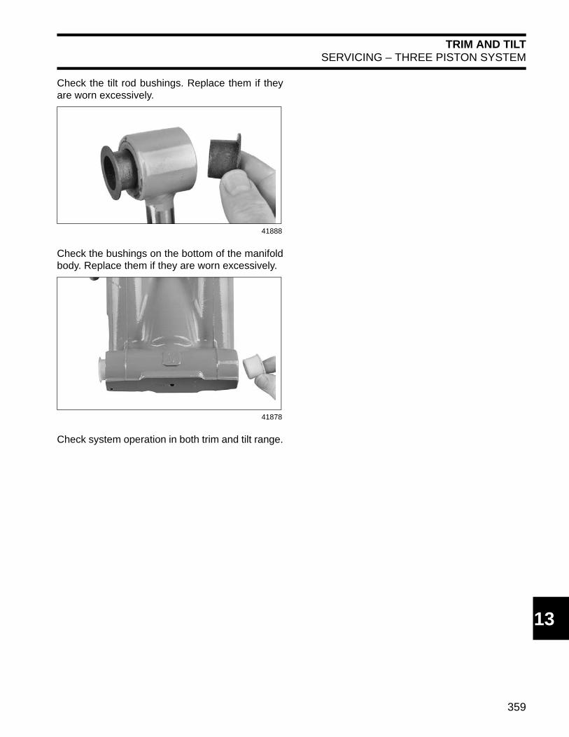
Check the tilt rod bushings. Replace them if theyare worn excessively.
Check the bushings on the bottom of the manifoldbody. Replace them if they are worn excessively.
Check system operation in both trim and tilt range.
41888
41878