exposure of polymer film thermal control materials on the ... · exposure of polymer film thermal...
TRANSCRIPT
Joyce Dever and Sharon MillerGlenn Research Center, Cleveland, Ohio
Russell Messer and Edward SechkarQSS Group, Inc., Cleveland, Ohio
Greg TollisCleveland State University, Cleveland, Ohio
Exposure of Polymer Film Thermal ControlMaterials on the Materials InternationalSpace Station Experiment (MISSE)
NASA/TM—2002-211363
February 2002
AIAA–2001–4924
https://ntrs.nasa.gov/search.jsp?R=20020038542 2018-07-07T18:20:00+00:00Z
The NASA STI Program Office . . . in Profile
Since its founding, NASA has been dedicated tothe advancement of aeronautics and spacescience. The NASA Scientific and TechnicalInformation (STI) Program Office plays a key partin helping NASA maintain this important role.
The NASA STI Program Office is operated byLangley Research Center, the Lead Center forNASA’s scientific and technical information. TheNASA STI Program Office provides access to theNASA STI Database, the largest collection ofaeronautical and space science STI in the world.The Program Office is also NASA’s institutionalmechanism for disseminating the results of itsresearch and development activities. These resultsare published by NASA in the NASA STI ReportSeries, which includes the following report types:
• TECHNICAL PUBLICATION. Reports ofcompleted research or a major significantphase of research that present the results ofNASA programs and include extensive dataor theoretical analysis. Includes compilationsof significant scientific and technical data andinformation deemed to be of continuingreference value. NASA’s counterpart of peer-reviewed formal professional papers buthas less stringent limitations on manuscriptlength and extent of graphic presentations.
• TECHNICAL MEMORANDUM. Scientificand technical findings that are preliminary orof specialized interest, e.g., quick releasereports, working papers, and bibliographiesthat contain minimal annotation. Does notcontain extensive analysis.
• CONTRACTOR REPORT. Scientific andtechnical findings by NASA-sponsoredcontractors and grantees.
• CONFERENCE PUBLICATION. Collectedpapers from scientific and technicalconferences, symposia, seminars, or othermeetings sponsored or cosponsored byNASA.
• SPECIAL PUBLICATION. Scientific,technical, or historical information fromNASA programs, projects, and missions,often concerned with subjects havingsubstantial public interest.
• TECHNICAL TRANSLATION. English-language translations of foreign scientificand technical material pertinent to NASA’smission.
Specialized services that complement the STIProgram Office’s diverse offerings includecreating custom thesauri, building customizeddata bases, organizing and publishing researchresults . . . even providing videos.
For more information about the NASA STIProgram Office, see the following:
• Access the NASA STI Program Home Pageat http://www.sti.nasa.gov
• E-mail your question via the Internet [email protected]
• Fax your question to the NASA AccessHelp Desk at 301–621–0134
• Telephone the NASA Access Help Desk at301–621–0390
• Write to: NASA Access Help Desk NASA Center for AeroSpace Information 7121 Standard Drive Hanover, MD 21076

Joyce Dever and Sharon MillerGlenn Research Center, Cleveland, Ohio
Russell Messer and Edward SechkarQSS Group, Inc., Cleveland, Ohio
Greg TollisCleveland State University, Cleveland, Ohio
Exposure of Polymer Film Thermal ControlMaterials on the Materials InternationalSpace Station Experiment (MISSE)
NASA/TM—2002-211363
February 2002
National Aeronautics andSpace Administration
Glenn Research Center
Prepared for theInternational Space Station Utilization—2001sponsored by the American Institute of Aeronautics and AstronauticsCape Canaveral, Florida, October 15–18, 2001
AIAA–2001–4924
Acknowledgments
The authors gratefully acknowledge the contributions of Don Jaworske, Bruce Banks, andKim de Groh (NASA GRC), Eve Wooldridge and Charles Powers (NASA Goddard Space Flight Center),
and Wanda Peters (Swales Aerospace). We also thank the MISSE Project Office and Boeingfor providing us the opportunity to be a part of MISSE.
Available from
NASA Center for Aerospace Information7121 Standard DriveHanover, MD 21076
National Technical Information Service5285 Port Royal RoadSpringfield, VA 22100
Trade names or manufacturers’ names are used in this report foridentification only. This usage does not constitute an officialendorsement, either expressed or implied, by the National
Aeronautics and Space Administration.
Available electronically at http://gltrs.grc.nasa.gov/GLTRS
NASA/TM2002-211363 1
EXPOSURE OF POLYMER FILM THERMAL CONTROL MATERIALS ON THE MATERIALS INTERNATIONAL SPACE STATION EXPERIMENT (MISSE)
Joyce Dever and Sharon Miller
National Aeronautics and Space Administration Glenn Research Center Cleveland, Ohio 44135
Russell Messer and Edward Sechkar
QSS Group, Inc. Cleveland, Ohio 44135
Greg Tollis
Cleveland State University Cleveland, Ohio 44115
Abstract Seventy-nine samples of polymer film thermal control (PFTC) materials have been provided by the National Aeronautics and Space Administration (NASA) Glenn Research Center (GRC) for exposure to the low Earth orbit environment on the exterior of the International Space Station (ISS) as part of the Materials International Space Station Experiment (MISSE). MISSE is a materials flight experiment sponsored by the Air Force Research Lab/Materials Lab and NASA. This paper will describe background, objectives, and configurations for the GRC PFTC samples for MISSE. These samples include polyimides, fluorinated polyimides, and Teflon fluorinated ethylene propylene (FEP) with and without second-surface metalizing layers and/or surface coatings. Also included are polyphenylene benzobisoxazole (PBO) and a polyarylene ether benzimidazole (TOR-LMTM). On August 16, 2001, astronauts installed passive experiment carriers (PECs) on the exterior of the ISS in which were located twenty-eight of the GRC PFTC samples for 1-year space exposure. MISSE PECs for 3-year exposure, which will contain fifty-one GRC PFTC samples, will be installed on the ISS at a later date. Once returned from the ISS, MISSE GRC PFTC samples will be examined for changes in optical and mechanical properties and atomic oxygen (AO) erosion. Additional sapphire witness samples located on the AO exposed trays will be examined for deposition of contaminants.
Introduction Polymer materials commonly used for spacecraft thermal control can experience degradation in optical and mechanical properties due to long duration exposure in the space environment.1,2 Teflon FEP (fluorinated ethylene propylene), a common thermal control material, has been observed to become brittle upon long-term space exposure on the Hubble Space Telescope (HST).2 Space environmental effects that can cause damage to polymers include solar ultraviolet radiation, solar flare x-rays, solar wind electrons and protons trapped in Earth’s magnetic field, temperature effects, and low Earth orbit AO. Spacecraft surfaces may experience significant temperature excursions during each orbit due to the transitions of the spacecraft between sunlight and shadow. Temperature cycling through the glass transition temperature range has been shown to degrade the mechanical properties of polymers such as Teflon FEP.3 Ultraviolet radiation can damage polymers by breaking chemical bonds, thereby changing the polymer structure.4,5 Polymers can experience degradation in mechanical properties upon exposure to radiation.3,5 Atomic oxygen reacts chemically with polymeric materials causing oxidation and erosion.4, 5 It is obvious that a variety of synergistic effects are also possible with this combination of environmental exposure conditions. While typical polymer film thickness for spacecraft multi-layer insulation MLI ranges between 50 and
NASA/TM2002-211363 2
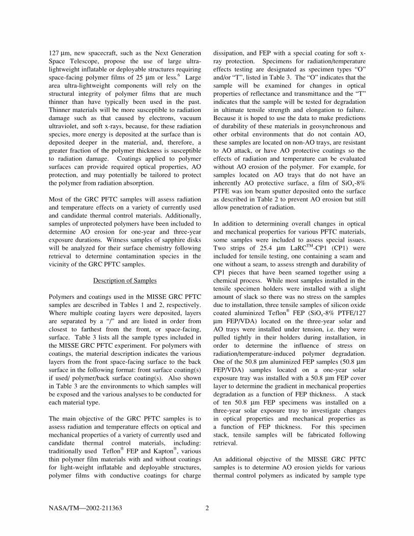
127 µm, new spacecraft, such as the Next Generation Space Telescope, propose the use of large ultra-lightweight inflatable or deployable structures requiring space-facing polymer films of 25 µm or less.6 Large area ultra-lightweight components will rely on the structural integrity of polymer films that are much thinner than have typically been used in the past. Thinner materials will be more susceptible to radiation damage such as that caused by electrons, vacuum ultraviolet, and soft x-rays, because, for these radiation species, more energy is deposited at the surface than is deposited deeper in the material, and, therefore, a greater fraction of the polymer thickness is susceptible to radiation damage. Coatings applied to polymer surfaces can provide required optical properties, AO protection, and may potentially be tailored to protect the polymer from radiation absorption. Most of the GRC PFTC samples will assess radiation and temperature effects on a variety of currently used and candidate thermal control materials. Additionally, samples of unprotected polymers have been included to determine AO erosion for one-year and three-year exposure durations. Witness samples of sapphire disks will be analyzed for their surface chemistry following retrieval to determine contamination species in the vicinity of the GRC PFTC samples.
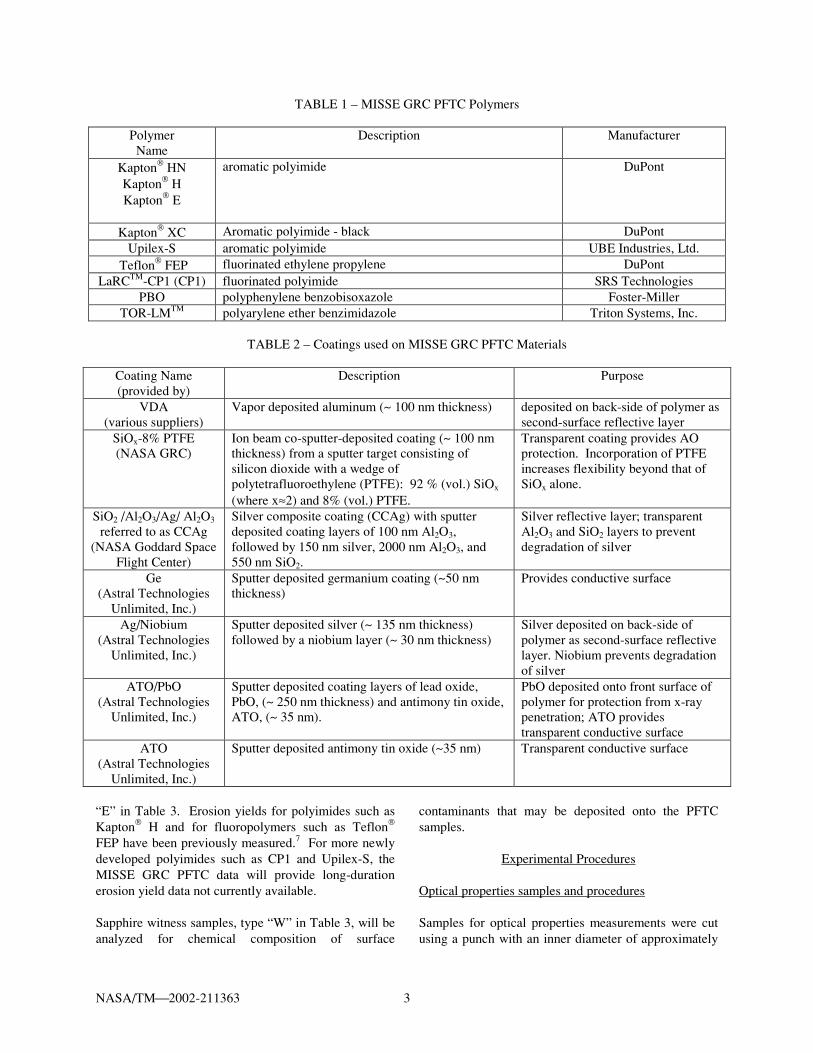
Description of Samples Polymers and coatings used in the MISSE GRC PFTC samples are described in Tables 1 and 2, respectively. Where multiple coating layers were deposited, layers are separated by a “/” and are listed in order from closest to farthest from the front, or space-facing, surface. Table 3 lists all the sample types included in the MISSE GRC PFTC experiment. For polymers with coatings, the material description indicates the various layers from the front space-facing surface to the back surface in the following format: front surface coating(s) if used/ polymer/back surface coating(s). Also shown in Table 3 are the environments to which samples will be exposed and the various analyses to be conducted for each material type. The main objective of the GRC PFTC samples is to assess radiation and temperature effects on optical and mechanical properties of a variety of currently used and candidate thermal control materials, including: traditionally used Teflon FEP and Kapton, various thin polymer film materials with and without coatings for light-weight inflatable and deployable structures, polymer films with conductive coatings for charge
dissipation, and FEP with a special coating for soft x-ray protection. Specimens for radiation/temperature effects testing are designated as specimen types “O” and/or “T”, listed in Table 3. The “O” indicates that the sample will be examined for changes in optical properties of reflectance and transmittance and the “T” indicates that the sample will be tested for degradation in ultimate tensile strength and elongation to failure. Because it is hoped to use the data to make predictions of durability of these materials in geosynchronous and other orbital environments that do not contain AO, these samples are located on non-AO trays, are resistant to AO attack, or have AO protective coatings so the effects of radiation and temperature can be evaluated without AO erosion of the polymer. For example, for samples located on AO trays that do not have an inherently AO protective surface, a film of SiOx-8% PTFE was ion beam sputter deposited onto the surface as described in Table 2 to prevent AO erosion but still allow penetration of radiation. In addition to determining overall changes in optical and mechanical properties for various PFTC materials, some samples were included to assess special issues. Two strips of 25.4 µm LaRCTM-CP1 (CP1) were included for tensile testing, one containing a seam and one without a seam, to assess strength and durability of CP1 pieces that have been seamed together using a chemical process. While most samples installed in the tensile specimen holders were installed with a slight amount of slack so there was no stress on the samples due to installation, three tensile samples of silicon oxide coated aluminized Teflon FEP (SiOx-8% PTFE/127 µm FEP/VDA) located on the three-year solar and AO trays were installed under tension, i.e. they were pulled tightly in their holders during installation, in order to determine the influence of stress on radiation/temperature-induced polymer degradation. One of the 50.8 µm aluminized FEP samples (50.8 µm FEP/VDA) samples located on a one-year solar exposure tray was installed with a 50.8 µm FEP cover layer to determine the gradient in mechanical properties degradation as a function of FEP thickness. A stack of ten 50.8 µm FEP specimens was installed on a three-year solar exposure tray to investigate changes in optical properties and mechanical properties as a function of FEP thickness. For this specimen stack, tensile samples will be fabricated following retrieval. An additional objective of the MISSE GRC PFTC samples is to determine AO erosion yields for various thermal control polymers as indicated by sample type
NASA/TM2002-211363 3
TABLE 1 – MISSE GRC PFTC Polymers
Polymer Name
Description Manufacturer
Kapton HN Kapton H Kapton E
aromatic polyimide DuPont
Kapton XC Aromatic polyimide - black DuPont Upilex-S aromatic polyimide UBE Industries, Ltd.
Teflon FEP fluorinated ethylene propylene DuPont LaRCTM-CP1 (CP1) fluorinated polyimide SRS Technologies
PBO polyphenylene benzobisoxazole Foster-Miller TOR-LMTM polyarylene ether benzimidazole Triton Systems, Inc.
TABLE 2 – Coatings used on MISSE GRC PFTC Materials
Coating Name (provided by)
Description Purpose
VDA (various suppliers)
Vapor deposited aluminum (~ 100 nm thickness) deposited on back-side of polymer as second-surface reflective layer
SiOx-8% PTFE (NASA GRC)
Ion beam co-sputter-deposited coating (~ 100 nm thickness) from a sputter target consisting of silicon dioxide with a wedge of polytetrafluoroethylene (PTFE): 92 % (vol.) SiOx (where x≈2) and 8% (vol.) PTFE.
Transparent coating provides AO protection. Incorporation of PTFE increases flexibility beyond that of SiOx alone.
SiO2 /Al2O3/Ag/ Al2O3 referred to as CCAg
(NASA Goddard Space Flight Center)
Silver composite coating (CCAg) with sputter deposited coating layers of 100 nm Al2O3, followed by 150 nm silver, 2000 nm Al2O3, and 550 nm SiO2.
Silver reflective layer; transparent Al2O3 and SiO2 layers to prevent degradation of silver
Ge (Astral Technologies
Unlimited, Inc.)
Sputter deposited germanium coating (~50 nm thickness)
Provides conductive surface
Ag/Niobium (Astral Technologies
Unlimited, Inc.)
Sputter deposited silver (~ 135 nm thickness) followed by a niobium layer (~ 30 nm thickness)
Silver deposited on back-side of polymer as second-surface reflective layer. Niobium prevents degradation of silver
ATO/PbO (Astral Technologies
Unlimited, Inc.)
Sputter deposited coating layers of lead oxide, PbO, (~ 250 nm thickness) and antimony tin oxide, ATO, (~ 35 nm).
PbO deposited onto front surface of polymer for protection from x-ray penetration; ATO provides transparent conductive surface
ATO (Astral Technologies
Unlimited, Inc.)
Sputter deposited antimony tin oxide (~35 nm) Transparent conductive surface
“E” in Table 3. Erosion yields for polyimides such as Kapton H and for fluoropolymers such as Teflon FEP have been previously measured.7 For more newly developed polyimides such as CP1 and Upilex-S, the MISSE GRC PFTC data will provide long-duration erosion yield data not currently available. Sapphire witness samples, type “W” in Table 3, will be analyzed for chemical composition of surface
contaminants that may be deposited onto the PFTC samples.
Experimental Procedures Optical properties samples and procedures Samples for optical properties measurements were cut using a punch with an inner diameter of approximately
NASA/TM2002-211363 4
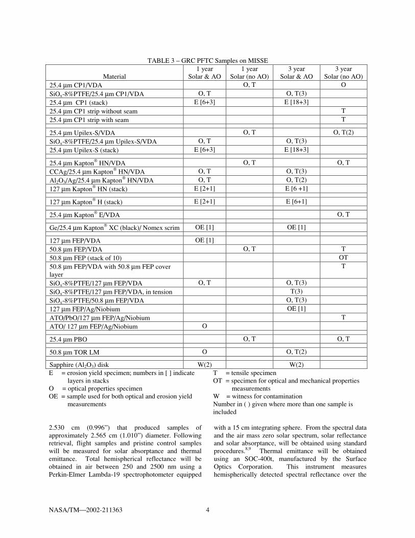
TABLE 3 – GRC PFTC Samples on MISSE
Material
1 year Solar & AO
1 year Solar (no AO)
3 year Solar & AO
3 year Solar (no AO)
25.4 µm CP1/VDA O, T O SiOx-8%PTFE/25.4 µm CP1/VDA O, T O, T(3) 25.4 µm CP1 (stack) E [6+3] E [18+3] 25.4 µm CP1 strip without seam T 25.4 µm CP1 strip with seam T
25.4 µm Upilex-S/VDA O, T O, T(2) SiOx-8%PTFE/25.4 µm Upilex-S/VDA O, T O, T(3) 25.4 µm Upilex-S (stack) E [6+3] E [18+3]
25.4 µm Kapton HN/VDA O, T O, T CCAg/25.4 µm Kapton HN/VDA O, T O, T(3) Al2O3/Ag/25.4 µm Kapton HN/VDA O, T O, T(2) 127 µm Kapton HN (stack) E [2+1] E [6 +1]
127 µm Kapton H (stack) E [2+1] E [6+1]
25.4 µm Kapton E/VDA O, T
Ge/25.4 µm Kapton XC (black)/ Nomex scrim OE [1] OE [1]
127 µm FEP/VDA OE [1] 50.8 µm FEP/VDA O, T T 50.8 µm FEP (stack of 10) OT 50.8 µm FEP/VDA with 50.8 µm FEP cover layer
T
SiOx-8%PTFE/127 µm FEP/VDA O, T O, T(3) SiOx-8%PTFE/127 µm FEP/VDA, in tension T(3) SiOx-8%PTFE/50.8 µm FEP/VDA O, T(3) 127 µm FEP/Ag/Niobium OE [1] ATO/PbO/127 µm FEP/Ag/Niobium T ATO/ 127 µm FEP/Ag/Niobium O
25.4 µm PBO O, T O, T
50.8 µm TOR LM O O, T(2)
Sapphire (Al2O3) disk W(2) W(2) E = erosion yield specimen; numbers in [ ] indicate layers in stacks O = optical properties specimen OE = sample used for both optical and erosion yield measurements
T = tensile specimen OT = specimen for optical and mechanical properties measurements W = witness for contamination Number in ( ) given where more than one sample is included
2.530 cm (0.996”) that produced samples of approximately 2.565 cm (1.010”) diameter. Following retrieval, flight samples and pristine control samples will be measured for solar absorptance and thermal emittance. Total hemispherical reflectance will be obtained in air between 250 and 2500 nm using a Perkin-Elmer Lambda-19 spectrophotometer equipped
with a 15 cm integrating sphere. From the spectral data and the air mass zero solar spectrum, solar reflectance and solar absorptance, will be obtained using standard procedures.8,9 Thermal emittance will be obtained using an SOC-400t, manufactured by the Surface Optics Corporation. This instrument measures hemispherically detected spectral reflectance over the
NASA/TM2002-211363 5
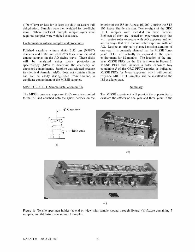
wavelength range 2-25 µm.10 Using standard calculations, room temperature hemispherical emittance will be obtained from the spectral data and the room temperature blackbody distribution.9 Tensile test samples and procedures Tensile test samples were fabricated using an ASTM D-638 Type V (five) specimen die.11 This dog-bone shaped die provides the smallest specimen size per this ASTM standard with a gage length of 7.62 mm, and a gage width of 3.18 mm. In order to occupy the least area possible on the MISSE carriers, tensile specimen holders were designed and fabricated to allow the gage area of samples to receive full space exposure while the grip ends are wrapped through the sample holder fixture and secured underneath the exposed gage area. Figure 1(a) shows an end-on view of a sample loaded in the tensile specimen holder. In order to have enough sample length to grip the ends once the sample was wound through the holder, the tensile specimen die was used so that it did not cut through the grip ends in order to make samples longer than the length of the die. Whereas the tensile die produces samples 6.35 cm long, a 5.08 cm long plastic cutting board was used so that the die did not cut the grip ends. The grip ends were then cut to a longer length than provided by the die to produce samples 12.7 cm in length with 7.62 cm to one side of center and 5.08 cm to the other. Once tensile samples were loaded into the holders, excess grip ends were trimmed. Tensile holders for 5 and for 11 tensile specimens, shown in Figures 1b and 1c, respectively, were fabricated to fit available areas on the MISSE carriers. The 5-specimen holder occupies an area of 2.54 cm x 10.16 cm and the 11-specimen holder occupies an area of 2.54 cm x 17.78 cm. Following retrieval, a bench-top tensile tester will be used to test MISSE-flown samples along with pristine control samples according to ASTM D-638 to obtain load-displacement data, stress-strain curves, ultimate tensile strength, and elongation to failure. Erosion yield samples and procedures Samples for erosion yield were cut using a punch with an inner diameter of approximately 2.530 cm (0.996”) that produced samples of approximately 2.565 cm (1.010”) diameter. The equation for calculation of erosion yield is given in equation (1):
EFA
m=
∆ρ
(1)
where
∆m = mass loss (g) A = exposure area (cm2) ρ = material density (g/cm3) F = atomic oxygen fluence (atoms/cm2) E = erosion yield (cm3/atom) To calculate erosion yield for the MISSE samples, pre-flight and post-flight mass measurements will be used along with the known sample exposure area, polymer density, and calculations of AO fluence as shown in equation (1). Atomic oxygen fluences for the expected MISSE conditions at a 400 km circular orbit, 51.6-degree inclination, and a mission start date of June 2001 have been calculated to be 3.28x10²¹ atoms/cm2 for 1 year, 4.55x10²¹ atoms/cm2 for 1.5 years, and 7.40x10²¹ atoms/cm2 for 3 years. These estimates will be revised based on changes in the actual MISSE mission dates. For example, the 1-year carriers were not actually deployed until August 2001, and the 3-year carriers will be deployed at a later date. In order to assure enough sample thickness to last for the MISSE mission durations, estimates of past space flight erosion yield measurements were used, and contingency thickness was added. For polyimide samples Kapton H, Kapton HN, Upilex-S and fluorinated polyimide CP1, erosion yield estimates for MISSE were based on previous space flight characterization of Kapton H whose erosion yield was determined to be 3x10-24 cm3/atom.7 Because of the multitude of data points previously obtained for Kapton H (Ref. 7), it will serve as a witness sample for comparison of erosion yields for the other materials being tested. For FEP samples, the erosion yield estimate was 0.337x10⁻²⁴ cm3/atom based on space flight characterization from the Long Duration Exposure Facility.7 These erosion yield values were used along with the estimated AO fluence for the ISS environment of 3.28x10²¹ atoms/cm2 for a one-year exposure duration in order to determine the sample thickness required for one year and three year exposures. Table 3 indicates the number of layers included for stacked erosion yield samples. Two stacks were separately weighed as indicated by the following convention: [number in top stack + number in underlying stack]. The top stacks provide enough thickness for a minimum of 1.5 years of exposure for 1-year trays and 4.5 years of exposure for 3-year trays to allow contingency in the event of late retrieval. The underlying stacks provide thickness to last at least 9 additional months. Use of separately weighed stacks allows for greater sensitivity in the mass measurements, as the underlying layers do not need to be weighed if they are not eroded. Erosion yield samples were placed in vacuum desiccators at a pressure of approximately 13.3 Pa
NASA/TM2002-211363 6
(100 mTorr) or less for at least six days to assure full dehydration. Samples were then weighed for pre-flight mass. Where stacks of multiple sample layers were required, samples were weighed as a stack. Contamination witness samples and procedures Polished sapphire witness disks 2.52 cm (0.993”) diameter and 1.588 mm (0.0625”) thick were included among samples on the AO facing trays. These disks will be analyzed using x-ray photoelectron spectroscopy (XPS) to determine the chemistry of deposited contaminants. Sapphire was selected because its chemical formula, Al2O3, does not contain silicon and can be easily distinguished from silicone, a candidate contaminant of the MISSE samples. MISSE GRC PFTC Sample Installation on ISS The MISSE one-year exposure PECs were transported to the ISS and attached onto the Quest Airlock on the
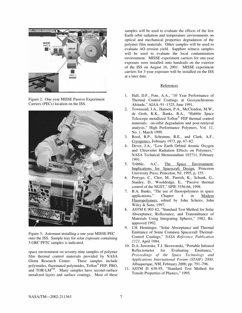
exterior of the ISS on August 16, 2001, during the STS 105 Space Shuttle mission. Twenty-eight of the GRC PFTC samples were included on these carriers. Eighteen of them are located on experiment trays that will receive solar exposure with AO exposure and ten are on trays that will receive solar exposure with no AO. Despite an originally planned mission duration of one year, it is currently planned that the MISSE “one-year” PECs will actually be exposed to the space environment for 18 months. The location of the one-year MISSE PECs on the ISS is shown in Figure 2. MISSE PECs that includes a solar exposure tray containing 5 of the GRC PFTC samples as indicated. MISSE PECs for 3-year exposure, which will contain fifty-one GRC PFTC samples, will be installed on the ISS at a later date.
Summary The MISSE experiment will provide the opportunity to evaluate the effects of one year and three years in the
(a) (b)
(c)
Figure 1: Tensile specimen holder (a) end on view with sample wound through fixture, (b) fixture containing 5 samples, and (b) fixture containing 11 samples.
C Gage area
Both ends
L
NASA/TM2002-211363 7
Figure 2: One-year MISSE Passive Experiment Carriers (PECs) location on the ISS.
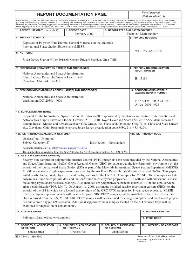
Figure 3: Astronaut installing a one-year MISSE PEC onto the ISS. Sample tray for solar exposure containing 5 GRC PFTC samples is indicated. space environment on seventy-nine samples of polymer film thermal control materials provided by NASA Glenn Research Center. These samples include polyimides, fluorinated polyimides, Teflon FEP, PBO, and TOR-LMTM. Many samples have second-surface metalized layers and surface coatings. Most of these
samples will be used to evaluate the effects of the low Earth orbit radiation and temperature environments on optical and mechanical properties degradation of the polymer film materials. Other samples will be used to evaluate AO erosion yield. Sapphire witness samples will be used to evaluate the local contamination environment. MISSE experiment carriers for one-year exposure were installed onto handrails on the exterior of the ISS on August 16, 2001. MISSE experiment carriers for 3-year exposure will be installed on the ISS at a later date.
References 1. Hall, D.F., Fote, A.A., “10 Year Performance of
Thermal Control Coatings at Geosynchronous Altitude,” AIAA–91–1325, June 1991.
2. Townsend, J.A., Hansen, P.A., McClendon, M.W., de Groh, K.K., Banks, B.A., “Hubble Space Telescope metallized Teflon FEP thermal control materials: on-orbit degradation and post-retrieval analysis,” High Performance Polymers, Vol. 11, No. 1, March 1999.
3. Reed, R.P., Schramm, R.E., and Clark, A.F., Cryogenics, February 1973, pp. 67–82.
4. Dever, J.A., “Low Earth Orbital Atomic Oxygen and Ultraviolet Radiation Effects on Polymers,” NASA Technical Memorandum 103711, February 1991.
5. Tribble, A.C., The Space Environment: Implications for Spacecraft Design, Princeton University Press, Princeton, NJ, 1995, p. 155.
6. Perrygo, C., Choi, M., Parrish, K., Schunk, G., Stanley, D., Wooldridge, E., “Passive thermal control of the NGST,” SPIE 3356-66, 1998.
7. B.A. Banks, “The use of fluoropolymers in space applications,” Chapter 4 in Modern Fluoropolymers, edited by John Scheirs, John Wiley & Sons, 1997.
8. ASTM E 903-82, “Standard Test Method for Solar Absorptance, Reflectance, and Transmittance of Materials Using Integrating Spheres,” 1982, Re-approved 1992.
9. J.H. Henninger, “Solar Absorptance and Thermal Emittance of Some Common Spacecraft Thermal-Control Coatings,” NASA Reference Publication 1121, April 1984.
10. D.A. Jaworske, T.J. Skowronski, “Portable Infrared Reflectometer for Evaluating Emittance,” Proceedings of the Space Technology and Applications International Forum (STAIF) 2000, Albuquerque, NM, February 2000, pp. 791–796.
11. ASTM D 638-95, “Standard Test Method for Tensile Properties of Plastics,” 1995.
This publication is available from the NASA Center for AeroSpace Information, 301–621–0390.
REPORT DOCUMENTATION PAGE
2. REPORT DATE
19. SECURITY CLASSIFICATION OF ABSTRACT
18. SECURITY CLASSIFICATION OF THIS PAGE
Public reporting burden for this collection of information is estimated to average 1 hour per response, including the time for reviewing instructions, searching existing data sources,gathering and maintaining the data needed, and completing and reviewing the collection of information. Send comments regarding this burden estimate or any other aspect of thiscollection of information, including suggestions for reducing this burden, to Washington Headquarters Services, Directorate for Information Operations and Reports, 1215 JeffersonDavis Highway, Suite 1204, Arlington, VA 22202-4302, and to the Office of Management and Budget, Paperwork Reduction Project (0704-0188), Washington, DC 20503.
NSN 7540-01-280-5500 Standard Form 298 (Rev. 2-89)Prescribed by ANSI Std. Z39-18298-102
Form Approved
OMB No. 0704-0188
12b. DISTRIBUTION CODE
8. PERFORMING ORGANIZATION REPORT NUMBER
5. FUNDING NUMBERS
3. REPORT TYPE AND DATES COVERED
4. TITLE AND SUBTITLE
6. AUTHOR(S)
7. PERFORMING ORGANIZATION NAME(S) AND ADDRESS(ES)
11. SUPPLEMENTARY NOTES
12a. DISTRIBUTION/AVAILABILITY STATEMENT
13. ABSTRACT (Maximum 200 words)
14. SUBJECT TERMS
17. SECURITY CLASSIFICATION OF REPORT
16. PRICE CODE
15. NUMBER OF PAGES
20. LIMITATION OF ABSTRACT
Unclassified Unclassified
Technical Memorandum
Unclassified
National Aeronautics and Space AdministrationJohn H. Glenn Research Center at Lewis FieldCleveland, Ohio 44135–3191
1. AGENCY USE ONLY (Leave blank)
10. SPONSORING/MONITORING AGENCY REPORT NUMBER
9. SPONSORING/MONITORING AGENCY NAME(S) AND ADDRESS(ES)
National Aeronautics and Space AdministrationWashington, DC 20546–0001
Available electronically at http://gltrs.grc.nasa.gov/GLTRS
February 2002
NASA TM—2002-211363AIAA–2001–4924
E–13184
WU–755–1A–13–00
13
Exposure of Polymer Film Thermal Control Materials on the MaterialsInternational Space Station Experiment (MISSE)
Joyce Dever, Sharon Miller, Russell Messer, Edward Sechkar, Greg Tollis
Polymers; Earth orbital environments
Unclassified -UnlimitedSubject Category: 27 Distribution: Nonstandard
Prepared for the International Space Station Utilization—2001 sponsored by the American Institute of Aeronautics andAstronautics, Cape Canaveral, Florida, October 15–18, 2001. Joyce Dever and Sharon Miller, NASA Glenn ResearchCenter; Russell Messer and Edward Sechkar, QSS Group, Inc., Cleveland, Ohio; and Greg Tollis, Cleveland State Univer-sity, Cleveland, Ohio. Responsible person, Joyce Dever, organization code 5480, 216–433–6294.
Seventy-nine samples of polymer film thermal control (PFTC) materials have been provided by the National Aeronauticsand Space Administration (NASA) Glenn Research Center (GRC) for exposure to the low Earth orbit environment on theexterior of the International Space Station (ISS) as part of the Materials International Space Station Experiment (MISSE).MISSE is a materials flight experiment sponsored by the Air Force Research Lab/Materials Lab and NASA. This paperwill describe background, objectives, and configurations for the GRC PFTC samples for MISSE. These samples includepolyimides, fluorinated polyimides, and Teflon® fluorinated ethylene propylene (FEP) with and without second-surfacemetalizing layers and/or surface coatings. Also included are polyphenylene benzobisoxazole (PBO) and a polyaryleneether benzimidazole (TOR-LM™). On August 16, 2001, astronauts installed passive experiment carriers (PECs) on theexterior of the ISS in which were located twenty-eight of the GRC PFTC samples for 1-year space exposure. MISSEPECs for 3-year exposure, which will contain fifty-one GRC PFTC samples, will be installed on the ISS at a later date.Once returned from the ISS, MISSE GRC PFTC samples will be examined for changes in optical and mechanical proper-ties and atomic oxygen (AO) erosion. Additional sapphire witness samples located on the AO exposed trays will beexamined for deposition of contaminants.