explanation in kno wledge systems - ohio state university
TRANSCRIPT

Explanation in Knowledge Systems:
The Roles of the Task Structure and Domain
Functional Models�
B. Chandrasekarany Anne M. Keunekez
Michael C. Tannerx
For a number of years, a group of us have been concerned with the devel-opment of knowledge-level frameworks for the construction of expert systems.We have emphasized analysis at the level of the tasks, what characterizes thegoals that need to be achieved, what kinds of methods are useful for achievingthem, and what kinds of knowledge are needed to implement the methods.We have shown that this perspective is helpful in many ways: to separate theessential role knowledge plays in the achievement of problem solving goalsfrom the symbol systems in which they are represented, to provide a vo-cabulary for the analysis of tasks and subtasks which in turn can providea road map for knowledge acquisition, to provide a framework for modular-ization and implementation of knowledge system using high level languageswhose terms are closer to the task that is faced by the knowledge engineer,to provide leverage points for learning, and, �nally, to provide a vocabu-lary for explanation of the problem solving activity and the rationale for theconclusions made by the knowledge system.
In our Laboratory, we have also been in parallel working on a new ap-proach to representing causal understanding how devices work. Speci�cally,we have proposed that the bottom-up component behavior-composition pic-ture that emerges from the current work in qualitative device simulation
�This paper is the culmination of series of papers on this topic. Earlier versions haveappeared in some form in IEEE Expert and several books.
yDepartment of Computer and Information Science, The Ohio State UniversityzComputer Science Department, California State University, ChicoxComputer Science Department, George Mason University
1
2
needs to be complemented by a top-down function-oriented organization ofcausal process description. We have also been developing concrete propos-als about what one might call the logic of causal process descriptions, andhow the functional view helps to bridge the state descriptions at the com-ponent level with appropriate abstractions at the device level. This work,which we have called Functional Representations, has helped us to provideclari�cations for a number of phenomena in knowledge-based reasoning: therelation between what has been called compiled knowledge and deep knowl-edge, how diagnostic task-speci�c compiled knowledge can be derived fromfunctional models of the device that is being diagnosed, and, relating to thetopic of this paper, how explanations of diagnostic conclusions can be givenpartly by constructing causal accounts of how the symptoms are caused bythe proposed diagnoses.
In this paper we survey our perspective on how knowledge systems canbe built that provide good explanations. The �rst part of the paper presentsan analysis of the explanation problem and the aspects of it that we haveconcentrated on (brie y, we are concerned more with the form and contentof the representations than the explanation form or presentation). Then wedescribe a generic task-based approach to explanation, including relating theexplanation to the logical structure of the task. Finally, we show how causalmodels of a domain can be used to give explanations of diagnostic decisions.
1 Aspects of Explanation
As described by Chandrasekaran, Tanner, and Josephson [8], we can separatethe explanation generation problem in knowledge systems into three top-levelfunctions: generating the content, being responsive, and interacting withhuman users.
Generating an explanation's basic content. Given user queries abouta system's decisions, we need to generate an information structure con-taining the elements needed for an explanation.
Shaping explanations to match user knowledge. It may not be neces-sary to communicate all the available explanation content to users.Systems apply knowledge of user goals, state of knowledge, and the
3
dialog structure to �lter, shape, and organize the output of the abovecontent process so that explanations respond to user needs.
Interacting with users. The two preceding functions produce all the infor-mation needed conceptually and logically for the required explanation.However, presentation issues remain; speci�cally, how an appropriatehuman-computer interface e�ectively displays and presents informationto users.
If explanation content is inadequate or inappropriate|no matter howgood theories for responsiveness and interface functions are|then corre-spondingly poor explanations will be presented. Thus, generating the correctexplanation content is the central problem in explanation generation. We canbreak this down into the following types:
Step explanation. Relating portions of the data in a particular case to theknowledge for making speci�c decisions or choices, i.e., explaining thesteps in the solution process.
Strategic explanation. Relating decisions to follow particular lines of rea-soning to the problem solver's goals.
Task explanation. Relating the system's actions and conclusions to thegoals of the task it performs.
Knowledge justi�cation. Relating conclusions and problem-solving knowl-edge to other domain knowledge, possibly showing how they were ob-tained.
These four kinds of explanation are related to the act, or process, of solvingproblems. A knowledge system might be asked questions about many otherrelevant things, including requests for de�nition of terms and exam-like ques-tions that test the system's knowledge. Answers to these questions may ormay not be explanations, as such, but a knowledge system should still beable to produce them. All of these kinds of explanation correspond to struc-tures that must be examined when constructing explanations, even thoughsome of the structures may not be needed to solve problems in the system'sdomain.
Often explanations are produced by introspection, i.e., a program ex-amines its own knowledge and problem-solving memory to explain itself.
4
Step and strategic explanations are most often done this way. But some-times explanations are concocted, i.e., they do not relate to how the decisionwas actually made, but independently make decisions plausible. Construct-ing such post facto justi�cations or explanations is necessary when problemsolvers have no access to their own problem solving records, or when theinformation contained in those records is incomprehensible to users. Theexplanation may argue convincingly that the answer is correct without actu-ally referring to the derivation process, just as mathematical proofs persuadewithout representing the process by which mathematicians derive theorems.Task explanations and knowledge justi�cations are often done this way. Gen-erating explanations of this sort is an interesting problem solving process inits own right [22, 39].
2 Tasks, Methods and Explanations
In this section we give a brief outline of the notion of a task analysis as de-veloped by Chandrasekaran [4]. Explaining a knowledge system's solutionsrequires, among other things, showing on one hand how the logical require-ments of the task were satis�ed by the solution and, on the other hand,showing how the method adopted (the strategy) achieved the task in theproblem-solving instance. In principle there may be more than one methodfor a task. Most knowledge systems have \hard-wired" speci�c methods forthe tasks. Thus Mycin can be understood as solving the diagnostic taskby the method of heuristic classi�cation, which in turn performs the sub-tasks of data analysis, heuristic match, and re�nement [9]. In the generictask (GT) framework, developed at Ohio State, we have identi�ed a numberof task-method combinations that can be used as building blocks for morecomplex tasks. Thus, for example, the task of diagnosis is associated with ageneric method called abductive assembly, which in turn sets up a subtask ofhypothesis generation. In our GT work, a generic method called hierarchi-cal classi�cation is proposed for exploring certain types of hypothesis spaces.This in turn sets up subtasks for evaluating hypotheses in the hierarchy forwhich a generic method called hierarchical evidence abstraction is proposed.What we have called GTs are in fact task-method combinations. The methodis particularly appropriate to the task because it is commonly used in manydomains for that task and it gives signi�cant computational advantages. Two

5
of the GTs we have identi�ed are Hierarchical Classi�cation and Design byPlan Selection and Re�nement.1
Hierarchical Classi�cation
Task: If a hypothesis hierarchy is available, generate hypotheses thatmatch the data describing a situation.
Method: For each hypothesis, set up a subtask to establish or rejectit. If it is established, test its successors. If it is rejected, itand its successors are rejected. The top-down control strategy,called Establish-Re�ne, can be varied under speci�c conditions.Bylander and Mittal [2] elaborate on this simpli�ed account.
Design by Plan Selection and Re�nement
Task: Design an object that satis�es certain speci�cations.
Method: Design is separated into a hierarchy of subdesign problems,mirroring the object's component structure. For each node inthe hierarchy, there are plans for making commitments for somecomponent parameters. Each component is designed by choosing aplan, based on some speci�cations, which instantiates some designparts and designs further subcomponents to �ll in other parts.We describe this task in more detail in Section 3, but Brown andChandrasekaran [1] is the de�nitive reference on this topic.
Each GT method is explicitly supported by a high-level language that aidsknowledge system development by giving the knowledge engineer access totools that work closer to the problem level, not the rule or frame level. How-ever, it may be necessary to divide non-trivial problems into subproblemssuch that each matches some GT. This way of building complex knowledgesystems also means that knowledge engineering environments should providea tool set rather than a single tool. Consequently, some of our recent workhas concentrated on developing the Generic Task Toolset [21].
In using the GT theory for explanation we need to show how the method-speci�c high-level language helps in explicitly and directly generating expla-nations of strategy at the right level. This is what our early work involved,
1The following description di�ers from descriptions in earlier papers [3], since we haveseparated the task and the method explicitly.
6
and is described in Section 3. In general, however, we also need to relatethe logical structure of the task to the strategy employed. Issues involved inthis are discussed in Section 4. Then in Sections 5 and 6 we describe workon justifying problem-solving knowledge by reference to the more generalknowledge on which it is based.
3 Generic Tasks and Explanation|An Ex-
ample
GTs make strategic explanation possible for systems built using this the-ory [8]. Additionally, any explanation facility should be able to explain thesteps a problem solver takes in reaching a solution. In this section we de-scribe MPA (a Mission Planning Assistant) [18], a GT program capable ofexplaining its problem-solving steps and its strategy. We transferred thetechniques developed on this system to the Generic Task Toolset [21] so thatany system built using those tools could explain its steps and strategy.
MPA is a GT implementation of Knobs [13], a system that plans aparticular kind of Air Force mission.2 The type of planning required canbe viewed as design, i.e., designing the plan. So we used the GT of Designby Plan Selection and Re�nement, and implemented MPA using the generictask tool DSPL (Design Specialists and Plans Language) [1].
3.1 Overview of DSPL
A design problem solver in DSPL is a hierarchy of specialists, each respon-sible for a speci�c design portion (see Figure 1). Specialists higher up inthe hierarchy deal with the more-general aspects of devices being designed,while specialists lower in the hierarchy design more-speci�c subportions. Theorganization of the specialists, and the speci�c content of each, is intendedto capture design expertise in the problem domain.
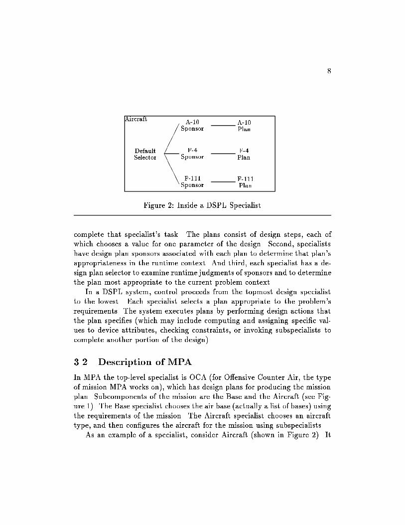
Each specialist contains design knowledge necessary to accomplish a por-tion of the design (see Figure 2). Each specialist has several types of knowl-edge but, for simplicity, we will describe only three. First, explicit designplans in each specialist encode sequences of possible actions to successfully
2MPA actually implements a very simpli�ed version of the problem.

7
OCA
��
��
��
���
QQQQQQQQQ
Base Aircraft
JJJJJJ
Conf.F-111
Conf.F-4
Conf.A-10
Figure 1: Organization of MPA, a DSPL Problem Solver
8
Aircraft
DefaultSelector
�����
AAAAA
A-10Sponsor
F-4Sponsor
F-111Sponsor
A-10Plan
F-4Plan
F-111Plan
Figure 2: Inside a DSPL Specialist
complete that specialist's task. The plans consist of design steps, each ofwhich chooses a value for one parameter of the design. Second, specialistshave design plan sponsors associated with each plan to determine that plan'sappropriateness in the runtime context. And third, each specialist has a de-sign plan selector to examine runtime judgments of sponsors and to determinethe plan most appropriate to the current problem context.
In a DSPL system, control proceeds from the topmost design specialistto the lowest. Each specialist selects a plan appropriate to the problem'srequirements. The system executes plans by performing design actions thatthe plan speci�es (which may include computing and assigning speci�c val-ues to device attributes, checking constraints, or invoking subspecialists tocomplete another portion of the design).
3.2 Description of MPA
In MPA the top-level specialist is OCA (for O�ensive Counter Air, the typeof mission MPA works on), which has design plans for producing the missionplan. Subcomponents of the mission are the Base and the Aircraft (see Fig-ure 1). The Base specialist chooses the air base (actually a list of bases) usingthe requirements of the mission. The Aircraft specialist chooses an aircrafttype, and then con�gures the aircraft for the mission using subspecialists.
As an example of a specialist, consider Aircraft (shown in Figure 2). It

9
(PLAN
(NAME A-10)
(SPONSOR A-10-Sponsor)
(PURPOSE ``considering the feasibility of an A-10 for the mission'')
(ACHIEVED ``chose an A-10 for the mission'')
(BODY
AssignAircraftType
ChooseSquadron
AssignBase
GetRange
(DESIGN Configure-A-10)))
Figure 3: MPA's A-10 Plan
contains a selector, in this case it is the default selector built into DSPL. Thedefault selector simply chooses the best plan, according to ratings assignedby the sponsors, and if there are no good plans it fails.3 Aircraft also containsthree sponsors, one for each of its plans. It has a plan for each aircraft type(A-10, F-4, and F-111).
The DSPL code for Aircraft's A-10 Plan is given in Figure 3. MPAdecides whether A-10 is the appropriate aircraft type for the mission usingits sponsor-selector mechanism described above. If A-10 is appropriate, thisplan is executed. The BODY contains a list of the steps in the plan. It �rstnotes the aircraft type, then chooses a squadron. The base is determinedfrom the chosen squadron and then the range to the target is computed.Finally, the aircraft is con�gured for the mission (bomb and fuel load) bycalling the subspecialist Con�gure-A-10.
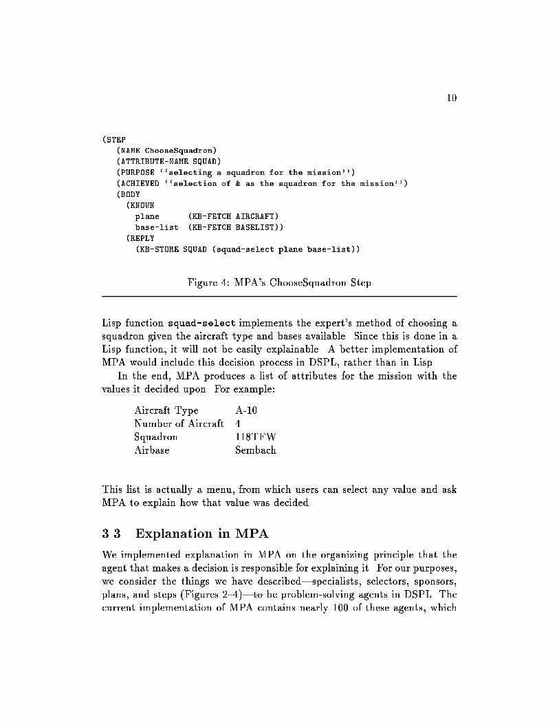
One of the steps, ChooseSquadron, is shown in Figure 4. Steps in DSPLset the value of a single design attribute, so the step �rst identi�es the at-tribute it sets (SQUAD). The DSPL functions KB-FETCH and KB-STORE fetchand store attribute values of the design. The KNOWN section of the body isa facility for de�ning local variables for known attributes. REPLY containsthe main work of the step. In this case the REPLY simply stores an attributevalue but, in general, it could do more work to decide on the value. The
3DSPL contains a mechanism, not described here, for dealing with failures. Brown andChandrasekaran [1] provide the details.
10
(STEP
(NAME ChooseSquadron)
(ATTRIBUTE-NAME SQUAD)
(PURPOSE ``selecting a squadron for the mission'')
(ACHIEVED ``selection of & as the squadron for the mission'')
(BODY
(KNOWN
plane (KB-FETCH AIRCRAFT)
base-list (KB-FETCH BASELIST))
(REPLY
(KB-STORE SQUAD (squad-select plane base-list))
Figure 4: MPA's ChooseSquadron Step
Lisp function squad-select implements the expert's method of choosing asquadron given the aircraft type and bases available. Since this is done in aLisp function, it will not be easily explainable. A better implementation ofMPA would include this decision process in DSPL, rather than in Lisp.
In the end, MPA produces a list of attributes for the mission with thevalues it decided upon. For example:
Aircraft Type A-10Number of Aircraft 4Squadron 118TFWAirbase Sembach...
...
This list is actually a menu, from which users can select any value and askMPA to explain how that value was decided.
3.3 Explanation in MPA
We implemented explanation in MPA on the organizing principle that theagent that makes a decision is responsible for explaining it. For our purposes,we consider the things we have described|specialists, selectors, sponsors,plans, and steps (Figures 2{4)|to be problem-solving agents in DSPL. Thecurrent implementation of MPA contains nearly 100 of these agents, which

11
The context of considering the feasibility of an A-10 for the mission determined that:
� plane was A-10
� base-list was Ramstein, Bitburg, Sembach
So 118TFW was an appropriate choice for Unit.
Figure 5: Explanation for a Step
call upon each other during the problem-solving process. All of these agentshave well-de�ned roles, so the system can explain an agent's decisions interms of the goals of its calling agent, the agent's own role in the pursuitof those goals, and the roles of other agents it called upon. To do this weadded slots called PURPOSE and ACHIEVED to the agent de�nitions in DSPLto hold text strings for describing the agents' goals. Then to explain howMPA decided on a particular attribute value, the explanation module putsthese strings together in an order that depends on the runtime context inwhich the decision was made. Given such an explanation users can selectany of the other agents and ask for further elaboration from them.
Suppose a user selected the value \118TFW" of the attribute \Unit". Theonly question users can ask MPA, the only explanation it can give, is a form of\How was it decided?" Thus, the user's selection in this case implicitly asks,\How was it decided that the Unit should be 118TFW?" The explanationis given in Figure 5. This decision was made by the ChooseSquadron stepso the explanation comes from that agent. The explanation �rst gives thepurpose of the calling agent (shown in italics), which comes from the A-10plan in this case. Then it gives the values of the local variables. Finally, itgives the value it chose for its attribute.
This explanation may be unsatisfying. A better explanation in this casemight be:
Assuming that we are to use A-10s and that the only bases avail-able are Ramstein, Bitburg, and Sembach, then 118TFW is theonly unit that ies A-10s out of these bases.
Some of the di�erence between this and Figure 5 is the quality of the En-glish text. The only content di�erence, and content has been our focus, is inconnecting the assumptions (values of local variables) to the �nal decision.MPA could do this better if the �nal decision were made using DSPL rather

12
The context of considering the feasibility of an A-10 for the mission determined that:
� plane was A-10
� base-list was Ramstein, Bitburg, Sembach
� units-with-A10 was 118TFW
So 118TFW was an appropriate choice for Unit.
Figure 6: Improved Explanation for a Step
than the Lisp function squad-select. A slightly improved version of theexplanation would appear as in Figure 6. Because the explanation module isessentially just translating DSPL code into text, the quality of the program-ming a�ects the quality of the explanation. This is a little bit undesirablebut also unavoidable in a system that has to explain itself using only its ownproblem-solving knowledge.
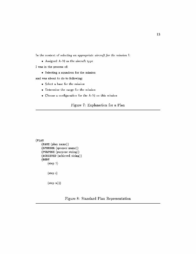
Users can select any of the local variables given in the explanation (i.e.,plane and base-list) for further elaboration. For example, to �nd out whyplane is A-10. This would result in getting an explanation from another step,since attribute values are determined by steps. Or users can select the callingagent for further explanation. This would result in an explanation from theA-10 plan, shown in Figure 7. As with the step explanation, the contextcomes from the calling agent, the Aircraft specialist here. The bulleted itemsare the purposes from the called agents. Additionally, the explanation showswhere the agent was in its procedure. In this explanation, since the userarrived here from the ChooseSquadron step, the plan had completed theAssignAircraftType step, was in the process of doing the ChooseSquadronstep, and had yet to do the AssignBase and GetRange steps and completethe con�guration.
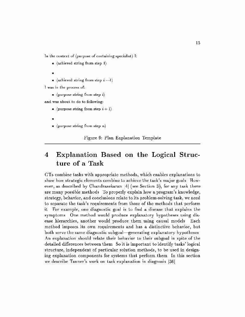
The explanations shown here are generated from explanation templates.Each agent type has a standard representation form from which we derivedits explanation template. A simpli�ed version of the standard form for plansis shown in Figure 8 (the simpli�cation is that in addition to steps, planscan contain DESIGN calls to subspecialists as in Figure 3). Figure 9 shows acorrespondingly simpli�ed explanation template for plans, assuming that itis entered from step i. Thus, a plan's explanations are put together out ofthe goals of its calling specialist and the goals of the steps it calls.
13
In the context of selecting an appropriate aircraft for the mission I:
� Assigned A-10 as the aircraft type.
I was in the process of:
� Selecting a squadron for the mission.
and was about to do to following:
� Select a base for the mission.
� Determine the range for the mission.
� Choose a con�guration for the A-10 on this mission.
Figure 7: Explanation for a Plan
(PLAN(NAME hplan namei)(SPONSOR hsponsor namei)(PURPOSE hpurpose stringi)(ACHIEVED hachieved stringi)(BODY
hstep 1i...hstep ii...hstep ni))
Figure 8: Standard Plan Representation
14
Putting explanations together out of \canned" text, the way MPA does, isnot a very sophisticated method of text generation. However, the importantpoint here is that the roles of the various agents|specialists, plans, steps,etc.|and their relationships de�ne the kinds of things that can be said andhow these things go together to make sensible explanations. These roles andrelationships are de�ned by the GT, in this case Design by Plan Selectionand Re�nement. We have more work to do on developing a taxonomy ofPURPOSEs for the various agents, and then showing how to use the taxonomyfor explaining. However, our aim for MPA was to demonstrate that GTprograms provide the structures needed to generate explanations of strategyand steps.
15
In the context of hpurpose of containing specialisti I:
� hachieved string from step 1i
�...
� hachieved string from step i � 1i
I was in the process of:
� hpurpose string from step ii
and was about to do to following:
� hpurpose string from step i + 1i
�...
� hpurpose string from step ni
Figure 9: Plan Explanation Template
4 Explanation Based on the Logical Struc-
ture of a Task
GTs combine tasks with appropriate methods, which enables explanations toshow how strategic elements combine to achieve the task's major goals. How-ever, as described by Chandrasekaran [4] (see Section 3), for any task thereare many possible methods. To properly explain how a program's knowledge,strategy, behavior, and conclusions relate to its problem-solving task, we needto separate the task's requirements from those of the methods that performit. For example, one diagnostic goal is to �nd a disease that explains thesymptoms. One method would produce explanatory hypotheses using dis-ease hierarchies, another would produce them using causal models. Eachmethod imposes its own requirements and has a distinctive behavior, butboth serve the same diagnostic subgoal|generating explanatory hypotheses.An explanation should relate their behavior to their subgoal in spite of thedetailed di�erences between them. So it is important to identify tasks' logicalstructure, independent of particular solution methods, to be used in design-ing explanation components for systems that perform them. In this sectionwe describe Tanner's work on task explanation in diagnosis [36].
16
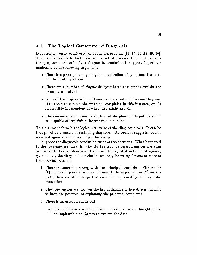
4.1 The Logical Structure of Diagnosis
Diagnosis is usually considered an abduction problem [12, 17, 20, 28, 29, 30].That is, the task is to �nd a disease, or set of diseases, that best explainsthe symptoms. Accordingly, a diagnostic conclusion is supported, perhapsimplicitly, by the following argument:
� There is a principal complaint, i.e., a collection of symptoms that setsthe diagnostic problem.
� There are a number of diagnostic hypotheses that might explain theprincipal complaint.
� Some of the diagnostic hypotheses can be ruled out because they are:(1) unable to explain the principal complaint in this instance, or (2)implausible independent of what they might explain.
� The diagnostic conclusion is the best of the plausible hypotheses thatare capable of explaining the principal complaint.
This argument form is the logical structure of the diagnostic task. It can bethought of as a means of justifying diagnoses. As such, it suggests speci�cways a diagnostic conclusion might be wrong.
Suppose the diagnostic conclusion turns out to be wrong. What happenedto the true answer? That is, why did the true, or correct, answer not turnout to be the best explanation? Based on the logical structure of diagnosis,given above, the diagnostic conclusion can only be wrong for one or more ofthe following reasons:
1. There is something wrong with the principal complaint. Either it is(1) not really present or does not need to be explained, or (2) incom-plete, there are other things that should be explained by the diagnosticconclusion.
2. The true answer was not on the list of diagnostic hypotheses thoughtto have the potential of explaining the principal complaint.
3. There is an error in ruling out.
(a) The true answer was ruled out. It was mistakenly thought (1) tobe implausible or (2) not to explain the data.
17
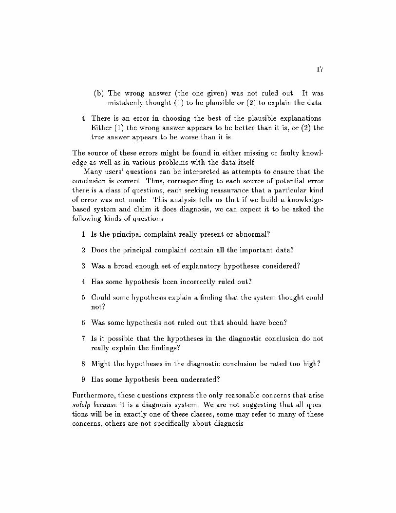
(b) The wrong answer (the one given) was not ruled out. It wasmistakenly thought (1) to be plausible or (2) to explain the data.
4. There is an error in choosing the best of the plausible explanations.Either (1) the wrong answer appears to be better than it is, or (2) thetrue answer appears to be worse than it is.
The source of these errors might be found in either missing or faulty knowl-edge as well as in various problems with the data itself.
Many users' questions can be interpreted as attempts to ensure that theconclusion is correct. Thus, corresponding to each source of potential errorthere is a class of questions, each seeking reassurance that a particular kindof error was not made. This analysis tells us that if we build a knowledge-based system and claim it does diagnosis, we can expect it to be asked thefollowing kinds of questions.
1. Is the principal complaint really present or abnormal?
2. Does the principal complaint contain all the important data?
3. Was a broad enough set of explanatory hypotheses considered?
4. Has some hypothesis been incorrectly ruled out?
5. Could some hypothesis explain a �nding that the system thought couldnot?
6. Was some hypothesis not ruled out that should have been?
7. Is it possible that the hypotheses in the diagnostic conclusion do notreally explain the �ndings?
8. Might the hypotheses in the diagnostic conclusion be rated too high?
9. Has some hypothesis been underrated?
Furthermore, these questions express the only reasonable concerns that arisesolely because it is a diagnosis system. We are not suggesting that all ques-tions will be in exactly one of these classes, some may refer to many of theseconcerns, others are not speci�cally about diagnosis.
18
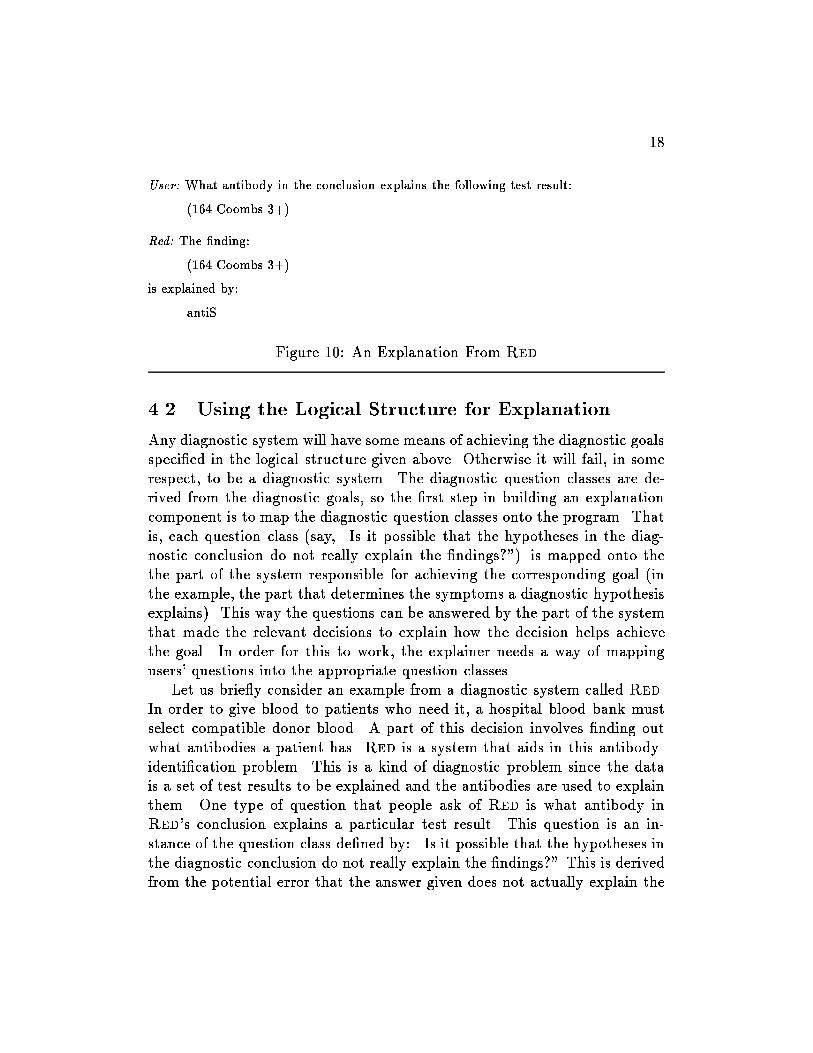
User: What antibody in the conclusion explains the following test result:
(164 Coombs 3+)
Red: The �nding:
(164 Coombs 3+)
is explained by:
antiS
Figure 10: An Explanation From Red
4.2 Using the Logical Structure for Explanation
Any diagnostic system will have some means of achieving the diagnostic goalsspeci�ed in the logical structure given above. Otherwise it will fail, in somerespect, to be a diagnostic system. The diagnostic question classes are de-rived from the diagnostic goals, so the �rst step in building an explanationcomponent is to map the diagnostic question classes onto the program. Thatis, each question class (say, \Is it possible that the hypotheses in the diag-nostic conclusion do not really explain the �ndings?") is mapped onto thethe part of the system responsible for achieving the corresponding goal (inthe example, the part that determines the symptoms a diagnostic hypothesisexplains). This way the questions can be answered by the part of the systemthat made the relevant decisions to explain how the decision helps achievethe goal. In order for this to work, the explainer needs a way of mappingusers' questions into the appropriate question classes.
Let us brie y consider an example from a diagnostic system called Red.In order to give blood to patients who need it, a hospital blood bank mustselect compatible donor blood. A part of this decision involves �nding outwhat antibodies a patient has. Red is a system that aids in this antibody-identi�cation problem. This is a kind of diagnostic problem since the datais a set of test results to be explained and the antibodies are used to explainthem. One type of question that people ask of Red is what antibody inRed's conclusion explains a particular test result. This question is an in-stance of the question class de�ned by: \Is it possible that the hypotheses inthe diagnostic conclusion do not really explain the �ndings?" This is derivedfrom the potential error that the answer given does not actually explain the
19
data. This, in turn, is derived from the diagnostic goal of explaining the data.So the question (\What explains a particular test result?") is directed to thecomponent of Red that chooses antibodies to explain particular elements ofdata. It produces an explanation such as the one in Figure 10. The \(164Coombs 3+)" is the notation for a test result and \antiS" is shorthand for\antibody to the S antigen". This process of mapping the question to thepart of the system that can answer it is not done automatically in Red. Thelogical structure of diagnosis was used in building Red's explanation compo-nent, but the mapping is hard-coded in the program. Tanner [36] describesexplanation for Red in more detail while Red itself was fully reported byJosephson, et al. [20]
The logical structure of diagnosis presented here is a common view of thediagnostic task [12, 17, 20, 28, 29, 30]. Not all approaches to diagnosis willshare this view. In fact, there is one common competing view|diagnosis asdescription, i.e., the goal of diagnosis is to describe the patient's state, notto �nd a cause for the symptoms. But if users and systems agree to a logicalstructure, it can be used to develop explanation for diagnosis in the mannerwe describe. The details will change if the model changes, but the method,and the idea, of using the logical structure to develop explanations remains.
5 Knowledge Justi�cation: Relating Problem
Solving to Causal Models
The integration and use of causal models in compiled problem-solving sys-tems has become increasingly prevalent. Xplain was probably the �rst sys-tem to provide explanations of problem-solving knowledge by showing how itwas obtained by compilation from other knowledge about the domain [26, 35].Our work on functional representations (FR) [31] is similar in showing how tocompile diagnostic programs from functional representations of mechanicaldevices. Following on this, Keuneke's work [22] showed how to use FR forjustifying diagnostic conclusions, which we describe in this section.
5.1 Background
Methods that carry out problem-solving tasks need knowledge of certainkinds and in particular forms. For example, establish-re�ne, a method for

20
hierarchical classi�cation, requires knowledge relating descriptions of situa-tions to descriptions of classes (see Section 2). If knowledge is not availablein this form, it must be derived from some other knowledge. We refer to thisderivation process as compilation [31, 35, 15], and to knowledge in the de-sired form as compiled knowledge [7]. The \other knowledge" has sometimesbeen called deep knowledge, but it is not necessarily deeper or better, onlyless compiled relative to the method that needs it. The compiled knowledgecan be justi�ed by referring to the knowledge from which it was compiled.
As with any compiled knowledge, compiled diagnostic knowledge can bejusti�ed by referring to the compilation process. Diagnosis also admits aninteresting variation on this type of justi�cation. If a system for diagnosingfaults in a mechanical device is compiled from a causal model of the device,then its diagnostic conclusions can be related to observations using the causalmodel. This justi�es the conclusion and validates the compiled knowledgethat produced it. The causal model could be used to perform diagnosis, andsystems have been built that do this [11, 27, 38], but for complex devices thelarge amount of causal information makes the diagnostic task very di�cult.In most diagnostic systems, the causal knowledge is compiled for greaterexpertise and optimum diagnostic performance. Then, if a causal story canbe put together, using the hypothesized diagnostic answer as a focus, weget the advantages of both worlds: the computational bene�ts of compiledknowledge to obtain the diagnostic answer, as well as the causal model tovalidate it.
In a diagnostic context, given the symptoms and the diagnostic conclu-sion, Keuneke showed how to use a causal model to justify the diagnosis atvarious levels of detail. In many situations a similar method will work tojustify individual rules in the knowledge base. Wick [39] developed a relatedidea: justifying a conclusion in terms of the standard arguments used bydomain experts. Both Wick and our work using FR produce justi�cationsby reference to knowledge not used, perhaps not even needed, to produce thesolution. However, one important di�erence is that justi�cations come fromknowledge that, in principle, could be used to compile diagnostic problemsolvers while Wick is not committed to any particular relationship betweenjusti�cation knowledge and problem-solving knowledge. The intent of Ke-uneke's [22] research was to continue e�orts in the development of a device-and domain-independent representation capable of modeling the core aspectsof device understanding; the extended goal is a cognitive model of device un-

21
derstanding. Although this work was driven by the task of explanation, therepresentation was designed to provide the basic primitives and organizationfor a variety of problem-solving tasks.
5.1.1 The Functional Representation
Initial e�orts to generate causal justi�cations [5, 6, 18, 25] focused on en-hancing Sembugamoorthy and Chandrasekaran's FR [31] to provide a repre-sentation with the necessary organization and primitives4.
Functional Representation is a representational scheme for the functionsand expected behavior of a device. FR represents knowledge about devicesin terms of the functions that the entire device is supposed to achieve andalso of the sequence of causal interactions among components that lead toachievement of the functions. FR takes a top-down approach to representinga device, in contrast to the bottom-up approach of behavior-oriented knowl-edge representation and reasoning schemes [10, 14]. In FR, the function ofthe overall device is described �rst and the behavior of each component (itscausal process) is described in terms of how it contributes to the function5.Figures 11 and 12 illustrate the top-level representation of a chemical pro-cessing plant.
In this representation, a device's function is its intended purpose. Func-tions describe a device's goals at the device level. For example, the functionof a chemical processing plant is to produce a certain product. It has com-ponents for supplying the reactants, stirring the substance, extracting theproduct, and so forth. But generating the product is a function of the deviceas a whole.
Functions are achieved by behaviors or causal processes. In the chem-ical processing plant example, the substance is produced by the causal se-quence of (1) input of the reactants into the reaction vessel, (2) allowingreactant contact, and then (3) extracting the product from the reaction ves-sel. In short, the functions are what is expected; the behaviors are how thisexpected result is attained. In FR, behaviors are represented as causal se-quences of transitions between partial states or predicates (e.g., (presentreactants rxvessel)).
4For a more current formal treatment of the representation, see [19]5A function's causal process is represented in the machine by its causal process descrip-
tion { CPD.

22
ChemProcPlant
LiquidFeedSystem
PressureControlSystem
TransferSystem
CoolingSystem
CondensateWithdrawalSystem
MixingSystem
AirFeedSystem
ControlLiquidFlow
ControlLiquidTemp
Condenser CoolantSystem
ControlAirPressure
ControlAirTemp
Sensor
produce.acid
reactantsupplied
PressureCtrl
extraction
SolidConcCtrl
airsupply
bubblemix
bubblesuspension
cool
cool2
LiquidConcCtrl
retrieveliquid
mix
suspension
condense providecoolant
heattransfer
controlamount
controlheat
controlpressure
controltemp
produce.signal
ControlAirFlow
controlflow
Figure 11: Functional Component Hierarchy
The device is represented at various levels. The topmost level describesthe functioning of the device by identifying which components and moredetailed causal processes are responsible for bringing about the various statetransitions. If a transition is achieved using a function of a component, thenext level describes the functioning of this component in terms of the rolesof its subcomponents, and so on. Ultimately, either by tracing through moredetailed causal processes or by expanding the causal processes of functionalcomponents, all the functions of a device can be related to its structure andthe function of the components within this structure.
5.1.2 Enhancing the Functional Representation
Early explanation work [5] simply used the FR as a tool to answer questionssuch as: (1) Why is this device needed? (2) What subcomponents does thisdevice require? (3) What does this function accomplish? (4) Why or whereis this function used in the device? (5) How is this function achieved?
Later, enhancements to the FR allowed the representation of state and
23
(amount acid below.threshold)
(present reactants rxvessel)
(occurred reaction rxvessel)
(amount heat rxvessel increased)
(condition rxvessel sufficient) (present product external.container)
By SupplyReactants
By ReactantContact
AsPer exothermic.reaction.se
By: CompensateOxidation.se
AsPer: products.replace.reactants
UsingFunction extraction
of TransferSystem
(present acid rxvessel)
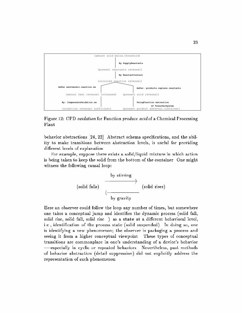
Figure 12: CPD oxidation for Function produce.acid of a Chemical ProcessingPlant
behavior abstractions [24, 22]. Abstract schema speci�cations, and the abil-ity to make transitions between abstraction levels, is useful for providingdi�erent levels of explanation.
For example, suppose there exists a solid/liquid mixture in which actionis being taken to keep the solid from the bottom of the container. One mightwitness the following causal loop:
by stirring||||||{i
(solid falls) (solid rises)h||||||{
by gravity
Here an observer could follow the loop any number of times, but somewhereone takes a conceptual jump and identi�es the dynamic process (solid fall,solid rise, solid fall, solid rise...) as a state at a di�erent behavioral level,i.e., identi�cation of the process state (solid suspended). In doing so, oneis identifying a new phenomenon; the observer is packaging a process andseeing it from a higher conceptual viewpoint. These types of conceptualtransitions are commonplace in one's understanding of a device's behavior| especially in cyclic or repeated behaviors. Nevertheless, past methodsof behavior abstraction (detail suppression) did not explicitly address therepresentation of such phenomenon.
24
For researchers interested in building models of devices solely to predictbehavior at a given level of detail, these abstractions will not be helpful.Instead, these abstractions provide the ability to tell a higher level story.Prediction is not driven solely by constraints of structure and low-level pro-cesses, but can be enriched and focused by knowledge of abstract processesand the inferences they dictate.
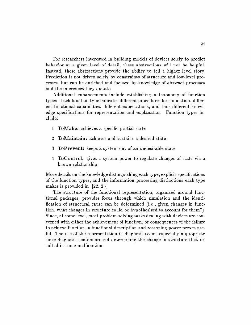
Additional enhancements include establishing a taxonomy of functiontypes. Each function type indicates di�erent procedures for simulation, di�er-ent functional capabilities, di�erent expectations, and thus di�erent knowl-edge speci�cations for representation and explanation. Function types in-clude:
1. ToMake: achieves a speci�c partial state
2. ToMaintain: achieves and sustains a desired state
3. ToPrevent: keeps a system out of an undesirable state
4. ToControl: gives a system power to regulate changes of state via aknown relationship.
More details on the knowledge distinguishing each type, explicit speci�cationsof the function types, and the information processing distinctions each typemakes is provided in [22, 23].
The structure of the functional representation, organized around func-tional packages, provides focus through which simulation and the identi-�cation of structural cause can be determined (i.e., given changes in func-tion, what changes in structure could be hypothesized to account for them?).Since, at some level, most problem-solving tasks dealing with devices are con-cerned with either the achievement of function, or consequences of the failureto achieve function, a functional description and reasoning power proves use-ful. The use of the representation in diagnosis seems especially appropriatesince diagnosis centers around determining the change in structure that re-sulted in some malfunction.

25
6 Causal Explanation: The Problem State-
ment
To illustrate the use of the representation, we pose the following problem:Given a set of observations and a diagnostic hypothesis, attempt to constructan explanation in the form of a causal story which starts with a diagnostichypothesis and ends with one or more of the observations to be explained.In the following, we examine how a functional representation can be used forthis purpose. Technical de�nitions of a few terms may be useful:
Observations: observable states, including a subset which are malfunctionsof the device subsystems or components. The following distinctionsabout observations are useful:
� Symptoms: abnormal states which are indicative of malfunctionsand trigger the diagnostic process, e.g., speci�cation of a drop fromnormal pressure.
� Malfunctions: observations which are malfunctions, e.g., spec-i�cation of a faulty pressure regulator. Malfunction observationsare generally also symptoms.
� Observable states which provide information about the device butdo not directly correspond to abnormalities, e.g., speci�cation oftemperature or pressure readings. Typically in a complex system,a large number of observations are used in the diagnostic processwhich provide focus for the problem-solving but do not necessarilyindicate problems (e.g., sensor readings).
Diagnostic Hypotheses: the set of malfunctioning components or missing(but expected) relationships between components. Each in the lattershould sooner or later, manifest itself as the malfunction of a subsystemwithin which the components lie.
Causal Explanation: Normally one expects a diagnosis to causally \ex-plain" the symptoms, even though in general the diagnosis actuallyshould explain all the observations. The explanation provided heretakes any given set of observations to be explained and tries to proposea causal path from the diagnostic hypothesis to these observations.
26
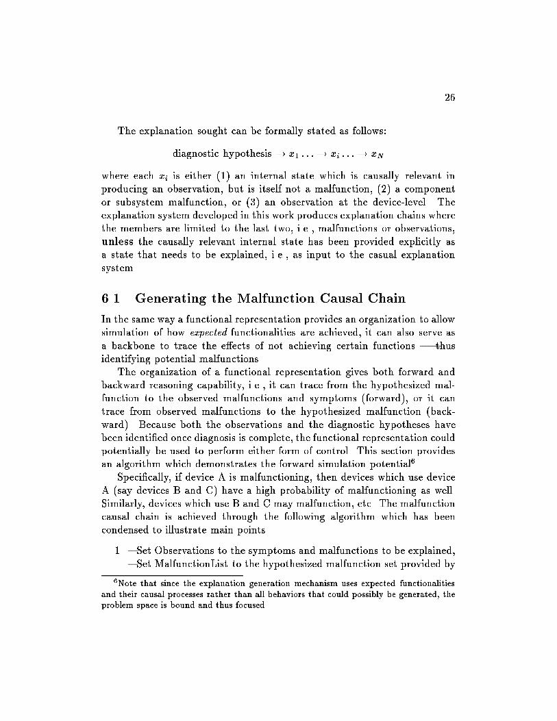
The explanation sought can be formally stated as follows:
diagnostic hypothesis ! x1 : : : ! xi : : : ! xN
where each xi is either (1) an internal state which is causally relevant inproducing an observation, but is itself not a malfunction, (2) a componentor subsystem malfunction, or (3) an observation at the device-level. Theexplanation system developed in this work produces explanation chains wherethe members are limited to the last two, i.e., malfunctions or observations,unless the causally relevant internal state has been provided explicitly asa state that needs to be explained, i.e., as input to the casual explanationsystem.
6.1 Generating the Malfunction Causal Chain
In the same way a functional representation provides an organization to allowsimulation of how expected functionalities are achieved, it can also serve asa backbone to trace the e�ects of not achieving certain functions | thusidentifying potential malfunctions.
The organization of a functional representation gives both forward andbackward reasoning capability, i.e., it can trace from the hypothesized mal-function to the observed malfunctions and symptoms (forward), or it cantrace from observed malfunctions to the hypothesized malfunction (back-ward). Because both the observations and the diagnostic hypotheses havebeen identi�ed once diagnosis is complete, the functional representation couldpotentially be used to perform either form of control. This section providesan algorithm which demonstrates the forward simulation potential6.
Speci�cally, if device A is malfunctioning, then devices which use deviceA (say devices B and C) have a high probability of malfunctioning as well.Similarly, devices which use B and C may malfunction, etc. The malfunctioncausal chain is achieved through the following algorithm which has beencondensed to illustrate main points.
1. { Set Observations to the symptoms and malfunctions to be explained,{ Set MalfunctionList to the hypothesized malfunction set provided by
6Note that since the explanation generation mechanism uses expected functionalitiesand their causal processes rather than all behaviors that could possibly be generated, theproblem space is bound and thus focused.

27
the diagnosis,{ Initialize MalfunctionObject to an individual malfunction in this set(diagnosed hypotheses and their relationship to observations are con-sidered individually)
2. Find all functions which made use of the function which is malfunc-tioning (MalfunctionObject), call this set PossibleMalfunctions,
3. For each element in PossibleMalfunctions (call the speci�c functionPossMal) consider the signi�cance of the e�ect of MalfunctionObjecton the function.
� if no e�ect on PossMal then remove from PossibleMalfunctions |MalfunctionObject is not causing future problems. Consider thenext element in PossibleMalfunctions.
� else maintain (Malfunction ! Malfunction) explanation chain;MalfunctionObject is now known to cause a malfunction to Poss-Mal. Speci�cally MalfunctionObject ! PossMal is appended tochain. Note that this step will ultimately place any potential mal-functions in a malfunction chain, including those which are in theset of Observations. Continue.
4. Check the states in the causal process description of the a�ected Pos-sibleMalfunction. Would noncompletion of these states explain anysymptom(s) in Observations?
� if yes, append to ExplainedSymptoms and print the chain whichled to this symptom. Complete the malfunction explanation chainby continuing.
5. Set MalfunctionObject to PossMal. (MalfunctionObject (= PossMal)
6. Repeat process from step 2 until all symptoms are in ExplainedSymp-toms or the top level causal process description of the device has beenreached.
7. The Process from step 1 is repeated until all elements of Malfunction-List have been considered.

28
Step 2 is easily accomplished through the component hierarchy of thefunctional representation (example in Section 6.2). Step 3 and 4 are moreintricate and involve knowledge of function type and the achievement of theintended causal processes.
For example, in step 3, to determine the e�ects of a malfunction on otherfunctions, one must consider the possible consequences of malfunctioningcomponents. In general, the malfunction of a component in a device cancause one or more of the following three consequences:
NOT Function: expected results of the function will not be present. Giventhat the malfunction is not producing the expected results within thecausal process, what states in those causal processes will not occur,and will lack of this functionality cause the malfunctions of functionsin which the malfunctioning component was used?
Parameter Out-of-Range: expected results of the function are a�ected,but behavior is still accomplished to a limited degree. Sometimes com-ponents may be considered malfunctioning yet can still perform thebehavior (or value of some substance parameter) to the extent neededfor future use.
New Behaviors: the malfunction results in behaviors and states which werenot those intended for normal functioning.
The determination of whether a proposed malfunction can explain asymptom, step 4 in the explanation algorithm, can be established by a num-ber of means:
1. Check each state in the causal process description where the malfunc-tioning component is used to see if there is a direct match between asymptom and not achieving an expected state.
2. Check to see if the function which is malfunctioning has an explicitmalfunction causal process description and if the symptom is includedtherein. 7
7See [22] for knowledge of function type and detail on functions with explicit malfunc-tion causal processes.
29
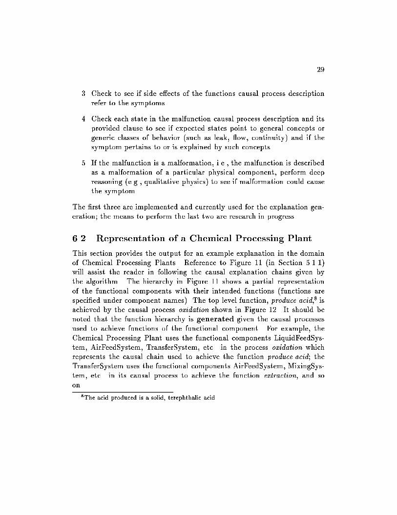
3. Check to see if side e�ects of the functions causal process descriptionrefer to the symptoms.
4. Check each state in the malfunction causal process description and itsprovided clause to see if expected states point to general concepts orgeneric classes of behavior (such as leak, ow, continuity) and if thesymptom pertains to or is explained by such concepts.
5. If the malfunction is a malformation, i.e., the malfunction is describedas a malformation of a particular physical component, perform deepreasoning (e.g., qualitative physics) to see if malformation could causethe symptom.
The �rst three are implemented and currently used for the explanation gen-eration; the means to perform the last two are research in progress.
6.2 Representation of a Chemical Processing Plant
This section provides the output for an example explanation in the domainof Chemical Processing Plants. Reference to Figure 11 (in Section 5.1.1)will assist the reader in following the causal explanation chains given bythe algorithm. The hierarchy in Figure 11 shows a partial representationof the functional components with their intended functions (functions arespeci�ed under component names). The top level function, produce.acid,8 isachieved by the causal process oxidation shown in Figure 12. It should benoted that the function hierarchy is generated given the causal processesused to achieve functions of the functional component. For example, theChemical Processing Plant uses the functional components LiquidFeedSys-tem, AirFeedSystem, TransferSystem, etc. in the process oxidation whichrepresents the causal chain used to achieve the function produce.acid; theTransferSystem uses the functional components AirFeedSystem, MixingSys-tem, etc. in its causal process to achieve the function extraction, and soon.
8The acid produced is a solid, terephthalic acid.

30
6.2.1 The Problem
The Coolant System (identi�ed at the right of Figure 11 ) is used to providecoolant water to a Condenser so that it can be used to transfer heat from thevapor in the Condenser (see Figure 13). Suppose the coolant water has beencompletely cut o�. A diagnostic system has concluded that a malfunction ofthe function provide.coolant of the Coolant System explains the symptoms ofNOT (present product external.container) and NOT (temperature rxvesselat.threshold). Speci�cally, MalfunctionObject is fprovide.coolant of CoolantSystemg and the Observations to be explained are fNOT (present productexternal.container), NOT (temperature rxvessel at.threshold) g. The systemproduces the following three casual stories.
6.2.2 Causal Story 1: Generation of Causal Connections
The causal process SupplyReactants uses the functions retrieveliquid andLiquidConcCtrl, in addition to the LiquidFeedSystem and AirFeedSystem.The explanation system generates the following:
The symptom
NOT (present product external.container)
is explained by the following chain:
NOT provide.coolant causes
malfunction in condense causing
malfunction in retrieveliquid causing
malfunction in LiquidConcCtrl causing
problems in behavior SupplyReactants
which is used in behavior oxidation and
indicates malfunction of the top level
function and results in
NOT (present product external.container)
---
The following symptoms are not explained:
NOT (temperature rxvessel at.threshold)
The idea here is that if the required amount of reactants is not available,the product is not produced as desired and thus can not be retrieved. Theexplanation system generates this chain by using the following information:
31
(present vapor condenser)
(surrounded vapor coolant)
(temperature vapor decreased)
(condensed vapor condenser)
(present liquid condenser)
UsingFunction:provide.coolant
of CoolantSystem
UsingFunction:heat.transfer
of CoolantSystem
AsPer:heat.transfer/condensation
at dewpoint
AsPer: Identity
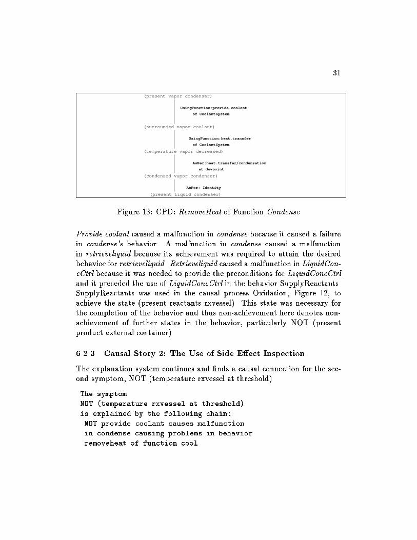
Figure 13: CPD: RemoveHeat of Function Condense
Provide.coolant caused a malfunction in condense because it caused a failurein condense's behavior. A malfunction in condense caused a malfunctionin retrieveliquid because its achievement was required to attain the desiredbehavior for retrieveliquid. Retrieveliquid caused a malfunction in LiquidCon-cCtrl because it was needed to provide the preconditions for LiquidConcCtrland it preceded the use of LiquidConcCtrl in the behavior SupplyReactants.SupplyReactants was used in the causal process Oxidation, Figure 12, toachieve the state (present reactants rxvessel). This state was necessary forthe completion of the behavior and thus non-achievement here denotes non-achievement of further states in the behavior, particularly NOT (presentproduct external.container).
6.2.3 Causal Story 2: The Use of Side E�ect Inspection
The explanation system continues and �nds a causal connection for the sec-ond symptom, NOT (temperature rxvessel at.threshold).
The symptom
NOT (temperature rxvessel at.threshold)
is explained by the following chain:
NOT provide.coolant causes malfunction
in condense causing problems in behavior
removeheat of function cool

32
Since cool is not a top level function of the chemical processing plant, thetrace continues until all consequences are determined.
The symptom
NOT (temperature rxvessel at.threshold)
is explained by the following chain:
NOT provide.coolant causes
malfunction in condense causing
malfunction in cool causing problems
in behavior compensate.oxidation.se
a notable side effect behavior used in
oxidation and indicates
NOT (temperature rxvessel at.threshold)
---
The following symptoms are not explained
(present product external.container)
Notice that this explanation identi�es that the symptom was observed in aside e�ect behavior (compensation for e�ects of the reaction) rather thana behavior of the main functionality (production of acid).
The statement of which symptoms are not explained indicates those thatwere not explained in the speci�c causal chain. A �nal statement is madewhen the system has inspected all pertinent causal chains (as seen in thenext causal story).
6.2.4 Causal Story 3: Using Subfunction Connections for CausalFocus
The �nal causal path is achieved via causal connections obtained speci�callythrough the knowledge of subfunctions. In its speci�cation, the functionextraction has a provided clause which speci�es that the solid acid slurrymust have the proper consistency so that ow through the extraction tubeis possible. The function SolidConcCtrl is present in this device for the solepurpose of producing these conditions for extraction.
The purpose of SolidConcCtrl is to keep the solid suspended and theconcentration in the reaction vessel at the proper consistency. In the Con-densateWithdrawalSystem, the retrieveliquid function uses the Condenser to

33
retrieve the condensate from the vapor produced. TheMixtureLevelCtrl func-tion then uses a feedback controller to maintain the ow and thus the desiredamount of liquid in the reaction vessel | which ensures that the acid slurryhas the proper consistency. If the liquid is not retrievable, then obviouslythe condensate ow cannot be controlled and consistency of the acid in thevessel is not maintained. The explanation system provides this explanatorystory as follows:
One function affected by provide.coolant
is SolidConcCtrl which is a necessary
subfunction of extraction
The symptom
NOT (present product external.container)
is explained by the following chain:
NOT provide.coolant causes
malfunction in condense causing
malfunction in retrieveliquid causing
malfunction in MixtureLevelCtrl causing
malfunction in SolidConcCtrl causing
malfunction in extraction causing
malfunction in produce.acid causing
NOT (present product external.container)
---
All symptoms have been explained.
6.3 Discussion
The intrinsic limitations of a functional representation for explanation arisefrom its intrinsic limitations for simulation. The representation uses prepack-aged causal process descriptions which are organized around the expectedfunctions of a device. Simulations of malfunctioning devices are thus limitedto statements of what expectations are \not" occurring.
This limitation e�ects the capabilities for explanation in two signi�cantways. First, the functional representation is not capable of generating causalstories of malfunctions which interact unless the device representation hasthis interaction explicitly represented. Similar problems regarding the inter-

34
actions of malfunctions arise in diagnosis [33]. Secondly, \new" behaviors,i.e., behaviors which are not those intended for normal functioning but whicharise due to a change in device structure, could potentially lead to symptomswhich cannot be explained using the functional representation. Current re-search e�orts focus on how a functional organization might be used to de-termine these new behavioral sequences, in addition to how conventionalmethods of qualitative reasoning may be integrated.
7 Additional Applications of a Functional Model
The idea of considering how devices work is a generally useful concept whichprovides a focus for reasoning about objects. Since goals can be attributed tomany types of objects, a general representational language, focused aroundfunctionality, can potentially model an understanding of a variety of objecttypes, i.e., truly a \device-independent" representation. In addition, theorganization around functions helps to focus a reasoner's attention towardexpected goals; something works like it does because it is meant to achieve aspeci�c purpose. The practical uses of having a functionally oriented under-standing of how something works can be seen in the following applications:
diagnosis: How something works provides information about what functionsto expect from working models, and thus implicitly knowledge of mal-functioning models. This helps to enumerate malfunction modes andto derive what observable consequences follow for a given malfunction.
learning: In diagnosis, if a hypothesis has been made and a causal chaincannot be found that connects the hypothesis to the symptoms, a learn-ing process could be triggered. Speci�cally, a diagnosis which cannotbe causally connected to the symptoms might cause suspicion, not onlyabout the diagnostic result, but also about the knowledge used in thediagnostic process. Use of the malfunction causal explanation capabil-ities can help explicate erroneous malfunction hypotheses and aid inpointing to alternatives. [37]
repair/replacement: Knowledge of how a device works indicates knowl-edge of its teleology. Replacement with objects of like teleology can beconsidered.
35
design/redesign: Knowledge of what functionalities are desired can pointthe designer to necessary components. [16, 19]
planning: The representation of plans (as devices) provides an understand-ing of how the plan's goals are achieved. [5]
determination of optimum use: Knowledge of how a device works canprovide information regarding how to use the device to its maximumpotential.
analogy: Organizing knowledge of how one object works provides links fordetermining how a similar object might operate.
prediction: Knowledge of expected functionalities focuses reasoning for de-termining what will happen in a device. [32]
simulation: Simulation of expected device behavior is useful for problemsolving, in particular, design. [34, 19]
explanation: Having the knowledge of how something works allows one tosimulate and explain the mechanism, i.e., tutorial purposes.
8 Conclusion
In this paper we have surveyed the work done at the Ohio State Laboratoryfor AI Research on knowledge systems explanation. We consider the expla-nation problem to have three aspects: the explanation content, the form ofpresentation, and the manner of presentation. We have concentrated on theexplanation content, which we see as having four parts: explaining problem-solving steps, strategy, and task, and justifying knowledge. Most of ourwork on these has been guided by GT theory|any task can be accomplishedby many di�erent methods, the combination of a particularly appropriate,domain-independent, method with a task is called a generic task. GT re-search has identi�ed several generic tasks and a knowledge system that usesa generic task can explain its steps and its strategy, since strategy is anaspect of the method. By combining generic tasks with a theory of tasks,independent of method, it is possible to give explanations that show how asystem's method achieves the task goals. Using the functional representation,
36
also developed at the LAIR, to represent general purpose knowledge in theknowledge system's domain we can justify its problem-solving knowledge byshowing how it was derived. Individually, each of the e�orts described heresolves a few problems and leaves many issues unaddressed. Taken as a whole,they represent an attempt to explore the wide range of roles that knowledgeplays in explanation|knowledge about tasks, methods and strategies, systemdesign, background domain knowledge, and memory for particular problem-solving instances|and the bene�ts of explicitly representing these kinds ofknowledge.
Acknowledgments
This work has been supported by the Air Force O�ce of Scienti�c Research(grant 89-0250), the Defense Advanced Research Projects Agency (contractsF30602-85-C-0010 and F49620-89-C-0110), and the National Heart Lung andBlood Institute (grant HL-38776). In addition we would like to thank JohnJosephson who led the MPA project and provided insightful comment onthe rest of the work reported here; the other members of the MPA team:Dean Allemang, Matt DeJongh, Ron Hartung, and Dave Herman; and ourfriends and colleagues at the LAIR who have contributed to the ideas pre-sented here through their work, discussions, and friendship. We also thankBill Swartout and Cecile Paris for their helpful comments on an earlier draft.These individuals do not necessarily endorse the entire contents of this pa-per, however. The authors accept full responsibility for that, including anyinadvertent errors.
References
[1] D. C. Brown and B. Chandrasekaran. Design Problem Solving: Knowl-
edge Structures and Control Strategies. Morgan Kaufmann, Inc., SanMateo, CA, 1989.
[2] T. Bylander and S. Mittal. CSRL: A language for classi�catory problemsolving and uncertainty handling. AI Magazine, 7(3):66{77, August1986.
37
[3] B. Chandrasekaran. Generic tasks in knowledge-based reasoning: High-level building blocks for expert system design. IEEE Expert, 1(3):23{30,Fall 1986.
[4] B. Chandrasekaran. Design problem solving: A task analysis. AI Mag-
azine, 11(4):59{71, Winter 1990.
[5] B. Chandrasekaran, J. Josephson, and A. Keuneke. Functional repre-sentation as a basis for explanation generation. In Proceedings of IEEE
International Conference on Systems, Man, and Cybernetics, pages 726{731, October 1986.
[6] B. Chandrasekaran, J. R. Josephson, A. M. Keuneke, and D. Herman.Building routine planning systems and explaining their behavior. Inter-national Journal of Man-Machine Studies, 30:377{398, 1989.
[7] B. Chandrasekaran and S. Mittal. On deep versus compiled approachesto diagnostic problem solving. International Journal of Man Machine
Studies, 19:425{436, 1983.
[8] B. Chandrasekaran, M. C. Tanner, and J. R. Josephson. Explainingcontrol strategies in problem solving. IEEE Expert, 4(1):9{24, Spring1989.
[9] W. J. Clancey. Heuristic classi�cation. Arti�cial Intelligence, 27(3):289{350, December 1985.
[10] J. Crawford, A. Farquhar, and B. Kuipers. QPC: A compiler fromphysical models into qualitative di�erential equations. In Proceedings
of the 8th National Conference on Arti�cial Intelligence, pages 365{372,1990.
[11] R. Davis, H. Shrobe, W. Hamscher, K. Wieckert, M. Shirley, andS. Polit. Diagnosis based on description of structure and function. InAAAI-82, pages 137{142, Pittsburgh, PA, August 18{20 1982.
[12] J. deKleer and B. C. Williams. Diagnosing multiple faults. Arti�cial
Intelligence, 32(1):97{130, April 1987.
38
[13] C. Engelman, J. K. Millen, and E. A. Scarl. Knobs: An integrated AIinteractive planning architecture. Technical Report DSR-83-162, TheMITRE Corporation, Bedford, MA, 1983.
[14] B. Falkenhainer and K. Forbus. Setting up large-scale qualitative mod-els. In Proceedings of the 7th National Conference on Arti�cial Intelli-
gence, pages 301{306, 1988.
[15] A. Goel. Knowledge compilation: A symposium. IEEE Expert, Spe-
cial Track on Functional Representation and Modeling, 6(2):71{73, April1991.
[16] A. Goel and B. Chandrasekaran. Functional representation of designsand redesign problem solving. In Proceedings of IJCAI-11. IJCAI, Au-gust 1989.
[17] A. M. Harvey and J. Bordley III. Di�erential Diagnosis, the Interpre-
tation of Clinical Evidence. W. B. Saunders, Philadelphia, 1972.
[18] D. Herman, A. Keuneke, M. C. Tanner, R. Hartung, and J. Josephson.MPA: A mission planning assistant in the Knobs domain. In Expert
Systems: Proceedings of a Workshop, pages 103{116, Paci�c Grove, CA,April 16{18 1986.
[19] Y. Iwasaki and B. Chandrasekaran. Design veri�cation throughfunction- and behavior-oriented representations: Bridging the gap be-tween function and behavior. In Proceedings of the Conference on Arti-
�cial Intelligence in Design, 1992.
[20] J. R. Josephson, B. Chandrasekaran, J. W. Smith, Jr., and M. C. Tan-ner. A mechanism for forming composite explanatory hypotheses. IEEETransactions on Systems, Man, and Cybernetics, SMC-17(3):445{454,May/June 1987.
[21] J. R. Josephson, D. Smetters, R. Fox, D. Oblinger, A. Welch, andG. Northrup. Integrated Generic Task Toolset: Fafner release 1.0, in-troduction and user's guide. Technical Report 89-JJ-FAFNER, Lab. forAI Research, Ohio State Univ., Columbus, OH, June 1 1989.
39
[22] A. Keuneke. Machine Understanding of Devices: Causal Explanation of
Diagnostic Conclusions. PhD thesis, The Ohio State University, Colum-bus, Ohio, 1989.
[23] A. Keuneke. Device representation: The signi�cance of functional knowl-edge. IEEE Expert, Special Track on Functional Representation and
Modeling, 6(2):22{25, April 1991.
[24] A. Keuneke and D. Allemang. Understanding devices: Representingdynamic states. Technical report, The Ohio State University, 1988.
[25] A. Keuneke and D. Allemang. Exploring the \No-Function-In-Structure" Principle. Journal of Experimental and Theoretical Arti�cial
Intelligence, 1:79{89, 1989.
[26] R. Neches, W. R. Swartout, and J. D. Moore. Enhanced maintenanceand explanation of expert systems through explicit models of their devel-opment. IEEE Transactions on Software Engineering, SE-11(11):1337{1351, November 1985.
[27] R. S. Patil. Causal Representation of Patient Illness for Electrolyte
and Acid-Base Diagnosis. PhD thesis, MIT Lab for Computer Science,Cambridge, Massachusetts, 1981. TR-267.
[28] H. E. Pople. The formation of composite hypotheses in diagnosic prob-lem solving. In Proceedings of the 5th IJCAI, pages 1030{1037, Cam-bridge, MA, August 22{25, 1977.
[29] J. Reggia. Diagnostic expert systems based on a set covering model. In-ternational Journal of Man-Machine Studies, 19(5):437{460, November1983.
[30] R. Reiter. A theory of diagnosis from �rst principles. Arti�cial Intelli-gence, 32(1):57{95, April 1987.
[31] V. Sembugamoorthy and B. Chandrasekaran. Functional representa-tion of devices and compilation of diagnostic problem solving systems.In J. L. Kolodner and C. K. Riesbeck, editors, Experience, Memory,
and Reasoning, pages 47{73. Lawrence Erlbaum Assoc., Hillsdale, NewJersey, 1986.

40
[32] J. Sticklen. MDX2, An Integrated Medical Diagnostic System. PhDthesis, The Ohio State University, 1987.
[33] J. Sticklen, B. Chandrasekaran, and J. Josephson. Control issues in clas-si�catory diagnosis. In Proceedings of IJCAI-9, pages 300{306. IJCAI,August 1985.
[34] J. Sun and J. Sticklen. Steps toward tractable envisionment via a func-tional approach. In Second AAAI Workshop on Model Based Reasoning,pages 50{56. AAAI, 1990.
[35] W. R. Swartout. Xplain: A system for creating and explaining expertconsulting programs. Arti�cial Intelligence, 21(3):285{325, September1983.
[36] M. C. Tanner. Explaining Knowledge Systems: Justifying Diagnostic
Conclusions. PhD thesis, Dept. of Computer and Information Science,Ohio State University, Columbus, OH, March 1989.
[37] M. Weintraub. An Explanation Approach to Assigning Credit. PhDthesis, The Ohio State University, Columbus, Ohio, 1991.
[38] S. M. Weiss, C. A. Kulikowski, S. Amarel, and A. Sa�r. A model-based method for computer-aided medical decision-making. Arti�cial
Intelligence, 11:145{172, 1978.
[39] M. R. Wick, W. B. Thompson, and J. R. Slagle. Knowledge-based expla-nation. TR 88-24, Computer Science Dept., Univ. of Minn., Minneapolis,MN, March 1988.