exacqvision user manual - march 8, 2006
TRANSCRIPT

Network Video Recorder
User Manual (Updated February 06, 2014)
Information in this document is subject to change without notice. © Copyright 2006-2011, CBC (America) Corp. All rights reserved.
CBC (AMERICA) Corp is a trademark of CBC (AMERICA) Corp. Other trademarks and trade names may be used in
this document to refer to either the entities claiming the marks and names or their products. CBC (AMERICA) Corp. disclaims any proprietary interest in trademarks and trade names other than its own.
CBC (AMERICA) Corp makes no warranty of any kind with regard to this material, including, but not limited to, the implied warranties of merchantability and fitness for a particular purpose. CBC (AMERICA) Corp shall not be liable
for errors contained herein or for incidental or consequential damages in connection with the furnishing, performance, or use of this manual.
CBC (AMERICA) Corp.
55 Mall Drive, Commack, NY 11725
www.computarganz.com
1 (800) 422-6707 NY 1 (877) 407-955 CA
2
TABLE OF CONTENTS
1 System Installation Checklist .................................................................................... 4
2 Installing GanzVision Software on Third-Party Clients and Servers ...................... 7 Server Requirements .............................................................................................................................................. 7 Networking .............................................................................................................................................................. 7 Web Server .............................................................................................................................................................. 8 Server Software Installation ................................................................................................................................... 8 Client Software Installation .................................................................................................................................... 8
3 GanzVision Software Overview ................................................................................. 9 Client/Server Architecture ...................................................................................................................................... 9 Logging In ............................................................................................................................................................. 10 Updating GanzVision Client Software ................................................................................................................. 11 Main Pages ............................................................................................................................................................ 12 GanzVision Help ................................................................................................................................................... 12
4 Config (Setup) Page Overview ................................................................................ 13 Add Systems ......................................................................................................................................................... 14 System ................................................................................................................................................................... 15 Add IP Cameras .................................................................................................................................................... 20 IP Camera Recording ............................................................................................................................................ 21 Analog Camera Recording ................................................................................................................................... 22 Camera Settings ................................................................................................................................................... 23 Motion Masks, Video Masks, and Motion Windows ............................................................................................ 26 Serial Profiles ........................................................................................................................................................ 28 Serial Ports ............................................................................................................................................................ 30 PTZ Configuration................................................................................................................................................. 32 Audio Inputs .......................................................................................................................................................... 35 Trigger Inputs........................................................................................................................................................ 36 Alarm Outputs ....................................................................................................................................................... 37 Video Output ......................................................................................................................................................... 38 Storage .................................................................................................................................................................. 39 Notifications .......................................................................................................................................................... 44 Auto Export ........................................................................................................................................................... 47 Event Linking ........................................................................................................................................................ 49 Event Monitoring .................................................................................................................................................. 52 Schedule................................................................................................................................................................ 54 Archiving ............................................................................................................................................................... 56 Users ..................................................................................................................................................................... 61 Systems ................................................................................................................................................................. 63 Device .................................................................................................................................................................... 64 Client ..................................................................................................................................................................... 65 Joystick ................................................................................................................................................................. 67 Groups ................................................................................................................................................................... 68 Maps ...................................................................................................................................................................... 69 Views ..................................................................................................................................................................... 70 Tours ..................................................................................................................................................................... 71 Layouts .................................................................................................................................................................. 72 System Information .............................................................................................................................................. 73
www.computarganz.com
1 (800) 422-6707 NY 1 (877) 407-955 CA
3
5 Live Page Overview ................................................................................................. 75 Layout Panel ......................................................................................................................................................... 76 PTZ Control ........................................................................................................................................................... 78 Event Buttons ....................................................................................................................................................... 80 2-Way Audio .......................................................................................................................................................... 81 Ganz-Replay .......................................................................................................................................................... 82 Live Event Monitoring .......................................................................................................................................... 84 Camera Groups ..................................................................................................................................................... 85 Camera Views ....................................................................................................................................................... 86 Live Maps .............................................................................................................................................................. 88
6 Search Page Overview ............................................................................................. 89 Searching for Video and Other Data .................................................................................................................... 91 Video Playback ..................................................................................................................................................... 93 Smart Search ........................................................................................................................................................ 95 Searching Maps .................................................................................................................................................... 96 Searching Views ................................................................................................................................................... 97 Searching Events .................................................................................................................................................. 98 Search Serial ......................................................................................................................................................... 99 Exporting Files .....................................................................................................................................................100
A Technical Support ................................................................................................. 103
B Regulatory Notice .................................................................................................. 104
C Warranty ................................................................................................................. 105
D Manual Updates ..................................................................................................... 106
Release 4.9 ....................................................................................................................................................106
Release 4.11 ..................................................................................................................................................106
Release 5.6 ....................................................................................................................................................107
Release 5.10 ..................................................................................................................................................107

www.computarganz.com
1 (800) 422-6707 NY 1 (877) 407-955 CA
4
1 System Installation Checklist
Quick Start
Installation
See the server’s Quick Start Guide for information on installing the hardware.
Establishing Initial Communications
See the server’s Quick Start Guide for information on establishing initial communications from the client software to a GanzVision Server.
Configure IP Cameras
See the IP Camera Quick Start Guide for information on configuring the camera IP addresses, usernames, and passwords. This document can be found at http://www.computarganz.com/resourcecenter/manuals.
Config (Setup) Page (see Chapter 4)
System*
Set GanzVision server for static IP address.
Configure the system name, time, and time zone.
Storage
Ensure all disks are selected for recording except the system drive (“C:\” in Windows)
Ensure total disk space matches the expected value.
Add IP Cameras
Add IP cameras to the GanzVision servers.
Camera Recording (IP cameras)
Set resolutions1.
Set frame rate1.
Camera Recording (analog cameras)
Set resolutions1.
Set frame rates1.
Disable cameras that are not connected.
Serial Port
Set up serial port for RS-485 mechanical PTZ control.
Set up serial port for input from serial devices.
www.computarganz.com
1 (800) 422-6707 NY 1 (877) 407-955 CA
5
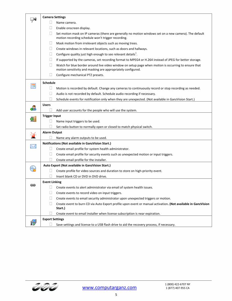
Camera Settings
Name camera.
Enable onscreen display.
Set motion mask on IP cameras (there are generally no motion windows set on a new camera). The default motion recording schedule won’t trigger recording.
Mask motion from irrelevant objects such as moving trees.
Create windows in relevant locations, such as doors and hallways.
Configure quality just high enough to see relevant details1.
If supported by the cameras, set recording format to MPEG4 or H.264 instead of JPEG for better storage.
Watch for blue border around live video window on setup page when motion is occurring to ensure that motion sensitivity and masking are appropriately configured.
Configure mechanical PTZ presets.
Schedule
Motion is recorded by default. Change any cameras to continuously record or stop recording as needed.
Audio is not recorded by default. Schedule audio recording if necessary.
Schedule events for notification only when they are unexpected. (Not available in GanzVision Start.)
Users
Add user accounts for the people who will use the system.
Trigger Input
Name input triggers to be used.
Set radio button to normally open or closed to match physical switch.
Alarm Output
Name any alarm outputs to be used.
Notifications (Not available in GanzVision Start.)
Create email profile for system health administrator.
Create email profile for security events such as unexpected motion or input triggers.
Create email profile for the installer.
Auto Export (Not available in GanzVision Start.)
Create profile for video sources and duration to store on high-priority event.
Insert blank CD or DVD in DVD drive.
Event Linking
Create events to alert administrator via email of system health issues.
Create events to record video on input triggers.
Create events to email security administrator upon unexpected triggers or motion.
Create event to burn CD via Auto Export profile upon event or manual activation. (Not available in GanzVision Start.)
Create event to email installer when license subscription is near expiration.
Export Settings
Save settings and license to a USB flash drive to aid the recovery process, if necessary.

www.computarganz.com
1 (800) 422-6707 NY 1 (877) 407-955 CA
6
Live Page (see Chapter 5)
Live
Create views as required by users for live viewing or multi-camera search and playback.
Install Client
Install the GanzVision Client on another computer and ensure that it can connect to the GanzVision Server using the static IP address and one of the configured user accounts.
Search Page (see Chapter 6)
Search*
Connect after 24 hours.
Connect after 7 days.
*Search to ensure cameras are not recording excessive amounts of motion; if they are, adjust motion sensitivity or windows/masks, or possibly adjust camera for low-light noise. Look at Storage page and extrapolate the storage duration to ensure that it meets requirements; if it does not, decrease frame rate, quality, or resolution.
www.computarganz.com
1 (800) 422-6707 NY 1 (877) 407-955 CA
7
2 Installing GanzVision Software on Third-Party Clients and Servers
Server Requirements
Hardware Requirements See the Computarganz website at http://www.computarganz.com/products/vmsrequirements.html for current minimum hardware requirements. Actual hardware requirements vary considerably based on each user’s application:
CPU requirements increase greatly when hosting multiple concurrent web clients.
The GanzVision server application requires a maximum of 4GB, although additional memory is required for the operating system, web hosting, or any other server applications.
The storage system is often the performance limitation because of the large amount of read and writes processed. Your storage system should be capable of sustained reads/writes at least twice the maximum data rate from all cameras. CBC (America) Corp highly recommends using RAID 5 or RAID 6 for all video storage to reduce the likelihood of catastrophic failure.
Enterprise-grade hard drives are highly recommended to handle constant video recording.
The server operating system and GanzVision software should be installed on a dedicated, mirrored operating system drive.
Servers should always be UPS-powered to avoid data corruption during power failure.
Operating System Requirements See Computarganz.com for minimum operating system requirements. In addition:
If automatic updating is enabled, your server might stop recording video when the operating-system restarts.
Anti-virus programs should scan only the operating system and GanzVision software drives. Virus scanning should be disabled on all video storage drives to avoid large decreases in drive performance.
Port blocking is not recommended because many edge devices use multiple or dynamic port assignment. MAC addressing requirements GanzVision software is licensed based on MAC addressing. Servers with teamed NICs or other arrangements that obscure the MAC require an additional USB-based NIC to provide a licensing MAC.
Networking
For the greatest system reliability and performance, the network administrator should observe the following best practices:
A dedicated VLAN and NIC port for all cameras.
A dedicated VLAN and NIC port for storage networks (if used).
A separate VLAN and NIC for all client connections.
Cameras and servers should use fixed IP addresses. Clients can use DHCP.
Camera-to-server network capacity should be twice to maximum video data rate.
Server-to-thick-client network capacity should be 1.5 times the maximum total data rate of all simultaneously viewed cameras.

www.computarganz.com
1 (800) 422-6707 NY 1 (877) 407-955 CA
8
Web Server
The GanzVision Web Services installer provides LightTPD as the default web service. You can find more information about this service at http://www.lighttpd.net. For systems where more than five to ten concurrent client connections are expected, you should upgrade to Apache web services. For more information, see https://www.computarganz.com/faq. As noted previously, web services increase server hardware requirements and can require installation on a dedicated web server. For additional information on configuring web services, see the knowledge base at https://www.computarganz.com/faq.
Server Software Installation
1. For Windows servers, download the latest server and web services software installation from http://computarganz.com/p.cfm?s=24&p=303
2. Using an administrator account, run the executable to start the installation wizard. 3. Configure the IP address, username, and password on all cameras by following the manufacturer’s
instructions. 4. Test connectivity to each camera with the ping command.
Client Software Installation
1. Download the latest client software from http://computarganz.com/p.cfm?s=24&p=303 2. Using an administrator account, run the executable to start the installation wizard. 3. Confirm connectivity with the server using the ping command and server IP address. If the client PC
cannot communicate with the server, contact the network administrator. 4. Start the GanzVision Client software and enter the configuration page. 5. In the site tree, select Add Systems. 6. Click New and enter the username admin, password admin256, and IP address (static) or hostname (fixed)
that was configured in previous steps. Click Apply. If the new server appears in the system list table with a status of Connected, the initial server configuration is complete. If the server does NOT connect, but server connectivity was confirmed in previous steps, ensure that the PC anti-virus software is not blocking communications with the server IP addresses and ports.
7. Proceed to Chapter 4 to start GanzVision server configuration.

www.computarganz.com
1 (800) 422-6707 NY 1 (877) 407-955 CA
9
3 GanzVision Software Overview
Client/Server Architecture
GanzVision software is based on a client/server architecture in which every computer is a client, server, or client/server combination. These configurations are defined as follows:
A client computer provides access to a remote service on another computer over a TCP/IP network. The GanzVision Client software is a thick client, and the web browser is a thin client.
A server computer provides services to client computers over the TCP/IP network. A GanzVision server receives and stores video from cameras; provides audio, video, and data as requested by thick clients; and hosts a web server (if enabled) for thin clients. The GanzVision Server software does not have a graphical user interface; only the client software allows interaction. A server can serve multiple simultaneous client connections, within hardware limitations.
A client/server combination simultaneously operates client and server software. A loopback TCP/IP address of “localhost” (127.0.0.1) allows the client software to communicate with the server software on the same computer. GanzVision servers are configured at the factory as a client/server combination to provide a convenient initial configuration experience.
www.computarganz.com
1 (800) 422-6707 NY 1 (877) 407-955 CA
10
Logging In
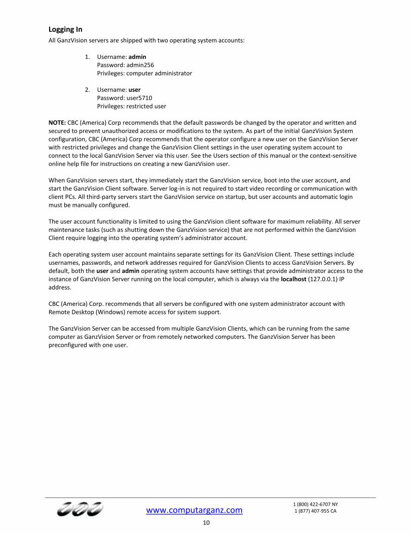
All GanzVision servers are shipped with two operating system accounts:
1. Username: admin Password: admin256 Privileges: computer administrator
2. Username: user Password: user5710 Privileges: restricted user
NOTE: CBC (America) Corp recommends that the default passwords be changed by the operator and written and secured to prevent unauthorized access or modifications to the system. As part of the initial GanzVision System configuration, CBC (America) Corp recommends that the operator configure a new user on the GanzVision Server with restricted privileges and change the GanzVision Client settings in the user operating system account to connect to the local GanzVision Server via this user. See the Users section of this manual or the context-sensitive online help file for instructions on creating a new GanzVision user.
When GanzVision servers start, they immediately start the GanzVision service, boot into the user account, and start the GanzVision Client software. Server log-in is not required to start video recording or communication with client PCs. All third-party servers start the GanzVision service on startup, but user accounts and automatic login must be manually configured. The user account functionality is limited to using the GanzVision client software for maximum reliability. All server maintenance tasks (such as shutting down the GanzVision service) that are not performed within the GanzVision Client require logging into the operating system’s administrator account. Each operating system user account maintains separate settings for its GanzVision Client. These settings include usernames, passwords, and network addresses required for GanzVision Clients to access GanzVision Servers. By default, both the user and admin operating system accounts have settings that provide administrator access to the instance of GanzVision Server running on the local computer, which is always via the localhost (127.0.0.1) IP address. CBC (America) Corp. recommends that all servers be configured with one system administrator account with Remote Desktop (Windows) remote access for system support.
The GanzVision Server can be accessed from multiple GanzVision Clients, which can be running from the same computer as GanzVision Server or from remotely networked computers. The GanzVision Server has been preconfigured with one user.
www.computarganz.com
1 (800) 422-6707 NY 1 (877) 407-955 CA
11
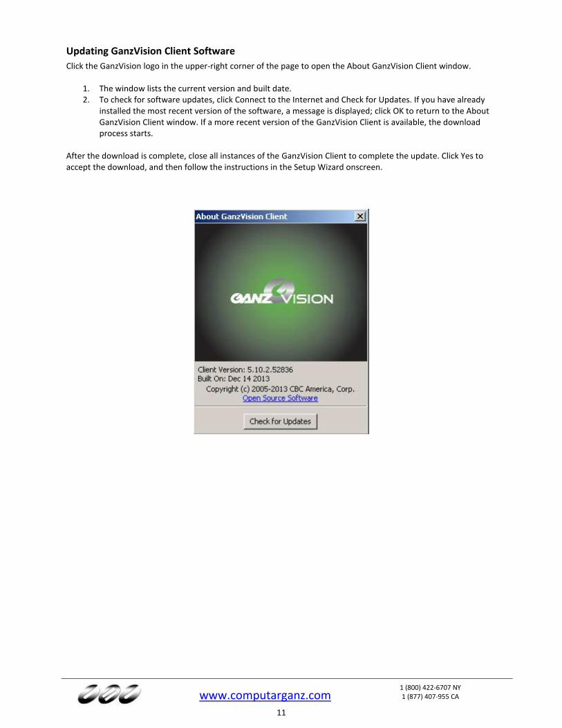
Updating GanzVision Client Software
Click the GanzVision logo in the upper-right corner of the page to open the About GanzVision Client window.
1. The window lists the current version and built date. 2. To check for software updates, click Connect to the Internet and Check for Updates. If you have already
installed the most recent version of the software, a message is displayed; click OK to return to the About GanzVision Client window. If a more recent version of the GanzVision Client is available, the download process starts.
After the download is complete, close all instances of the GanzVision Client to complete the update. Click Yes to accept the download, and then follow the instructions in the Setup Wizard onscreen.
www.computarganz.com
1 (800) 422-6707 NY 1 (877) 407-955 CA
12
Main Pages
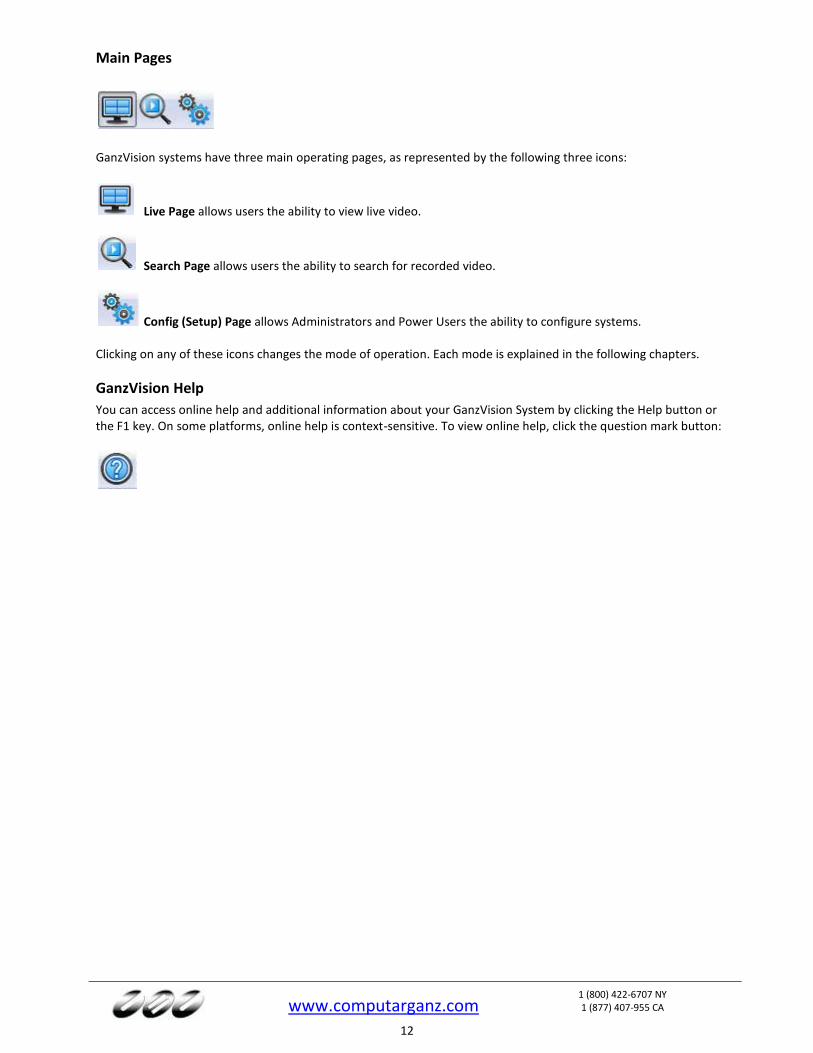
GanzVision systems have three main operating pages, as represented by the following three icons:
Live Page allows users the ability to view live video.
Search Page allows users the ability to search for recorded video.
Config (Setup) Page allows Administrators and Power Users the ability to configure systems. Clicking on any of these icons changes the mode of operation. Each mode is explained in the following chapters.
GanzVision Help
You can access online help and additional information about your GanzVision System by clicking the Help button or the F1 key. On some platforms, online help is context-sensitive. To view online help, click the question mark button:
www.computarganz.com
1 (800) 422-6707 NY 1 (877) 407-955 CA
13
4 Config (Setup) Page Overview
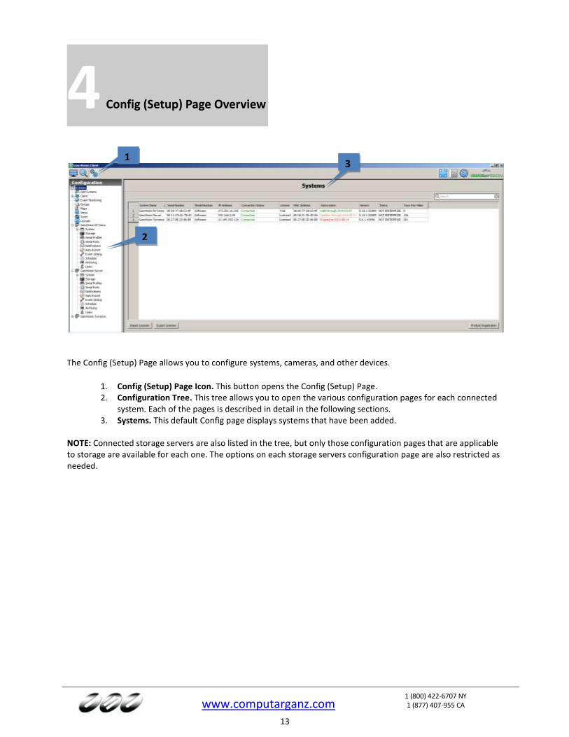
The Config (Setup) Page allows you to configure systems, cameras, and other devices.
1. Config (Setup) Page Icon. This button opens the Config (Setup) Page. 2. Configuration Tree. This tree allows you to open the various configuration pages for each connected
system. Each of the pages is described in detail in the following sections. 3. Systems. This default Config page displays systems that have been added.
NOTE: Connected storage servers are also listed in the tree, but only those configuration pages that are applicable to storage are available for each one. The options on each storage servers configuration page are also restricted as needed.
1 3
2
www.computarganz.com
1 (800) 422-6707 NY 1 (877) 407-955 CA
14
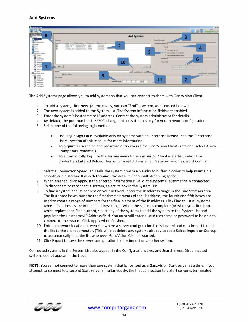
Add Systems
The Add Systems page allows you to add systems so that you can connect to them with GanzVision Client.
1. To add a system, click New. (Alternatively, you can “find” a system, as discussed below.) 2. The new system is added to the System List. The System Information fields are enabled. 3. Enter the system’s hostname or IP address. Contact the system administrator for details. 4. By default, the port number is 22609; change this only if necessary for your network configuration. 5. Select one of the following login methods:
Use Single Sign-On is available only on systems with an Enterprise license. See the “Enterprise Users” section of this manual for more information.
To require a username and password entry every time GanzVision Client is started, select Always Prompt for Credentials.
To automatically log in to the system every time GanzVision Client is started, select Use Credentials Entered Below. Then enter a valid Username, Password, and Password Confirm.
6. Select a Connection Speed. This tells the system how much audio to buffer in order to help maintain a smooth audio stream. It also determines the default video multistreaming speed.
7. When finished, click Apply. If the entered information is valid, the system is automatically connected. 8. To disconnect or reconnect a system, select its box in the System List. 9. To find a system and its address on your network, enter the IP address range in the Find Systems area.
The first three boxes must be the first three elements of the IP address; the fourth and fifth boxes are used to create a range of numbers for the final element of the IP address. Click Find to list all systems whose IP addresses are in the IP address range. When the search is complete (or when you click Stop, which replaces the Find button), select any of the systems to add the system to the System List and populate the Hostname/IP Address field. You must still enter a valid username or password to be able to connect to the system. Click Apply when finished.
10. Enter a network location or web site where a server configuration file is located and click Import to load the list to the client computer. (This will not delete any systems already added.) Select Import on Startup to automatically load the list whenever GanzVision Client is started.
11. Click Export to save the server configuration file for import on another system.
Connected systems in the System List also appear in the Configuration, Live, and Search trees. Disconnected systems do not appear in the trees. NOTE: You cannot connect to more than one system that is licensed as a GanzVision Start server at a time. If you attempt to connect to a second Start server simultaneously, the first connection to a Start server is terminated.
1
3
4 5
6
76
8
9
2
10
11
www.computarganz.com
1 (800) 422-6707 NY 1 (877) 407-955 CA
15
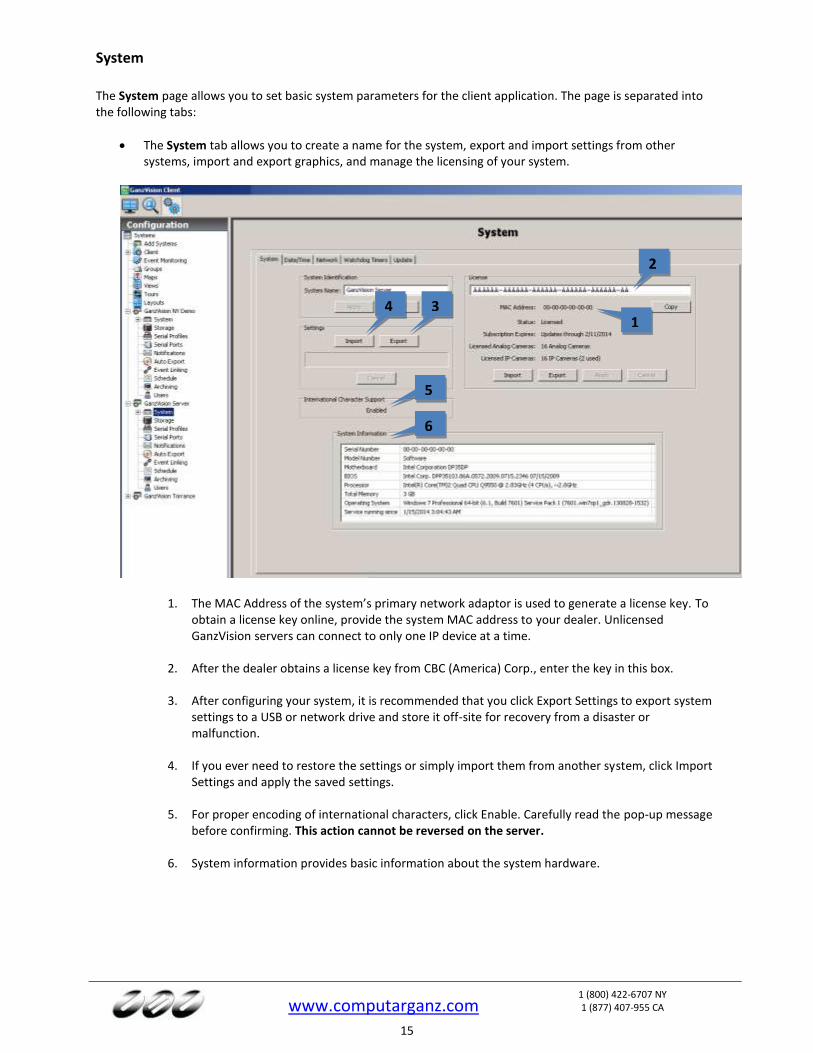
System
The System page allows you to set basic system parameters for the client application. The page is separated into the following tabs:
The System tab allows you to create a name for the system, export and import settings from other systems, import and export graphics, and manage the licensing of your system.
1. The MAC Address of the system’s primary network adaptor is used to generate a license key. To obtain a license key online, provide the system MAC address to your dealer. Unlicensed GanzVision servers can connect to only one IP device at a time.
2. After the dealer obtains a license key from CBC (America) Corp., enter the key in this box.
3. After configuring your system, it is recommended that you click Export Settings to export system settings to a USB or network drive and store it off-site for recovery from a disaster or malfunction.
4. If you ever need to restore the settings or simply import them from another system, click Import Settings and apply the saved settings.
5. For proper encoding of international characters, click Enable. Carefully read the pop-up message before confirming. This action cannot be reversed on the server.
6. System information provides basic information about the system hardware.
2
1
3 4
6
5

www.computarganz.com
1 (800) 422-6707 NY 1 (877) 407-955 CA
16
The Date/Time tab displays the GanzVision server’s time information.
1. Select the time zone and daylight saving time (DST) information for the server’s location.
2. On systems with Internet access, select Enable Time Server and enter a valid Internet time server. On systems without Internet access, select Enable Time Server and enter an internal time server (see your network administrator for more information).
3. If the IP cameras on the network need to synchronize with a time server other than the GanzVision server, select Enable Override and enter the server address.
1
2
3
www.computarganz.com
1 (800) 422-6707 NY 1 (877) 407-955 CA
17
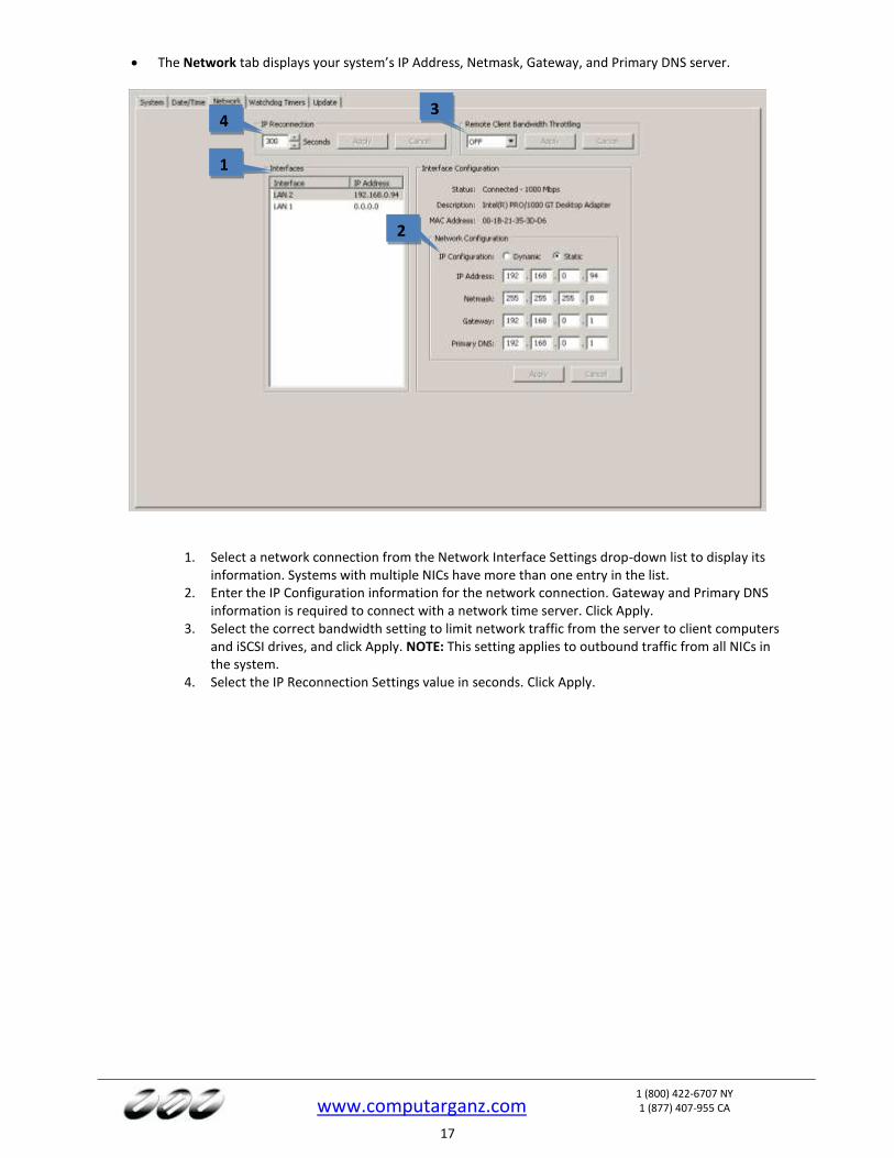
The Network tab displays your system’s IP Address, Netmask, Gateway, and Primary DNS server.
1. Select a network connection from the Network Interface Settings drop-down list to display its
information. Systems with multiple NICs have more than one entry in the list. 2. Enter the IP Configuration information for the network connection. Gateway and Primary DNS
information is required to connect with a network time server. Click Apply. 3. Select the correct bandwidth setting to limit network traffic from the server to client computers
and iSCSI drives, and click Apply. NOTE: This setting applies to outbound traffic from all NICs in the system.
4. Select the IP Reconnection Settings value in seconds. Click Apply.
1
2
3 4
www.computarganz.com
1 (800) 422-6707 NY 1 (877) 407-955 CA
18
The Active Directory/LDAP tab appears on the System page on systems with an Enterprise license. For more information, see the LDAP integration document appropriate for your platform found at https://www.Computarganz.com/downloads/LDAP/index.html.
The Watchdog Timer tab displays information about the system’s factory-installed watchdogs, if available. The watchdogs can restart systems or capture cards if they lock up. The information on the tab is not configurable.
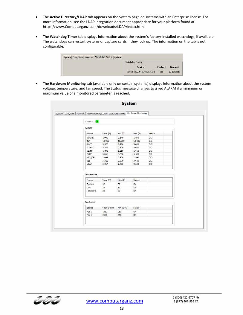
The Hardware Monitoring tab (available only on certain systems) displays information about the system voltage, temperature, and fan speed. The Status message changes to a red ALARM if a minimum or maximum value of a monitored parameter is reached.
www.computarganz.com
1 (800) 422-6707 NY 1 (877) 407-955 CA
19
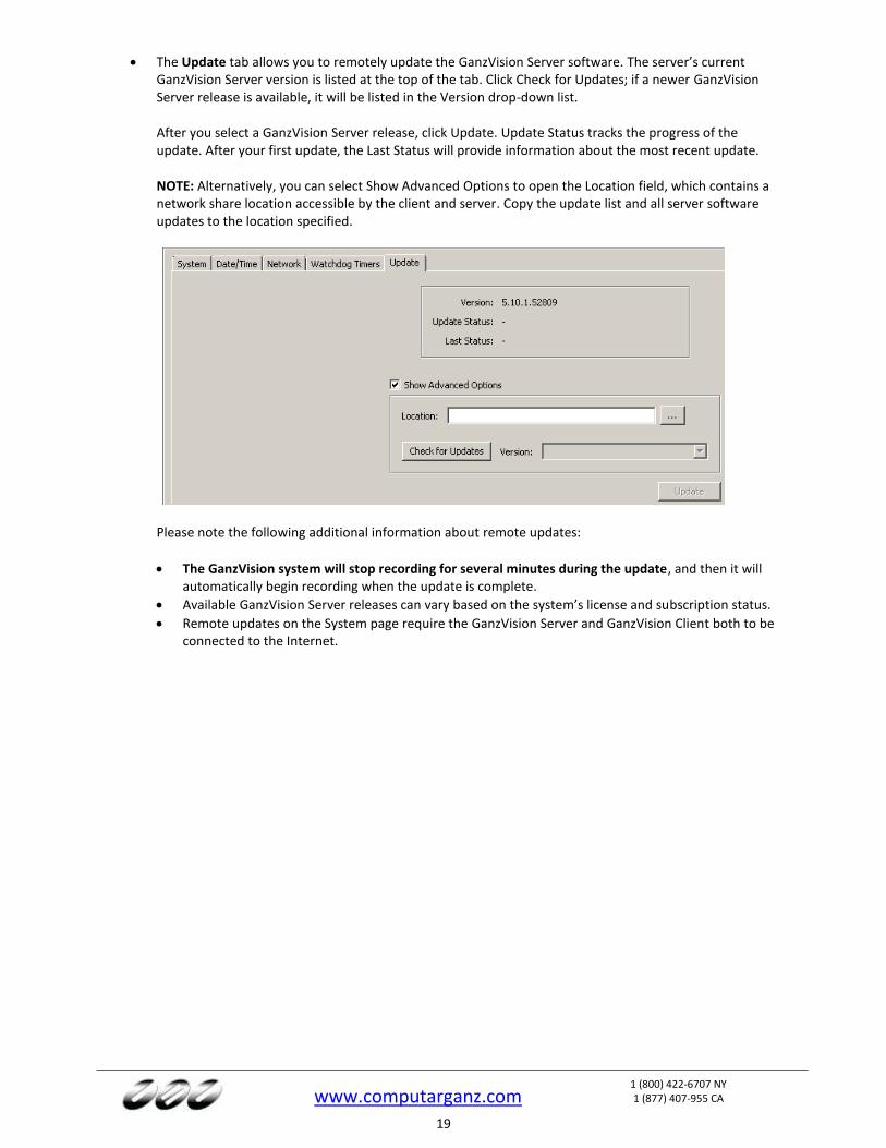
The Update tab allows you to remotely update the GanzVision Server software. The server’s current GanzVision Server version is listed at the top of the tab. Click Check for Updates; if a newer GanzVision Server release is available, it will be listed in the Version drop-down list. After you select a GanzVision Server release, click Update. Update Status tracks the progress of the update. After your first update, the Last Status will provide information about the most recent update. NOTE: Alternatively, you can select Show Advanced Options to open the Location field, which contains a network share location accessible by the client and server. Copy the update list and all server software updates to the location specified.
Please note the following additional information about remote updates:
The GanzVision system will stop recording for several minutes during the update, and then it will automatically begin recording when the update is complete.
Available GanzVision Server releases can vary based on the system’s license and subscription status.
Remote updates on the System page require the GanzVision Server and GanzVision Client both to be connected to the Internet.
www.computarganz.com
1 (800) 422-6707 NY 1 (877) 407-955 CA
20
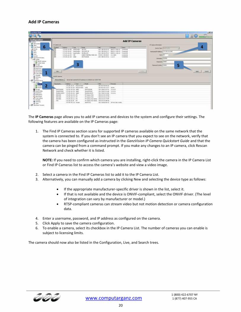
Add IP Cameras
The IP Cameras page allows you to add IP cameras and devices to the system and configure their settings. The following features are available on the IP Cameras page:
1. The Find IP Cameras section scans for supported IP cameras available on the same network that the system is connected to. If you don’t see an IP camera that you expect to see on the network, verify that the camera has been configured as instructed in the GanzVision IP Camera Quickstart Guide and that the camera can be pinged from a command prompt. If you make any changes to an IP camera, click Rescan Network and check whether it is listed. NOTE: If you need to confirm which camera you are installing, right-click the camera in the IP Camera List or Find IP Cameras list to access the camera’s website and view a video image.
2. Select a camera in the Find IP Cameras list to add it to the IP Camera List. 3. Alternatively, you can manually add a camera by clicking New and selecting the device type as follows:
If the appropriate manufacturer-specific driver is shown in the list, select it.
If that is not available and the device is ONVIF-compliant, select the ONVIF driver. (The level of integration can vary by manufacturer or model.)
RTSP-compliant cameras can stream video but not motion detection or camera configuration data.
4. Enter a username, password, and IP address as configured on the camera. 5. Click Apply to save the camera configuration. 6. To enable a camera, select its checkbox in the IP Camera List. The number of cameras you can enable is
subject to licensing limits.
The camera should now also be listed in the Configuration, Live, and Search trees.
1
2
3
4
5
6
www.computarganz.com
1 (800) 422-6707 NY 1 (877) 407-955 CA
21
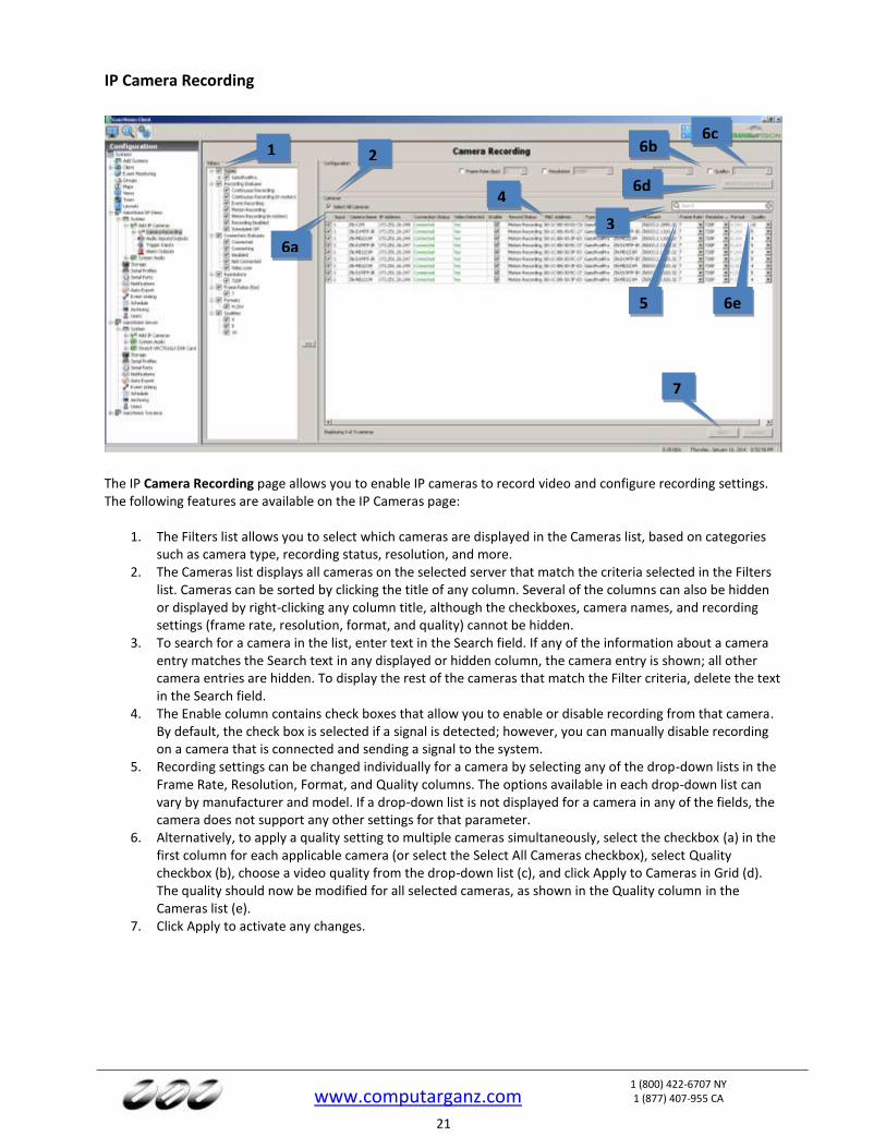
IP Camera Recording
The IP Camera Recording page allows you to enable IP cameras to record video and configure recording settings. The following features are available on the IP Cameras page:
1. The Filters list allows you to select which cameras are displayed in the Cameras list, based on categories such as camera type, recording status, resolution, and more.
2. The Cameras list displays all cameras on the selected server that match the criteria selected in the Filters list. Cameras can be sorted by clicking the title of any column. Several of the columns can also be hidden or displayed by right-clicking any column title, although the checkboxes, camera names, and recording settings (frame rate, resolution, format, and quality) cannot be hidden.
3. To search for a camera in the list, enter text in the Search field. If any of the information about a camera entry matches the Search text in any displayed or hidden column, the camera entry is shown; all other camera entries are hidden. To display the rest of the cameras that match the Filter criteria, delete the text in the Search field.
4. The Enable column contains check boxes that allow you to enable or disable recording from that camera. By default, the check box is selected if a signal is detected; however, you can manually disable recording on a camera that is connected and sending a signal to the system.
5. Recording settings can be changed individually for a camera by selecting any of the drop-down lists in the Frame Rate, Resolution, Format, and Quality columns. The options available in each drop-down list can vary by manufacturer and model. If a drop-down list is not displayed for a camera in any of the fields, the camera does not support any other settings for that parameter.
6. Alternatively, to apply a quality setting to multiple cameras simultaneously, select the checkbox (a) in the first column for each applicable camera (or select the Select All Cameras checkbox), select Quality checkbox (b), choose a video quality from the drop-down list (c), and click Apply to Cameras in Grid (d). The quality should now be modified for all selected cameras, as shown in the Quality column in the Cameras list (e).
7. Click Apply to activate any changes.
1 2
4
5
6a
7
6b 6c
6d
6e
3
www.computarganz.com
1 (800) 422-6707 NY 1 (877) 407-955 CA
22
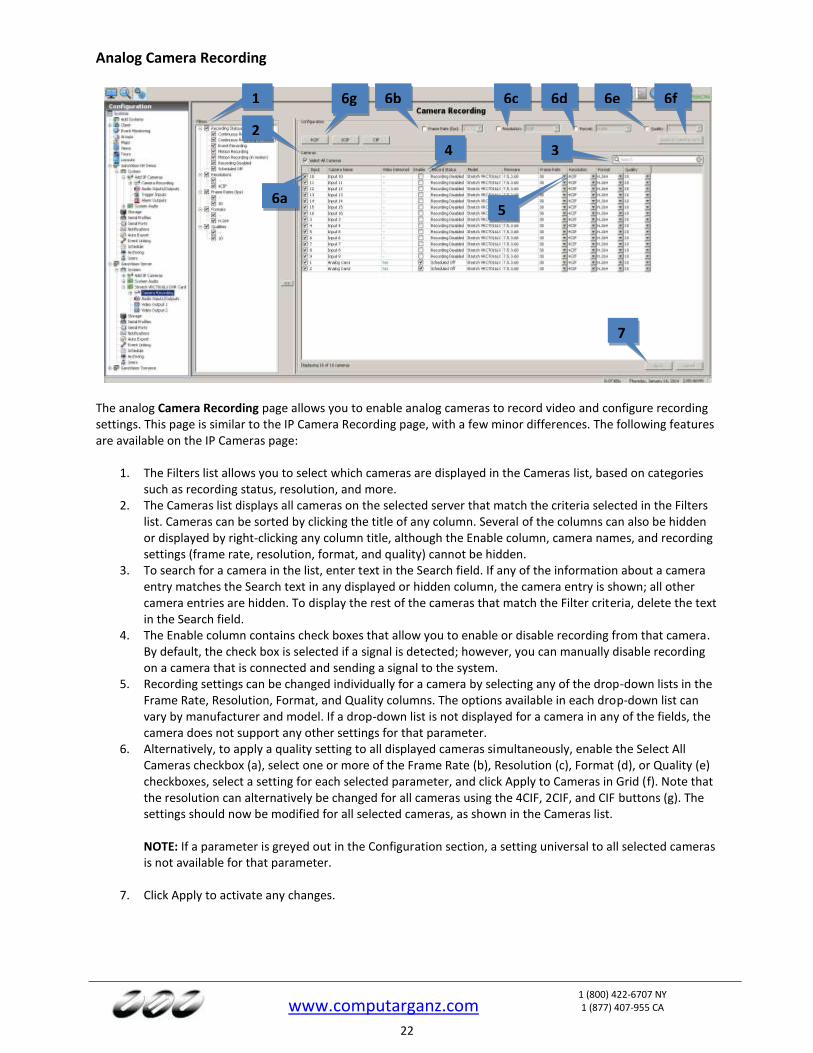
Analog Camera Recording
The analog Camera Recording page allows you to enable analog cameras to record video and configure recording settings. This page is similar to the IP Camera Recording page, with a few minor differences. The following features are available on the IP Cameras page:
1. The Filters list allows you to select which cameras are displayed in the Cameras list, based on categories such as recording status, resolution, and more.
2. The Cameras list displays all cameras on the selected server that match the criteria selected in the Filters list. Cameras can be sorted by clicking the title of any column. Several of the columns can also be hidden or displayed by right-clicking any column title, although the Enable column, camera names, and recording settings (frame rate, resolution, format, and quality) cannot be hidden.
3. To search for a camera in the list, enter text in the Search field. If any of the information about a camera entry matches the Search text in any displayed or hidden column, the camera entry is shown; all other camera entries are hidden. To display the rest of the cameras that match the Filter criteria, delete the text in the Search field.
4. The Enable column contains check boxes that allow you to enable or disable recording from that camera. By default, the check box is selected if a signal is detected; however, you can manually disable recording on a camera that is connected and sending a signal to the system.
5. Recording settings can be changed individually for a camera by selecting any of the drop-down lists in the Frame Rate, Resolution, Format, and Quality columns. The options available in each drop-down list can vary by manufacturer and model. If a drop-down list is not displayed for a camera in any of the fields, the camera does not support any other settings for that parameter.
6. Alternatively, to apply a quality setting to all displayed cameras simultaneously, enable the Select All Cameras checkbox (a), select one or more of the Frame Rate (b), Resolution (c), Format (d), or Quality (e) checkboxes, select a setting for each selected parameter, and click Apply to Cameras in Grid (f). Note that the resolution can alternatively be changed for all cameras using the 4CIF, 2CIF, and CIF buttons (g). The settings should now be modified for all selected cameras, as shown in the Cameras list.
NOTE: If a parameter is greyed out in the Configuration section, a setting universal to all selected cameras is not available for that parameter.
7. Click Apply to activate any changes.
1
3 4
5
7
2
6a
6b 6c 6d 6e 6f 6g
www.computarganz.com
1 (800) 422-6707 NY 1 (877) 407-955 CA
23
Camera Settings
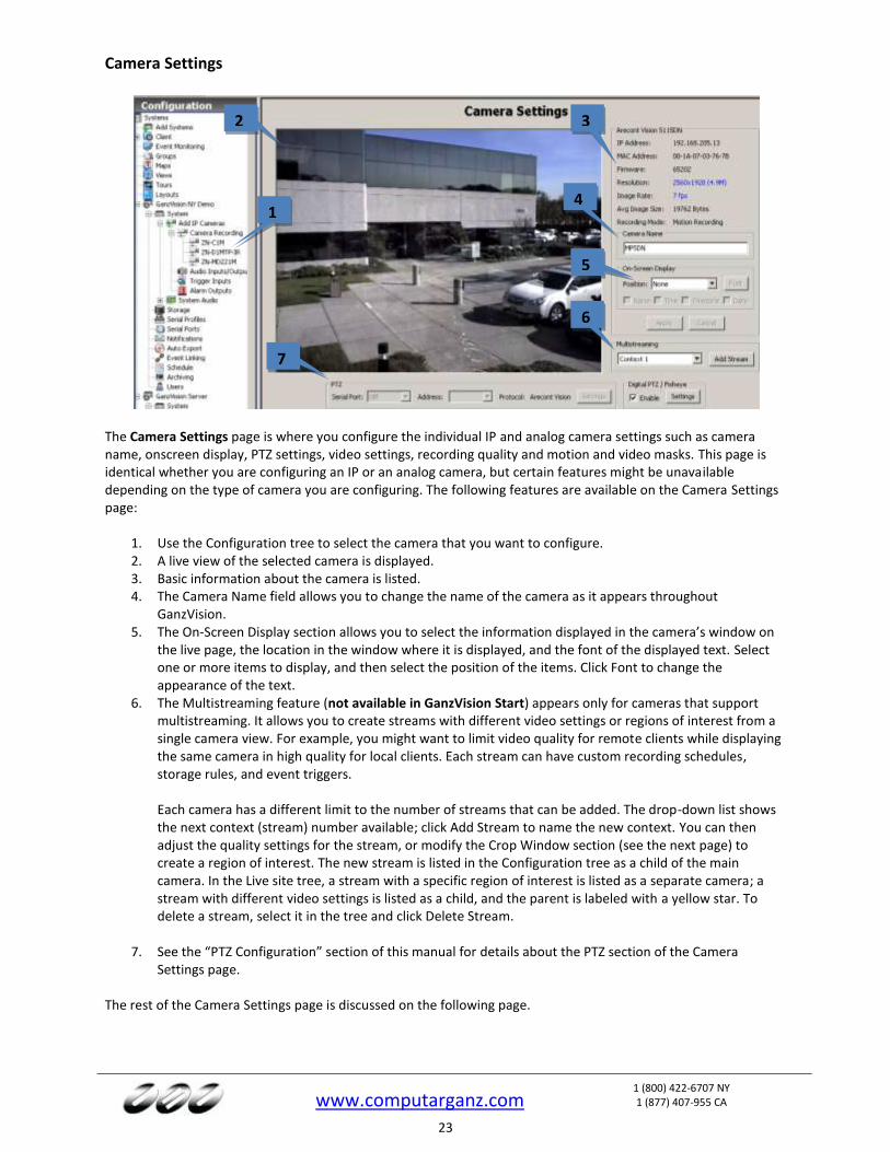
The Camera Settings page is where you configure the individual IP and analog camera settings such as camera name, onscreen display, PTZ settings, video settings, recording quality and motion and video masks. This page is identical whether you are configuring an IP or an analog camera, but certain features might be unavailable depending on the type of camera you are configuring. The following features are available on the Camera Settings page:
1. Use the Configuration tree to select the camera that you want to configure. 2. A live view of the selected camera is displayed. 3. Basic information about the camera is listed. 4. The Camera Name field allows you to change the name of the camera as it appears throughout
GanzVision. 5. The On-Screen Display section allows you to select the information displayed in the camera’s window on
the live page, the location in the window where it is displayed, and the font of the displayed text. Select one or more items to display, and then select the position of the items. Click Font to change the appearance of the text.
6. The Multistreaming feature (not available in GanzVision Start) appears only for cameras that support multistreaming. It allows you to create streams with different video settings or regions of interest from a single camera view. For example, you might want to limit video quality for remote clients while displaying the same camera in high quality for local clients. Each stream can have custom recording schedules, storage rules, and event triggers. Each camera has a different limit to the number of streams that can be added. The drop-down list shows the next context (stream) number available; click Add Stream to name the new context. You can then adjust the quality settings for the stream, or modify the Crop Window section (see the next page) to create a region of interest. The new stream is listed in the Configuration tree as a child of the main camera. In the Live site tree, a stream with a specific region of interest is listed as a separate camera; a stream with different video settings is listed as a child, and the parent is labeled with a yellow star. To delete a stream, select it in the tree and click Delete Stream.
7. See the “PTZ Configuration” section of this manual for details about the PTZ section of the Camera Settings page.
The rest of the Camera Settings page is discussed on the following page.
2 3
5
7
1 4
6
www.computarganz.com
1 (800) 422-6707 NY 1 (877) 407-955 CA
24
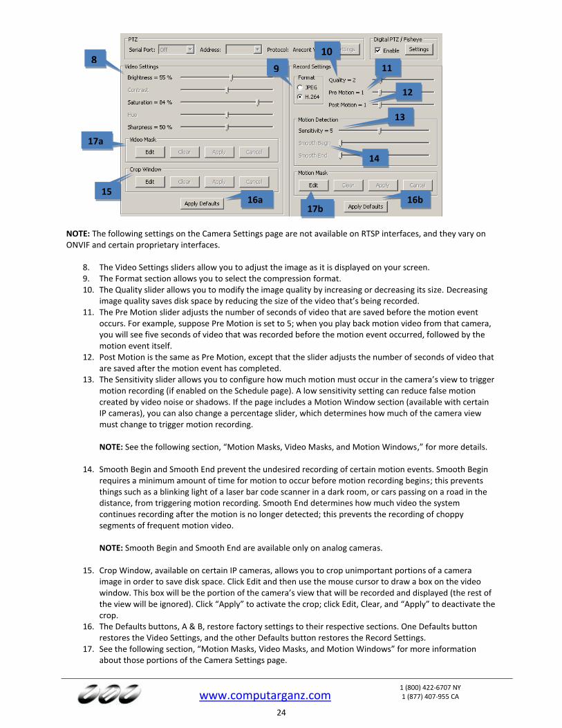
NOTE: The following settings on the Camera Settings page are not available on RTSP interfaces, and they vary on ONVIF and certain proprietary interfaces.
8. The Video Settings sliders allow you to adjust the image as it is displayed on your screen. 9. The Format section allows you to select the compression format. 10. The Quality slider allows you to modify the image quality by increasing or decreasing its size. Decreasing
image quality saves disk space by reducing the size of the video that’s being recorded. 11. The Pre Motion slider adjusts the number of seconds of video that are saved before the motion event
occurs. For example, suppose Pre Motion is set to 5; when you play back motion video from that camera, you will see five seconds of video that was recorded before the motion event occurred, followed by the motion event itself.
12. Post Motion is the same as Pre Motion, except that the slider adjusts the number of seconds of video that are saved after the motion event has completed.
13. The Sensitivity slider allows you to configure how much motion must occur in the camera’s view to trigger motion recording (if enabled on the Schedule page). A low sensitivity setting can reduce false motion created by video noise or shadows. If the page includes a Motion Window section (available with certain IP cameras), you can also change a percentage slider, which determines how much of the camera view must change to trigger motion recording.
NOTE: See the following section, “Motion Masks, Video Masks, and Motion Windows,” for more details.
14. Smooth Begin and Smooth End prevent the undesired recording of certain motion events. Smooth Begin
requires a minimum amount of time for motion to occur before motion recording begins; this prevents things such as a blinking light of a laser bar code scanner in a dark room, or cars passing on a road in the distance, from triggering motion recording. Smooth End determines how much video the system continues recording after the motion is no longer detected; this prevents the recording of choppy segments of frequent motion video.
NOTE: Smooth Begin and Smooth End are available only on analog cameras.
15. Crop Window, available on certain IP cameras, allows you to crop unimportant portions of a camera
image in order to save disk space. Click Edit and then use the mouse cursor to draw a box on the video window. This box will be the portion of the camera’s view that will be recorded and displayed (the rest of the view will be ignored). Click “Apply” to activate the crop; click Edit, Clear, and “Apply” to deactivate the crop.
16. The Defaults buttons, A & B, restore factory settings to their respective sections. One Defaults button restores the Video Settings, and the other Defaults button restores the Record Settings.
17. See the following section, “Motion Masks, Video Masks, and Motion Windows” for more information about those portions of the Camera Settings page.
8 9 11
10
12
13
17b
14
16a 16b
17a
15

www.computarganz.com
1 (800) 422-6707 NY 1 (877) 407-955 CA
25
IMPORTANT NOTE
Many IP camera settings that are not available in the GanzVision software can be accessed through the camera’s web page. To view an IP camera’s web page, click the hyperlink in the IP Address field. If you don’t see a hyperlink beside the IP Address field, it could be for one of two reasons:
A. You are not logged in to the operating system with administrative privileges. You must log in to operating system account with administrative privileges to access the hyperlink.
B. Your client computer is not located on the same IP subnet as the IP camera. This could occur if you are using the client from a home computer to access a server at your office, for example. This restriction should cause few issues because camera website settings are typically changed only during initial configuration.

www.computarganz.com
1 (800) 422-6707 NY 1 (877) 407-955 CA
26
Motion Masks, Video Masks, and Motion Windows
The following types of masks can be created on cameras connected to a GanzVision system:
A Motion Mask is an area of a video window where motion is ignored
A Motion Window is an area of a video window where motion is monitored (and the remainder of the screen is essentially masked).
A Video Mask is used to block an area of a camera’s view so that it cannot be seen onscreen in live or recorded video.
NOTE: The type of mask available varies by camera. A motion mask reduces unwanted recording by ignoring motion events that occur in certain areas of an image. For example, if a camera is pointed at a room that has a moving ceiling fan in the field of view, you can avoid continuous motion recording by masking out the fan while still recording motion that occurs in the rest of the camera’s field of view. Motion masks save storage space, extend recording time, and make it easier to visually see motion events on the video timeline on the Search Page. A motion window is simply the opposite of a motion mask. To create a motion mask or motion window, complete the following steps:
1. On the Camera Settings page, click Edit in the Motion Mask or Motion Window section. This displays a blue motion grid over live video from the camera.
2. Draw the mask directly in the grid. You can either individually click each rectangle to create the mask or window, or you can left-click while dragging the cursor across multiple rectangles.
3. Click Apply to enable the motion mask or motion window. To delete a motion mask or window, click Edit, click Clear, and click Apply.
1
2
3
www.computarganz.com
1 (800) 422-6707 NY 1 (877) 407-955 CA
27
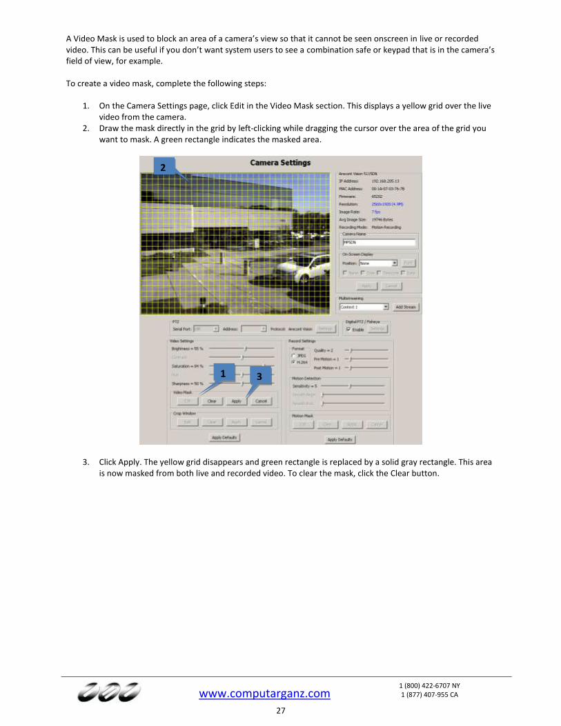
A Video Mask is used to block an area of a camera’s view so that it cannot be seen onscreen in live or recorded video. This can be useful if you don’t want system users to see a combination safe or keypad that is in the camera’s field of view, for example. To create a video mask, complete the following steps:
1. On the Camera Settings page, click Edit in the Video Mask section. This displays a yellow grid over the live video from the camera.
2. Draw the mask directly in the grid by left-clicking while dragging the cursor over the area of the grid you want to mask. A green rectangle indicates the masked area.
3. Click Apply. The yellow grid disappears and green rectangle is replaced by a solid gray rectangle. This area is now masked from both live and recorded video. To clear the mask, click the Clear button.
1
2
3

www.computarganz.com
1 (800) 422-6707 NY 1 (877) 407-955 CA
28
Serial Profiles
The Serial Profiles page enables the GanzVision server to integrate with serial data devices such as point-of-sale (POS) and bank machine systems.
1. To view an existing profile, select it from the list. 2. To add a new profile, click the New below the list of profiles. 3. Enter a unique name in the Profile Name field in the Current Profile Properties box. 4. The SOT Marker, or Start of Transaction Marker, tells the GanzVision System when the transaction has
started. For example, you could enter the first line shown on a receipt. This entry is case-sensitive. 5. The EOT Marker, or End of Transaction Marker, tells the GanzVision System when the transaction has
ended. For example, you could enter the last line shown on a receipt. This entry is case-sensitive. 6. The Font button allows you to select the font you want to be displayed on the “Live” view. 7. Event Key Words (not available in GanzVision Start) allows you to set alarms that will be triggered through
key words on a receipt after you link the profile through the Event Linking system. 8. The Line Masks and String Replacements tabs are discussed on the following page. 9. The Data Retention section allows you to select the number of days that serial data is stored before it is
automatically deleted. 10. When finished, click Apply.
NOTES: You can require case sensitivity for all strings or all key words by selecting the appropriate Case Sensitive option under each list. To enter the ESC (0x1b) ASCII character as the SOT, EOT, mask, or key word, enter “/x1b” in the appropriate field. CR, LF, or 80 characters terminates a line. You have now created the new serial profile. If you entered any data in the Event Key Words box, you must link the profile to the appropriate Action through the Event Linking page, selecting Serial Profile as the Event Type.
1
2
3
4
5 6
7
8
9
10
www.computarganz.com
1 (800) 422-6707 NY 1 (877) 407-955 CA
29
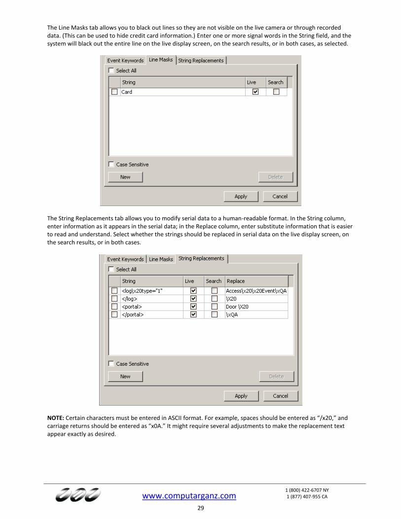
The Line Masks tab allows you to black out lines so they are not visible on the live camera or through recorded data. (This can be used to hide credit card information.) Enter one or more signal words in the String field, and the system will black out the entire line on the live display screen, on the search results, or in both cases, as selected.
The String Replacements tab allows you to modify serial data to a human-readable format. In the String column, enter information as it appears in the serial data; in the Replace column, enter substitute information that is easier to read and understand. Select whether the strings should be replaced in serial data on the live display screen, on the search results, or in both cases.
NOTE: Certain characters must be entered in ASCII format. For example, spaces should be entered as “/x20,” and carriage returns should be entered as “x0A.” It might require several adjustments to make the replacement text appear exactly as desired.
www.computarganz.com
1 (800) 422-6707 NY 1 (877) 407-955 CA
30
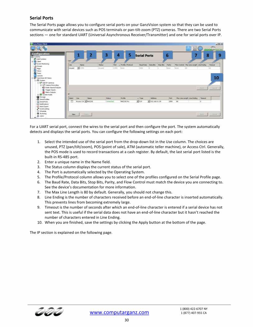
Serial Ports
The Serial Ports page allows you to configure serial ports on your GanzVision system so that they can be used to communicate with serial devices such as POS terminals or pan-tilt-zoom (PTZ) cameras. There are two Serial Ports sections — one for standard UART (Universal Asynchronous Receiver/Transmitter) and one for serial ports over IP.
For a UART serial port, connect the wires to the serial port and then configure the port. The system automatically detects and displays the serial ports. You can configure the following settings on each port:
1. Select the intended use of the serial port from the drop-down list in the Use column. The choices are unused, PTZ (pan/tilt/zoom), POS (point of sale), ATM (automatic teller machine), or Access Ctrl. Generally, the POS mode is used to record transactions at a cash register. By default, the last serial port listed is the built-in RS-485 port.
2. Enter a unique name in the Name field. 3. The Status column displays the current status of the serial port. 4. The Port is automatically selected by the Operating System. 5. The Profile/Protocol column allows you to select one of the profiles configured on the Serial Profile page. 6. The Baud Rate, Data Bits, Stop Bits, Parity, and Flow Control must match the device you are connecting to.
See the device’s documentation for more information. 7. The Max Line Length is 80 by default. Generally, you should not change this. 8. Line Ending is the number of characters received before an end-of-line character is inserted automatically.
This prevents lines from becoming extremely large. 9. Timeout is the number of seconds after which an end-of-line character is entered if a serial device has not
sent text. This is useful if the serial data does not have an end-of-line character but it hasn’t reached the number of characters entered in Line Ending.
10. When you are finished, save the settings by clicking the Apply button at the bottom of the page. The IP section is explained on the following page.
1 2 31
4 5 6 7
10
8 9
www.computarganz.com
1 (800) 422-6707 NY 1 (877) 407-955 CA
31
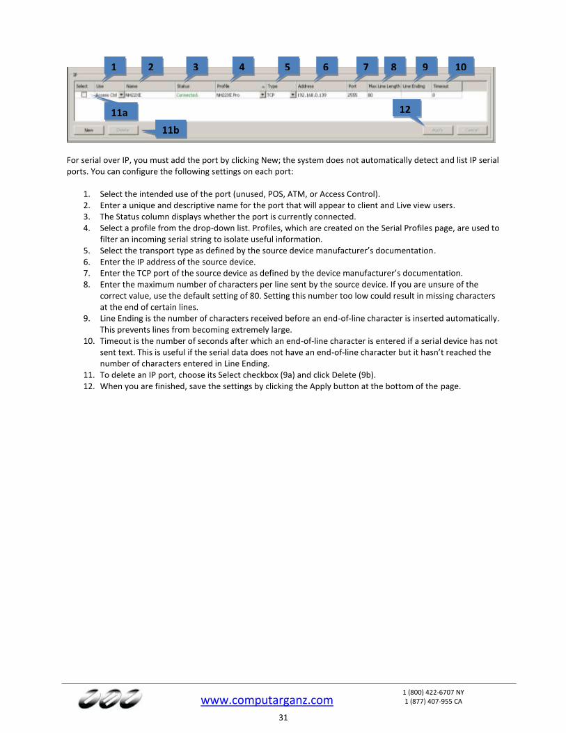
For serial over IP, you must add the port by clicking New; the system does not automatically detect and list IP serial ports. You can configure the following settings on each port:
1. Select the intended use of the port (unused, POS, ATM, or Access Control). 2. Enter a unique and descriptive name for the port that will appear to client and Live view users. 3. The Status column displays whether the port is currently connected. 4. Select a profile from the drop-down list. Profiles, which are created on the Serial Profiles page, are used to
filter an incoming serial string to isolate useful information. 5. Select the transport type as defined by the source device manufacturer’s documentation. 6. Enter the IP address of the source device. 7. Enter the TCP port of the source device as defined by the device manufacturer’s documentation. 8. Enter the maximum number of characters per line sent by the source device. If you are unsure of the
correct value, use the default setting of 80. Setting this number too low could result in missing characters at the end of certain lines.
9. Line Ending is the number of characters received before an end-of-line character is inserted automatically. This prevents lines from becoming extremely large.
10. Timeout is the number of seconds after which an end-of-line character is entered if a serial device has not sent text. This is useful if the serial data does not have an end-of-line character but it hasn’t reached the number of characters entered in Line Ending.
11. To delete an IP port, choose its Select checkbox (9a) and click Delete (9b). 12. When you are finished, save the settings by clicking the Apply button at the bottom of the page.
1 2 3 4 5 6 7 8
12 11aa 11b
a
9 10
www.computarganz.com
1 (800) 422-6707 NY 1 (877) 407-955 CA
32
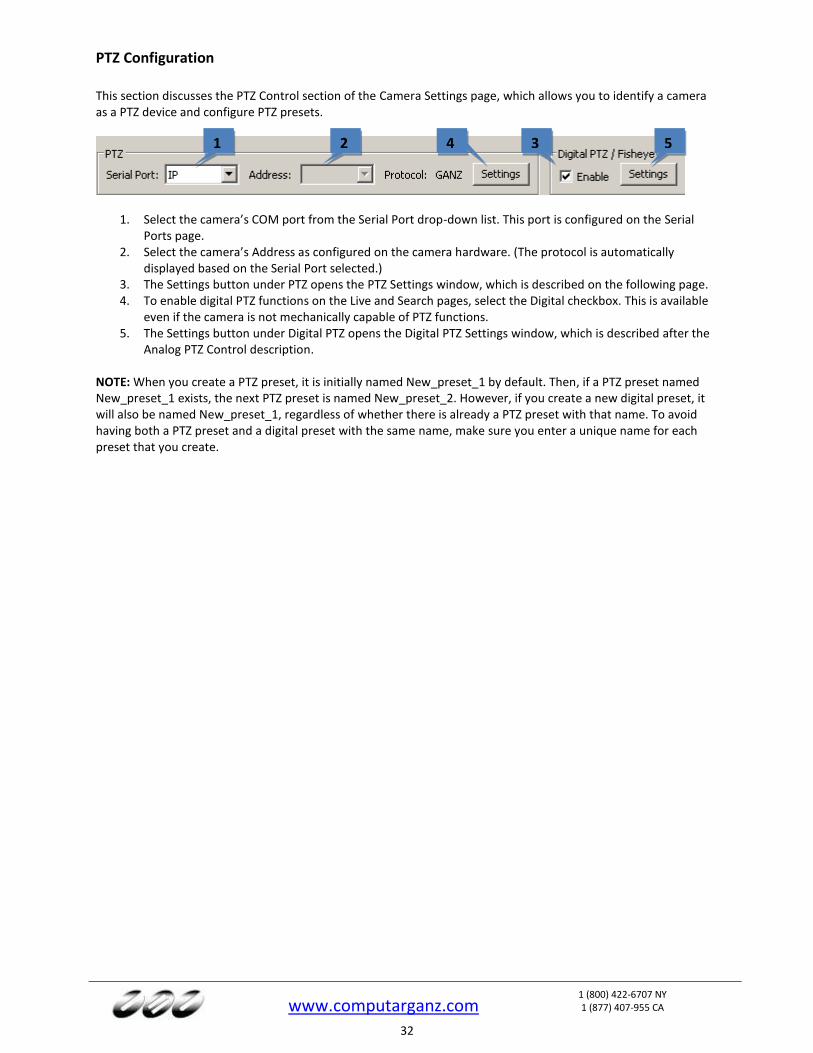
PTZ Configuration
This section discusses the PTZ Control section of the Camera Settings page, which allows you to identify a camera as a PTZ device and configure PTZ presets.
1. Select the camera’s COM port from the Serial Port drop-down list. This port is configured on the Serial Ports page.
2. Select the camera’s Address as configured on the camera hardware. (The protocol is automatically displayed based on the Serial Port selected.)
3. The Settings button under PTZ opens the PTZ Settings window, which is described on the following page. 4. To enable digital PTZ functions on the Live and Search pages, select the Digital checkbox. This is available
even if the camera is not mechanically capable of PTZ functions. 5. The Settings button under Digital PTZ opens the Digital PTZ Settings window, which is described after the
Analog PTZ Control description. NOTE: When you create a PTZ preset, it is initially named New_preset_1 by default. Then, if a PTZ preset named New_preset_1 exists, the next PTZ preset is named New_preset_2. However, if you create a new digital preset, it will also be named New_preset_1, regardless of whether there is already a PTZ preset with that name. To avoid having both a PTZ preset and a digital preset with the same name, make sure you enter a unique name for each preset that you create.
1 2 3 4 5
www.computarganz.com
1 (800) 422-6707 NY 1 (877) 407-955 CA
33
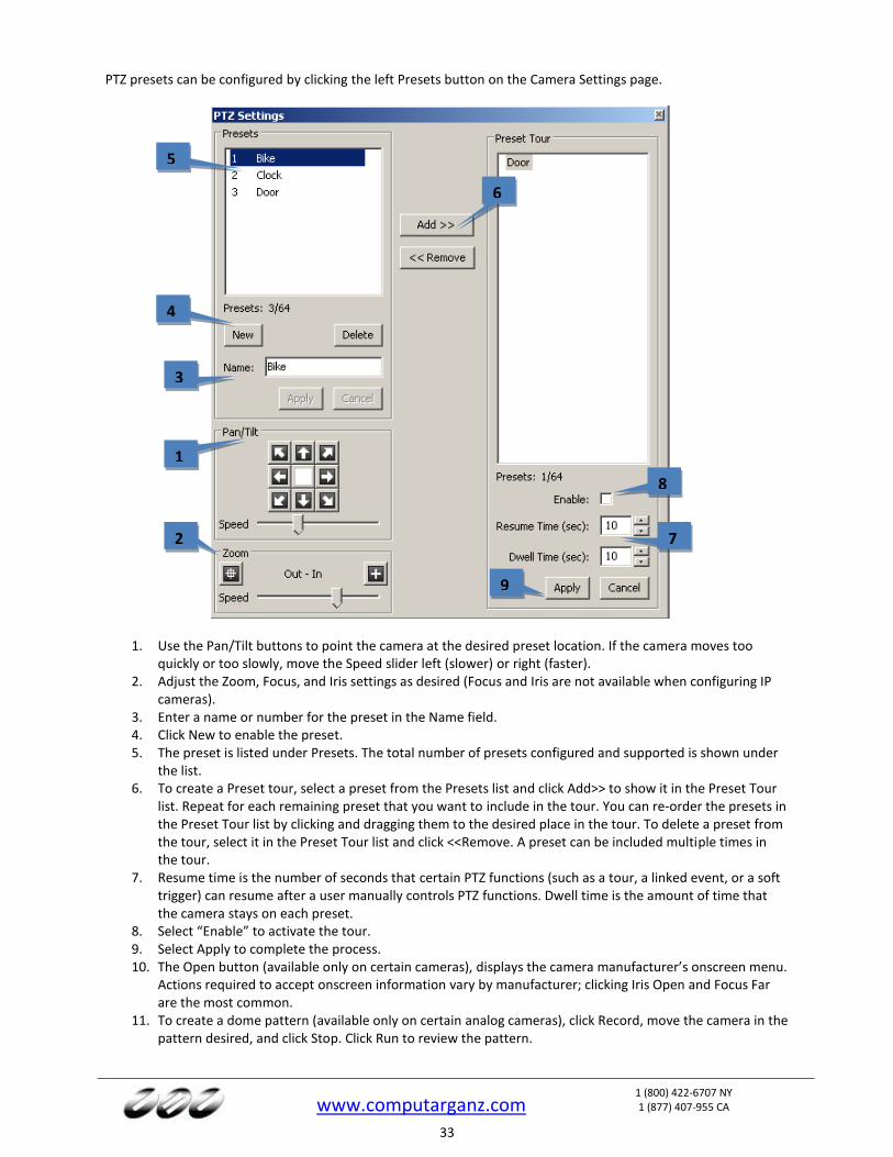
PTZ presets can be configured by clicking the left Presets button on the Camera Settings page.
1. Use the Pan/Tilt buttons to point the camera at the desired preset location. If the camera moves too quickly or too slowly, move the Speed slider left (slower) or right (faster).
2. Adjust the Zoom, Focus, and Iris settings as desired (Focus and Iris are not available when configuring IP cameras).
3. Enter a name or number for the preset in the Name field. 4. Click New to enable the preset. 5. The preset is listed under Presets. The total number of presets configured and supported is shown under
the list. 6. To create a Preset tour, select a preset from the Presets list and click Add>> to show it in the Preset Tour
list. Repeat for each remaining preset that you want to include in the tour. You can re-order the presets in the Preset Tour list by clicking and dragging them to the desired place in the tour. To delete a preset from the tour, select it in the Preset Tour list and click <<Remove. A preset can be included multiple times in the tour.
7. Resume time is the number of seconds that certain PTZ functions (such as a tour, a linked event, or a soft trigger) can resume after a user manually controls PTZ functions. Dwell time is the amount of time that the camera stays on each preset.
8. Select “Enable” to activate the tour. 9. Select Apply to complete the process. 10. The Open button (available only on certain cameras), displays the camera manufacturer’s onscreen menu.
Actions required to accept onscreen information vary by manufacturer; clicking Iris Open and Focus Far are the most common.
11. To create a dome pattern (available only on certain analog cameras), click Record, move the camera in the pattern desired, and click Stop. Click Run to review the pattern.
1
3
2
4
5
6
7
8
9
www.computarganz.com
1 (800) 422-6707 NY 1 (877) 407-955 CA
34
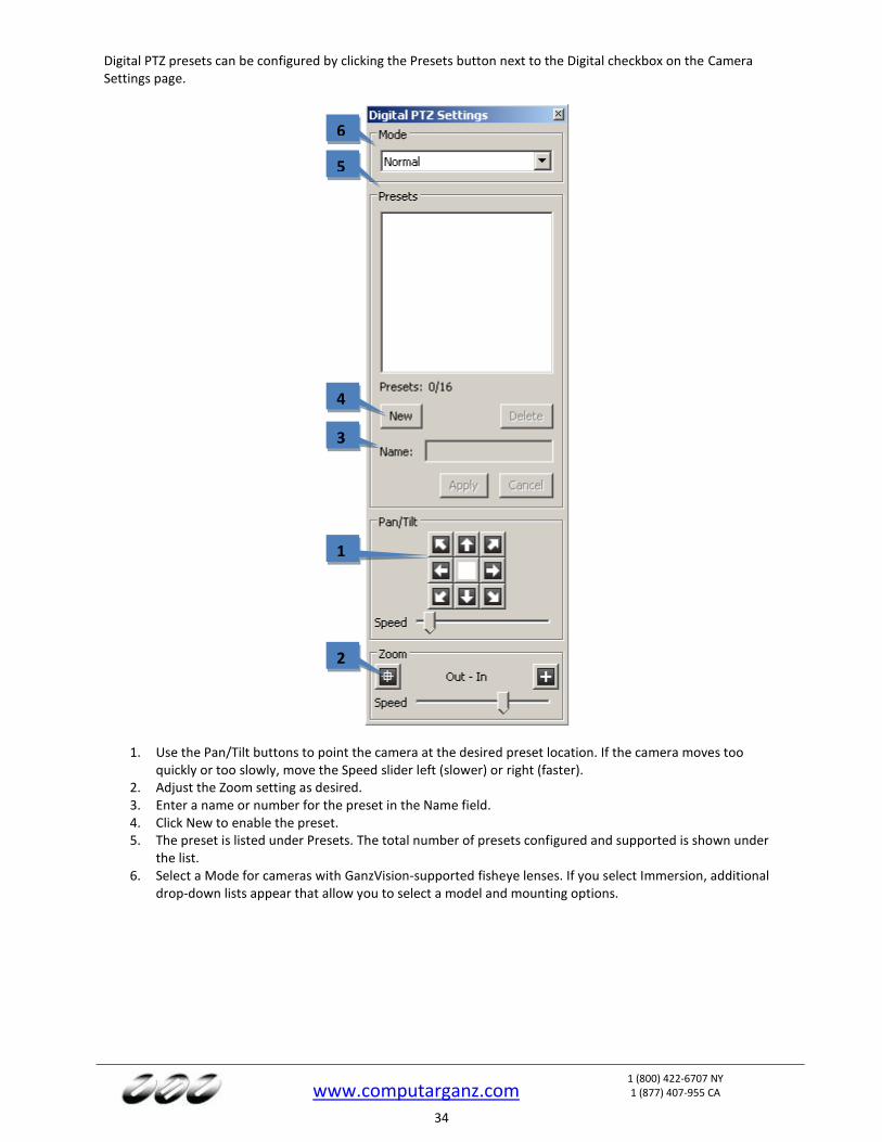
Digital PTZ presets can be configured by clicking the Presets button next to the Digital checkbox on the Camera Settings page.
1. Use the Pan/Tilt buttons to point the camera at the desired preset location. If the camera moves too quickly or too slowly, move the Speed slider left (slower) or right (faster).
2. Adjust the Zoom setting as desired. 3. Enter a name or number for the preset in the Name field. 4. Click New to enable the preset. 5. The preset is listed under Presets. The total number of presets configured and supported is shown under
the list. 6. Select a Mode for cameras with GanzVision-supported fisheye lenses. If you select Immersion, additional
drop-down lists appear that allow you to select a model and mounting options.
1
3
2
4
5
6
www.computarganz.com
1 (800) 422-6707 NY 1 (877) 407-955 CA
35
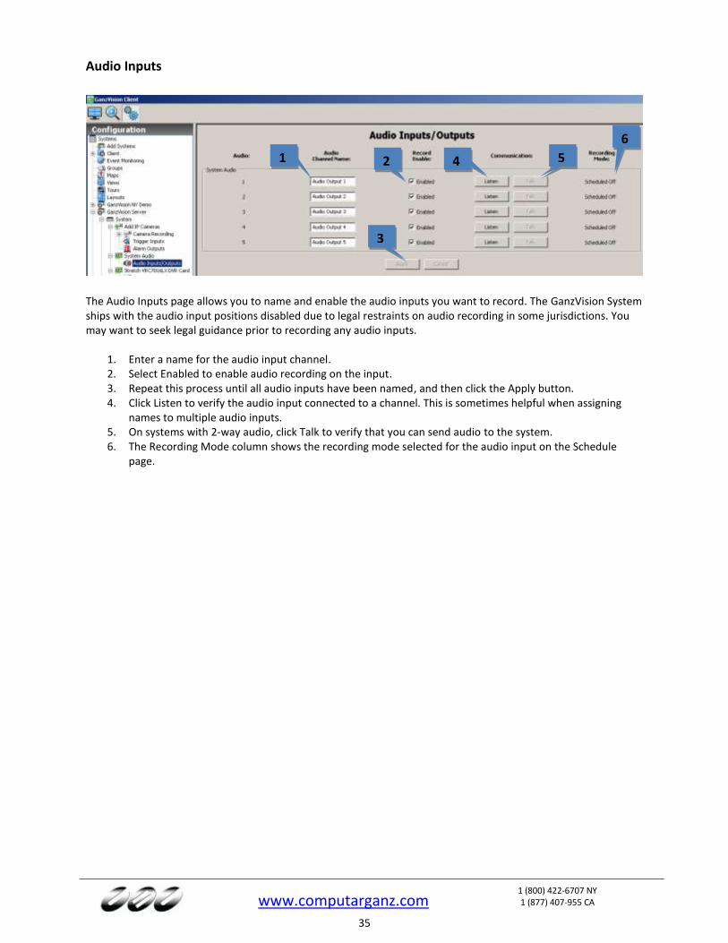
Audio Inputs
The Audio Inputs page allows you to name and enable the audio inputs you want to record. The GanzVision System ships with the audio input positions disabled due to legal restraints on audio recording in some jurisdictions. You may want to seek legal guidance prior to recording any audio inputs.
1. Enter a name for the audio input channel. 2. Select Enabled to enable audio recording on the input. 3. Repeat this process until all audio inputs have been named, and then click the Apply button. 4. Click Listen to verify the audio input connected to a channel. This is sometimes helpful when assigning
names to multiple audio inputs. 5. On systems with 2-way audio, click Talk to verify that you can send audio to the system. 6. The Recording Mode column shows the recording mode selected for the audio input on the Schedule
page.
1 2
3
4
6
5
www.computarganz.com
1 (800) 422-6707 NY 1 (877) 407-955 CA
36
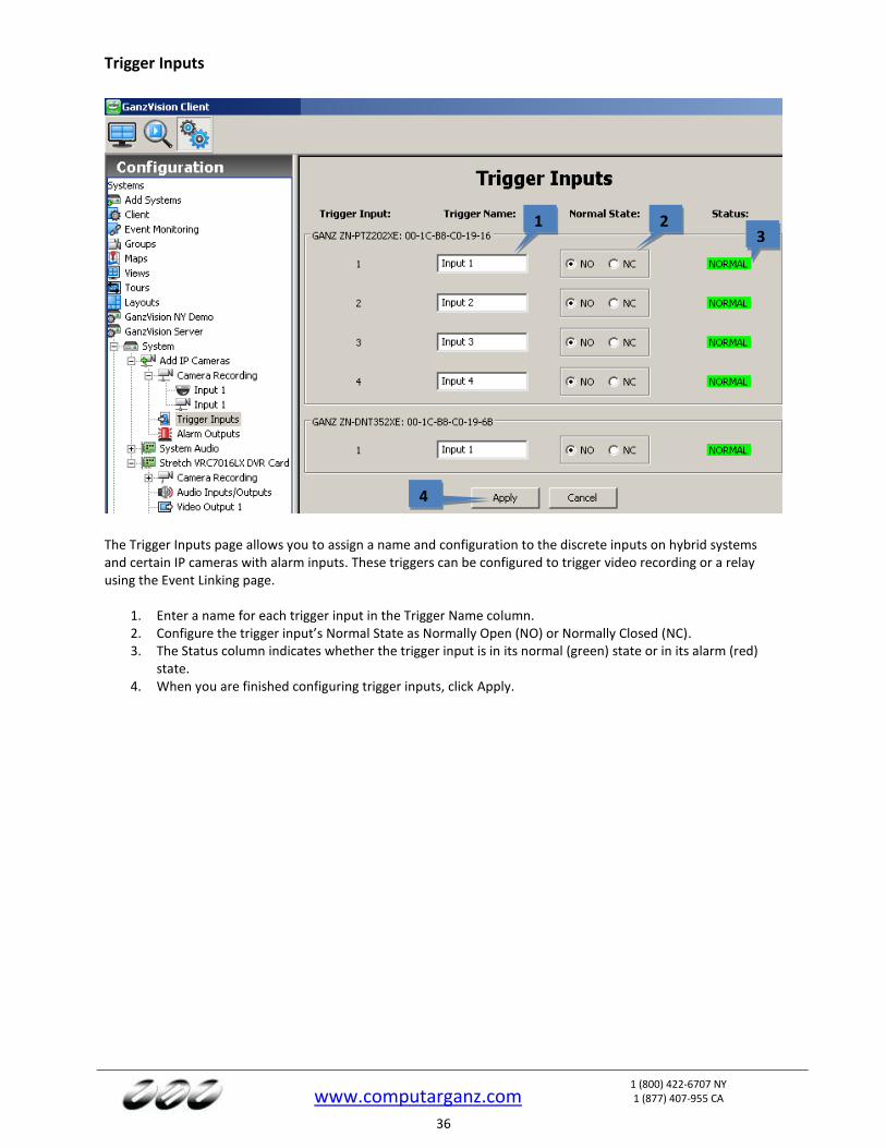
Trigger Inputs
The Trigger Inputs page allows you to assign a name and configuration to the discrete inputs on hybrid systems and certain IP cameras with alarm inputs. These triggers can be configured to trigger video recording or a relay using the Event Linking page.
1. Enter a name for each trigger input in the Trigger Name column. 2. Configure the trigger input’s Normal State as Normally Open (NO) or Normally Closed (NC). 3. The Status column indicates whether the trigger input is in its normal (green) state or in its alarm (red)
state. 4. When you are finished configuring trigger inputs, click Apply.
1 2 3
4
www.computarganz.com
1 (800) 422-6707 NY 1 (877) 407-955 CA
37
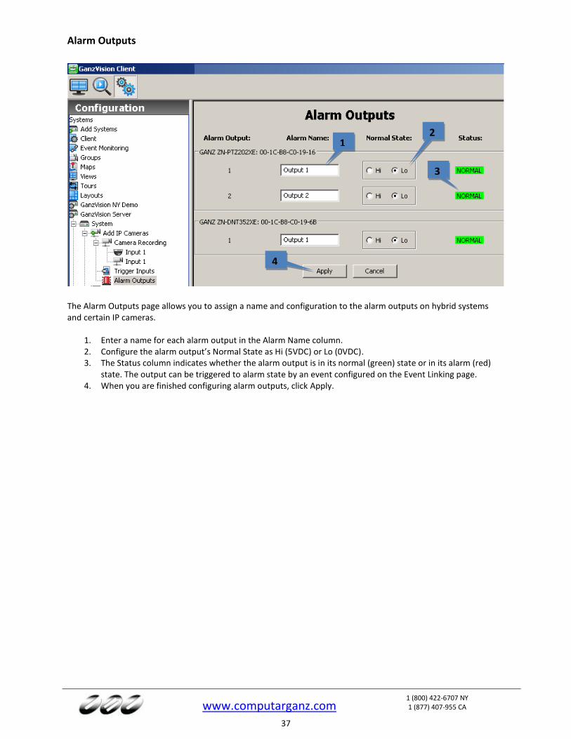
Alarm Outputs
The Alarm Outputs page allows you to assign a name and configuration to the alarm outputs on hybrid systems and certain IP cameras.
1. Enter a name for each alarm output in the Alarm Name column. 2. Configure the alarm output’s Normal State as Hi (5VDC) or Lo (0VDC). 3. The Status column indicates whether the alarm output is in its normal (green) state or in its alarm (red)
state. The output can be triggered to alarm state by an event configured on the Event Linking page. 4. When you are finished configuring alarm outputs, click Apply.
1 2
3
4
www.computarganz.com
1 (800) 422-6707 NY 1 (877) 407-955 CA
38
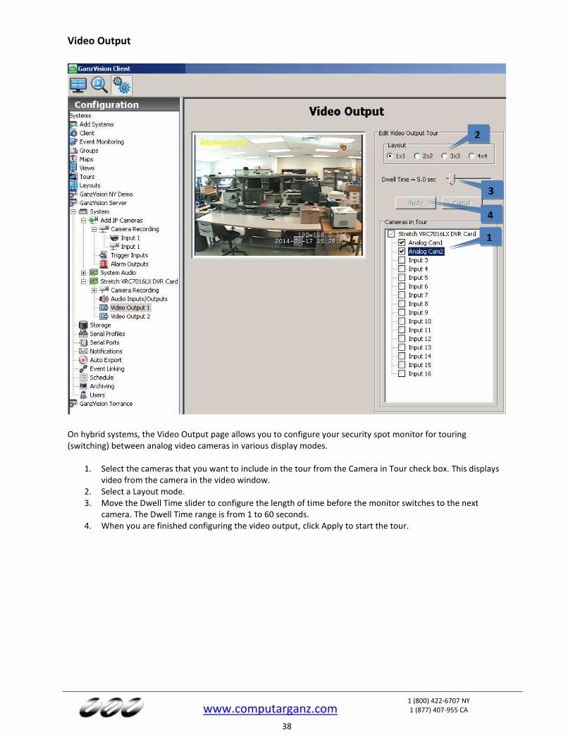
Video Output
On hybrid systems, the Video Output page allows you to configure your security spot monitor for touring (switching) between analog video cameras in various display modes.
1. Select the cameras that you want to include in the tour from the Camera in Tour check box. This displays video from the camera in the video window.
2. Select a Layout mode. 3. Move the Dwell Time slider to configure the length of time before the monitor switches to the next
camera. The Dwell Time range is from 1 to 60 seconds. 4. When you are finished configuring the video output, click Apply to start the tour.
1
2
3
4
www.computarganz.com
1 (800) 422-6707 NY 1 (877) 407-955 CA
39
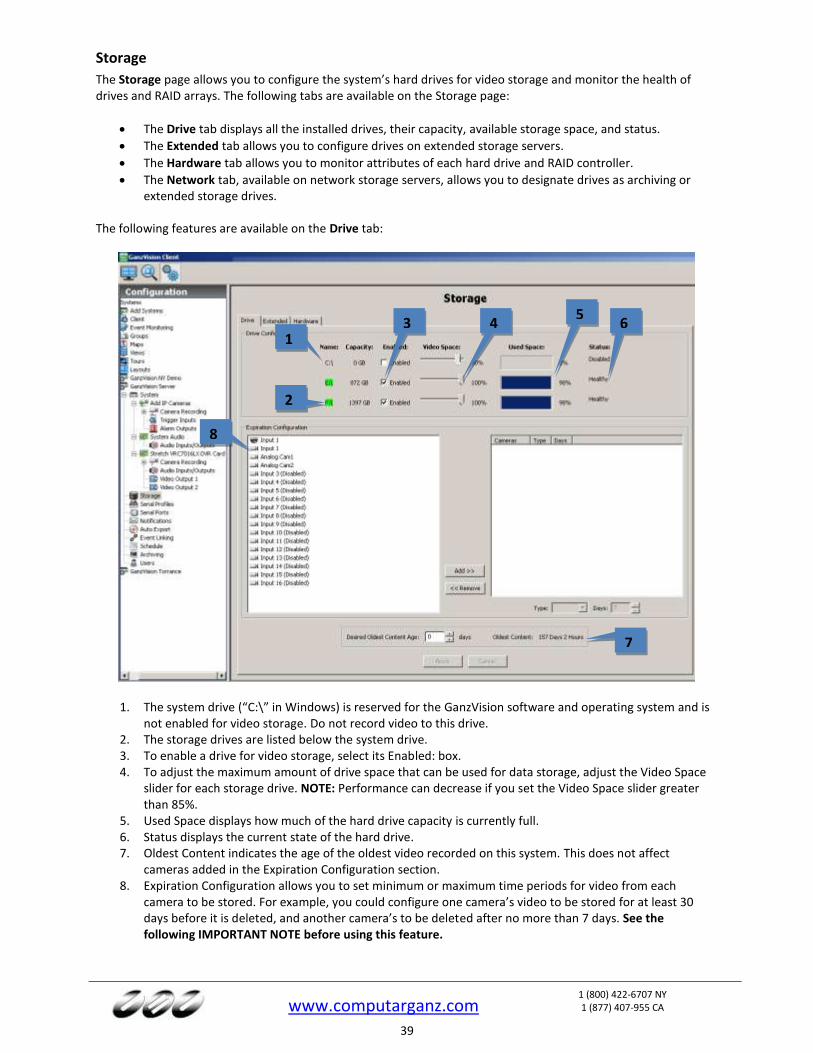
Storage
The Storage page allows you to configure the system’s hard drives for video storage and monitor the health of drives and RAID arrays. The following tabs are available on the Storage page:
The Drive tab displays all the installed drives, their capacity, available storage space, and status.
The Extended tab allows you to configure drives on extended storage servers.
The Hardware tab allows you to monitor attributes of each hard drive and RAID controller.
The Network tab, available on network storage servers, allows you to designate drives as archiving or extended storage drives.
The following features are available on the Drive tab:
1. The system drive (“C:\” in Windows) is reserved for the GanzVision software and operating system and is not enabled for video storage. Do not record video to this drive.
2. The storage drives are listed below the system drive. 3. To enable a drive for video storage, select its Enabled: box. 4. To adjust the maximum amount of drive space that can be used for data storage, adjust the Video Space
slider for each storage drive. NOTE: Performance can decrease if you set the Video Space slider greater than 85%.
5. Used Space displays how much of the hard drive capacity is currently full. 6. Status displays the current state of the hard drive. 7. Oldest Content indicates the age of the oldest video recorded on this system. This does not affect
cameras added in the Expiration Configuration section. 8. Expiration Configuration allows you to set minimum or maximum time periods for video from each
camera to be stored. For example, you could configure one camera’s video to be stored for at least 30 days before it is deleted, and another camera’s to be deleted after no more than 7 days. See the following IMPORTANT NOTE before using this feature.
1
2
3 5
65
7
4
8
www.computarganz.com
1 (800) 422-6707 NY 1 (877) 407-955 CA
40
IMPORTANT NOTE
The system normally retains recorded video from all cameras for as long as possible, deleting the oldest video only when required to create room for newly recorded video. Thus, it is recommended that you use the Expiration Configuration feature only when necessary, such as when video must be deleted after a specific maximum time period as required by law. When using the feature, the Days of Recorded Video indicator should be higher than the greatest number of minimum days configured for a camera in the Expiration Configuration area. For example, if you configure a camera’s video to be stored for at least 30 days, the Days of Recorded Video indicator should be at least 30 (assuming the system has been recording video for at least 30 days). If the Days of Recorded Video indicator were lower than 30, video recording would stop for that camera until the oldest video stored from that camera got deleted (after 30 days). To resolve issues with video expiration, you can expand your storage capacity by adding hard drives, reducing the minimum time that video needs to be stored, or reducing frame rates or quality settings for the applicable cameras. The best way to determine your needs is by trial and error; allow the system to record at your desired settings and then monitor the Storage page to ensure that the settings will meet the storage requirements.
To configure video expiration, select a camera name in the list on the left and click Add>>. (You can select multiple cameras by pressing the Ctrl or Shift buttons.) Then select the camera name in the list on the right. You can configure two types of expiration:
To delete video after a certain amount of time, select At Most from the Type drop-down list and use the arrows to select the maximum number of days the video should be stored.
NOTE: If an At Most setting is configured for a camera, the camera cannot be selected for archiving.
To save video for a minimum amount of time, select At Least from the Type drop-down list and use the arrows to select the minimum number of days the video should be stored.
Repeat for each camera that requires expiration rules. To remove expiration rules, select one or more camera names in the list on the right and click <<Remove. Click Apply when finished.
www.computarganz.com
1 (800) 422-6707 NY 1 (877) 407-955 CA
41
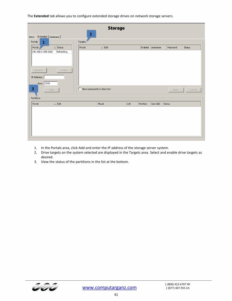
The Extended tab allows you to configure extended storage drives on network storage servers.
1. In the Portals area, click Add and enter the IP address of the storage server system. 2. Drive targets on the system selected are displayed in the Targets area. Select and enable drive targets as
desired. 3. View the status of the partitions in the list at the bottom.
1
2
3
www.computarganz.com
1 (800) 422-6707 NY 1 (877) 407-955 CA
42
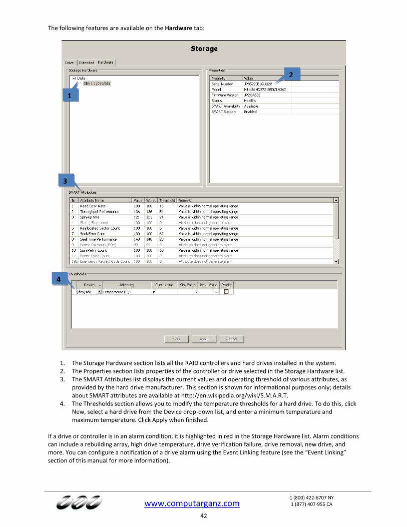
The following features are available on the Hardware tab:
1. The Storage Hardware section lists all the RAID controllers and hard drives installed in the system. 2. The Properties section lists properties of the controller or drive selected in the Storage Hardware list. 3. The SMART Attributes list displays the current values and operating threshold of various attributes, as
provided by the hard drive manufacturer. This section is shown for informational purposes only; details about SMART attributes are available at http://en.wikipedia.org/wiki/S.M.A.R.T.
4. The Thresholds section allows you to modify the temperature thresholds for a hard drive. To do this, click New, select a hard drive from the Device drop-down list, and enter a minimum temperature and maximum temperature. Click Apply when finished.
If a drive or controller is in an alarm condition, it is highlighted in red in the Storage Hardware list. Alarm conditions can include a rebuilding array, high drive temperature, drive verification failure, drive removal, new drive, and more. You can configure a notification of a drive alarm using the Event Linking feature (see the “Event Linking” section of this manual for more information).
1
2
3
4
www.computarganz.com
1 (800) 422-6707 NY 1 (877) 407-955 CA
43
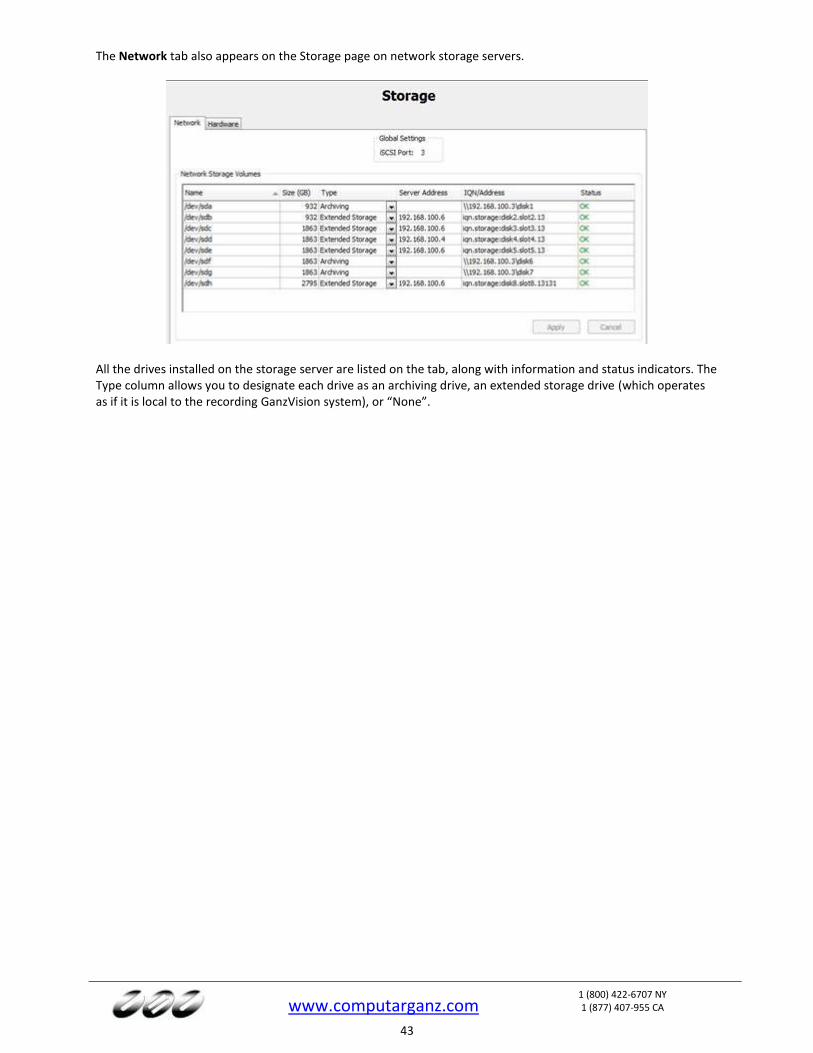
The Network tab also appears on the Storage page on network storage servers.
All the drives installed on the storage server are listed on the tab, along with information and status indicators. The Type column allows you to designate each drive as an archiving drive, an extended storage drive (which operates as if it is local to the recording GanzVision system), or “None”.
www.computarganz.com
1 (800) 422-6707 NY 1 (877) 407-955 CA
44
Notifications
NOTE: The Notifications page is not available in GanzVision Start. The Notifications page allows you to configure an e-mail server and message profile that will send an email message when an event occurs. To configure events that cause an email notification to be sent using these email settings, see the “Event Linking” section of this manual. The Notifications page is separated into three tabs: E-mail Message Profiles, E-mail Servers, and Web Server.
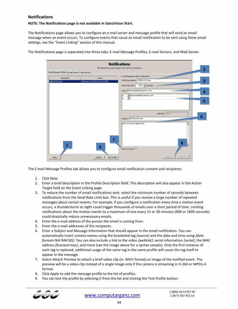
The E-mail Message Profiles tab allows you to configure email notification content and recipients.
1. Click New. 2. Enter a brief description in the Profile Description field. This description will also appear in the Action
Target field on the Event Linking page. 3. To reduce the number of email notifications sent, select the minimum number of seconds between
notifications from the Send Rate Limit box. This is useful if you receive a large number of repeated messages about certain events. For example, if you configure a notification every time a motion event occurs, a thunderstorm at night could trigger thousands of emails over a short period of time. Limiting notifications about the motion events to a maximum of one every 15 or 30 minutes (900 or 1800 seconds) could drastically reduce unnecessary emails.
4. Enter the e-mail address of the person the email is coming from. 5. Enter the e-mail addresses of the recipients. 6. Enter a Subject and Message information that should appear in the email notification. You can
automatically insert camera names using the bracketed tag {source} and the date and time using {date format=%H:%M:%S}. You can also include a link to the video {weblink}, serial information {serial}, the MAC address {licensed mac}, and more (see the image above for a syntax sample). Only the first instance of each tag is replaced; additional usage of the same tag in the same profile will cause the tag itself to appear in the message.
7. Select Attach Preview to attach a brief video clip (in .MOV format) or image of the notified event. The preview will be a video clip instead of a single image only if the camera is streaming in H.264 or MPEG-4 format.
8. Click Apply to add the message profile to the list of profiles. 9. You can test the profile by selecting it from the list and clicking the Test Profile button.
1
2
3
4
5
6
8 7
9
www.computarganz.com
1 (800) 422-6707 NY 1 (877) 407-955 CA
45
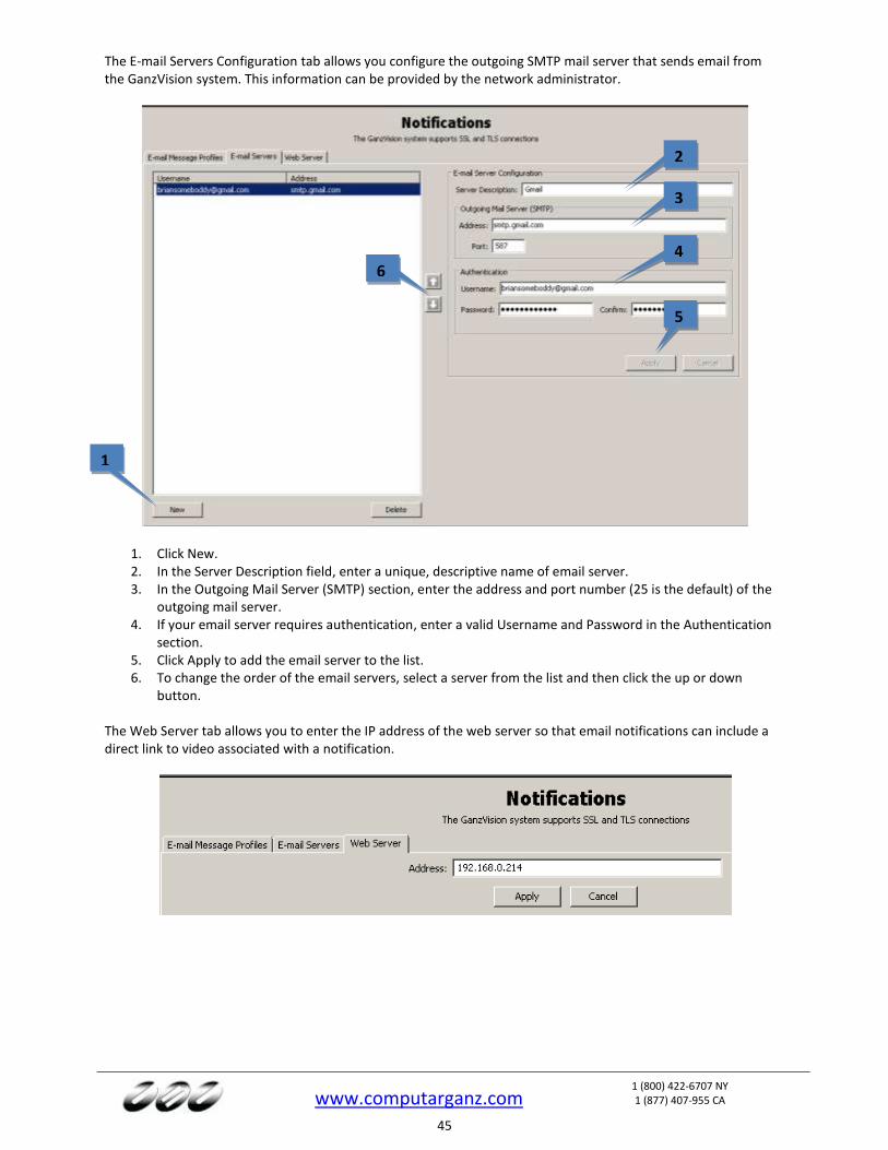
The E-mail Servers Configuration tab allows you configure the outgoing SMTP mail server that sends email from the GanzVision system. This information can be provided by the network administrator.
1. Click New. 2. In the Server Description field, enter a unique, descriptive name of email server. 3. In the Outgoing Mail Server (SMTP) section, enter the address and port number (25 is the default) of the
outgoing mail server. 4. If your email server requires authentication, enter a valid Username and Password in the Authentication
section. 5. Click Apply to add the email server to the list. 6. To change the order of the email servers, select a server from the list and then click the up or down
button. The Web Server tab allows you to enter the IP address of the web server so that email notifications can include a direct link to video associated with a notification.
1
2
3
4
5
6

www.computarganz.com
1 (800) 422-6707 NY 1 (877) 407-955 CA
46
A GanzVision server can also send automated text messages. To configure a text message notification, complete the following steps:
1. Create a list of all phone numbers and their service providers that will be notified. For ported phones, you must know the current service provider, not the previous service provider.
2. Look up the service provider’s e-mail-to-text service gateway address at a public web site. 3. Test your existing e-mail server connection by configuring an e-mail server, creating a notification profile
to your e-mail address, and configuring an event link to send a notification upon event. 4. After confirming the existing e-mail server is operational, add a new profile on the Notification page to
send text messages. 5. Enter one or more text recipients in the e-mail message profile, with a format of
PhoneNumber@SMSProvider, such as [email protected] and [email protected] (which would send a text to AT&T and Verizon recipients, respectively).
6. Enter a Subject and a message of 140 characters or less. (Some providers will not display the Subject line in the received text message, but you must enter at least one character for the Subject anyway.)
7. On the Event Linking page, configure one or more events to use the new text profile. 8. If necessary, create multiple notification profiles for multiple user groups or events.
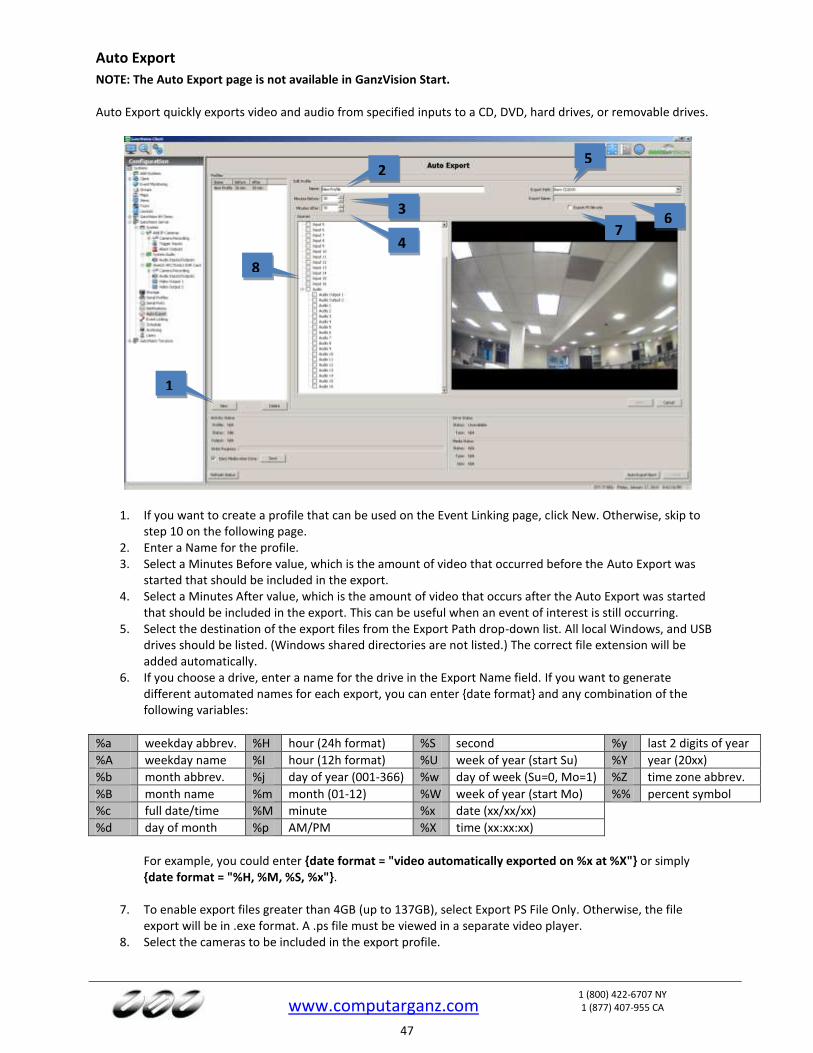
www.computarganz.com
1 (800) 422-6707 NY 1 (877) 407-955 CA
47
Auto Export
NOTE: The Auto Export page is not available in GanzVision Start. Auto Export quickly exports video and audio from specified inputs to a CD, DVD, hard drives, or removable drives.
1. If you want to create a profile that can be used on the Event Linking page, click New. Otherwise, skip to step 10 on the following page.
2. Enter a Name for the profile. 3. Select a Minutes Before value, which is the amount of video that occurred before the Auto Export was
started that should be included in the export. 4. Select a Minutes After value, which is the amount of video that occurs after the Auto Export was started
that should be included in the export. This can be useful when an event of interest is still occurring. 5. Select the destination of the export files from the Export Path drop-down list. All local Windows, and USB
drives should be listed. (Windows shared directories are not listed.) The correct file extension will be added automatically.
6. If you choose a drive, enter a name for the drive in the Export Name field. If you want to generate different automated names for each export, you can enter {date format} and any combination of the following variables:
%a weekday abbrev. %H hour (24h format) %S second %y last 2 digits of year
%A weekday name %I hour (12h format) %U week of year (start Su) %Y year (20xx)
%b month abbrev. %j day of year (001-366) %w day of week (Su=0, Mo=1) %Z time zone abbrev.
%B month name %m month (01-12) %W week of year (start Mo) %% percent symbol
%c full date/time %M minute %x date (xx/xx/xx)
%d day of month %p AM/PM %X time (xx:xx:xx)
For example, you could enter {date format = "video automatically exported on %x at %X"} or simply
{date format = "%H, %M, %S, %x"}.
7. To enable export files greater than 4GB (up to 137GB), select Export PS File Only. Otherwise, the file export will be in .exe format. A .ps file must be viewed in a separate video player.
8. Select the cameras to be included in the export profile.
2
1
3
4
8
5
7 6
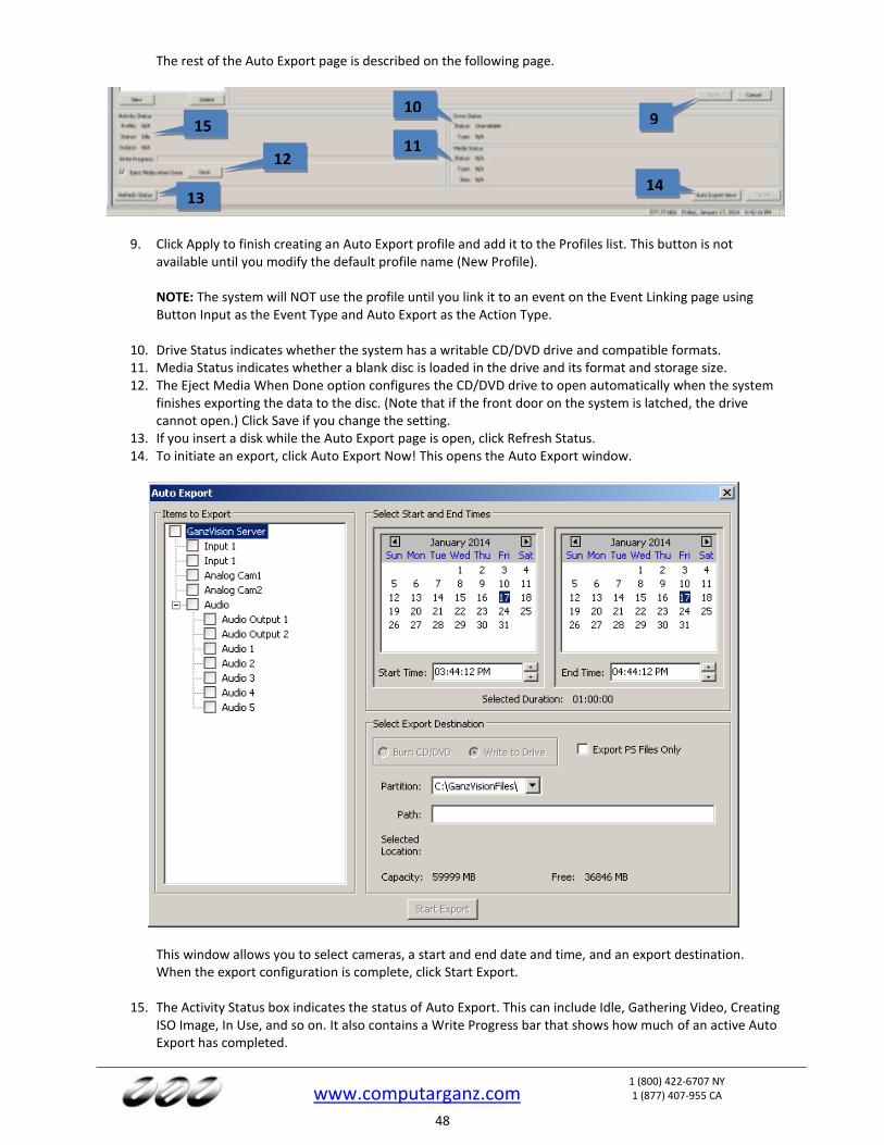
www.computarganz.com
1 (800) 422-6707 NY 1 (877) 407-955 CA
48
The rest of the Auto Export page is described on the following page.
9. Click Apply to finish creating an Auto Export profile and add it to the Profiles list. This button is not available until you modify the default profile name (New Profile). NOTE: The system will NOT use the profile until you link it to an event on the Event Linking page using Button Input as the Event Type and Auto Export as the Action Type.
10. Drive Status indicates whether the system has a writable CD/DVD drive and compatible formats. 11. Media Status indicates whether a blank disc is loaded in the drive and its format and storage size. 12. The Eject Media When Done option configures the CD/DVD drive to open automatically when the system
finishes exporting the data to the disc. (Note that if the front door on the system is latched, the drive cannot open.) Click Save if you change the setting.
13. If you insert a disk while the Auto Export page is open, click Refresh Status. 14. To initiate an export, click Auto Export Now! This opens the Auto Export window.
This window allows you to select cameras, a start and end date and time, and an export destination. When the export configuration is complete, click Start Export.
15. The Activity Status box indicates the status of Auto Export. This can include Idle, Gathering Video, Creating ISO Image, In Use, and so on. It also contains a Write Progress bar that shows how much of an active Auto Export has completed.
12
15
11
14 13
9 10
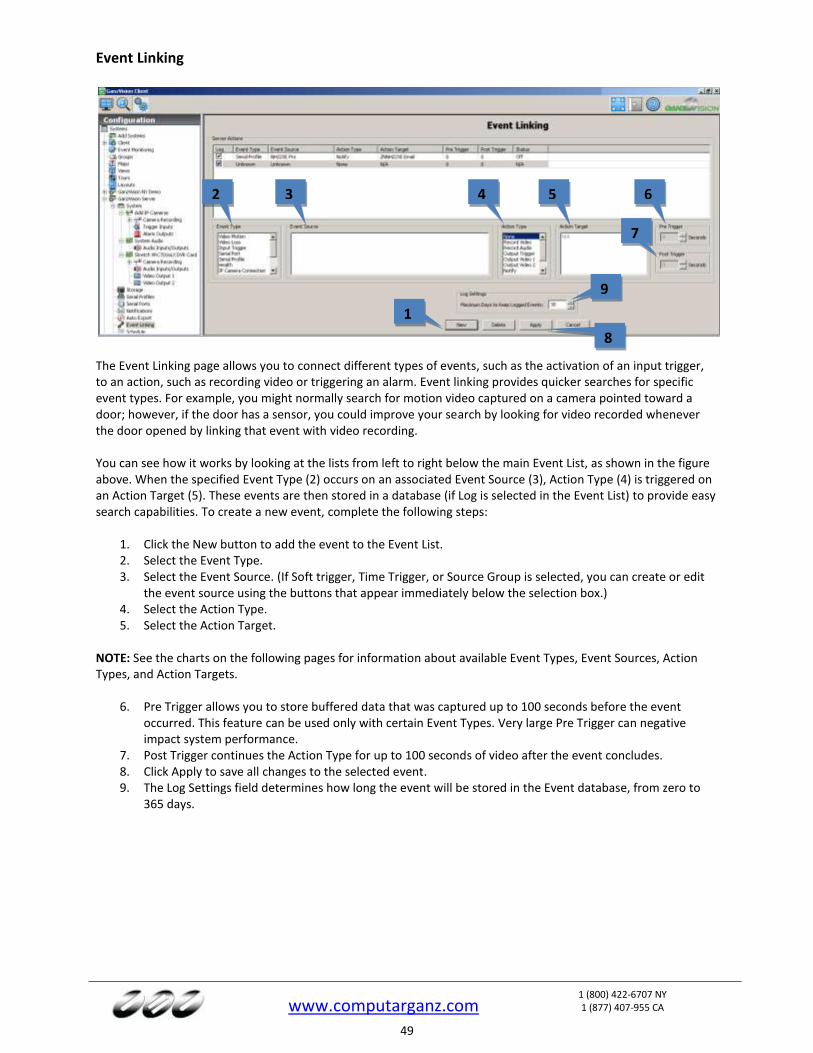
www.computarganz.com
1 (800) 422-6707 NY 1 (877) 407-955 CA
49
Event Linking
The Event Linking page allows you to connect different types of events, such as the activation of an input trigger, to an action, such as recording video or triggering an alarm. Event linking provides quicker searches for specific event types. For example, you might normally search for motion video captured on a camera pointed toward a door; however, if the door has a sensor, you could improve your search by looking for video recorded whenever the door opened by linking that event with video recording. You can see how it works by looking at the lists from left to right below the main Event List, as shown in the figure above. When the specified Event Type (2) occurs on an associated Event Source (3), Action Type (4) is triggered on an Action Target (5). These events are then stored in a database (if Log is selected in the Event List) to provide easy search capabilities. To create a new event, complete the following steps:
1. Click the New button to add the event to the Event List. 2. Select the Event Type. 3. Select the Event Source. (If Soft trigger, Time Trigger, or Source Group is selected, you can create or edit
the event source using the buttons that appear immediately below the selection box.) 4. Select the Action Type. 5. Select the Action Target.
NOTE: See the charts on the following pages for information about available Event Types, Event Sources, Action Types, and Action Targets.
6. Pre Trigger allows you to store buffered data that was captured up to 100 seconds before the event
occurred. This feature can be used only with certain Event Types. Very large Pre Trigger can negative impact system performance.
7. Post Trigger continues the Action Type for up to 100 seconds of video after the event concludes. 8. Click Apply to save all changes to the selected event. 9. The Log Settings field determines how long the event will be stored in the Event database, from zero to
365 days.
1
2 3 4 5 6
7
8
9
www.computarganz.com
1 (800) 422-6707 NY 1 (877) 407-955 CA
50
The following Event Types are available: NOTE: Input Trigger is the only Event Type available on GanzVision Start systems.
Event Type Description
Video Motion Camera detects motion.
Video Loss Analog video signal is disconnected.
Input Trigger Discrete input on hybrid server or IP camera with alarm input is activated.
Serial Port Key word entered on Serial Profile page is detected on a pre-selected port.
Serial Profile Key word is detected on any Serial Port with that profile.
Health Detected problem involving the health of the GanzVision server hardware.
IP Camera Connection Network can’t connect to the IP Camera.
Soft Trigger Signal sent from the client to the server.
Time Trigger Time of day or day of week reached.
Analytics Video analytics event detected.
Source Group Multiple event types for advanced event linking.
The Event Source list varies depending on the Event Type selected:
Event Type Selected Event Source
Video Motion Any of the cameras connected to the GanzVision server.
Video Loss Any analog camera connected to the GanzVision server.
Input Trigger Any input trigger on the back of the server or IP camera connected to the server. The system defaults to a device and input number, but these can be customized on the Trigger Input page. See the “Trigger Inputs” section of this manual for details.
Serial Port Any of the serial ports configured on the server. See the “Serial Ports” section of this manual for details.
Serial Profile Any of the serial profiles you have configured. You can select all key words associated with a serial profile by selecting the profile name, or you can select an individual key word configured in the profile.
Health Includes failures or temperature problems on a device; problems with storage configuration; subscription expiration; video throttling alarms; alarms related to parameters monitored on the Hardware Monitoring tab on the System page; failed connection to shared network drive for archiving.
IP Camera Connection Any of the IP cameras connected to the GanzVision server.
Soft Trigger Select New to create a new soft trigger with a default name. Double-click to name it, or click Delete to remove it. You can also select any of the pre-configured soft triggers that are listed.
Time Trigger Select New to open a window. Name the time trigger, select a start and end time, and select the days of the week when the selected action should occur. (For example, you could perform an Auto Export at 2:00 every morning.)
Analytics A list of video analytics events (configured through the provider’s interface).
Source Group Select New to open a window. You can then select any combination of event types and event sources and determine whether any or all of them must occur to trigger the selected action.
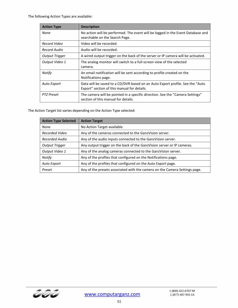
www.computarganz.com
1 (800) 422-6707 NY 1 (877) 407-955 CA
51
The following Action Types are available:
Action Type Description
None No action will be performed. The event will be logged in the Event Database and searchable on the Search Page.
Record Video Video will be recorded.
Record Audio Audio will be recorded.
Output Trigger A wired output trigger on the back of the server or IP camera will be activated.
Output Video 1 The analog monitor will switch to a full-screen view of the selected camera.
Notify An email notification will be sent according to profile created on the Notifications page.
Auto Export Data will be saved to a CD/DVR based on an Auto Export profile. See the “Auto Export” section of this manual for details.
PTZ Preset The camera will be pointed in a specific direction. See the “Camera Settings” section of this manual for details.
The Action Target list varies depending on the Action Type selected:
Action Type Selected Action Target
None No Action Target available.
Recorded Video Any of the cameras connected to the GanzVision server.
Recorded Audio Any of the audio inputs connected to the GanzVision server.
Output Trigger Any output trigger on the back of the GanzVision server or IP cameras.
Output Video 1 Any of the analog cameras connected to the GanzVision server.
Notify Any of the profiles that configured on the Notifications page.
Auto Export Any of the profiles that configured on the Auto Export page.
Preset Any of the presets associated with the camera on the Camera Settings page.
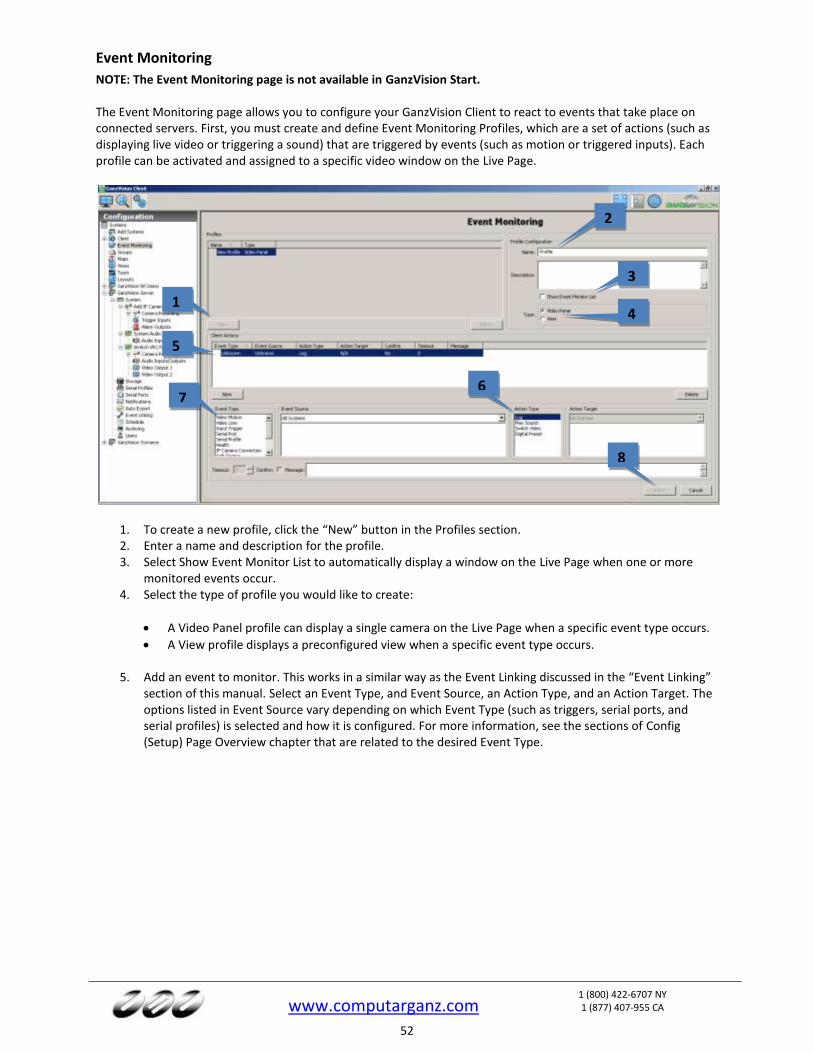
www.computarganz.com
1 (800) 422-6707 NY 1 (877) 407-955 CA
52
Event Monitoring
NOTE: The Event Monitoring page is not available in GanzVision Start. The Event Monitoring page allows you to configure your GanzVision Client to react to events that take place on connected servers. First, you must create and define Event Monitoring Profiles, which are a set of actions (such as displaying live video or triggering a sound) that are triggered by events (such as motion or triggered inputs). Each profile can be activated and assigned to a specific video window on the Live Page.
1. To create a new profile, click the “New” button in the Profiles section. 2. Enter a name and description for the profile. 3. Select Show Event Monitor List to automatically display a window on the Live Page when one or more
monitored events occur. 4. Select the type of profile you would like to create:
A Video Panel profile can display a single camera on the Live Page when a specific event type occurs.
A View profile displays a preconfigured view when a specific event type occurs.
5. Add an event to monitor. This works in a similar way as the Event Linking discussed in the “Event Linking” section of this manual. Select an Event Type, and Event Source, an Action Type, and an Action Target. The options listed in Event Source vary depending on which Event Type (such as triggers, serial ports, and serial profiles) is selected and how it is configured. For more information, see the sections of Config (Setup) Page Overview chapter that are related to the desired Event Type.
1
2
3
4
8
6
5
7
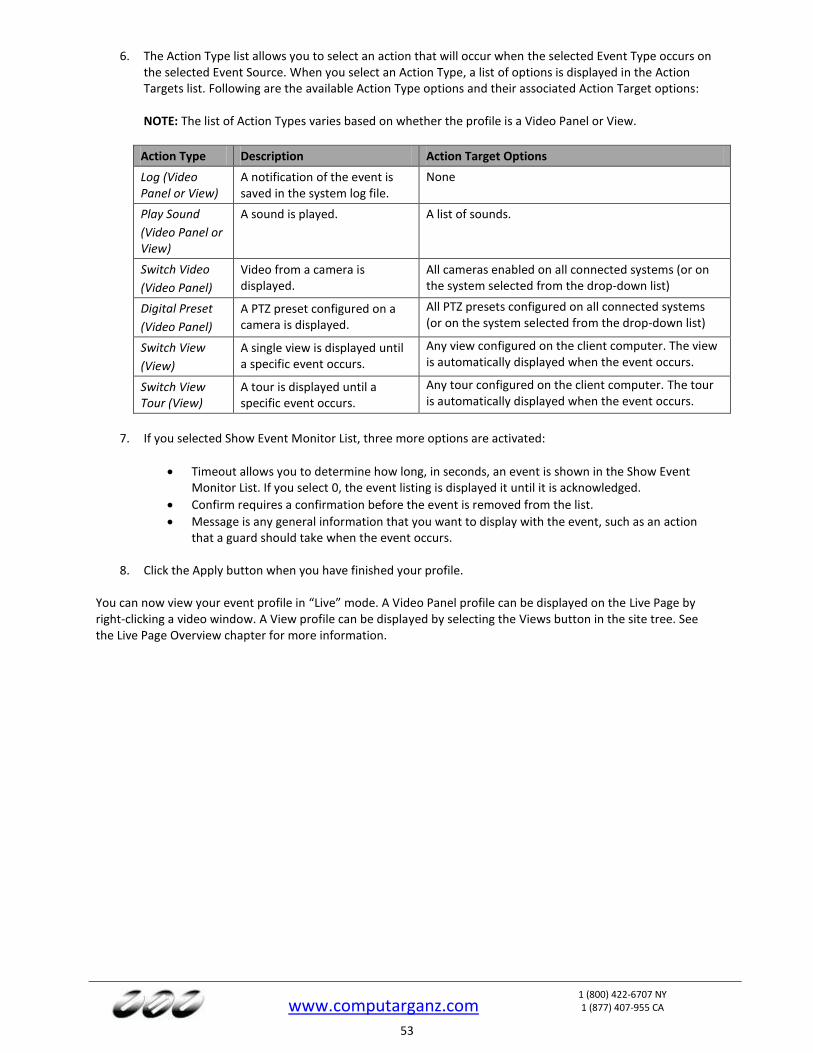
www.computarganz.com
1 (800) 422-6707 NY 1 (877) 407-955 CA
53
6. The Action Type list allows you to select an action that will occur when the selected Event Type occurs on the selected Event Source. When you select an Action Type, a list of options is displayed in the Action Targets list. Following are the available Action Type options and their associated Action Target options:
NOTE: The list of Action Types varies based on whether the profile is a Video Panel or View.
Action Type Description Action Target Options
Log (Video Panel or View)
A notification of the event is saved in the system log file.
None
Play Sound
(Video Panel or View)
A sound is played. A list of sounds.
Switch Video
(Video Panel)
Video from a camera is displayed.
All cameras enabled on all connected systems (or on the system selected from the drop-down list)
Digital Preset
(Video Panel)
A PTZ preset configured on a camera is displayed.
All PTZ presets configured on all connected systems (or on the system selected from the drop-down list)
Switch View
(View)
A single view is displayed until a specific event occurs.
Any view configured on the client computer. The view is automatically displayed when the event occurs.
Switch View Tour (View)
A tour is displayed until a specific event occurs.
Any tour configured on the client computer. The tour is automatically displayed when the event occurs.
7. If you selected Show Event Monitor List, three more options are activated:
Timeout allows you to determine how long, in seconds, an event is shown in the Show Event Monitor List. If you select 0, the event listing is displayed it until it is acknowledged.
Confirm requires a confirmation before the event is removed from the list.
Message is any general information that you want to display with the event, such as an action that a guard should take when the event occurs.
8. Click the Apply button when you have finished your profile.
You can now view your event profile in “Live” mode. A Video Panel profile can be displayed on the Live Page by right-clicking a video window. A View profile can be displayed by selecting the Views button in the site tree. See the Live Page Overview chapter for more information.
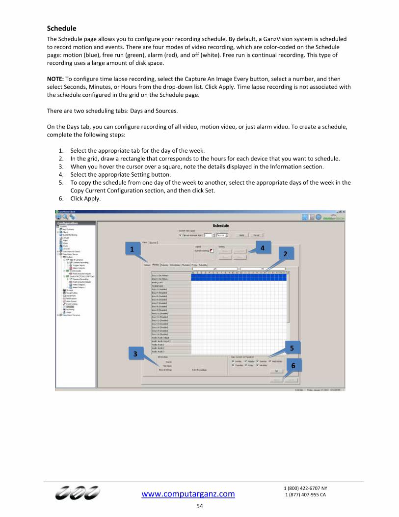
www.computarganz.com
1 (800) 422-6707 NY 1 (877) 407-955 CA
54
Schedule
The Schedule page allows you to configure your recording schedule. By default, a GanzVision system is scheduled to record motion and events. There are four modes of video recording, which are color-coded on the Schedule page: motion (blue), free run (green), alarm (red), and off (white). Free run is continual recording. This type of recording uses a large amount of disk space. NOTE: To configure time lapse recording, select the Capture An Image Every button, select a number, and then select Seconds, Minutes, or Hours from the drop-down list. Click Apply. Time lapse recording is not associated with the schedule configured in the grid on the Schedule page. There are two scheduling tabs: Days and Sources. On the Days tab, you can configure recording of all video, motion video, or just alarm video. To create a schedule, complete the following steps:
1. Select the appropriate tab for the day of the week. 2. In the grid, draw a rectangle that corresponds to the hours for each device that you want to schedule. 3. When you hover the cursor over a square, note the details displayed in the Information section. 4. Select the appropriate Setting button. 5. To copy the schedule from one day of the week to another, select the appropriate days of the week in the
Copy Current Configuration section, and then click Set. 6. Click Apply.
1 2
3
4
5
6
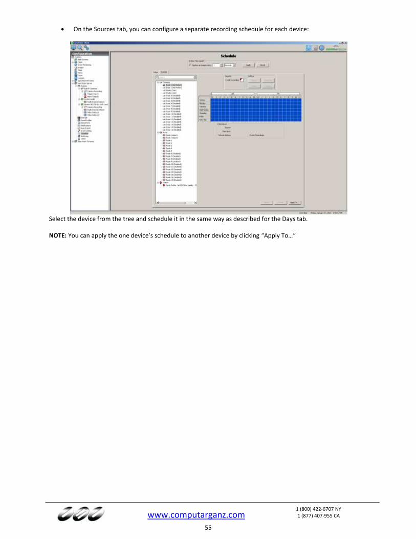
www.computarganz.com
1 (800) 422-6707 NY 1 (877) 407-955 CA
55
On the Sources tab, you can configure a separate recording schedule for each device:
Select the device from the tree and schedule it in the same way as described for the Days tab. NOTE: You can apply the one device’s schedule to another device by clicking “Apply To…”
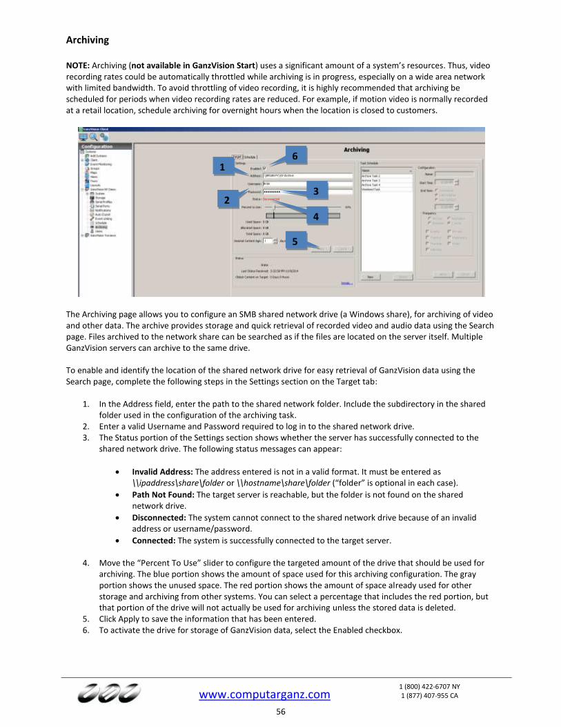
www.computarganz.com
1 (800) 422-6707 NY 1 (877) 407-955 CA
56
Archiving
NOTE: Archiving (not available in GanzVision Start) uses a significant amount of a system’s resources. Thus, video recording rates could be automatically throttled while archiving is in progress, especially on a wide area network with limited bandwidth. To avoid throttling of video recording, it is highly recommended that archiving be scheduled for periods when video recording rates are reduced. For example, if motion video is normally recorded at a retail location, schedule archiving for overnight hours when the location is closed to customers.
The Archiving page allows you to configure an SMB shared network drive (a Windows share), for archiving of video and other data. The archive provides storage and quick retrieval of recorded video and audio data using the Search page. Files archived to the network share can be searched as if the files are located on the server itself. Multiple GanzVision servers can archive to the same drive.
To enable and identify the location of the shared network drive for easy retrieval of GanzVision data using the Search page, complete the following steps in the Settings section on the Target tab:
1. In the Address field, enter the path to the shared network folder. Include the subdirectory in the shared folder used in the configuration of the archiving task.
2. Enter a valid Username and Password required to log in to the shared network drive. 3. The Status portion of the Settings section shows whether the server has successfully connected to the
shared network drive. The following status messages can appear:
Invalid Address: The address entered is not in a valid format. It must be entered as \\ipaddress\share\folder or \\hostname\share\folder (“folder” is optional in each case).
Path Not Found: The target server is reachable, but the folder is not found on the shared network drive.
Disconnected: The system cannot connect to the shared network drive because of an invalid address or username/password.
Connected: The system is successfully connected to the target server.
4. Move the “Percent To Use” slider to configure the targeted amount of the drive that should be used for archiving. The blue portion shows the amount of space used for this archiving configuration. The gray portion shows the unused space. The red portion shows the amount of space already used for other storage and archiving from other systems. You can select a percentage that includes the red portion, but that portion of the drive will not actually be used for archiving unless the stored data is deleted.
5. Click Apply to save the information that has been entered. 6. To activate the drive for storage of GanzVision data, select the Enabled checkbox.
2 3
4
6
5
1
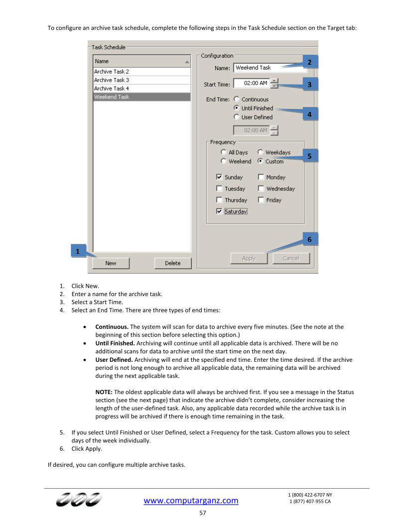
www.computarganz.com
1 (800) 422-6707 NY 1 (877) 407-955 CA
57
To configure an archive task schedule, complete the following steps in the Task Schedule section on the Target tab:
1. Click New. 2. Enter a name for the archive task. 3. Select a Start Time. 4. Select an End Time. There are three types of end times:
Continuous. The system will scan for data to archive every five minutes. (See the note at the beginning of this section before selecting this option.)
Until Finished. Archiving will continue until all applicable data is archived. There will be no additional scans for data to archive until the start time on the next day.
User Defined. Archiving will end at the specified end time. Enter the time desired. If the archive period is not long enough to archive all applicable data, the remaining data will be archived during the next applicable task.
NOTE: The oldest applicable data will always be archived first. If you see a message in the Status section (see the next page) that indicate the archive didn’t complete, consider increasing the length of the user-defined task. Also, any applicable data recorded while the archive task is in progress will be archived if there is enough time remaining in the task.
5. If you select Until Finished or User Defined, select a Frequency for the task. Custom allows you to select
days of the week individually. 6. Click Apply.
If desired, you can configure multiple archive tasks.
1
2
3
4
5
6
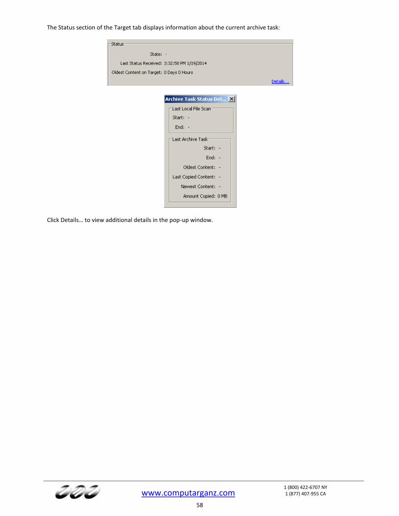
www.computarganz.com
1 (800) 422-6707 NY 1 (877) 407-955 CA
58
The Status section of the Target tab displays information about the current archive task:
Click Details… to view additional details in the pop-up window.
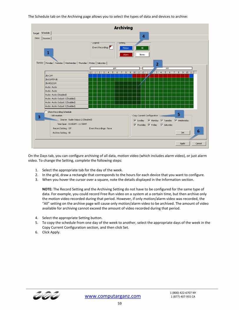
www.computarganz.com
1 (800) 422-6707 NY 1 (877) 407-955 CA
59
The Schedule tab on the Archiving page allows you to select the types of data and devices to archive:
On the Days tab, you can configure archiving of all data, motion video (which includes alarm video), or just alarm video. To change the Setting, complete the following steps:
1. Select the appropriate tab for the day of the week. 2. In the grid, draw a rectangle that corresponds to the hours for each device that you want to configure. 3. When you hover the cursor over a square, note the details displayed in the Information section.
NOTE: The Record Setting and the Archiving Setting do not have to be configured for the same type of data. For example, you could record Free Run video on a system at a certain time, but then archive only the motion video recorded during that period. However, if only motion/alarm video was recorded, the “All” setting on the archive page will cause only motion/alarm video to be archived. The amount of video available for archiving cannot exceed the amount of video recorded during that period.
4. Select the appropriate Setting button. 5. To copy the schedule from one day of the week to another, select the appropriate days of the week in the
Copy Current Configuration section, and then click Set. 6. Click Apply.
1
2
4
5 3
6

www.computarganz.com
1 (800) 422-6707 NY 1 (877) 407-955 CA
60
On the Sources tab, you can configure a separate archiving schedule for each device:
Simply select a device from the tree and then configure archiving the same way as described for the Days tab. NOTE: You can apply the one device’s schedule to another device by clicking “Apply To…”
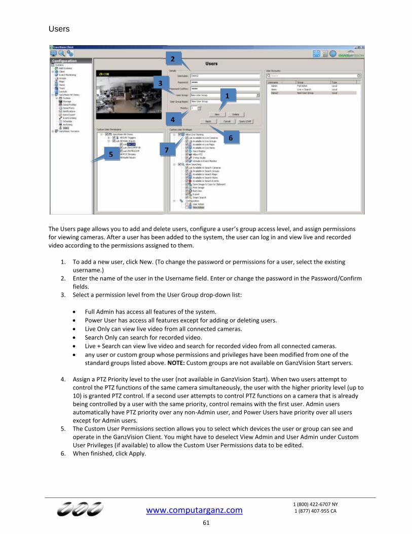
www.computarganz.com
1 (800) 422-6707 NY 1 (877) 407-955 CA
61
Users
The Users page allows you to add and delete users, configure a user’s group access level, and assign permissions for viewing cameras. After a user has been added to the system, the user can log in and view live and recorded video according to the permissions assigned to them.
1. To add a new user, click New. (To change the password or permissions for a user, select the existing username.)
2. Enter the name of the user in the Username field. Enter or change the password in the Password/Confirm fields.
3. Select a permission level from the User Group drop-down list:
Full Admin has access all features of the system.
Power User has access all features except for adding or deleting users.
Live Only can view live video from all connected cameras.
Search Only can search for recorded video.
Live + Search can view live video and search for recorded video from all connected cameras.
any user or custom group whose permissions and privileges have been modified from one of the standard groups listed above. NOTE: Custom groups are not available on GanzVision Start servers.
4. Assign a PTZ Priority level to the user (not available in GanzVision Start). When two users attempt to control the PTZ functions of the same camera simultaneously, the user with the higher priority level (up to 10) is granted PTZ control. If a second user attempts to control PTZ functions on a camera that is already being controlled by a user with the same priority, control remains with the first user. Admin users automatically have PTZ priority over any non-Admin user, and Power Users have priority over all users except for Admin users.
5. The Custom User Permissions section allows you to select which devices the user or group can see and operate in the GanzVision Client. You might have to deselect View Admin and User Admin under Custom User Privileges (if available) to allow the Custom User Permissions data to be edited.
6. When finished, click Apply.
1
2
3
5
4
6
7
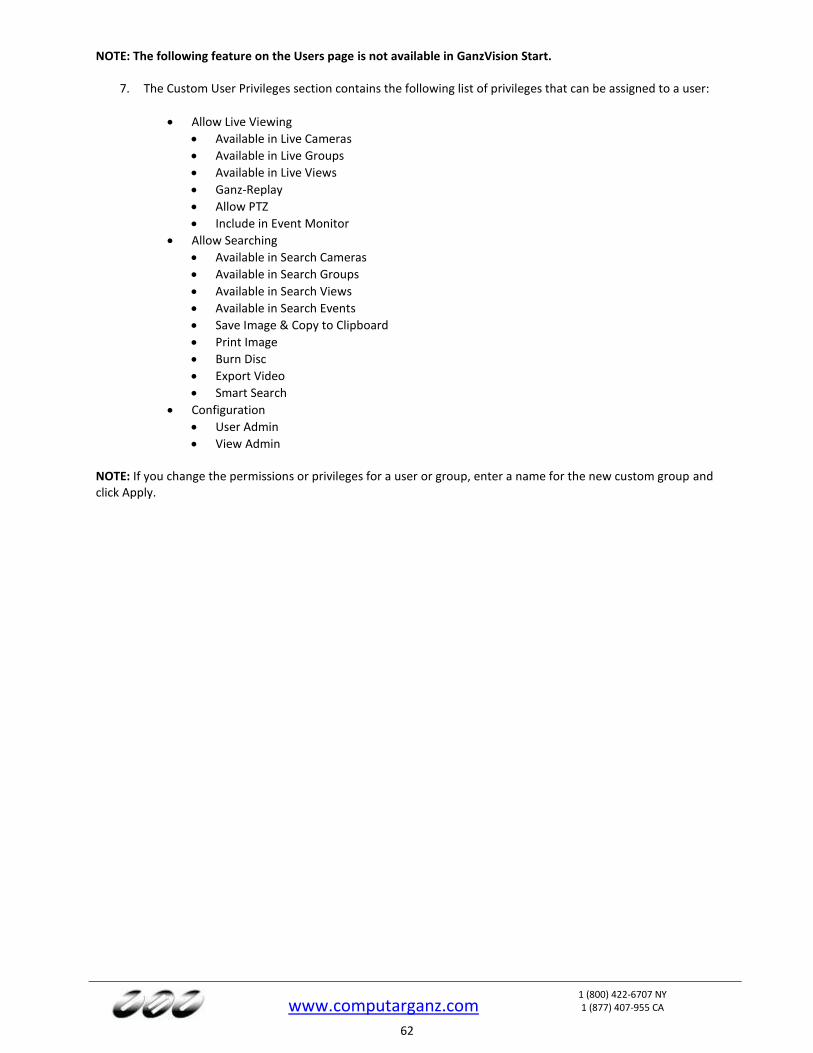
www.computarganz.com
1 (800) 422-6707 NY 1 (877) 407-955 CA
62
NOTE: The following feature on the Users page is not available in GanzVision Start.
7. The Custom User Privileges section contains the following list of privileges that can be assigned to a user:
Allow Live Viewing
Available in Live Cameras
Available in Live Groups
Available in Live Views
Ganz-Replay
Allow PTZ
Include in Event Monitor
Allow Searching
Available in Search Cameras
Available in Search Groups
Available in Search Views
Available in Search Events
Save Image & Copy to Clipboard
Print Image
Burn Disc
Export Video
Smart Search
Configuration
User Admin
View Admin NOTE: If you change the permissions or privileges for a user or group, enter a name for the new custom group and click Apply.

www.computarganz.com
1 (800) 422-6707 NY 1 (877) 407-955 CA
63
Systems
The Systems page lists all added systems, along with their serial number, IP address/hostname, connection status, license type, MAC address, subscription information, version information, status (such as, Normal, Alarm, or Motion), and days of recorded video. NOTE: To display or remove a column on the Systems page, right-click any column header and select the column from the pop-up menu. The following actions can be performed on the Systems page:
To connect to or disconnect a system, right-click its connection status and select a Connect option or Disconnect from the pop-up menu. To connect to or disconnect multiple consecutive systems simultaneously, click on the connection status for the first system, and then press Shift while you drag the cursor up or down (and then right-click).
To view the System Information page for a system, double-click the information listed in any column for that system.
To view model number and serial number information for a system, right-click the system name.
To view a MAC address and license key for a system and copy it to the clipboard, right-click its information in the License, MAC Address, or Subscription column for that system and select Copy to Clipboard (select the right arrow if necessary to see that option). You can then paste the information into an email or other applications.
To update a license key for a system, right-click its information in the License column, select Update, and select one of the options. If you select “Update the License from File”, you can browse to a .KEY file that contains license information and click Open. If you select “Update the License from Text”, you can type the license key manually and click OK.
NOTE: Alternatively, you can click Import Licenses at the bottom of the page to enter multiple licenses from a .CSV file, or click Export Licenses to compile all listed licenses into a .CSV file to import into another client.
To view additional version information for a system, right-click the information in the Version column for that system.
To view additional information about Alarm or Motion status, hover the mouse pointer over the word while it appears in the Status column.
NOTE: If the physical connection between the client computer and server is interrupted while you are connected to the server in GanzVision Client, the Connection Status will be displayed as Network Activity Timeout. The status will then be displayed as Disconnected after a specific amount of time that varies among operating systems.
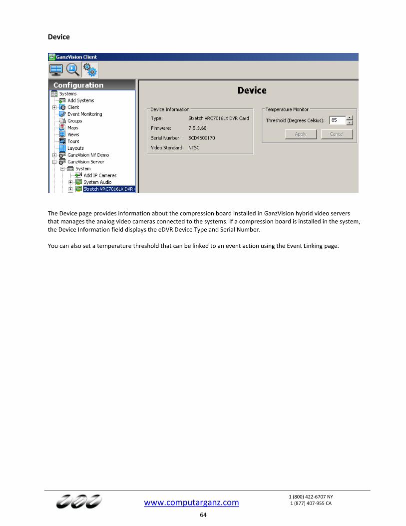
www.computarganz.com
1 (800) 422-6707 NY 1 (877) 407-955 CA
64
Device
The Device page provides information about the compression board installed in GanzVision hybrid video servers that manages the analog video cameras connected to the systems. If a compression board is installed in the system, the Device Information field displays the eDVR Device Type and Serial Number. You can also set a temperature threshold that can be linked to an event action using the Event Linking page.
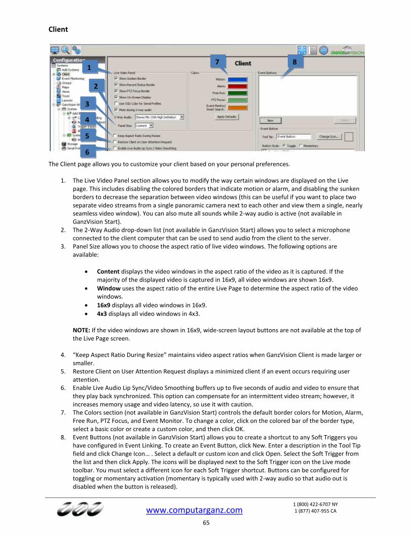
www.computarganz.com
1 (800) 422-6707 NY 1 (877) 407-955 CA
65
Client
The Client page allows you to customize your client based on your personal preferences.
1. The Live Video Panel section allows you to modify the way certain windows are displayed on the Live page. This includes disabling the colored borders that indicate motion or alarm, and disabling the sunken borders to decrease the separation between video windows (this can be useful if you want to place two separate video streams from a single panoramic camera next to each other and view them a single, nearly seamless video window). You can also mute all sounds while 2-way audio is active (not available in GanzVision Start).
2. The 2-Way Audio drop-down list (not available in GanzVision Start) allows you to select a microphone connected to the client computer that can be used to send audio from the client to the server.
3. Panel Size allows you to choose the aspect ratio of live video windows. The following options are available:
Content displays the video windows in the aspect ratio of the video as it is captured. If the majority of the displayed video is captured in 16x9, all video windows are shown 16x9.
Window uses the aspect ratio of the entire Live Page to determine the aspect ratio of the video windows.
16x9 displays all video windows in 16x9.
4x3 displays all video windows in 4x3.
NOTE: If the video windows are shown in 16x9, wide-screen layout buttons are not available at the top of the Live Page screen.
4. “Keep Aspect Ratio During Resize” maintains video aspect ratios when GanzVision Client is made larger or smaller.
5. Restore Client on User Attention Request displays a minimized client if an event occurs requiring user attention.
6. Enable Live Audio Lip Sync/Video Smoothing buffers up to five seconds of audio and video to ensure that they play back synchronized. This option can compensate for an intermittent video stream; however, it increases memory usage and video latency, so use it with caution.
7. The Colors section (not available in GanzVision Start) controls the default border colors for Motion, Alarm, Free Run, PTZ Focus, and Event Monitor. To change a color, click on the colored bar of the border type, select a basic color or create a custom color, and then click OK.
8. Event Buttons (not available in GanzVision Start) allows you to create a shortcut to any Soft Triggers you have configured in Event Linking. To create an Event Button, click New. Enter a description in the Tool Tip field and click Change Icon… . Select a default or custom icon and click Open. Select the Soft Trigger from the list and then click Apply. The icons will be displayed next to the Soft Trigger icon on the Live mode toolbar. You must select a different icon for each Soft Trigger shortcut. Buttons can be configured for toggling or momentary activation (momentary is typically used with 2-way audio so that audio out is disabled when the button is released).
1
3
4
5
2
6
7 8
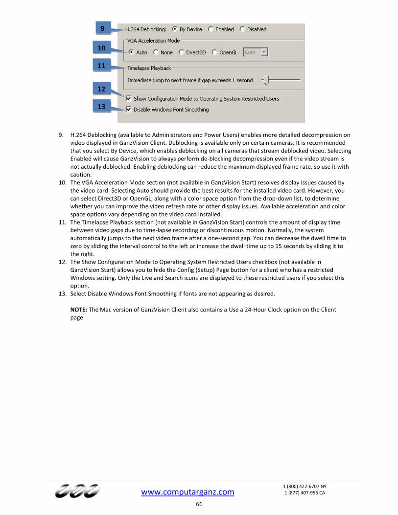
www.computarganz.com
1 (800) 422-6707 NY 1 (877) 407-955 CA
66
9. H.264 Deblocking (available to Administrators and Power Users) enables more detailed decompression on video displayed in GanzVision Client. Deblocking is available only on certain cameras. It is recommended that you select By Device, which enables deblocking on all cameras that stream deblocked video. Selecting Enabled will cause GanzVision to always perform de-blocking decompression even if the video stream is not actually deblocked. Enabling deblocking can reduce the maximum displayed frame rate, so use it with caution.
10. The VGA Acceleration Mode section (not available in GanzVision Start) resolves display issues caused by the video card. Selecting Auto should provide the best results for the installed video card. However, you can select Direct3D or OpenGL, along with a color space option from the drop-down list, to determine whether you can improve the video refresh rate or other display issues. Available acceleration and color space options vary depending on the video card installed.
11. The Timelapse Playback section (not available in GanzVision Start) controls the amount of display time between video gaps due to time-lapse recording or discontinuous motion. Normally, the system automatically jumps to the next video frame after a one-second gap. You can decrease the dwell time to zero by sliding the interval control to the left or increase the dwell time up to 15 seconds by sliding it to the right.
12. The Show Configuration Mode to Operating System Restricted Users checkbox (not available in GanzVision Start) allows you to hide the Config (Setup) Page button for a client who has a restricted Windows setting. Only the Live and Search icons are displayed to these restricted users if you select this option.
13. Select Disable Windows Font Smoothing if fonts are not appearing as desired. NOTE: The Mac version of GanzVision Client also contains a Use a 24-Hour Clock option on the Client page.
9
10
11
12
13
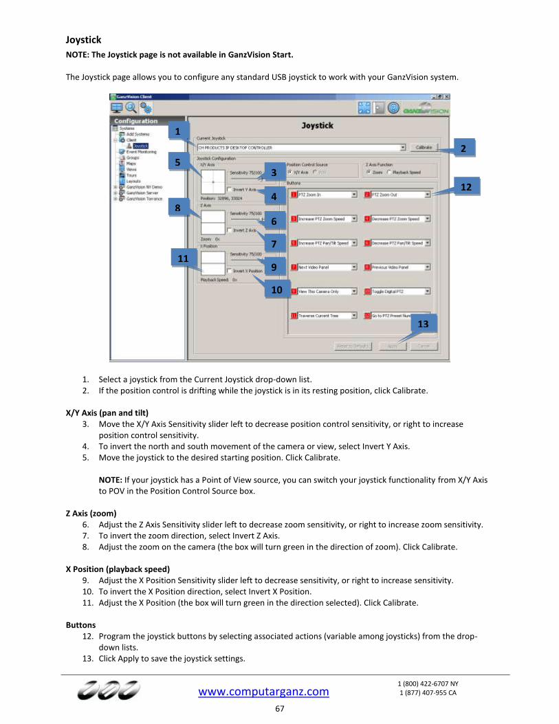
www.computarganz.com
1 (800) 422-6707 NY 1 (877) 407-955 CA
67
Joystick
NOTE: The Joystick page is not available in GanzVision Start. The Joystick page allows you to configure any standard USB joystick to work with your GanzVision system.
1. Select a joystick from the Current Joystick drop-down list. 2. If the position control is drifting while the joystick is in its resting position, click Calibrate.
X/Y Axis (pan and tilt)
3. Move the X/Y Axis Sensitivity slider left to decrease position control sensitivity, or right to increase position control sensitivity.
4. To invert the north and south movement of the camera or view, select Invert Y Axis. 5. Move the joystick to the desired starting position. Click Calibrate.
NOTE: If your joystick has a Point of View source, you can switch your joystick functionality from X/Y Axis to POV in the Position Control Source box.
Z Axis (zoom) 6. Adjust the Z Axis Sensitivity slider left to decrease zoom sensitivity, or right to increase zoom sensitivity. 7. To invert the zoom direction, select Invert Z Axis. 8. Adjust the zoom on the camera (the box will turn green in the direction of zoom). Click Calibrate.
X Position (playback speed)
9. Adjust the X Position Sensitivity slider left to decrease sensitivity, or right to increase sensitivity. 10. To invert the X Position direction, select Invert X Position. 11. Adjust the X Position (the box will turn green in the direction selected). Click Calibrate.
Buttons
12. Program the joystick buttons by selecting associated actions (variable among joysticks) from the drop-down lists.
13. Click Apply to save the joystick settings.
1
2
3
4
5
6
9
8
7
10
11
13
12
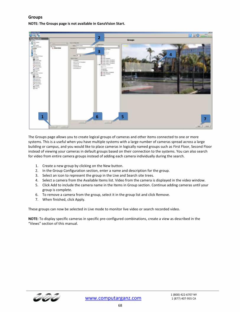
www.computarganz.com
1 (800) 422-6707 NY 1 (877) 407-955 CA
68
Groups
NOTE: The Groups page is not available in GanzVision Start.
The Groups page allows you to create logical groups of cameras and other items connected to one or more systems. This is a useful when you have multiple systems with a large number of cameras spread across a large building or campus, and you would like to place cameras in logically named groups such as First Floor, Second Floor instead of viewing your cameras in default groups based on their connection to the systems. You can also search for video from entire camera groups instead of adding each camera individually during the search.
1. Create a new group by clicking on the New button. 2. In the Group Configuration section, enter a name and description for the group. 3. Select an icon to represent the group in the Live and Search site trees. 4. Select a camera from the Available Items list. Video from the camera is displayed in the video window. 5. Click Add to include the camera name in the Items in Group section. Continue adding cameras until your
group is complete. 6. To remove a camera from the group, select it in the group list and click Remove. 7. When finished, click Apply.
These groups can now be selected in Live mode to monitor live video or search recorded video. NOTE: To display specific cameras in specific pre-configured combinations, create a view as described in the “Views” section of this manual.
1
2
3 4
5 6 7
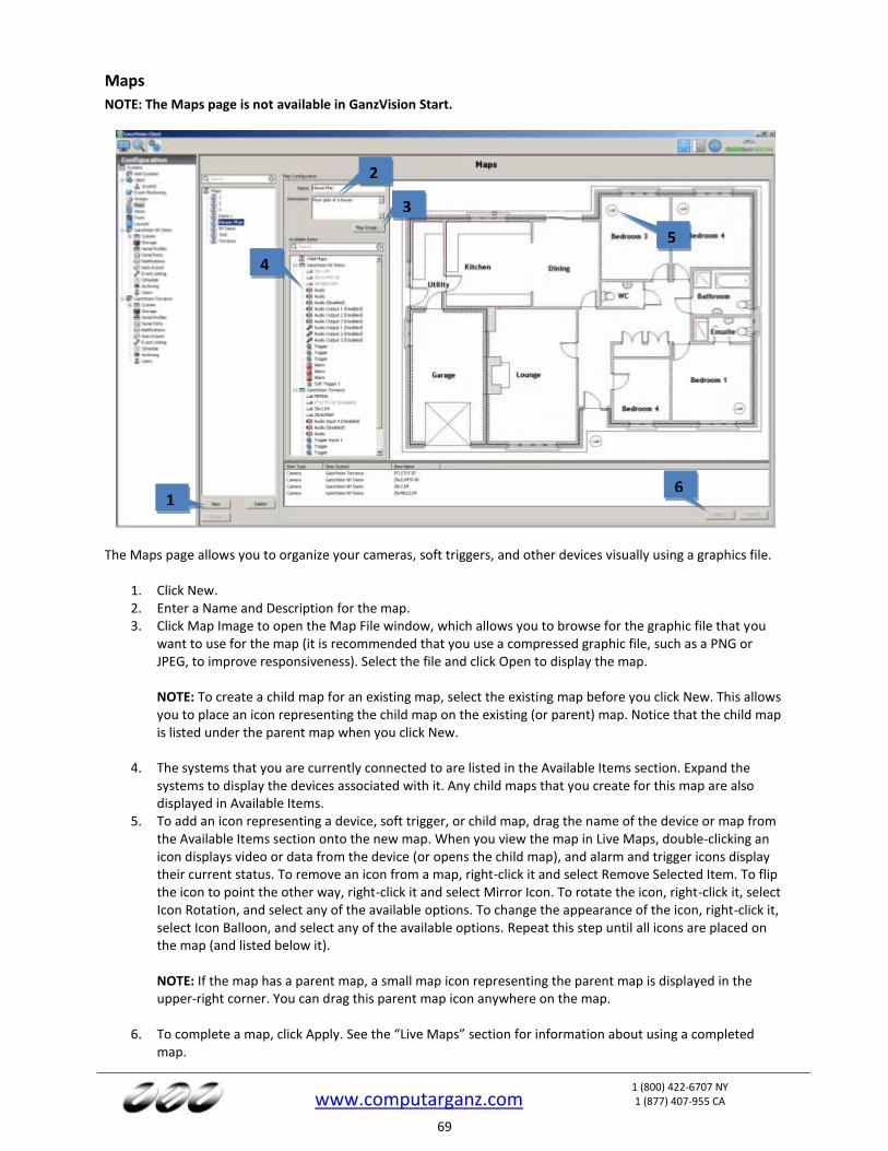
www.computarganz.com
1 (800) 422-6707 NY 1 (877) 407-955 CA
69
Maps
NOTE: The Maps page is not available in GanzVision Start.
The Maps page allows you to organize your cameras, soft triggers, and other devices visually using a graphics file.
1. Click New. 2. Enter a Name and Description for the map. 3. Click Map Image to open the Map File window, which allows you to browse for the graphic file that you
want to use for the map (it is recommended that you use a compressed graphic file, such as a PNG or JPEG, to improve responsiveness). Select the file and click Open to display the map. NOTE: To create a child map for an existing map, select the existing map before you click New. This allows you to place an icon representing the child map on the existing (or parent) map. Notice that the child map is listed under the parent map when you click New.
4. The systems that you are currently connected to are listed in the Available Items section. Expand the
systems to display the devices associated with it. Any child maps that you create for this map are also displayed in Available Items.
5. To add an icon representing a device, soft trigger, or child map, drag the name of the device or map from the Available Items section onto the new map. When you view the map in Live Maps, double-clicking an icon displays video or data from the device (or opens the child map), and alarm and trigger icons display their current status. To remove an icon from a map, right-click it and select Remove Selected Item. To flip the icon to point the other way, right-click it and select Mirror Icon. To rotate the icon, right-click it, select Icon Rotation, and select any of the available options. To change the appearance of the icon, right-click it, select Icon Balloon, and select any of the available options. Repeat this step until all icons are placed on the map (and listed below it).
NOTE: If the map has a parent map, a small map icon representing the parent map is displayed in the upper-right corner. You can drag this parent map icon anywhere on the map.
6. To complete a map, click Apply. See the “Live Maps” section for information about using a completed
map.
1
2
3
4
5
6
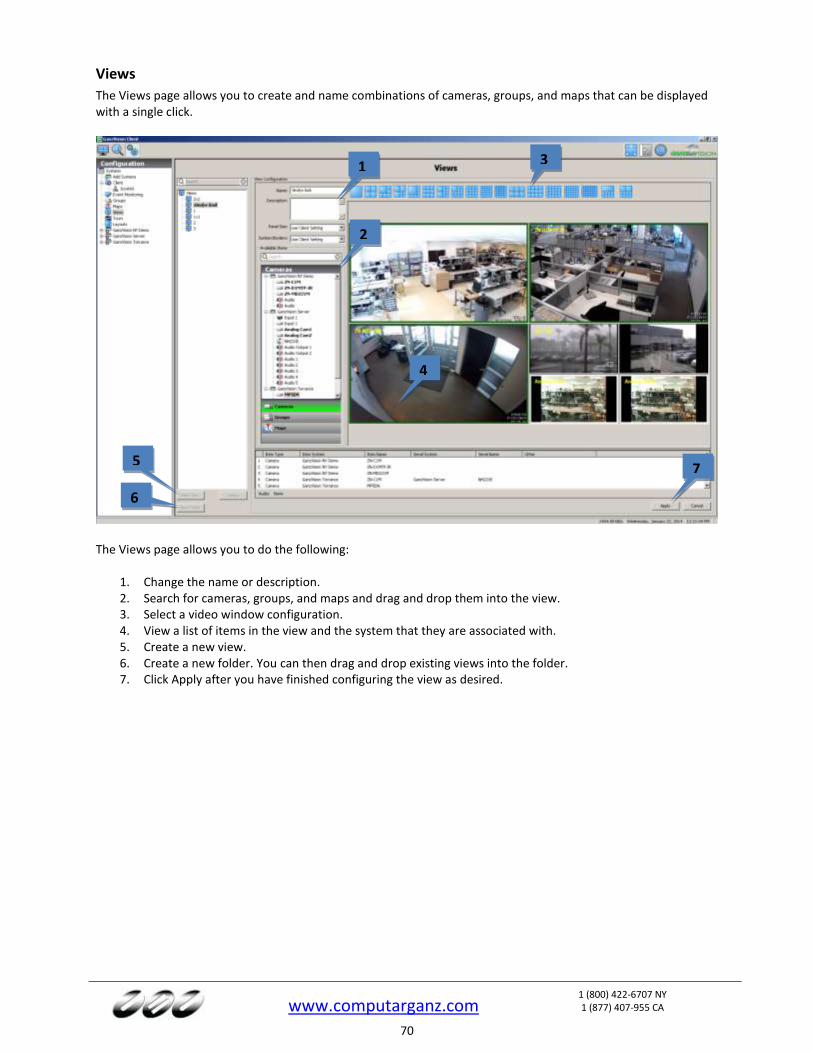
www.computarganz.com
1 (800) 422-6707 NY 1 (877) 407-955 CA
70
Views
The Views page allows you to create and name combinations of cameras, groups, and maps that can be displayed with a single click.
The Views page allows you to do the following:
1. Change the name or description. 2. Search for cameras, groups, and maps and drag and drop them into the view. 3. Select a video window configuration. 4. View a list of items in the view and the system that they are associated with. 5. Create a new view. 6. Create a new folder. You can then drag and drop existing views into the folder. 7. Click Apply after you have finished configuring the view as desired.
1
2
3
4
5
6
7
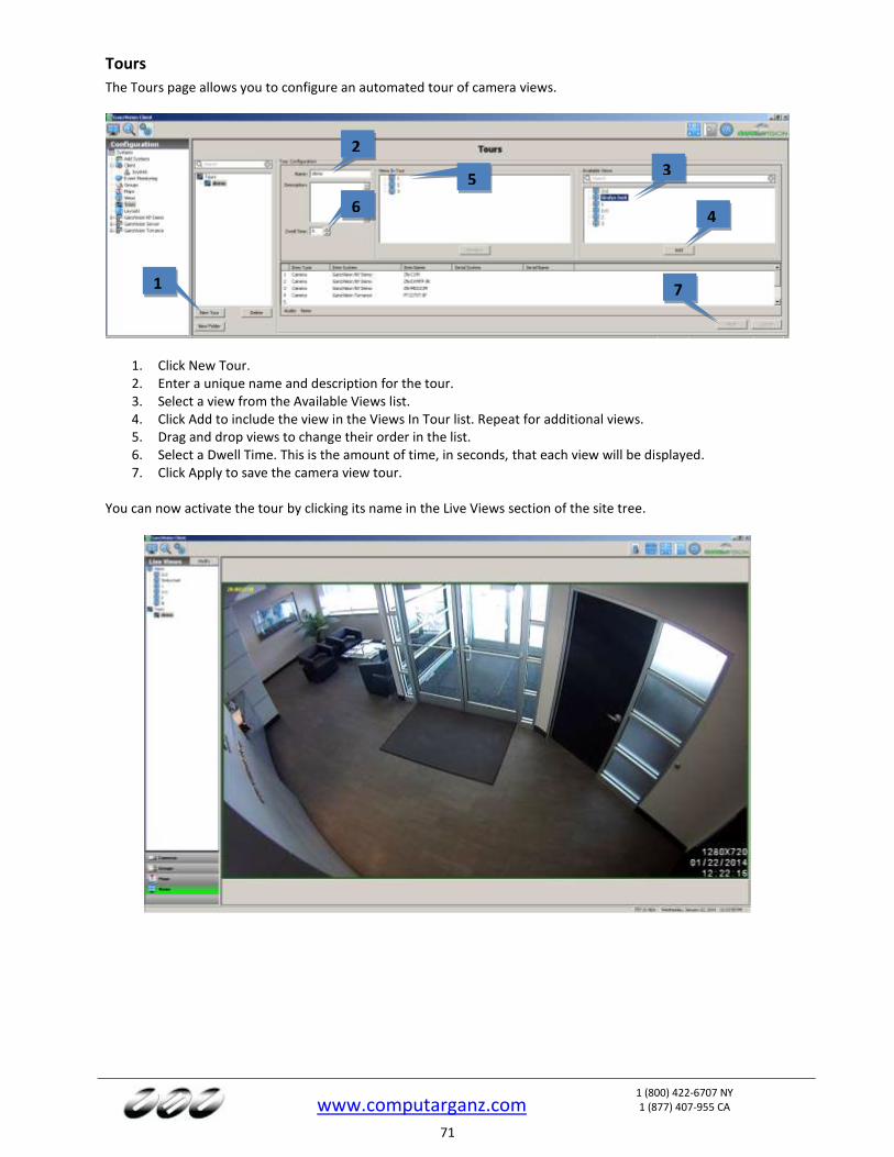
www.computarganz.com
1 (800) 422-6707 NY 1 (877) 407-955 CA
71
Tours
The Tours page allows you to configure an automated tour of camera views.
1. Click New Tour. 2. Enter a unique name and description for the tour. 3. Select a view from the Available Views list. 4. Click Add to include the view in the Views In Tour list. Repeat for additional views. 5. Drag and drop views to change their order in the list. 6. Select a Dwell Time. This is the amount of time, in seconds, that each view will be displayed. 7. Click Apply to save the camera view tour.
You can now activate the tour by clicking its name in the Live Views section of the site tree.
1
2
3
4
5
6
7

www.computarganz.com
1 (800) 422-6707 NY 1 (877) 407-955 CA
72
Layouts
The Layouts page allows you to create custom video window layouts for use on the Live Page. Several basic layouts, such as 1x1, 2x2, and so on, are already available by default. Layouts are limited to a maximum of 48 panels. You can save and search camera views in a custom layout the same way as with default layouts.
To create a custom video window layout, complete the following steps:
1. Click New Layout. 2. Select the layout button that most closely resembles the custom layout that you want to create. 3. Select a video panel, or hold the Shift or Ctrl keys and select multiple video panels. Selected panels are
outlined in green. 4. Select any of the configuration buttons. (These buttons are not activated until you select one or more
panels.) Hover the cursor over each button to view a description of their functions. You can add or delete columns or rows, merge or split panels, and more. You can also merge two windows by clicking a corner of a panel and dragging it.
5. For each selected panel, select the display option (4x3 or 16x9) that corresponds to the type of camera that you would normally display in the panel. To activate the selected display option on all panels, select Apply to All.
6. Select Show Gridlines to compare the size of smaller windows within a larger window. 7. Enter a name and description for the custom layout. 8. Select the size of the entire layout from the Panel Size drop-down list. You can choose 4x3, 16x9, or use
the setting automatically selected by the client based on the client window. 9. Select whether you would like to show or hide sunken borders, or automatically use the setting selected
on the Client page. 10. The Icon indicator shows what the layout icon will look like on the Live Page. 11. Panel Count shows how many panels are included in the layout out of the maximum (48). 12. Click Apply to save the layout. 13. To edit a custom layout, select it from the layout list.
1
2
3
4 5 6
7
8
9
10
11
12
13
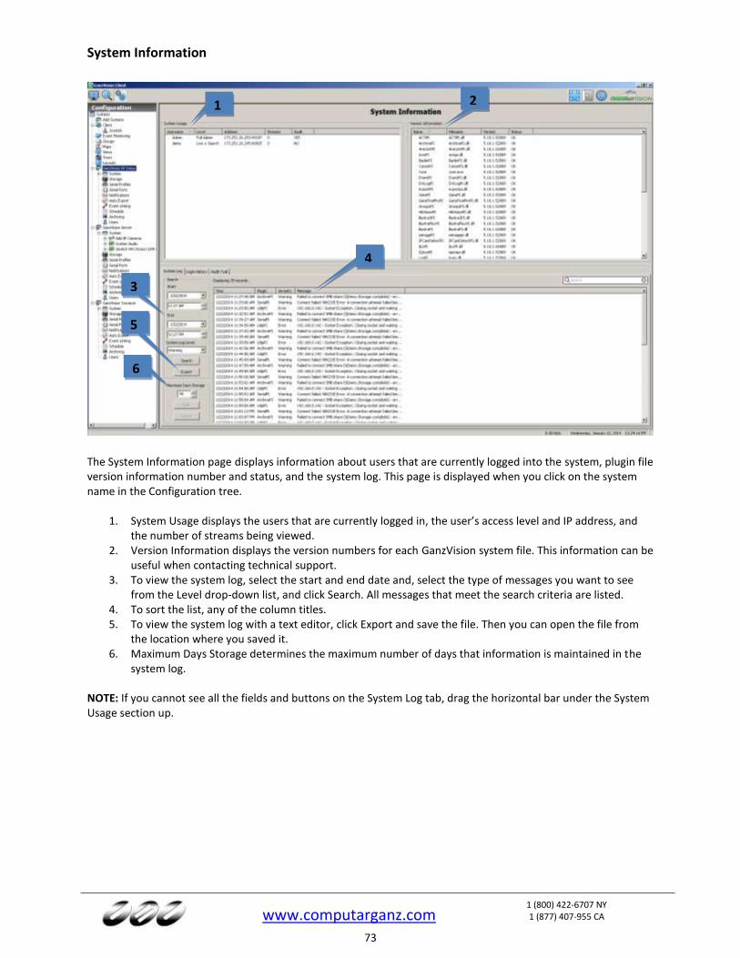
www.computarganz.com
1 (800) 422-6707 NY 1 (877) 407-955 CA
73
System Information
The System Information page displays information about users that are currently logged into the system, plugin file version information number and status, and the system log. This page is displayed when you click on the system name in the Configuration tree.
1. System Usage displays the users that are currently logged in, the user’s access level and IP address, and the number of streams being viewed.
2. Version Information displays the version numbers for each GanzVision system file. This information can be useful when contacting technical support.
3. To view the system log, select the start and end date and, select the type of messages you want to see from the Level drop-down list, and click Search. All messages that meet the search criteria are listed.
4. To sort the list, any of the column titles. 5. To view the system log with a text editor, click Export and save the file. Then you can open the file from
the location where you saved it. 6. Maximum Days Storage determines the maximum number of days that information is maintained in the
system log. NOTE: If you cannot see all the fields and buttons on the System Log tab, drag the horizontal bar under the System Usage section up.
1 2
3
6
5
4
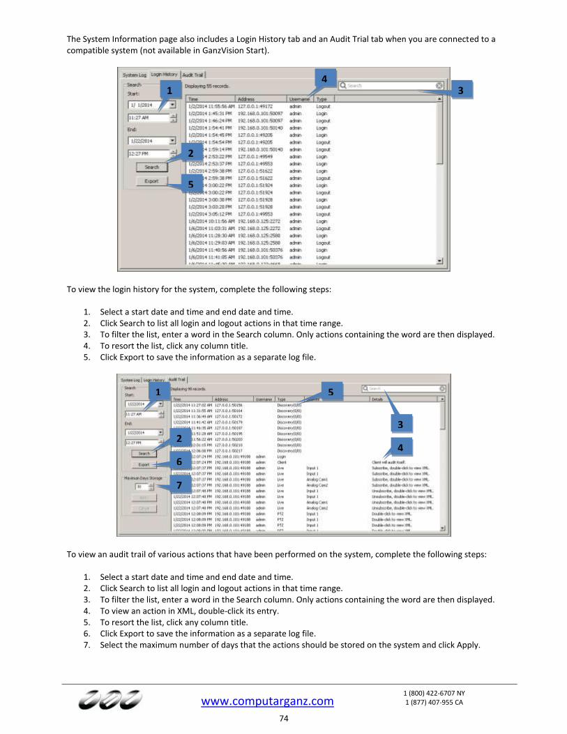
www.computarganz.com
1 (800) 422-6707 NY 1 (877) 407-955 CA
74
The System Information page also includes a Login History tab and an Audit Trial tab when you are connected to a compatible system (not available in GanzVision Start).
To view the login history for the system, complete the following steps:
1. Select a start date and time and end date and time. 2. Click Search to list all login and logout actions in that time range. 3. To filter the list, enter a word in the Search column. Only actions containing the word are then displayed. 4. To resort the list, click any column title. 5. Click Export to save the information as a separate log file.
To view an audit trail of various actions that have been performed on the system, complete the following steps:
1. Select a start date and time and end date and time. 2. Click Search to list all login and logout actions in that time range. 3. To filter the list, enter a word in the Search column. Only actions containing the word are then displayed. 4. To view an action in XML, double-click its entry. 5. To resort the list, click any column title. 6. Click Export to save the information as a separate log file. 7. Select the maximum number of days that the actions should be stored on the system and click Apply.
1
2
3
4
5
1
2
3
4
5
6
7
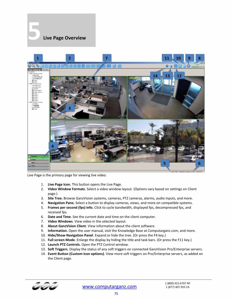
www.computarganz.com
1 (800) 422-6707 NY 1 (877) 407-955 CA
75
5 Live Page Overview
Live Page is the primary page for viewing live video.
1. Live Page Icon. This button opens the Live Page. 2. Video Window Formats. Select a video window layout. (Options vary based on settings on Client
page.) 3. Site Tree. Browse GanzVision systems, cameras, PTZ cameras, alarms, audio inputs, and more. 4. Navigation Pane. Select a button to display cameras, views, and more on compatible systems. 5. Frames per second (fps) info. Click to cycle bandwidth, displayed fps, decompressed fps, and
received fps. 6. Date and Time. See the current date and time on the client computer. 7. Video Windows. View video in the selected layout. 8. About GanzVision Client. View information about the client software. 9. Information. Open the user manual, visit the Knowledge Base at Computarganz.com, and more. 10. Hide/Show Navigation Panel. Expand or hide the tree. (Or press the F4 key.) 11. Full screen Mode. Enlarge the display by hiding the title and task bars. (Or press the F11 key.) 12. Launch PTZ Controls. Open the PTZ Control window. 13. Soft Triggers. Display the status of any soft triggers on connected GanzVision Pro/Enterprise servers. 14. Event Button (Custom Icon options). View more soft triggers on Pro/Enterprise servers, as added on
the Client page.
1 2
3
4
5 6
7 8 9 10 11
12 13 14

www.computarganz.com
1 (800) 422-6707 NY 1 (877) 407-955 CA
76
Layout Panel
You change the layout of the video windows by clicking on one of the Layout buttons. When you select a layout, it becomes the new default. The system automatically fills the video windows with the cameras from your Live Site Tree in the order they are listed. NOTE: The available Layout buttons vary based on the number of cameras connected and the width of the GanzVision Client window. There are several methods for adding cameras to your Video View Panel.
Select a Layout button on the Toolbar.
Double-click a camera name listed in the site tree. The system displays that camera in the upper-left video and fills the rest of the windows in order below that camera in the list.
Drag and drop a camera from the site tree into a video window. The window can be empty or currently displaying video when you do this.
Drag and drop a server name into the layout panel. If the layout includes six video windows, the first six cameras from the server will be displayed.
Press F3 or the joystick button to display the Find Camera dialog. Start typing the name of a connected camera, select the camera when you locate it in the list, and click OK. This feature works best when cameras are uniquely named. For example, if camera names start with numerical characters (such as 1-Front Entrance, 2-Back Entrance, and so on), you can quickly find a camera by simply entering one or two numbers in Find Camera.

www.computarganz.com
1 (800) 422-6707 NY 1 (877) 407-955 CA
77
You can delete a camera from the Video View Panel by right-clicking anywhere in the square and selecting Disconnect Streaming Video.
You can also access the Camera Settings page directly from Live Page by selecting Properties, and then clicking the OK button.
NOTE: To view the video window panel in the largest area possible, press Alt and Enter simultaneously on the keyboard. This combines the previously mentioned keyboard functions (F4 to hide the navigation tree and F11 to hide the title and task bars) with the F8 function, which hides the message bar, the date/time bar, and the toolbar. To reverse this mode and show all the hidden items, press Alt+Enter again.
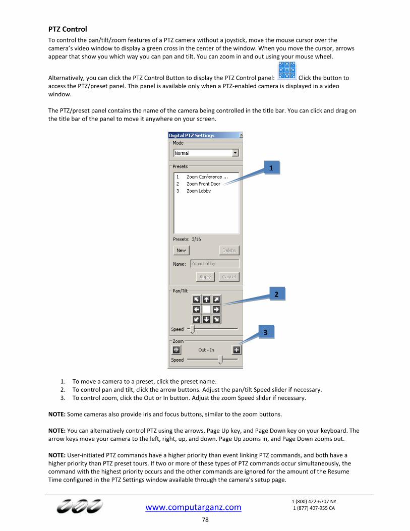
www.computarganz.com
1 (800) 422-6707 NY 1 (877) 407-955 CA
78
PTZ Control
To control the pan/tilt/zoom features of a PTZ camera without a joystick, move the mouse cursor over the camera’s video window to display a green cross in the center of the window. When you move the cursor, arrows appear that show you which way you can pan and tilt. You can zoom in and out using your mouse wheel.
Alternatively, you can click the PTZ Control Button to display the PTZ Control panel: Click the button to access the PTZ/preset panel. This panel is available only when a PTZ-enabled camera is displayed in a video window. The PTZ/preset panel contains the name of the camera being controlled in the title bar. You can click and drag on the title bar of the panel to move it anywhere on your screen.
1. To move a camera to a preset, click the preset name. 2. To control pan and tilt, click the arrow buttons. Adjust the pan/tilt Speed slider if necessary. 3. To control zoom, click the Out or In button. Adjust the zoom Speed slider if necessary.
NOTE: Some cameras also provide iris and focus buttons, similar to the zoom buttons. NOTE: You can alternatively control PTZ using the arrows, Page Up key, and Page Down key on your keyboard. The arrow keys move your camera to the left, right, up, and down. Page Up zooms in, and Page Down zooms out. NOTE: User-initiated PTZ commands have a higher priority than event linking PTZ commands, and both have a higher priority than PTZ preset tours. If two or more of these types of PTZ commands occur simultaneously, the command with the highest priority occurs and the other commands are ignored for the amount of the Resume Time configured in the PTZ Settings window available through the camera’s setup page.
1
2
3
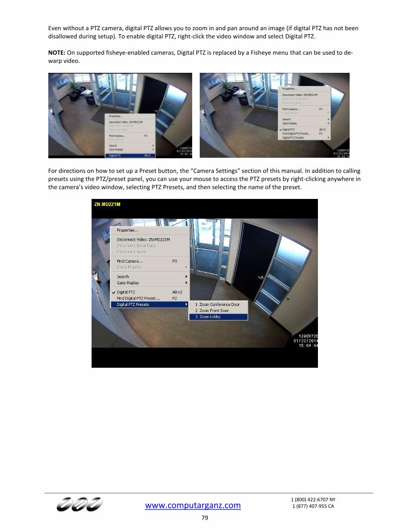
www.computarganz.com
1 (800) 422-6707 NY 1 (877) 407-955 CA
79
Even without a PTZ camera, digital PTZ allows you to zoom in and pan around an image (if digital PTZ has not been disallowed during setup). To enable digital PTZ, right-click the video window and select Digital PTZ. NOTE: On supported fisheye-enabled cameras, Digital PTZ is replaced by a Fisheye menu that can be used to de-warp video.
For directions on how to set up a Preset button, the “Camera Settings” section of this manual. In addition to calling presets using the PTZ/preset panel, you can use your mouse to access the PTZ presets by right-clicking anywhere in the camera’s video window, selecting PTZ Presets, and then selecting the name of the preset.
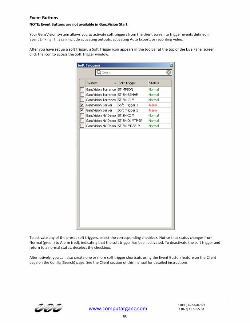
www.computarganz.com
1 (800) 422-6707 NY 1 (877) 407-955 CA
80
Event Buttons
NOTE: Event Buttons are not available in GanzVision Start. Your GanzVision system allows you to activate soft triggers from the client screen to trigger events defined in Event Linking. This can include activating outputs, activating Auto Export, or recording video. After you have set up a soft trigger, a Soft Trigger icon appears in the toolbar at the top of the Live Panel screen. Click the icon to access the Soft Trigger window.
To activate any of the preset soft triggers, select the corresponding checkbox. Notice that status changes from Normal (green) to Alarm (red), indicating that the soft trigger has been activated. To deactivate the soft trigger and return to a normal status, deselect the checkbox. Alternatively, you can also create one or more soft trigger shortcuts using the Event Button feature on the Client page on the Config (Search) page. See the Client section of this manual for detailed instructions.
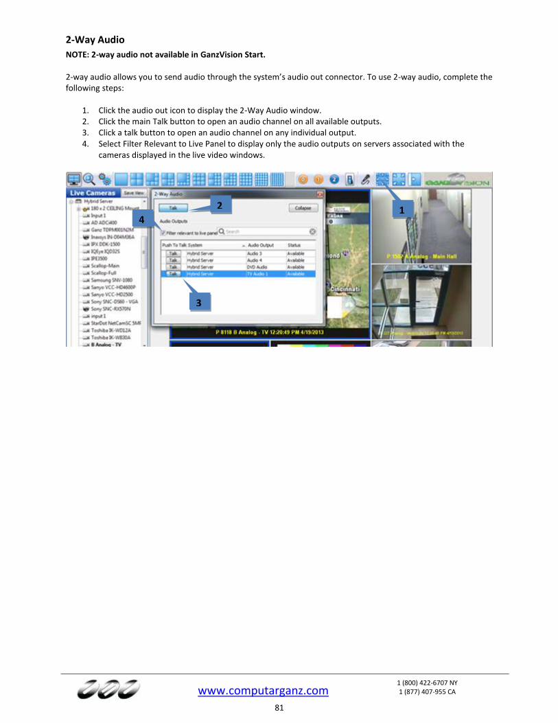
www.computarganz.com
1 (800) 422-6707 NY 1 (877) 407-955 CA
81
2-Way Audio
NOTE: 2-way audio not available in GanzVision Start. 2-way audio allows you to send audio through the system’s audio out connector. To use 2-way audio, complete the following steps:
1. Click the audio out icon to display the 2-Way Audio window. 2. Click the main Talk button to open an audio channel on all available outputs. 3. Click a talk button to open an audio channel on any individual output. 4. Select Filter Relevant to Live Panel to display only the audio outputs on servers associated with the
cameras displayed in the live video windows.
1 2
3
4
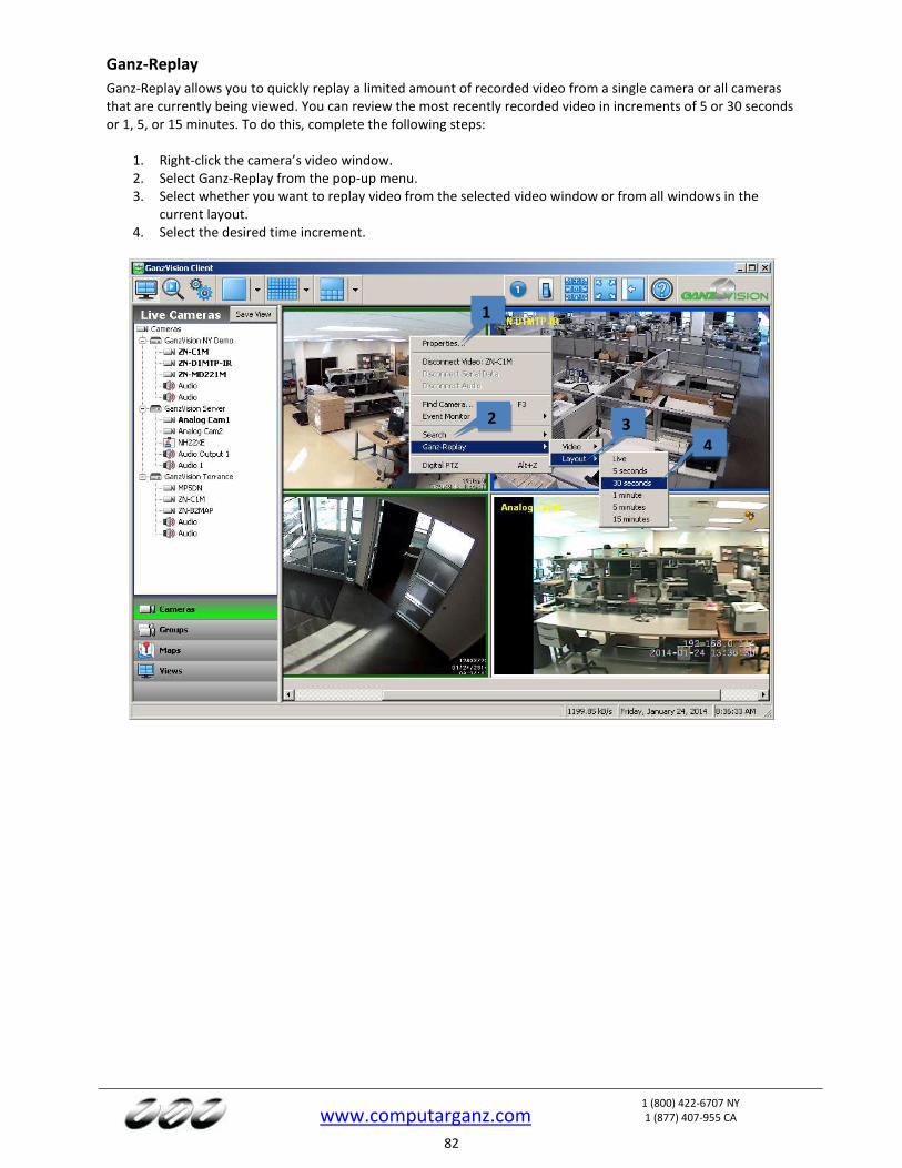
www.computarganz.com
1 (800) 422-6707 NY 1 (877) 407-955 CA
82
Ganz-Replay
Ganz-Replay allows you to quickly replay a limited amount of recorded video from a single camera or all cameras that are currently being viewed. You can review the most recently recorded video in increments of 5 or 30 seconds or 1, 5, or 15 minutes. To do this, complete the following steps:
1. Right-click the camera’s video window. 2. Select Ganz-Replay from the pop-up menu. 3. Select whether you want to replay video from the selected video window or from all windows in the
current layout. 4. Select the desired time increment.
3
4
1
2
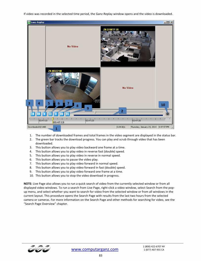
www.computarganz.com
1 (800) 422-6707 NY 1 (877) 407-955 CA
83
If video was recorded in the selected time period, the Ganz-Replay window opens and the video is downloaded.
1. The number of downloaded frames and total frames in the video segment are displayed in the status bar. 2. The green bar tracks the download progress. You can play and scrub through video that has been
downloaded. 3. This button allows you to play video backward one frame at a time. 4. This button allows you to play video in reverse fast (double) speed. 5. This button allows you to play video in reverse in normal speed. 6. This button allows you to pause the video play. 7. This button allows you to play video forward in normal speed. 8. This button allows you to play video forward in fast (double) speed. 9. This button allows you to play video forward one frame at a time. 10. This button allows you to stop the video download in progress.
NOTE: Live Page also allows you to run a quick search of video from the currently selected window or from all displayed video windows. To run a search from Live Page, right-click a video window, select Search from the pop-up menu, and select whether you want to search for video from the selected window or from all windows in the current layout. This procedure opens the Search Page with results from the last two hours from the selected camera or cameras. For more information on the Search Page and other methods for searching for video, see the “Search Page Overview” chapter.
3 4 5 6 7 8
9 10
1
2

www.computarganz.com
1 (800) 422-6707 NY 1 (877) 407-955 CA
84
Live Event Monitoring
NOTE: Live Event Monitoring is not available in GanzVision Start. Event Monitoring allows you to view events that have been detected. To do this, right-click a video window, select Event Monitor, and then select the event profile you want to view.
This displays an orange border around the video window; video is not displayed in the window until an event triggers.
You can stop the Event Monitoring display by right-clicking in the active video panel and disabling the active event monitoring profile. If you configured your profile to Show Event Monitoring List, the Event Monitor box appears below this video window (you can move it and resize it as needed). When a video event takes place, it is automatically listed in the box until you confirm it or its timeout range expires. Click an event line to display video from the associated camera.
1. Click the blue replay button to replay the event as it was triggered. 2. Click the red X to acknowledge the event and remove it from the list.
If you configured your profile in Virtual Matrix Mode, you will not see an Event Monitor box as motion triggers recording. Instead, the video is automatically displayed as motion occurs.
1
2
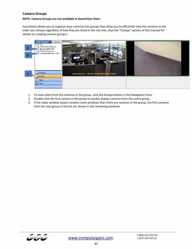
www.computarganz.com
1 (800) 422-6707 NY 1 (877) 407-955 CA
85
Camera Groups
NOTE: Camera Groups are not available in GanzVision Start. GanzVision allows you to organize your cameras into groups that allow you to efficiently view the cameras in the order you choose regardless of how they are listed in the site tree. (See the “Groups” section of this manual for details on creating camera groups.)
1. To view video from the cameras in the group, click the Groups button in the Navigation Pane. 2. Double-click the first camera in the group to quickly display cameras from the entire group. 3. If the video window layout contains more windows than there are cameras in the group, the first cameras
from the next group in the list are shown in the remaining windows.
1
2
3
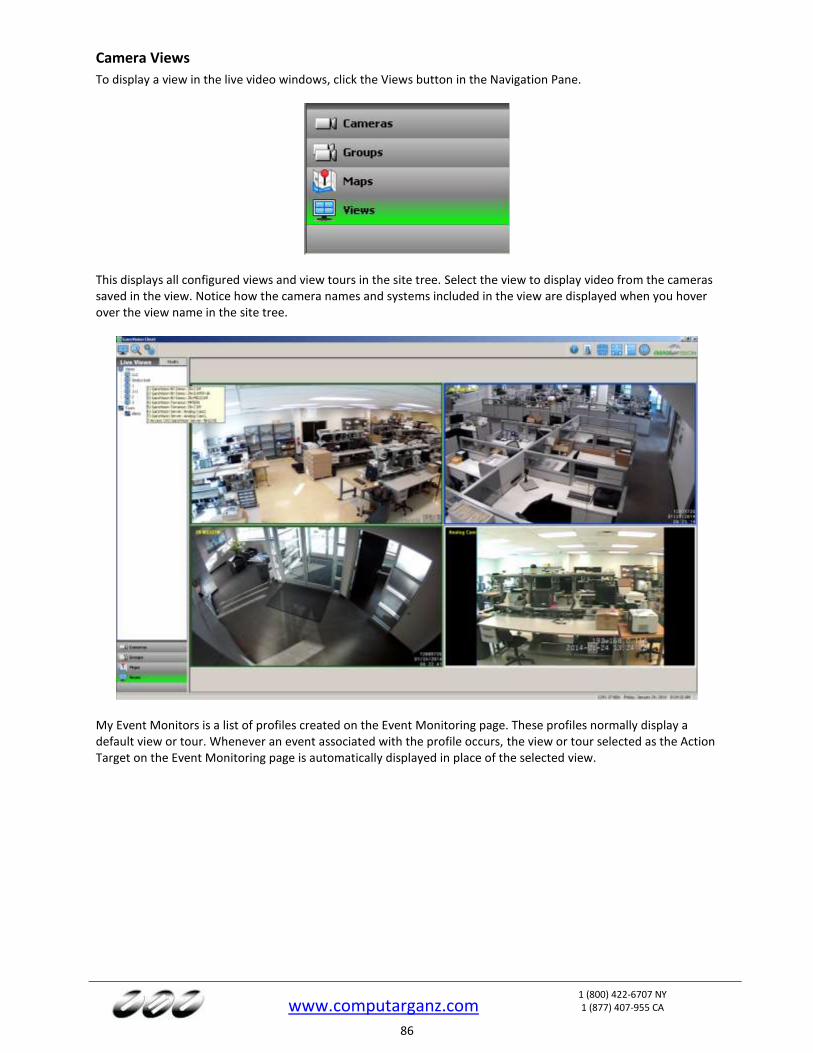
www.computarganz.com
1 (800) 422-6707 NY 1 (877) 407-955 CA
86
Camera Views
To display a view in the live video windows, click the Views button in the Navigation Pane.
This displays all configured views and view tours in the site tree. Select the view to display video from the cameras saved in the view. Notice how the camera names and systems included in the view are displayed when you hover over the view name in the site tree.
My Event Monitors is a list of profiles created on the Event Monitoring page. These profiles normally display a default view or tour. Whenever an event associated with the profile occurs, the view or tour selected as the Action Target on the Event Monitoring page is automatically displayed in place of the selected view.
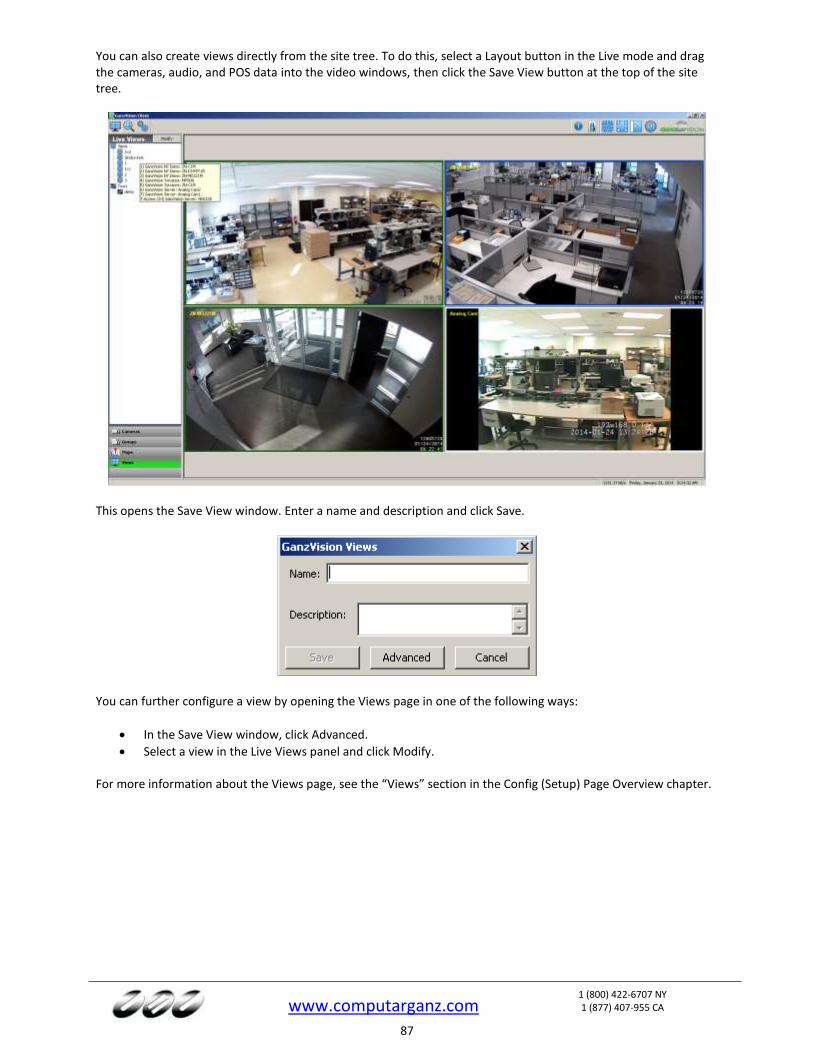
www.computarganz.com
1 (800) 422-6707 NY 1 (877) 407-955 CA
87
You can also create views directly from the site tree. To do this, select a Layout button in the Live mode and drag the cameras, audio, and POS data into the video windows, then click the Save View button at the top of the site tree.
This opens the Save View window. Enter a name and description and click Save.
You can further configure a view by opening the Views page in one of the following ways:
In the Save View window, click Advanced.
Select a view in the Live Views panel and click Modify. For more information about the Views page, see the “Views” section in the Config (Setup) Page Overview chapter.
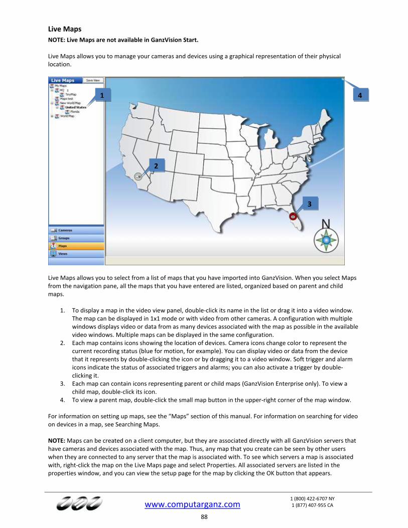
www.computarganz.com
1 (800) 422-6707 NY 1 (877) 407-955 CA
88
Live Maps
NOTE: Live Maps are not available in GanzVision Start. Live Maps allows you to manage your cameras and devices using a graphical representation of their physical location.
Live Maps allows you to select from a list of maps that you have imported into GanzVision. When you select Maps from the navigation pane, all the maps that you have entered are listed, organized based on parent and child maps.
1. To display a map in the video view panel, double-click its name in the list or drag it into a video window. The map can be displayed in 1x1 mode or with video from other cameras. A configuration with multiple windows displays video or data from as many devices associated with the map as possible in the available video windows. Multiple maps can be displayed in the same configuration.
2. Each map contains icons showing the location of devices. Camera icons change color to represent the current recording status (blue for motion, for example). You can display video or data from the device that it represents by double-clicking the icon or by dragging it to a video window. Soft trigger and alarm icons indicate the status of associated triggers and alarms; you can also activate a trigger by double-clicking it.
3. Each map can contain icons representing parent or child maps (GanzVision Enterprise only). To view a child map, double-click its icon.
4. To view a parent map, double-click the small map button in the upper-right corner of the map window. For information on setting up maps, see the “Maps” section of this manual. For information on searching for video on devices in a map, see Searching Maps. NOTE: Maps can be created on a client computer, but they are associated directly with all GanzVision servers that have cameras and devices associated with the map. Thus, any map that you create can be seen by other users when they are connected to any server that the map is associated with. To see which servers a map is associated with, right-click the map on the Live Maps page and select Properties. All associated servers are listed in the properties window, and you can view the setup page for the map by clicking the OK button that appears.
1
2
3
4
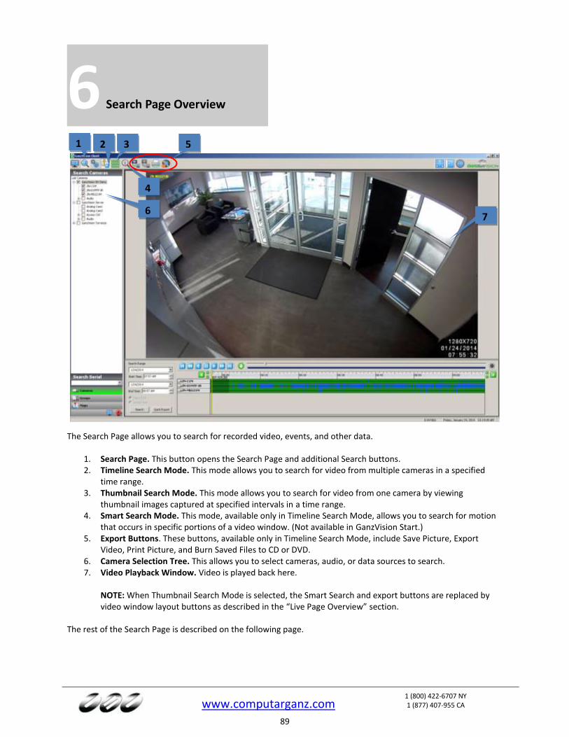
www.computarganz.com
1 (800) 422-6707 NY 1 (877) 407-955 CA
89
6 Search Page Overview
The Search Page allows you to search for recorded video, events, and other data.
1. Search Page. This button opens the Search Page and additional Search buttons. 2. Timeline Search Mode. This mode allows you to search for video from multiple cameras in a specified
time range. 3. Thumbnail Search Mode. This mode allows you to search for video from one camera by viewing
thumbnail images captured at specified intervals in a time range. 4. Smart Search Mode. This mode, available only in Timeline Search Mode, allows you to search for motion
that occurs in specific portions of a video window. (Not available in GanzVision Start.) 5. Export Buttons. These buttons, available only in Timeline Search Mode, include Save Picture, Export
Video, Print Picture, and Burn Saved Files to CD or DVD. 6. Camera Selection Tree. This allows you to select cameras, audio, or data sources to search. 7. Video Playback Window. Video is played back here.
NOTE: When Thumbnail Search Mode is selected, the Smart Search and export buttons are replaced by video window layout buttons as described in the “Live Page Overview” section.
The rest of the Search Page is described on the following page.
1 2
7
3
4
5
6
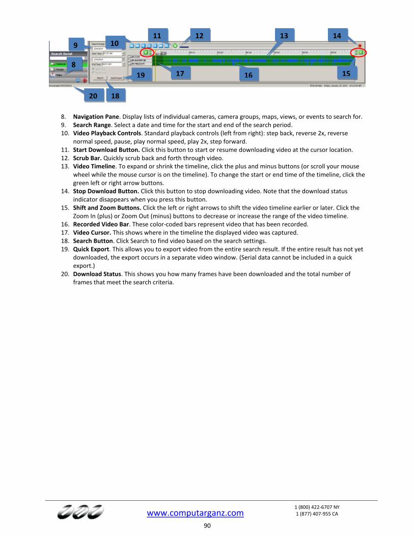
www.computarganz.com
1 (800) 422-6707 NY 1 (877) 407-955 CA
90
8. Navigation Pane. Display lists of individual cameras, camera groups, maps, views, or events to search for. 9. Search Range. Select a date and time for the start and end of the search period. 10. Video Playback Controls. Standard playback controls (left from right): step back, reverse 2x, reverse
normal speed, pause, play normal speed, play 2x, step forward. 11. Start Download Button. Click this button to start or resume downloading video at the cursor location. 12. Scrub Bar. Quickly scrub back and forth through video. 13. Video Timeline. To expand or shrink the timeline, click the plus and minus buttons (or scroll your mouse
wheel while the mouse cursor is on the timeline). To change the start or end time of the timeline, click the green left or right arrow buttons.
14. Stop Download Button. Click this button to stop downloading video. Note that the download status indicator disappears when you press this button.
15. Shift and Zoom Buttons. Click the left or right arrows to shift the video timeline earlier or later. Click the Zoom In (plus) or Zoom Out (minus) buttons to decrease or increase the range of the video timeline.
16. Recorded Video Bar. These color-coded bars represent video that has been recorded. 17. Video Cursor. This shows where in the timeline the displayed video was captured. 18. Search Button. Click Search to find video based on the search settings. 19. Quick Export. This allows you to export video from the entire search result. If the entire result has not yet
downloaded, the export occurs in a separate video window. (Serial data cannot be included in a quick export.)
20. Download Status. This shows you how many frames have been downloaded and the total number of frames that meet the search criteria.
8
9
18
13
16 17
10 12 14
19
11
15
20

www.computarganz.com
1 (800) 422-6707 NY 1 (877) 407-955 CA
91
Searching for Video and Other Data
Timeline Search Mode To perform a standard timeline search for video and other data, complete the following steps:
1. In the camera, group, map, or view tree, select one or more sources (cameras, audio inputs/outputs, POS, and so on). To search every source on an GanzVision server, check the box next to the server in the Camera Selection Tree (and then deselect any sources individually if desired). You can also select individual sources using the check boxes next to each camera.
2. Select the date and time you want to search. Click Search.
NOTE: If the client computer and a connected server are located in different time zones, the Client Time and Server Time options are also available. Search result listings are applicable to the selected time zone, and the time offset between the time zones is shown in parentheses.
3. When your search is complete, the camera names selected appear under the timeline with color-coded
recording bars representing recorded data. A color legend for the recorded video bars is located below the Search Range area; if you cannot see it, click the horizontal bar between the video window and the search results and drag it up.
NOTE: Alternatively, you can perform a quick search on the Live Page by right-clicking a video window, selecting Search from the pop-up menu, and selecting whether you want to search for video from the selected window or from all windows in the current layout. That procedure opens the Search Page with results from the last two hours from the selected camera or cameras.
1
2
3
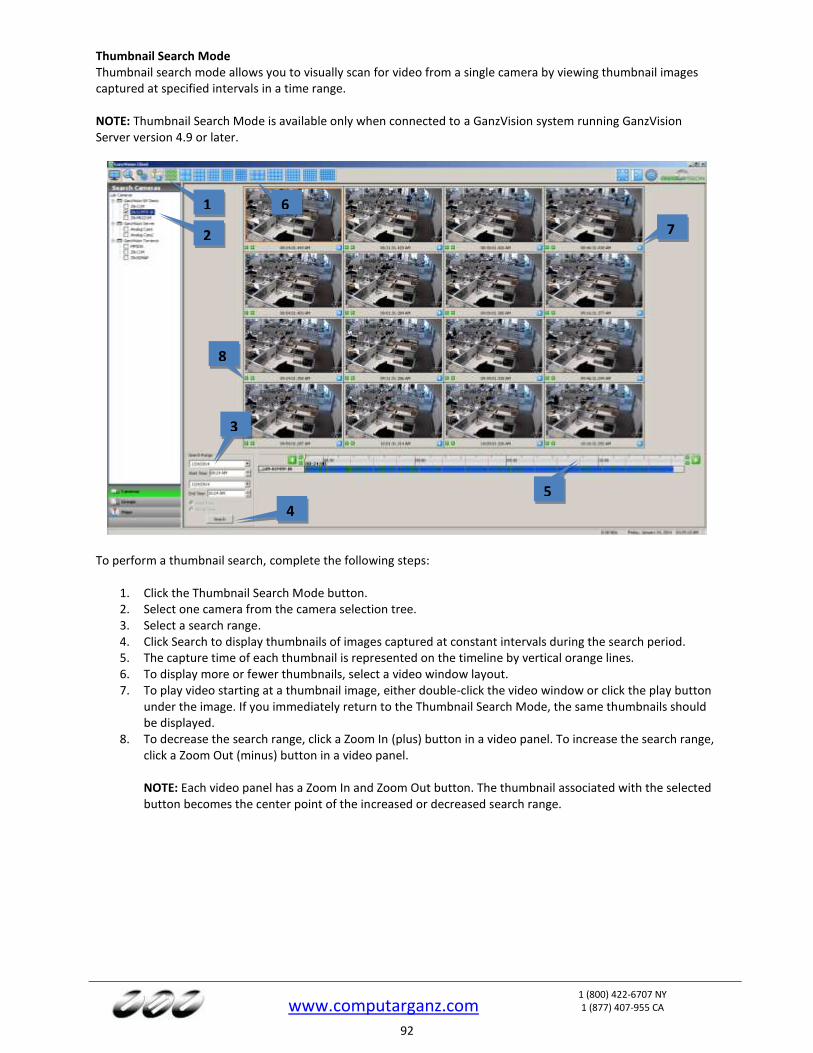
www.computarganz.com
1 (800) 422-6707 NY 1 (877) 407-955 CA
92
Thumbnail Search Mode Thumbnail search mode allows you to visually scan for video from a single camera by viewing thumbnail images captured at specified intervals in a time range. NOTE: Thumbnail Search Mode is available only when connected to a GanzVision system running GanzVision Server version 4.9 or later.
To perform a thumbnail search, complete the following steps:
1. Click the Thumbnail Search Mode button. 2. Select one camera from the camera selection tree. 3. Select a search range. 4. Click Search to display thumbnails of images captured at constant intervals during the search period. 5. The capture time of each thumbnail is represented on the timeline by vertical orange lines. 6. To display more or fewer thumbnails, select a video window layout. 7. To play video starting at a thumbnail image, either double-click the video window or click the play button
under the image. If you immediately return to the Thumbnail Search Mode, the same thumbnails should be displayed.
8. To decrease the search range, click a Zoom In (plus) button in a video panel. To increase the search range, click a Zoom Out (minus) button in a video panel. NOTE: Each video panel has a Zoom In and Zoom Out button. The thumbnail associated with the selected button becomes the center point of the increased or decreased search range.
1
2
3
4
5
6
7
8

www.computarganz.com
1 (800) 422-6707 NY 1 (877) 407-955 CA
93
Video Playback
To play back video, complete a search as described in the previous section and complete the following steps:
1. Select a camera for video playback by clicking on a camera name in the search results area. To select multiple cameras for playback, press and hold the Control key and then click each of the camera names. To select a range of consecutive cameras, press and hold the Shift key on the keyboard, click the first camera name in the range, and then click the final camera name in the range.
2. Click the play button to start displaying video at the beginning of the timeline. 3. To play video starting at another point on the timeline, double-click a recorded video bar in the
appropriate location under the timeline. Or, you can click once on the recorded video bar and then click the Play button.
4. To start or resume downloading video at the cursor location, click the Start Download button. 5. The green progress bar shows how much of the total video has been downloaded. The number of frames
downloaded and the total number of frames are also displayed in the status bar. 6. The area between the recorded video bars turn gray to show how much of each camera’s video has been
downloaded. To clear the downloaded video, right-click the timeline and select Clear Cache. You can clear the cache for the selected cameras or all cameras searched.
7. To stop video download, click the Stop button. All video downloaded before you pressed the Stop button can still be viewed.
8. To digitally zoom in on a single camera, double-click its video playback window. To return to the multi-camera view, double-click the remaining video playback window.
After the download has started, you can scrub back and forth through the video using the scrub bar and video playback controls. You can view only the portion of the video that has downloaded. You can quickly scan the video by dragging the slider to the left or right or by pressing Enter or Backspace on the keyboard. (Enter and Backspace plays every frame of video as quickly as the system hardware allows, unlike the normal Play and Reverse buttons, which play video at actual speed even if frames must be skipped to do so.)
1
2
3
5
6
7
8
4
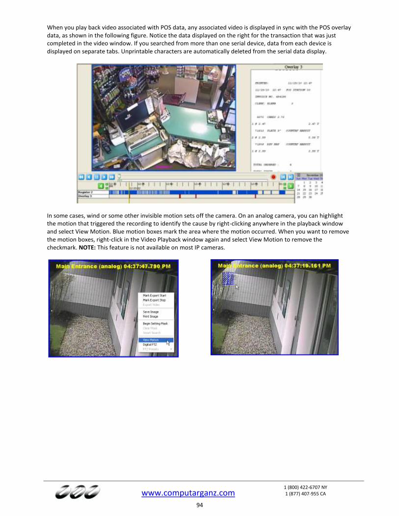
www.computarganz.com
1 (800) 422-6707 NY 1 (877) 407-955 CA
94
When you play back video associated with POS data, any associated video is displayed in sync with the POS overlay data, as shown in the following figure. Notice the data displayed on the right for the transaction that was just completed in the video window. If you searched from more than one serial device, data from each device is displayed on separate tabs. Unprintable characters are automatically deleted from the serial data display.
In some cases, wind or some other invisible motion sets off the camera. On an analog camera, you can highlight the motion that triggered the recording to identify the cause by right-clicking anywhere in the playback window and select View Motion. Blue motion boxes mark the area where the motion occurred. When you want to remove the motion boxes, right-click in the Video Playback window again and select View Motion to remove the checkmark. NOTE: This feature is not available on most IP cameras.
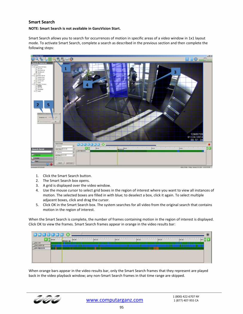
www.computarganz.com
1 (800) 422-6707 NY 1 (877) 407-955 CA
95
Smart Search
NOTE: Smart Search is not available in GanzVision Start. Smart Search allows you to search for occurrences of motion in specific areas of a video window in 1x1 layout mode. To activate Smart Search, complete a search as described in the previous section and then complete the following steps:
1. Click the Smart Search button. 2. The Smart Search box opens. 3. A grid is displayed over the video window. 4. Use the mouse cursor to select grid boxes in the region of interest where you want to view all instances of
motion. The selected boxes are filled in with blue; to deselect a box, click it again. To select multiple adjacent boxes, click and drag the cursor.
5. Click OK in the Smart Search box. The system searches for all video from the original search that contains motion in the region of interest.
When the Smart Search is complete, the number of frames containing motion in the region of interest is displayed. Click OK to view the frames. Smart Search frames appear in orange in the video results bar:
When orange bars appear in the video results bar, only the Smart Search frames that they represent are played back in the video playback window; any non-Smart Search frames in that time range are skipped.
1
2
3
4
5
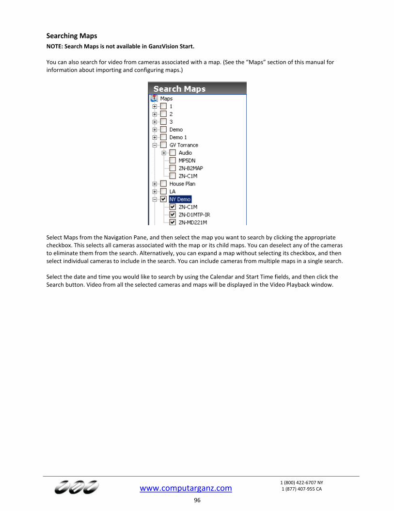
www.computarganz.com
1 (800) 422-6707 NY 1 (877) 407-955 CA
96
Searching Maps
NOTE: Search Maps is not available in GanzVision Start. You can also search for video from cameras associated with a map. (See the “Maps” section of this manual for information about importing and configuring maps.)
Select Maps from the Navigation Pane, and then select the map you want to search by clicking the appropriate checkbox. This selects all cameras associated with the map or its child maps. You can deselect any of the cameras to eliminate them from the search. Alternatively, you can expand a map without selecting its checkbox, and then select individual cameras to include in the search. You can include cameras from multiple maps in a single search. Select the date and time you would like to search by using the Calendar and Start Time fields, and then click the Search button. Video from all the selected cameras and maps will be displayed in the Video Playback window.
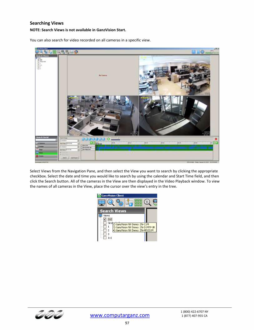
www.computarganz.com
1 (800) 422-6707 NY 1 (877) 407-955 CA
97
Searching Views
NOTE: Search Views is not available in GanzVision Start. You can also search for video recorded on all cameras in a specific view.
Select Views from the Navigation Pane, and then select the View you want to search by clicking the appropriate checkbox. Select the date and time you would like to search by using the calendar and Start Time field, and then click the Search button. All of the cameras in the View are then displayed in the Video Playback window. To view the names of all cameras in the View, place the cursor over the view’s entry in the tree.
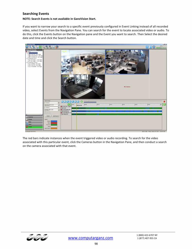
www.computarganz.com
1 (800) 422-6707 NY 1 (877) 407-955 CA
98
Searching Events
NOTE: Search Events is not available in GanzVision Start. If you want to narrow your search to a specific event previously configured in Event Linking instead of all recorded video, select Events from the Navigation Pane. You can search for the event to locate associated video or audio. To do this, click the Events button on the Navigation pane and the Event you want to search. Then Select the desired date and time and click the Search button.
The red bars indicate instances when the event triggered video or audio recording. To search for the video associated with this particular event, click the Cameras button in the Navigation Pane, and then conduct a search on the camera associated with that event.

www.computarganz.com
1 (800) 422-6707 NY 1 (877) 407-955 CA
99
Search Serial
The Search Serial drop-down list contains any key words associated with a profile configured on the Serial Profiles page. If the key word is linked to an event on the Event Linking page, you can search for the event using Search Serial. Following is an example of how Search Serial could be used:
1. Suppose you have a cash register connected to a GanzVision server, and you want to be able to search for video of all Bagels purchases at that register.
2. Use the Serial Profiles page to create a profile called Register 1. Also, add and enable a Key Word “Bagels.”
3. On the Event Linking page, create an Event with a type of Serial Profile or Serial Port. Select “Register 1 – Bagels” as the source, Record Video as the action, and the camera pointed at Register 1 as the target.
4. On the Serial Ports page, add the register as a POS device using the Register 1 profile. 5. On the Search Page, select the POS device from the tree and the associated camera. 6. Select “Bagels” from the Search Serial drop-down list.
7. Select the desired time range. 8. Click Search. All instances of “Bagels” that occurred in the POS data on the register during the time range
are shown on the timeline in red. The associated video is shown in blue. 9. You can now play back the video and associated POS data side-by-side.
NOTE: If you do not see the Search Serial drop-down list, make sure that you haven’t selected the Events button from the Navigation Pane.
www.computarganz.com
1 (800) 422-6707 NY 1 (877) 407-955 CA
100
Exporting Files
NOTE: For information about the Quick Export button, see the first list in “Search Page Overview.” The Export buttons allow you to save a picture or video, print a picture, or save files to a CD or DVD (including DVD+R and DVD+RW). Left to right, the icons are Save Picture, Save Video, Print Picture, and Burn Saved Files to CD or DVD:
NOTE: You can also copy a picture to a clip board and paste it into a document. When you find the image you need, right-click anywhere in the Video Playback window and select Copy Image to Clipboard. The image will be stored, and you can paste it into another document. To export video from up to 16 cameras or from a single camera on GanzVision Start, perform a video search and complete the following steps (note that serial data cannot be exported using this process):
1. Locate the start of the video clip. Right-click the timeline (or right-click the video window), select Export from the pop-up menu, and select Mark Export Start. A green line on the timeline indicates the Export Start location.
2. Locate the end of the video clip. Right-click the timeline (or right-click the video window), select Export from the pop-up menu, and select Mark Export Stop. See the illustrations below for examples. A red line on the timeline indicates the Export Stop location.
3. Right-click the timeline or video window, select Export from the pop-up menu, and select Download and Export Video. (You can clear the export start and stop markers by clicking Clear Export Markers from the same menu.)
4. In the Export Video window, select a file name and location. 5. Select a file type (as described below). 6. Click Save.
The export file defaults to a standalone *.exe file, which plays on its own and can be run by a Windows user who does not have access to a GanzVision Client. Alternatively, you can save the clip as a *.ps, *.avi, or *.mov file if you are emailing it to another GanzVision Client user; this will reduce the size of the clip. If the clips are intended for a computer running the Linux or Mac operating system, you should save the clip as a *.ps file unless you are emailing it to a Windows user.
NOTE: See the chart on the following page for information about file compatibility on each operating system. Also, an *.exe file can be created using any operating system even though it can be viewed using only Windows.
1
2=2
1=2 2
=2
3=2
3=2
4=2
5=2
6=2
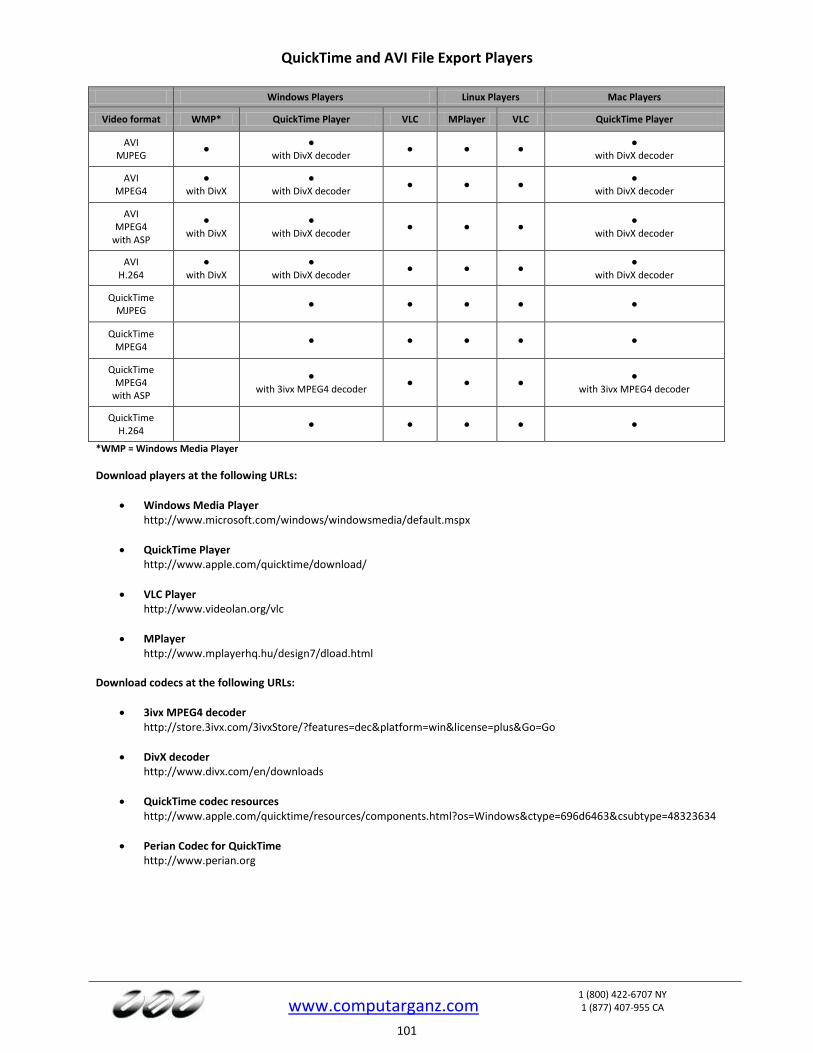
www.computarganz.com
1 (800) 422-6707 NY 1 (877) 407-955 CA
101
QuickTime and AVI File Export Players
Windows Players Linux Players Mac Players
Video format WMP* QuickTime Player VLC MPlayer VLC QuickTime Player
AVI MJPEG
● ●
with DivX decoder ● ● ●
● with DivX decoder
AVI MPEG4
● with DivX
● with DivX decoder
● ● ● ●
with DivX decoder
AVI MPEG4
with ASP
● with DivX
● with DivX decoder
● ● ● ●
with DivX decoder
AVI H.264
● with DivX
● with DivX decoder
● ● ● ●
with DivX decoder
QuickTime MJPEG
● ● ● ● ●
QuickTime MPEG4
● ● ● ● ●
QuickTime MPEG4
with ASP
● with 3ivx MPEG4 decoder
● ● ● ●
with 3ivx MPEG4 decoder
QuickTime H.264
● ● ● ● ●
*WMP = Windows Media Player
Download players at the following URLs:
Windows Media Player http://www.microsoft.com/windows/windowsmedia/default.mspx
QuickTime Player http://www.apple.com/quicktime/download/
VLC Player http://www.videolan.org/vlc
MPlayer http://www.mplayerhq.hu/design7/dload.html
Download codecs at the following URLs:
3ivx MPEG4 decoder http://store.3ivx.com/3ivxStore/?features=dec&platform=win&license=plus&Go=Go
DivX decoder http://www.divx.com/en/downloads
QuickTime codec resources http://www.apple.com/quicktime/resources/components.html?os=Windows&ctype=696d6463&csubtype=48323634
Perian Codec for QuickTime http://www.perian.org
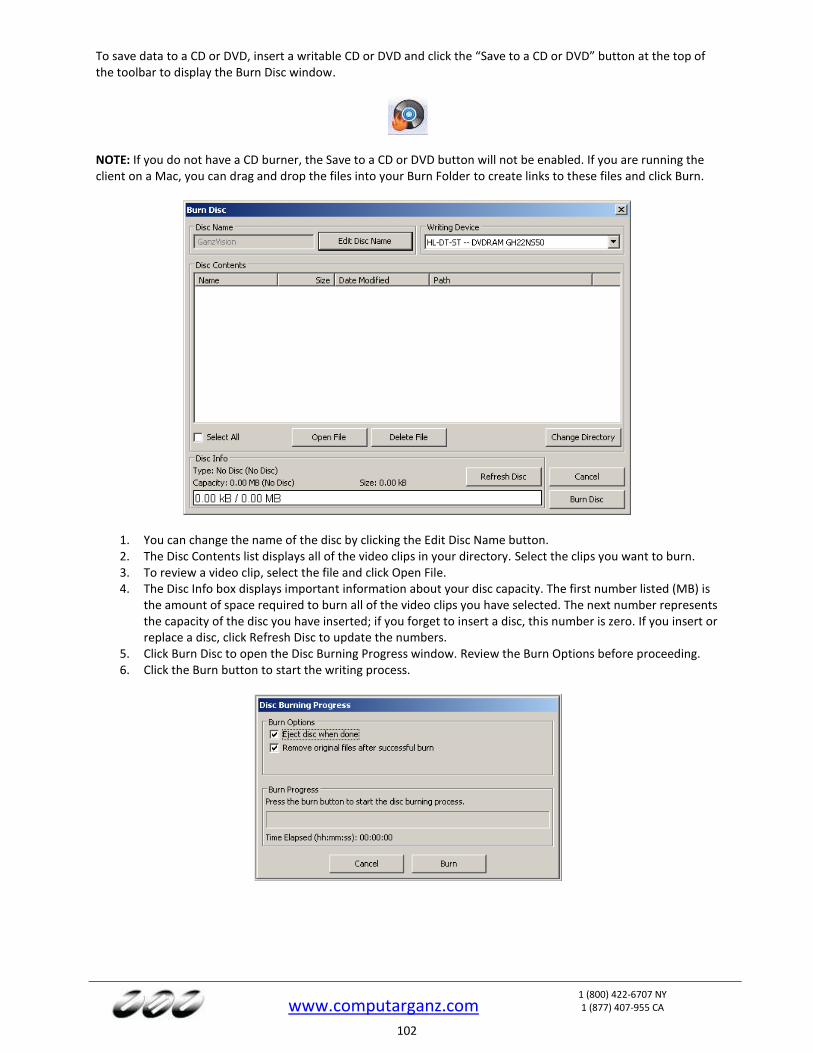
www.computarganz.com
1 (800) 422-6707 NY 1 (877) 407-955 CA
102
To save data to a CD or DVD, insert a writable CD or DVD and click the “Save to a CD or DVD” button at the top of the toolbar to display the Burn Disc window.
NOTE: If you do not have a CD burner, the Save to a CD or DVD button will not be enabled. If you are running the client on a Mac, you can drag and drop the files into your Burn Folder to create links to these files and click Burn.
1. You can change the name of the disc by clicking the Edit Disc Name button. 2. The Disc Contents list displays all of the video clips in your directory. Select the clips you want to burn. 3. To review a video clip, select the file and click Open File. 4. The Disc Info box displays important information about your disc capacity. The first number listed (MB) is
the amount of space required to burn all of the video clips you have selected. The next number represents the capacity of the disc you have inserted; if you forget to insert a disc, this number is zero. If you insert or replace a disc, click Refresh Disc to update the numbers.
5. Click Burn Disc to open the Disc Burning Progress window. Review the Burn Options before proceeding. 6. Click the Burn button to start the writing process.
www.computarganz.com
1 (800) 422-6707 NY 1 (877) 407-955 CA
103
A Technical Support
CBC (America) Corp. is committed to providing exceptional technical and engineering support. When you need
help with your GanzVision product, please be ready with a complete description of the problem, including any
error messages or instructions on re-creating the error.
Technical support can be contacted as follows:
CBC (America) Corp
55 Mall Drive
Commack, NY 11725 USA
Phone: NY +1-800-422-6707
CA +1-887-407-9555
E-mail: [email protected]
Web: http://www.Computarganz.com
www.computarganz.com
1 (800) 422-6707 NY 1 (877) 407-955 CA
104
B Regulatory Notice
Federal Communications Commission (FCC) Radio Frequency Interference Statement
The CBC (America) Corp Product contains incidental radio frequency-generating circuitry and, if not installed and used properly, may cause interference to radio and television reception. This equipment has been tested and found to comply with the limits for a Class A computing device pursuant to Subpart J of Part 15 of the Federal Communications Commission (FCC) Rules. These limits are designed to provide reasonable protection against such interference when operated in a commercial environment. Operation of this equipment in a residential area may cause interference to radio and television reception, in which case users will be required to correct the interference at their own expense. If this equipment does cause interference to radio or television reception, which can be determined by turning the equipment off and on, users are encouraged to try to correct the interference by one or more of the following measures: Reorient the television or radio receiving antenna, and/or relocate the CBC (America) Corp product and the radio or TV with respect to each other. If necessary, users should consult the manufacturer or an experienced radio/television technician for additional suggestions. Users may find helpful the following booklet prepared by the Federal Communications Commission: “How to Identify and Resolve Radio-TV Interference Problems,” which is available from the Government Printing Office, Washington DC, 20402 (stock #004-000-00345-4).
CE Notice
Marking by the symbol indicates compliance of this device to the EMC directive of the European Community. Such marking is indicative that this device meets or exceeds the following technical standards:
- EN55022: Conducted Emissions - EN55022: Radiated Emissions - 61000-4-2 Electrostatic Discharge - 61000-4-3 Radiated Immunity - 61000-4-4 Electrical Fast Transients - 61000-4-5 Surge Immunity - 61000-4-6 Conducted Immunity
Electromagnetic compatibility (EMC) requires the use of shielded cable and ferrite cores for all wiring added by the user. Good shielding techniques should be applied in the user’s system.

www.computarganz.com
1 (800) 422-6707 NY 1 (877) 407-955 CA
105
C Warranty
LIMITED WARRANTY AND LIMITATION OF LIABILITY LIMITED WARRANTY. CBC (America) Corp hardware products are warranted against defects in materials and workmanship for three (3) years from the date CBC (America) Corp ships the products to the Customer. All software products are licensed to the Customer under the terms of the appropriate CBC (America) Corp Technologies license. For a period of ninety (90) days from the Delivery Date, CBC (America) Corp software products (when properly installed on CBC (America) Corp hardware products) (a) will perform substantially in accordance with the accompanying written materials, and (b) the medium on which the software product is recorded will be free from defects in materials and workmanship under normal use and service. Any replacement of a licensed software product will be warranted for the remainder of the original warranty period or thirty (30) days, whichever is longer. Customer must obtain a Return Material Authorization number from CBC (America) Corp before returning any products under warranty to CBC (America) Corp. Customer shall pay expenses for shipment of repaired or replacement products to and from CBC (America) Corp. After examining and testing a returned product, if CBC (America) Corp concludes that a returned product is not defective, Customer will be notified, the product returned at Customer’s expense, and a charge made for examination and testing. This Limited Warranty is void if products or parts are damaged by (a) improper handling, normal wear and tear, accidents, theft, vandalism, fire, water or other peril; (b) conditions outside the specifications for operation of the products, including but not limited to, electrical power, temperature humidity, dust or lightning; (c) Customer supplied third party software not intended for use with the applicable CBC (America) Corp software; (d) utilization of an improper hardware or software key; (e) or improper use, negligence, repair, alteration or maintenance of the product not performed by CBC (America) Corp Technologies, Inc. or its authorized service centers or authorized technicians. CUSTOMER REMEDIES. CBC (America) Corp’s sole obligation (and Customer’s sole remedy) with respect to the foregoing Limited Warranty shall be to, at its option, return the fees paid or repair/replace any defective products, provided that CBC (America) Corp receives written notice of such defects during the applicable warranty period. Customer may not bring an action to enforce its remedies under the foregoing Limited Warranty more than one (1) year after the accrual of such cause of action. RETURN/CANCELLATION POLICY. Customer may return unwanted products within thirty (30) days of the Delivery Date. Customer shall pay a twenty percent (20%) restocking charge on any unwanted products returned to CBC (America) Corp. No returns will be accepted after the thirty (30) day period has expired. Where special equipment or services are involved, Customer shall be responsible for all related work in progress; however, CBC (America) Corp shall take responsible steps to mitigate damages immediately upon receipt of a written cancellation notice from Customer. A Return Material Authorization number must be obtained from CBC (America) Corp for return of any products. CBC (America) Corp may terminate any order if any representations made by Customer to CBC (America) Corp are false or misleading. NO OTHER WARRANTIES. EXCEPT AS EXPRESSLY SET FORTH ABOVE, THE PRODUCTS ARE PROVIDED “AS IS” WITHOUT WARRANTY OF ANY KIND, AND NO OTHER WARRANTIES, EITHER EXPRESSED OR IMPLIED ARE MADE WITH RESPECT TO THE PRODUCTS, INCLUDING BUT NOT LIMITED TO ANY IMPLIED WARRANTIES OF MERCHANTABILITY, FITNESS FOR A PARTICULAR PURPOSE, TITLE OR NON-INFRINGEMENT OR ANY OTHER WARRANTIES THAT MAY ARISE FROM USAGE OF TRADE OR COURSE OF DEALING. CBC (AMERICA) CORP DOES NOT WARRANT, GUARANTEE, OR MAKE ANY REPRESENTATIONS REGARDING THE USE OF OR THE RESULTS OF THE USE OF THE PRODUCTS IN TERMS OF CORRECTNESS ACCURACY RELIABILITY OR OTHERWISE AND DOES NOT WARRANT THAT THE OPERATION OF THE PRODUCTS WILL BE UNINTERRUPTED OR ERROR FREE. CBC (AMERICA) CORP EXPRESSLY DISCLAIMS ANY WARRANTIES NOT STATED HEREIN. NO LIABILITY FOR CONSEQUENTIAL DAMAGES. The entire liability of CBC (America) Corp and its licensors, distributors and suppliers (including its and their directors, officers, employees and agents) is set forth above. To the maximum extent permitted by applicable law, in no event shall CBC (America) Corp and its licensors, distributors and suppliers (including its and their directors, officers, employees and agents) be liable for any damages including but not limited to any special, direct, indirect, incidental, exemplary, or consequential damages, expenses, lost profits, lost savings, business interruption, lost business information, or any other damages arising out of the use or inability to use the products, even if CBC (America) Corp or its licensors, distributors, and suppliers has been advised of the possibility of such damages. Customer acknowledges that the applicable purchase price or license fee for the products reflects this allocation of risk. Because some states/jurisdictions do not allow the exclusion or limitation of liability for consequential or incidental damages, the above limitation may not apply. If the foregoing limitation of liability is not enforceable because an CBC (America) Corp product sold or licensed to Customer is determined by a court of competent jurisdiction in a final non appeal able judgment to be defective and to have directly caused bodily injury death or property damage in no event shall CBC (America) Corp’s liability for property damage exceed the greater of $50,000 or fees paid for the specific product that caused such damage WARNING: IN ANY APPLICATION THE RELIABILITY OF OPERATION OF THE PRODUCTS CAN BE IMPAIRED BY ADVERSE FACTORS, INCLUDING BUT NOT LIMITED TO FLUCTUATIONS IN ELECTRICAL POWER SUPPLY, COMPUTER HARDWARE MALFUNCTIONS, COMPUTER OPERATING SYSTEM SOFTWARE FITNESS, FITNESS OF COMPILERS AND DEVELOPMENT SOFTWARE USED TO DEVELOP AN APPLICATION, INSTALLATION ERRORS, SOFTWARE AND HARDWARE COMPATIBILITY PROBLEMS, MALFUNCTIONS OR FAILURES OF ELECTRONIC MONITORING OR CONTROL DEVICES, TRANSIENT FAILURES OF ELECTRONIC SYSTEMS (HARDWARE AND/OR SOFTWARE), UNANTICIPATED USES OR MISUSES, OR ERRORS ON THE PART OF THE USER OR APPLICATIONS DESIGNER (ADVERSE FACTORS SUCH AS THESE ARE HEREAFTER COLLECTIVELY TERMED “SYSTEM FAILURES”). ANY APPLICATION WHERE A SYSTEM FAILURE WOULD CREATE A RISK OF HARM TO PROPERTY OR PERSONS (INCLUDING THE RISK OF BODILY INJURY AND DEATH) SHOULD NOT BE RELIANT SOLELY UPON ONE FORM OF ELECTRONIC SYSTEM DUE TO THE RISK OF SYSTEM FAILURE. TO AVOID DAMAGE, INJURY, OR DEATH, THE USER OR APPLICATION DESIGNER MUST TAKE REASONABLY PRUDENT STEPS TO PROTECT AGAINST SYSTEM FAILURES, INCLUDING BUT NOT LIMITED TO BACK-UP OR SHUT DOWN MECHANISMS. BECAUSE EACH END-USER SYSTEM IS CUSTOMIZED AND DIFFERS FROM CBC (America) Corp’S TESTING PLATFORMS AND BECAUSE A USER OR APPLICATION DESIGNER MAY USE CBC (America) Corp PRODUCTS IN COMBINATION WITH OTHER PRODUCTS IN A MANNER NOT EVALUATED OR CONTEMPLATED BY CBC (America) Corp THE USER OR APPLICATION DESIGNER IS ULTIMATELY RESPONSIBLE FOR VERIFYING AND VALIDATING THE SUITABILITY OF CBC (America) Corp PRODUCTS WHENEVER CBC (America) Corp PRODUCTS ARE INCORPORATED IN A SYSTEM OR APPLICATION, INCLUDING, WITHOUT LIMITATION, THE APPROPRIATE DESIGN, PROCESS AND SAFETY LEVEL OF SUCH SYSTEM OR APPLICATION.
www.computarganz.com
1 (800) 422-6707 NY 1 (877) 407-955 CA
106
D Manual Updates
Following are manual updates since the most recent major revision of the GanzVision Client software:
Release 4.9
Updated Storage Setup section to include tabbed layout and hardware monitoring features.
Updated Notifications section with procedure for sending text messages.
Updated Event Monitoring section to include new profile types and action targets
Updated Client Setup section with modified VGA Acceleration Mode options and Use 24-Hour Clock (Mac version) option.
Updated Map Setup and Live Maps sections to include soft trigger activation.
Updated PTZ Control section to include a discussion about command priorities.
Updated Camera Views section to include My Event Monitors.
Updated Search Mode Overview and Video Playback sections with thumbnail feature and Start Download button.
Release 4.11
Updated Event Linking section to include Time Trigger event type.
Updated Joystick section to include new interface and features.
Updated Ganz-Replay section to include export of full layout.
Updated Search Page Overview section to include Quick Export feature.
Updated Searching for Video and Other Data section to include note about quick search from Live Page.
New screenshots throughout to show updated icons.
Updated GanzVision page names.
Release 5.4
Changed Ganz-Recall to Auto Export and added new feature description.
Added multistreaming feature to Camera Settings and Add Systems sections.
Added Clear Cache option to Video Playback section.
Updated Layout Panel section with modified Find Camera feature.
Updated PTZ Configuration and PTZ Control sections with merged PTZ and preset windows.
Updated System section with the Watchdog Timer tab.
Added Views and Tours sections.
Updated Maps and Groups sections to include new layout.
Updated PTZ sections for clarity.
Updated Add IP Cameras section to include new layout.
Updated Add Systems section to include new layout and Import/Export buttons.
Updated Enterprise Users section to include new Export button.
Updated System section to include modified System tab and new Hardware Monitoring tab.
Updated System section to include Update tab.
Updated IP Camera Recording and Analog Camera Recording pages to include new layout.
Update Serial Profile and Serial Port pages to include new layout and columns.
Added Search Archive page.
Updated Client page to include audio/video synchronization option.
www.computarganz.com
1 (800) 422-6707 NY 1 (877) 407-955 CA
107
Release 5.6
Updated Notifications section to include new layout and Attach Preview feature.
Updated Schedule section to include new layout.
Changed Search Archive page to Archive and documented expanded functionality.
Added deblocking feature to Client section.
Added Layouts section.
Release 5.10
Added Source Groups to the Event Linking section.
Added International Character Support and Send Usage Statistics to the System section.
Clarified information in the Notifications section.
Added 2-Way Audio section.
Added 2-way audio features to Audio Inputs and Client sections.
Modified Storage section to include Extended and Network tabs.
Added Enterprise Storage section.
Modified Add Systems page to include central server database location feature.
Modified Notifications section to include new supported tags.