european technical approval eta-13/0029 - wuerth...page 3 of 17 of european technical approval no....
TRANSCRIPT
ETA-Danmark A/S Kollegievej 6 DK-2920 Charlottenlund Tel. +45 72 24 59 00 Fax +45 72 24 59 04 Internet www.etadanmark.dk
MEMBER OF EOTA
Authorised and notified according to Article 10 of the Council Directive 89/106/EEC of 21 December 1988 on the approximation of laws, regulations and administrative provisions of Member States relating to construction products
European Technical Approval ETA-13/0029
This ETA replaces the previous ETA with the same number and validity from 2013-01-09 to 2017-07-16 Trade name:
Würth self-tapping screw
Holder of approval: Adolf Würth GmbH & Co. KG Reinhold Würth Strasse 12 – 17 D-74650 Künzelsau Tel. +49 7940 15 0 Fax +49 7940 15 1000 Internet www.wuerth.com
Generic type and use of con-struction product:
Self-tapping screws for use in wood-concrete slab kits
Valid from: to:
2013-01-29 2017-07-16
Manufacturing plant: Werk I, Werk II, Werk III
This European Technical Approval contains:
17 pages including 3 annexes which form an integral part of the document
Page 2 of 17 of European Technical Approval no. ETA-13/0029
I LEGAL BASIS AND GENERAL CONDITIONS
1 This European Technical Approval is issued by
ETA-Danmark A/S in accordance with: - Council Directive 89/106/EEC of 21 December
1988 on the approximation of laws, regulations and administrative provisions of Member States relating to construction products1), as amended by Council Directive 93/68/EEC of 22 July 19932).
- Bekendtgørelse 559 af 27-06-1994 (afløser
bekendtgørelse 480 af 25-06-1991) om ikrafttræ-den af EF direktiv af 21. december 1988 om indbyrdes tilnærmelse af medlemsstaternes love og administrative bestemmelser om byggevarer.
- Common Procedural Rules for Requesting,
Preparing and the Granting of European Techni-cal Approvals set out in the Annex to Commis-sion Decision 94/23/EC3).
2 ETA-Danmark A/S is authorized to check whet-
her the provisions of this European Technical Approval are met. Checking may take place in the manufacturing plant. Nevertheless, the responsi-bility for the conformity of the products to the European Technical Approval and for their fitness for the intended use remains with the holder of the European Technical Approval.
3 This European Technical Approval is not to be
transferred to manufacturers or agents of manu-facturers other than those indicated on page 1, or manufacturing plants other than those indicated on page 1 of this European Technical Approval.
4 This European Technical Approval may be
withdrawn by ETA-Danmark A/S pursuant to Article 5(1) of Council Directive89/106/EEC.
5 Reproduction of this European Technical Approval including transmission by electronic means shall be in full. However, partial reproduction can be made with the written consent of ETA-Danmark A/S. In this case partial reproduction has to be designated as such. Texts and drawings of advertising brochures shall not contradict or misuse the European Technical Approval.
6 This European Technical Approval is issued by ETA-
Danmark A/S in English. This version corresponds fully to the version circula-
ted within EOTA. Translations into other languages have to be designated as such.
1) Official Journal of the European Communities No L40, 11 Feb 1989, p 12. 2) Official Journal of the European Communities No L220, 30 Aug 1993, p 1. 3) Official Journal of the European Communities No L 17, 20 Jan 1994, p 34.

Page 3 of 17 of European Technical Approval no. ETA-13/0029
II SPECIAL CONDITIONS OF THE EUROPEAN TECHNICAL APPROVAL
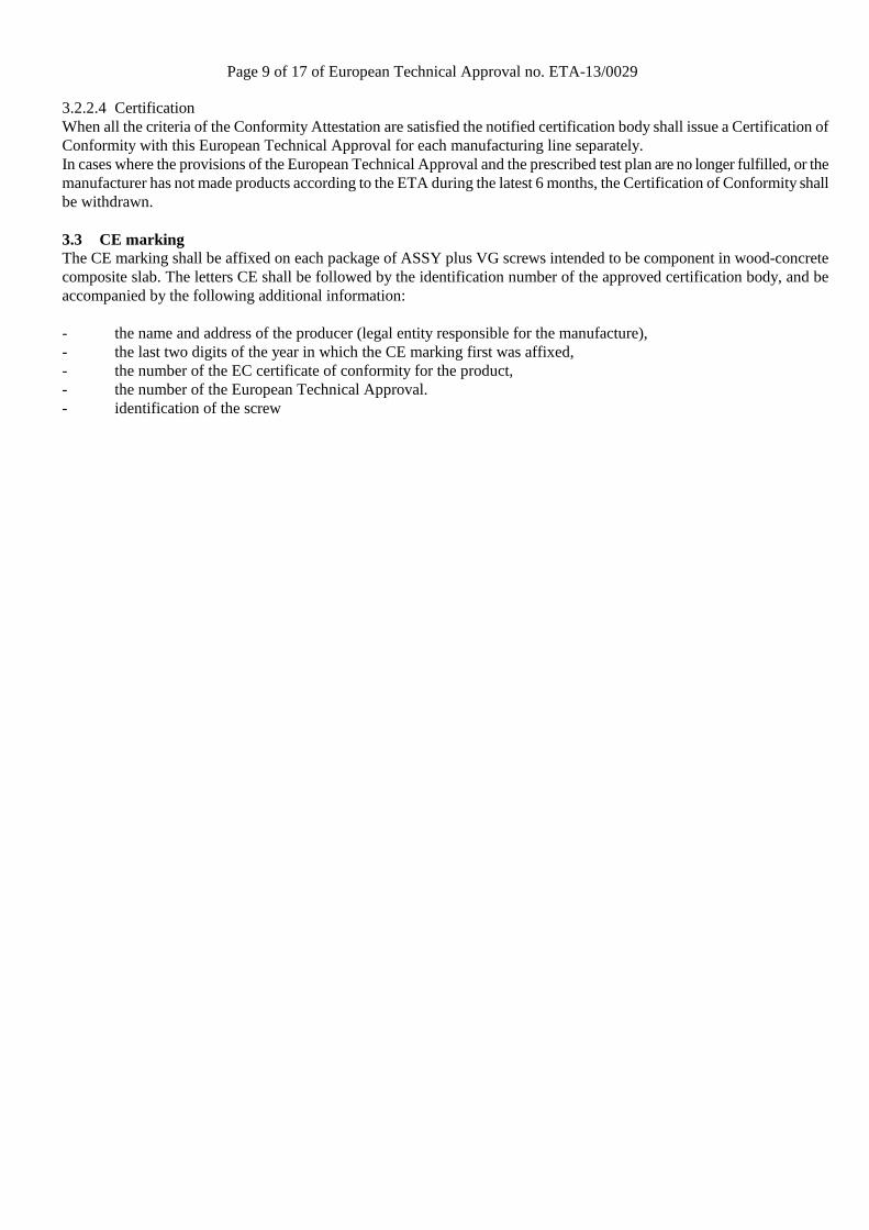
1 Definition of product and intended use This ETA is an assessment of the ASSY plus VG screw for wood-concrete composite slab kits. The assessment concerns use of the screws in composite slab kits, however, the approval holder only delivers the screws. The diameter of the ASSY plus VG screws is either 8 mm or 10 mm, the length ranges between 150 mm and 800 mm. The shape and tolerances of the screws are given in Annex 3. ASSY plus VG screws with 10 mm diameter arranged under 30° between screw axis and joint line are always used together with FT-connectors. NOTE. The FT-connector has not been assessed in its own right, but the assessments forming the basis for this ETA presumes that the FT-connector is used and the characteristic capacities indicated in the ETA are valid only if the ASSY plus VG screw is used together with the FT-connector. The kits are individually designed to meet the requirements put on the works. Adolf Würth GmbH & Co. KG delivers the ASSY plus VG screws and, where applicable, the FT-connectors, for the composite action to be used as kit components. The composite members may be prefabricated at factory, or they may be composed at the building site. The proper function of the wood-concrete composite slabs provides for the following components to be added in the factory or at the building site: - Concrete slab, according to EN 1992-1-1, and national regulations either prefabricated or cast at the building site.
The minimum concrete strength class is C20/25.
- In the case of concrete cast at the building site: formwork, e.g. timber boards or wood based panel. This is an optional intermediate layer between the concrete and the timber.
- In the case of concrete cast at the building site: lateral moulding along the edges of the slab.
- Timber members, e.g. glulam according to EN 14080, sawn softwood timber according to EN 14081-1, LVL according to EN 14374 or cross laminated timber according to ETA.
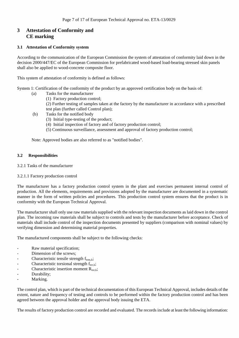
The concrete flange is loaded in compression. The timber members are usually parallel or almost parallel. This ETA covers screws for composite members with minimum concrete flange depths which comply with the regulations on the slab depths in the place use (national regulations) but not less than 50 mm for 8 mm screws and 70 mm for 10 mm screws, and minimum timber member depths of 100 mm. The maximum concrete flange depth is 70 % of the timber member depth. Typical spans for the construction are up to 8 m with sawn softwood timber members, 10 m with LVL members and 14 m with glulam members but larger spans also are possible. A typical composite member is shown in figure 1.1a of Annex 1. A typical screw is shown in figure 1.1d.
Intended use ASSY plus VG screws are intended to be used in structural composite members such as floor, roof, or wall constructions in service classes 1 and 2 as defined in EN 1995-1-1 subject to static or quasi static loading. In addition, use class 3.1 as defined in EN 335-1 (exterior, above ground, protected) may be possible, as balconies depending on national provisions. With regard to ER3, health and environment, the following use categories are relevant: - Category A2: Products with no direct contact with indoor air but possible impact on indoor air:
These products are either covered (e.g. by other products) but could be released into the indoor air due to diffusion or have to be considered in the case of maintenance and repair.
- Category B3: Products with no contact with soil and/or water: These products are either covered (e.g. by other products) but could never be released into soil and/or water due to diffusion
Assumed working life The provisions made in this European Technical Approval are based on an assumed working life of ASSY plus VG screw for wood-concrete composite floors of 50 years, provided that the conditions laid down in this ETA for the installation, use and maintenance are met.
Page 4 of 17 of European Technical Approval no. ETA-13/0029
The indications given on the working life cannot be interpreted as a guarantee given by the producer or the approval body, but are to be regarded only as a means for choosing the right products in relation to the expected economically reasonable working life of the works.

Page 5 of 17 of European Technical Approval no. ETA-13/0029
2 Characteristics of product and assessment 2.1 ER 1 Mechanical resistance and stability 2.1.1 Structural performance
Wood-concrete composite slabs including ASSY plus VG screws are used and manufactured according to an individual design made by a structural engineer responsible for the design of works on a case by case basis. Wood-concrete composite floors may function as directly load bearing and structural bracing members. The structural performance of them shall be considered in accordance with the limit state design principles specified in Eurocodes. The performance of the composite slab is outside of this ETA. The screws are made of case hardened steel as specified in the control plan and corrosion protected with a zinc coating. Geometry of the screws is defined in Annex 3. Mechanical properties of ASSY plus VG screws and applicable creep and duration of load factors for composite members are given in Annex 2.
2.2 ER 2 Safety in case of fire 2.2.1 Reaction to fire
ASSY plus VG screws including the zinc coating are classified non-combustible in accordance with EC Decision 2000/147/EC and fulfil the requirements of class A1 according to EN 13501-1: 2002.
2.2.2 Resistance to fire
No performance determined. 2.3 ER 3 Hygiene, health and environment 2.3.1 Dangerous substances
Based on the declaration of the manufacturer, ASSY plus VG screws do not contain harmful or dangerous substances as defined in the EU database. On site added materials and components of the kits shall be checked against dangerous substances as specified by the CE-marking of those products.
In addition to the specific clauses relating to dangerous substances contained in this European Technical Approval, there may be other requirements applicable to the products falling within its scope (e.g. transposed European legislation and national laws, regulations and administrative provisions). In order to meet the provisions of the Construction Products Directive, these requirements need also to be complied with, when and where they apply.
2.3.2 Water vapour permeability and moisture resistance
Not relevant.
2.4 ER 4 Safety in use
Not relevant. 2.5 ER 5 Protection against noise 2.5.1 Airborne sound insulation
Not relevant. 2.5.2 Impact sound insulation
Not relevant. 2.5.3 Sound absorption
Not relevant.
Page 6 of 17 of European Technical Approval no. ETA-13/0029
2.6 ER 6 Energy economy and heat retention 2.6.1 Thermal resistance
Not relevant. 2.6.2 Air permeability
Not relevant. 2.6.3 Thermal inertia
Not relevant. 2.7 Aspects of durability, serviceability and identification 2.7.1 Durability
Durability of the finished composite slab is not covered by this ETA.
Durability of the ASSY plus VG screws is provided for by the protective zinc coating for a mean thickness of 5 µm. 2.7.2 Serviceability
Deformation characteristics for the ASSY plus VG screw are given in Annex 2. 2.7.3 Identification
ASSY plus VG screws are identified by bearing the mark of the manufacturer and the CE mark as described in clause 4.
Page 7 of 17 of European Technical Approval no. ETA-13/0029
3 Attestation of Conformity and CE marking
3.1 Attestation of Conformity system According to the communication of the European Commission the system of attestation of conformity laid down in the decision 2000/447/EC of the European Commission for prefabricated wood-based load-bearing stressed skin panels shall also be applied to wood-concrete composite floor. This system of attestation of conformity is defined as follows: System 1: Certification of the conformity of the product by an approved certification body on the basis of:
(a) Tasks for the manufacturer (1) Factory production control; (2) Further testing of samples taken at the factory by the manufacturer in accordance with a prescribed test plan (further called Control plan);
(b) Tasks for the notified body (3) Initial type-testing of the product; (4) Initial inspection of factory and of factory production control; (5) Continuous surveillance, assessment and approval of factory production control;
Note: Approved bodies are also referred to as "notified bodies".
3.2 Responsibilities 3.2.1 Tasks of the manufacturer 3.2.1.1 Factory production control The manufacturer has a factory production control system in the plant and exercises permanent internal control of production. All the elements, requirements and provisions adopted by the manufacturer are documented in a systematic manner in the form of written policies and procedures. This production control system ensures that the product is in conformity with the European Technical Approval. The manufacturer shall only use raw materials supplied with the relevant inspection documents as laid down in the control plan. The incoming raw materials shall be subject to controls and tests by the manufacturer before acceptance. Check of materials shall include control of the inspection documents presented by suppliers (comparison with nominal values) by verifying dimension and determining material properties. The manufactured components shall be subject to the following checks: - Raw material specification; - Dimension of the screws; - Characteristic tensile strength ftens,k; - Characteristic torsional strength ftor,k; - Characteristic insertion moment Rtor,k; - Durability; - Marking. The control plan, which is part of the technical documentation of this European Technical Approval, includes details of the extent, nature and frequency of testing and controls to be performed within the factory production control and has been agreed between the approval holder and the approval body issuing the ETA. The results of factory production control are recorded and evaluated. The records include at least the following information:
Page 8 of 17 of European Technical Approval no. ETA-13/0029
- Designation of the product, basic material and components; - Type of control or testing; - Date of manufacture of the product and date of testing of the product or basic material and components; - Result of control and testing and, if appropriate, comparison with requirements; - Signature of person responsible for factory production control. The records shall be presented to the approval body issuing the ETA on request. The records shall be presented to ETA-Danmark on request.
Other tasks of the manufacturer The manufacturer shall, on the basis of a contract, involve a body which is approved for the tasks referred to in section 3.1 in the field of screws for wood-concrete composite floors in order to undertake the actions laid down in section 3.3. For this purpose, the control plan referred to in sections 3.1 and 3.2.2 shall be handed over by the manufacturer to the notified body involved. The manufacturer shall make a declaration of conformity, stating that the construction product is in conformity with the provisions of the European Technical Approval. 3.2.2. Tasks of notified bodies The notified body (bodies) shall perform the - initial type testing of the product, - initial inspection of factory and of factory production control, - continuous surveillance, assessment and approval of factory production control, in accordance with the provisions laid down in the control plan. The notified body shall retain the essential points of its actions referred to above and state the results obtained and conclusions drawn in written reports. The notified certification body involved by the manufacturer shall issue an EC certificate of conformity of the product stating the conformity with the provisions of this European Technical Approval. In cases where the provisions of the European Technical Approval and its control plan are no longer fulfilled the certification body shall withdraw the certificate of conformity and inform ETA-Danmark without delay. 3.2.2.1 Initial type testing of the product Approval tests have been conducted under responsibility of ETA-Danmark. ETA-Danmark has assessed the results of these tests, as part of the ETA issuing procedure. The product characteristics determined by the initial test programme and by the experience of the external inspections is found sufficient to serve as initial type testing. This shall be validated by the notified body for the purpose of certification of conformity. 3.2.2.2 Initial inspection of the factory and the factory production control A notified body shall conduct initial inspection of each manufacturing line in order to ensure that the premises and technical equipment are acceptable, personnel is qualified and a factory production control system which is in accordance with the provisions in this ETA is followed. 3.2.2.3 Continuous surveillance, assessment and approval of the factory production control The notified body shall visit the factory at least once a year for regular inspection. It shall be verified that the factory production control is performed according to this ETA, including tests of samples according to the prescribed test plan.
Page 9 of 17 of European Technical Approval no. ETA-13/0029
3.2.2.4 Certification When all the criteria of the Conformity Attestation are satisfied the notified certification body shall issue a Certification of Conformity with this European Technical Approval for each manufacturing line separately. In cases where the provisions of the European Technical Approval and the prescribed test plan are no longer fulfilled, or the manufacturer has not made products according to the ETA during the latest 6 months, the Certification of Conformity shall be withdrawn. 3.3 CE marking The CE marking shall be affixed on each package of ASSY plus VG screws intended to be component in wood-concrete composite slab. The letters CE shall be followed by the identification number of the approved certification body, and be accompanied by the following additional information: - the name and address of the producer (legal entity responsible for the manufacture), - the last two digits of the year in which the CE marking first was affixed, - the number of the EC certificate of conformity for the product, - the number of the European Technical Approval. - identification of the screw

Page 10 of 17 of European Technical Approval no. ETA-13/0029
4 Assumptions under which the fitness of the product for the intended use was favourably assessed 4.1 Manufacturing Adolf Würth GmbH & Co. KG delivers ASSY plus VG screws and FT-connectors intended to be component in wood-concrete composite slabs in accordance with the provisions of this European Technical Approval. The ASSY plus VG screws and FT-connectors are manufactured in the factory in accordance with the provisions of this European Technical Approval as identified during inspection of the plant. Changes to the product or production process, which could result in this deposited data/information being incorrect, shall be notified to ETA-Danmark before the changes are introduced. ETA-Danmark will decide whether or not such changes affect the ETA and consequently the validity of the CE marking on the basis of the ETA and if so whether further assessment or alterations to the ETA, shall be necessary. At the building site, additional components of the kit shall be assembled according to the design of each individual kit as specified by the designer of the works. 4.2 Assembly and installation of the kit in the works ASSY plus VG screws and FT-connectors shall be installed on the basis of a specific structural design for each composite slab installation. Load bearing capacities to be used in the design are given in Annex 2. The design shall be made by a structural engineer responsible for the design of works according to the laws of the MS. The design also shall take into account any aspects regarding installation of the kit components, as any temporary bracing and supporting. Wood-concrete composite slabs shall be installed by appropriately qualified personnel, following the installation plan. Only ASSY plus VG screws and FT-connectors without any defects are allowed to be used. Before concrete is poured, the person responsible for the design of the works shall check the set of the ASSY plus VG screws and FT-connectors to be in accordance with the design. The manufacturer shall ensure that the information of these provisions is given to those concerned. 4.3 Maintenance and repair
Maintenance is not required during the assumed intended working life. Should repair prove necessary, it is normal to replace the screws
Thomas Bruun Manager, ETA-Danmark
Page 11 of 17 of European Technical Approval no. ETA-13/0029
ANNEX 1 WOOD-CONCRETE COMPOSITE SLAB COMPOSED WITH
ASSY PLUS VG SCREWS
Figure 1.1a Elevation on (left) and cross-section through (right) a composite member with ASSY plus VG screws
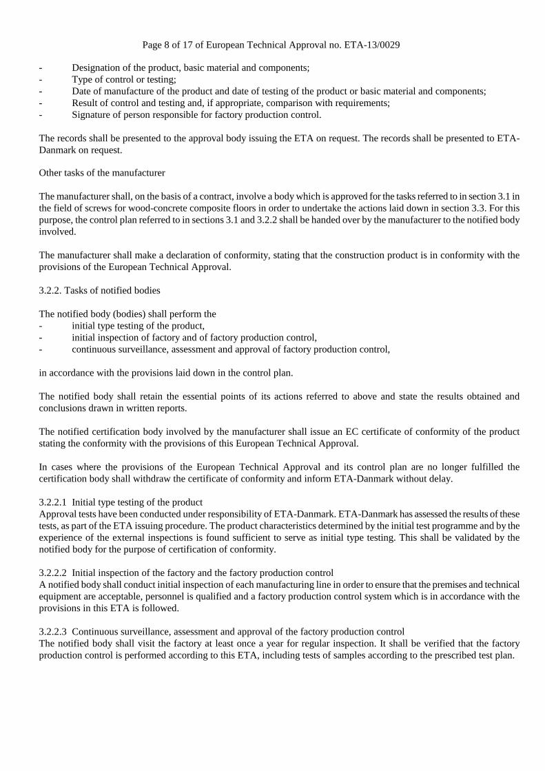
Figure 1.1b Top (left) and side (right) view of a FT-connector
Figure 1.1c Arrangement of ASSY plus VG screws and FT-connectors
Page 12 of 17 of European Technical Approval no. ETA-13/0029
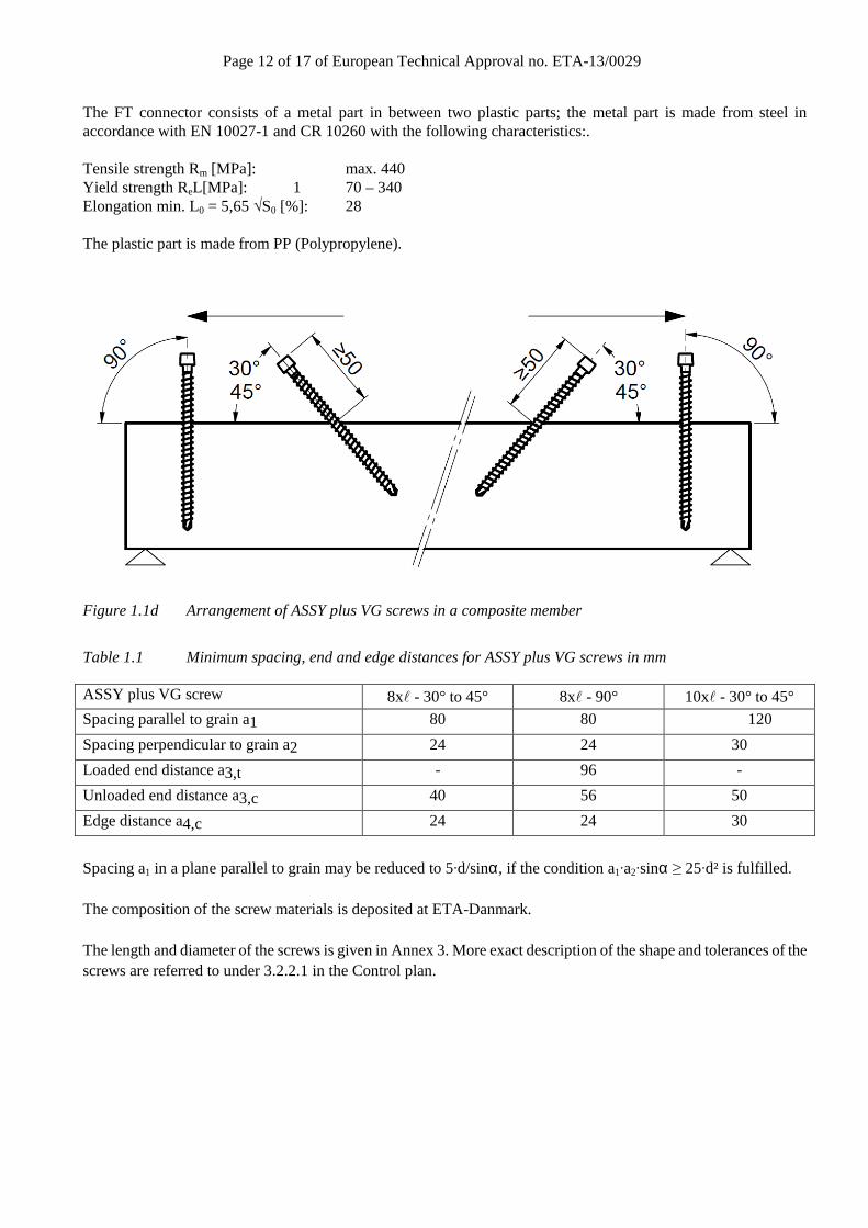
The FT connector consists of a metal part in between two plastic parts; the metal part is made from steel in accordance with EN 10027-1 and CR 10260 with the following characteristics:. Tensile strength Rm [MPa]: max. 440 Yield strength ReL[MPa]: 1 70 – 340 Elongation min. L0 = 5,65 √S0 [%]: 28 The plastic part is made from PP (Polypropylene).
Figure 1.1d Arrangement of ASSY plus VG screws in a composite member
Table 1.1 Minimum spacing, end and edge distances for ASSY plus VG screws in mm
ASSY plus VG screw 8xl - 30° to 45° 8xl - 90° 10xl - 30° to 45°
Spacing parallel to grain a1 80 80 120
Spacing perpendicular to grain a2 24 24 30
Loaded end distance a3,t - 96 -
Unloaded end distance a3,c 40 56 50
Edge distance a4,c 24 24 30
Spacing a1 in a plane parallel to grain may be reduced to 5·d/sinα, if the condition a1·a2·sinα ≥ 25·d² is fulfilled. The composition of the screw materials is deposited at ETA-Danmark. The length and diameter of the screws is given in Annex 3. More exact description of the shape and tolerances of the screws are referred to under 3.2.2.1 in the Control plan.
Page 13 of 17 of European Technical Approval no. ETA-13/0029
ANNEX 2 MECHANICAL PROPERTIES
Resistance and stiffness Structural model Composite members with ASSY plus VG screws are to be designed taking into account the influence of the slip occurring in the joints. A method for the calculation of the load bearing capacity and the deformation of mechanically jointed beams or columns is given in Annexes B and C of Eurocode 5 Part 1-1: General – Common rules and rules for buildings. Calculations should be carried out assuming a linear relationship between force and slip. Alternative methods for the calculation based on numerical models are also applicable. For the determination of the internal forces and moments an elastic behaviour of the concrete may be assumed if the tensile stress in the concrete does not exceed twice the concrete tensile strength. Friction between timber and concrete may only be taken into account, if no interlayer between timber member and concrete is present. In this case, the friction coefficient may be assumed as µ = 0,25. In order to apply the friction between the concrete slab and the timber beam for the calculation of the system, the following conditions shall be fulfilled:
- Static system as single span girder - Predominantly static load - Screws arranged unidirectional with systematically existing compression force between wood and concrete
for reasons of equilibrium - No interlayer
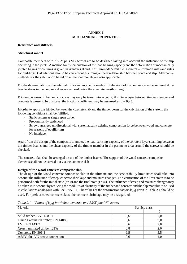
Apart from the design of the composite member, the load-carrying-capacity of the concrete layer spanning between the timber beams and the shear capacity of the timber member in the perimeter area around the screws should be checked. The concrete slab shall be arranged on top of the timber beams. The support of the wood concrete composite elements shall not be carried out via the concrete slab Design of the wood-concrete composite slab The design of the wood-concrete composite slab in the ultimate and the serviceability limit states shall take into account the influence of creep, concrete shrinkage and moisture changes. The verification of the limit states is to be performed both for the initial state (t = 0) and the final state (t = ∞). The influence of creep and moisture changes may be taken into account by reducing the modulus of elasticity of the timber and concrete and the slip modulus to be used in calculations analogous with EN 1995-1-1. The values of the deformation factors kdef given in Table 2.1 should be used. For prefabricated concrete slabs, the concrete shrinkage may be disregarded. Table 2.1 – Values of kdef for timber, concrete and ASSY plus VG screws
Material Service class 1 2
Solid timber, EN 14081-1 0,6 2,0 Glued Laminated timber, EN 14080 0,6 2,0 LVL, EN 14374 0,6 2,0 Cross laminated timber, ETA 0,8 2,0 Concrete, EN 206-1 2,5 2,5 ASSY plus VG screw connection 0,6 4,0
Page 14 of 17 of European Technical Approval no. ETA-13/0029
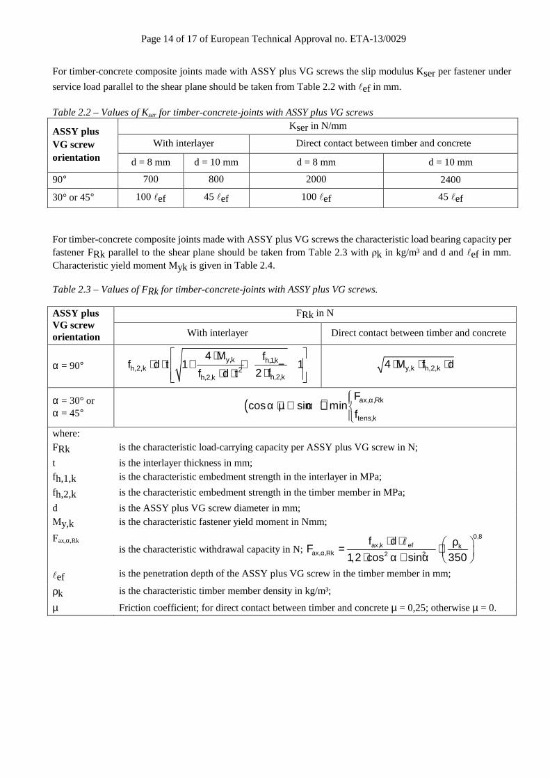
For timber-concrete composite joints made with ASSY plus VG screws the slip modulus Kser per fastener under
service load parallel to the shear plane should be taken from Table 2.2 with lef in mm. Table 2.2 – Values of Kser for timber-concrete-joints with ASSY plus VG screws
ASSY plus VG screw orientation
Kser in N/mm
With interlayer Direct contact between timber and concrete
d = 8 mm d = 10 mm d = 8 mm d = 10 mm
90° 700 800 2000 2400
30° or 45° 100 lef 45 lef 100 lef 45 lef
For timber-concrete composite joints made with ASSY plus VG screws the characteristic load bearing capacity per fastener FRk parallel to the shear plane should be taken from Table 2.3 with ρk in kg/m³ and d and lef in mm. Characteristic yield moment Myk is given in Table 2.4.
Table 2.3 – Values of FRk for timber-concrete-joints with ASSY plus VG screws.
ASSY plus VG screw orientation
FRk in N
With interlayer Direct contact between timber and concrete
α = 90° y,k h,1,k
h,2,k 2h,2,kh,2,k
4 M ff d t 1 1
2 ff d t
⋅⋅ ⋅ + + −
⋅⋅ ⋅
y,k h,2,k4 M f d⋅ ⋅ ⋅
α = 30° or α = 45° ( ) ax, ,Rk
tens,k
Fcos sin min
fαα + µ ⋅ α ⋅
where: FRk is the characteristic load-carrying capacity per ASSY plus VG screw in N;
t is the interlayer thickness in mm; fh,1,k is the characteristic embedment strength in the interlayer in MPa;
fh,2,k is the characteristic embedment strength in the timber member in MPa;
d is the ASSY plus VG screw diameter in mm; My,k is the characteristic fastener yield moment in Nmm;
Fax,α,Rk is the characteristic withdrawal capacity in N;
0,8ax,k ef k
ax, ,Rk 2 2
f dF
1,2 cos sin 350α
⋅ ⋅ ρ = ⋅ ⋅ α + α
l
lef is the penetration depth of the ASSY plus VG screw in the timber member in mm;
ρk is the characteristic timber member density in kg/m³;
µ Friction coefficient; for direct contact between timber and concrete µ = 0,25; otherwise µ = 0.
Page 15 of 17 of European Technical Approval no. ETA-13/0029
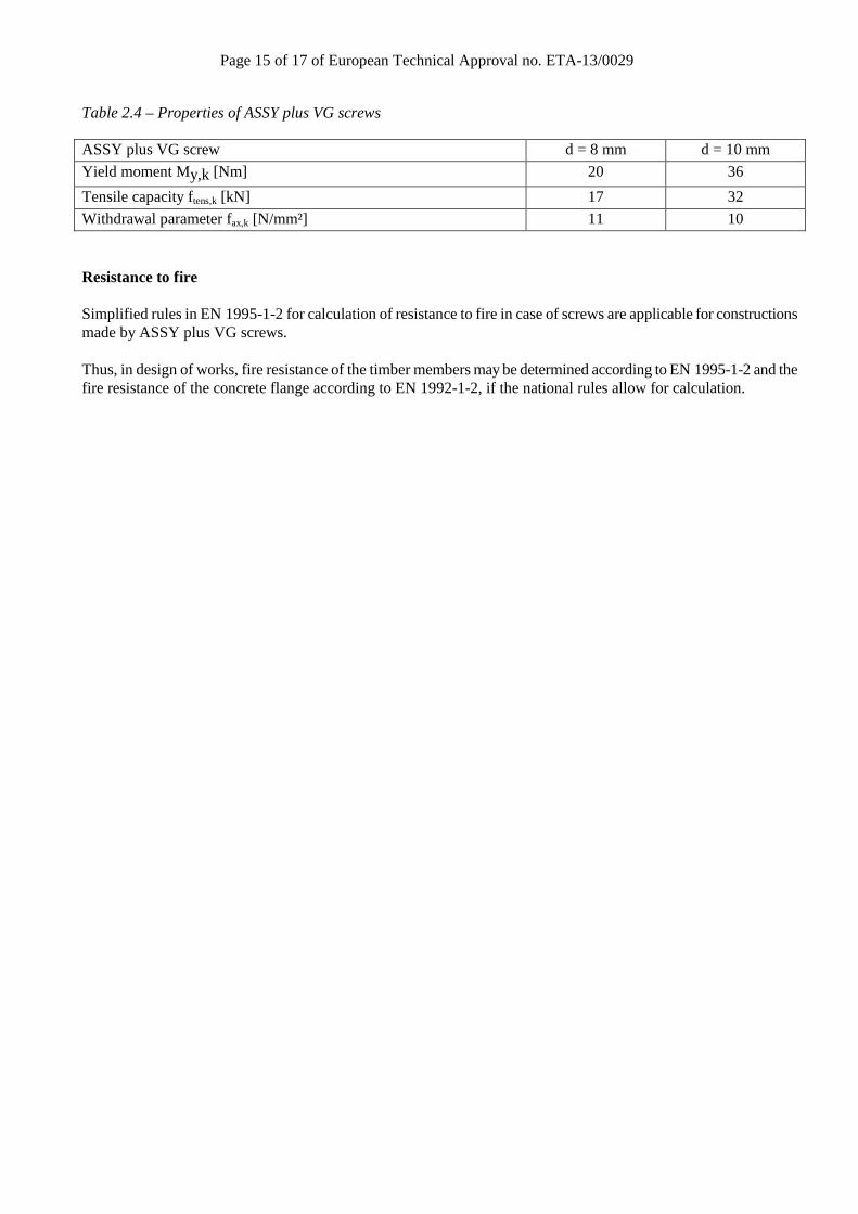
Table 2.4 – Properties of ASSY plus VG screws
ASSY plus VG screw d = 8 mm d = 10 mm
Yield moment My,k [Nm] 20 36
Tensile capacity ftens,k [kN] 17 32
Withdrawal parameter fax,k [N/mm²] 11 10
Resistance to fire Simplified rules in EN 1995-1-2 for calculation of resistance to fire in case of screws are applicable for constructions made by ASSY plus VG screws. Thus, in design of works, fire resistance of the timber members may be determined according to EN 1995-1-2 and the fire resistance of the concrete flange according to EN 1992-1-2, if the national rules allow for calculation.
Page 16 of 17 of European Technical Approval no. ETA-13/0029
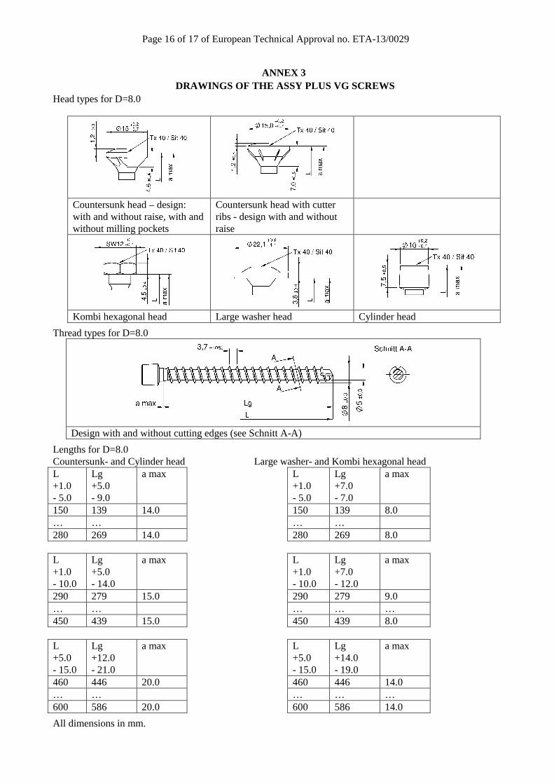
ANNEX 3 DRAWINGS OF THE ASSY PLUS VG SCREWS
Head types for D=8.0
Countersunk head – design: with and without raise, with and without milling pockets
Countersunk head with cutter ribs - design with and without raise
Kombi hexagonal head Large washer head Cylinder head
Thread types for D=8.0
Design with and without cutting edges (see Schnitt A-A)
Lengths for D=8.0 Countersunk- and Cylinder head Large washer- and Kombi hexagonal head L +1.0 - 5.0
Lg +5.0 - 9.0
a max L +1.0 - 5.0
Lg +7.0 - 7.0
a max
150 139 14.0 150 139 8.0 … … … … 280 269 14.0 280 269 8.0 L +1.0 - 10.0
Lg +5.0 - 14.0
a max L +1.0 - 10.0
Lg +7.0 - 12.0
a max
290 279 15.0 290 279 9.0 … … … … … 450 439 15.0 450 439 8.0 L +5.0 - 15.0
Lg +12.0 - 21.0
a max L +5.0 - 15.0
Lg +14.0 - 19.0
a max
460 446 20.0 460 446 14.0 … … … … … 600 586 20.0 600 586 14.0
All dimensions in mm.
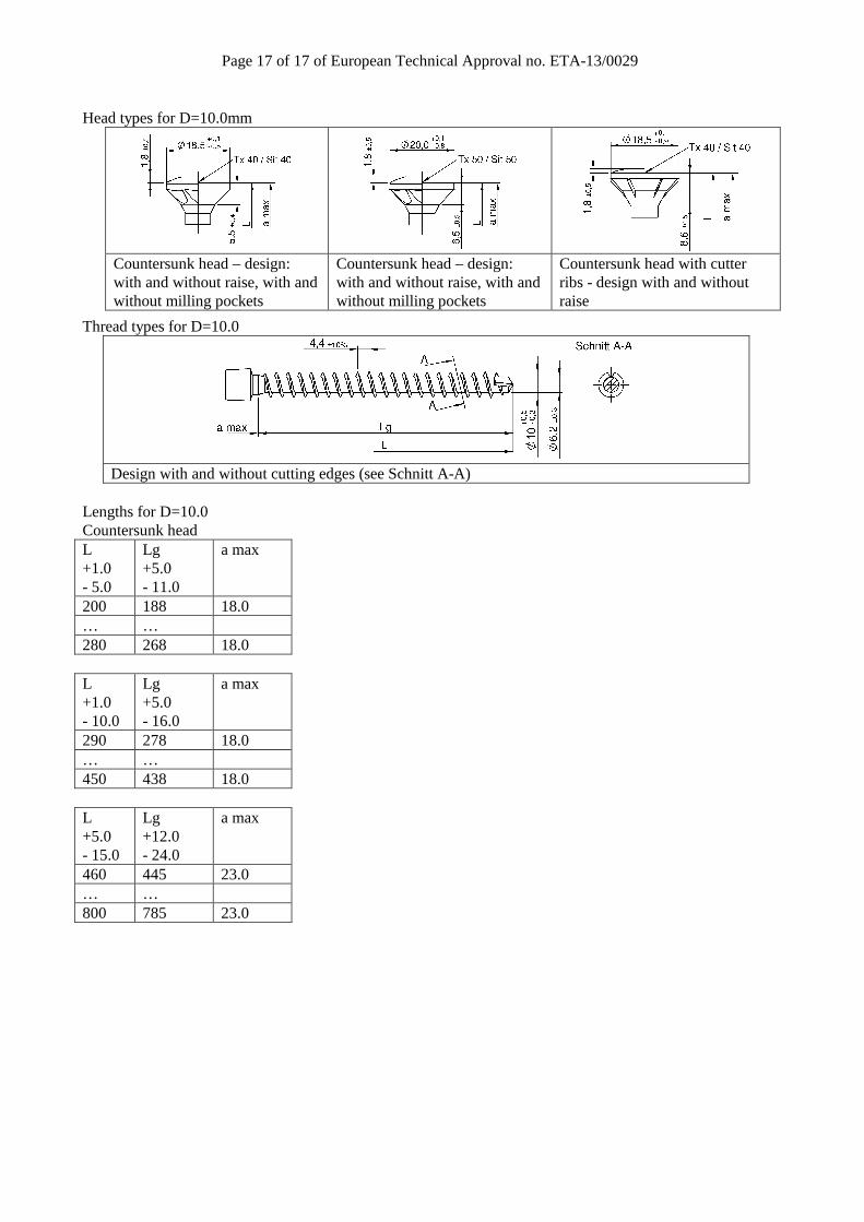
Page 17 of 17 of European Technical Approval no. ETA-13/0029
Head types for D=10.0mm
Countersunk head – design: with and without raise, with and without milling pockets
Countersunk head – design: with and without raise, with and without milling pockets
Countersunk head with cutter ribs - design with and without raise
Thread types for D=10.0
Design with and without cutting edges (see Schnitt A-A)
Lengths for D=10.0 Countersunk head L +1.0 - 5.0
Lg +5.0 - 11.0
a max
200 188 18.0 … … 280 268 18.0 L +1.0 - 10.0
Lg +5.0 - 16.0
a max
290 278 18.0 … … 450 438 18.0 L +5.0 - 15.0
Lg +12.0 - 24.0
a max
460 445 23.0 … … 800 785 23.0