european technical approval eta 10/0414 - eurobungalow
TRANSCRIPT
Organización Europea para la Idoneidad Técnica European Organisation for Technical Approvals
The Catalonia Institute of Construction Technology Wellington, 19 E-08018, Barcelona Tel.: (+34) 93 309 34 04 Fax: (+34) 93 300 48 52 [email protected] www.itec.cat
Member of EOTA
European Technical Approval ETA 10/0414
Nombre comercial Trade name
EURODOM EURODOM
Titular del DITE Holder of approval
Euro Bungalow SL Navas de Tolosa 260-262 E-08027 Barcelona, Spain Tel. +34 935 349 222 Fax +34 935 349 435
Tipo genérico y uso del producto de construcción
Kit de construcción de edificios de estructura de madera para viviendas unifamiliares aisladas con una altura máxima de dos plantas (planta baja + 1)
Generic type and use of construction product
Timber frame building kit for construction of detached single-family two storey houses maximum ground + top floor
Validez: Validity:
de from
03.12.2010
hasta to
02.12.2015
Planta de fabricación Manufacturing plant
Eurodom Sp. z.o.o. Tarnawatka Tartak ul. Tomaszowska 1922-604 Tarnawatka, Poland
El presente Documento de Idoneidad Técnica Europeo contiene
62 páginas, incluyendo anexos 1, 2 y 3 que forman parte del documento
This European Technical Approval contains
62 pages, including annexes 1, 2 and 3 which form an integral part of the document
Autorizado y notificado con arreglo
al artículo 10 de la Directiva 89/106/CEE del Consejo, de 21 de diciembre de 1988, relativa a la aproximación de las disposiciones l e ga le s , r eg l a me n ta r i as y administrativas de los Estados miembros sobre los productos de construcción
Page 2 of 62 ETA-10/0414, issued on 03.12.2010
TABLE OF CONTENTS
I LEGAL BASES AND GENERAL CONDITIONS ................ ......................................................... 3
II SPECIFIC CONDITIONS OF THE EUROPEAN TECHNICAL APPRO VAL ............................... 4
1 Definition of products and intended use ........... ....................................................................... 4
1.1 Definition of the construction product (kit) .................................................................................... 4 1.2 Intended use ................................................................................................................................. 5
2 Characteristics of products and methods of verifica tion .............................................. ......... 6
2.1 Mechanical resistance and stability (ER 1) ................................................................................... 6 2.2 Safety in case of fire (ER 2) .......................................................................................................... 7 2.3 Hygiene, health and environment (ER 3) ...................................................................................... 7 2.4 Safety in use (ER 4) ...................................................................................................................... 9 2.5 Protection against noise (ER 5) .................................................................................................... 9 2.6 Energy economy and heat retention (ER 6) ............................................................................... 11 2.7 Aspects of durability, serviceability and identification ................................................................. 13
3 Evaluation and attestation of conformity and CE mar king .............................................. .... 15
3.1 System of attestation of conformity ............................................................................................. 15 3.2 Responsibilities ........................................................................................................................... 15 3.3 CE marking ................................................................................................................................. 16
4 Assumptions under which the fitness of the product for the intended use is favourably assessed ............................... .................................................................................. 17
4.1 Local building regulations ........................................................................................................... 17 4.2 Structural design ......................................................................................................................... 17 4.3 Manufacturing ............................................................................................................................. 17 4.4 Substructure ................................................................................................................................ 17 4.5 Installation ................................................................................................................................... 17
5 Recommendations ................................... ................................................................................. 18
5.1 Packaging, transport and storage ............................................................................................... 18 5.2 Use, maintenance, repair ............................................................................................................ 18
Annex 1 – Configuration of main assembled component s ...................................................................... 19
Annex 2 – Material and component specifications ... ................................................................................ 28
Annex 3 – Essential construction details .......... ........................................................................................ 32
Page 3 of 62 ETA-10/0414, issued on 03.12.2010
I LEGAL BASES AND GENERAL CONDITIONS
1 This European Technical Approval is issued by the Catalonia Institute of Construction Technology (ITeC) in accordance with:
− Council Directive 89/106/EEC of 21 December 1988 on the approximation of laws, regulations and administrative provisions of Member States relating to construction products1, modified by Council Directive 93/68/EEC2 and Regulation (EC) N°1882/2003 of the European Par liament and of the Council3;
− Real Decreto 1630/1992, de 29 de diciembre, por el que se dictan disposiciones para la libre circulación de productos de construcción en aplicación de la Directiva 89/106/CEE4;
Real Decreto 1328/1995, de 28 de julio, por el que se modifican, en aplicación de la Directiva 93/68/CEE, las disposiciones para la libre circulación aprobadas por el Real Decreto 1630/1992, de 29 de diciembre. (BOE 19-8-95) y la Orden CTE/2276/2002 de 4 de septiembre;
− Common Procedural Rules for Requesting, Preparing and the Granting of European Technical Approvals set out in the Annex to Commission Decision 94/23/EC5;
− Guideline for European Technical Approval No. 007 Timber Frame Building Kits, edition April 2001. 2 The Catalonia Institute of Construction Technology (ITeC) is authorized to check whether the provisions
of this European Technical Approval are met. Checking may take place in the manufacturing plant. Nevertheless, the responsibility for the conformity of the products to the European Technical Approval and for their fitness for the intended use remains with the holder of the European Technical Approval.
3 This European Technical Approval is not to be transferred to manufacturers or agents of manufacturers
other than those indicated on page 1, or manufacturing plants other than those indicated on page 1 laid down in the context of this European Technical Approval.
4 This European Technical Approval may be withdrawn by the Catalonia Institute of Construction
Technology (ITeC), in particular pursuant to information by the Commission according to Article 5(1) of Council Directive 89/106/EEC.
5 Reproduction of this European Technical Approval including transmission by electronic means shall be
in full. However, partial reproduction can be made with the written consent of the Catalonia Institute of Construction Technology (ITeC). In this case partial reproduction has to be designated as such. Texts and drawings of advertising brochures shall not contradict or misuse the European Technical Approval.
6 The European Technical Approval is issued in Spanish by the Catalonia Institute of Construction
Technology (ITeC). This version corresponds fully to the version circulated in EOTA. Translations into other languages have to be designated as such.
1 Official Journal of the European Communities N° L 40 , 11.2.1989, p. 12 2 Official Journal of the European Communities N° L 220, 30.8.1993, p. 1 3 Official Journal of the European Union N° L 284, 3 1.10.2003, p. 25 4 Boletín Oficial del Estado nº 34 de 9 de febrero de 1993 5 Official Journal of the European Communities N° L 17, 20.1.1994, p. 34
Page 4 of 62 ETA-10/0414, issued on 03.12.2010
II SPECIFIC CONDITIONS OF THE EUROPEAN TECHNICAL AP PROVAL
1 Definition of products and intended use
1.1 Definition of the construction product (kit) EURODOM is an industrially prepared timber frame building kit that is made of pre-designed and prefabricated components.
Walls are manufactured as prefabricated structural frames based on pre-cut timber members supplemented with additional materials on site. Roofs and floors are assembled from glued laminated timber joists bought in the open market. Glued laminated timber members used in columns are also bought in the open market.
The kits are prepared in the factory for every individual house, delivered as a package, and assembled on site.
Spacing between pre-cut solid wood members, height and width of prefabricated structural frames of walls, as well as the dimensions of glued laminated timber joists and columns vary according to the design process for every particular application. The variations are within a range. The configuration of the main assembled components is shown in annex 1. Material and component specifications are shown in annex 2. The essential construction details including their joints are described in annex 3.
The content of the kit includes the loadbearing structures and their connections, the connections to the substructure, thermal insulation, internal linings, vapour control layers, treated bottom plates, claddings, sheathings, roof coverings and windows.
The inner surface coverings (paints or varnishes) are not included in the kit.
Doors, stairs, balconies, internal fittings, technical installations for water, heating, cooling, ventilation, foundations and other components which are necessary to form a complete house are not part of the kit. They should meet their respective regulations.
Page 5 of 62 ETA-10/0414, issued on 03.12.2010
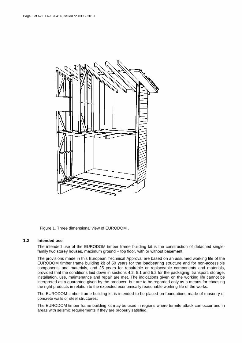
Figure 1. Three dimensional view of EURODOM .
1.2 Intended use The intended use of the EURODOM timber frame building kit is the construction of detached single-family two storey houses, maximum ground + top floor, with or without basement.
The provisions made in this European Technical Approval are based on an assumed working life of the EURODOM timber frame building kit of 50 years for the loadbearing structure and for non-accessible components and materials, and 25 years for repairable or replaceable components and materials, provided that the conditions laid down in sections 4.2, 5.1 and 5.2 for the packaging, transport, storage, installation, use, maintenance and repair are met. The indications given on the working life cannot be interpreted as a guarantee given by the producer, but are to be regarded only as a means for choosing the right products in relation to the expected economically reasonable working life of the works.
The EURODOM timber frame building kit is intended to be placed on foundations made of masonry or concrete walls or steel structures.
The EURODOM timber frame building kit may be used in regions where termite attack can occur and in areas with seismic requirements if they are properly satisfied.
Page 6 of 62 ETA-10/0414, issued on 03.12.2010
2 Characteristics of products and methods of verifi cation
2.1 Mechanical resistance and stability (ER 1) The properties of structural materials and components related to mechanical resistance and stability are expressed in terms of indication of geometrical data and properties of the materials and constituent products used6, which includes:
- the geometrical data (dimensions and cross sections, including tolerances) of the installed system and the components of the kit, and
- the properties of the materials and constituent products used that are needed to determine, according to the National Provisions, valid in the place of use, or possible use, loadbearing capacities and other properties, including aspects of durability and serviceability, of the assembled system installed in the works.
The necessary information for the mechanical resistance and stability for each loadbearing building component, as well as the joints between components, is listed in annex 1 and 2. The main assembled components configurations are listed in annex 1. The properties of structural materials and components are listed in annex 2.
The mechanical resistance and stability of each loadbearing building component as well as the joints between components are to be determined on the basis of this exact description. During the calculation the respective requirements of each member states shall be taken into account.
Basic calculations are done according to EN 1995-1-17, and are adapted according to the requirements of national construction regulations.
All structural timber elements are classified in service class 1 except suspended ground floor which is classified in service class 2. Values of kmod (modification factor for duration of load and moisture content) and kdef (deformation factor) are chosen following the recommendations in EN 1995-1-1. kmod is chosen according to the corresponding service class and the load-duration class, and kdef is chosen according to the corresponding service class.
System strength factor (ksys) is considered 1,10 in structural walls, floor and roof frames based on the capability of the load-distribution system of transferring the loads from one member to the neighbouring members.
Partial factor value for material properties and resistances at ultimate limit state are as follows:
- γM = 1,30 for solid timber; - γM = 1,25 for glued laminated timber; - γM = 1,20 for OSB; - γM = 1,30 for connections;
and is 1,00 for serviceability limit state.
The deformation criteria for floors and roofs satisfy the national determined parameters.
OSB/3 panels fixed on external, and if necessary internal walls, contribute to the racking resistance.
Partial safety factors:
- γG = 1,35 for permanent actions; - γG = 1,50 for variable actions;
The resistance against seismic actions may be calculated in the building project of each individual work for the specific structural design, on the basis of the racking resistance and the anchorage capacities given below, and the densities and total mass taken from annex 1 and annex 2.
Racking resistance is obtained according to method A in EN 1995-1-1.
6 It corresponds with the method 1 in Guidance Paper L “Application and use of Eurocodes” (version 27 November
2003). 7 The reference to EN 1995-1-1 in this document means reference to EN 1995-1-1: 2006.
Page 7 of 62 ETA-10/0414, issued on 03.12.2010
Racking resistance must be obtained for each specific design by means of the lateral design capacity of an individual fastener (Ff,Rd) 3,0 x 40 mm, and using a OSB/3 panel 12 mm thick.
Ff,Rd = 216,93 N;
The value of Fi,v,Rd may be obtained for each panel depending on the wall panel width, the coefficient ci and the fastener spacing.
Fv,Rd may be obtained by means of the following: Fv,Rd = Σ Fi,v,Rd.
Anchorage capacities:
• metal anchors: values shall be obtained from CE marking;
• screws 5,0 x 90 mm used in timber to timber connexions: fax,K = 23,57 N; Fax,90,Rk = nef·4.080,63 N;
2.2 Safety in case of fire (ER 2)
2.2.1 Reaction to fire
Classification in accordance with Euroclasses A1 – F in EN 13501-1 of the components in the assembled kits is shown in annex 2.
2.2.2 Resistance to fire
The properties related to resistance to fire for loadbearing building components are expressed in terms of indication of geometrical data of the component and constituent products used8, due to the variability of configurations of the components. Spacing between pre-cut solid wood members in walls, height and width of prefabricated structural frames, as well as spacing and dimensions of glued laminated timber joists and columns vary according to the specific structural design for every particular application. Resistance to fire must be determined case by case according to each specific structural design.
2.2.3 External fire performance of the roof coverin g
External fire performance of concrete, slate and clay roofing tiles is considered “deemed to satisfy” all the provisions for external fire performance without the need for testing on the basis that they are included within the definitions given in EC decision 2000/553/EC and provided that any national provisions on the design and execution of works are fulfilled.
External fire performance of concrete, slate and clay roofing tiles according to EN 13501-5 is given in annex 2.
2.3 Hygiene, health and environment (ER 3)
2.3.1 Vapour permeability and moisture resistance
The assessment with respect to both interstitial and internal surface condensation shows that the kit provides adequate moisture control for the intended use, taking into account the geographical restrictions specified in cl. 1.2.
Where the climate so requires, the risk of moisture condensation has to be assessed for each individual work. A vapour control layer in the warm side of the thermal insulation of the roof could be necessary.
2.3.2 Watertightness
The kit has been favourably assessed primarily on the basis of the construction details and later by carrying out laboratory tests of the external envelopes of façades, for the specified areas of intended use.
8 It corresponds with the method 1 in Guidance Paper L Application and use of Eurocodes (version 27 November
2003).
Page 8 of 62 ETA-10/0414, issued on 03.12.2010
The ventilated air space 35 mm thick behind the external envelope of façades together with the waterproofing membrane attached to the timber frame, provide watertightness properties, so water leakage does not occur through the timber frame nor through the thermal insulation.
Watertight internal surfaces are not a part of the kit.
2.3.3 Release of dangerous substances
The manufacturer has submitted a written declaration stating the dangerous substances in the kit.
- Biocides:
As long as the annexes of the Commission Directive 98/8/CE of the European Parliament and of the Council are not implemented, the biocides used in the coating system applied over the external timber cladding and in the treated bottom plates are registered in the Registro de plaguicidas no agrícolas o biocidas which maintains the Spanish authorities -Ministerio de Sanidad y Consumo- following the measures of implementation of the Commission Directive 98/8/CE.
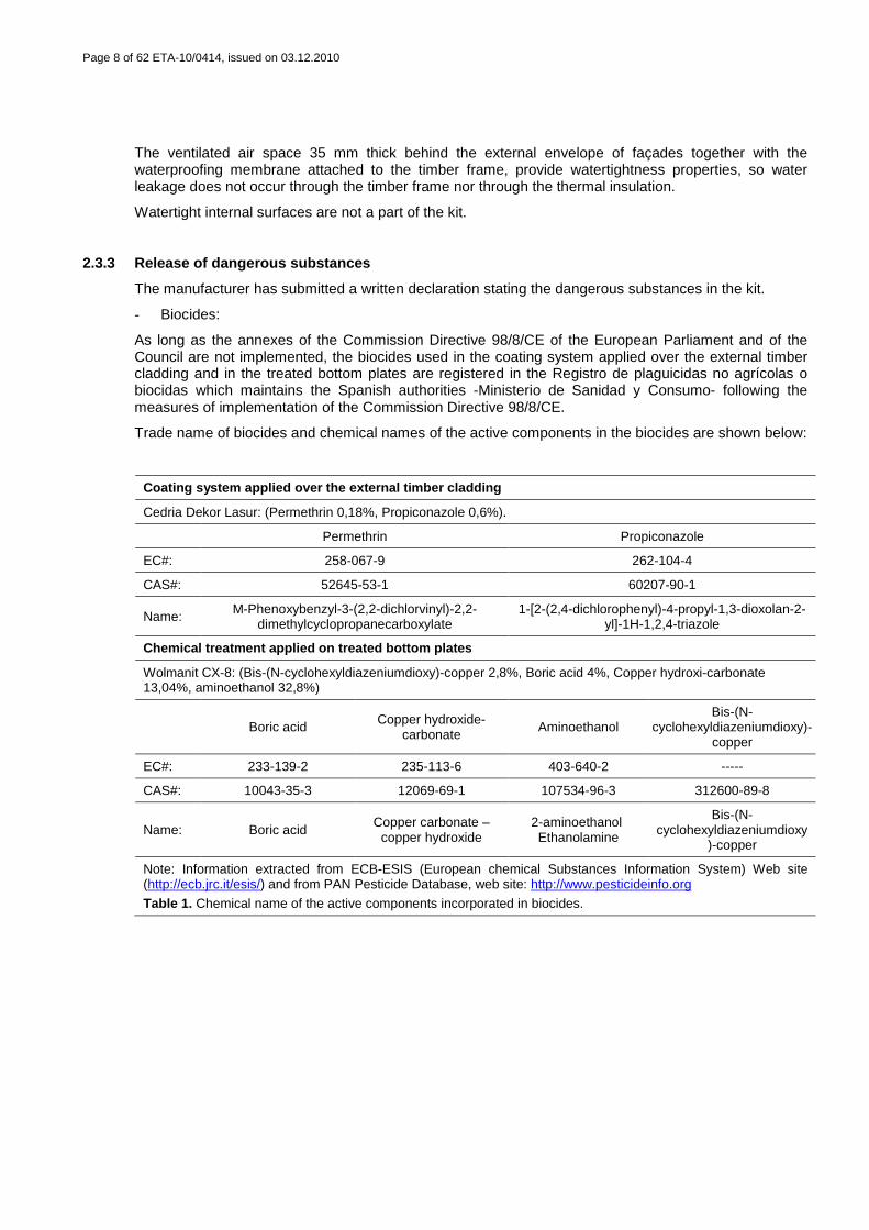
Trade name of biocides and chemical names of the active components in the biocides are shown below:
Coating system applied over the external timber cla dding
Cedria Dekor Lasur: (Permethrin 0,18%, Propiconazole 0,6%).
Permethrin Propiconazole
EC#: 258-067-9 262-104-4
CAS#: 52645-53-1 60207-90-1
Name: M-Phenoxybenzyl-3-(2,2-dichlorvinyl)-2,2-dimethylcyclopropanecarboxylate
1-[2-(2,4-dichlorophenyl)-4-propyl-1,3-dioxolan-2-yl]-1H-1,2,4-triazole
Chemical treatment applied on t reated bottom plates
Wolmanit CX-8: (Bis-(N-cyclohexyldiazeniumdioxy)-copper 2,8%, Boric acid 4%, Copper hydroxi-carbonate 13,04%, aminoethanol 32,8%)
Boric acid Copper hydroxide-carbonate
Aminoethanol Bis-(N-
cyclohexyldiazeniumdioxy)-copper
EC#: 233-139-2 235-113-6 403-640-2 -----
CAS#: 10043-35-3 12069-69-1 107534-96-3 312600-89-8
Name: Boric acid Copper carbonate –
copper hydroxide 2-aminoethanol Ethanolamine
Bis-(N-cyclohexyldiazeniumdioxy
)-copper
Note: Information extracted from ECB-ESIS (European chemical Substances Information System) Web site (http://ecb.jrc.it/esis/) and from PAN Pesticide Database, web site: http://www.pesticideinfo.org
Table 1. Chemical name of the active components incorporated in biocides.
Page 9 of 62 ETA-10/0414, issued on 03.12.2010
- Formaldehyde:
The formaldehyde content of OSB/3 panels is class E1 in accordance with annex B of EN 13986.
The formaldehyde content in glued laminated timber is E1 in accordance with annex B of EN 14080.
Note: In addition to the specific clauses relating to dangerous substances contained in this European Technical Approval, there may be other requirements applicable to the products falling within its scope (e.g. transposed European legislation and national laws, regulations and administrative provisions). In order to meet the provisions of the Construction Products Directive, these requirements need also to be complied with, when and where they apply.
2.4 Safety in use (ER 4)
2.4.1 Slipperiness of floor finishes
No performance determined for slipperiness of floor finishes.
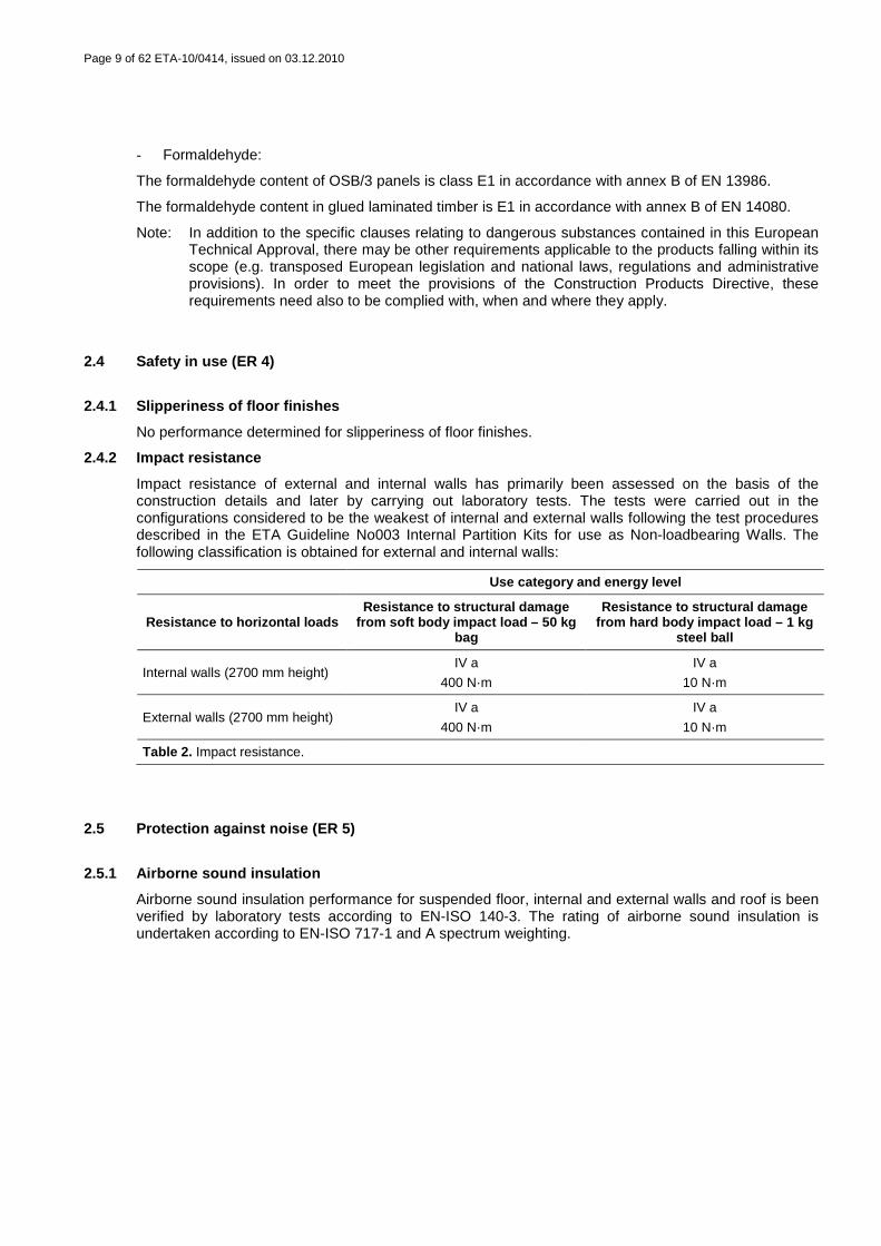
2.4.2 Impact resistance
Impact resistance of external and internal walls has primarily been assessed on the basis of the construction details and later by carrying out laboratory tests. The tests were carried out in the configurations considered to be the weakest of internal and external walls following the test procedures described in the ETA Guideline No003 Internal Partition Kits for use as Non-loadbearing Walls. The following classification is obtained for external and internal walls:
Use category and energy level
Resistance to horizontal loads Resistance to structural damage
from soft body impact load – 50 kg bag
Resistance to structural damage from hard body impact load – 1 kg
steel ball
Internal walls (2700 mm height) IV a
400 N·m
IV a
10 N·m
External walls (2700 mm height) IV a
400 N·m
IV a
10 N·m
Table 2. Impact resistance.
2.5 Protection against noise (ER 5)
2.5.1 Airborne sound insulation
Airborne sound insulation performance for suspended floor, internal and external walls and roof is been verified by laboratory tests according to EN-ISO 140-3. The rating of airborne sound insulation is undertaken according to EN-ISO 717-1 and A spectrum weighting.
Page 10 of 62 ETA-10/0414, issued on 03.12.2010
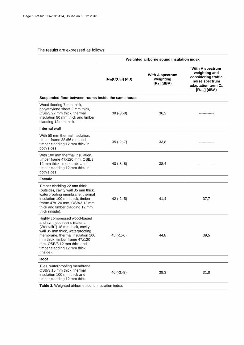
The results are expressed as follows:
Weighted airborne sound insulation index
[RW(C;Ctr)] (dB) With A spectrum
weighting [RA] (dBA)
With A spectrum weighting and
considering traffic noise spectrum
adaptation term C tr [RA,tr] (dBA)
Suspended floor between rooms inside the same house
Wood flooring 7 mm thick, polyethylene sheet 2 mm thick, OSB/3 22 mm thick, thermal insulation 50 mm thick and timber cladding 12 mm thick.
38 (-3;-8) 36,2 ------------
Internal wall
With 50 mm thermal insulation, timber frame 38x56 mm and timber cladding 12 mm thick in both sides
35 (-2;-7) 33,8 ------------
With 100 mm thermal insulation, timber frame 47x120 mm, OSB/3 12 mm thick in one side and timber cladding 12 mm thick in both sides.
40 (-3;-8) 38,4 ------------
Façade
Timber cladding 22 mm thick (outside), cavity wall 35 mm thick, waterproofing membrane, thermal insulation 100 mm thick, timber frame 47x120 mm, OSB/3 12 mm thick and timber cladding 12 mm thick (inside).
42 (-2;-5) 41,4 37,7
Highly compressed wood-based and synthetic resins material (Werzalit©) 18 mm thick, cavity wall 35 mm thick, waterproofing membrane, thermal insulation 100 mm thick, timber frame 47x120 mm, OSB/3 12 mm thick and timber cladding 12 mm thick (inside).
45 (-1;-6) 44,8 39,5
Roof
Tiles, waterproofing membrane, OSB/3 15 mm thick, thermal insulation 100 mm thick and timber cladding 12 mm thick.
40 (-3;-8) 38,3 31,8
Table 3. Weighted airborne sound insulation index.
Page 11 of 62 ETA-10/0414, issued on 03.12.2010
2.5.2 Impact sound insulation
No performance determined for impact sound insulation.
2.5.3 Sound absorption
No performance determined for sound absorption.
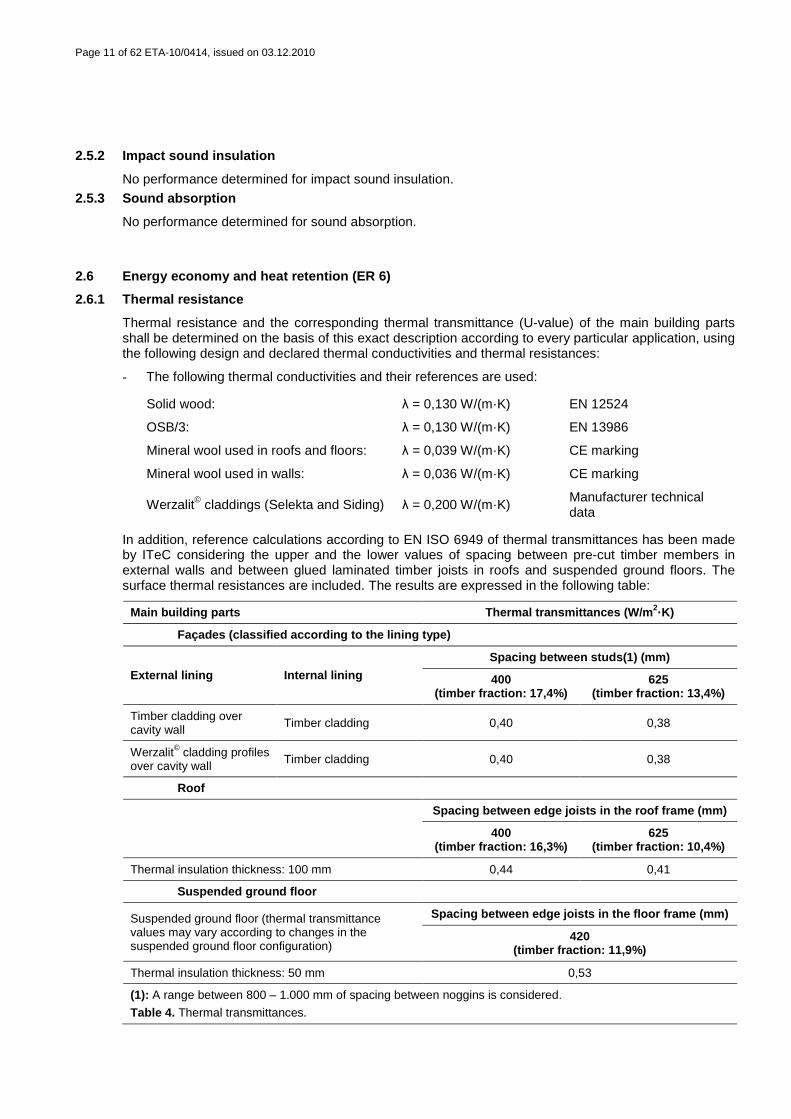
2.6 Energy economy and heat retention (ER 6)
2.6.1 Thermal resistance
Thermal resistance and the corresponding thermal transmittance (U-value) of the main building parts shall be determined on the basis of this exact description according to every particular application, using the following design and declared thermal conductivities and thermal resistances:
- The following thermal conductivities and their references are used:
Solid wood: λ = 0,130 W/(m·K) EN 12524
OSB/3: λ = 0,130 W/(m·K) EN 13986
Mineral wool used in roofs and floors: λ = 0,039 W/(m·K) CE marking
Mineral wool used in walls: λ = 0,036 W/(m·K) CE marking
Werzalit© claddings (Selekta and Siding) λ = 0,200 W/(m·K) Manufacturer technical data
In addition, reference calculations according to EN ISO 6949 of thermal transmittances has been made by ITeC considering the upper and the lower values of spacing between pre-cut timber members in external walls and between glued laminated timber joists in roofs and suspended ground floors. The surface thermal resistances are included. The results are expressed in the following table:
Main building parts Thermal transmittances (W/m 2·K)
Façades (classified according to the lining type)
External lining Internal lining
Spacing between studs(1) (mm)
400 (timber fraction: 17,4%)
625 (timber fraction: 13,4%)
Timber cladding over cavity wall Timber cladding 0,40 0,38
Werzalit© cladding profiles over cavity wall Timber cladding 0,40 0,38
Roof
Spacing between edge joists in the roof frame (mm)
400 (timber fraction: 16,3%)
625 (timber fraction: 10,4%)
Thermal insulation thickness: 100 mm 0,44 0,41
Suspended ground floor
Suspended ground floor (thermal transmittance values may vary according to changes in the suspended ground floor configuration)
Spacing between edge joists in the floor frame (mm)
420 (timber fraction: 11,9%)
Thermal insulation thickness: 50 mm 0,53
(1): A range between 800 – 1.000 mm of spacing between noggins is considered.
Table 4. Thermal transmittances.

Page 12 of 62 ETA-10/0414, issued on 03.12.2010
No performance determined for thermal resistance of windows. Windows are included in the kit but not considered in thermal calculations because of their dependence on the particular features of each project. Doors are not included in the kit.
2.6.2 Air permeability
Air permeability has been assessed by carrying out a laboratory test of the window according to EN 1026:2000.
Air permeability (m 3/hm 2) (100 Pa)
Positive pressure Negative pressure Pressures average
According to the total area 5,72 5,89 5,80
According to the opening joint length 1,33 1,37 1,35
Table 5. Air permeability.
Air permeability classification of the window according to EN 12207:2000:
Window Classification
Double hinged wood window A3 class
Table 6. Air permeability classification.
No performance determined for air permeability of opaque areas.
2.6.3 Thermal inertia
No performance determined for thermal inertia.
Page 13 of 62 ETA-10/0414, issued on 03.12.2010
2.7 Aspects of durability, serviceability and ident ification
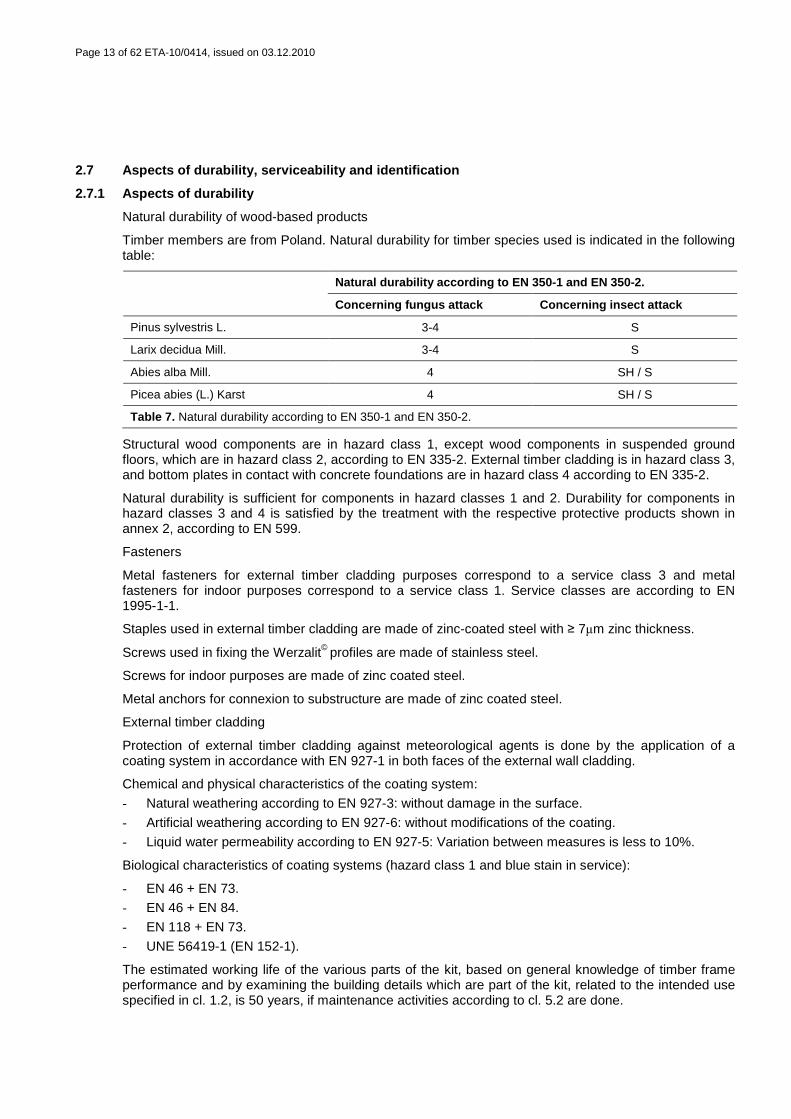
2.7.1 Aspects of durability
Natural durability of wood-based products
Timber members are from Poland. Natural durability for timber species used is indicated in the following table:
Natural durability according to EN 350-1 and EN 350-2 .
Concerning fungus attack Concerning insect attack
Pinus sylvestris L. 3-4 S
Larix decidua Mill. 3-4 S
Abies alba Mill. 4 SH / S
Picea abies (L.) Karst 4 SH / S
Table 7. Natural durability according to EN 350-1 and EN 350-2.
Structural wood components are in hazard class 1, except wood components in suspended ground floors, which are in hazard class 2, according to EN 335-2. External timber cladding is in hazard class 3, and bottom plates in contact with concrete foundations are in hazard class 4 according to EN 335-2.
Natural durability is sufficient for components in hazard classes 1 and 2. Durability for components in hazard classes 3 and 4 is satisfied by the treatment with the respective protective products shown in annex 2, according to EN 599.
Fasteners
Metal fasteners for external timber cladding purposes correspond to a service class 3 and metal fasteners for indoor purposes correspond to a service class 1. Service classes are according to EN 1995-1-1.
Staples used in external timber cladding are made of zinc-coated steel with ≥ 7µm zinc thickness.
Screws used in fixing the Werzalit© profiles are made of stainless steel.
Screws for indoor purposes are made of zinc coated steel.
Metal anchors for connexion to substructure are made of zinc coated steel.
External timber cladding
Protection of external timber cladding against meteorological agents is done by the application of a coating system in accordance with EN 927-1 in both faces of the external wall cladding.
Chemical and physical characteristics of the coating system:
- Natural weathering according to EN 927-3: without damage in the surface.
- Artificial weathering according to EN 927-6: without modifications of the coating.
- Liquid water permeability according to EN 927-5: Variation between measures is less to 10%.
Biological characteristics of coating systems (hazard class 1 and blue stain in service):
- EN 46 + EN 73.
- EN 46 + EN 84.
- EN 118 + EN 73.
- UNE 56419-1 (EN 152-1).
The estimated working life of the various parts of the kit, based on general knowledge of timber frame performance and by examining the building details which are part of the kit, related to the intended use specified in cl. 1.2, is 50 years, if maintenance activities according to cl. 5.2 are done.
Page 14 of 62 ETA-10/0414, issued on 03.12.2010
2.7.2 Aspects of serviceability
Deflections of floor, roof and glued laminated timber joists are to be determined on the basis of their exact description, and according to each building project.
Values for maximum deflections of floor and roof joists on two supports, and in glued laminated timber joists at serviceability limit states are as follows. Span values are doubled in cantilevered joists.
- 1/300 of the span, produced for permanent actions in its characteristic value and variable actions in characteristic value and in combination values.
- 1/350 of the span, produced for permanent actions in characteristic value and for short-length variable actions in characteristic value and in combination values.
- 1/300 of the span, produced for permanent actions in characteristic value and variable actions in quasi-permanent value (ψ2 · Qk).
Suspended floors will satisfy the criteria for stiffness against vibrations if they satisfy the limiting values for deflections indicated above, according to the Spanish Building Technical Code.
2.7.3 Identification
The Identification parameters for materials and components of the kit are shown in annex 2 of this European Technical Approval. The way in which they are assembled is shown in annex 3.
Page 15 of 62 ETA-10/0414, issued on 03.12.2010
3 Evaluation and attestation of conformity and CE m arking
3.1 System of attestation of conformity
According to the Decision 1999/455/EC of the European Commission9 system 1 of the attestation of conformity applies.
This system of attestation of conformity is defined as follows:
System 1: Certification of the conformity of the product by an approved certification body on the basis of:
(a) Tasks for the manufacturer:
(1) Factory production control; (2) Further testing of samples taken at the factory by the manufacturer in accordance with a
prescribed test plan;
(b) Tasks for the approved body:
(3) Initial type testing of the product; (4) Initial inspection of factory and of factory production control; (5) Continuous surveillance, assessment and approval of factory production control.
Note: Approved bodies are also referred to as "notified bodies".
3.2 Responsibilities
3.2.1 Tasks for the manufacturer
The manufacturer shall, on the basis of a contract, involve a body which is approved for the tasks referred to in section 3.1 in the field of EURODOM timber frame building kit in order to undertake the actions laid down in section 3.3. For this purpose, the "control plan" referred to in sections 3.2.1.1 and 3.2.2 shall be handed over by the manufacturer to the approved body or bodies involved.
3.2.1.1 Factory production control
The manufacturer shall exercise permanent internal control of production. All the elements, requirements and provisions adopted by the manufacturer shall be documented in a systematic manner in the form of written policies and procedures, including records of results performed. This production control system shall insure that the product is in conformity with this European Technical Approval.
The manufacturer may only use incoming materials stated in the technical documentation of this European Technical Approval.
The factory production control shall be in accordance with the "Control plan of 08-07-2010 relating to the European Technical Approval 10/0414 issued on 03.12.2010" which is part of the technical documentation of this European Technical Approval. The "control plan" is laid down in the context of the factory production control system operated by the manufacturer and deposited within the Catalonia Institute of Construction Technology (ITeC).10
The results of factory production control shall be recorded and evaluated in accordance with the provisions of the "control plan".
3.2.1.2 Testing of samples taken at the factory
Testing of samples according to a prescribed test plan is not required. A continuous visual checking and checking of component dimensions is prescribed.
9 Official Journal of the European Communities L 178, 14.07.1999 10 The "control plan" is a confidential part of the European Technical Approval and only handed over to the
approved body or bodies involved in the procedure of attestation of conformity. See section 3.2.2.
Page 16 of 62 ETA-10/0414, issued on 03.12.2010
3.2.1.3 Declaration of Conformity
The manufacturer shall make a declaration of conformity, stating that the construction product is in conformity with the provisions of this European Technical Approval 10/0414 issued on 03.12.2010.
3.2.2 Tasks for the approved bodies
The approved body shall perform the activities referred to above according to the specific conditions, in accordance with the provisions laid down in the “control plan”.
The approved body shall retain the essential points of their actions and state the results obtained and conclusions drawn in a written report.
3.2.2.1 Initial type testing of the product
Initial assessment of the EURODOM timber frame building kit has been carried out by the approval body and provides the basis for the initial product assessment for the notified body.
3.2.2.2 Initial inspection of factory and of factory production control
The notified body shall assess the factory production control system to demonstrate that the factory production control is in conformity with this European Technical Approval and any subsidiary information. The notified body shall ensure that the manufacturer has acceptable premises, technical equipment and competent staff to produce the EURODOM timber frame building kit as described in this European Technical Approval.
3.2.2.3 Continuous surveillance, assessment and approval of factory production control
The notified body shall visit the factory for surveillance inspections twice a year to ensure continuous conformity of the factory production control with the “control plan”, checking the use of the materials and components specified in annex 2 of this European Technical Approval, and ensuring the maintenance of the configuration of main assembled components shown in annex 1 of this European Technical Approval.
It is possible to reduce the number of visits to the factory to once a year if the manufacturer has proven good quality over a long period of time. Special conditions are expressed in the “control plan”.
3.2.2.4 Certification
The approved certification body involved by the manufacturer shall issue an EC certificate of conformity of the EURODOM timber frame building kit stating the conformity with the provisions of this European Technical Approval.
In cases where the provisions of this European Technical Approval and its "control plan" are no longer fulfilled the certification body shall withdraw the certificate of conformity and inform the Catalonia Institute of Construction Technology (ITeC) without delay.
3.3 CE marking The CE marking shall be affixed on the accompanying commercial documents. The letters “CE“ shall be followed by the identification number of the approved certification body, and be accompanied by the following additional information:
- the name and address of the producer,
- the last two digits of the year in which the CE marking was affixed,
- the number of the EC certificate of conformity for the product,
- the number of the European Technical Approval,
- the number of the ETAG (007),
- identification of the specific kit, including project identification,
- dangerous substances.
Page 17 of 62 ETA-10/0414, issued on 03.12.2010
4 Assumptions under which the fitness of the produc t for the intended use is favourably assessed
4.1 Local building regulations A specification of relevant requirements concerning fire resistance, reaction to fire, sound insulation, thermal insulation performance and ventilation provisions shall be elaborated for each delivery, this specification is referred in the building project, which is the basis of the production of a EURODOM timber frame building kit. The building project will take the performances from the information provided by the manufacturer.
To check that each EURODOM timber frame building kit meets the local building regulations concerning the essential requirements is a part of the building project.
4.2 Structural design The production of the EURODOM timber frame building kit shall be made on the basis of the specific structural design included in the building project.
4.3 Manufacturing The moisture content in solid wood materials -never exceeds 16%.
The European Technical Approval is issued for the product on the basis of agreed data/information, deposited with the ITeC, which identifies the product that has been assessed and judged. Changes to the product or production process, which could result in this deposited data/information being incorrect, should be notified to the ITeC before the changes are introduced. The ITeC will decide whether or not such changes affect the European Technical Approval and consequently the validity of the CE marking on the basis of the European Technical Approval and if so whether further assessment or alterations to the European Technical Approval, shall be necessary.
4.4 Substructure The vertical tolerance of the substructure top shall be within (+10,-20) mm.
A damp-proof membrane, which is not part of the kit, shall be installed between the substructure top and the bottom plate.
4.5 Installation The kit are installed in the works according to a general manual from the manufacturer, which incorporates the figures of annex 3 of this European Technical Approval. The general manual covers all important installation aspects, including:
- erection systems and equipment
- temporary bracing and weather protection
- completion of joints between kit components
- fixing of wind and any seismic anchorage to the substructure and between building parts
- additional materials and components applied on the site, and which are a precondition for the fitness in use of the kit
Special aspects related to each individual building project will be supplemented to the general manual, if necessary.
Installation of the EURODOM timber frame building kit in the works can be carried out by installers from the manufacturer or by means of a technical assistant from the manufacturer who controls the installation process.
The completed building (the works) must comply with the building regulations (regulations on the works) applicable in the Member States in which the building is to be constructed. The procedures foreseen in the Member States for demonstrating compliance with the building regulations must also be followed by the entity responsible for this act. An European Technical Approval for a timber frame building kit does not amend this process in any way.
Page 18 of 62 ETA-10/0414, issued on 03.12.2010
5 Recommendations
5.1 Packaging, transport and storage The instructions of the manufacturer related to packaging, transport and storage shall be observed. Special attention must be pay on protection against weather conditions which could produce damage.
5.2 Use, maintenance, repair Maintenance conditions from the manufacturer are attached to each particular delivery. The main aspects are as follows:
- keep the underfloor space ventilated if suspended ground floor is used.
On behalf of the Catalonia Institute of Construction Technology. Barcelona, 3 December 2010. Anton Maria Checa Torres General Manager, ITeC
Page 19 of 62 ETA-10/0414, issued on 03.12.2010
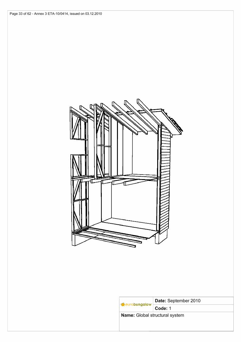
Annex 1 – Configuration of main assembled component s
1. External walls
There are three types of external walls depending on the external lining used. In all cases a timber cladding is used in the internal lining. Types of external lining:
• timber cladding;
• Werzalit© Selekta cladding;
• Werzalit© Siding cladding;
Werzalit© profiles are made of wood particles, impregnated with resins, and with a acrylic based decorative paint on the visible surface.
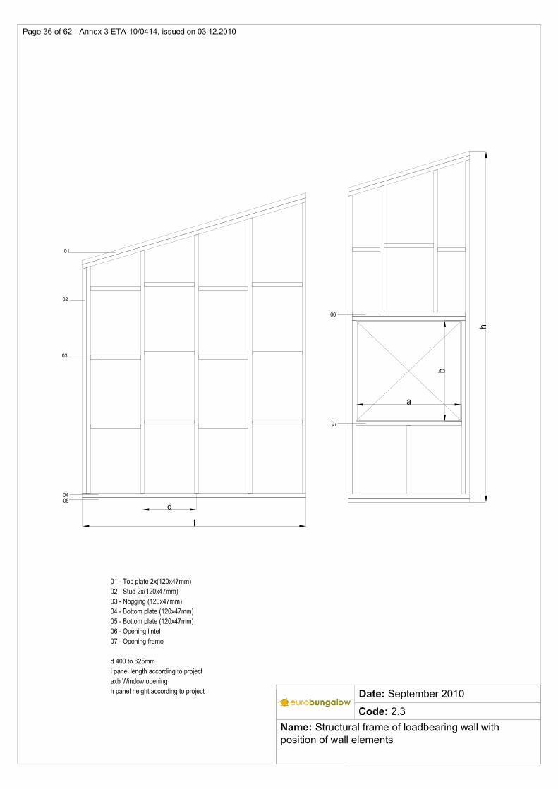
External walls are manufactured as prefabricated two-dimensional structural timber frames supplemented with materials on site. The dimensions of studs and noggins are always 120x47 mm. Spacing between studs axis in a timber frame oscillates in the range between 400 and 625 mm, it is possible to reduce the spacing below 400 mm if is necessary. Maximum height is 2.700 mm. The width of each prefabricated frame depends on the specific design with a maximum of 5.050 mm. Dimensions of bottom plate and top plate are 120x47 mm. Distance between noggins axis oscillates in the range between 700 and 1000 mm.
Thermal insulation and internal and external timber cladding are attached to the timber frame during the manufacturing process in the factory.
Waterproofing membrane, external timber cladding and Werzalit© are materials supplemented in site.
Glued laminated timber joists of suspended floors and roofs sit on doubled top plate of external and loadbearing internal walls.
Lintels and sidestuds for openings are designed case by case.
The following figures are not exhaustive. The complete list of configuration is in annex 3.
Page 20 of 62 ETA-10/0414, issued on 03.12.2010
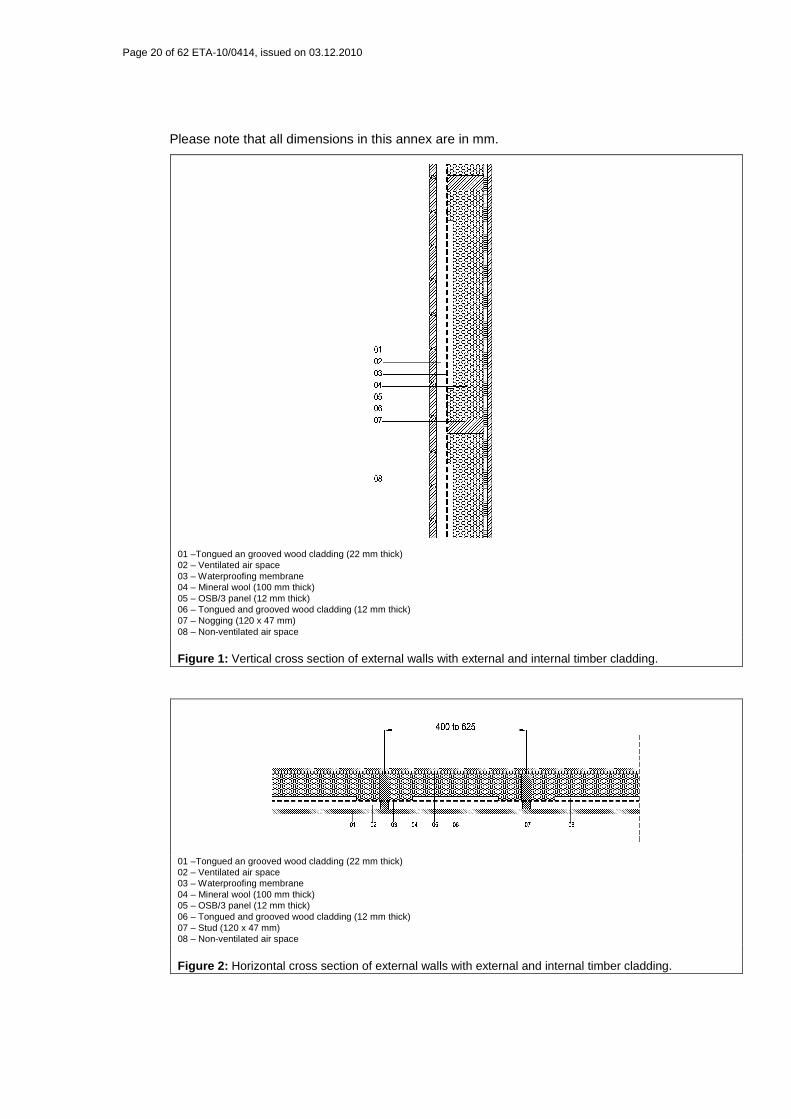
Please note that all dimensions in this annex are in mm.
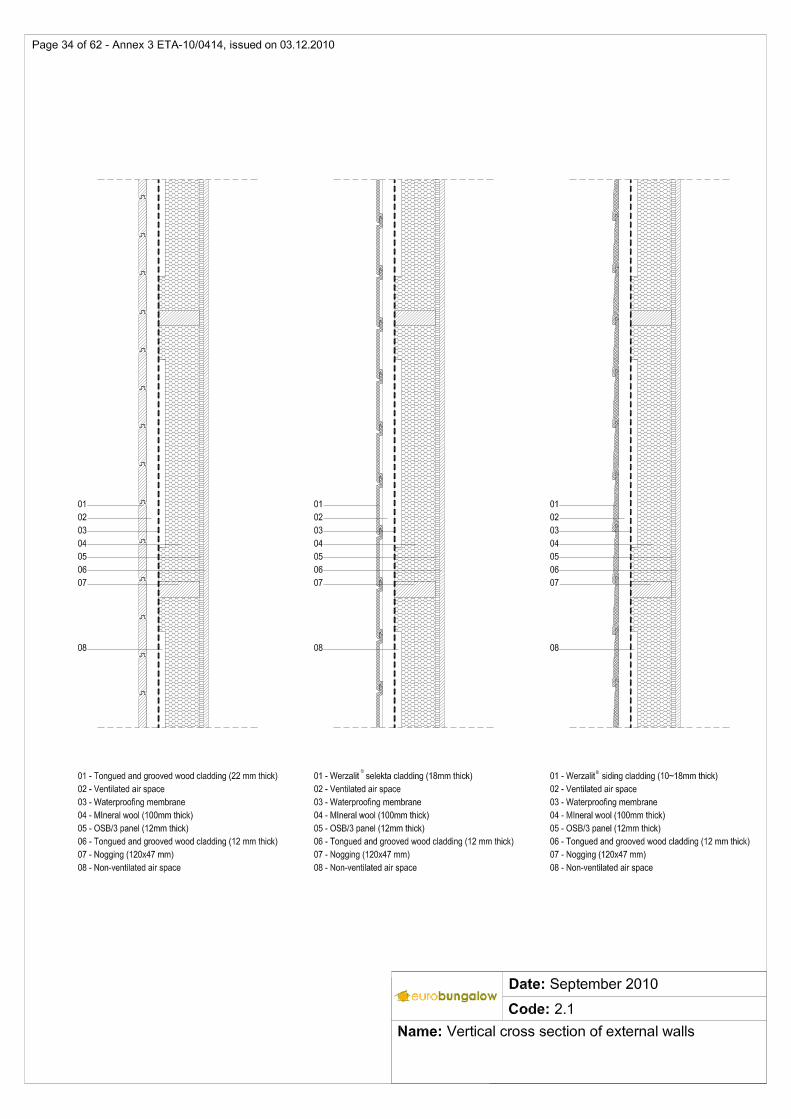
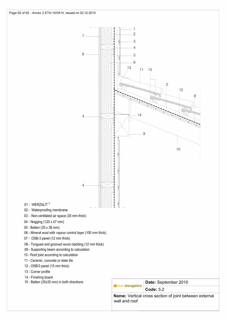
01 –Tongued an grooved wood cladding (22 mm thick) 02 – Ventilated air space 03 – Waterproofing membrane 04 – Mineral wool (100 mm thick) 05 – OSB/3 panel (12 mm thick) 06 – Tongued and grooved wood cladding (12 mm thick) 07 – Nogging (120 x 47 mm) 08 – Non-ventilated air space
Figure 1: Vertical cross section of external walls with external and internal timber cladding.
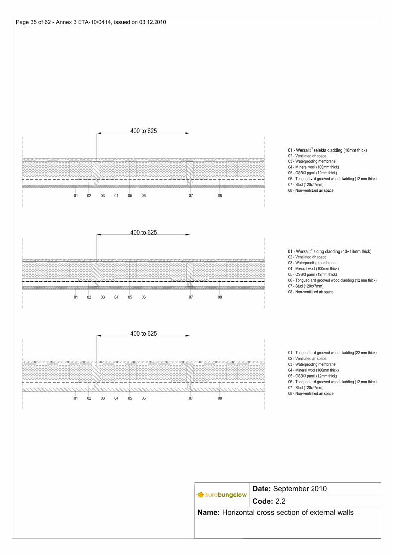
01 –Tongued an grooved wood cladding (22 mm thick) 02 – Ventilated air space 03 – Waterproofing membrane 04 – Mineral wool (100 mm thick) 05 – OSB/3 panel (12 mm thick) 06 – Tongued and grooved wood cladding (12 mm thick) 07 – Stud (120 x 47 mm) 08 – Non-ventilated air space
Figure 2: Horizontal cross section of external walls with external and internal timber cladding.
Page 21 of 62 ETA-10/0414, issued on 03.12.2010
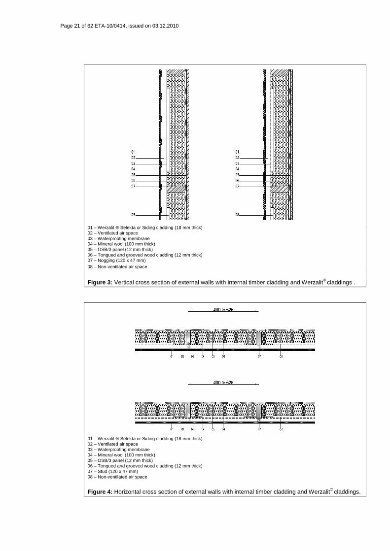
01 – Werzalit ® Selekta or Siding cladding (18 mm thick) 02 – Ventilated air space 03 – Waterproofing membrane 04 – Mineral wool (100 mm thick) 05 – OSB/3 panel (12 mm thick) 06 – Tongued and grooved wood cladding (12 mm thick) 07 – Nogging (120 x 47 mm) 08 – Non-ventilated air space
Figure 3: Vertical cross section of external walls with internal timber cladding and Werzalit© claddings .
01 – Werzalit ® Selekta or Siding cladding (18 mm thick) 02 – Ventilated air space 03 – Waterproofing membrane 04 – Mineral wool (100 mm thick) 05 – OSB/3 panel (12 mm thick) 06 – Tongued and grooved wood cladding (12 mm thick) 07 – Stud (120 x 47 mm) 08 – Non-ventilated air space
Figure 4: Horizontal cross section of external walls with internal timber cladding and Werzalit© claddings.
Page 22 of 62 ETA-10/0414, issued on 03.12.2010
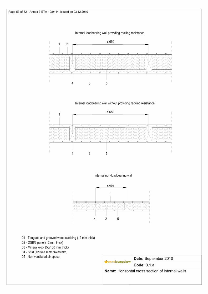
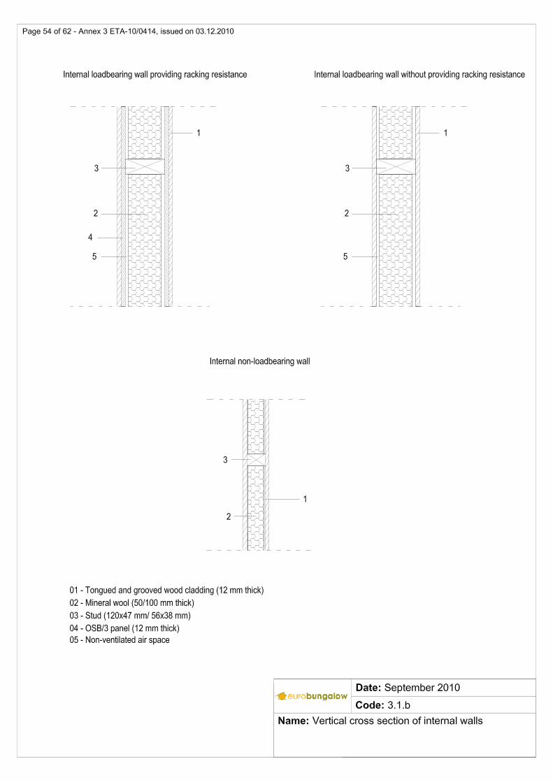
2. Internal walls
There are two types of internal walls: loadbearing and non-loadbearing internal walls.
Studs and noggins of 120 x 47 mm are used for loadbearing internal walls, while the 56 x 38 mm ones are used for the non-loadbearing internal walls.
In both cases internal walls are manufactured as prefabricated two-dimensional structural timber frames supplemented with materials in site.
The dimensions of studs and noggins in internal timber frames follow the same rules for external walls. Differences between external and internal walls are located in claddings, linings and in thermal insulation.
Thermal insulation of 100 mm mineral wool is used for loadbearing internal walls while 50 mm mineral wool is used for non-loadbearing internal walls. In both cases internal lining in timber cladding 12 mm thick is used.
Page 23 of 62 ETA-10/0414, issued on 03.12.2010
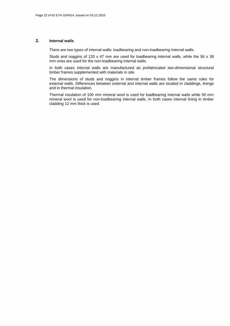
01 –Tongued an grooved wood cladding (22 mm thick) 02 – OSB/3 panel (12 mm thick) 03 – Mineral wool (100 mm thick) 04 – Stud (120 x 47 mm) 05 – Non-ventilated air space
Figure 5. Horizontal cross section of loadbearing internal walls.
01 –Tongued an grooved wood cladding (22 mm thick) 02 – OSB/3 panel (12 mm thick) 03 – Mineral wool (50 mm thick) 04 – Stud (56 x 38 mm) 05 – Non-ventilated air space
Figure 6. Horizontal cross section of non-loadbearing internal walls.
Page 24 of 62 ETA-10/0414, issued on 03.12.2010
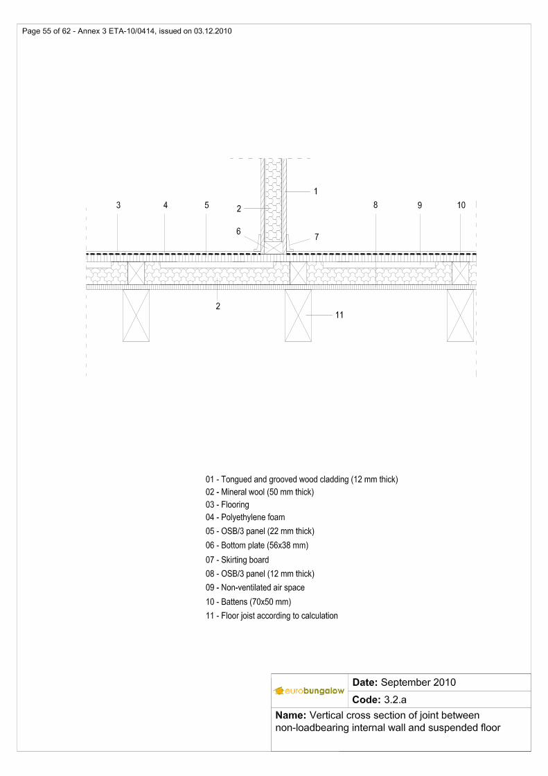
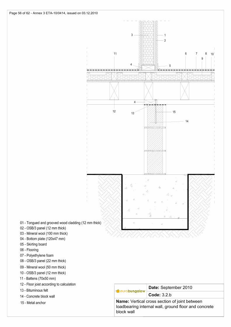
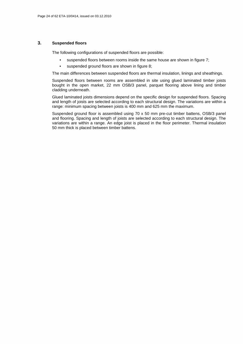
3. Suspended floors
The following configurations of suspended floors are possible:
• suspended floors between rooms inside the same house are shown in figure 7;
• suspended ground floors are shown in figure 8;
The main differences between suspended floors are thermal insulation, linings and sheathings.
Suspended floors between rooms are assembled in site using glued laminated timber joists bought in the open market, 22 mm OSB/3 panel, parquet flooring above lining and timber cladding underneath.
Glued laminated joists dimensions depend on the specific design for suspended floors. Spacing and length of joists are selected according to each structural design. The variations are within a range: minimum spacing between joists is 400 mm and 625 mm the maximum.
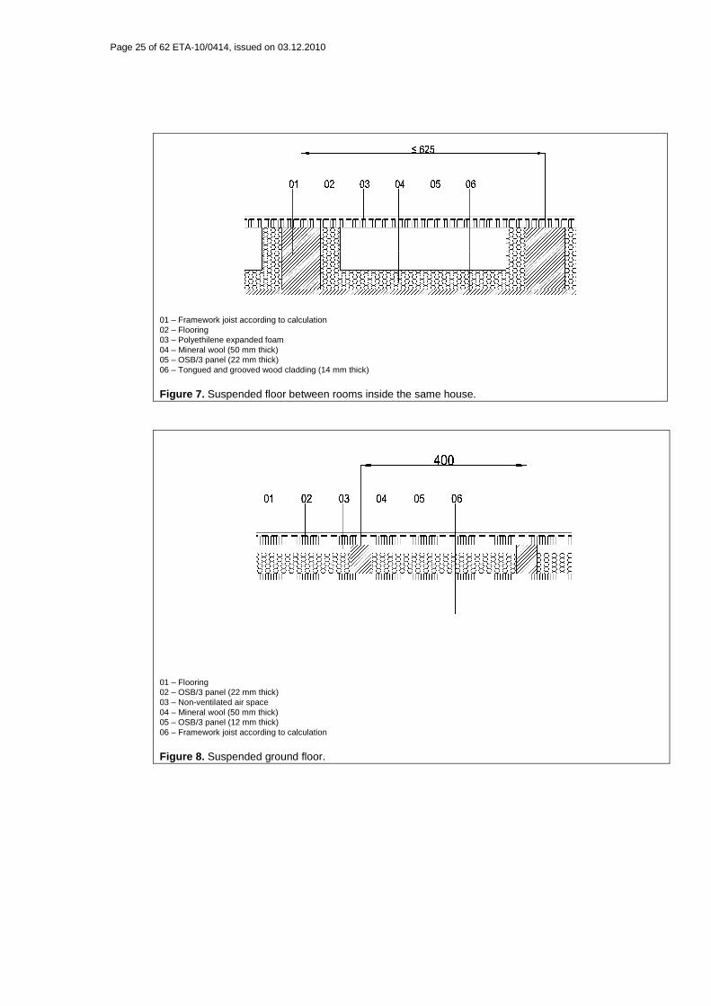
Suspended ground floor is assembled using 70 x 50 mm pre-cut timber battens, OSB/3 panel and flooring. Spacing and length of joists are selected according to each structural design. The variations are within a range. An edge joist is placed in the floor perimeter. Thermal insulation 50 mm thick is placed between timber battens.
Page 25 of 62 ETA-10/0414, issued on 03.12.2010
01 – Framework joist according to calculation 02 – Flooring 03 – Polyethilene expanded foam 04 – Mineral wool (50 mm thick) 05 – OSB/3 panel (22 mm thick) 06 – Tongued and grooved wood cladding (14 mm thick)
Figure 7. Suspended floor between rooms inside the same house.
01 – Flooring 02 – OSB/3 panel (22 mm thick) 03 – Non-ventilated air space 04 – Mineral wool (50 mm thick) 05 – OSB/3 panel (12 mm thick) 06 – Framework joist according to calculation
Figure 8. Suspended ground floor.
Page 26 of 62 ETA-10/0414, issued on 03.12.2010
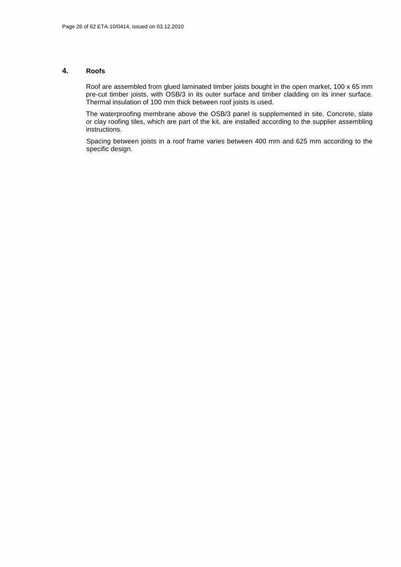
4. Roofs
Roof are assembled from glued laminated timber joists bought in the open market, 100 x 65 mm pre-cut timber joists, with OSB/3 in its outer surface and timber cladding on its inner surface. Thermal insulation of 100 mm thick between roof joists is used.
The waterproofing membrane above the OSB/3 panel is supplemented in site. Concrete, slate or clay roofing tiles, which are part of the kit, are installed according to the supplier assembling instructions.
Spacing between joists in a roof frame varies between 400 mm and 625 mm according to the specific design.
Page 27 of 62 ETA-10/0414, issued on 03.12.2010
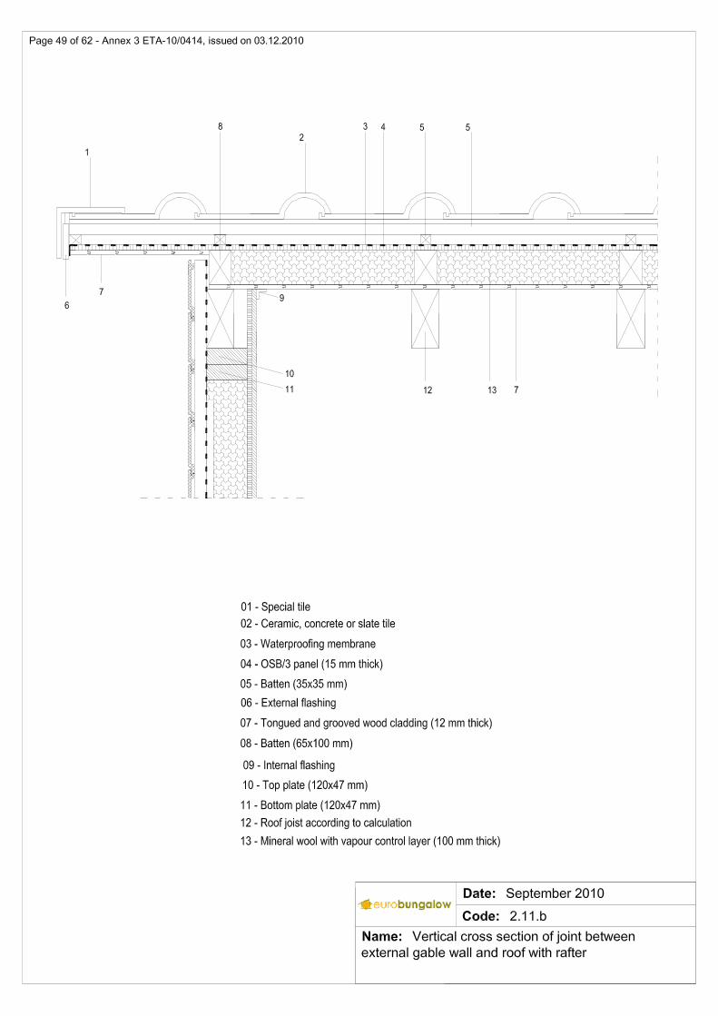
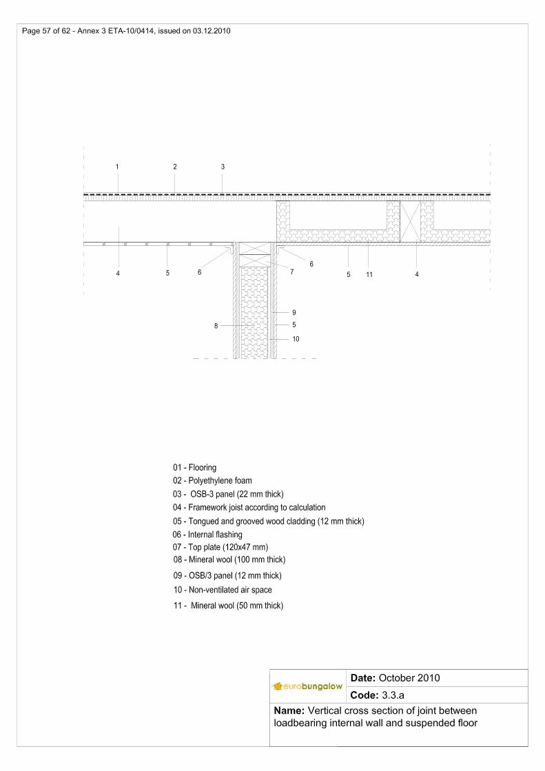
01 – Special tile 02 – Ceramic, concrete or slate tile 03 – Waterproofing membrane 04 – OSB/3 panel (15 mm thick) 05 – Batten (35 x 35 mm) 06 – Exterior flashing 07 – Tongued and grooved wood cladding (12 mm thick) 08 – Batten (65 x 100 mm) 09 – Internal flashing 10 – Top plate (120 x 47 mm) 11 – Bottom plate (120 x 47 mm) 12 – Roof joist according to calculation 13 – Mineral wool with vapour control layer (100 mm thick)
Figure 9. Vertical cross section of the roof
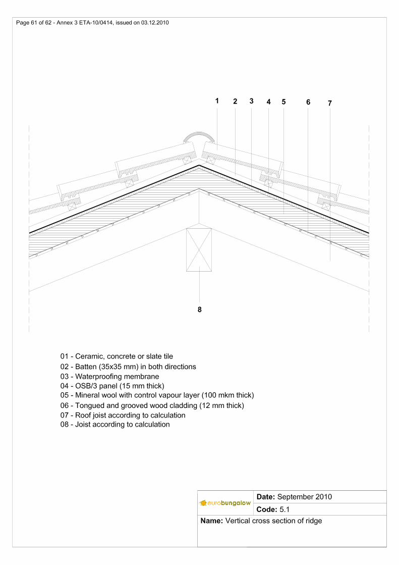
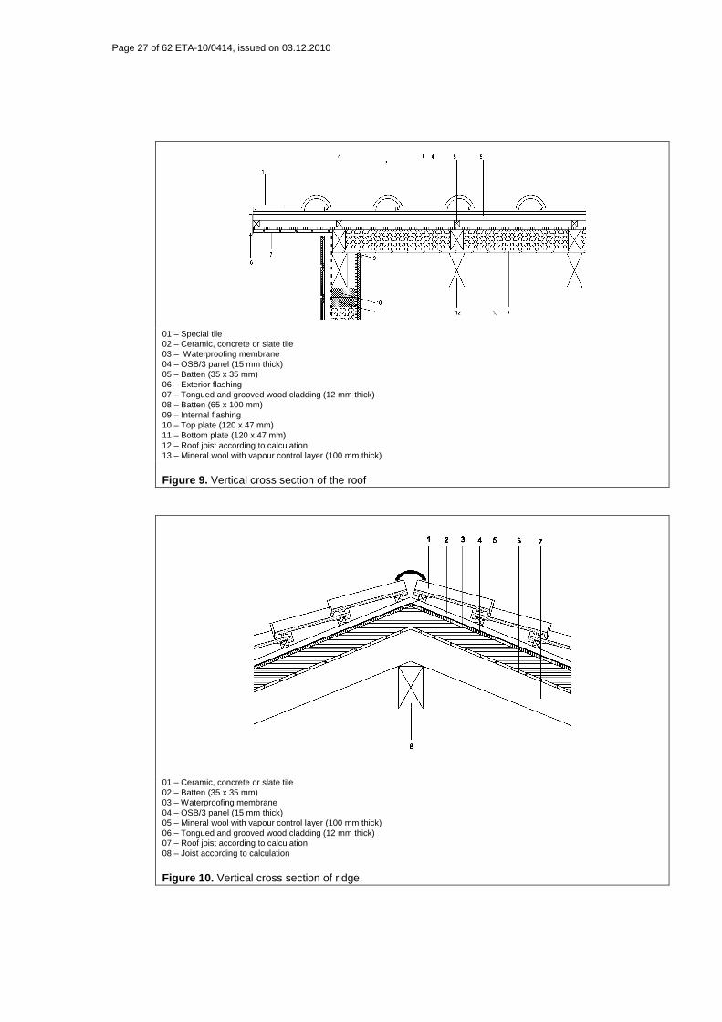
01 – Ceramic, concrete or slate tile 02 – Batten (35 x 35 mm) 03 – Waterproofing membrane 04 – OSB/3 panel (15 mm thick) 05 – Mineral wool with vapour control layer (100 mm thick) 06 – Tongued and grooved wood cladding (12 mm thick) 07 – Roof joist according to calculation 08 – Joist according to calculation
Figure 10. Vertical cross section of ridge.
Page 28 of 62 ETA-10/0414, issued on 03.12.2010
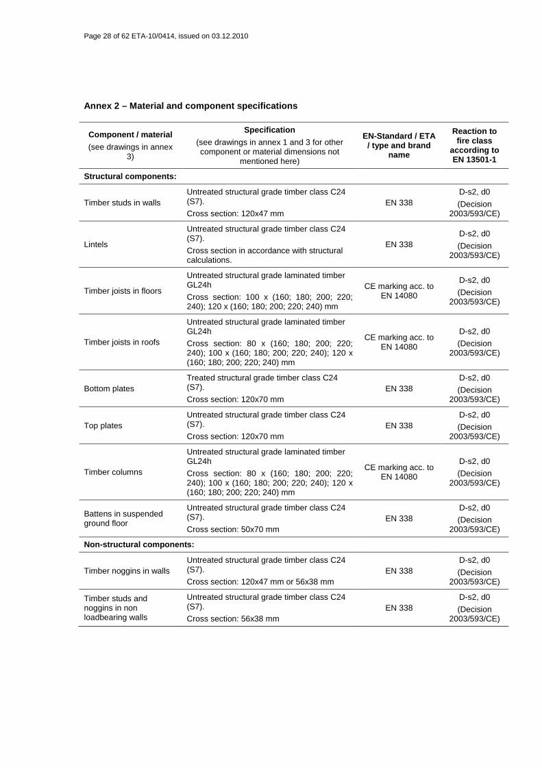
Annex 2 – Material and component specifications
Component / material
(see drawings in annex 3)
Specification
(see drawings in annex 1 and 3 for other component or material dimensions not
mentioned here)
EN-Standard / ETA / type and brand
name
Reaction to fire class
according to EN 13501-1
Structural components:
Timber studs in walls Untreated structural grade timber class C24 (S7).
Cross section: 120x47 mm EN 338
D-s2, d0
(Decision 2003/593/CE)
Lintels
Untreated structural grade timber class C24 (S7).
Cross section in accordance with structural calculations.
EN 338 D-s2, d0
(Decision 2003/593/CE)
Timber joists in floors
Untreated structural grade laminated timber GL24h
Cross section: 100 x (160; 180; 200; 220; 240); 120 x (160; 180; 200; 220; 240) mm
CE marking acc. to EN 14080
D-s2, d0
(Decision 2003/593/CE)
Timber joists in roofs
Untreated structural grade laminated timber GL24h
Cross section: 80 x (160; 180; 200; 220; 240); 100 x (160; 180; 200; 220; 240); 120 x (160; 180; 200; 220; 240) mm
CE marking acc. to EN 14080
D-s2, d0
(Decision 2003/593/CE)
Bottom plates Treated structural grade timber class C24 (S7).
Cross section: 120x70 mm EN 338
D-s2, d0
(Decision 2003/593/CE)
Top plates Untreated structural grade timber class C24 (S7).
Cross section: 120x70 mm EN 338
D-s2, d0
(Decision 2003/593/CE)
Timber columns
Untreated structural grade laminated timber GL24h
Cross section: 80 x (160; 180; 200; 220; 240); 100 x (160; 180; 200; 220; 240); 120 x (160; 180; 200; 220; 240) mm
CE marking acc. to EN 14080
D-s2, d0
(Decision 2003/593/CE)
Battens in suspended ground floor
Untreated structural grade timber class C24 (S7).
Cross section: 50x70 mm EN 338
D-s2, d0
(Decision 2003/593/CE)
Non-structural components:
Timber noggins in walls Untreated structural grade timber class C24 (S7).
Cross section: 120x47 mm or 56x38 mm EN 338
D-s2, d0
(Decision 2003/593/CE)
Timber studs and noggins in non loadbearing walls
Untreated structural grade timber class C24 (S7).
Cross section: 56x38 mm EN 338
D-s2, d0
(Decision 2003/593/CE)
Page 29 of 62 ETA-10/0414, issued on 03.12.2010
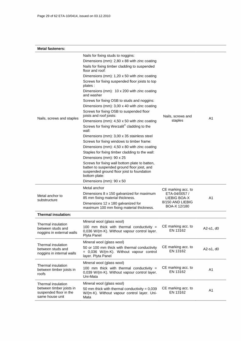
Metal fasteners:
Nails, screws and staples
Nails for fixing studs to noggins:
Dimensions (mm): 2,80 x 88 with zinc coating
Nails for fixing timber cladding to suspended floor and roof:
Dimensions (mm): 1,20 x 50 with zinc coating
Screws for fixing suspended floor joists to top plates :
Dimensions (mm): 10 x 200 with zinc coating and washer
Screws for fixing OSB to studs and noggins:
Dimensions (mm): 3,00 x 40 with zinc coating
Screws for fixing OSB to suspended floor joists and roof joists:
Dimensions (mm): 4,50 x 50 with zinc coating
Screws for fixing Werzalit© cladding to the wall:
Dimensions (mm): 3,00 x 35 stainless steel
Screws for fixing windows to timber frame:
Dimensions (mm): 4,50 x 80 with zinc coating
Staples for fixing timber cladding to the wall:
Dimensions (mm): 90 x 25
Screws for fixing wall bottom plate to batten, batten to suspended ground floor joist, and suspended ground floor joist to foundation bottom plate:
Dimensions (mm): 90 x 50
Nails, screws and staples A1
Metal anchor to substructure
Metal anchor
Dimensions 8 x 150 galvanized for maximum 85 mm fixing material thickness.
Dimensions 12 x 180 galvanized for maximum 100 mm fixing material thickness.
CE marking acc. to ETA-04/0057 / LIEBIG BOA-X
8/150 AND LIEBIG BOA-X 12/180
A1
Thermal insulation:
Thermal insulation between studs and noggins in external walls
Mineral wool (glass wool)
100 mm thick with thermal conductivity = 0,036 W/(m·K). Without vapour control layer. Plyta Panel
CE marking acc. to EN 13162 A2-s1, d0
Thermal insulation between studs and noggins in internal walls
Mineral wool (glass wool)
50 or 100 mm thick with thermal conductivity = 0,036 W/(m·K). Without vapour control layer. Plyta Panel
CE marking acc. to EN 13162 A2-s1, d0
Thermal insulation between timber joists in roofs
Mineral wool (glass wool)
100 mm thick with thermal conductivity = 0,039 W/(m·K). Without vapour control layer. Uni-Mata
CE marking acc. to EN 13162
A1
Thermal insulation between timber joists in suspended floor in the same house unit
Mineral wool (glass wool)
50 mm thick with thermal conductivity = 0,039 W/(m·K). Without vapour control layer. Uni-Mata
CE marking acc. to EN 13162 A1
Page 30 of 62 ETA-10/0414, issued on 03.12.2010
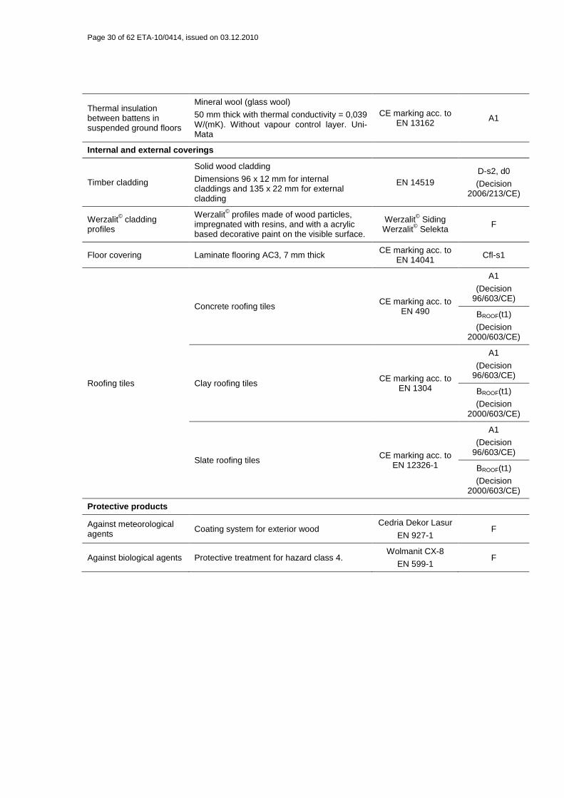
Thermal insulation between battens in suspended ground floors
Mineral wool (glass wool)
50 mm thick with thermal conductivity = 0,039 W/(mK). Without vapour control layer. Uni-Mata
CE marking acc. to EN 13162 A1
Internal and external coverings
Timber cladding
Solid wood cladding
Dimensions 96 x 12 mm for internal claddings and 135 x 22 mm for external cladding
EN 14519 D-s2, d0
(Decision 2006/213/CE)
Werzalit© cladding profiles
Werzalit© profiles made of wood particles, impregnated with resins, and with a acrylic based decorative paint on the visible surface.
Werzalit© Siding Werzalit© Selekta F
Floor covering Laminate flooring AC3, 7 mm thick CE marking acc. to EN 14041 Cfl-s1
Roofing tiles
Concrete roofing tiles CE marking acc. to EN 490
A1
(Decision 96/603/CE)
BROOF(t1)
(Decision 2000/603/CE)
Clay roofing tiles CE marking acc. to EN 1304
A1
(Decision 96/603/CE)
BROOF(t1)
(Decision 2000/603/CE)
Slate roofing tiles CE marking acc. to EN 12326-1
A1
(Decision 96/603/CE)
BROOF(t1)
(Decision 2000/603/CE)
Protective products
Against meteorological agents Coating system for exterior wood
Cedria Dekor Lasur
EN 927-1 F
Against biological agents Protective treatment for hazard class 4. Wolmanit CX-8
EN 599-1 F
Page 31 of 62 ETA-10/0414, issued on 03.12.2010
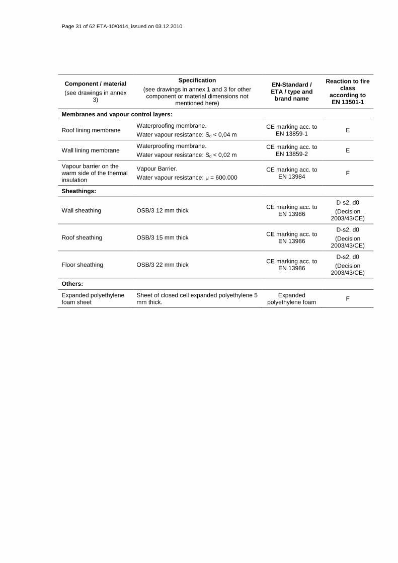
Component / material
(see drawings in annex 3)
Specification
(see drawings in annex 1 and 3 for other component or material dimensions not
mentioned here)
EN-Standard / ETA / type and
brand name
Reaction to fire class
according to EN 13501-1
Membranes and vapour control layers:
Roof lining membrane Waterproofing membrane.
Water vapour resistance: Sd < 0,04 m CE marking acc. to
EN 13859-1 E
Wall lining membrane Waterproofing membrane.
Water vapour resistance: Sd < 0,02 m CE marking acc. to
EN 13859-2 E
Vapour barrier on the warm side of the thermal insulation
Vapour Barrier.
Water vapour resistance: µ = 600.000 CE marking acc. to
EN 13984 F
Sheathings:
Wall sheathing OSB/3 12 mm thick CE marking acc. to
EN 13986
D-s2, d0
(Decision 2003/43/CE)
Roof sheathing OSB/3 15 mm thick CE marking acc. to EN 13986
D-s2, d0
(Decision 2003/43/CE)
Floor sheathing OSB/3 22 mm thick CE marking acc. to EN 13986
D-s2, d0
(Decision 2003/43/CE)
Others:
Expanded polyethylene foam sheet
Sheet of closed cell expanded polyethylene 5 mm thick.
Expanded polyethylene foam F
Page 32 of 62 ETA-10/0414, issued on 03.12.2010
Annex 3 – Essential construction details
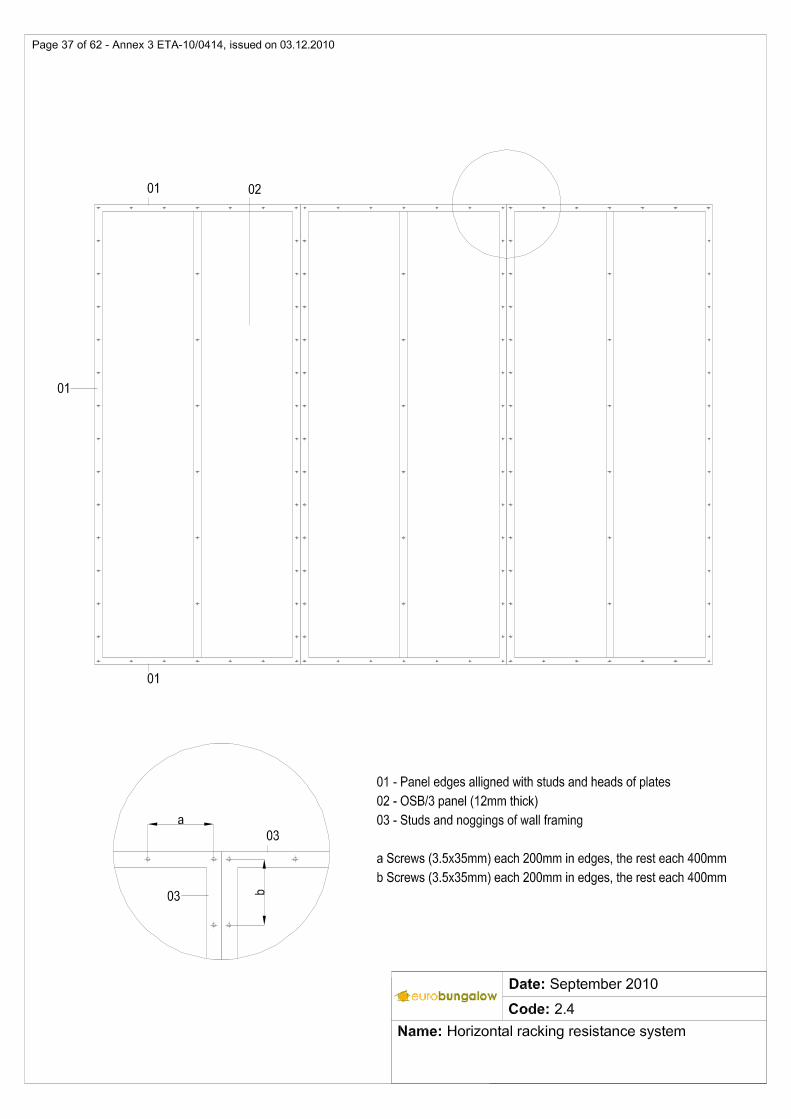
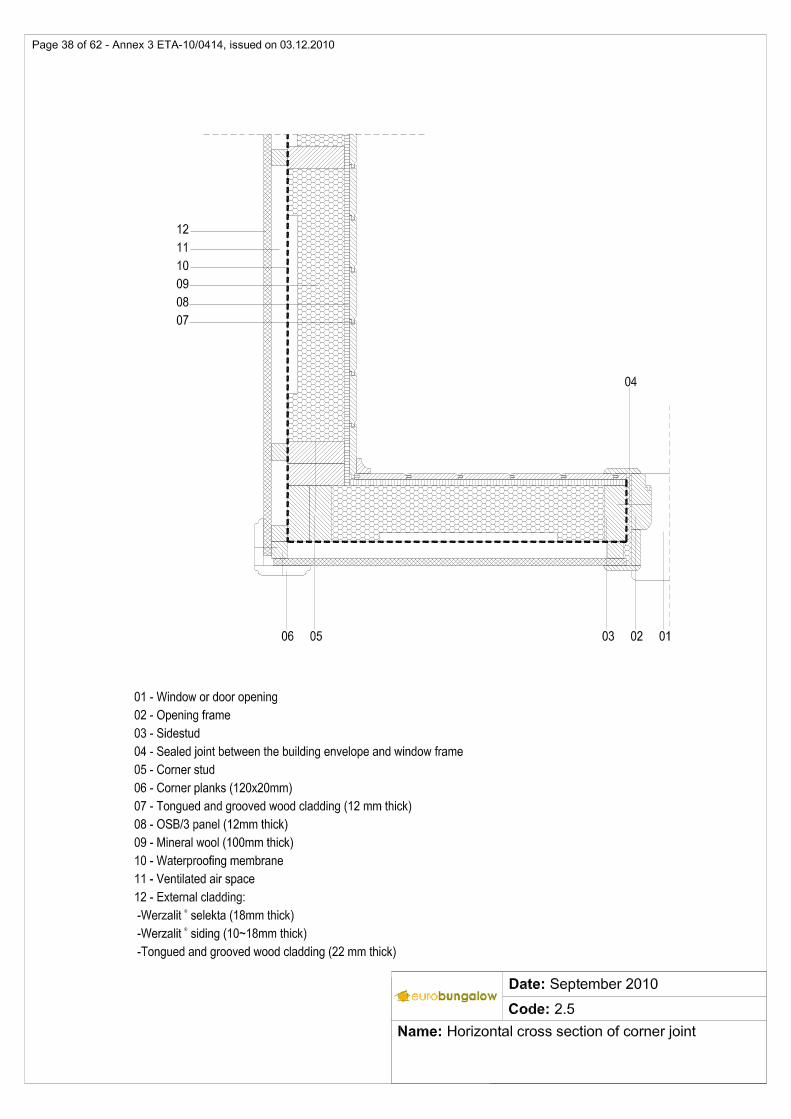
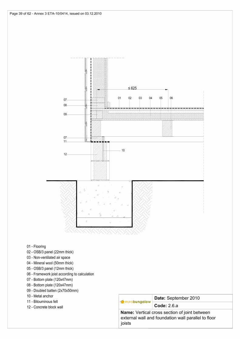
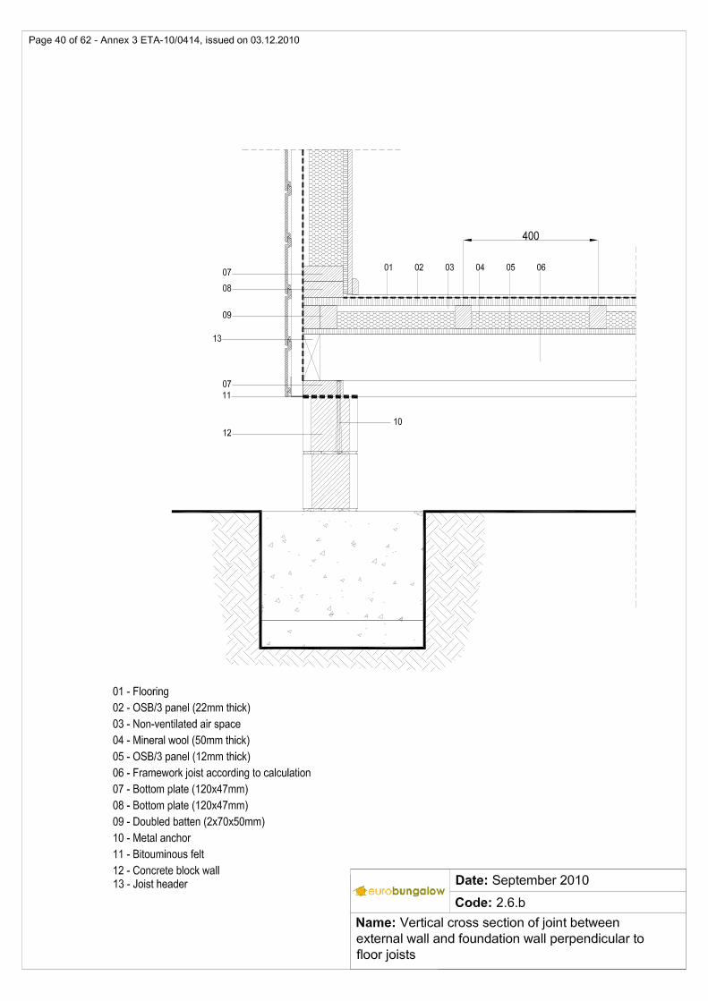
TABLE OF CONTENTS 1 Global structural system ........................ .................................................................................. 33 2 External walls .................................. .......................................................................................... 34 2.1 Vertical cross section of external walls ....................................................................................... 34 2.2 Horizontal cross section of external walls ................................................................................... 35 2.3 Structural frame of loadbearing wall with positions of wall elements .......................................... 36 2.4 Horizontal racking resistance system ......................................................................................... 37 2.5 Horizontal cross section of corner joint ....................................................................................... 38 2.6.a Vertical cross section of joint between external wall and foundation wall parallel to floor joists 39 2.6.b Vertical cross section of joint between external wall and foundation wall perpendicular to floor
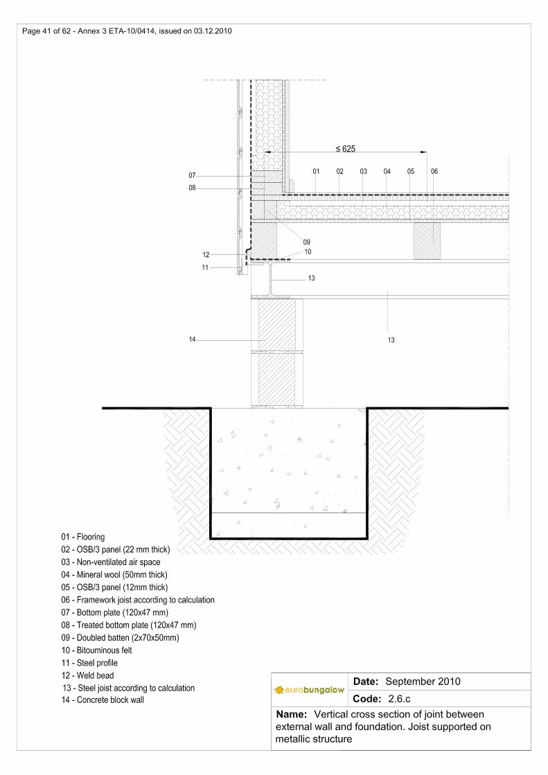
joists ............................................................................................................................................ 40 2.6.c Vertical cross section of joint between external wall and foundation. Joist supported on metallic
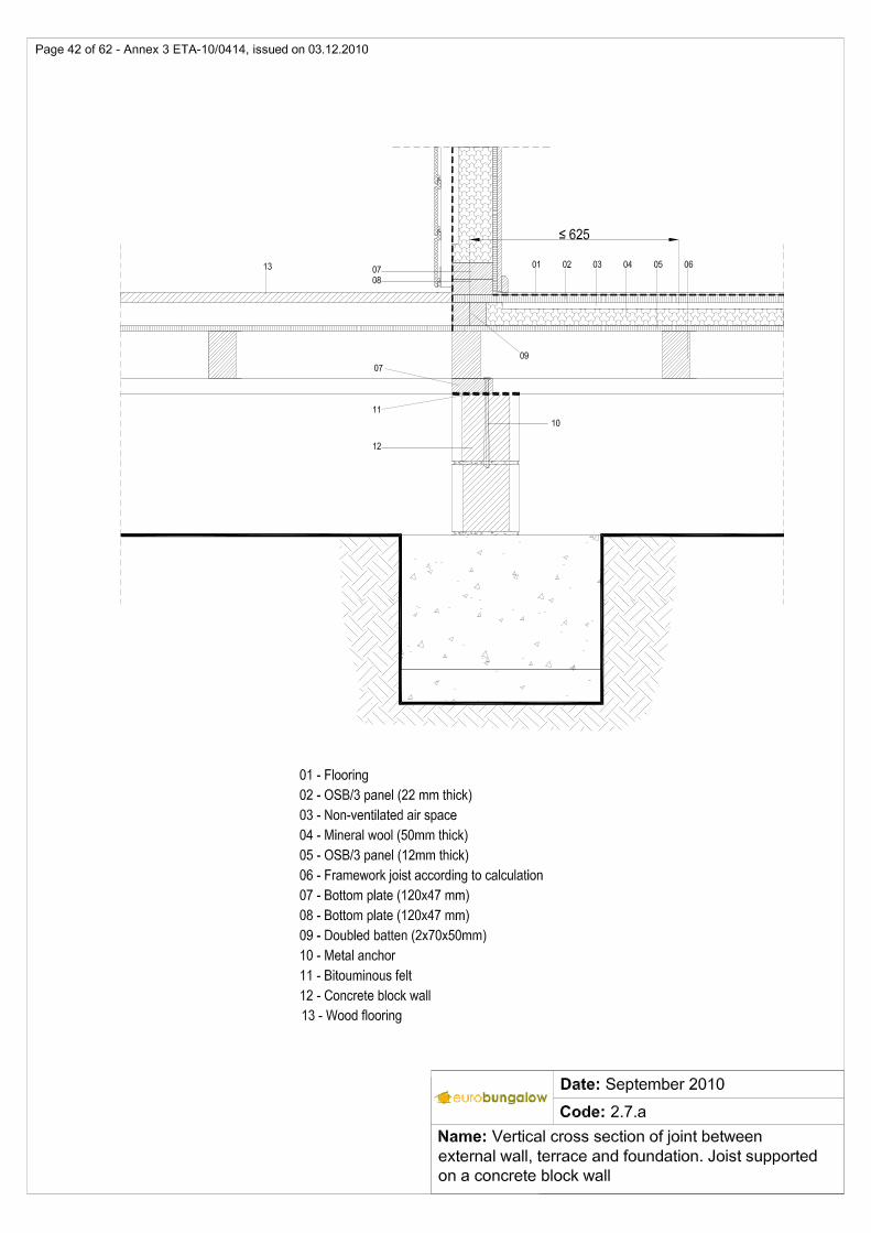
structure ...................................................................................................................................... 41 2.7.a Vertical cross section of joint between external wall, terrace and foundation. Joist supported on
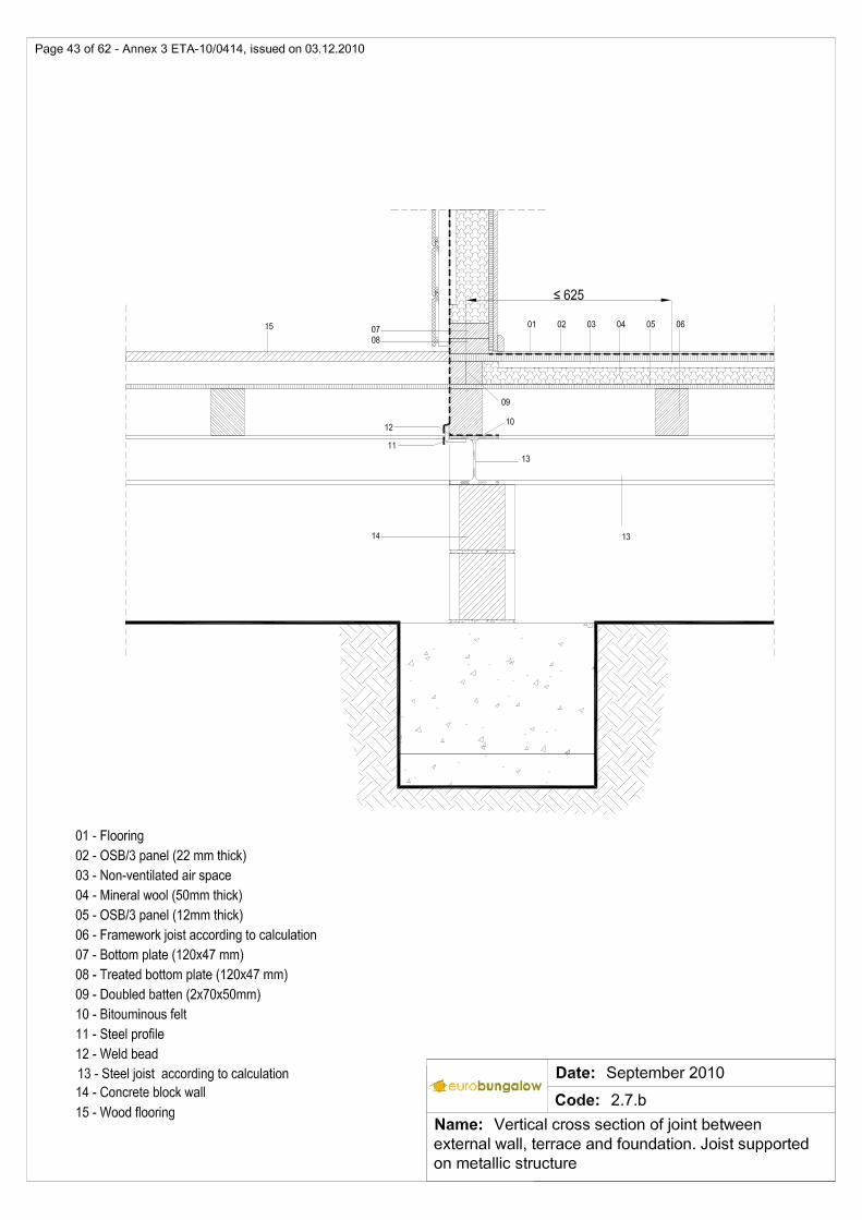
a concrete block wall .................................................................................................................. 42 2.7.b Vertical cross section of joint between external wall, terrace and foundation. Joist supported on
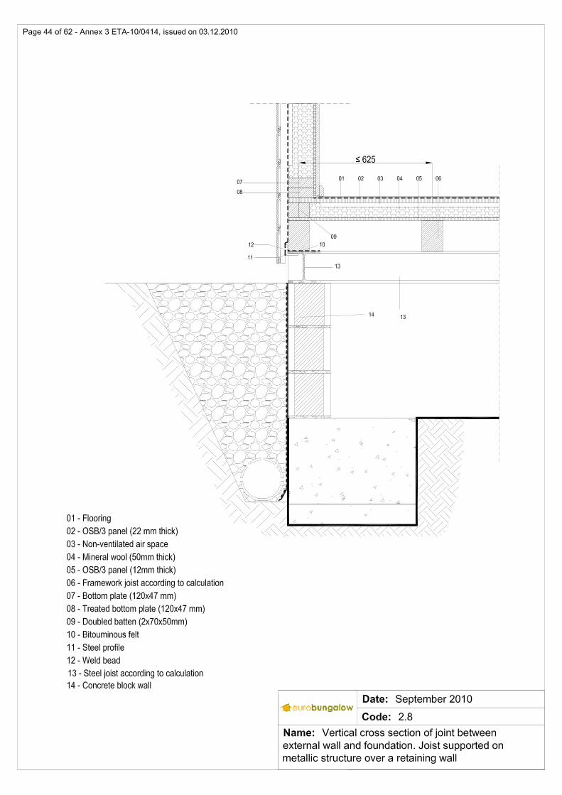
metallic structure ......................................................................................................................... 43 2.8 Vertical cross section of joint between external wall and foundation. Joist supported on metallic
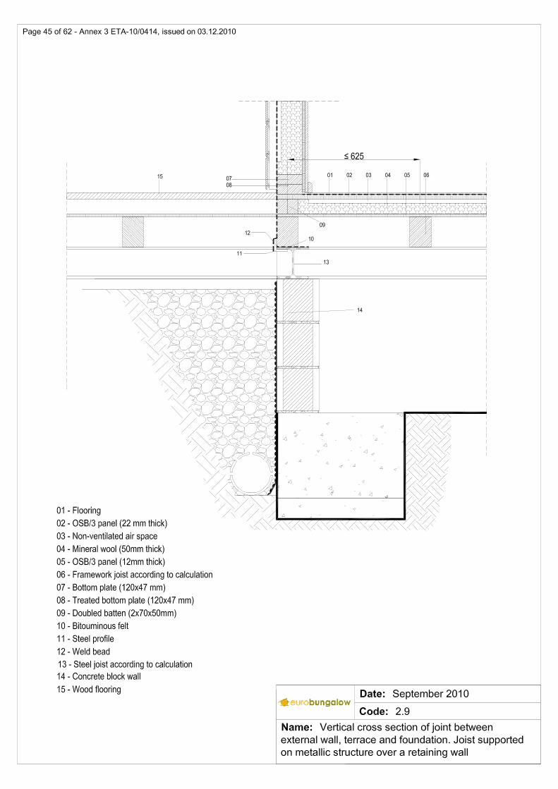
structure over a retaining wall ..................................................................................................... 44 2.9 Vertical cross section of joint between external wall, terrace and foundation. Joist supported on
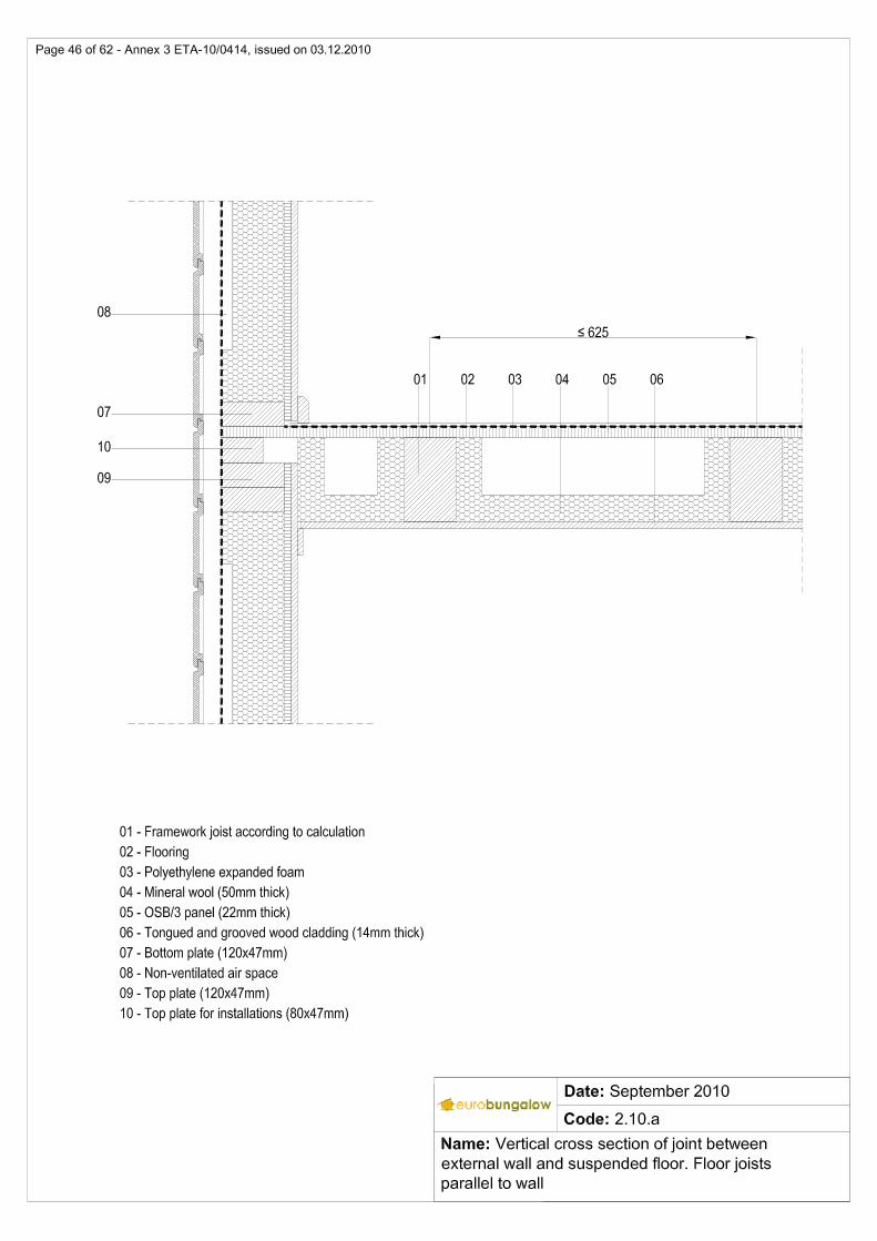
a metallic structure over a retaining wall .................................................................................... 45 2.10.a Vertical cross section of joint between external wall and suspended floor. Floor joists
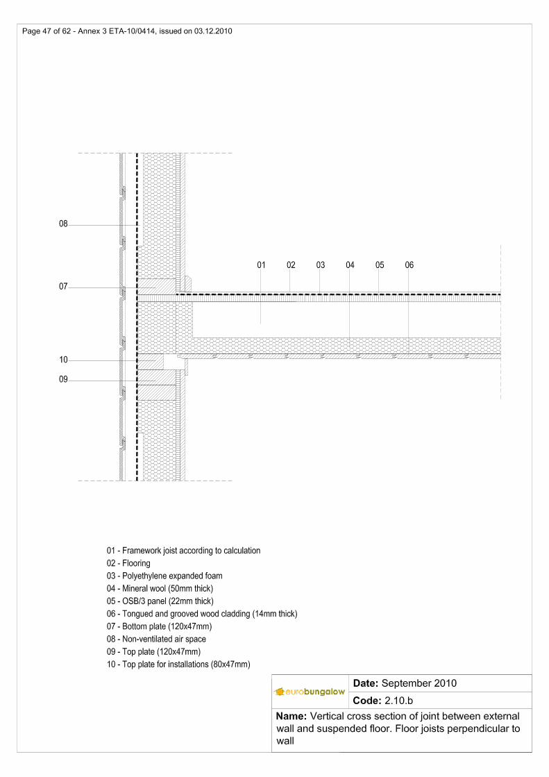
parallel to wall ............................................................................................................................. 46 2.10.b Vertical cross section of joint between external wall and suspended floor. Floor joists
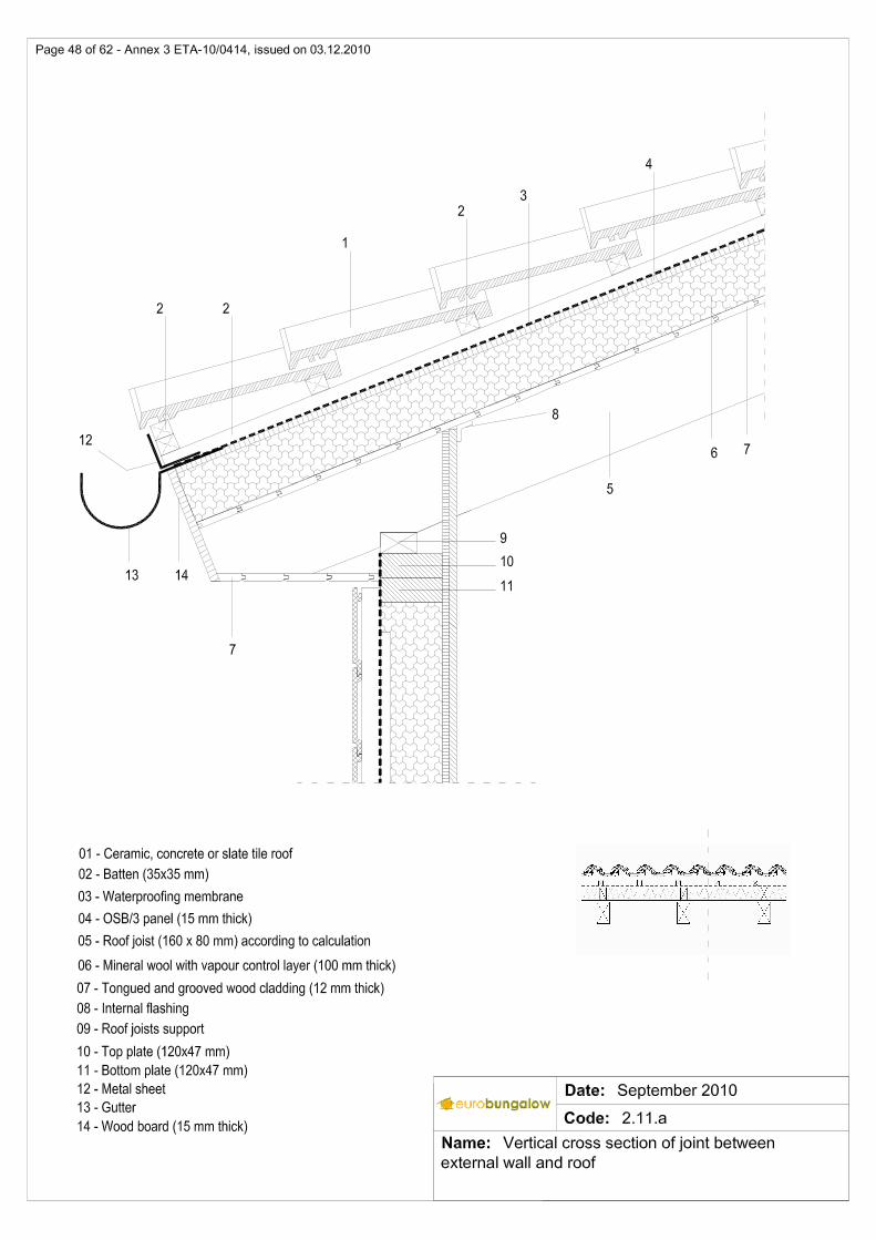
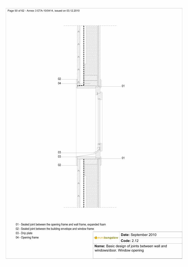
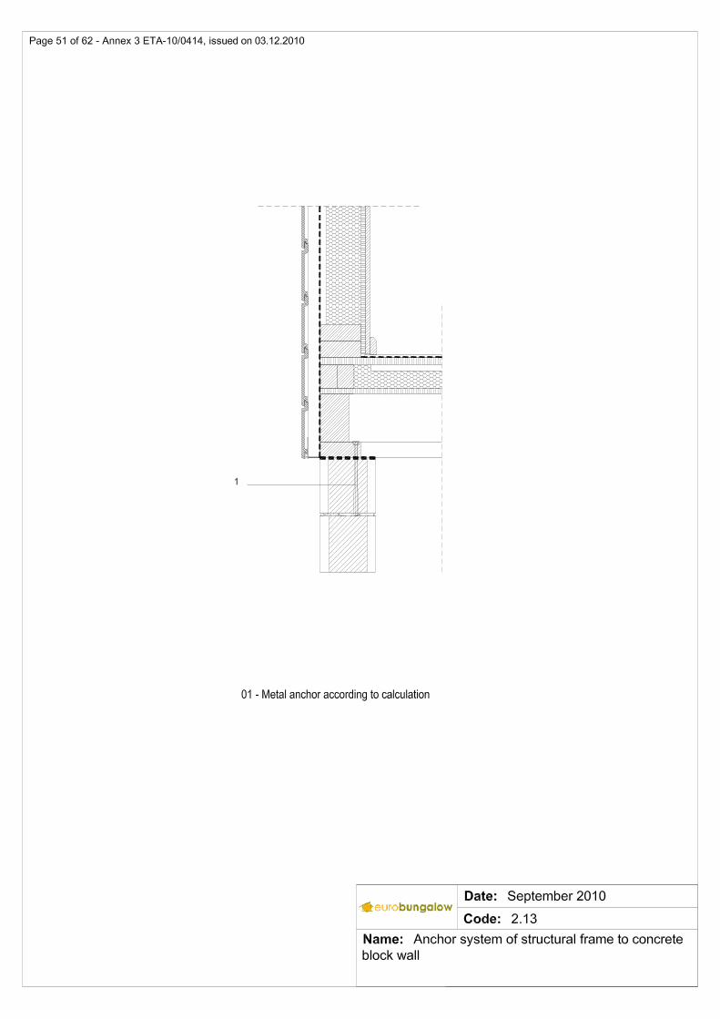
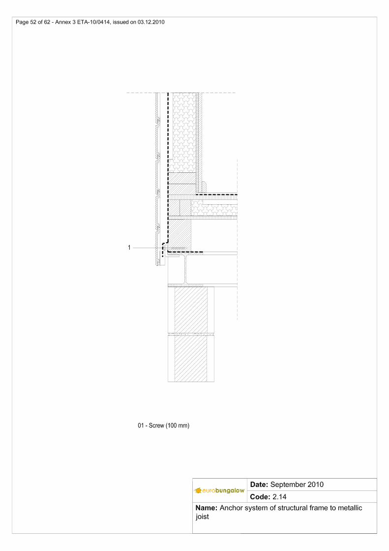
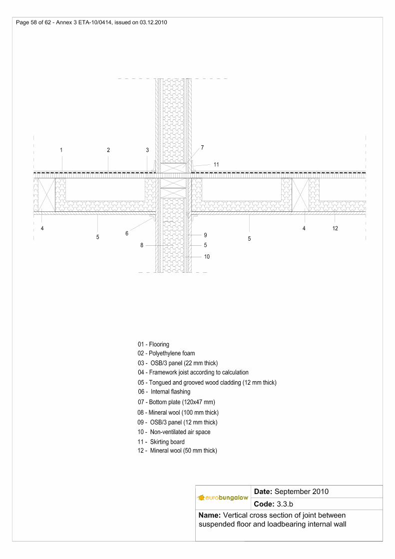
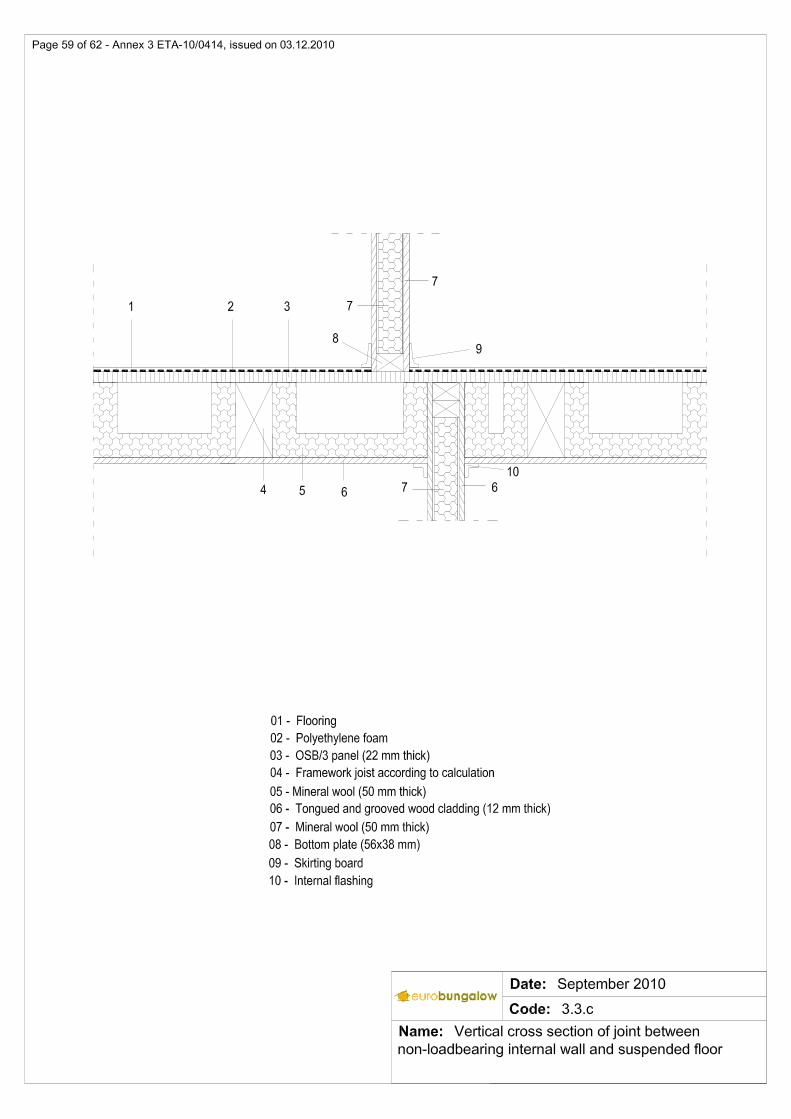
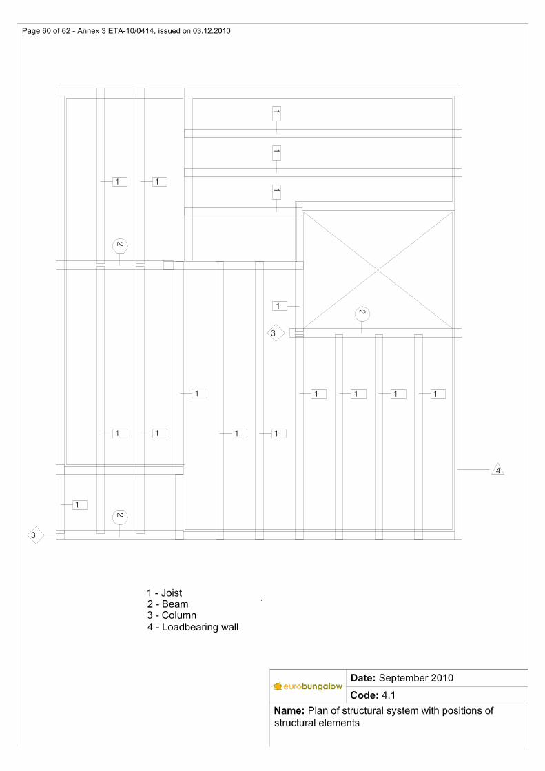
perpendicular to wall ................................................................................................................... 47 2.11.a Vertical cross section of joint between external wall and roof .................................................... 48 2.11.b. Vertical cross section of joint between external gable wall and roof with rafter ......................... 49 2.12 Basic design of joints between wall and windows/door. Window opening ................................. 50 2.13 Anchor system of structural frame to concrete block wall .......................................................... 51 2.14 Anchor system of structural frame to metallic joist ..................................................................... 52 3 Internal walls .................................. ........................................................................................... 53 3.1.a Horizontal cross section of internal walls .................................................................................... 53 3.1.b Vertical cross section of internal walls ........................................................................................ 54 3.2.a Vertical cross section of joint between non-loadbearing internal wall and suspended floor ...... 55 3.2.b Vertical cross section of joint between loadbearing internal wall, ground floor and
concrete block wall ..................................................................................................................... 56 3.3.a Vertical cross section of joint between loadbearing internal wall and suspended floor .............. 57 3.3.b Vertical cross section of joint between suspended floor and loadbearing internal wall .............. 58 3.3.c Vertical cross section of joint between non-loadbearing internal wall and suspended floor ...... 59 4 Suspended floors ................................ ...................................................................................... 60 4.1 Plan of structural system with positions of structural elements .................................................. 60 5 Roofs ........................................... ............................................................................................... 61 5.1 Vertical cross section of ridge ..................................................................................................... 61 5.2 Vertical cross section of joint between external wall and roof .................................................... 62