etops transit check 767-300 revision 19 transit check b767-300... · etops transit check as per...
TRANSCRIPT
ETOPS TRANSIT CHECK REVISION 19
767-300
Page 1 of 18
AMM Reference: D633T115 Latest Revision Doc Reference: ENG\LM\B767-300\ETOPS TRANSIT CHECK REVISION 19
Release date: 06 October 2016
A/C Registration:
Performed date:
Time UTC:
Performed by: Stamp:
ETOPS TRANSIT CHECK as per Operator Maintenance Program Ref. JAF/MP/B767 Latest revision. Before each ETOPS flight the ETOPS appropriately qualified staff must verify that the airplane is satisfactory for flight. Check is to be completed within 2-4 hours of ETOPS departure.
Item Task Related Documents
MAINT
1. SVC Zones: NRC NO YES, Number(s):
CHECK ON-BOARD DOCS FOR OPEN ENTRIES AND REQUIRED CORRECTIVE ACTION(S), RECORD SERVICINGS PERFORMED, MAINTENANCE FINDINGS AND/OR ACTIONS AND CHECK OUTSTANDING DEFERRED ITEMS.
1. Review AIRCRAFT TECHNICAL LOG and CABIN TECHNICAL LOG for reported discrepancies
2. Check ACCEPTABLE DEFERRED DEFECT SHEET and CABIN DEFERRED DEFECT SHEET
3. Verify EICAS status level messages and higher are resolved or ADD paper work is applied.
Item Task Related Documents
MAINT
2. SVC MP 79-309-01-01 AMM 12-13-01-613-001-002 MP 79-309-01-02 AMM 12-13-01-613-001-002 MP 49-021-00-01 AMM 12-13-04-613-001
Zones: NRC NO YES, Number(s):
CHECK OIL LEVEL OF LEFT / RIGHT ENGINE AND APU.
1. Verify the left engine oil level
a. If oil level >= 21 Quarts no action required.
b. If oil level < 21 Quarts
1) Service engine oil tank top level and indicate amount added on ATL
2) Calculate oil consumption per AMM TASK 71-00-00-862-020-H03 Paragraph I and take corrective actions as required
2. Verify the right engine oil level
a. If oil level >= 21 Quarts no action required.
b. If oil level < 21 Quarts
1) Service engine oil tank top level and indicate amount added on ATL
2) Calculate oil consumption per AMM TASK 71-00-00-862-020-H03 Paragraph I and take corrective actions as required
3. Verify the APU oil level
a. Operate APU for 5 minutes and check if the “APU OIL QTY” EICAS message is present.
b. If message is present service the APU oil tank top level and indicate amount added in ATL.
c. Calculate oil consumption per AMM 49-11-00-802-001 and take corrective actions as required.
You use the airplane EICAS display to examine the oil quantity.
ETOPS TRANSIT CHECK REVISION 19
767-300
Page 2 of 18
AMM Reference: D633T115 Latest Revision Doc Reference: ENG\LM\B767-300\ETOPS TRANSIT CHECK REVISION 19
Release date: 06 October 2016
Item Task Related Documents
MAINT
3. Zones: 100, 200, 300, 400, 500, 600, 700 NRC NO YES, Number(s):
EXTERIOR INSPECTION
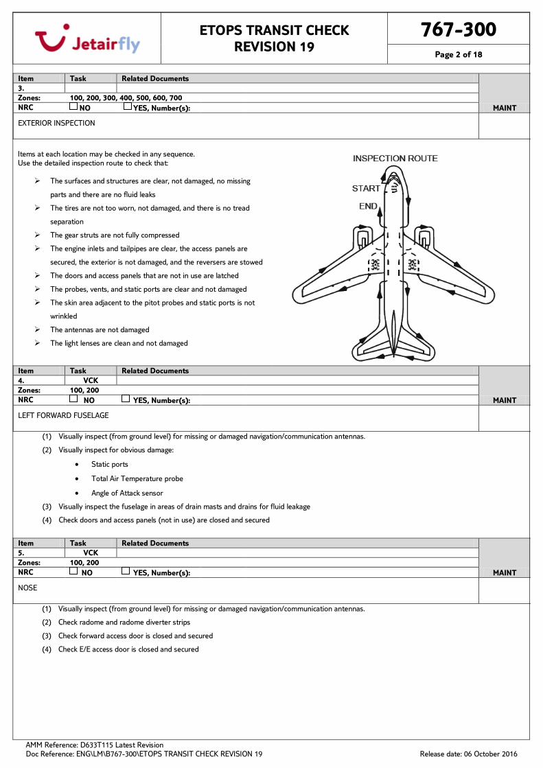
Items at each location may be checked in any sequence. Use the detailed inspection route to check that:
The surfaces and structures are clear, not damaged, no missing
parts and there are no fluid leaks
The tires are not too worn, not damaged, and there is no tread
separation
The gear struts are not fully compressed
The engine inlets and tailpipes are clear, the access panels are
secured, the exterior is not damaged, and the reversers are stowed
The doors and access panels that are not in use are latched
The probes, vents, and static ports are clear and not damaged
The skin area adjacent to the pitot probes and static ports is not
wrinkled
The antennas are not damaged
The light lenses are clean and not damaged
Item Task Related Documents
MAINT
4. VCK Zones: 100, 200 NRC NO YES, Number(s):
LEFT FORWARD FUSELAGE
(1) Visually inspect (from ground level) for missing or damaged navigation/communication antennas.
(2) Visually inspect for obvious damage:
• Static ports
• Total Air Temperature probe
• Angle of Attack sensor
(3) Visually inspect the fuselage in areas of drain masts and drains for fluid leakage
(4) Check doors and access panels (not in use) are closed and secured
Item Task Related Documents
MAINT
5. VCK Zones: 100, 200 NRC NO YES, Number(s):
NOSE
(1) Visually inspect (from ground level) for missing or damaged navigation/communication antennas.
(2) Check radome and radome diverter strips
(3) Check forward access door is closed and secured
(4) Check E/E access door is closed and secured
ETOPS TRANSIT CHECK REVISION 19
767-300
Page 3 of 18
AMM Reference: D633T115 Latest Revision Doc Reference: ENG\LM\B767-300\ETOPS TRANSIT CHECK REVISION 19
Release date: 06 October 2016
Item Task Related Documents
MAINT
6. GVI MP 32-029-00-02 AMM 32-45-04-216-001-003 MP 32-030-00-01 AMM 32-45-03-216-001
Zones: 710 NRC NO YES, Number(s):
NOSE WHEEL WELL
(1) Visually inspect the nose landing gear tires and wheels for obvious damage (Figure 1)
(2) Check Nose Gear strut and doors
(3) Check Nose wheel steering assembly
(4) Check exterior lights
• Taxi lights
• Left and Right Nose Gear Landing Lights
(5) Nose gear steering lockout pin………………………………………………………………………As needed
(6) Gear pin……………………………………………………………………………………………………………..As needed
(7) Nose wheel spin brake (snubbers)………………………………………………………………..In place
(8) Wheel well light switches…………………………………………………………………………………As needed
Item Task Related Documents
MAINT
7. VCK Zones: 100, 200 NRC NO YES, Number(s):
RIGHT FORWARD FUSELAGE
(1) Visually inspect (from ground level) for missing or damaged navigation/communication antennas.
(2) Visually inspect for obvious damage:
• Pitot static probes
• Angle of Attack sensor
• Static ports
(3) Visually inspect the crew oxygen discharge indicator disc for presence
(4) Visually inspect the fuselage in areas of drain masts and drains for fluid leakage
(5) Check doors and access panels (not in use) are closed and secured
(6) Check negative pressure relief doors are closed.
Item Task Related Documents
MAINT
8. VCK Zones: 100, 600 NRC NO YES, Number(s):
RIGHT WING ROOT, PACK AND LOWER FUSELAGE
(1) Check Probes, sensors, ports, vents, for obvious damage and drains for fluid leakage (as applicable)
(2) Check exterior lights
• Lower body anti-collision light
• Wing illumination lights
• Wing landing light
• Runway Turnoff light
(3) Visually inspect the RH pack ram air inlet and exhaust door for no obstructions
(4) Check that the pack access doors are closed and secured
(5) Check the leading edge slats
(6) Check that the fuel tank measuring sticks are flush and secured
ETOPS TRANSIT CHECK REVISION 19
767-300
Page 4 of 18
AMM Reference: D633T115 Latest Revision Doc Reference: ENG\LM\B767-300\ETOPS TRANSIT CHECK REVISION 19
Release date: 06 October 2016
Item Task Related Documents
MAINT
9. GVI Zones: 420 NRC NO YES, Number(s):
RIGHT ENGINE
(1) Visually inspect the engine cowlings for obvious damage, open blow out doors, open latches and sings of fluid leakages.
(2) Visually inspect the inlet cowl, fan rotor spinner, engine inlet probes and the fan rotor blades for obvious damage.
(3) Visually inspect the turbine exhaust sleeve, the exhaust tail plug, exhaust case strut and the visible turbine blades for obvious damage and
evidence of metal/oil accumulation.
(4) Check that the thrust reverser is in the stowed position.
(5) Check that engine and pylon access panels are closed and secured.
Item Task Related Documents
MAINT
10. VCK Zones: 600 NRC NO YES, Number(s):
RIGHT WING AND LEADING EDGE
(1) Visually inspect the lower wing surfaces from ground level for obvious damage and fuel leakage
(2) Check that access panels are closed and secured
(3) Check the leading edge slats
(4) Check the fuel tank vent
(5) Check that the fuel tank measuring sticks are flush and secured
Item Task Related Documents
MAINT
11. GVI MP 27-052-01-01 AMM 27-05-03-202-805 Zones: 600 NRC NO YES, Number(s):
RIGHT WING TIP AND TRAILING EDGE
(1) Visually inspect the wing tip from ground level for obvious damage and fuel leakage
(2) Check visible portion of right wing flight control surfaces, from ground level, for obvious damage.
(3) Check exterior lights:
• Upper body anti-collision light
• Forward and rear position light
• Right wing anti-collision light
(4) Check the static discharge wicks
(5) Check fuel jettison nozzle
Item Task Related Documents
MAINT
12. GVI MP 32-024-00-05 AMM 32-41-08-216-001-003 MP 32-029-00-02 AMM 32-45-04-216-001-003 MP 32-030-00-01 AMM 32-45-03-216-001
Zones: 740 NRC NO YES, Number(s):
RIGHT MAIN GEAR AND WHEEL WELL
(1) Visually inspect the RH main landing gear tires and wheels for obvious damage. (Figure 1)
(2) Verify that wheel chocks are in place as needed.
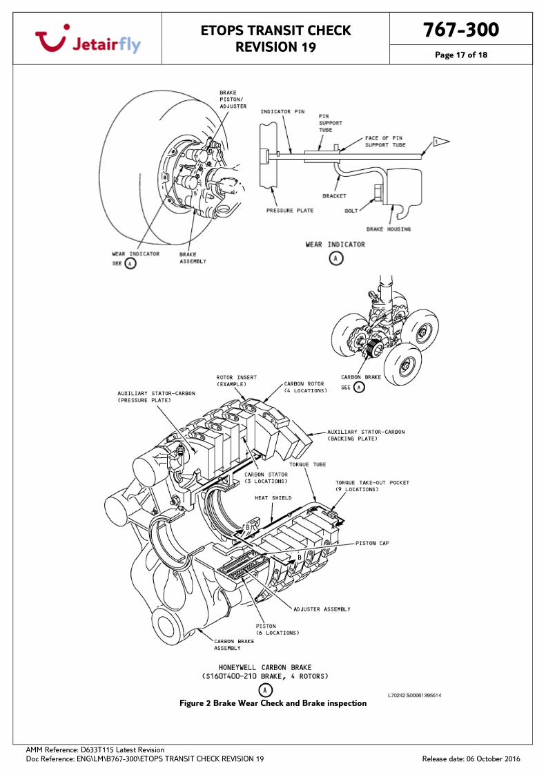
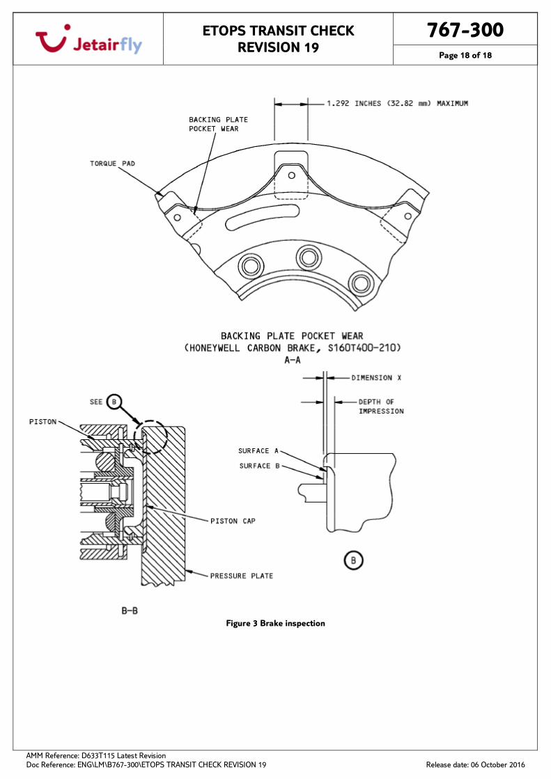
(3) Check each brake wear indicator (Figure 2 and 3)
If the parking brake is set, the brake wear indicator pins must extend out of the guides.
(4) Check gear strut, actuators, and doors.
(5) Check that the LDG Hydraulic lines are secured.
(6) Gear pins………………………………………………………………….as needed
ETOPS TRANSIT CHECK REVISION 19
767-300
Page 5 of 18
AMM Reference: D633T115 Latest Revision Doc Reference: ENG\LM\B767-300\ETOPS TRANSIT CHECK REVISION 19
Release date: 06 October 2016
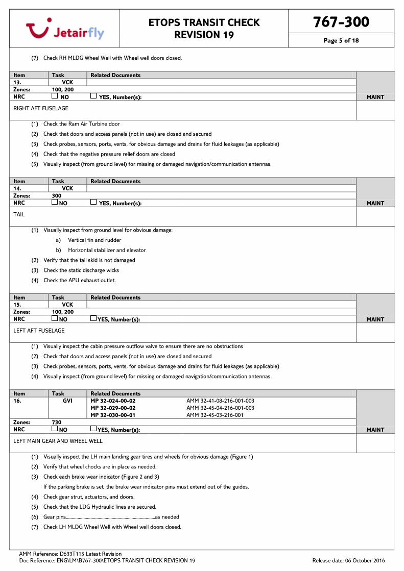
(7) Check RH MLDG Wheel Well with Wheel well doors closed.
Item Task Related Documents
MAINT
13. VCK Zones: 100, 200 NRC NO YES, Number(s):
RIGHT AFT FUSELAGE
(1) Check the Ram Air Turbine door
(2) Check that doors and access panels (not in use) are closed and secured
(3) Check probes, sensors, ports, vents, for obvious damage and drains for fluid leakages (as applicable)
(4) Check that the negative pressure relief doors are closed
(5) Visually inspect (from ground level) for missing or damaged navigation/communication antennas.
Item Task Related Documents
MAINT
14. VCK Zones: 300 NRC NO YES, Number(s):
TAIL
(1) Visually inspect from ground level for obvious damage:
a) Vertical fin and rudder
b) Horizontal stabilizer and elevator
(2) Verify that the tail skid is not damaged
(3) Check the static discharge wicks
(4) Check the APU exhaust outlet.
Item Task Related Documents
MAINT
15. VCK Zones: 100, 200 NRC NO YES, Number(s):
LEFT AFT FUSELAGE
(1) Visually inspect the cabin pressure outflow valve to ensure there are no obstructions
(2) Check that doors and access panels (not in use) are closed and secured
(3) Check probes, sensors, ports, vents, for obvious damage and drains for fluid leakages (as applicable)
(4) Visually inspect (from ground level) for missing or damaged navigation/communication antennas.
Item Task Related Documents
MAINT
16. GVI MP 32-024-00-02 AMM 32-41-08-216-001-003 MP 32-029-00-02 AMM 32-45-04-216-001-003 MP 32-030-00-01 AMM 32-45-03-216-001
Zones: 730 NRC NO YES, Number(s):
LEFT MAIN GEAR AND WHEEL WELL
(1) Visually inspect the LH main landing gear tires and wheels for obvious damage (Figure 1)
(2) Verify that wheel chocks are in place as needed.
(3) Check each brake wear indicator (Figure 2 and 3)
If the parking brake is set, the brake wear indicator pins must extend out of the guides.
(4) Check gear strut, actuators, and doors.
(5) Check that the LDG Hydraulic lines are secured.
(6) Gear pins………………………………………………………………….as needed
(7) Check LH MLDG Wheel Well with Wheel well doors closed.
ETOPS TRANSIT CHECK REVISION 19
767-300
Page 6 of 18
AMM Reference: D633T115 Latest Revision Doc Reference: ENG\LM\B767-300\ETOPS TRANSIT CHECK REVISION 19
Release date: 06 October 2016
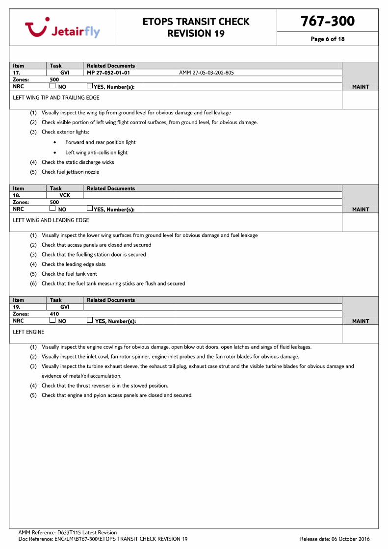
Item Task Related Documents
MAINT
17. GVI MP 27-052-01-01 AMM 27-05-03-202-805 Zones: 500 NRC NO YES, Number(s):
LEFT WING TIP AND TRAILING EDGE
(1) Visually inspect the wing tip from ground level for obvious damage and fuel leakage
(2) Check visible portion of left wing flight control surfaces, from ground level, for obvious damage.
(3) Check exterior lights:
• Forward and rear position light
• Left wing anti-collision light
(4) Check the static discharge wicks
(5) Check fuel jettison nozzle
Item Task Related Documents
MAINT
18. VCK Zones: 500 NRC NO YES, Number(s):
LEFT WING AND LEADING EDGE
(1) Visually inspect the lower wing surfaces from ground level for obvious damage and fuel leakage
(2) Check that access panels are closed and secured
(3) Check that the fuelling station door is secured
(4) Check the leading edge slats
(5) Check the fuel tank vent
(6) Check that the fuel tank measuring sticks are flush and secured
Item Task Related Documents
MAINT
19. GVI Zones: 410 NRC NO YES, Number(s):
LEFT ENGINE
(1) Visually inspect the engine cowlings for obvious damage, open blow out doors, open latches and sings of fluid leakages.
(2) Visually inspect the inlet cowl, fan rotor spinner, engine inlet probes and the fan rotor blades for obvious damage.
(3) Visually inspect the turbine exhaust sleeve, the exhaust tail plug, exhaust case strut and the visible turbine blades for obvious damage and
evidence of metal/oil accumulation.
(4) Check that the thrust reverser is in the stowed position.
(5) Check that engine and pylon access panels are closed and secured.
ETOPS TRANSIT CHECK REVISION 19
767-300
Page 7 of 18
AMM Reference: D633T115 Latest Revision Doc Reference: ENG\LM\B767-300\ETOPS TRANSIT CHECK REVISION 19
Release date: 06 October 2016
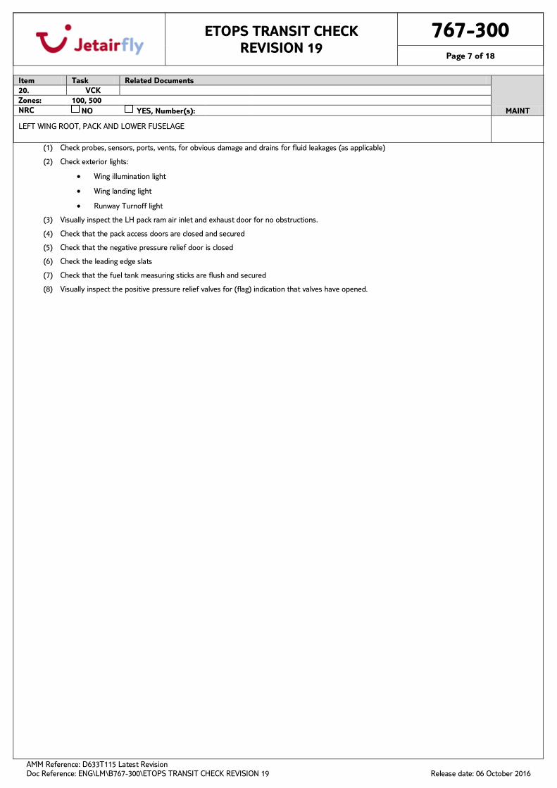
Item Task Related Documents
MAINT
20. VCK Zones: 100, 500 NRC NO YES, Number(s):
LEFT WING ROOT, PACK AND LOWER FUSELAGE
(1) Check probes, sensors, ports, vents, for obvious damage and drains for fluid leakages (as applicable)
(2) Check exterior lights:
• Wing illumination light
• Wing landing light
• Runway Turnoff light
(3) Visually inspect the LH pack ram air inlet and exhaust door for no obstructions.
(4) Check that the pack access doors are closed and secured
(5) Check that the negative pressure relief door is closed
(6) Check the leading edge slats
(7) Check that the fuel tank measuring sticks are flush and secured
(8) Visually inspect the positive pressure relief valves for (flag) indication that valves have opened.
ETOPS TRANSIT CHECK REVISION 19
767-300
Page 8 of 18
AMM Reference: D633T115 Latest Revision Doc Reference: ENG\LM\B767-300\ETOPS TRANSIT CHECK REVISION 19
Release date: 06 October 2016
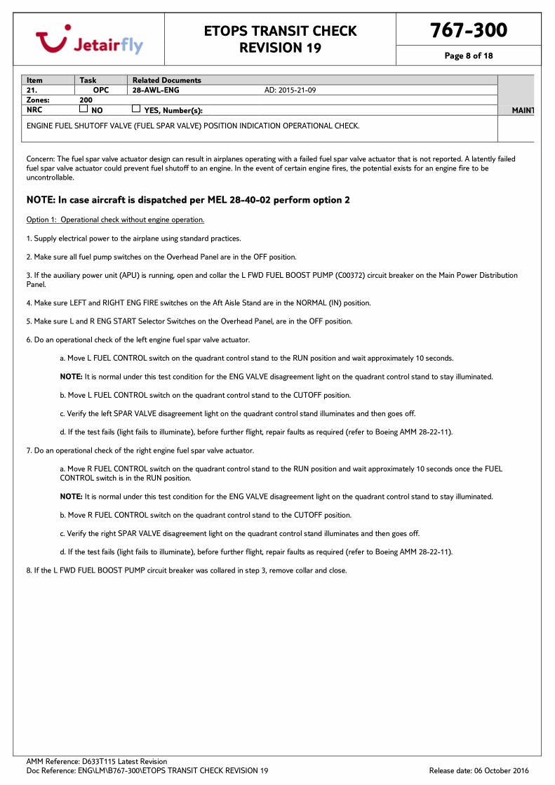
Concern: The fuel spar valve actuator design can result in airplanes operating with a failed fuel spar valve actuator that is not reported. A latently failed fuel spar valve actuator could prevent fuel shutoff to an engine. In the event of certain engine fires, the potential exists for an engine fire to be uncontrollable.
Item Task Related Documents
MAINT
21. OPC 28-AWL-ENG AD: 2015-21-09 Zones: 200 NRC NO YES, Number(s):
ENGINE FUEL SHUTOFF VALVE (FUEL SPAR VALVE) POSITION INDICATION OPERATIONAL CHECK.
NOTE: In case aircraft is dispatched per MEL 28-40-02 perform option 2 Option 1: Operational check without engine operation. 1. Supply electrical power to the airplane using standard practices. 2. Make sure all fuel pump switches on the Overhead Panel are in the OFF position. 3. If the auxiliary power unit (APU) is running, open and collar the L FWD FUEL BOOST PUMP (C00372) circuit breaker on the Main Power Distribution Panel. 4. Make sure LEFT and RIGHT ENG FIRE switches on the Aft Aisle Stand are in the NORMAL (IN) position. 5. Make sure L and R ENG START Selector Switches on the Overhead Panel, are in the OFF position. 6. Do an operational check of the left engine fuel spar valve actuator.
a. Move L FUEL CONTROL switch on the quadrant control stand to the RUN position and wait approximately 10 seconds. NOTE: It is normal under this test condition for the ENG VALVE disagreement light on the quadrant control stand to stay illuminated. b. Move L FUEL CONTROL switch on the quadrant control stand to the CUTOFF position. c. Verify the left SPAR VALVE disagreement light on the quadrant control stand illuminates and then goes off. d. If the test fails (light fails to illuminate), before further flight, repair faults as required (refer to Boeing AMM 28-22-11).
7. Do an operational check of the right engine fuel spar valve actuator.
a. Move R FUEL CONTROL switch on the quadrant control stand to the RUN position and wait approximately 10 seconds once the FUEL CONTROL switch is in the RUN position. NOTE: It is normal under this test condition for the ENG VALVE disagreement light on the quadrant control stand to stay illuminated. b. Move R FUEL CONTROL switch on the quadrant control stand to the CUTOFF position. c. Verify the right SPAR VALVE disagreement light on the quadrant control stand illuminates and then goes off. d. If the test fails (light fails to illuminate), before further flight, repair faults as required (refer to Boeing AMM 28-22-11).
8. If the L FWD FUEL BOOST PUMP circuit breaker was collared in step 3, remove collar and close.
ETOPS TRANSIT CHECK REVISION 19
767-300
Page 9 of 18
AMM Reference: D633T115 Latest Revision Doc Reference: ENG\LM\B767-300\ETOPS TRANSIT CHECK REVISION 19
Release date: 06 October 2016
Option2: Perform an inspection of the fuel spar valve actuator position. NOTE: This inspection may be most useful whenever the SPAR VALVE light does not function properly. 1. Make sure the L FUEL CONTROL switch on the quadrant control stand is in the CUTOFF position. NOTE: It is not necessary to cycle the FUEL CONTROL switch to do this inspection. 2. Inspect the left engine fuel spar valve actuator located in the left rear spar. NOTE: The Fuel Spar Valve actuators are located behind main gear doors on the rear spar.
a. Verify the manual override handle on the engine fuel spar valve actuator is in the CLOSED position. b. Repair or replace any fuel spar valve actuator that is not in the CLOSED position (refer to Boeing AMM 28-22-11).
3. Make sure the R FUEL CONTROL switch on the quadrant control stand is in the CUTOFF position. NOTE: It is not necessary to cycle the FUEL CONTROL switch to do this inspection. 4. Inspect the right engine fuel spar valve actuator located in the right rear spar. NOTE: The Fuel Spar Valve actuators are located behind main gear doors on the rear spar.
a. Verify the manual override handle on the engine fuel spar valve actuator is in the CLOSED position. b. Repair or replace any fuel spar valve actuator that is not in the CLOSED position (refer to Boeing AMM 28-22-11).
ETOPS TRANSIT CHECK REVISION 19
767-300
Page 10 of 18
AMM Reference: D633T115 Latest Revision Doc Reference: ENG\LM\B767-300\ETOPS TRANSIT CHECK REVISION 19
Release date: 06 October 2016
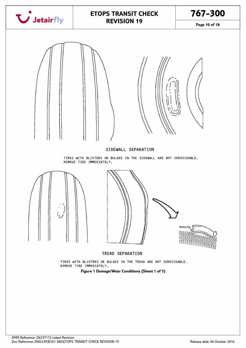
Figure 1 Damage/Wear Conditions (Sheet 1 of 7)
ETOPS TRANSIT CHECK REVISION 19
767-300
Page 11 of 18
AMM Reference: D633T115 Latest Revision Doc Reference: ENG\LM\B767-300\ETOPS TRANSIT CHECK REVISION 19
Release date: 06 October 2016
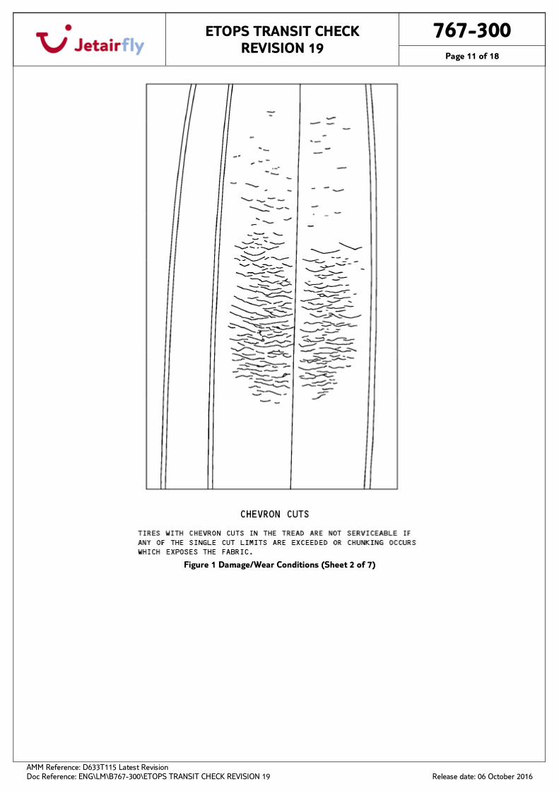
Figure 1 Damage/Wear Conditions (Sheet 2 of 7)
ETOPS TRANSIT CHECK REVISION 19
767-300
Page 12 of 18
AMM Reference: D633T115 Latest Revision Doc Reference: ENG\LM\B767-300\ETOPS TRANSIT CHECK REVISION 19
Release date: 06 October 2016
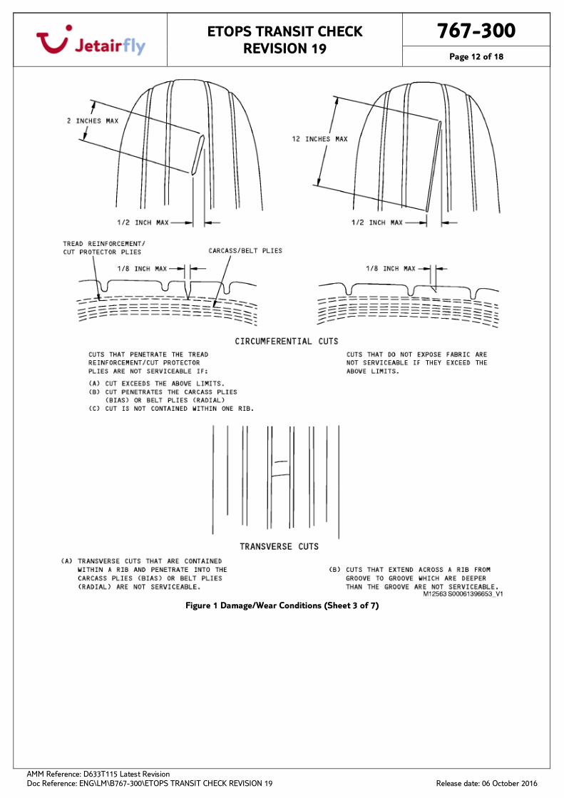
Figure 1 Damage/Wear Conditions (Sheet 3 of 7)
ETOPS TRANSIT CHECK REVISION 19
767-300
Page 13 of 18
AMM Reference: D633T115 Latest Revision Doc Reference: ENG\LM\B767-300\ETOPS TRANSIT CHECK REVISION 19
Release date: 06 October 2016
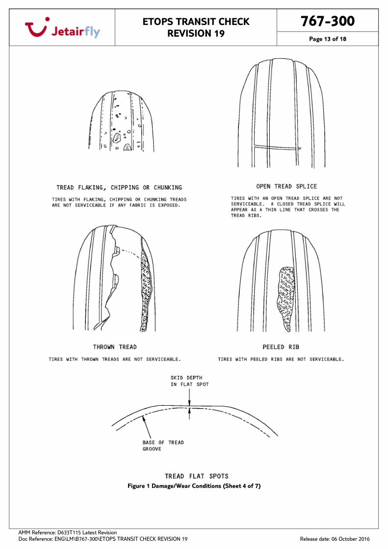
Figure 1 Damage/Wear Conditions (Sheet 4 of 7)
ETOPS TRANSIT CHECK REVISION 19
767-300
Page 14 of 18
AMM Reference: D633T115 Latest Revision Doc Reference: ENG\LM\B767-300\ETOPS TRANSIT CHECK REVISION 19
Release date: 06 October 2016
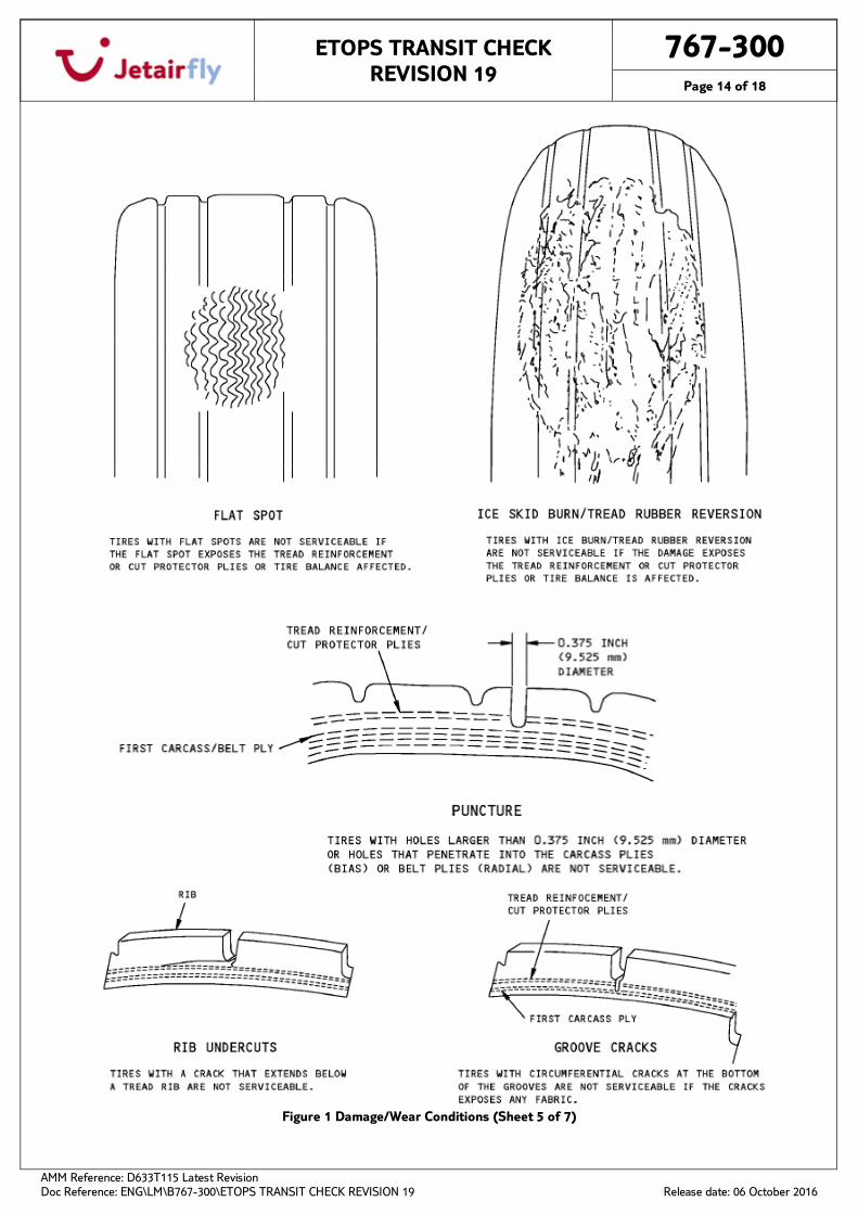
Figure 1 Damage/Wear Conditions (Sheet 5 of 7)
ETOPS TRANSIT CHECK REVISION 19
767-300
Page 15 of 18
AMM Reference: D633T115 Latest Revision Doc Reference: ENG\LM\B767-300\ETOPS TRANSIT CHECK REVISION 19
Release date: 06 October 2016
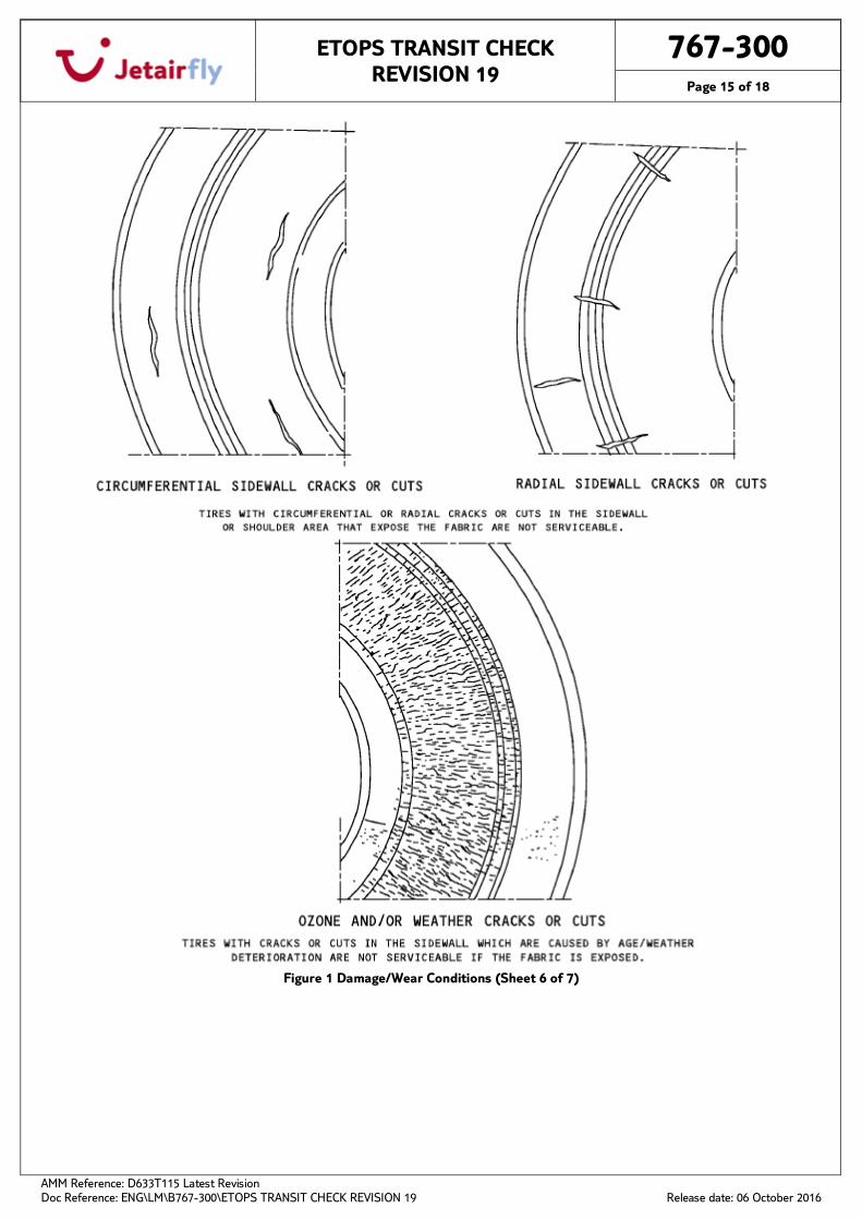
Figure 1 Damage/Wear Conditions (Sheet 6 of 7)
ETOPS TRANSIT CHECK REVISION 19
767-300
Page 16 of 18
AMM Reference: D633T115 Latest Revision Doc Reference: ENG\LM\B767-300\ETOPS TRANSIT CHECK REVISION 19
Release date: 06 October 2016
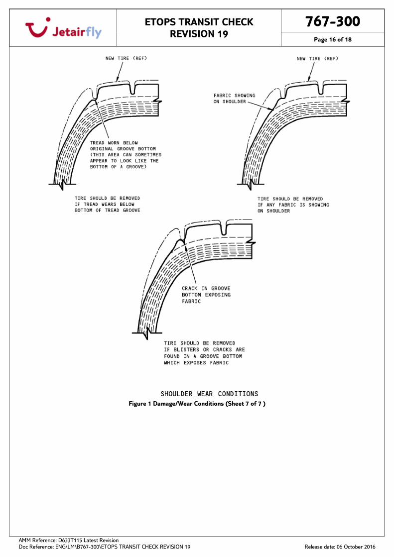
Figure 1 Damage/Wear Conditions (Sheet 7 of 7 )
ETOPS TRANSIT CHECK REVISION 19
767-300
Page 17 of 18
AMM Reference: D633T115 Latest Revision Doc Reference: ENG\LM\B767-300\ETOPS TRANSIT CHECK REVISION 19
Release date: 06 October 2016
Figure 2 Brake Wear Check and Brake inspection
ETOPS TRANSIT CHECK REVISION 19
767-300
Page 18 of 18
AMM Reference: D633T115 Latest Revision Doc Reference: ENG\LM\B767-300\ETOPS TRANSIT CHECK REVISION 19
Release date: 06 October 2016
Figure 3 Brake inspection