getting to grips with etops - onur...
TRANSCRIPT

Getting to Grips with ETOPS: The Flight Operations View
1
Flig
ht O
pera
tions
Sup
port
& L
ine
Ass
ista
nce
Getting to grips with ETOPS
Volume II: THE FLIGHT OPERATIONS VIEW
Getting to Grips with ETOPS: The Flight Operations View
2
Left Intentionally Blank
Getting to grips with ETOPS: Table Of Content The Flight Operations View
3
Table of Content Table of contents
Table of Content ........................................................................................................................... 3
1 INTRODUCTION .................................................................................................................. 5
1.1 WHAT DOES ETOPS MEAN? ............................................................................................... 5
1.2 THE ADVANTAGES OF ETOPS ........................................................................................... 6
2 AREA OF OPERATIONS ..................................................................................................... 7
2.1 IS ETOPS NECESSARY? ..................................................................................................... 7 2.1.1 INTRODUCTION .................................................................................................... 7 2.1.2 WHAT IS AN ADEQUATE AIRPORT? ................................................................... 8 2.1.3 WHAT IS THE APPROVED OEI DIVERSION SPEED? ........................................ 9 2.1.4 WHAT ARE THE REFERENCE GROSS WEIGHT AND DIVERSION FL? ......... 11
2.2 WHAT IS THE REQUIRED MAXIMUM DIVERSION TIME? ............................................... 14 2.2.1 EEP/EXP AND ETOPS SECTOR ........................................................................ 14 2.2.2 COVERING THE ETOPS SECTOR ..................................................................... 15 2.2.3 SUMMARY ........................................................................................................... 17
3 FLIGHT DISPATCH ............................................................................................................ 18
3.1 ETOPS ALTERNATE AIRPORTS ....................................................................................... 18 3.1.1 ETP AND TIME WINDOW .................................................................................... 18 3.1.2 DISPATCH WEATHER MINIMA .......................................................................... 23 3.1.3 SURFACE CONDITIONS ..................................................................................... 25 3.1.4 ETOPS ALTERNATE AIRPORT SELECTION FORM ......................................... 28
3.2 OBSTACLE CLEARANCE ................................................................................................... 29
3.3 FUEL CONSIDERATIONS ................................................................................................... 29 3.3.1 REQUIREMENTS AND SCENARII ...................................................................... 30 3.3.2 FUEL RESERVES ................................................................................................ 33
3.4 TIME-LIMITED SYSTEMS ................................................................................................... 35
3.5 PLOTTING CHART .............................................................................................................. 36
3.6 DISPATCH CHECKLIST EXAMPLE .................................................................................... 37
3.7 ETOPS BEYOND 180 MINUTES SPECIFICITIES .............................................................. 38
Getting to grips with ETOPS: Table Of Content The Flight Operations View
4
4 THE ETOPS FLIGHT .......................................................................................................... 39
4.1 THE FLIGHT PREPARATION ............................................................................................. 39
4.2 ETOPS ELEMENTS OF THE CFP ...................................................................................... 40
4.3 COCKPIT PREPARATION .................................................................................................. 42 4.3.1 PREFLIGHT CHECKS .......................................................................................... 42 4.3.2 DATA LOADING ................................................................................................... 43
4.4 BEFORE REACHING THE EEP .......................................................................................... 45
4.5 FLYING THE ETOPS SECTOR ........................................................................................... 45
4.6 DIVERSION.......................................................................................................................... 46
Getting to grips with ETOPS: Introduction The Flight Operations View
5
1 INTRODUCTION
1.1 WHAT DOES ETOPS MEAN? Due to the poor reliability of piston engines in the early 1950s, the ICAO recommended that no aircraft be operated beyond 90 min with all engines operative, from a diversion airport, except if the route could be flown with two engines inoperative. The FAA was even more restrictive, because they limited the use of tris, for a short while, and twins, to areas where they were less than 60 min away, at any time, from an en-route diversion airport. With the change from piston engines to much more reliable jet engines, it became clear that this limitation would have to be revised. This resulted in the creation of a new regulation: ETOPS. At the beginning, ETOPS stood for Extended Twins OPerationS. It was made of sets of certification and operational requirements. These requirements were to be fulfilled in order to operate beyond the above-mentioned thresholds. The requirements are fully described in Volume 1 of this publication. Since its creation, ETOPS has evolved, mainly to enable operations of twins beyond 180 min diversion time:
• Today, the ETOPS acronym has different meanings: o For the EASA, it still stands for Extended Twins OPerationS o For the FAA, however, it now stands for ExTended OPerationS, in order to take
into account the application of this US regulation to passenger-carrying aircraft with more than two engines (i.e. that exclude freighters with more than two engines).
• The ICAO has changed the name of its revised ETOPS regulation to EDTO, that stands for Extended Diversion Time Operations. EDTO is, as the FAA ETOPS, applicable to twins, and to aircraft with more than two engines (Including freighters with more than two engines).
• The EASA has been working on a new regulation, LROPS, or Long Range OPerationS, that is the adaptation of ETOPS requirements to aircraft with more than two engines. The decision to publish this LROPS rule depends on the conclusion of the EASA review of the new ICAO EDTO rule.
In this brochure, we will use the generic term “ETOPS” and pinpoint the differences of the various regulations when necessary.
Getting to grips with ETOPS: Introduction The Flight Operations View
6
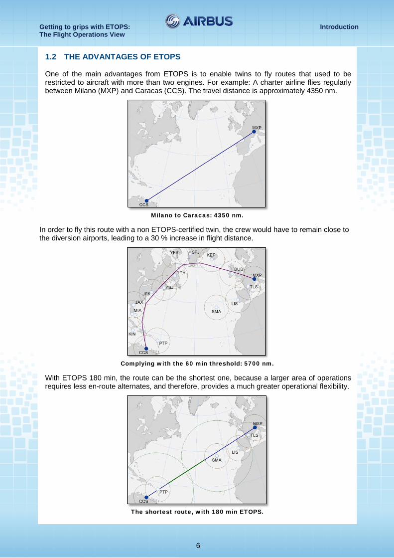
1.2 THE ADVANTAGES OF ETOPS One of the main advantages from ETOPS is to enable twins to fly routes that used to be restricted to aircraft with more than two engines. For example: A charter airline flies regularly between Milano (MXP) and Caracas (CCS). The travel distance is approximately 4350 nm.
Milano to Caracas: 4350 nm.
In order to fly this route with a non ETOPS-certified twin, the crew would have to remain close to the diversion airports, leading to a 30 % increase in flight distance.
Complying with the 60 min threshold: 5700 nm.
With ETOPS 180 min, the route can be the shortest one, because a larger area of operations requires less en-route alternates, and therefore, provides a much greater operational flexibility.
The shortest route, with 180 min ETOPS.
Getting to grips with ETOPS: Area of Operations The Flight Operations View
7
2 AREA OF OPERATIONS
2.1 IS ETOPS NECESSARY? 2.1.1 Introduction An Operator wants to open a new route, or to change the type of aircraft used to fly an existing route. Does this Operator need to apply for an ETOPS operational approval?
ETOPS regulations apply when commercial air-operations are conducted on a route that contains a segment where the aircraft flies beyond a defined flight-time distance from all adequate airports. For a twin-engine aircraft, this threshold is set to 60 min flight-time, in still air and ISA conditions, at an approved one-engine-inoperative (OEI) speed schedule. For tri- and quad-engine aircraft, this threshold has to be set by the National Authority. ICAO regulations recommend that this threshold be set to a 180 min flight-time, in still air and ISA conditions, at an approved all-engine-operative speed. Note: Operators can take advantage of an ISA deviation (Increased True Air Speed (TAS)) is possible if the deviation is
constant during the entire year for the considered route.
Is ETOPS necessary? The answer may be obvious for some routes, for example, the routes that cross the Atlantic Ocean. But perhaps a little less obvious if the route is flown over areas where only few adequate airports are available. To correctly determine if ETOPS is necessary for a specific route, the Operator should apply the following steps:
1. Determination of the intended route to be flown 2. Determination of the possible diversion airports, also called adequate airport(s) (Refer to
section 2.1.2 of this volume) 3. Determination of the maximum diversion distance with a diversion time of 60 min, also called
the ETOPS Threshold Distance (Refer to section 2.1.4 of this volume) 4. Drawing of circles, with a radius equal to the ETOPS Threshold Distance, centered on each
adequate airport 5. If the route goes outside these circles, ETOPS operations are required on the section(s) of
route that are outside these 60 min circles.
This chapter and the following use an example to illustrate the steps that Operators should apply, in order to determine the need for ETOPS, on a specific route. The example is a case study of an Operator that wants to open a new route from Madrid (Spain), to Buenos Aires (Argentina), with an A330 aircraft.
Getting to grips with ETOPS: Area of Operations The Flight Operations View
8
2.1.2 What is an adequate airport? An adequate airport is an airport that the aircraft can safely divert to, in the case of an emergency, i.e.:
• It satisfies the aircraft performance requirements applicable at the expected landing weight
• It is available at the expected time of use • Overflying and landing authorizations are granted • It has ground operational services like:
o ATC o Meteorological and air information offices o Lighting capabilities
• It has, at least, one let-down navaid available to conduct an instrument approach, like: o An ILS o A VOR o An NDB, etc.
• The Rescue and Fire Fighting category of the airport is at least a level 4 (ICAO SARP Annex 14 (Paragraph 9.2, Table 9-1)). If the diversion time is beyond 180 minutes, the FAA requests that the Rescue and Fire Fighting category be at least a level 7.
The FAA requests also a passenger recovery plan for each adequate airport, if the maximum diversion time is beyond 180 minutes, or if the flight is conducted in a polar region. This passenger recovery plan must address the safety and comfort of stranded passengers and crewmembers at the diversion airport. The passenger recovery plan must also address the prompt retrieval of passengers and crewmembers from the airport.
In order to select the adequate airports, the Operator may also consider the following criteria:
• The consistency of the Pavement Classification Number (PCN) of the runway(s) with the Aircraft Classification Number (ACN), even if, in the case of an emergency, it is not necessary to satisfy a runway pavement requirement normally considered for the regular use of an airport (“ICAO Convention - Annex 14” and “ICAO Airport Manual, Document 9157 - AN/91”).
• The existence of health-care facilities • The existence of maintenance facilities • The existence of airport services to handle the aircraft and provide catering (fuel, food,
etc.) • The existence of airport facilities to receive and accommodate the passengers • Any other specific requirements applicable to the Operator.
The above-mentioned requirements do not take into account the actual weather at the airport: The study is based on theoretical weather conditions only. The actual weather will be taken into considerations later on, for the dispatch of the flight.
Finally, the local operational authorities must validate the list of adequate airports that the Operator has selected.
The following chart illustrates the adequate airports for the route from Madrid to Buenos Aires:

Getting to grips with ETOPS: Area of Operations The Flight Operations View
9
MAD-EZE: Adequate Airports
2.1.3 What is the approved OEI diversion speed? It is a Mach/IAS speed schedule an Operator is expected to use in the case of a diversion after an engine failure. This speed is approved by the Operator’s National Authority.
In practice, this OEI diversion speed ranges from Green Dot speed (Best lift-over-drag-ratio speed) to VMO/MMO (Maximum certified operating speed). The aircraft is designed, tested and certified to safely fly within this range of speeds, even with one engine inoperative, and with the remaining engine thrust set to Maximum Continuous Thrust (MCT).
Each individual Operator selects its OEI diversion speed in accordance with their route structure and associated constraints. Note: In flight, and as permitted by the operational regulations, the pilot in command can decide to deviate from the OEI
diversion speed, after the flight crew assesses the current situation.
A diversion at high speed maximizes the diversion distance. A diversion at low speed reduces it. But, at the same time, a diversion at low speed allows a higher level-off and minimizes the fuel consumption.
What diversion strategy should the Operator select? For non-ETOPS operations, in the case of an engine failure, the Operator can select either the standard or the obstacle clearance strategies:
• The standard strategy corresponds to a descent at cruise Mach/300 kt IAS down to an altitude near the LRC ceiling, and a diversion cruise at LRC speed
• The obstacle clearance strategy corresponds to a drift-down at Green Dot speed until the obstacles are cleared, and the application of the standard strategy thereafter.
The operational documentation (e.g. the Flight Crew Operating Manual (FCOM)) describes both diversion strategies, in detail. For ETOPS operations, in the case of an engine failure, there is no objection to use either the standard strategy, or the obstacle clearance strategy. However, the associated diversion speeds, respectively LRC speed and Green Dot speed, are substantially low speeds, that limit the maximum diversion distance.
Getting to grips with ETOPS: Area of Operations The Flight Operations View
10
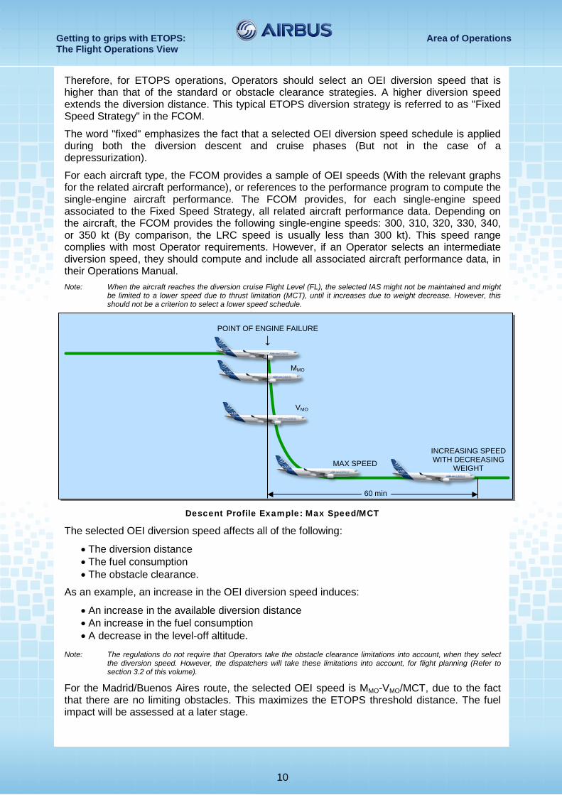
Therefore, for ETOPS operations, Operators should select an OEI diversion speed that is higher than that of the standard or obstacle clearance strategies. A higher diversion speed extends the diversion distance. This typical ETOPS diversion strategy is referred to as "Fixed Speed Strategy" in the FCOM.
The word "fixed" emphasizes the fact that a selected OEI diversion speed schedule is applied during both the diversion descent and cruise phases (But not in the case of a depressurization).
For each aircraft type, the FCOM provides a sample of OEI speeds (With the relevant graphs for the related aircraft performance), or references to the performance program to compute the single-engine aircraft performance. The FCOM provides, for each single-engine speed associated to the Fixed Speed Strategy, all related aircraft performance data. Depending on the aircraft, the FCOM provides the following single-engine speeds: 300, 310, 320, 330, 340, or 350 kt (By comparison, the LRC speed is usually less than 300 kt). This speed range complies with most Operator requirements. However, if an Operator selects an intermediate diversion speed, they should compute and include all associated aircraft performance data, in their Operations Manual. Note: When the aircraft reaches the diversion cruise Flight Level (FL), the selected IAS might not be maintained and might
be limited to a lower speed due to thrust limitation (MCT), until it increases due to weight decrease. However, this should not be a criterion to select a lower speed schedule.
Descent Profile Example: Max Speed/MCT
The selected OEI diversion speed affects all of the following:
• The diversion distance • The fuel consumption • The obstacle clearance.
As an example, an increase in the OEI diversion speed induces:
• An increase in the available diversion distance • An increase in the fuel consumption • A decrease in the level-off altitude.
Note: The regulations do not require that Operators take the obstacle clearance limitations into account, when they select
the diversion speed. However, the dispatchers will take these limitations into account, for flight planning (Refer to section 3.2 of this volume).
For the Madrid/Buenos Aires route, the selected OEI speed is MMO-VMO/MCT, due to the fact that there are no limiting obstacles. This maximizes the ETOPS threshold distance. The fuel impact will be assessed at a later stage.
60 min
POINT OF ENGINE FAILURE ↓
MMO
VMO
MAX SPEED INCREASING SPEED WITH DECREASING
WEIGHT
Getting to grips with ETOPS: Area of Operations The Flight Operations View
11
2.1.4 What are the reference gross weight and diversion FL? Regulations do not define the aircraft Reference Gross Weight (RGW) to be considered. The RGW may range from the Takeoff Weight (TOW) to the Landing Weight (LW), depending on the authorities. A conservative method is to initialize the RGW with the aircraft weight after one hour flight (i.e. TOW minus the weight corresponding to one hour of fuel used), for the calculation of the ETOPS threshold.
The diversion FL is the optimum diversion FL associated with the RGW. This optimum diversion FL provides the maximum diversion distance.
The calculation of the RGW and the diversion FL may require some iteration.
The FCOM provides the “ETOPS MAXIMUM DIVERSION DISTANCE” and the diversion FL. Operators can also compute the diversion FL and the ETOPS maximum diversion distance with a performance software (e.g. PEP).
In the Madrid/Buenos Aires example, the A330 weights 210 000 kg one hour after takeoff from MAD.
By entering the following FCOM table with these values:
• SPEED SCHEDULE: MMO-VMO/MCT • AIRCRAFT WEIGHT AT CRITICAL POINT (KG): 210 000 • DIVERSION TIME (MIN): 60
Getting to grips with ETOPS: Area of Operations The Flight Operations View
12
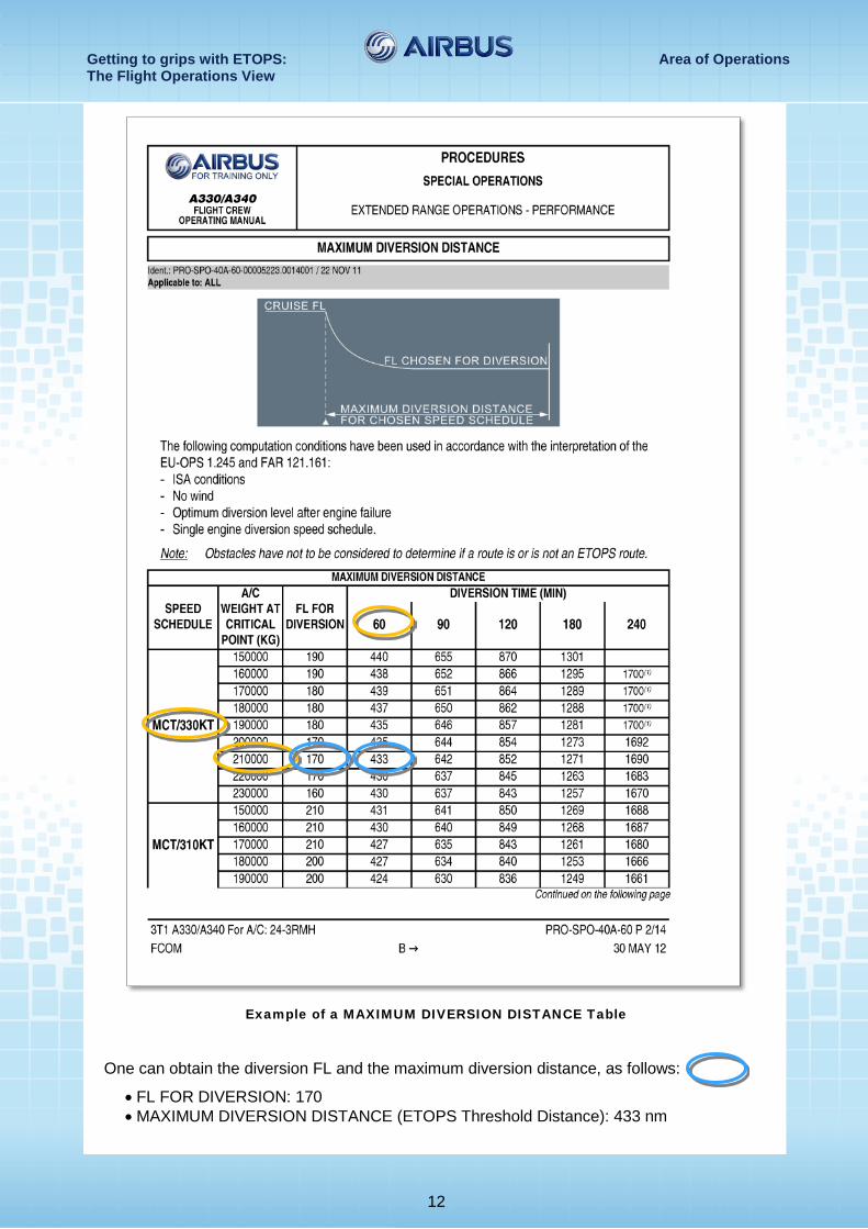
Example of a MAXIMUM DIVERSION DISTANCE Table
One can obtain the diversion FL and the maximum diversion distance, as follows:
• FL FOR DIVERSION: 170 • MAXIMUM DIVERSION DISTANCE (ETOPS Threshold Distance): 433 nm
Getting to grips with ETOPS: Area of Operations The Flight Operations View
13
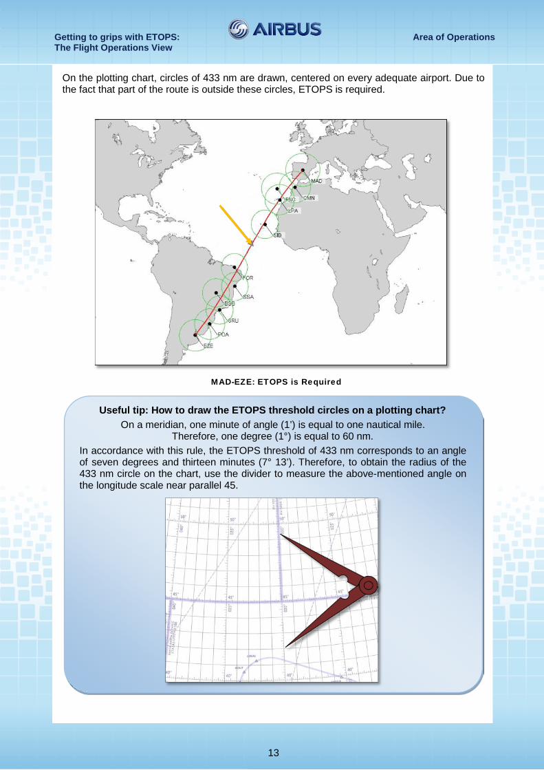
On the plotting chart, circles of 433 nm are drawn, centered on every adequate airport. Due to the fact that part of the route is outside these circles, ETOPS is required.
MAD-EZE: ETOPS is Required
Useful tip: How to draw the ETOPS threshold circles on a plotting chart?
On a meridian, one minute of angle (1’) is equal to one nautical mile. Therefore, one degree (1°) is equal to 60 nm.
In accordance with this rule, the ETOPS threshold of 433 nm corresponds to an angle of seven degrees and thirteen minutes (7° 13’). Therefore, to obtain the radius of the 433 nm circle on the chart, use the divider to measure the above-mentioned angle on the longitude scale near parallel 45.
Getting to grips with ETOPS: Area of Operations The Flight Operations View
14
2.2 WHAT IS THE REQUIRED MAXIMUM DIVERSION TIME? This chapter describes the method that Operators should apply to determine the required maximum diversion time, on an ETOPS route.
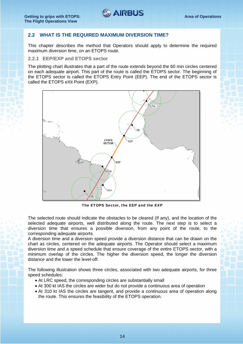
2.2.1 EEP/EXP and ETOPS sector The plotting chart illustrates that a part of the route extends beyond the 60 min circles centered on each adequate airport. This part of the route is called the ETOPS sector. The beginning of the ETOPS sector is called the ETOPS Entry Point (EEP). The end of the ETOPS sector is called the ETOPS eXit Point (EXP).
The ETOPS Sector, the EEP and the EXP
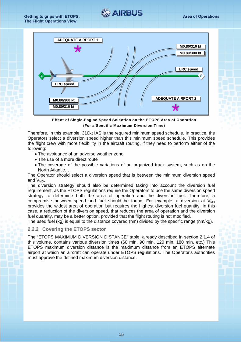
The selected route should indicate the obstacles to be cleared (If any), and the location of the selected adequate airports, well distributed along the route. The next step is to select a diversion time that ensures a possible diversion, from any point of the route, to the corresponding adequate airports. A diversion time and a diversion speed provide a diversion distance that can be drawn on the chart as circles, centered on the adequate airports. The Operator should select a maximum diversion time and a speed schedule that ensure coverage of the entire ETOPS sector, with a minimum overlap of the circles. The higher the diversion speed, the longer the diversion distance and the lower the level-off. The following illustration shows three circles, associated with two adequate airports, for three speed schedules:
• At LRC speed, the corresponding circles are substantially small • At 300 kt IAS the circles are wider but do not provide a continuous area of operation • At 310 kt IAS the circles are tangent, and provide a continuous area of operation along
the route. This ensures the feasibility of the ETOPS operation.
Getting to grips with ETOPS: Area of Operations The Flight Operations View
15
Effect of Single-Engine Speed Selection on the ETOPS Area of Operation
(For a Specific Maximum Diversion Time)
Therefore, in this example, 310kt IAS is the required minimum speed schedule. In practice, the Operators select a diversion speed higher than this minimum speed schedule. This provides the flight crew with more flexibility in the aircraft routing, if they need to perform either of the following:
• The avoidance of an adverse weather zone • The use of a more direct route • The coverage of the possible variations of an organized track system, such as on the
North Atlantic… The Operator should select a diversion speed that is between the minimum diversion speed and VMO. The diversion strategy should also be determined taking into account the diversion fuel requirement, as the ETOPS regulations require the Operators to use the same diversion speed strategy to determine both the area of operation and the diversion fuel. Therefore, a compromise between speed and fuel should be found: For example, a diversion at VMO provides the widest area of operation but requires the highest diversion fuel quantity. In this case, a reduction of the diversion speed, that reduces the area of operation and the diversion fuel quantity, may be a better option, provided that the flight routing is not modified. The used fuel (kg) is equal to the distance covered (nm) divided by the specific range (nm/kg).
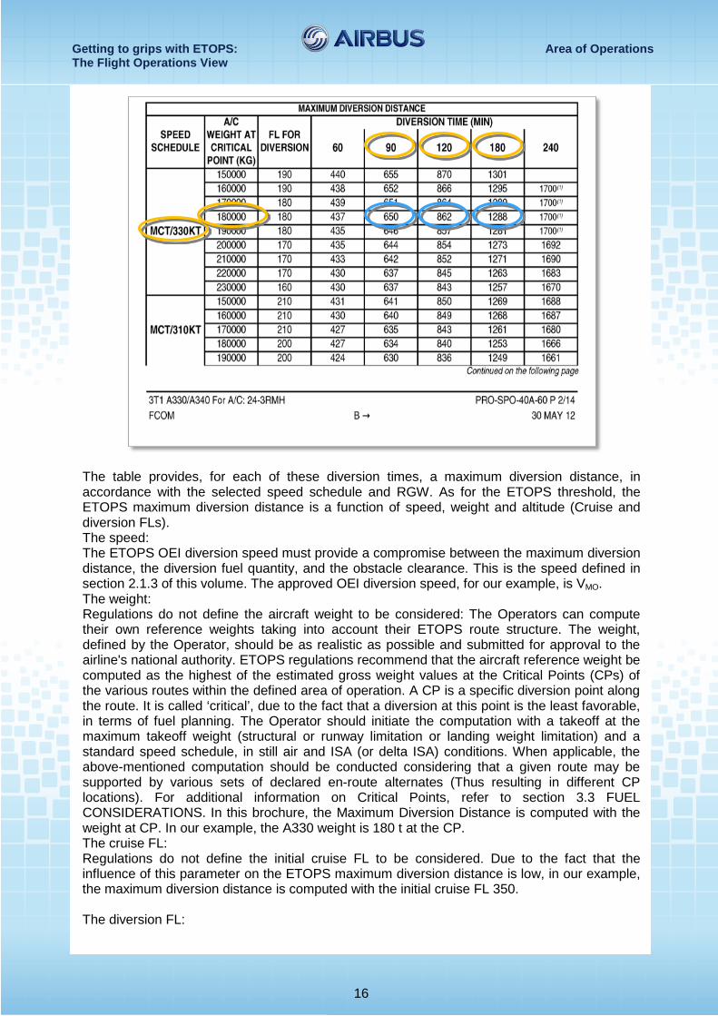
2.2.2 Covering the ETOPS sector The “ETOPS MAXIMUM DIVERSION DISTANCE” table, already described in section 2.1.4 of this volume, contains various diversion times (60 min, 90 min, 120 min, 180 min, etc.) This ETOPS maximum diversion distance is the maximum distance from an ETOPS alternate airport at which an aircraft can operate under ETOPS regulations. The Operator's authorities must approve the defined maximum diversion distance.
*
*
ADEQUATE AIRPORT 1
ADEQUATE AIRPORT 2
LRC speed
M0.80/300 kt
M0.80/310 kt
M0.80/300 kt
M0.80/310 kt
LRC speed
Getting to grips with ETOPS: Area of Operations The Flight Operations View
16
The table provides, for each of these diversion times, a maximum diversion distance, in accordance with the selected speed schedule and RGW. As for the ETOPS threshold, the ETOPS maximum diversion distance is a function of speed, weight and altitude (Cruise and diversion FLs). The speed: The ETOPS OEI diversion speed must provide a compromise between the maximum diversion distance, the diversion fuel quantity, and the obstacle clearance. This is the speed defined in section 2.1.3 of this volume. The approved OEI diversion speed, for our example, is VMO. The weight: Regulations do not define the aircraft weight to be considered: The Operators can compute their own reference weights taking into account their ETOPS route structure. The weight, defined by the Operator, should be as realistic as possible and submitted for approval to the airline's national authority. ETOPS regulations recommend that the aircraft reference weight be computed as the highest of the estimated gross weight values at the Critical Points (CPs) of the various routes within the defined area of operation. A CP is a specific diversion point along the route. It is called ‘critical’, due to the fact that a diversion at this point is the least favorable, in terms of fuel planning. The Operator should initiate the computation with a takeoff at the maximum takeoff weight (structural or runway limitation or landing weight limitation) and a standard speed schedule, in still air and ISA (or delta ISA) conditions. When applicable, the above-mentioned computation should be conducted considering that a given route may be supported by various sets of declared en-route alternates (Thus resulting in different CP locations). For additional information on Critical Points, refer to section 3.3 FUEL CONSIDERATIONS. In this brochure, the Maximum Diversion Distance is computed with the weight at CP. In our example, the A330 weight is 180 t at the CP. The cruise FL: Regulations do not define the initial cruise FL to be considered. Due to the fact that the influence of this parameter on the ETOPS maximum diversion distance is low, in our example, the maximum diversion distance is computed with the initial cruise FL 350. The diversion FL:
Getting to grips with ETOPS: Area of Operations The Flight Operations View
17
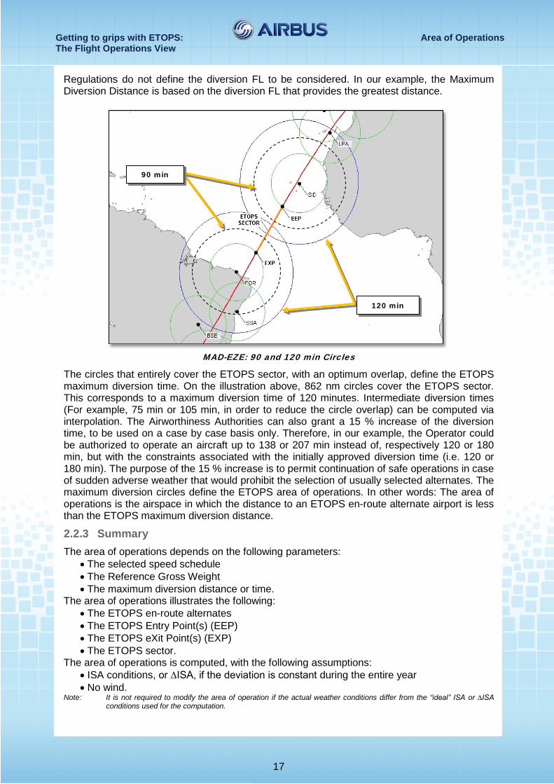
Regulations do not define the diversion FL to be considered. In our example, the Maximum Diversion Distance is based on the diversion FL that provides the greatest distance.
MAD-EZE: 90 and 120 min Circles
The circles that entirely cover the ETOPS sector, with an optimum overlap, define the ETOPS maximum diversion time. On the illustration above, 862 nm circles cover the ETOPS sector. This corresponds to a maximum diversion time of 120 minutes. Intermediate diversion times (For example, 75 min or 105 min, in order to reduce the circle overlap) can be computed via interpolation. The Airworthiness Authorities can also grant a 15 % increase of the diversion time, to be used on a case by case basis only. Therefore, in our example, the Operator could be authorized to operate an aircraft up to 138 or 207 min instead of, respectively 120 or 180 min, but with the constraints associated with the initially approved diversion time (i.e. 120 or 180 min). The purpose of the 15 % increase is to permit continuation of safe operations in case of sudden adverse weather that would prohibit the selection of usually selected alternates. The maximum diversion circles define the ETOPS area of operations. In other words: The area of operations is the airspace in which the distance to an ETOPS en-route alternate airport is less than the ETOPS maximum diversion distance.
2.2.3 Summary The area of operations depends on the following parameters:
• The selected speed schedule • The Reference Gross Weight • The maximum diversion distance or time.
The area of operations illustrates the following: • The ETOPS en-route alternates • The ETOPS Entry Point(s) (EEP) • The ETOPS eXit Point(s) (EXP) • The ETOPS sector.
The area of operations is computed, with the following assumptions: • ISA conditions, or ∆ISA, if the deviation is constant during the entire year • No wind.
Note: It is not required to modify the area of operation if the actual weather conditions differ from the “ideal” ISA or ∆ISA conditions used for the computation.
90 min
120 min
Getting to grips with ETOPS: Flight Dispatch The Flight Operations View
18
3 FLIGHT DISPATCH
3.1 ETOPS ALTERNATE AIRPORTS To be selected as an ETOPS alternate airport, an adequate airport must be usable and must satisfy a number of weather and field conditions. These conditions ensure a safe approach and landing, during a required time window, that was previously called “the period of suitability”.
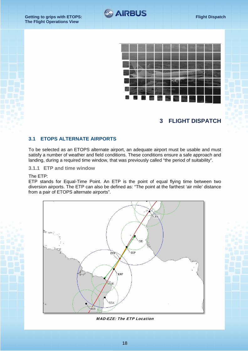
3.1.1 ETP and time window The ETP: ETP stands for Equal-Time Point. An ETP is the point of equal flying time between two diversion airports. The ETP can also be defined as: “The point at the farthest ‘air mile’ distance from a pair of ETOPS alternate airports”.
MAD-EZE: The ETP Location
Getting to grips with ETOPS: Flight Dispatch The Flight Operations View
19
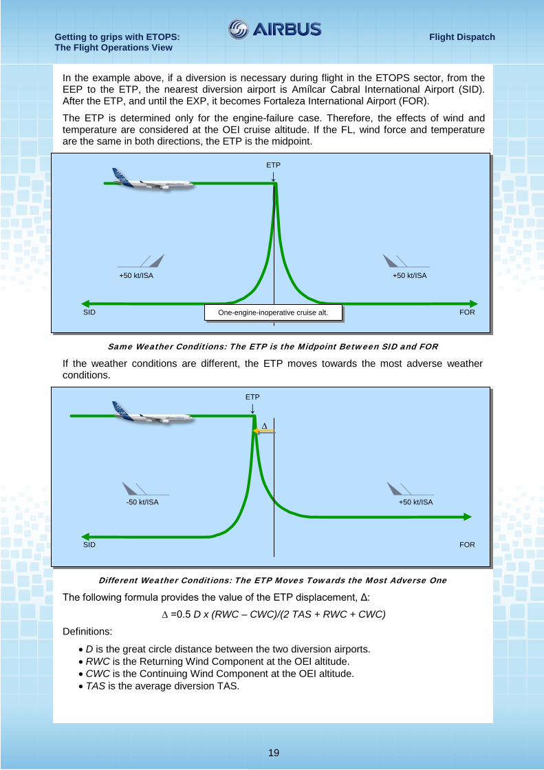
In the example above, if a diversion is necessary during flight in the ETOPS sector, from the EEP to the ETP, the nearest diversion airport is Amílcar Cabral International Airport (SID). After the ETP, and until the EXP, it becomes Fortaleza International Airport (FOR).
The ETP is determined only for the engine-failure case. Therefore, the effects of wind and temperature are considered at the OEI cruise altitude. If the FL, wind force and temperature are the same in both directions, the ETP is the midpoint.
Same Weather Conditions: The ETP is the Midpoint Between SID and FOR
If the weather conditions are different, the ETP moves towards the most adverse weather conditions.
Different Weather Conditions: The ETP Moves Towards the Most Adverse One
The following formula provides the value of the ETP displacement, Δ:
∆ =0.5 D x (RWC – CWC)/(2 TAS + RWC + CWC)
Definitions:
• D is the great circle distance between the two diversion airports. • RWC is the Returning Wind Component at the OEI altitude. • CWC is the Continuing Wind Component at the OEI altitude. • TAS is the average diversion TAS.
ETP ↓
SID FOR One-engine-inoperative cruise alt.
+50 kt/ISA +50 kt/ISA
ETP ↓
+50 kt/ISA -50 kt/ISA
SID FOR
∆
Getting to grips with ETOPS: Flight Dispatch The Flight Operations View
20
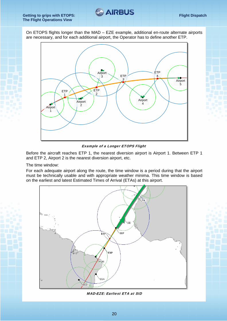
On ETOPS flights longer than the MAD – EZE example, additional en-route alternate airports are necessary, and for each additional airport, the Operator has to define another ETP.
Example of a Longer ETOPS Flight
Before the aircraft reaches ETP 1, the nearest diversion airport is Airport 1. Between ETP 1 and ETP 2, Airport 2 is the nearest diversion airport, etc.
The time window: For each adequate airport along the route, the time window is a period during that the airport must be technically usable and with appropriate weather minima. This time window is based on the earliest and latest Estimated Times of Arrival (ETAs) at this airport.
MAD-EZE: Earliest ETA at SID
Airport 1
Airport 2
Airport 3
Airport 4
Airport 5
ETP 1
ETP 2
ETP 3
ETP 4
Getting to grips with ETOPS: Flight Dispatch The Flight Operations View
21
For SID, we use the EEP to calculate the earliest ETA, because it is the point where ETOPS begin. Before the EEP, the usual 60 min regulations apply.
The estimated time of departure + The flight time to the EEP (Normal cruise) + The flight time from the EEP to SID (Normal cruise speed and FL) = The earliest ETA at SID
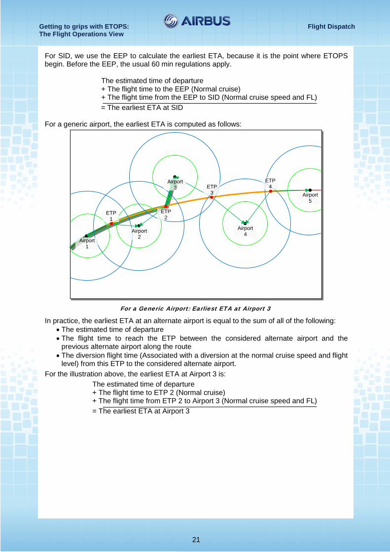
For a generic airport, the earliest ETA is computed as follows:
For a Generic Airport: Earliest ETA at Airport 3
In practice, the earliest ETA at an alternate airport is equal to the sum of all of the following: • The estimated time of departure • The flight time to reach the ETP between the considered alternate airport and the
previous alternate airport along the route • The diversion flight time (Associated with a diversion at the normal cruise speed and flight
level) from this ETP to the considered alternate airport. For the illustration above, the earliest ETA at Airport 3 is:
The estimated time of departure + The flight time to ETP 2 (Normal cruise) + The flight time from ETP 2 to Airport 3 (Normal cruise speed and FL) = The earliest ETA at Airport 3
Airport 1
Airport 2
Airport 3
Airport 4
Airport 5
ETP 1
ETP 2
ETP 3
ETP 4
Getting to grips with ETOPS: Flight Dispatch The Flight Operations View
22
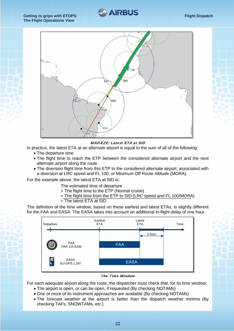
MAD-EZE: Latest ETA at SID
In practice, the latest ETA at an alternate airport is equal to the sum of all of the following: • The departure time • The flight time to reach the ETP between the considered alternate airport and the next
alternate airport along the route • The diversion flight time from this ETP to the considered alternate airport, associated with
a diversion at LRC speed and FL 100, or Minimum Off Route Altitude (MORA). For the example above, the latest ETA at SID is:
The estimated time of departure + The flight time to the ETP (Normal cruise) + The flight time from the ETP to SID (LRC speed and FL 100/MORA) = The latest ETA at SID
The definition of the time window, based on these earliest and latest ETAs, is slightly different for the FAA and EASA: The EASA takes into account an additional in-flight delay of one hour.
The Time Window
For each adequate airport along the route, the dispatcher must check that, for its time window: • The airport is open, or can be open, if requested (By checking NOTAMs) • One or more of its instrument approaches are available (By checking NOTAMs) • The forecast weather at the airport is better than the dispatch weather minima (By
checking TAFs, SNOWTAMs, etc.)
Departure Time Earliest
ETA Latest ETA
1 hour
FAA
EASA
FAA FAR 121.624b
EASA EU-OPS 1.297
Getting to grips with ETOPS: Flight Dispatch The Flight Operations View
23
The time window is provided for the estimated time of departure, and must be adjusted to the actual time of departure, in the case of a delay:
• For EASA Operators: Airbus recommends that if the dispatch of a flight is delayed by more than one hour, pilots and/or operations personnel should monitor weather forecasts and airport status of the ETOPS alternate airports, to ensure that they remain within the specified planning minima requirements, until dispatch.
• For FAA Operators: Pilots and/or operations personnel should monitor weather forecasts and airport status of the ETOPS alternate airports, to ensure that they remain within the specified planning minima requirements, until dispatch.
3.1.2 Dispatch weather minima The dispatch weather minima for the ETOPS alternate airports are usually more restrictive than the normal weather minima necessary to initiate an instrument approach. This is due to the following two main factors:
• The possible degradation of weather conditions • The need to determine the suitability (During the above-mentioned time window) of a
specific en-route alternate airport, before departure of the ETOPS flight.
These more restrictive minima are necessary to ensure that the flight crew can safely perform an instrument approach, in the case of a diversion to the corresponding alternate airport.
These ETOPS dispatch minima apply only until the aircraft is airborne. After takeoff, the normal minima apply.
The ETOPS dispatch weather minima may be slightly different from one regulation to another:
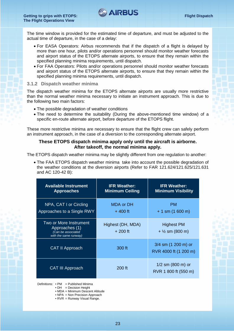
• The FAA ETOPS dispatch weather minima take into account the possible degradation of the weather conditions at the diversion airports (Refer to FAR 121.624/121.625/121.631 and AC 120-42 B):
Available Instrument Approaches
IFR Weather: Minimum Ceiling
IFR Weather: Minimum Visibility
NPA, CAT I or Circling Approaches to a Single RWY
MDA or DH + 400 ft
PM + 1 sm (1 600 m)
Two or More Instrument Approaches (1) (Can be associated
with the same runway)
Highest (DH, MDA) + 200 ft
Highest PM + ½ sm (800 m)
CAT II Approach 300 ft 3/4 sm (1 200 m) or
RVR 4000 ft (1 200 m)
CAT III Approach 200 ft 1/2 sm (800 m) or
RVR 1 800 ft (550 m)
Definitions: • PM = Published Minima • DH = Decision Height • MDA = Minimum Descent Altitude • NPA = Non Precision Approach • RVR = Runway Visual Range.
Getting to grips with ETOPS: Flight Dispatch The Flight Operations View
24
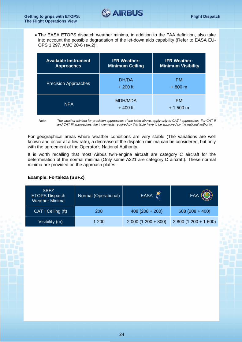
• The EASA ETOPS dispatch weather minima, in addition to the FAA definition, also take into account the possible degradation of the let-down aids capability (Refer to EASA EU-OPS 1.297, AMC 20-6 rev.2):
Available Instrument Approaches
IFR Weather: Minimum Ceiling
IFR Weather: Minimum Visibility
Precision Approaches DH/DA + 200 ft
PM + 800 m
NPA MDH/MDA
+ 400 ft PM
+ 1 500 m
Note: The weather minima for precision approaches of the table above, apply only to CAT I approaches. For CAT II
and CAT III approaches, the increments required by this table have to be approved by the national authority.
For geographical areas where weather conditions are very stable (The variations are well known and occur at a low rate), a decrease of the dispatch minima can be considered, but only with the agreement of the Operator’s National Authority.
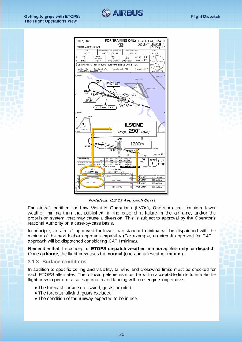
It is worth recalling that most Airbus twin-engine aircraft are category C aircraft for the determination of the normal minima (Only some A321 are category D aircraft). These normal minima are provided on the approach plates.
Example: Fortaleza (SBFZ)
SBFZ ETOPS Dispatch Weather Minima
Normal (Operational) EASA FAA
CAT I Ceiling (ft) 208 408 (208 + 200) 608 (208 + 400)
Visibility (m) 1 200 2 000 (1 200 + 800) 2 800 (1 200 + 1 600)
Getting to grips with ETOPS: Flight Dispatch The Flight Operations View
25
Fortaleza, ILS 13 Approach Chart
For aircraft certified for Low Visibility Operations (LVOs), Operators can consider lower weather minima than that published, in the case of a failure in the airframe, and/or the propulsion system, that may cause a diversion. This is subject to approval by the Operator’s National Authority on a case-by-case basis.
In principle, an aircraft approved for lower-than-standard minima will be dispatched with the minima of the next higher approach capability (For example, an aircraft approved for CAT II approach will be dispatched considering CAT I minima).
Remember that this concept of ETOPS dispatch weather minima applies only for dispatch: Once airborne, the flight crew uses the normal (operational) weather minima.
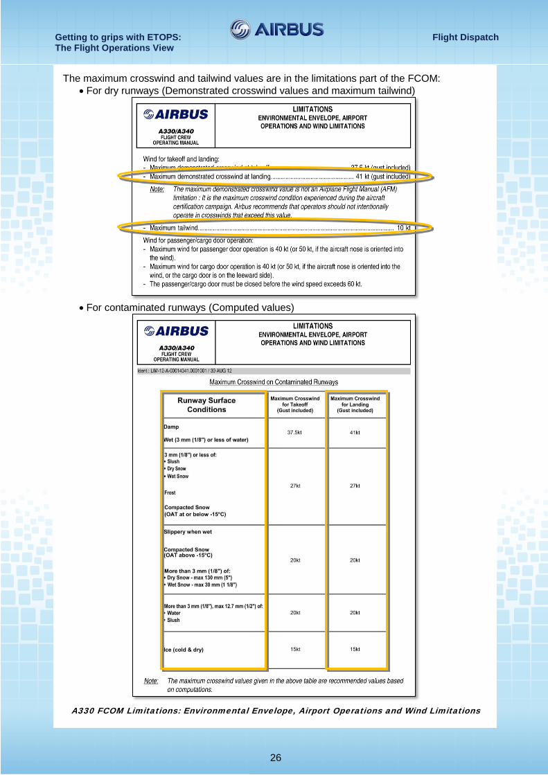
3.1.3 Surface conditions In addition to specific ceiling and visibility, tailwind and crosswind limits must be checked for each ETOPS alternates. The following elements must be within acceptable limits to enable the flight crew to perform a safe approach and landing with one engine inoperative:
• The forecast surface crosswind, gusts included • The forecast tailwind, gusts excluded • The condition of the runway expected to be in use.
1200m
ILS/DME DA(H) 290’ (208’)
Getting to grips with ETOPS: Flight Dispatch The Flight Operations View
26
The maximum crosswind and tailwind values are in the limitations part of the FCOM: • For dry runways (Demonstrated crosswind values and maximum tailwind)
• For contaminated runways (Computed values)
A330 FCOM Limitations: Environmental Envelope, Airport Operations and Wind Limitations
Getting to grips with ETOPS: Flight Dispatch The Flight Operations View
27
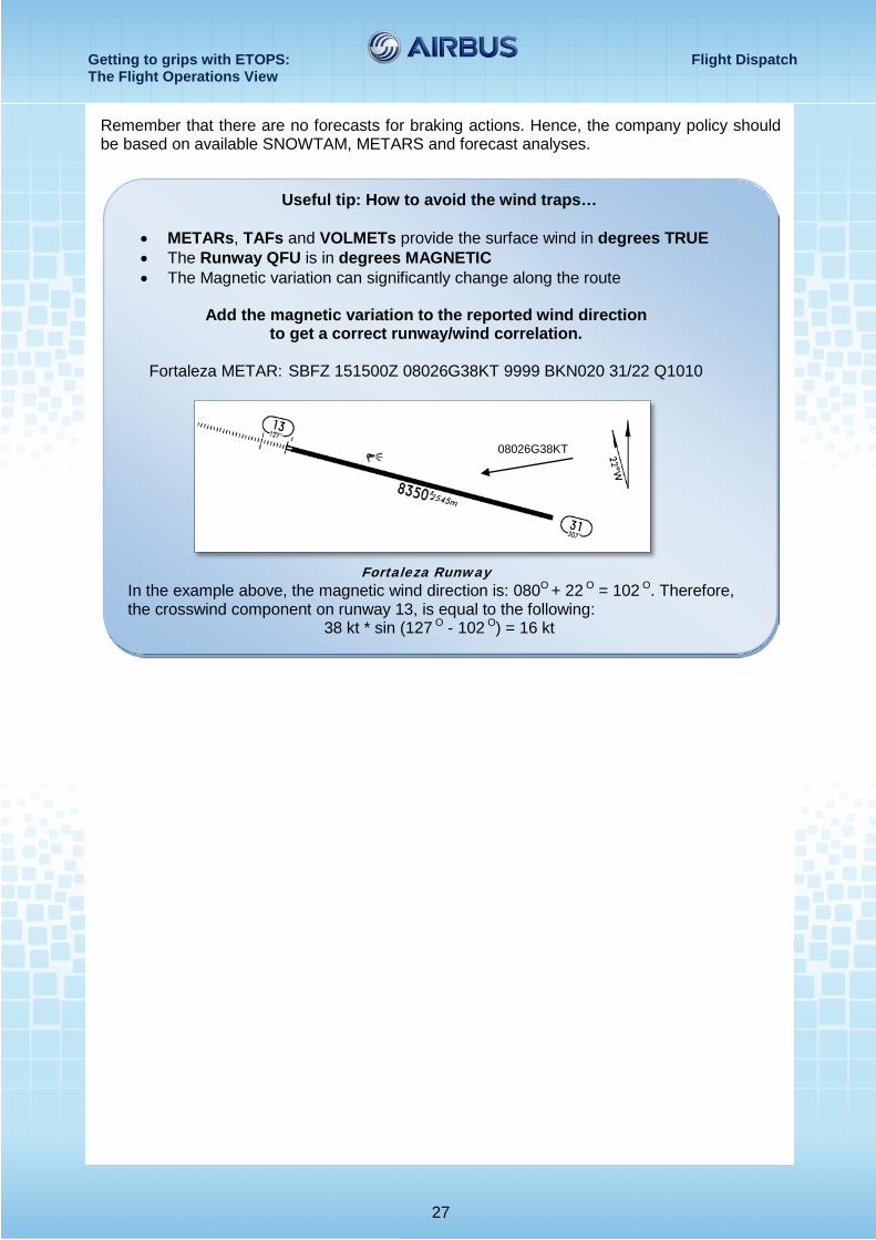
Remember that there are no forecasts for braking actions. Hence, the company policy should be based on available SNOWTAM, METARS and forecast analyses.
Useful tip: How to avoid the wind traps…
• METARs, TAFs and VOLMETs provide the surface wind in degrees TRUE • The Runway QFU is in degrees MAGNETIC • The Magnetic variation can significantly change along the route
Add the magnetic variation to the reported wind direction
to get a correct runway/wind correlation.
Fortaleza METAR: SBFZ 151500Z 08026G38KT 9999 BKN020 31/22 Q1010
Fortaleza Runway
In the example above, the magnetic wind direction is: 080O + 22 O = 102 O. Therefore, the crosswind component on runway 13, is equal to the following:
38 kt * sin (127 O - 102 O) = 16 kt
08026G38KT
Getting to grips with ETOPS: Flight Dispatch The Flight Operations View
28
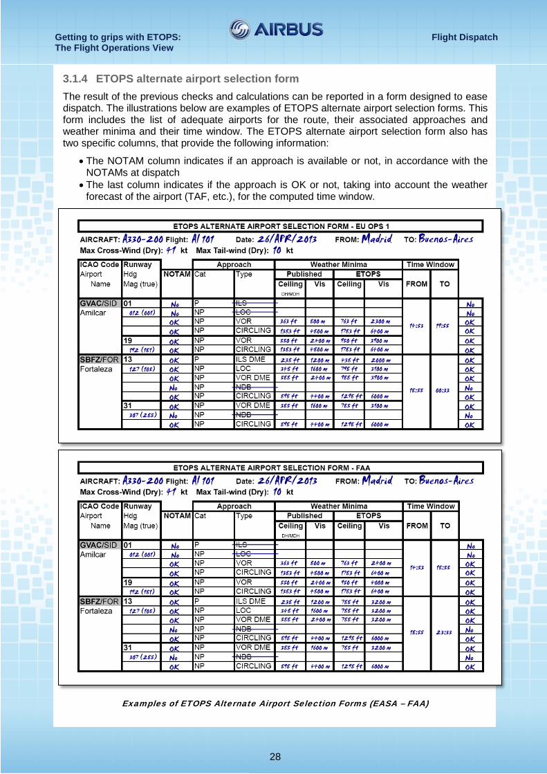
3.1.4 ETOPS alternate airport selection form The result of the previous checks and calculations can be reported in a form designed to ease dispatch. The illustrations below are examples of ETOPS alternate airport selection forms. This form includes the list of adequate airports for the route, their associated approaches and weather minima and their time window. The ETOPS alternate airport selection form also has two specific columns, that provide the following information:
• The NOTAM column indicates if an approach is available or not, in accordance with the NOTAMs at dispatch
• The last column indicates if the approach is OK or not, taking into account the weather forecast of the airport (TAF, etc.), for the computed time window.
Examples of ETOPS Alternate Airport Selection Forms (EASA – FAA)
Getting to grips with ETOPS: Flight Dispatch The Flight Operations View
29
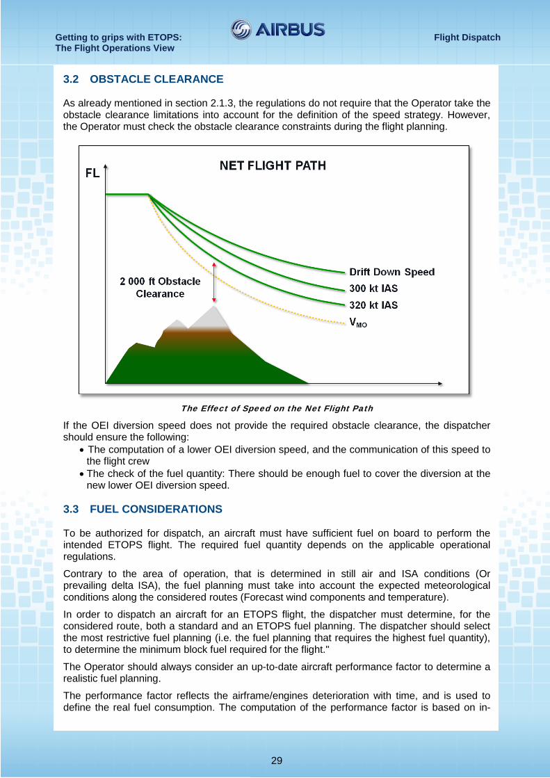
3.2 OBSTACLE CLEARANCE As already mentioned in section 2.1.3, the regulations do not require that the Operator take the obstacle clearance limitations into account for the definition of the speed strategy. However, the Operator must check the obstacle clearance constraints during the flight planning.
The Effect of Speed on the Net Flight Path
If the OEI diversion speed does not provide the required obstacle clearance, the dispatcher should ensure the following:
• The computation of a lower OEI diversion speed, and the communication of this speed to the flight crew
• The check of the fuel quantity: There should be enough fuel to cover the diversion at the new lower OEI diversion speed.
3.3 FUEL CONSIDERATIONS
To be authorized for dispatch, an aircraft must have sufficient fuel on board to perform the intended ETOPS flight. The required fuel quantity depends on the applicable operational regulations.
Contrary to the area of operation, that is determined in still air and ISA conditions (Or prevailing delta ISA), the fuel planning must take into account the expected meteorological conditions along the considered routes (Forecast wind components and temperature).
In order to dispatch an aircraft for an ETOPS flight, the dispatcher must determine, for the considered route, both a standard and an ETOPS fuel planning. The dispatcher should select the most restrictive fuel planning (i.e. the fuel planning that requires the highest fuel quantity), to determine the minimum block fuel required for the flight."
The Operator should always consider an up-to-date aircraft performance factor to determine a realistic fuel planning.
The performance factor reflects the airframe/engines deterioration with time, and is used to define the real fuel consumption. The computation of the performance factor is based on in-
Getting to grips with ETOPS: Flight Dispatch The Flight Operations View
30
flight recordings (Manual or automatic) of engine and aircraft parameters. Therefore, for a new aircraft, whose performance is equivalent to the baseline, the performance factor is equal to one. The performance factor should be defined for each individual aircraft of the Operator's fleet. The FCOM and the in-flight performance computer programs (IFP and FLIP) provide the fuel consumption data for a baseline aircraft. To determine the real fuel consumption, the baseline data should be multiplied by the performance factor. For example, a performance factor equal to 1.03 indicates a 3 % increase in the fuel consumption. This fuel planning is the one used for non-ETOPS operations. Therefore, the standard block (Ramp) fuel includes all of the following fuel quantities:
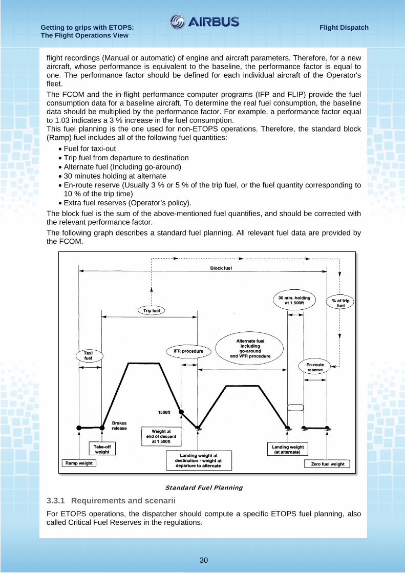
• Fuel for taxi-out • Trip fuel from departure to destination • Alternate fuel (Including go-around) • 30 minutes holding at alternate • En-route reserve (Usually 3 % or 5 % of the trip fuel, or the fuel quantity corresponding to
10 % of the trip time) • Extra fuel reserves (Operator’s policy).
The block fuel is the sum of the above-mentioned fuel quantifies, and should be corrected with the relevant performance factor. The following graph describes a standard fuel planning. All relevant fuel data are provided by the FCOM.
Standard Fuel Planning
3.3.1 Requirements and scenarii For ETOPS operations, the dispatcher should compute a specific ETOPS fuel planning, also called Critical Fuel Reserves in the regulations.
Getting to grips with ETOPS: Flight Dispatch The Flight Operations View
31
The ETOPS fuel planning has two parts: The first part corresponds to a standard fuel scenario from the departure airport to the Critical Point (CP) and the second part corresponds to the critical fuel scenario from the CP to the diversion airport.
The ETOPS critical fuel scenario is based on the separate study of three failure cases, that occur at the critical point, with their respective diversion profiles.
Critical fuel scenario This scenario is based on a case that occurs at the CP, and that requires a diversion.
The diversion profile is defined as follows:
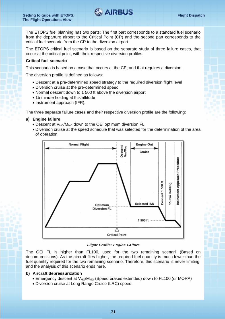
• Descent at a pre-determined speed strategy to the required diversion flight level • Diversion cruise at the pre-determined speed • Normal descent down to 1 500 ft above the diversion airport • 15 minute holding at this altitude • Instrument approach (IFR).
The three separate failure cases and their respective diversion profile are the following:
a) Engine failure • Descent at VMO/MMO down to the OEI optimum diversion FL, • Diversion cruise at the speed schedule that was selected for the determination of the area
of operation.
Flight Profile: Engine Failure
The OEI FL is higher than FL100, used for the two remaining scenarii (Based on decompressions). As the aircraft flies higher, the required fuel quantity is much lower than the fuel quantity required for the two remaining scenario. Therefore, this scenario is never limiting, and the analysis of this scenario ends here.
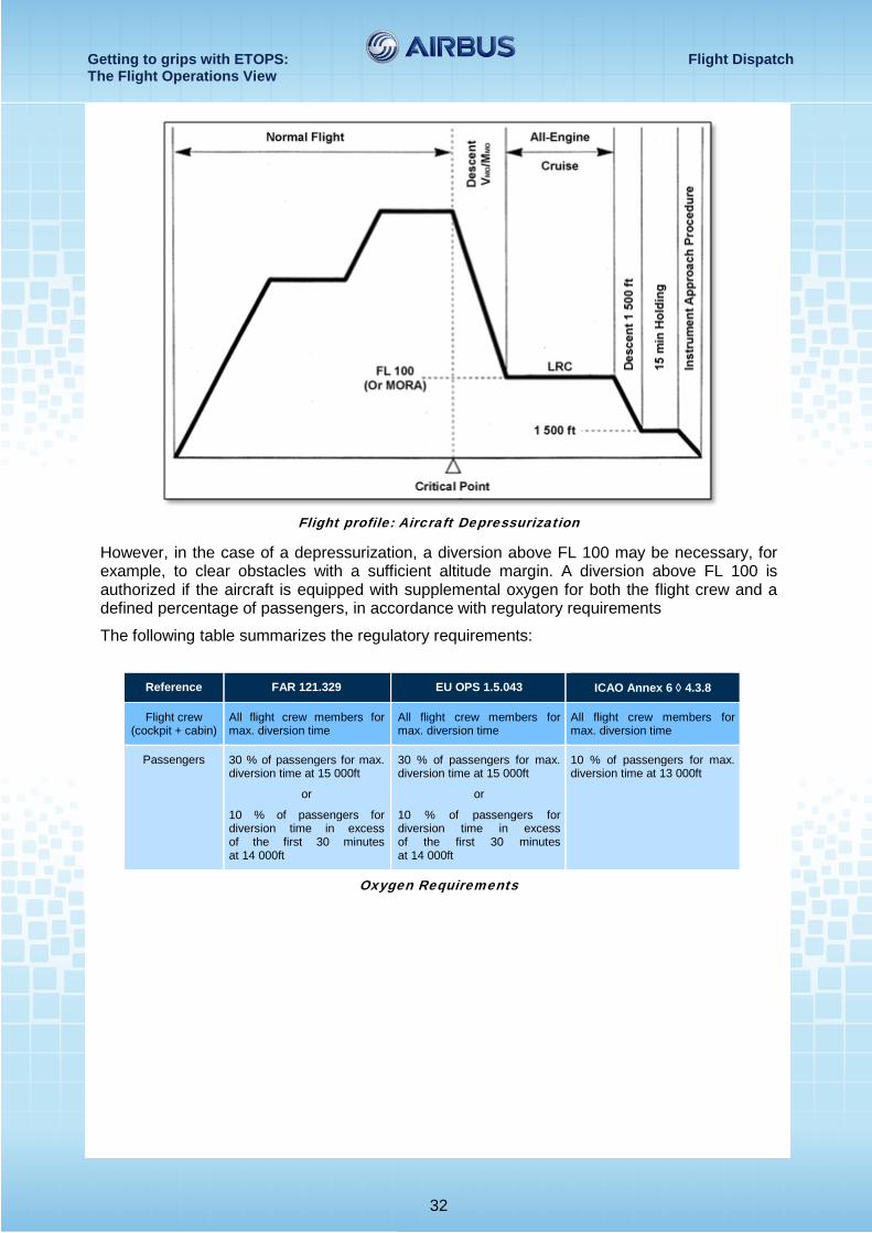
b) Aircraft depressurization • Emergency descent at VMO/MMO (Speed brakes extended) down to FL100 (or MORA) • Diversion cruise at Long Range Cruise (LRC) speed.
Getting to grips with ETOPS: Flight Dispatch The Flight Operations View
32
Flight profile: Aircraft Depressurization
However, in the case of a depressurization, a diversion above FL 100 may be necessary, for example, to clear obstacles with a sufficient altitude margin. A diversion above FL 100 is authorized if the aircraft is equipped with supplemental oxygen for both the flight crew and a defined percentage of passengers, in accordance with regulatory requirements
The following table summarizes the regulatory requirements:
Reference FAR 121.329 EU OPS 1.5.043 ICAO Annex 6 ◊ 4.3.8
Flight crew (cockpit + cabin)
All flight crew members for max. diversion time
All flight crew members for max. diversion time
All flight crew members for max. diversion time
Passengers 30 % of passengers for max. diversion time at 15 000ft
or
10 % of passengers for diversion time in excess of the first 30 minutes at 14 000ft
30 % of passengers for max. diversion time at 15 000ft
or
10 % of passengers for diversion time in excess of the first 30 minutes at 14 000ft
10 % of passengers for max. diversion time at 13 000ft
Oxygen Requirements
Getting to grips with ETOPS: Flight Dispatch The Flight Operations View
33
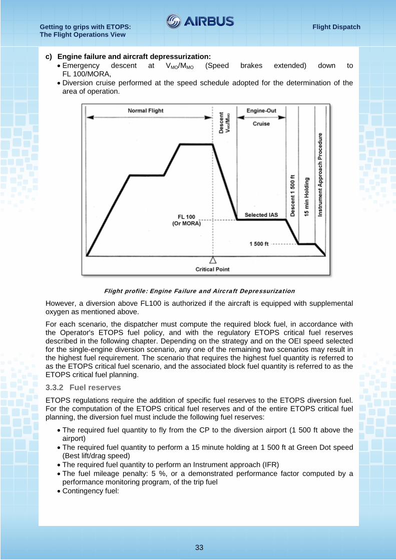
c) Engine failure and aircraft depressurization: • Emergency descent at VMO/MMO (Speed brakes extended) down to
FL 100/MORA, • Diversion cruise performed at the speed schedule adopted for the determination of the
area of operation.
Flight profile: Engine Failure and Aircraft Depressurization
However, a diversion above FL100 is authorized if the aircraft is equipped with supplemental oxygen as mentioned above.
For each scenario, the dispatcher must compute the required block fuel, in accordance with the Operator's ETOPS fuel policy, and with the regulatory ETOPS critical fuel reserves described in the following chapter. Depending on the strategy and on the OEI speed selected for the single-engine diversion scenario, any one of the remaining two scenarios may result in the highest fuel requirement. The scenario that requires the highest fuel quantity is referred to as the ETOPS critical fuel scenario, and the associated block fuel quantity is referred to as the ETOPS critical fuel planning.
3.3.2 Fuel reserves ETOPS regulations require the addition of specific fuel reserves to the ETOPS diversion fuel. For the computation of the ETOPS critical fuel reserves and of the entire ETOPS critical fuel planning, the diversion fuel must include the following fuel reserves:
• The required fuel quantity to fly from the CP to the diversion airport (1 500 ft above the airport)
• The required fuel quantity to perform a 15 minute holding at 1 500 ft at Green Dot speed (Best lift/drag speed)
• The required fuel quantity to perform an Instrument approach (IFR) • The fuel mileage penalty: 5 %, or a demonstrated performance factor computed by a
performance monitoring program, of the trip fuel • Contingency fuel:
Getting to grips with ETOPS: Flight Dispatch The Flight Operations View
34
o The required fuel quantity to account for a 5 % increase in the forecast wind, if this forecast wind is based on a wind model validated by the Authority, e.g. the World Area Forecast System (WAFS), or
o 5 % of the required fuel quantity to fly from the CP to the diversion airport, • Effect of any CDL and/or MEL item • Icing: The fuel to account for icing must compensate for the additional fuel consumption
due to the most restrictive of the following effects: o The effect of the use of Nacelle Anti-Ice (NAI) + Wing Anti-Ice (WAI) systems
during the entire time icing is forecast, or o The effect of ice accretion on the unheated surfaces of the aircraft (Additional
drag) plus the effect of the use of NAI and WAI for 10 % of the time icing is forecast.
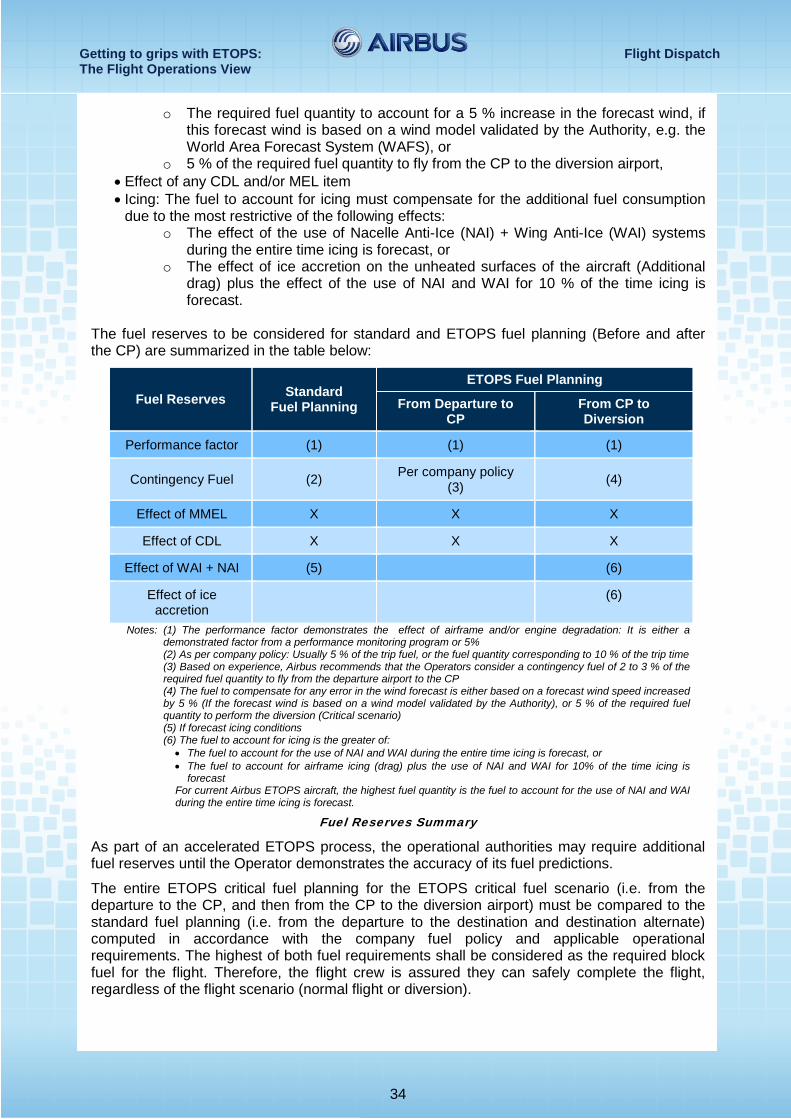
The fuel reserves to be considered for standard and ETOPS fuel planning (Before and after the CP) are summarized in the table below:
Fuel Reserves Standard Fuel Planning
ETOPS Fuel Planning
From Departure to CP
From CP to Diversion
Performance factor (1) (1) (1)
Contingency Fuel (2) Per company policy (3) (4)
Effect of MMEL X X X
Effect of CDL X X X
Effect of WAI + NAI (5) (6)
Effect of ice accretion (6)
Notes: (1) The performance factor demonstrates the effect of airframe and/or engine degradation: It is either a demonstrated factor from a performance monitoring program or 5%
(2) As per company policy: Usually 5 % of the trip fuel, or the fuel quantity corresponding to 10 % of the trip time (3) Based on experience, Airbus recommends that the Operators consider a contingency fuel of 2 to 3 % of the
required fuel quantity to fly from the departure airport to the CP (4) The fuel to compensate for any error in the wind forecast is either based on a forecast wind speed increased
by 5 % (If the forecast wind is based on a wind model validated by the Authority), or 5 % of the required fuel quantity to perform the diversion (Critical scenario)
(5) If forecast icing conditions (6) The fuel to account for icing is the greater of:
• The fuel to account for the use of NAI and WAI during the entire time icing is forecast, or • The fuel to account for airframe icing (drag) plus the use of NAI and WAI for 10% of the time icing is
forecast For current Airbus ETOPS aircraft, the highest fuel quantity is the fuel to account for the use of NAI and WAI during the entire time icing is forecast.
Fuel Reserves Summary
As part of an accelerated ETOPS process, the operational authorities may require additional fuel reserves until the Operator demonstrates the accuracy of its fuel predictions.
The entire ETOPS critical fuel planning for the ETOPS critical fuel scenario (i.e. from the departure to the CP, and then from the CP to the diversion airport) must be compared to the standard fuel planning (i.e. from the departure to the destination and destination alternate) computed in accordance with the company fuel policy and applicable operational requirements. The highest of both fuel requirements shall be considered as the required block fuel for the flight. Therefore, the flight crew is assured they can safely complete the flight, regardless of the flight scenario (normal flight or diversion).
Getting to grips with ETOPS: Flight Dispatch The Flight Operations View
35
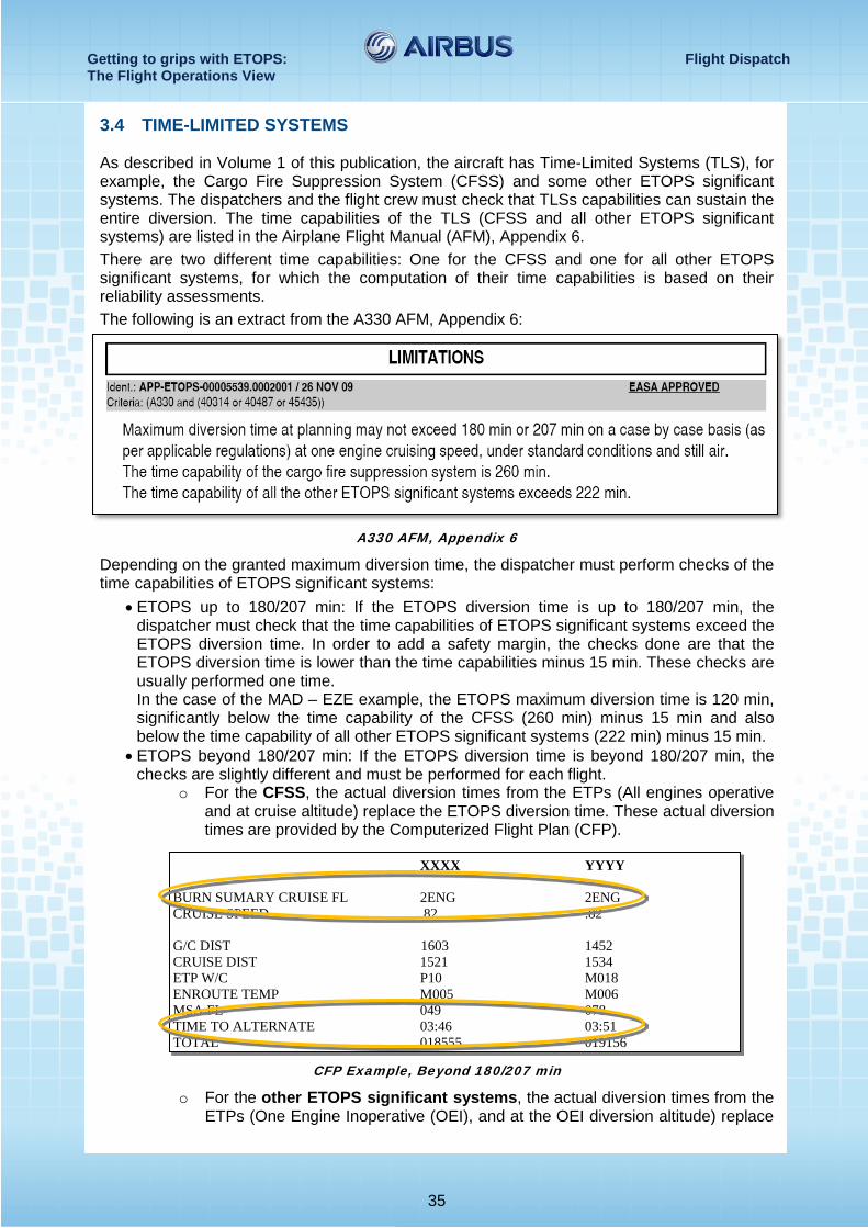
3.4 TIME-LIMITED SYSTEMS As described in Volume 1 of this publication, the aircraft has Time-Limited Systems (TLS), for example, the Cargo Fire Suppression System (CFSS) and some other ETOPS significant systems. The dispatchers and the flight crew must check that TLSs capabilities can sustain the entire diversion. The time capabilities of the TLS (CFSS and all other ETOPS significant systems) are listed in the Airplane Flight Manual (AFM), Appendix 6. There are two different time capabilities: One for the CFSS and one for all other ETOPS significant systems, for which the computation of their time capabilities is based on their reliability assessments. The following is an extract from the A330 AFM, Appendix 6:
A330 AFM, Appendix 6
Depending on the granted maximum diversion time, the dispatcher must perform checks of the time capabilities of ETOPS significant systems:
• ETOPS up to 180/207 min: If the ETOPS diversion time is up to 180/207 min, the dispatcher must check that the time capabilities of ETOPS significant systems exceed the ETOPS diversion time. In order to add a safety margin, the checks done are that the ETOPS diversion time is lower than the time capabilities minus 15 min. These checks are usually performed one time. In the case of the MAD – EZE example, the ETOPS maximum diversion time is 120 min, significantly below the time capability of the CFSS (260 min) minus 15 min and also below the time capability of all other ETOPS significant systems (222 min) minus 15 min.
• ETOPS beyond 180/207 min: If the ETOPS diversion time is beyond 180/207 min, the checks are slightly different and must be performed for each flight.
o For the CFSS, the actual diversion times from the ETPs (All engines operative and at cruise altitude) replace the ETOPS diversion time. These actual diversion times are provided by the Computerized Flight Plan (CFP).
CFP Example, Beyond 180/207 min
o For the other ETOPS significant systems, the actual diversion times from the ETPs (One Engine Inoperative (OEI), and at the OEI diversion altitude) replace
XXXX YYYY BURN SUMARY CRUISE FL 2ENG 2ENG CRUISE SPEED .82 .82 G/C DIST 1603 1452 CRUISE DIST 1521 1534 ETP W/C P10 M018 ENROUTE TEMP M005 M006 MSA FL 049 078 TIME TO ALTERNATE 03:46 03:51 TOTAL 018555 019156
Getting to grips with ETOPS: Flight Dispatch The Flight Operations View
36
the ETOPS diversion time. Note that these actual OEI diversion times can be longer than the ETOPS diversion time. OEI diversion times are also in the CFP.
CFP Example, Beyond 180/207 min
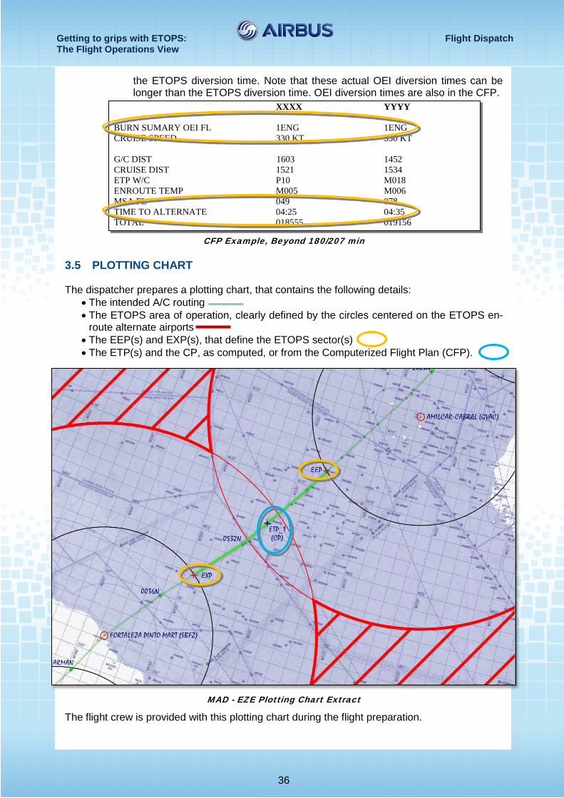
3.5 PLOTTING CHART The dispatcher prepares a plotting chart, that contains the following details:
• The intended A/C routing • The ETOPS area of operation, clearly defined by the circles centered on the ETOPS en-
route alternate airports • The EEP(s) and EXP(s), that define the ETOPS sector(s) • The ETP(s) and the CP, as computed, or from the Computerized Flight Plan (CFP).
MAD - EZE Plotting Chart Extract
The flight crew is provided with this plotting chart during the flight preparation.
XXXX YYYY BURN SUMARY OEI FL 1ENG 1ENG CRUISE SPEED 330 KT 330 KT G/C DIST 1603 1452 CRUISE DIST 1521 1534 ETP W/C P10 M018 ENROUTE TEMP M005 M006 MSA FL 049 078 TIME TO ALTERNATE 04:25 04:35 TOTAL 018555 019156
Getting to grips with ETOPS: Flight Dispatch The Flight Operations View
37
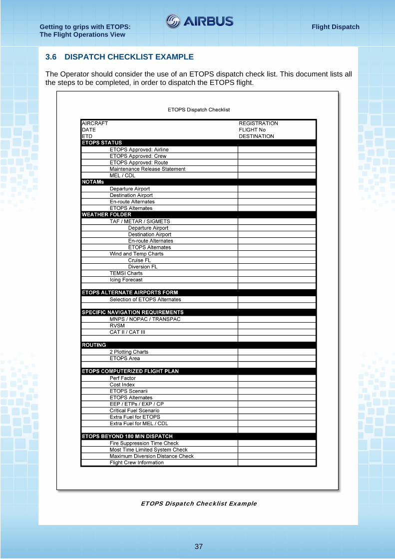
3.6 DISPATCH CHECKLIST EXAMPLE The Operator should consider the use of an ETOPS dispatch check list. This document lists all the steps to be completed, in order to dispatch the ETOPS flight.
ETOPS Dispatch Checklist Example
Getting to grips with ETOPS: Flight Dispatch The Flight Operations View
38
3.7 ETOPS BEYOND 180 MINUTES SPECIFICITIES As indicated in the example above, the ETOPS checklist includes the following specific checks for ETOPS beyond 180 min flights:
• The dispatcher and the flight crew must check that the requirements related to SATCOM are fulfilled (FAA only)
• The dispatcher and the flight crew must check the Time Limited Systems before each flight (Refer to section 3.4)
• The diversion distance must be below the granted Maximum Diversion Distance, if any. E.g. A330 Maximum Diversion Distance: 1 700 nm.
In addition to these specific checks, the dispatcher must inform the flight crew that the route is operated with ETOPS beyond 180 min.
Notes: The ETOPS 207 min certification (15 % extension of the ETOPS 180 min certification) is based on the requirements
of the ETOPS 180 min certification. Therefore, it is not considered as an ETOPS beyond 180 minutes certification.
Getting to grips with ETOPS: The ETOPS Flight The Flight Operations View
39
4 THE ETOPS FLIGHT
4.1 THE FLIGHT PREPARATION During the flight preparation, the dispatcher (or dispatch office) collects and processes the information described in the previous chapters of this publication. This information is provided to the flight crew in the following documents:
• A Computerized Flight Plan (CFP), also referred to as a Reference Flight Log (RFL), established with forecast en-route winds and temperatures
• Navigation and plotting charts, that describe the following: o The ETOPS area of operations defined by the relevant circles centered on the
ETOPS en-route alternate airports o The not authorized areas (Hatched) o The aircraft routing, that includes the EEP, EXP, ETPs and CP, based on the
prevailing wind conditions. The position of ETPs, based on the current wind forecast, is provided either by the CFP, or with a manual wind correction method.
• Airport charts, to perform a diversion to any ETOPS en-route alternate airports • The MEL and CDL ETOPS capability: Specific dispatch standards may apply and
depending on the status of the aircraft, additional fuel may be required • Relevant additional information:
o For the destination, destination alternate and ETOPS en-route alternate airports: NOTAMs, if any TAFs and METARs (The TAFs must be valid for the required time
windows in accordance with the CFP). o Significant weather charts that provide synoptic weather information and
forecast (e.g. turbulence and icing conditions) o Wind and temperature forecast charts for FL 100, for the typical single-engine
cruise altitude and for normal cruise flight levels. These charts may be used for icing forecast
o All other documents provided for a standard flight.
The flight crew then checks this documentation, and conducts a briefing that highlights any specific diversion strategy related to the route (Maximum diversion time, obstacle clearance,
Getting to grips with ETOPS: The ETOPS Flight The Flight Operations View
40
etc.) CFP fuel and time predictions are usually very accurate. However, the flight crew must also perform the following checks, to detect any possible gross error:
• Conformity of the CFP routing with the ATC flight plan • Aircraft type, date, Estimated Time of Departure (ETD), estimated ZFW/TOW/FOB • Wind data compared to the en-route weather forecast • Trip fuel, fuel to alternate, ETOPS fuel from ETPs to en-route alternates compared to
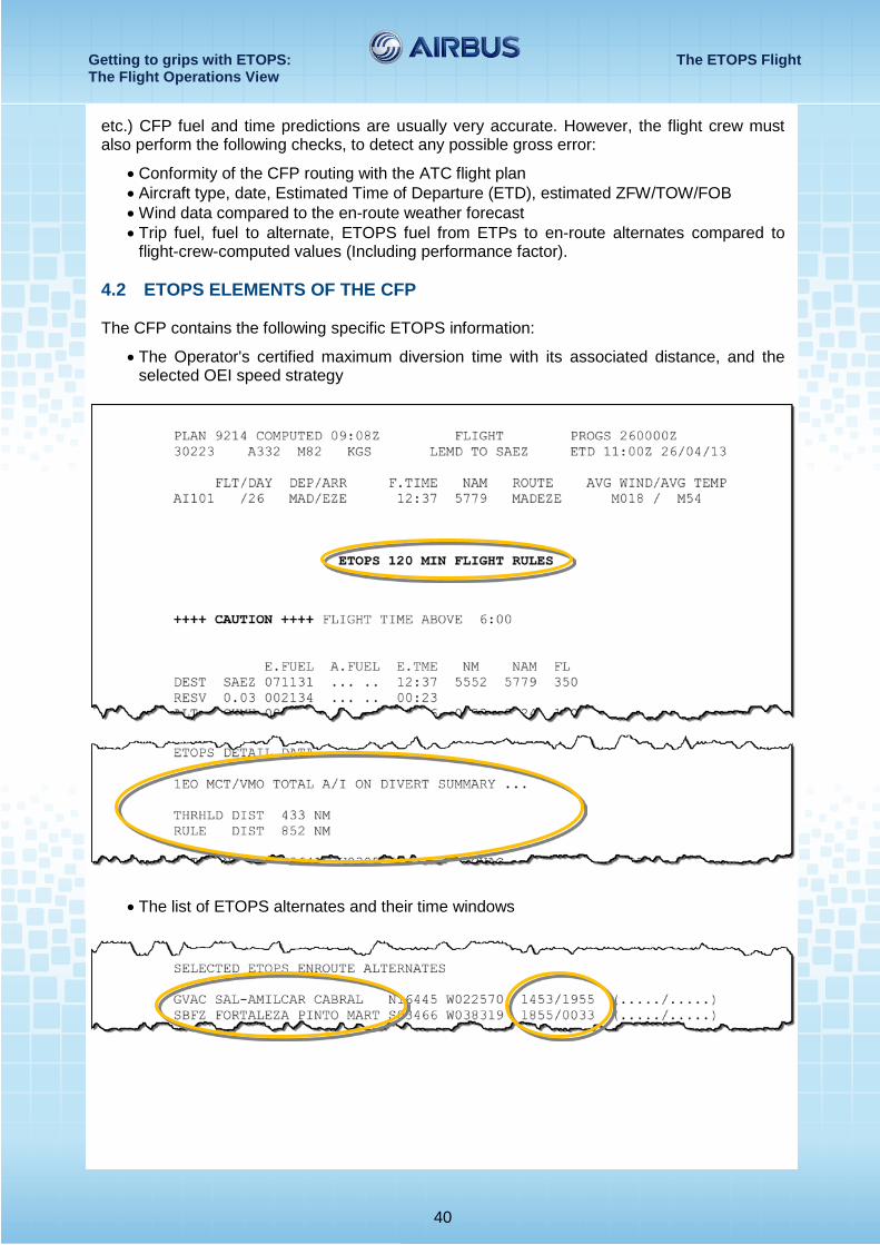
flight-crew-computed values (Including performance factor). 4.2 ETOPS ELEMENTS OF THE CFP The CFP contains the following specific ETOPS information:
• The Operator's certified maximum diversion time with its associated distance, and the selected OEI speed strategy
• The list of ETOPS alternates and their time windows
Getting to grips with ETOPS: The ETOPS Flight The Flight Operations View
41
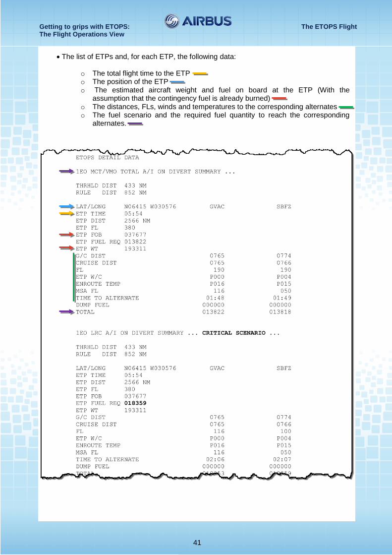
• The list of ETPs and, for each ETP, the following data:
o The total flight time to the ETP o The position of the ETP o The estimated aircraft weight and fuel on board at the ETP (With the
assumption that the contingency fuel is already burned) o The distances, FLs, winds and temperatures to the corresponding alternates o The fuel scenario and the required fuel quantity to reach the corresponding
alternates.
Getting to grips with ETOPS: The ETOPS Flight The Flight Operations View
42
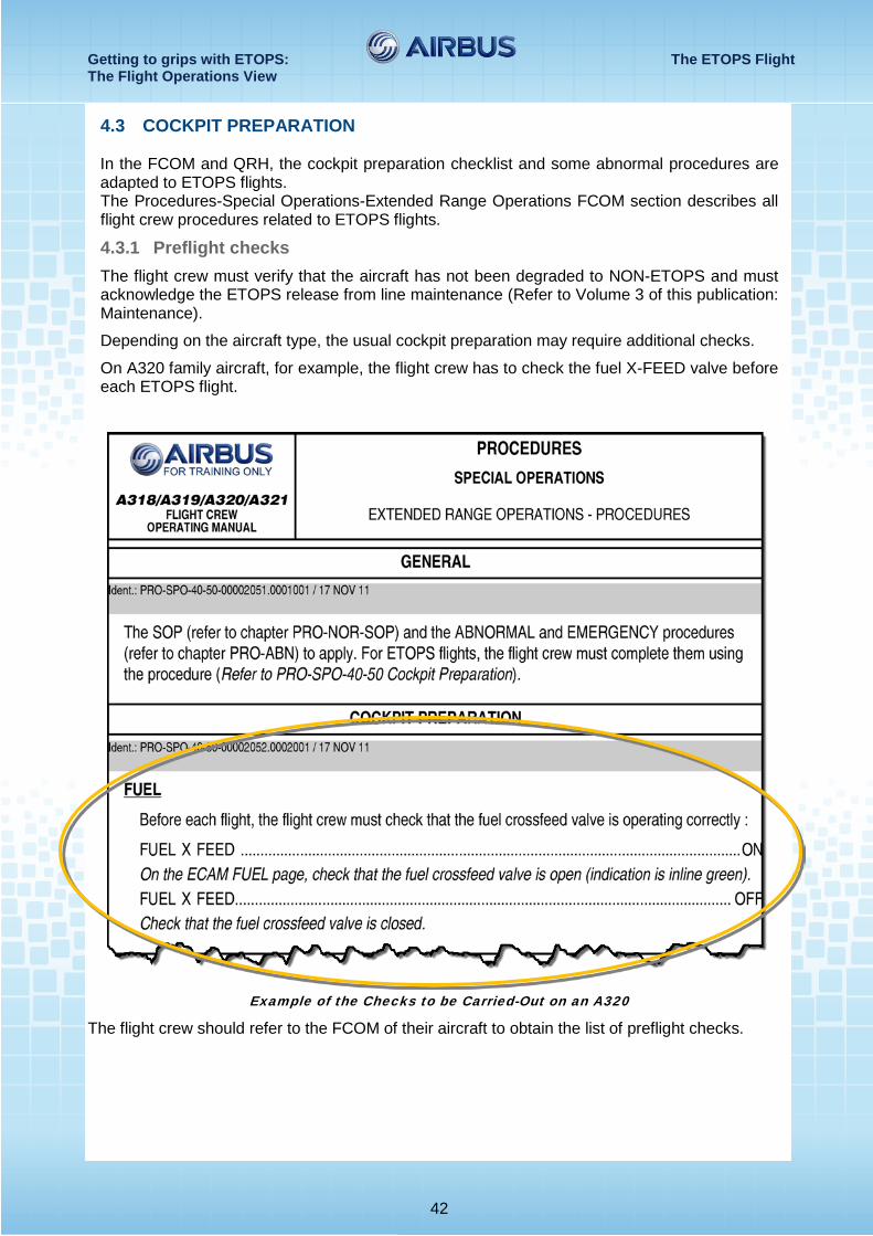
4.3 COCKPIT PREPARATION In the FCOM and QRH, the cockpit preparation checklist and some abnormal procedures are adapted to ETOPS flights. The Procedures-Special Operations-Extended Range Operations FCOM section describes all flight crew procedures related to ETOPS flights.
4.3.1 Preflight checks The flight crew must verify that the aircraft has not been degraded to NON-ETOPS and must acknowledge the ETOPS release from line maintenance (Refer to Volume 3 of this publication: Maintenance).
Depending on the aircraft type, the usual cockpit preparation may require additional checks.
On A320 family aircraft, for example, the flight crew has to check the fuel X-FEED valve before each ETOPS flight.
Example of the Checks to be Carried-Out on an A320
The flight crew should refer to the FCOM of their aircraft to obtain the list of preflight checks.
Getting to grips with ETOPS: The ETOPS Flight The Flight Operations View
43
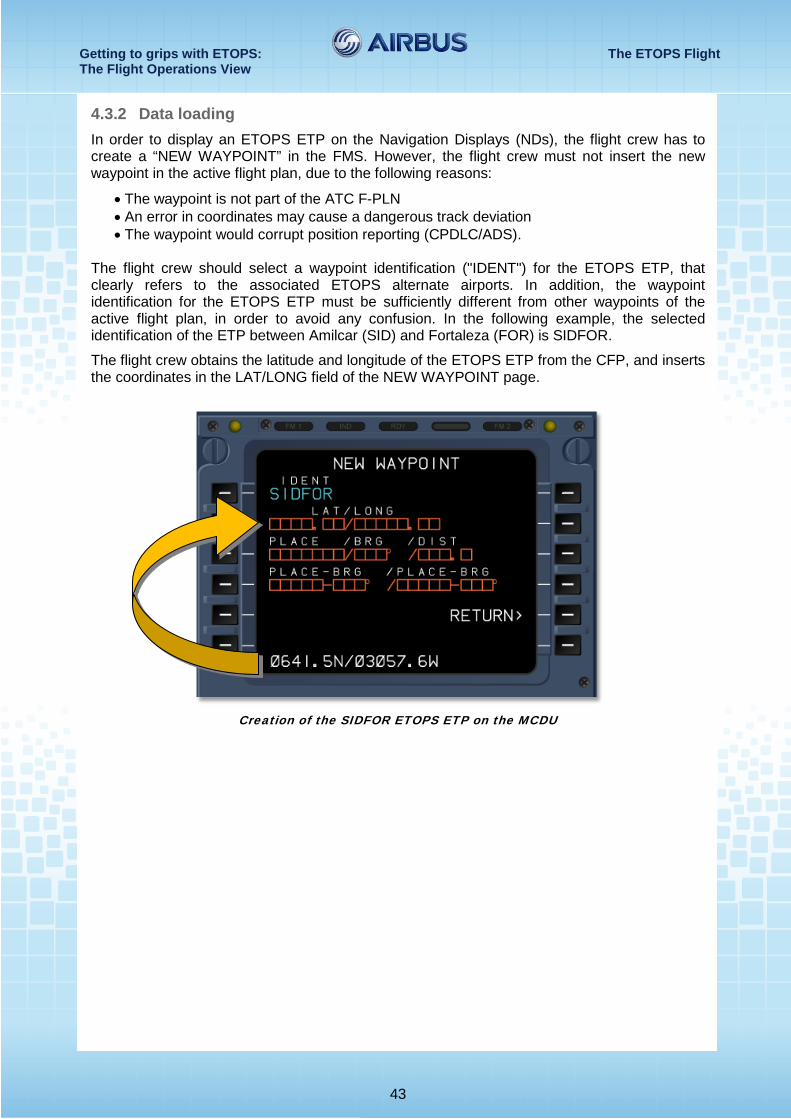
4.3.2 Data loading In order to display an ETOPS ETP on the Navigation Displays (NDs), the flight crew has to create a “NEW WAYPOINT” in the FMS. However, the flight crew must not insert the new waypoint in the active flight plan, due to the following reasons:
• The waypoint is not part of the ATC F-PLN • An error in coordinates may cause a dangerous track deviation • The waypoint would corrupt position reporting (CPDLC/ADS).
The flight crew should select a waypoint identification ("IDENT") for the ETOPS ETP, that clearly refers to the associated ETOPS alternate airports. In addition, the waypoint identification for the ETOPS ETP must be sufficiently different from other waypoints of the active flight plan, in order to avoid any confusion. In the following example, the selected identification of the ETP between Amilcar (SID) and Fortaleza (FOR) is SIDFOR.
The flight crew obtains the latitude and longitude of the ETOPS ETP from the CFP, and inserts the coordinates in the LAT/LONG field of the NEW WAYPOINT page.
Creation of the SIDFOR ETOPS ETP on the MCDU
Getting to grips with ETOPS: The ETOPS Flight The Flight Operations View
44
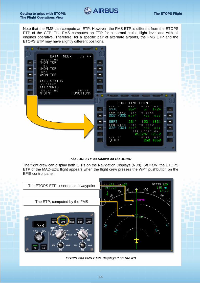
Note that the FMS can compute an ETP. However, the FMS ETP is different from the ETOPS ETP of the CFP. The FMS computes an ETP for a normal cruise flight level and with all engines operative. Therefore, for a specific pair of alternate airports, the FMS ETP and the ETOPS ETP may have slightly different positions.
The FMS ETP as Shown on the MCDU
The flight crew can display both ETPs on the Navigation Displays (NDs). SIDFOR, the ETOPS ETP of the MAD-EZE flight appears when the flight crew presses the WPT pushbutton on the EFIS control panel.
ETOPS and FMS ETPs Displayed on the ND
The ETOPS ETP, inserted as a waypoint
The ETP, computed by the FMS
Getting to grips with ETOPS: The ETOPS Flight The Flight Operations View
45
4.4 BEFORE REACHING THE EEP During the flight, the flight crew and the dispatcher must monitor the significant changes in conditions at the ETOPS alternate airports (Weather, NOTAMs, etc.)
Before the aircraft reaches the ETOPS Entry Point (EEP): • The weather conditions at all ETOPS alternate airports must satisfy the operating minima • If the weather conditions at any ETOPS alternate airport do not satisfy the operating
minima, the flight crew should select another ETOPS airport, select another route (if there is enough fuel on board), or turn back to the departure airport
• If an alternate airport becomes unavailable, and the flight crew selects another route, the dispatcher and the flight crew must check that the new route remains in the Operator's ETOPS area of operation.
The above-mentioned requirements do not override the authority of the pilot in command, who remains responsible for the selection of the safest course of action. However, the flight crew should not accept an ATC clearance that would cause the aircraft to fly a route beyond the Operator’s approved diversion time. 4.5 FLYING THE ETOPS SECTOR The flight crew should fly the ETOPS sector just as any other part of the flight, and perform the following:
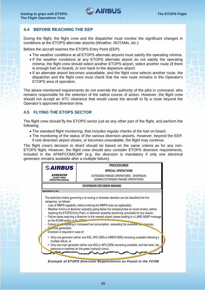
• The standard flight monitoring, that includes regular checks of the fuel on board. • The monitoring of the status of the various diversion airports. However, beyond the EEP,
if one diversion airport closes, or becomes unavailable, the flight may continue. The flight crew's decision to divert should be based on the same criteria as for any non-ETOPS flight. However, the flight crew should also consider ETOPS diversion requirements, included in the AFM/FCOM/CMP (e.g. the diversion is mandatory if only one electrical generator remains available after a multiple failure).
Example of ETOPS Diversion Requirements as Found in the FCOM
Getting to grips with ETOPS: The ETOPS Flight The Flight Operations View
46
4.6 DIVERSION As discussed in section 4.5 of this publication, the flight crew may have to divert, due to ETOPS requirements. However, there are no specific procedures for ETOPS diversions, i.e. the flight crew should perform an ETOPS diversion as any standard diversion. The flight crew still has to comply with route requirements (NAT, MNPS, etc.) as for non-ETOPS flights.
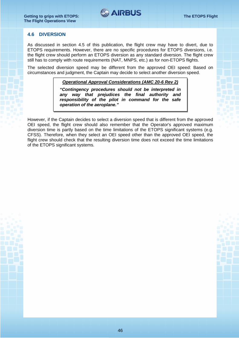
The selected diversion speed may be different from the approved OEI speed: Based on circumstances and judgment, the Captain may decide to select another diversion speed.
However, if the Captain decides to select a diversion speed that is different from the approved OEI speed, the flight crew should also remember that the Operator's approved maximum diversion time is partly based on the time limitations of the ETOPS significant systems (e.g. CFSS). Therefore, when they select an OEI speed other than the approved OEI speed, the flight crew should check that the resulting diversion time does not exceed the time limitations of the ETOPS significant systems.
Operational Approval Considerations (AMC 20-6 Rev 2) “Contingency procedures should not be interpreted in any way that prejudices the final authority and responsibility of the pilot in command for the safe operation of the aeroplane.”