epid exit dose qa arthur olch, phd, faapm - …amos3.aapm.org/abstracts/pdf/124-34840-405535... ·...
TRANSCRIPT

Emerging Technology: Real-Time Monitoring of Treatment Delivery
EPID Exit Dose QA
Arthur Olch, PhD, FAAPM AAPM Spring Clinical Meeting, March 21, 2017

Or……..
What Dose are the Patients Really Getting ???
Or…….
What Could Go Wrong?
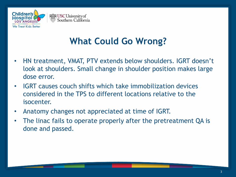
What Could Go Wrong?
• HN treatment, VMAT, PTV extends below shoulders. IGRT doesn’t
look at shoulders. Small change in shoulder position makes large
dose error.
• IGRT causes couch shifts which take immobilization devices
considered in the TPS to different locations relative to the
isocenter.
• Anatomy changes not appreciated at time of IGRT.
• The linac fails to operate properly after the pretreatment QA is
done and passed.
3

Conflict of Interest
• I am a Sun Nuclear Corporation beta site for PerFRACTION
• Note: Mention of any commercial product does not constitute an
endorsement
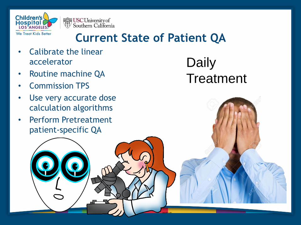
Current State of Patient QA • Calibrate the linear
accelerator
• Routine machine QA
• Commission TPS
• Use very accurate dose
calculation algorithms
• Perform Pretreatment
patient-specific QA
Daily
Treatment

The Ideal
• Gather information for every patient every fraction on the dose
they received that day and cumulate it daily
• Compare to planned dose and decide whether to fix anything (like
the plan, the patient, patient setup, or the linac)
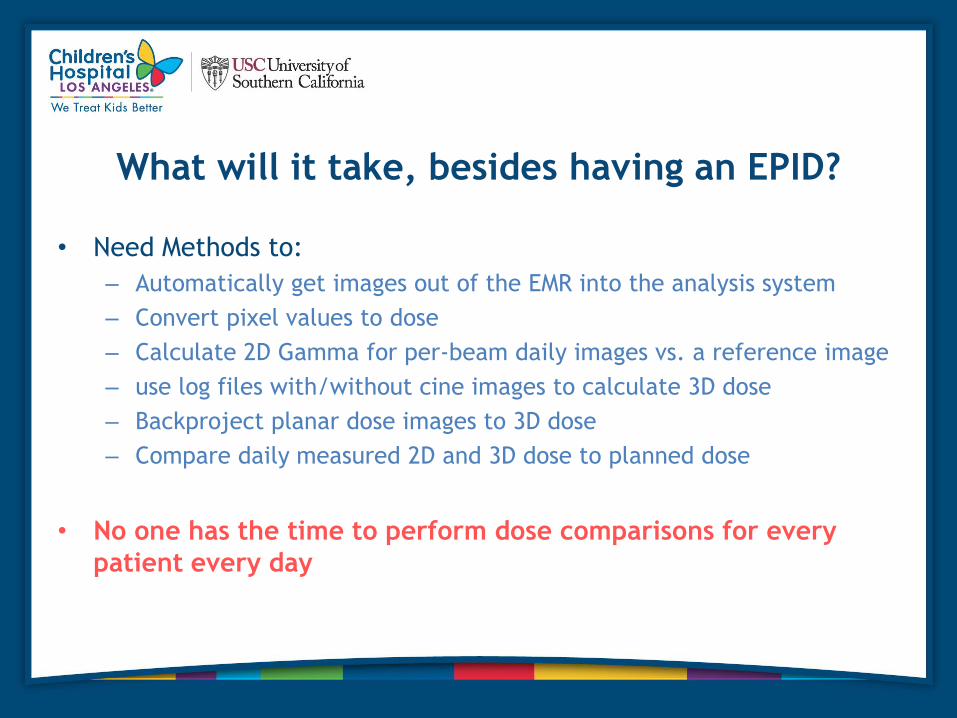
What will it take, besides having an EPID?
• Need Methods to:
– Automatically get images out of the EMR into the analysis system
– Convert pixel values to dose
– Calculate 2D Gamma for per-beam daily images vs. a reference image
– use log files with/without cine images to calculate 3D dose
– Backproject planar dose images to 3D dose
– Compare daily measured 2D and 3D dose to planned dose
• No one has the time to perform dose comparisons for every
patient every day

What has already been Done?
Studies go back 15 years !


2002
2008
2003
1996
2007

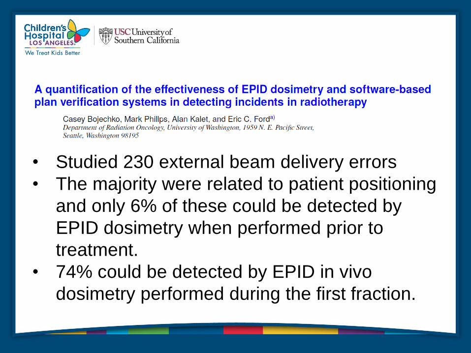
• Studied 230 external beam delivery errors
• The majority were related to patient positioning
and only 6% of these could be detected by
EPID dosimetry when performed prior to
treatment.
• 74% could be detected by EPID in vivo
dosimetry performed during the first fraction.

Pretreatment EPID QA In vivo EPID QA
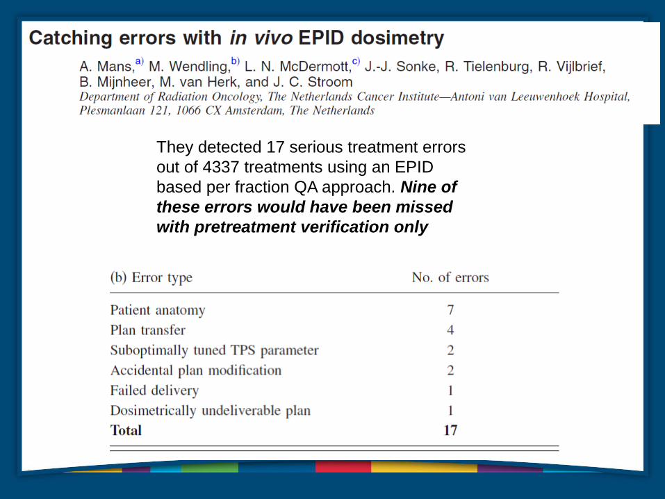
They detected 17 serious treatment errors
out of 4337 treatments using an EPID
based per fraction QA approach. Nine of
these errors would have been missed
with pretreatment verification only
15

Log File Concerns
• The accuracy of machine information recorded on the log file remains unclear.
• Is the recorded information measured with independent sensors; what is the accuracy and uncertainty of those
sensors; can we perform adequate calibration and QA as we do for ion chambers and other QA devices; and are
there failure modes for which the sensors fail to detect errors.
• Incident at a TomoTherapy site - the jaw sizes were varying during rotational delivery while the jaw position
recorded on the log file recorded the same position as planned. The jaw was driven by a stepping motor and its
connection was loose, leaving the jaw freely moving, whereas stepping motor positions recorded on the log file
were per the plan.
• It has been speculated that the MLCs in Varian linacs may potentially have the same issue, since they use similar
stepping motors for controlling MLCs.
• There are several important aspects of treatment delivery that currently are not recorded in log files, such as
beam symmetry and energy.
• Log files can’t tell you anything about the patient setup or anatomy changes
• The log file-based QA approach offers many advantages, yet it still requires further investigation of its
limitations before it is clinically adopted.

Log Files !

Log File 3D dose vs. EPID
Exit images
18
1%
higher
delivered
dose
More pixels failed low
than high
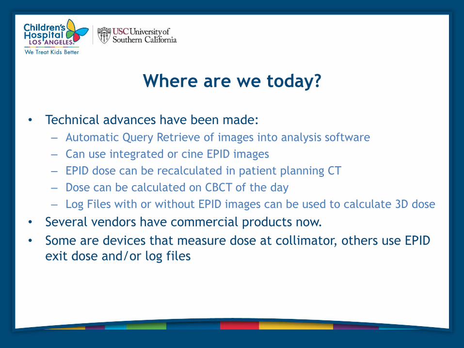
Where are we today?
• Technical advances have been made:
– Automatic Query Retrieve of images into analysis software
– Can use integrated or cine EPID images
– EPID dose can be recalculated in patient planning CT
– Dose can be calculated on CBCT of the day
– Log Files with or without EPID images can be used to calculate 3D dose
• Several vendors have commercial products now.
• Some are devices that measure dose at collimator, others use EPID
exit dose and/or log files
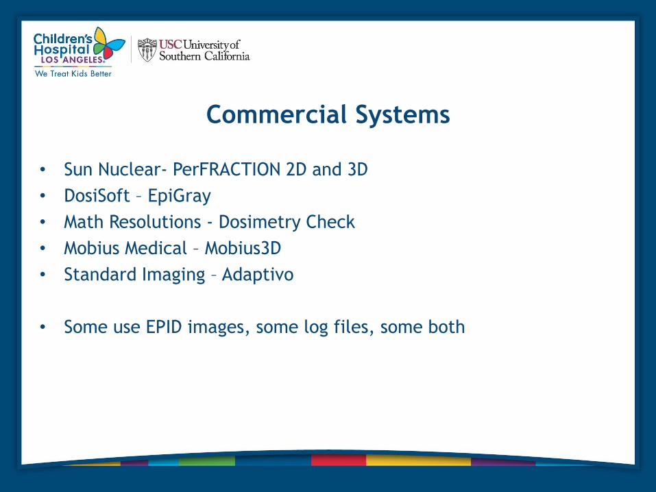
Commercial Systems
• Sun Nuclear- PerFRACTION 2D and 3D
• DosiSoft – EpiGray
• Math Resolutions - Dosimetry Check
• Mobius Medical – Mobius3D
• Standard Imaging – Adaptivo
• Some use EPID images, some log files, some both

New Paradigm
• Fully automated data capture and analysis makes daily patient
treatment QA feasible
• Uses imaging hardware we all already have
• Provides a significant enhancement in patient safety and
understanding of actual absorbed dose in the patient during the
course of treatment

What Can These Systems Do?
1. 2D Gamma Analysis using EPID images per field for fraction N vs.
fraction 1 or vs. predicted image from TPS
2. 3D dose, 3D gamma, point dose, and DVH comparison to TPS (in
planning CT or CBCT of the day) using Cine images of each field
(along with log files)
3. Pretreatment QA using EPID images of each field calculated against
the TPS dose or an independent dose calc. Log files can also be
used.
22

Vendors are Dependent on Varian and Elekta
• For Log files – Varian doesn’t yet fully support Log files
• For raw cine images- Varian doesn’t make available on TrueBeam
• For CBCT registration files – Varian doesn’t comply fully with IHE-
RO
• Aria and Mosaiq issues
• Elekta issues
23
Using the EPID as a High Resolution Absolute
Dose Detector Array for Pretreatment QA
• Is being offered by several vendors
• Although more efficient and easier than using a separate
measurement device, NOT what’s novel.
• What’s groundbreaking is the ability to detect and measure errors
in daily treatment.
24
SNC PerFRACTION
• Performs 2D gamma analysis comparison of the EPID image on the
first fraction vs. all subsequent fractions or vs. TPS predicted
image (later this year).
• Performs 3D calculation of daily dose in planning CT or CBCT and
allows DVH comparisons between daily dose and planned dose.
Uses Log Files for dose per CP and cine images for MLC positions.
• Performs pretreatment QA (in air) with DVH analysis in patient CT
• Trends results per patient or per linac

Dedicated Networked PC (Server)
• Embedded MS Win
• Dell Precision T3610
16GB
• Intel Xeon Processor E5-1607
v2 (Quad Core, 3.0 GHz, 10
MB)
• 3 GB NVIDIA Quadro K4000
• 256GB SSD
• 3TB Enterprise HDD
Software Setup • Works with Aria and Mosaic
• Setup Server on network
• Web-based interface
• Configure DICOM Listener with connection to RV Database (Aria or
Mosaic)
• Configure comparison tests
Workflow • Export plan, CT, SS, dose grid from TPS to SNC Server
• Get integrated (2D analysis) or cine (3D analysis) EPID images of
each treatment field/arc on every fraction
• Can review results in the PerFRACTION software (or just wait for
the email failure notifications), create plan and fraction reports

How Sensitive is the System for Finding Errors?
Experimental design
• A series of phantom plans were generated to test
various types of errors.
• The first fraction was delivered error-free.
• The subsequent fractions were delivered with induced
errors.
• We also verified EPID-linac constancy over the same
time frame as for the study images.
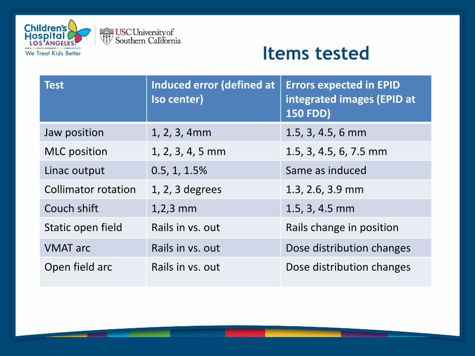
Items tested
Test Induced error (defined at Iso center)
Errors expected in EPID integrated images (EPID at 150 FDD)
Jaw position 1, 2, 3, 4mm 1.5, 3, 4.5, 6 mm
MLC position 1, 2, 3, 4, 5 mm 1.5, 3, 4.5, 6, 7.5 mm
Linac output 0.5, 1, 1.5% Same as induced
Collimator rotation 1, 2, 3 degrees 1.3, 2.6, 3.9 mm
Couch shift 1,2,3 mm 1.5, 3, 4.5 mm
Static open field Rails in vs. out Rails change in position
VMAT arc Rails in vs. out Dose distribution changes
Open field arc Rails in vs. out Dose distribution changes

Results
Test Induced error PerFRACTION detected error
EPID linac constancy None 0.20%
Jaw position 1.5 mm 1.3 mm
MLC position 1.5 mm 1.1 mm
Linac output 0.5%, 1.0%, 1.5% 0.5%, 1.2% and 1.6%
Collimator rotation 1 degree 0.7 degree
Couch shift 1.5 mm 1.7 mm
Static open field (Rail effect)
Rails in vs. out Yes, up to 8% dose change
VMAT arc (Rail effect)
Rails in vs. out
Up to 3% dose change

Conclusions
• We found that PerFRACTION is capable of detecting
sub-millimeter and sub-degree changes in field
position.
• It can detect output changes to within 0.2%.
• It is fairly sensitive at detecting whether the rails are in
or out.

My Head Immobilization System
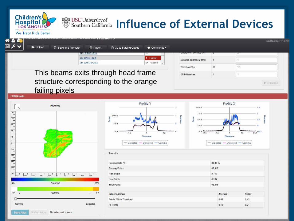
Influence of External Devices
This beams exits through head frame
structure corresponding to the orange
failing pixels

Beam Without External Device in Path

Exit Dose Change is Measured
Edge of
shoulder

Series of CBCTs showing
changing internal anatomy

Gamma results for CBCTs

Anatomy Changes Correlate
to PerFRACTION Results

Trend
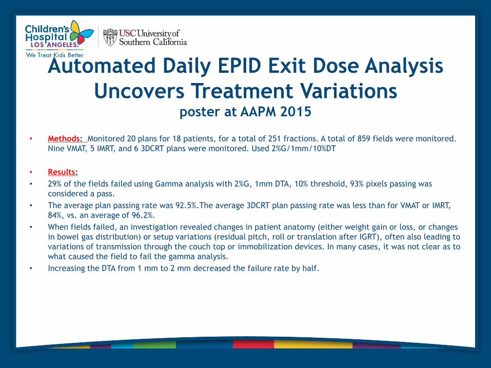
Automated Daily EPID Exit Dose Analysis
Uncovers Treatment Variations poster at AAPM 2015
• Methods: Monitored 20 plans for 18 patients, for a total of 251 fractions. A total of 859 fields were monitored.
Nine VMAT, 5 IMRT, and 6 3DCRT plans were monitored. Used 2%G/1mm/10%DT
• Results:
• 29% of the fields failed using Gamma analysis with 2%G, 1mm DTA, 10% threshold, 93% pixels passing was
considered a pass.
• The average plan passing rate was 92.5%.The average 3DCRT plan passing rate was less than for VMAT or IMRT,
84%, vs. an average of 96.2%.
• When fields failed, an investigation revealed changes in patient anatomy (either weight gain or loss, or changes
in bowel gas distribution) or setup variations (residual pitch, roll or translation after IGRT), often also leading to
variations of transmission through the couch top or immobilization devices. In many cases, it was not clear as to
what caused the field to fail the gamma analysis.
• Increasing the DTA from 1 mm to 2 mm decreased the failure rate by half.

Conclusion
• EPID exit dose systems provide daily automated 2D and 3D dose analysis using EPID integrated or cine images with or without log file usage.
• Pretreatment IMRT QA can be done with the EPID in a time saving manner.
• Therapists deploy EPID, no extra Physics effort.
• Passing rates/trends for each field and plan are provided to uncover delivery/setup errors.
• Tolerance limits to use for analysis not yet established.
• Reasons for failures are multifactorial-MLC/linac delivery problems, patient setup differences, patient internal anatomy changes.
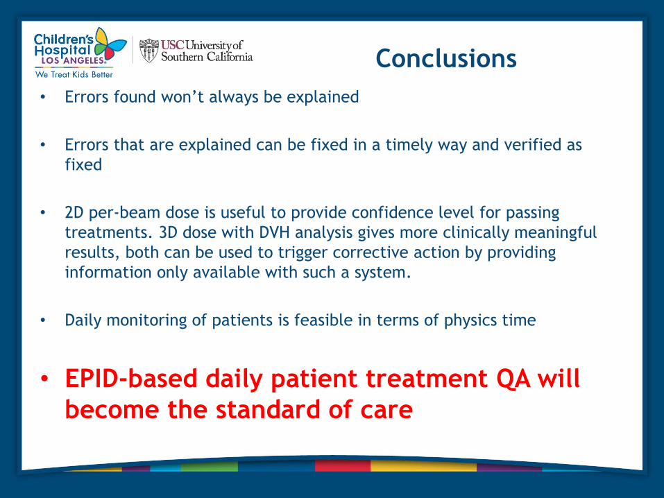
Conclusions
• Errors found won’t always be explained
• Errors that are explained can be fixed in a timely way and verified as
fixed
• 2D per-beam dose is useful to provide confidence level for passing
treatments. 3D dose with DVH analysis gives more clinically meaningful
results, both can be used to trigger corrective action by providing
information only available with such a system.
• Daily monitoring of patients is feasible in terms of physics time
• EPID-based daily patient treatment QA will
become the standard of care

The End
Questions?
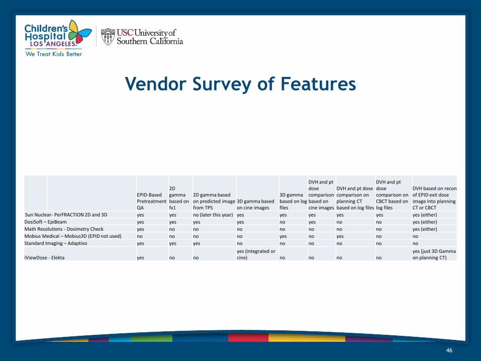
Vendor Survey of Features
46
EPID-Based Pretreatment QA
2D gamma based on fx1
2D gamma based on predicted image from TPS
3D gamma based on cine images
3D gamma based on log files
DVH and pt dose comparison based on cine images
DVH and pt dose comparison on planning CT based on log files
DVH and pt dose comparison on CBCT based on log files
DVH based on recon of EPID exit dose image into planning CT or CBCT
Sun Nuclear- PerFRACTION 2D and 3D yes yes no (later this year) yes yes yes yes yes yes (either)
DosiSoft – EpiBeam yes yes yes yes no yes no no yes (either)
Math Resolutions - Dosimetry Check yes no no no no no no no yes (either)
Mobius Medical – Mobius3D (EPID not used) no no no no yes no yes no no
Standard Imaging – Adaptivo yes yes yes no no no no no no
iViewDose - Elekta yes no no yes (integrated or cine) no no no no
yes (just 3D Gamma on planning CT)

References
47