entrypass platform1 server & hcb configuration guide server and hcb... · ‘192.168.1.100’...
TRANSCRIPT

Copyright © Entrypass Corporation
ENTRYPASS TECHNICAL – CONFIGURATION GUIDE
ENTRYPASS PLATFORM1 SERVER & HCB
CONFIGURATION GUIDE
Version: 1.01
Last Updated: 22-07-2016
1
Copyright © Entrypass Corporation
ENTRYPASS TECHNICAL – CONFIGURATION GUIDE
Technical Support If you cannot find the answer to your question in this manual or in the Help files, we recommend you contact your system installer. Your installer is familiar with your system configuration and should be able to answer any of your questions.
Should you need additional information, please call our Technical Support Help desk, Monday to Friday 9:00 AM to 6:00 PM (GMT +8:00) Method Details Phone + 60 (3) - 8068 1929 Fax + 60 (3) - 8068 1922
Internet www.entrypass.net Email [email protected]
BEFORE YOU BEGIN
2
Copyright © Entrypass Corporation
ENTRYPASS TECHNICAL – CONFIGURATION GUIDE
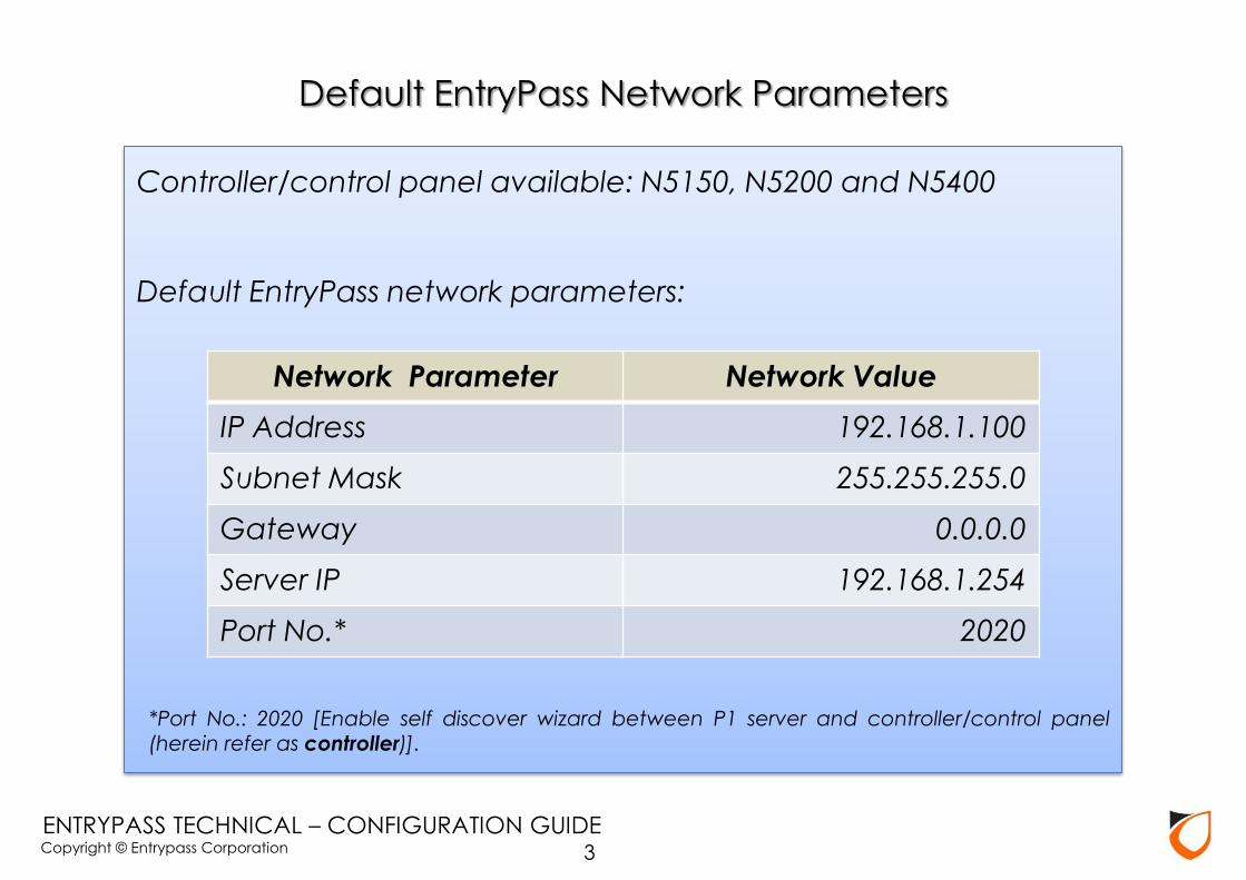
Controller/control panel available: N5150, N5200 and N5400
Default EntryPass network parameters:
*Port No.: 2020 [Enable self discover wizard between P1 server and controller/control panel (herein refer as controller)].
Default EntryPass Network Parameters
Network Parameter Network Value
IP Address 192.168.1.100
Subnet Mask 255.255.255.0
Gateway 0.0.0.0
Server IP 192.168.1.254
Port No.* 2020
3
Copyright © Entrypass Corporation
ENTRYPASS TECHNICAL – CONFIGURATION GUIDE
EP Device Server Manager
(Web Server Configuration)
4
Copyright © Entrypass Corporation
ENTRYPASS TECHNICAL – CONFIGURATION GUIDE 5
Before Start…
HCB based (N5150, N5200, N5400) and HIO Network
controller come with web-base Device Server Manager.
User can easily view the controller information of the
controller as well as do some basic configuration such as
Network Setting. Every EntryPass network controller were
configured to default IP address (192.168.1.100). So user
can login to web-base Device Server Manager via this
default IP Address using compatible internet browser.

Copyright © Entrypass Corporation
ENTRYPASS TECHNICAL – CONFIGURATION GUIDE
Supported Browser: 1. Internet Explorer* 2. Mozilla Firefox* 3. Google Chrome
4. Opera 5. Apple Safari
* Can Perform Firmware Upgrade
6

Copyright © Entrypass Corporation
ENTRYPASS TECHNICAL – CONFIGURATION GUIDE
Notes: Please refer to ‘EP Device Manager User Guide’ for more information on how to configure network parameter.
7
1. Enter default controller IP ‘192.168.1.100’ and then hit
button
2. Enter ‘123456’ for password
3. Click ‘Login’ button to enter ‘Device Server Manager’

Copyright © Entrypass Corporation
ENTRYPASS TECHNICAL – CONFIGURATION GUIDE 8
Click ‘Network’ option

Copyright © Entrypass Corporation
ENTRYPASS TECHNICAL – CONFIGURATION GUIDE
Web Server Interface
There are 2 types of Web Server Interface. Each Web Server
Interface contents would have different layout of user
interface design depending on the controller firmware
version as below:
(a) Firmware version V4.13 or below
(b) Firmware version V4.14 or above
9
Copyright © Entrypass Corporation
ENTRYPASS TECHNICAL – CONFIGURATION GUIDE
Firmware version 4.13 or below
10
Copyright © Entrypass Corporation
ENTRYPASS TECHNICAL – CONFIGURATION GUIDE
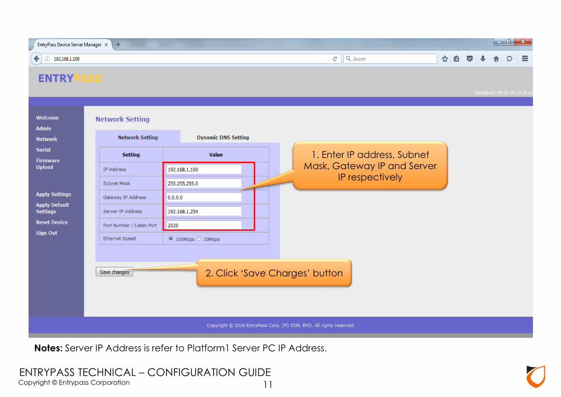
Notes: Server IP Address is refer to Platform1 Server PC IP Address.
1. Enter IP address, Subnet Mask, Gateway IP and Server
IP respectively
2. Click ‘Save Charges’ button
11

Copyright © Entrypass Corporation
ENTRYPASS TECHNICAL – CONFIGURATION GUIDE
Click ‘Apply Settings’ button to apply setting to controller
12
Copyright © Entrypass Corporation
ENTRYPASS TECHNICAL – CONFIGURATION GUIDE 13
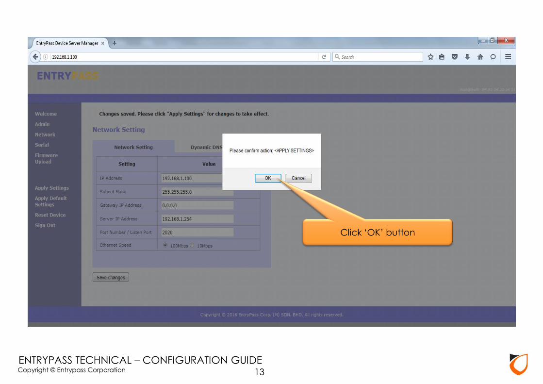
Click ‘OK’ button
Copyright © Entrypass Corporation
ENTRYPASS TECHNICAL – CONFIGURATION GUIDE 14
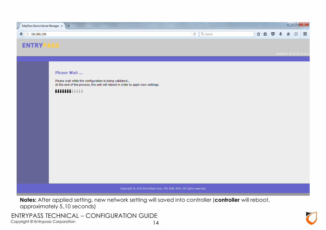
Notes: After applied setting, new network setting will saved into controller (controller will reboot, approximately 5~10 seconds)
Copyright © Entrypass Corporation
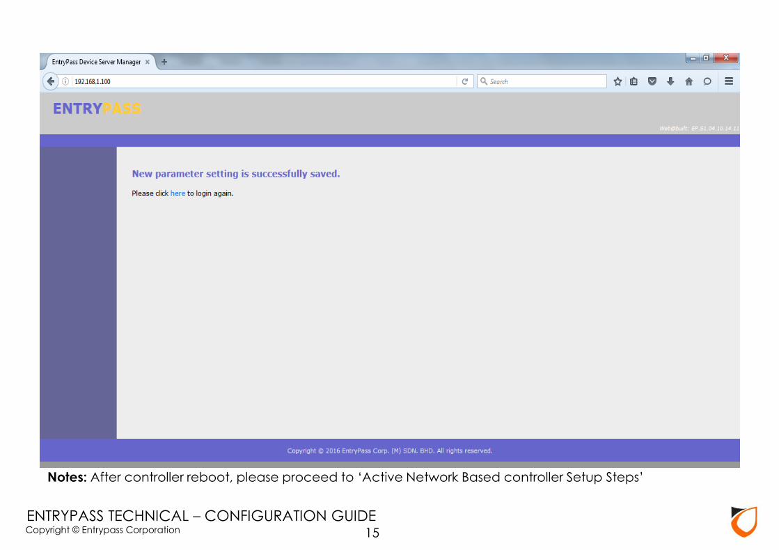
ENTRYPASS TECHNICAL – CONFIGURATION GUIDE 15
Notes: After controller reboot, please proceed to ‘Active Network Based controller Setup Steps’

Copyright © Entrypass Corporation
ENTRYPASS TECHNICAL – CONFIGURATION GUIDE
Firmware version 4.14 or below
16

Copyright © Entrypass Corporation
ENTRYPASS TECHNICAL – CONFIGURATION GUIDE
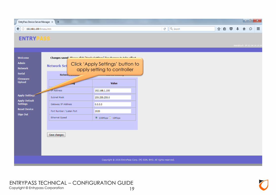
Enter IP address, Subnet Mask, and Gateway IP respectively
17

Copyright © Entrypass Corporation
ENTRYPASS TECHNICAL – CONFIGURATION GUIDE
1. Enter Server IP
2. Click ‘Save Charges’ button
18
Copyright © Entrypass Corporation
ENTRYPASS TECHNICAL – CONFIGURATION GUIDE
Click ‘Apply Settings’ button to
apply setting to controller
19

Copyright © Entrypass Corporation
ENTRYPASS TECHNICAL – CONFIGURATION GUIDE
Click ‘OK’ button
20

Copyright © Entrypass Corporation
ENTRYPASS TECHNICAL – CONFIGURATION GUIDE
Notes: After applied setting, new network setting will saved into controller (controller will reboot, approximately 5~10 seconds)
21

Copyright © Entrypass Corporation
ENTRYPASS TECHNICAL – CONFIGURATION GUIDE
Notes: After controller reboot, please proceed to ‘Active Network Controller Setup Steps’
22
Copyright © Entrypass Corporation
ENTRYPASS TECHNICAL – CONFIGURATION GUIDE 23
Active Network Controller Setup
Steps

Copyright © Entrypass Corporation
ENTRYPASS TECHNICAL – CONFIGURATION GUIDE
Notes: If the controller network parameter configured correctly, the ‘New Controller Found’ wizard will auto pop up on the screen.
24

Copyright © Entrypass Corporation
ENTRYPASS TECHNICAL – CONFIGURATION GUIDE
Click ‘Configure Later’ button
25
Copyright © Entrypass Corporation
ENTRYPASS TECHNICAL – CONFIGURATION GUIDE
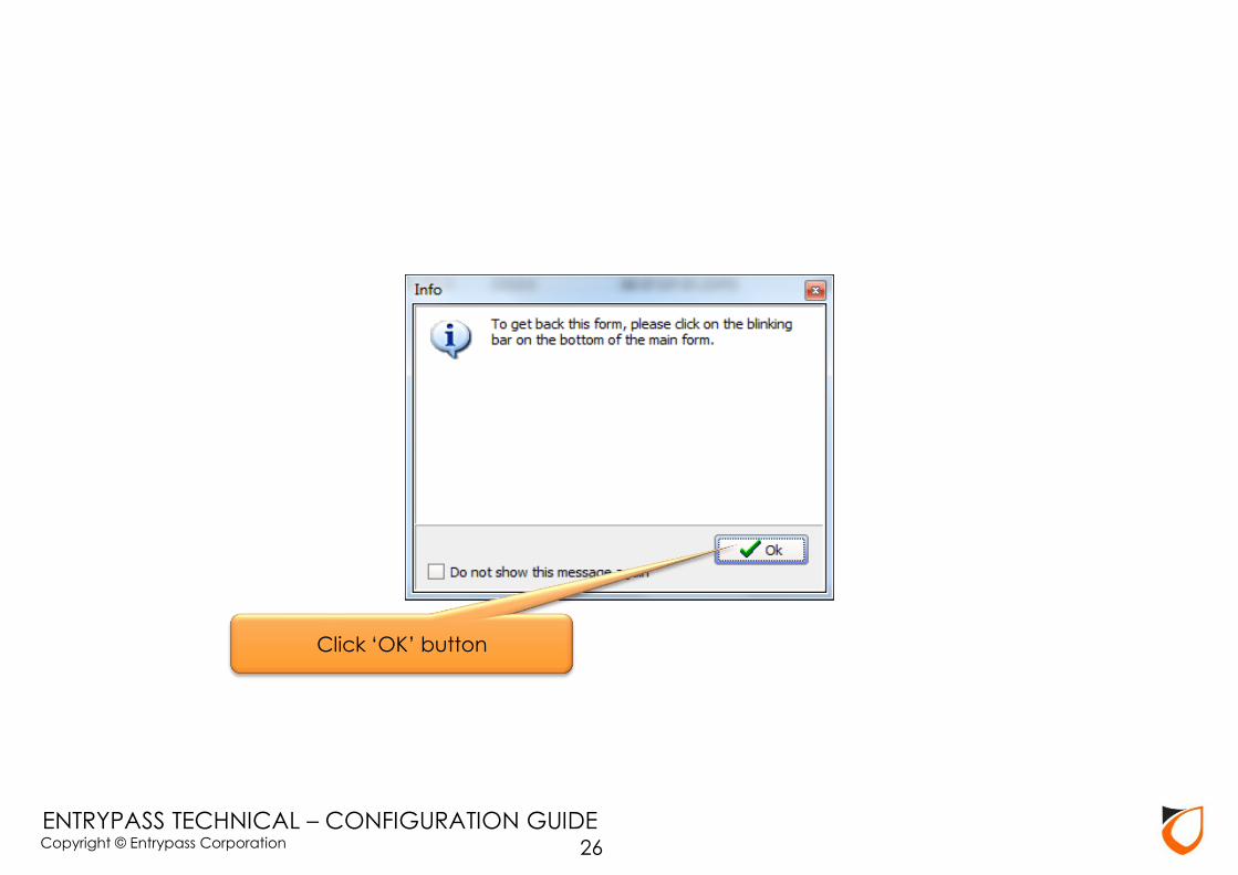
Click ‘OK’ button
26

Copyright © Entrypass Corporation
ENTRYPASS TECHNICAL – CONFIGURATION GUIDE
2. Click ‘Preferences’ icon
1. Click ‘Control Panel’ tab
27

Copyright © Entrypass Corporation
ENTRYPASS TECHNICAL – CONFIGURATION GUIDE
Default: Login name : EntryPass Password : EntryPass
28
Copyright © Entrypass Corporation
ENTRYPASS TECHNICAL – CONFIGURATION GUIDE
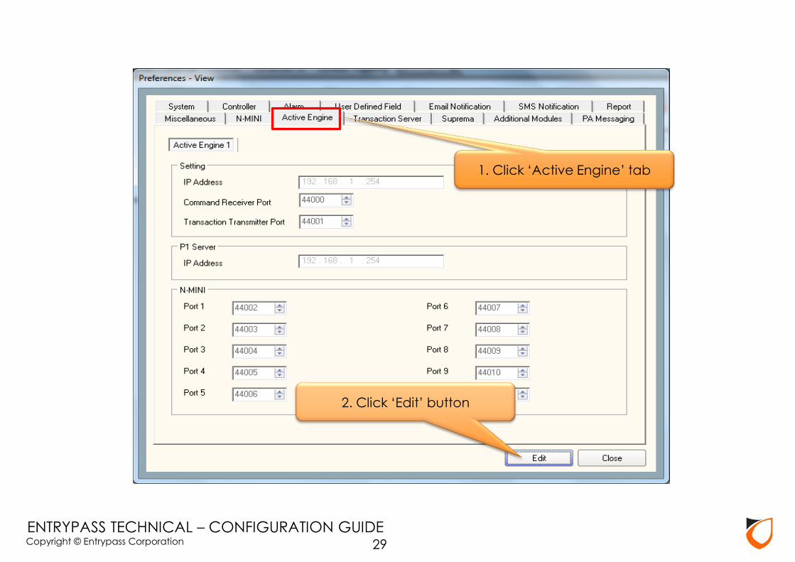
1. Click ‘Active Engine’ tab
2. Click ‘Edit’ button
29

Copyright © Entrypass Corporation
ENTRYPASS TECHNICAL – CONFIGURATION GUIDE
3. Click ‘Accept’ button
1. Ensure ‘Active Engine’ IP address is correct
2. Ensure ‘P1 Server’ IP address is correct
30

Copyright © Entrypass Corporation
ENTRYPASS TECHNICAL – CONFIGURATION GUIDE
Click ‘Close’ button
31
Copyright © Entrypass Corporation
ENTRYPASS TECHNICAL – CONFIGURATION GUIDE
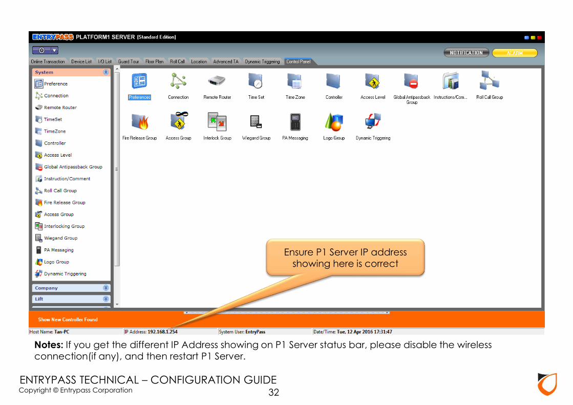
Notes: If you get the different IP Address showing on P1 Server status bar, please disable the wireless connection(if any), and then restart P1 Server.
Ensure P1 Server IP address showing here is correct
32
Copyright © Entrypass Corporation
ENTRYPASS TECHNICAL – CONFIGURATION GUIDE
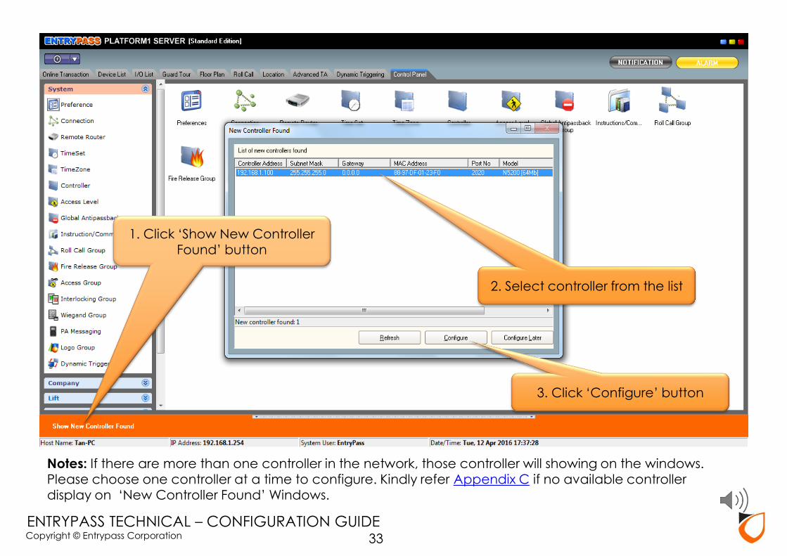
Notes: If there are more than one controller in the network, those controller will showing on the windows. Please choose one controller at a time to configure. Kindly refer Appendix C if no available controller display on ‘New Controller Found’ Windows.
1. Click ‘Show New Controller Found’ button
2. Select controller from the list
3. Click ‘Configure’ button
33

Copyright © Entrypass Corporation
ENTRYPASS TECHNICAL – CONFIGURATION GUIDE
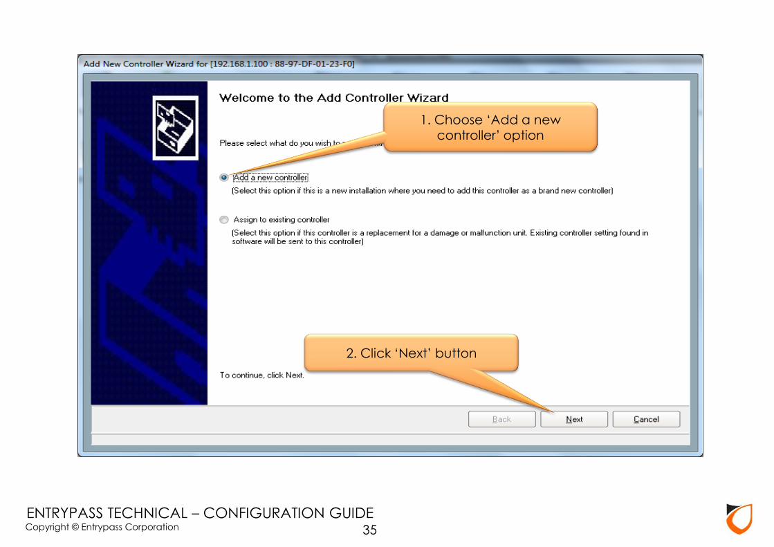
Notes: For new installation, please select ‘Add new controller’ option. For replacement installation, please select ‘Assign to existing controller’ option.
34
Copyright © Entrypass Corporation
ENTRYPASS TECHNICAL – CONFIGURATION GUIDE
2. Click ‘Next’ button
1. Choose ‘Add a new controller’ option
35
Copyright © Entrypass Corporation
ENTRYPASS TECHNICAL – CONFIGURATION GUIDE
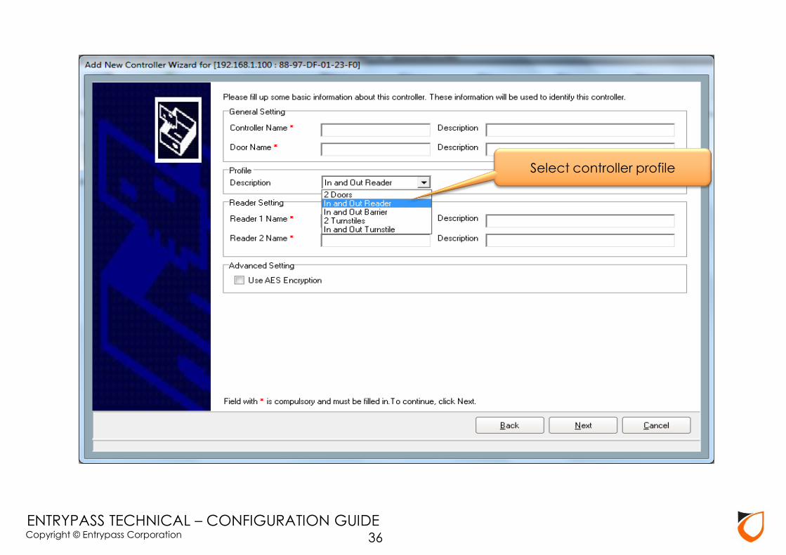
Select controller profile
36

Copyright © Entrypass Corporation
ENTRYPASS TECHNICAL – CONFIGURATION GUIDE
3. Click ‘Next’ button
1. Enter controller name, door name and description
2. Enter reader name and description
37
Copyright © Entrypass Corporation
ENTRYPASS TECHNICAL – CONFIGURATION GUIDE
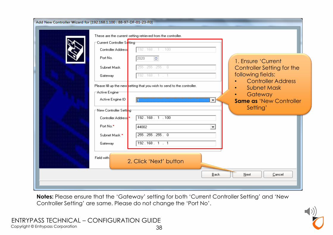
Notes: Please ensure that the ‘Gateway’ setting for both ‘Current Controller Setting’ and ‘New Controller Setting’ are same. Please do not change the ‘Port No’.
1. Ensure ‘Current Controller Setting for the following fields: • Controller Address • Subnet Mask
• Gateway Same as ‘New Controller
Setting’
2. Click ‘Next’ button
38
Copyright © Entrypass Corporation
ENTRYPASS TECHNICAL – CONFIGURATION GUIDE
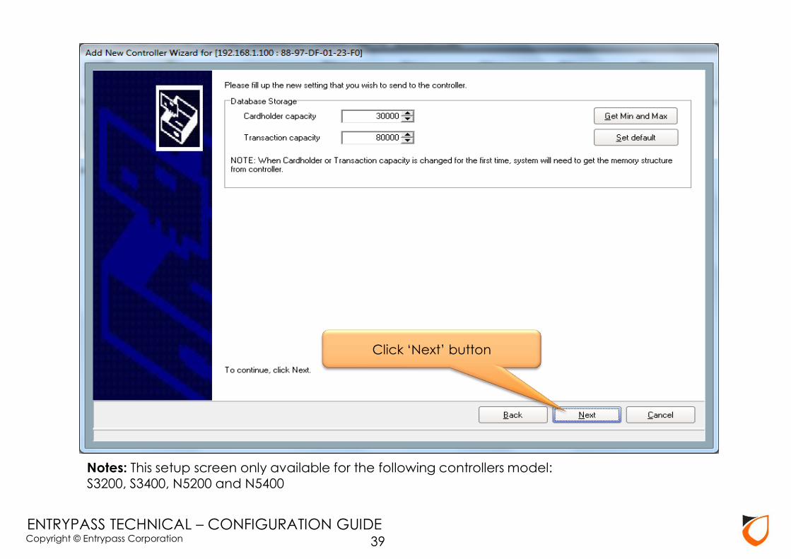
Notes: This setup screen only available for the following controllers model: S3200, S3400, N5200 and N5400
Click ‘Next’ button
39

Copyright © Entrypass Corporation
ENTRYPASS TECHNICAL – CONFIGURATION GUIDE
Click ‘Finish’ button
40
Copyright © Entrypass Corporation
ENTRYPASS TECHNICAL – CONFIGURATION GUIDE
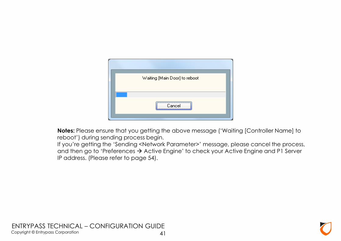
Notes: Please ensure that you getting the above message (‘Waiting [Controller Name] to reboot’) during sending process begin.
If you’re getting the ‘Sending <Network Parameter>’ message, please cancel the process, and then go to ‘Preferences Active Engine’ to check your Active Engine and P1 Server IP address. (Please refer to page 54).
41

Copyright © Entrypass Corporation
ENTRYPASS TECHNICAL – CONFIGURATION GUIDE
Notes: Please go to ‘Device List’ to check the controller status. Kindly refer Appendix C if the controller status is down.
Click ‘Device List’ tab
42
Copyright © Entrypass Corporation
ENTRYPASS TECHNICAL – CONFIGURATION GUIDE
Serial (RS232/RS485) Controller
Setup Steps
43
Copyright © Entrypass Corporation
ENTRYPASS TECHNICAL – CONFIGURATION GUIDE
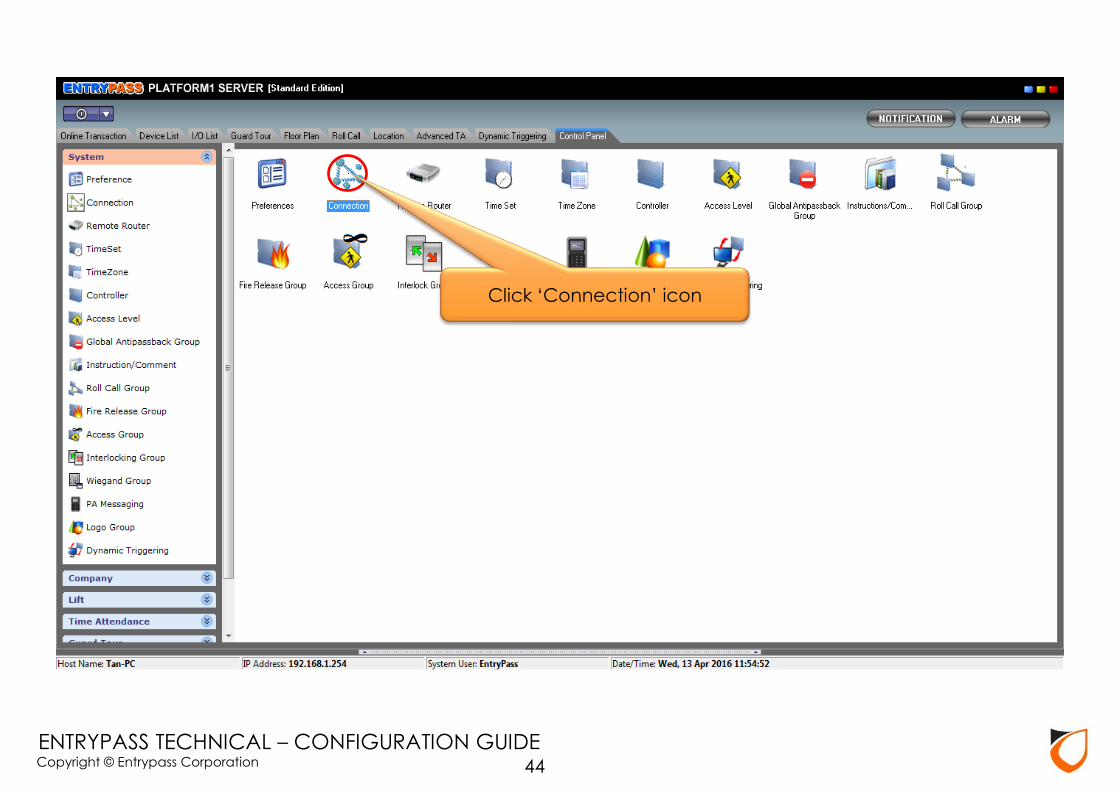
Click ‘Connection’ icon
44
Copyright © Entrypass Corporation
ENTRYPASS TECHNICAL – CONFIGURATION GUIDE
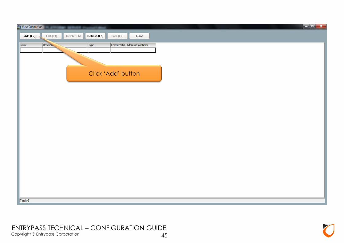
Click ‘Add’ button
45
Copyright © Entrypass Corporation
ENTRYPASS TECHNICAL – CONFIGURATION GUIDE
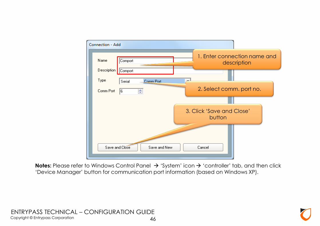
Notes: Please refer to Windows Control Panel ‘System’ icon ‘controller’ tab, and then click
‘Device Manager’ button for communication port information (based on Windows XP).
2. Select comm. port no.
1. Enter connection name and description
3. Click ‘Save and Close’ button
46
Copyright © Entrypass Corporation
ENTRYPASS TECHNICAL – CONFIGURATION GUIDE
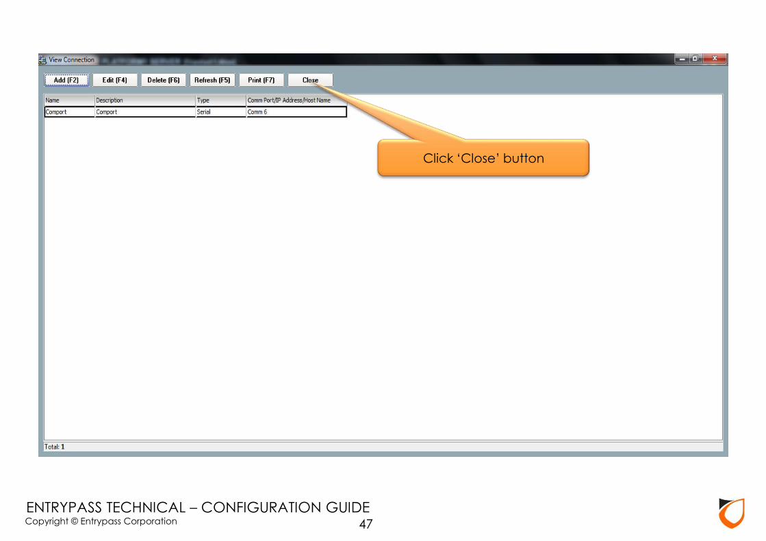
Click ‘Close’ button
47
Copyright © Entrypass Corporation
ENTRYPASS TECHNICAL – CONFIGURATION GUIDE
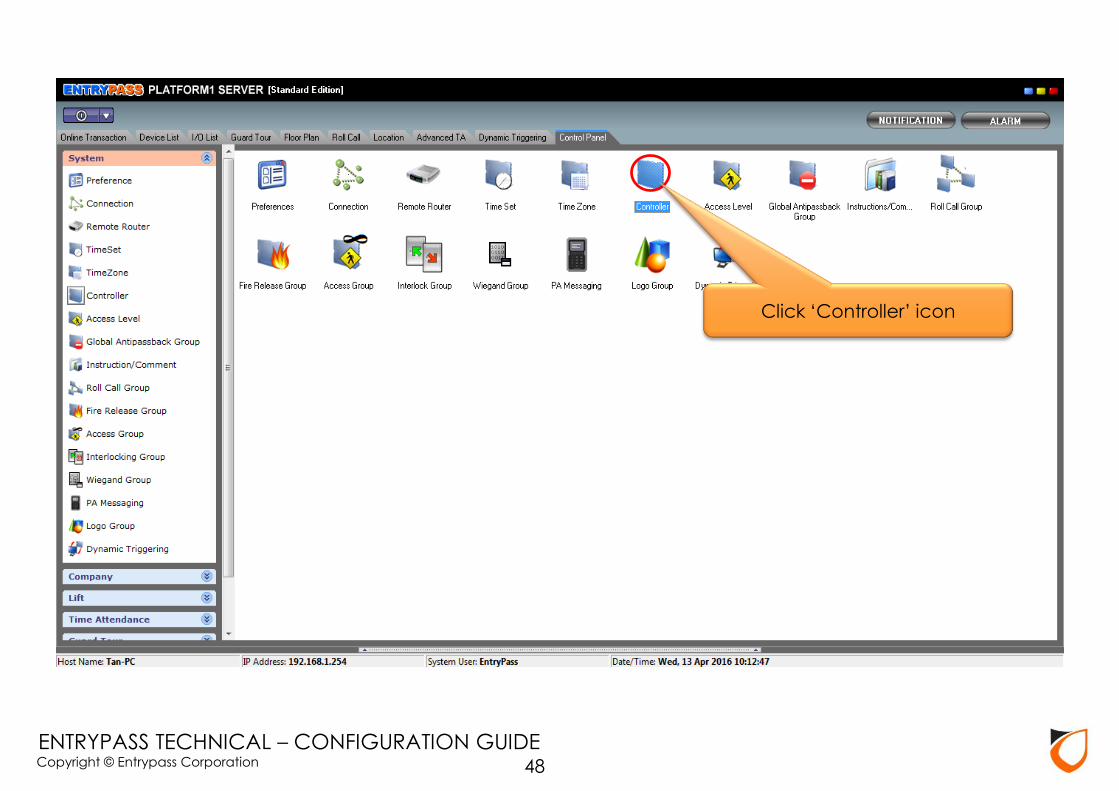
Click ‘Controller’ icon
48
Copyright © Entrypass Corporation
ENTRYPASS TECHNICAL – CONFIGURATION GUIDE
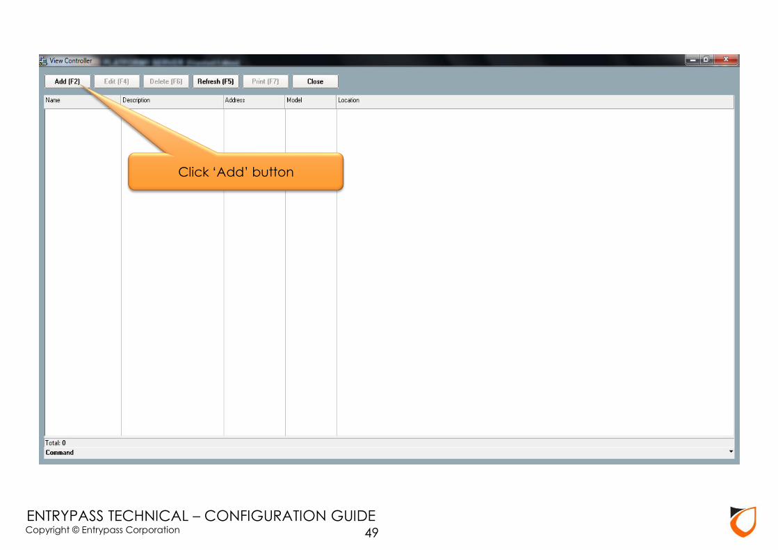
Click ‘Add’ button
49
Copyright © Entrypass Corporation
ENTRYPASS TECHNICAL – CONFIGURATION GUIDE
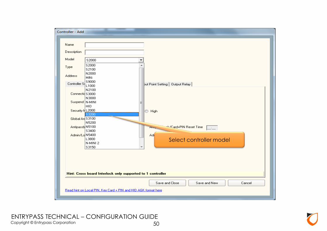
Select controller model
50

Copyright © Entrypass Corporation
ENTRYPASS TECHNICAL – CONFIGURATION GUIDE
Notes: Unit address for HCB Serial Board is starting with 3 octets of 255, the last octets represents the dip-switch selected on the controller controller (kindly refer Appendix B for Dip-Switch Addressing
Table)
51
2. Enter controller unit address
1. Enter controller name and description
3. Click ‘Undefined’ option

Copyright © Entrypass Corporation
ENTRYPASS TECHNICAL – CONFIGURATION GUIDE 52
1. Select connection
2. Click ‘Select’ button

Copyright © Entrypass Corporation
ENTRYPASS TECHNICAL – CONFIGURATION GUIDE
Notes: After selected the connection, the connection name will showing on the
connection field.
53
Click ‘Load Profile’ button

Copyright © Entrypass Corporation
ENTRYPASS TECHNICAL – CONFIGURATION GUIDE 54
Select controller profile

Copyright © Entrypass Corporation
ENTRYPASS TECHNICAL – CONFIGURATION GUIDE 55
1. Click ‘Door Setting’ tab
2. Enter door name and description
Copyright © Entrypass Corporation
ENTRYPASS TECHNICAL – CONFIGURATION GUIDE 56
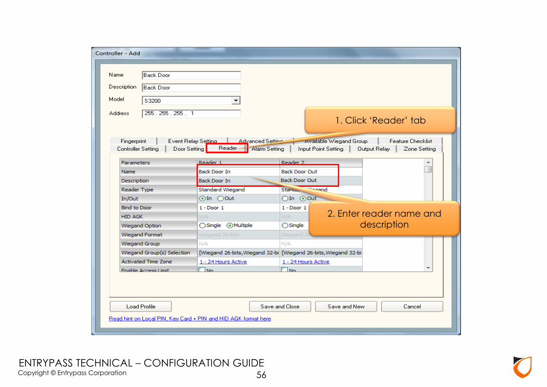
1. Click ‘Reader’ tab
2. Enter reader name and description
Copyright © Entrypass Corporation
ENTRYPASS TECHNICAL – CONFIGURATION GUIDE
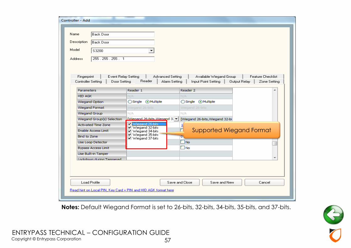
Notes: Default Wiegand Format is set to 26-bits, 32-bits, 34-bits, 35-bits, and 37-bits.
57
Supported Wiegand Format
Copyright © Entrypass Corporation
ENTRYPASS TECHNICAL – CONFIGURATION GUIDE
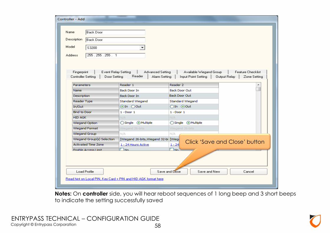
Notes: On controller side, you will hear reboot sequences of 1 long beep and 3 short beeps to indicate the setting successfully saved
58
Click ‘Save and Close’ button

Copyright © Entrypass Corporation
ENTRYPASS TECHNICAL – CONFIGURATION GUIDE 59
Click ‘Close’ button

Copyright © Entrypass Corporation
ENTRYPASS TECHNICAL – CONFIGURATION GUIDE
Notes: Please go to ‘Device List’ to check the controller status. Kindly refer Appendix C if the controller status is down.
60
Click ‘Device List’ tab

Copyright © Entrypass Corporation
ENTRYPASS TECHNICAL – CONFIGURATION GUIDE
APPENDIX
61

Copyright © Entrypass Corporation
ENTRYPASS TECHNICAL – CONFIGURATION GUIDE
Appendix A: Network Cable Connection
62
Copyright © Entrypass Corporation
ENTRYPASS TECHNICAL – CONFIGURATION GUIDE
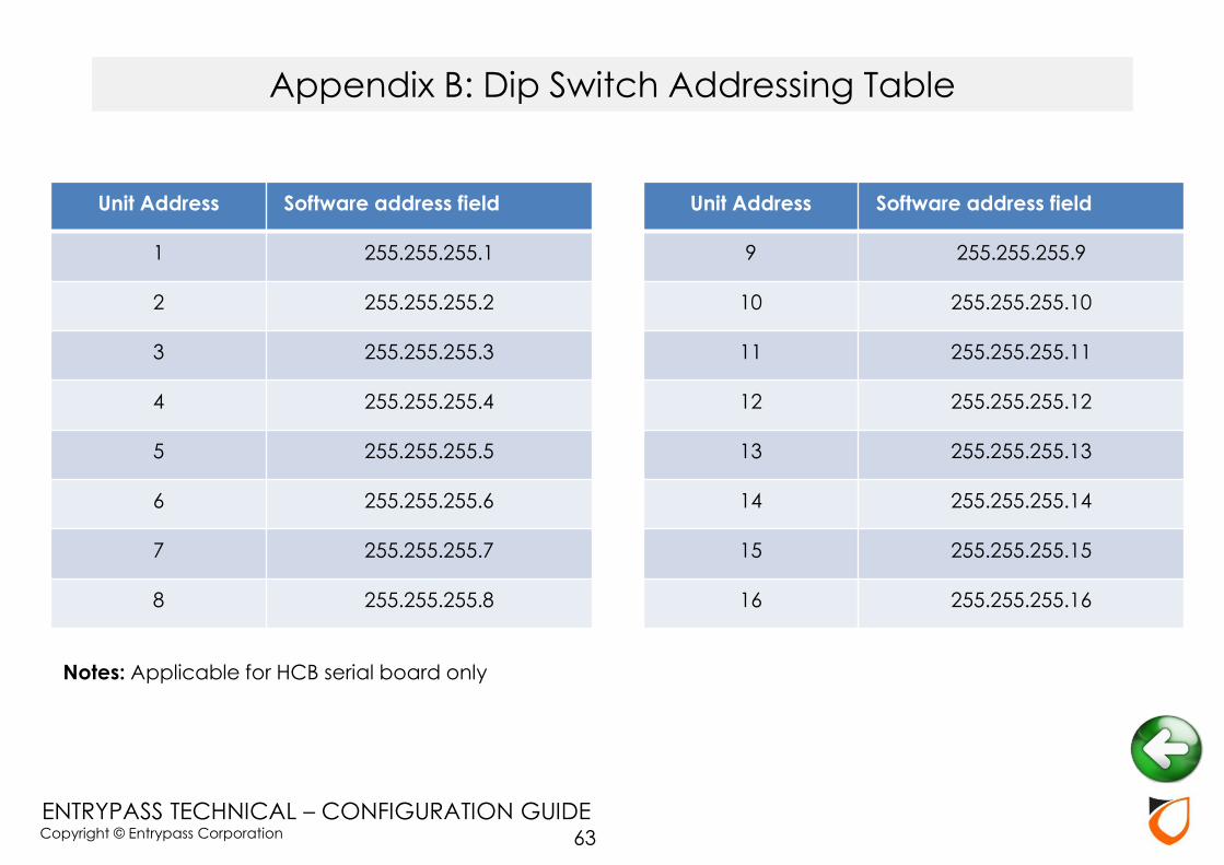
Unit Address Software address field
1 255.255.255.1
2 255.255.255.2
3 255.255.255.3
4 255.255.255.4
5 255.255.255.5
6 255.255.255.6
7 255.255.255.7
8 255.255.255.8
Unit Address Software address field
9 255.255.255.9
10 255.255.255.10
11 255.255.255.11
12 255.255.255.12
13 255.255.255.13
14 255.255.255.14
15 255.255.255.15
16 255.255.255.16
Notes: Applicable for HCB serial board only
Appendix B: Dip Switch Addressing Table
63
Copyright © Entrypass Corporation
ENTRYPASS TECHNICAL – CONFIGURATION GUIDE
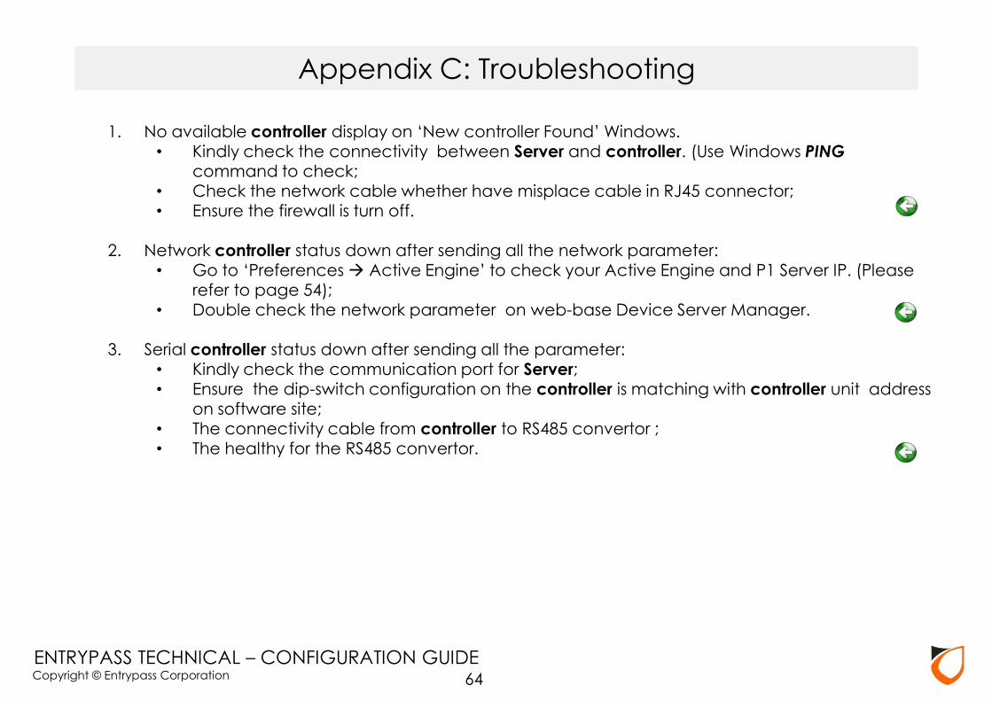
1. No available controller display on ‘New controller Found’ Windows. • Kindly check the connectivity between Server and controller. (Use Windows PING
command to check; • Check the network cable whether have misplace cable in RJ45 connector; • Ensure the firewall is turn off.
2. Network controller status down after sending all the network parameter:
• Go to ‘Preferences Active Engine’ to check your Active Engine and P1 Server IP. (Please refer to page 54);
• Double check the network parameter on web-base Device Server Manager. 3. Serial controller status down after sending all the parameter:
• Kindly check the communication port for Server; • Ensure the dip-switch configuration on the controller is matching with controller unit address
on software site; • The connectivity cable from controller to RS485 convertor ; • The healthy for the RS485 convertor.
Appendix C: Troubleshooting
64

Copyright © Entrypass Corporation
ENTRYPASS TECHNICAL – CONFIGURATION GUIDE
Appendix D: Wiegand Group Selection
65

Copyright © Entrypass Corporation
ENTRYPASS TECHNICAL – CONFIGURATION GUIDE
Step 1. Load Profile: In and Out Barrier
Appendix E: Car Park Barrier Setting
66
1. Click ‘Load Profile’ button
2. Select controller profile

Copyright © Entrypass Corporation
ENTRYPASS TECHNICAL – CONFIGURATION GUIDE
Step 2. Lock release time: 2 seconds
Appendix E: Car Park Barrier Setting
67
Set to 2 second

Copyright © Entrypass Corporation
ENTRYPASS TECHNICAL – CONFIGURATION GUIDE
Step 1. Preference Suprema Reader Type
Notes: To change ‘Reader Type’, card database must be empty
Appendix F: Suprema Setting
68
Copyright © Entrypass Corporation
ENTRYPASS TECHNICAL – CONFIGURATION GUIDE
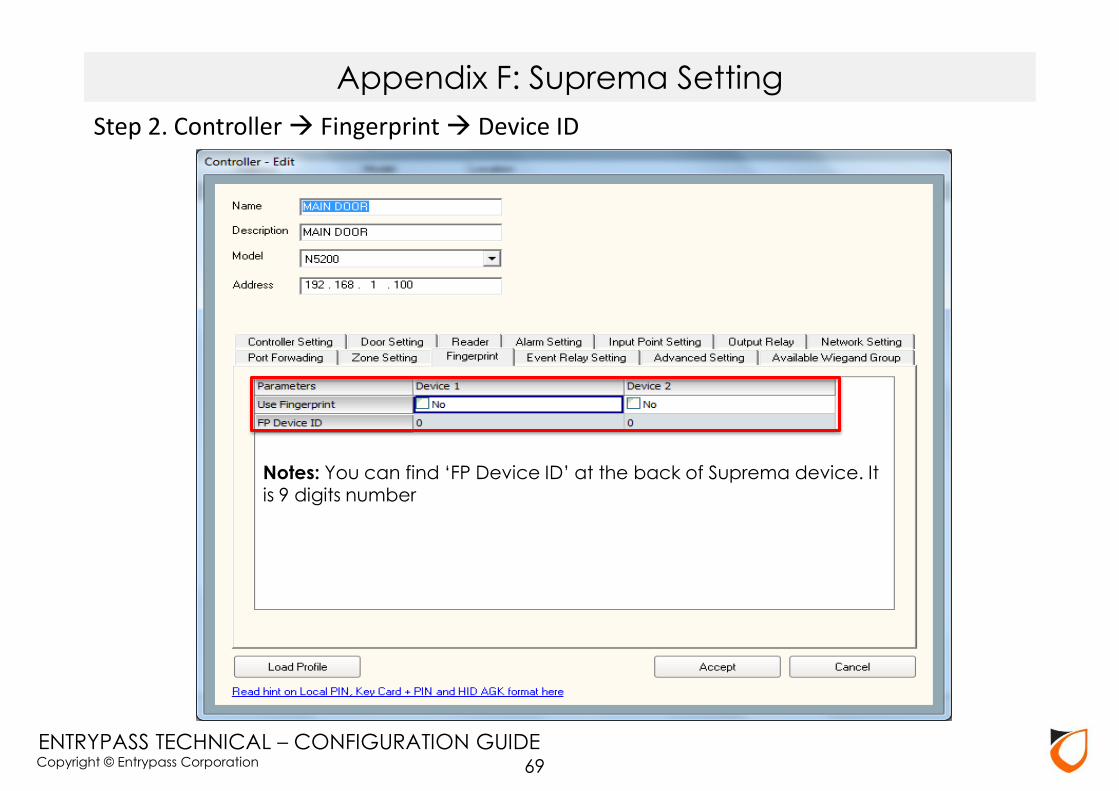
Step 2. Controller Fingerprint Device ID
Notes: You can find ‘FP Device ID’ at the back of Suprema device. It is 9 digits number
Appendix F: Suprema Setting
69

Copyright © Entrypass Corporation
ENTRYPASS TECHNICAL – CONFIGURATION GUIDE
Step 3. Controller Reader Reader Type: Suprema
Appendix F: Suprema Setting
70

Copyright © Entrypass Corporation
ENTRYPASS TECHNICAL – CONFIGURATION GUIDE
Notes: Please enter card number under ‘Card Data’ even you’re
using ‘Fingerprint’ only
Appendix G: Enroll Fingerprint
71
1. Select template ’01’
2. Click ‘Enroll’ button

Copyright © Entrypass Corporation
ENTRYPASS TECHNICAL – CONFIGURATION GUIDE
Notes: Please choose Wiegand 26 bits for Proximity format & Wiegand 32 bits for Mifare format
Appendix H: L3800 Controller Wiegand Format Setting
72
Copyright © Entrypass Corporation
ENTRYPASS TECHNICAL – CONFIGURATION GUIDE
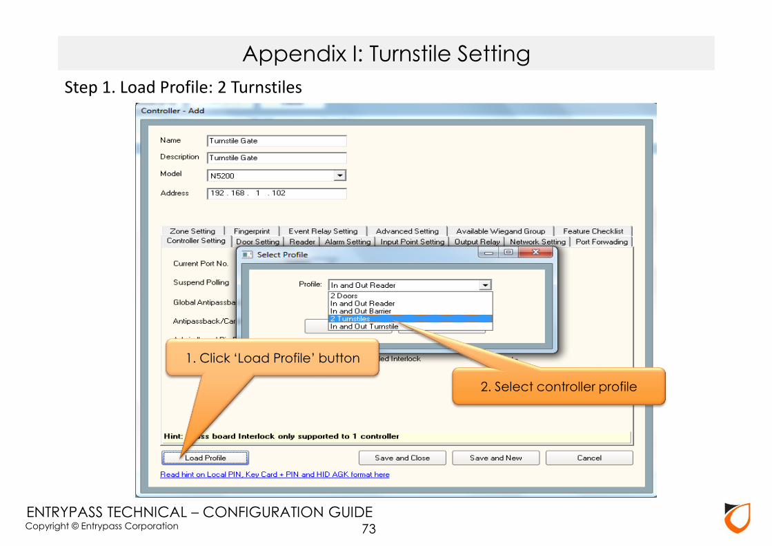
Appendix I: Turnstile Setting
Step 1. Load Profile: 2 Turnstiles
73
1. Click ‘Load Profile’ button
2. Select controller profile

Copyright © Entrypass Corporation
ENTRYPASS TECHNICAL – CONFIGURATION GUIDE
Step 2. Lock release time: 2 seconds
Appendix I: Turnstile Setting
74
Set to 2 second

Copyright © Entrypass Corporation
ENTRYPASS TECHNICAL – CONFIGURATION GUIDE
THANK YOU
75