english translation of german original - kaco new...
TRANSCRIPT

Operating Instructions
n English translation of German original
Powador-gridsaveBattery system
Operating instructions Powador-gridsave_EN Page 3
Operating Instructions
Contents
1 General Information 4
11 About this document 4
12 Name plate 5
13 Additional information 5
14 Intended use 5
2 Safety 6
21 Protection features 6
3 Description 7
31 Mode of Operation 7
32 Summary of the components 9
4 Technical Data 11
41 Electrical data 11
42 Mechanical data 12
5 Transportation and Delivery 14
51 Delivery 14
52 Storage 15
53 Transportation 15
6 Assembling the device 16
61 Installation 16
62 Installing components 17
7 Installing the device 19
71 Opening the connection area 19
72 Making the electrical connection 20
73 Connecting the interfaces25
74 Sealing the connection area 25
75 Starting up 26
76 Standard configuration 26
8 Configuration and Operation 28
81 Controls 28
9 MaintenanceTroubleshooting 32
91 Visual inspection32
92 Cleaning the device 32
93 Maintenance 33
94 Faults 33
10 Service 34
11 ShutdownDisassembly 35
111 Switching off the device 35
112 Uninstalling the device 36
113 Disassembling the device 36
12 Disposal 36
13 Appendix 37
General Information
Page 4 Operating instructions Powador-gridsave_EN
1 General Information
11 About this document
WARNINGImproper handling of the Powador-gridsave battery system can be hazardous rsaquo You must read and understand the operating instructions so that you can install and use the
device safely
111 Other applicable documents
During installation observe all assembly and installation instructions for components and other parts of the system These instructions also apply to the equipment related components and other parts of the system
112 Retention of documents
These instructions and other documents must be stored near the system and be available at all times
113 Safety warnings symbols guide information
DANGERHigh risk Failure to observe this warning will lead directly to serious bodily injury or death
WARNINGPotential riskFailure to observe this warning may lead to serious bodily injury or death
CAUTIONLow-risk hazardFailure to observe this warning will lead to minor or moderate bodily injury
CAUTIONRisk of damage to propertyFailure to observe this warning will lead to property damage
NOTEUseful information and notes
Authorised electrician The tasks indicated with this symbol may only be carried out by an authorised electrician
114 Symbols used
General hazard Risk of fire or explosion
High voltage Risk of burns
General Information
Operating instructions Powador-gridsave_EN Page 5
115 Instructions symbols guide
Instructions Prerequisite for the step
1 Carry out step
2 (Additional steps if applicable)
raquo Results of the step
12 Name plate The name plate is located on the inside of the cabinet door
13 Additional information
NOTEThe battery system uses lithium-based batteriesPlease check whether your insurance includes conditions for installation and operation of lithium batteries The retro-fitting of fire or smoke alarms may be necessary
NOTEThe EU Declaration of Conformity can be found in the appendixFor information on grid coupling grid protection and safety parameters along with more detailed instructions go to our web site httpkaco-newenergycomde
14 Intended useThe device is built according to the latest technological standards and safety regulations Nevertheless improper use may cause lethal hazards for the operator or third parties or may result in damage to the device and other property Operate the device only with a permanent connection to the public power grid Any other or additional use of the device is deemed improper This includes bull Mobile usebull Use in potentially explosive atmospheresbull Use in rooms where the humidity is higher than 95bull Operation outside of the specifications intended by the manufacturer
Safety
Page 6 Operating instructions Powador-gridsave_EN
2 SafetyDANGER
Lethal voltages are still present in the terminals and cables even after switching off and discon-nection of the battery systemSevere injuries or death may occur if the cables and terminals in the device are touched Only authorised electricians are permitted to open install or maintain the device rsaquo Keep the device closed when in operation rsaquo Do not touch the cables or terminals when switching the unit on and off rsaquo Do not make any modifications to the device
The electrician is responsible for observing all existing standards and regulations bull Keep unauthorised persons away from the device and PV systembull Pay particular attention to the standard IEC 60364-7-7122002 ldquoRequirements for special installations or locations ndash
solar photovoltaic (PV) power supply systemsrdquobull Ensure operational safety by providing proper grounding conductor dimensioning and appropriate protection
against short circuitingbull Observe all safety instructions on the device and in these operating instructionsbull Switch off all voltage sources and secure them against being inadvertently switched back on before performing
visual inspections and maintenancebull When taking measurements while the battery system is live
ndash Do not touch the electrical connections ndash Remove all jewellery from your wrists and fingers ndash Ensure that the testing equipment is in safe operating condition
bull Stand on an insulated surface when working on the devicebull Do not place any objects on the housingbull Modifications to the surroundings of the device must comply with the applicable national and local standardsbull When working on the PV generator in addition to disconnecting this from the grid it is also necessary to switch off
the DC voltage using the DC isolator switch on the device
21 Protection featuresFor your safety the following monitoring and protection functions are integrated into the battery systembull Overvoltage conductorsvaristors to protect the power semiconductors from high-energy transients on the grid
and generator sidebull Temperature monitoring for the heat sink and batteriesbull Measurement of current in each battery modulebull Multilevel redundant overload exhaustive discharge and overcurrent protectionbull Comprehensive and regular self-testing of all componentsbull EMC filters to protect the inverter from high-frequency grid interferencebull Grid monitoring disconnection in accordance with VDE-AR-N 4105bull Overcurrent protection for the batterybull Fail-safe phase bridging
Description
Operating instructions Powador-gridsave_EN Page 7
3 Description
31 Mode of OperationThe battery system optimises internal consumption thus reducing the amount of electrical energy needed from the public grid Energy from a photovoltaic system that is not required in the home at that time is stored in a battery and supplied to the consumer as necessary Consumers are supplied with their own energy by the device in a manner which is flexible and optimised to their personal habits
311 System overview
BPM
Gridsave
Measurement
Meassurement
AC
Power Meterproduction
Grid
Distribution Box
Communication
BidirectionalPower Meter
AC circuit breaker
DC circuit breaker
Door
PV-Generator
BBC
350 - 800 VDC
3 x 400 VAC
Inverter
U [V]I [A]
P [W]
U [V]I [A]
P [W]
Powador Protect
Load
3 x 400 VAC
BMS
BatteryBattery
Battery
Power flow
Power flow
Power flow
RCD
Power supply
3 x 400 VAC
AC Main switch
3
40A
3
63A
40A
4
4
Energie- management-
System(EMS)
Figure 1 Schematic overview
Description
Page 8 Operating instructions Powador-gridsave_EN
312 Configuration
Powador-protect
CONNECTION BOX
PV INVERTER
BATTERY CONVERTER
PV-Circuit Breaker
ON
OFF
AC-Circuit Breaker
Residual-Current-Circuit Breaker
BATTERY
1
3
4
5
2
Figure 2 Configuration of the battery system
1 Connection box 4 Battery charging unit battery backup converter (BBC) 1
2 Energy management system (EMS) with LCD touchscreen
5 Battery unit with controller
3 Inverter
Description
Operating instructions Powador-gridsave_EN Page 9
32 Summary of the components
321 Connection box
ON
OFF
Powador Protect
off off off
B 32AAC-Circuit Breaker
IN=40AΔI=300mA
RCCB
off
Test
Typ A
CONNECTION BOX
1 2 3 4
Figure 3 Connection box
Key Function
1 DC isolator switch Disconnects the PV generator from the inverter battery unit
2 Measurement and control unit Powador-protect
Three-phase monitoring of the grid switches off the power supply in the event of impermissible voltage or frequency
3 Circuit breaker Disconnects the inverter from the AC grid
4 Residual current circuit breaker
Protects individuals and the installation by isolating the inverter
NOTEThe DC isolator switch circuit breaker and residual current circuit breaker will switch off the battery system Power will then be supplied from the public grid
322 Energy management system
Figure 4 Energy management system (EMS) with LCD touchscreen
NOTEThe energy management system (EMS) displays all relevant parameters in order to ensure optimum operation
Description
Page 10 Operating instructions Powador-gridsave_EN
323 Inverter
PV INVERTER
Figure 5 Inverter
NOTEThe inverter converts the DC voltage from the PV generator and the battery into AC voltage
324 Battery charging unit battery backup converter (BBC)
BATTERY CONVERTER
Figure 6 Battery charging unit battery backup converter (BBC)
NOTEThe battery charging unit battery backup converter (BBC) is the interface to the battery The high voltage from the PV generator is converted into non-hazardous safety extra low voltage (SELV) for the battery The battery charging unit battery backup converter (BBC) can transfer energy both into the battery and out of it
325 Battery management system (BMS)
NOTEPlease read the additional information in the enclosed manual Features for the battery unit
326 Battery
NOTEPlease read the additional information in the enclosed manual Features for the battery unit
Technical Data
Operating instructions Powador-gridsave_EN Page 11
4 Technical Data
41 Electrical data
Connection box
Home power grid
Input voltage 230V 400V 50Hz 60Hz 3-phase (3 N PE)
Grid configuration TN-C TN-S TT
Grid monitoring Powador-protect (as per VDE-AR-N 4105)
Grid isolation Double insulated 3 or 4 pin
Rated operating current [A] 75
Rated switching current AC-1 [A] 100
Rated switching current AC-3 [A] 50 (22 kW at 400 V)
Connection cross-section [mmsup2] max 25
PV input
Input voltage [V] 300 to 800
Input current [A] 30 String
Strings 2
Isolation Yes rotary switch
Inverter type 6400 8000
Input levels
Max recommended PV generator power [W] 7700 9600
Rated power peak power [VA] 6400 7000 8000 9000
DC MPP range from [V] to [V] 360 590
Open circuit voltage [V] 800
Input current [A] 190 240
cos phi 08 inductive hellip 08 capacitive
Polarity safeguard Short-circuit diode
Feed-in phases 1
Capable of stand-alone operation Yes
Efficiency [] 966
Output levels
Output voltage 230V 50Hz 60Hz 1-phase
Rated current [A] 278 35
Connection cross-section [mmsup2] max 6
Monitoring Isolation Circuit breaker residual current circuit breaker (RCD)
Table 1 Electrical data
Technical Data
Page 12 Operating instructions Powador-gridsave_EN
Battery charging unit battery backup converter (BBC)
BBC power [W] 3300
HV voltage [V] 350 to 600
Battery voltage [V] 38 to 58
Efficiency [] 970
Table 1 Electrical data
42 Mechanical data
Battery system
Display 43 LCD touchscreen
Interfaces RS485 Sym-Bus Ethernet USB digital inputsoutputs
Cable insertion Cable fitting 2x M40 2x M32 4x M25 12x M16
Ambient temperature [degC] 0 +40
Humidity [] lt95 (non-condensing)
Cooling Forced cooling temperature-controlled
Noise emission [dB] lt45
Note regarding cooling Do no cover air inletsoutlets keep clear 20 cm to the right and left
Temperature monitoring Individual monitoring of components with shutdown in the event of excess temperature
Maximum installation elevation [m above mean sea level] 2000
Protection class IP21
Housing form 19 sheet-steel control cabinet
H x W x D [mm] 1600 x 620 x 600
Weight [kg] 2435
Inverter
Ambient temperature range [degC] -20 +60
Temperature monitoring Yes
Cooling Active cooling
Connections Quick INOUT plug connector and busbar clips rear side
H x W x D [mm] 22225 x 4826 x 460
Weight [kg] 25
Table 2 Mechanical data
Technical Data
Operating instructions Powador-gridsave_EN Page 13
Battery charging unit battery backup converter (BBC)
Ambient temperature range [degC] -20 +70
Temperature monitoring Yes
Cooling Active cooling
Housing 19 plug-in module aluminium
Connections Quick INOUT plug connector and busbar clips rear side
H x W x D [mm] 13325 x 4826 x 460
Weight [kg] 15
Temperature-dependent impedance matching with shutdown if the temperature is too high
Table 2 Mechanical data
Transportation and Delivery
Page 14 Operating instructions Powador-gridsave_EN
5 Transportation and Delivery
51 DeliveryThe battery system leaves KACO new energy in fully functional electrical and mechanical condition Special packaging ensures that the units are transported safely The shipping company is responsible for any trans-port damage that occurs
511 Scope of delivery
Pallet A B
Figure Figure 7 Scope of delivery pallet A Figure 8 Scope of delivery pallet B
Contents bull Battery system Powador-gridsave (incl connection box battery management system (BMS) industrial PC Plexiglas cover and accessories)
bull Inverter bull Battery charging unit battery backup converter
(BBC)bull Battery system plug-in modules 1-5 ST (scope of
delivery can be found on the delivery document)bull Documentation
Weight (kg) 187 max 155 177 (without with Euro pool pallet)
H x W x D [mm] 1780x800x820 1200x1200x800
Packaging Cardboard box with polystyrene inserts and closures
512 Check the equipment included
bull Battery system and plug-in modules should be inspected thoroughly for transport damagebull Do not install damaged components in the control cabinetbull In the event of damage to the battery plug-in modules contact the KACO new energy Hotline immediately
Transportation and Delivery
Operating instructions Powador-gridsave_EN Page 15
Authorised electrician
DANGERRisk of fatal injury if incompatible components are usedThe battery and power electronics can be damaged if different delivery batches are combined and will carry potentially fatal voltages if connected rsaquo Assemble the system using the components provided by KACO new energy only rsaquo Check the serial numbers on the delivery document against the serial numbers of the individual
units on pallets A and B
52 StorageIncorrect storage can lead to system malfunctions Therefore please observe the following conditionsbull If storing for longer than six months store the device in an interior room in its original packaging bull If the original packaging has been removed store the device in a cool dry interior roombull Storage temperature -20 degC to +70 degCbull Relative humidity 0 to 95 (non-condensing)bull If the device is stored for a relatively long time at high humidity the device must be left for more than one day to
dry out sufficiently before connection to the power grid
53 Transportation
WARNINGImpact hazard risk of breakage to the components in the battery systemThe centre of gravity is located in the upper part of the device rsaquo Transport the device upright together with the pallet rsaquo Do not expose the device or components to any shocks rsaquo After unloading at least two people are required to transport the cabinet
WARNINGDanger due to impact and incorrect storage of the batteriesIn the event of damage batteries can release hazardous electrolyte gases which will cause irreversible burns if they come into contact with the skin rsaquo Transport the batteries in the vendors original packaging only rsaquo Remove the batteries from the original packaging shortly before installation rsaquo Do not store batteries in cars or outdoors rsaquo Check the condition of the battery before use
NOTEThe precise specifications of the UN on the transport of lithium batteries can be found under the designation Model Regulations on the transport of dangerous goods Ref STSGAC101 Recommendations on the transport of dangerous goods Part III sub-section 383 ldquoManual of Tests and Criteriardquo Ref STSGAC1011
Assembling the device
Page 16 Operating instructions Powador-gridsave_EN
Authorised electrician
6 Assembling the device
61 Installation
DANGERRisk of fatal injury from fire or explosionsFire caused by flammable or explosive materials in the vicinity of the battery system can lead to serious injuries rsaquo Do not mount the inverter in potentially explosive atmospheres or in the vicinity of highly flamma-
ble materials
CAUTIONBattery system is very heavy ndash risk of injury rsaquo Be aware of the weight of the battery system during transport rsaquo Select suitable mounting location and mounting base rsaquo Only install the battery system with the help of a second person
CAUTIONEquipment damage caused by aggressive gases in combination with humidityThe housing may be seriously damaged by aggressive gases (ammonia sulphur and other chemi-cals) in combination with ambient humidity caused by weather conditions - Installation in rooms containing aggressive gases is not permitted
NOTEAccess in the event of maintenance or serviceAny additional costs arising from unfavourable structural or mounting conditions in the event of a KACO service call-out shall be billed to the customer
611 Installation location
bull Dry well ventilated the waste heat must be conducted away from the battery systembull Unobstructed air circulationbull Easily accessible from the front top and sides without requiring additional resourcesbull Indoors protected against direct sunlight and direct water contact
612 Foundation
bull With sufficient load-bearing capacitybull Made from heat-resistant material (up to 90 degC)bull Must be flame resistant
NOTEPower reduction due to heat accumulationIf the recommended minimum clearances are not observed the device may go into power regula-tion mode due to insufficient ventilation and the resulting heat build-up rsaquo The construction and installation of the device may be performed only by a qualified electrician in
accordance with the valid standards and regulations rsaquo Maintain minimum clearances rsaquo Ensure sufficient heat dissipation
Assembling the device
Operating instructions Powador-gridsave_EN Page 17
Authorised electrician
0deg
1000 mm
200 mm 200 mm
500 mm
min carrying capacity 300 kgmsup2
200 mm200 mm
50 mm
Figure 9 Minimum clearances at the installation and assembly location
CAUTIONRisk of injury if the battery system tips overRisk of tipping due to high centre of gravity particularly with the door open rsaquo Anchor the device securely to the floor immediately after installation rsaquo Open the housing door using the enclosed cabinet key only once the device has been securely
anchored
510 mm200 mm
200 mm
400
mm
12 mmmin 110 mm
DesignationHex head wood screw 8x80 DIN571-vz Fischer dowel S12 Flat washer M8 galvanised DIN9021-vz
Units444
Figure 10 Dimensions for anchoring to the floor Table 3 Mounting parts
62 Installing components
CAUTIONAvoid improper handlingImproper handling can cause damage to components rsaquo Damaged components must not be installed rsaquo Always put the plug-in modules down horizontally to avoid damage to the components
Assembling the device
Page 18 Operating instructions Powador-gridsave_EN
Authorised electrician
WARNINGDanger caused by short circuit or sparkingSerious injury from touching or connecting live components rsaquo Damaged components must not be installed
Preparation1 Check the conditions for the installation location2 Open the housing doors using the enclosed cabinet key3 The cables should be professionally laid and prepared for connection4 Follow the installation sequence (1-4 step(s))
621 Step 1 Fit the battery (batteries)
NOTEPlease read the notes on installation and connection in the enclosed manual Features for the battery unit
622 Step 2 Connect battery (batteries) to the battery management system (BMS)
NOTEPlease read the notes on installation and connection in the enclosed manual Features for the battery unit
623 Step 3 Fit the battery charging unit battery backup converter (BBC)
Battery (batteries) connected to the battery management system (BMS)1 Carefully insert battery charging unit battery backup converter (BBC) into the compartment provided for it 2 Push in completely to establish direct contact with the rear busbars3 Secure battery charging unit battery backup converter (BBC) using the screws supplied
624 Step 4 Fit the inverter
Battery charging unit battery backup converter (BBC) is fitted1 Carefully insert inverter into the compartment provided for it 2 Push in completely to establish direct contact with the rear busbars 3 Secure inverter using the screws supplied
CAUTIONDamage to the control unit from introducing foreign objectsForeign objects can impair the function of the control unit and cause damage rsaquo Do not remove the front panel rsaquo Foreign objects should be removed immediately
Installing the device
Operating instructions Powador-gridsave_EN Page 19
Authorised electrician
7 Installing the device
DANGERLethal voltages are still present in the terminals and cables in the device even after switching off and disconnection of the battery systemSevere injuries or death may occur if the cables and terminals in the device are touched The device may only be opened or serviced by an authorised electricianThe device must be completely assembled before being connected electrically rsaquo Observe all safety regulations and current technical connection specifications of the responsible
power supply company rsaquo De-energise the device using the DC isolator switch circuit breaker and residual current circuit
breaker rsaquo Secure both sides against being inadvertently switched back on rsaquo Ensure that the AC and DC sides are completely isolated and voltage free rsaquo Never open the plug-in modules rsaquo Hazardous voltages are present at the busbars rsaquo Disconnect from the grid and plant supply rsaquo First connect the battery system in the connection area
71 Opening the connection area
3
1
2
Figure 11 Open cover plateKey
1 Cover plate 3 Fastening screw
2 Lock
Opening the connection area You have completed assembly
1 Remove the fastening screw for the upper cover plate2 Slide the cover plate forwards out of the lock3 Lift the cover plate upward to remove raquo Make the electrical connection
Installing the device
Page 20 Operating instructions Powador-gridsave_EN
Authorised electrician
72 Making the electrical connectionMake the connection to the PV generator as well as the grid connection using the connection terminals Note the following cable cross-sections
Connection Possible cable cross-section Length of insulation to be stripped offAC home power grid 05 - 16 mmsup2 with end sleeve
05 - 25 mmsup2 without end sleeve18 mm sleeve18-20 mm
PV connection 05 - 16 mmsup2 with end sleeve05 - 25 mmsup2 without end sleeve
18 mm sleeve17-19 mm
Inverter output 05 - 4 mmsup2 with end sleeve05 - 6 mmsup2 without end sleeve
12 mm sleeve11-13 mm
Potential-free contacts 034 - 15 mmsup2 with end sleeve034 - 25 mmsup2 without end sleeve
12 mm sleeve 9-10 mm
Table 4 Cable cross-sections for connection terminals
NOTEThe threaded connections should be matched to the cable cross-section
NOTEOnly conductors and no insulation should be inserted into the connection terminals Individual wires or cables with end sleeves with the appropriate cross-section can be inserted directly into the connection terminal without a toolFine-strand cables without end sleeve or thin conductors will need a screwdriver (plain slot 35 mm) for connection To do this insert the blade of the screwdriver into the recess provided The cable can be inserted into the spring terminal by pressing downwards The spring terminal closes on removal of the screw-driver
Installing the device
Operating instructions Powador-gridsave_EN Page 21
Authorised electrician
X2X1F1 F2 X7 X4 St1
St2
St3
2 3 541 6
Figure 12 View from above of the connection area
Key
1 AC grid input (M40 cable fitting) 4 Network interface (M32 cable fitting)
2 AC grid output (M40 cable fitting) 5 Inverter input (M16 cable fitting)
3 Inverter output (M32 cable fitting) 6 Other connections (M16 cable fitting)
F1 F2 X7 X4 St1
St2
St3
L1 L2 L3 N PE L1 L2 L3 N N PE PE
X1 X2
PV+
PV-
L1 L2 L3 N PE32A 32A PEN
Cust
omer
co
nnec
tion
Figure 13 View from above of the connection area
Key
X1 AC grid input (main junction box meter) X7 PV generator input
X2 AC grid output (building electrical system) F1 F2 Phase bridging fuse
X4 Inverter output St 1-3 Potential-free contacts control outputs
Installing the device
Page 22 Operating instructions Powador-gridsave_EN
Authorised electrician
721 Connecting to the power grid
Because the device is installed between the main junction boxmeter and the buildings electrical system the maxi-mum grid current to the service line must not exceed the rated operating current of the battery system The cable cross-section must be selected in accordance with applicable standards to suit the connected load instal-lation type etc Moreover the terminal area and size of the cable fitting must be noted
NOTEThe fuse rating for the cable should be max 63A (automatic circuit breaker or safety fuse) even if the cross-section of the installed cable would permit a higher fuse rating Always follow the applicable regulations regarding the cable cross-section and installation typeThe device supports standard grid configurations such as TN-C TN-S and TT TN-SIf a TN-S grid is present directly at the power input and output of the device L1-L3 N and PE must each be connected The home power grid should have 4-pin isolationTN-C4-pin grid isolation is factory preset and disconnects L1 L2 L3 and N In a TN-C grid the N conduc-tor must not be disconnected If a TN-S grid is present directly at the power input and output of the device a cable bridge (included in delivery) must be installed between the N terminal on X1 and the N terminal on X2 N and PE must additionally be connected together To do this simply insert the enclosed terminal link into the N and PE terminals TTIn the case of a TT grid L1-L3 N and PE must each be connected The home power grid should have 4-pin isolation
NOTEPlease check with the operator of the mains grid whether there are special regulations for grid connection Grid isolation is factory preset to 4-pin is fail-safe and provided with grid and system protection as per VDE-AR-N 4105
Making the grid connection Use cables with 5 wires (L1 brown L2 black L3 grey N blue PE greenyellow) and the correct
cross-section1 Loosen cable fitting for AC connection2 Remove the outer cladding of the AC cables3 Insert the AC cables through the cable fitting into the connection area4 Strip the insulation from the AC cables5 Remove connection terminals6 Connect the cables in line with the terminal labels (Figure 13 on page 21)7 Close the connection terminals8 Check that all connected cables are securely fitted9 Tighten the cable fitting10 To meet the requirements of protection rating IP21 close the unused cable fittings with blind caps raquo The battery system is connected to the power grid
NOTEAn AC-side disconnection unit must be provided during the final installation stage This disconnec-tion unit must be installed so that it can be accessed at any time without obstruction If a residual current circuit breaker is necessary due to the installation specification a type A residual current circuit breaker must be used
Installing the device
Operating instructions Powador-gridsave_EN Page 23
Authorised electrician
7211 Output from the inverterRecommended cable cross-sections for the inverter output and fuse rating of cables for fixed wiring accord-ing to VDE 0100 part 430The fuse rating for the cable is dependent on the cable cross-section max 40A automatic circuit breaker
NOTEWhen the line resistance is high (ie long grid-side cables) the voltage at the grid terminals of the inverter will increase during feed-in to the grid The inverter monitors this voltage If the voltage exceeds the country-specific grid overvoltage limit value the inverter switches off rsaquo Ensure that the conductor cross-sections are sufficiently large or that the cable lengths are suffi-
ciently short
NOTEIn order to avoid asymmetries in the grid systems with multiple battery systems should be designed so that the inverters in the devices feed into the grid in differing phases rsaquo Follow the connection conditions for the particular type of grid and the schematic illustration
below
Country and grid-type
Grid monitoring Required monitoring
max asymmetry between phases L1L2L3
DE-NSP Three-phase or single phase phase unbalanced load 46 kVA
Table 5 Grid-type-specific connection conditions
L1
L2
L3
N
Connection X1 Connection X1 Connection X1 Connection X1
L1 L2 L3 N PE L1 L2 L3 N PE L1 L2 L3 N PE L1 L2 L3 N PE
Powador-gridsave inverter1 L1 - L1 L2 - L2 L3 - L32 L1 - L2 L2 - L3 L3 - L1 3 L1 - L3 L2 - L1 L3 - L2 4 L1 - L1 L2 - L2 L3 - L3
Figure 14 Grid-side connection for systems with multiple battery systems with three-phase grid monitoring
Installing the device
Page 24 Operating instructions Powador-gridsave_EN
Authorised electrician
722 Connecting the PV generator
Connect the PV generator on the left in the connection area (Figure 13 on page 21) Use the provided M16 cable fittings A maximum of two strings can be connected For this reason a DC string fuse can be dispensed with
DANGERRisk of fatal injury due to contact voltagesRemoving the cables from the terminals without first disconnecting the PV generator from the device can cause serious damage to health or damage to the system rsaquo During installation Electrically disconnect the DC positive and DC negative from the protective
earth (PE) rsaquo Completely de-energise the system (AC home power grid AC circuit breaker residual current circuit
breaker DC isolator switch) rsaquo Disconnect the battery system from the PV generator using the integrated DC isolator switch rsaquo Remove DC plug connectors
NOTEIn accordance with IEC 61730 Class A connected PV modules must be dimensioned for the DC system voltage provided and at least for the value of the AC grid voltage
7221 Before connecting
Ensure that there is no ground fault1 Determine the DC voltage between the
ndash protective earth (PE) and the positive cable of the PV generator and between the ndash protective earth (PE) and the negative cable of the PV generator
If stable voltages can be measured there is a ground fault in the DC generator or its wiring The ratio between the measured voltages gives an indication as to the location of this fault
2 Rectify any faults before taking further measurements3 Determine the electrical resistance between the
ndash protective earth (PE) and the positive cable of the PV generator and between the ndash protective earth (PE) and the negative cable of the PV generator
In addition ensure that the PV generator has a total insulation resistance of more than 20 MOhm since the inverter will not feed in if the insulation resistance is too low
4 Rectify any faults before connecting the DC generator
7222 Connecting the PV generator
DANGERRisk of fatal injury due to electric shockSevere injury or death will result if the live connections are touched When there is solar radiation DC voltage will be present at the open ends of the DC cables rsaquo Do not touch the exposed ends of the cables rsaquo Avoid short circuits
Installing the device
Operating instructions Powador-gridsave_EN Page 25
Authorised electrician
Connecting the PV generator Use cables with the correct cross-section
1 Remove cable fittings for DC connection2 Remove the outer cladding of the DC cables3 Insert the DC cables through the cable fittings into the connection area4 Strip the insulation from the DC cables5 Remove connection terminals6 Connect the cables in line with the terminal labels (See Figure 13 on page 21)7 Close the connection terminals8 Check that all connected cables are securely fitted9 Tighten the cable fittings10 To meet the requirements of protection rating IP21 close the unused cable fittings with blind caps raquo The PV generator is connected to the inverter
73 Connecting the interfaces
731 Ethernet interface
Pre-assembled Ethernet cables can be connected using the RJ45 socket in the connection space
Connecting the Ethernet cable1 Remove closure cap from RJ45 socket2 Connect the Ethernet cable3 The energy management system can now obtain an IP address by DHCP and is also available via this in the
network
NOTEThe network settings can be amended later in the Settings menu using the EMS
NOTEUse a suitable category 5 network cable The maximum length of a network segment is 100 m Ensure that the cable is correctly assigned The Ethernet connection of the battery system supports auto-sensing You can use both crossed and 11 configured Ethernet connection cables
74 Sealing the connection area
1 Finally check the cabling2 Ensure that all cables are firmly mounted3 Check that the cable fitting is secure and tighten if necessary4 Remove cable offcuts and particles of dirt or dust5 Fit the cover and slide back until it engages into position6 Check that the position is correct7 Screw the fastening screw onto the front of the cover
Installing the device
Page 26 Operating instructions Powador-gridsave_EN
Authorised electrician
75 Starting up
DANGERLethal voltages are still present in the terminals and cables in the device even after switching off and disconnection of the battery systemSevere injuries or death may occur if the cables and terminals in the device are touched Only appropriately qualified and authorised electricians may open install or maintain the battery system rsaquo Keep the front doors and covers closed during operation
NOTEInitial start-up should be carried out using the available public AC grid
76 Standard configuration
Factory settingsCountry configuration Germany
Grid guidelines Low voltage directive
Language German
Time UTC +1 Central European Time
User Standard
Network parameters DHCP (network settings will be obtained automatically from the router)
NOTEPlease state the desired power limitation (60 or 70 of the PV system capacity) when you order For other variations please notify your KACO contact so that the parameters can be set at the factory prior to delivery
Installing the device
Operating instructions Powador-gridsave_EN Page 27
Authorised electrician
761 Step 1 AC home power grid
Check all cables and connections before starting up1 Switch on the AC home power grid using the AC main switch raquo Powador-protect measurement and control unit starts up and monitors the AC grid raquo Two green LEDs indicate that the grid parameters are met raquo After a further 60 seconds (shortly after the backlighting in the Powador-protect goes out) the Powador-pro-
tect will switch on the home grid2 Configure Powador-protect according to the enclosed Powador-protect instructions
(The instructions are also available on the website at wwwkaconewenergyde) raquo The AC power is supplied in the normal way by the public grid
762 Step 2 AC supply from the battery system
Check all cables and connections before starting up1 Remove external isolation means from the device2 Switch on the circuit breaker raquo The LCD touchscreen on the front panel comes on and the energy management system (EMS) starts up
3 Switch on the residual current circuit breaker raquo The battery system starts up
763 Step 3 Switch on the PV system
1 Switch on any optional external PV isolator switches2 Set the internal DC isolator switch to ON raquo The inverter and the battery charging unit battery backup converter (BBC) are connected to the PV system raquo The device monitors the PV voltage for approx 60 seconds then optimisation of internal consumption takes
place
764 Step 4 Switch on batteries
NOTEPlease read the additional information in the enclosed manual Features for the battery unit
765 Step 5 Activate energy management
NOTEKACO new energy cannot provide any support for problems regarding the IT infrastructure (eg router configuration IP address assignment ports etc) as the structure settings and configuration of the network environment can be complex and very different from place to place In the event of any problems please contact an IT service provider
Remote access activated 1 Please call the KACO Hotline to make an appointment for activation of energy management
Configuration and Operation
Page 28 Operating instructions Powador-gridsave_EN
Authorised electrician
8 Configuration and Operation
81 ControlsThe battery system is fitted with a touchscreen which allows it to be controlled very precisely In normal operation the display is switched off Touching the screen activates the display and after a configurable period of time without being touched the dis-play will deactivate If the screen-save function is switched off the touchscreen will be on continuously
NOTEDepending on the tolerances of the measuring elements the measured and displayed values are not always the actual values However the measuring elements ensure maximum solar yield Due to these tolerances the daily yields shown on the touchscreen may deviate from the values on the grid operatorrsquos feed-in meter by up to 15
3
1
45
2
Figure 15 Overview (home screen)
Key
1 Home button 4 Current time
2 System components 5 Menu name
3 More information
811 Information about the system
Open start screen View changesjumps to the home screen
Show component detail Parameters of the selected component
Settings Define settings for the active user
raquo Displays settings
Configuration and Operation
Operating instructions Powador-gridsave_EN Page 29
Controls Left arrow jump back to previous menu item Up and down arrows navigate through the menu or change a value
Left arrow displayed value is reduced by one increment Right arrow displayed value is increased by one increment or change to the submenu
Display fields Grey box Text or figures (not selectable) Blue box Calls up submenu for the display in question
Activate and deactivate Activate function by ticking the box
Table 6 Information about the system
812 System components
PV generator Display of the current generator data
power voltage current temperature in the inverter
Battery Display of the current battery status
power (charging or discharging) voltage current charge status available capacity temperature of battery
Grid Display of the following either fed-in or drawn from the grid
power voltage current for phase L1-L3 total output frequency
Consumer (load) Display of the consumer data
power voltage current for phase L1-L3 total output
Energy flow raquo Displays the current energy flow in the system
Table 7 Information about system components
Configuration and Operation
Page 30 Operating instructions Powador-gridsave_EN
813 Menu structure
Icons used
Display menu Submenu
Option menu
Menu Submenu Display setting
Action in this menumeaning
PV generator Details
Power Displays the current DC-side power
Voltage Displays the current DC-side voltage
Current Displays the current DC-side amperage
Temp inverter
Displays the current temperature in the inverter housing
Battery Details
Power Displays the current AC-side power
Voltage Displays the current AC-side voltage
Current Displays the current AC-side amperage
Charge status Displays the current charge status
Capacity Displays the current battery capacity
Temperature Displays the current measured temperature of the battery
Grid Details
Power Displays the current AC-side power being drawn or fed-in
Voltage Displays the AC-side voltage being applied
Current Displays the current AC-side amperage being drawn or fed-in
Total output Displays the current AC-side total output being drawn or fed-in
Frequency Displays the frequency currently being applied to the grid junction
Consumer (load) Details
Power Displays the current AC-side power being drawn
Voltage Displays the current AC-side voltage being applied
Current Displays the current AC-side amperage being drawn
Total output Displays the current AC-side total output being drawn
Configuration and Operation
Operating instructions Powador-gridsave_EN Page 31
Menu Submenu Display setting
Action in this menumeaning
Settings
Country amp directive display
Display of the country settings voltage directives and grid type
Select menu language
DateTime Specify time zone date format and date and time
Screen Activate screen-save function and set the delay period
Network settings
Display of the network settings Configure network settings Once the DHCP server becomes available the IP
address subnet mask gateway and DNS server are automatically applied and the aforemen-tioned menu items are hidden
Off DHCP deactivated make settings manually
Version Displays the installed software version and built-in HW components (inverter BBC battery)
Vendor The touchscreen shows information about the device vendor
NOTEAs changes to the software are possible after the manual has been printed the illustrations and descriptions of the functions in these operating instructions may deviate from the software Please therefore note the current Application Notes on our website
MaintenanceTroubleshooting
Page 32 Operating instructions Powador-gridsave_EN
9 MaintenanceTroubleshooting
91 Visual inspectionInspect the device and the cables for visible external damage and note the operating status display In case of damage notify your installer Repairs may only be carried out by authorised electricians
NOTEThe battery system should be checked for proper operation by a qualified electrician at regular intervals
92 Cleaning the device
DANGERLethal voltages in the battery systemSerious injuries or death can result if moisture enters the system rsaquo Only use completely dry objects to clean the battery system rsaquo Only clean the outside of the battery system
Cleaning the battery system Do not use compressed air Use a vacuum cleaner or a soft brush to remove dust from the fan cover and from the top of the inverter on a
regular basis Remove dust from the ventilation inlets if necessary
MaintenanceTroubleshooting
Operating instructions Powador-gridsave_EN Page 33
Authorised electrician
93 Maintenance
DANGERLethal voltages are still present in the terminals and cables in the device even after switching off and disconnection of the battery systemSevere injuries or death may occur if the cables and terminals in the device are touched The device is only permitted to be opened or serviced by an authorised electrician rsaquo Observe all safety regulations and the current technical connection specifications from the relevant
power supply company rsaquo Disconnect the AC and DC sides rsaquo Secure the AC and DC sides from being inadvertently switched back on rsaquo Only then should the device be opened rsaquo After shutdown wait at least 30 minutes before working on the device
CAUTIONDestruction of the DC connectionThe connection terminals can be destroyed by arcing if disconnected while still live rsaquo It is absolutely essential that the shutdown sequence be carried out in the correct order (See sec-
tion 111 on page 35)
94 Faults
941 Procedure
DANGERLethal voltages are still present in the terminals and cables in the device even after switching off and disconnection of the battery systemSevere injuries or death may occur if the cables and terminals in the device are touched
When a fault occurs notify an appropriately authorised and qualified electrician or KACO new energy GmbH Service
Service
Page 34 Operating instructions Powador-gridsave_EN
10 ServiceIf you need help solving a technical problem with one of our KACO products please contact our service hotline
Please have the following information ready so that we can help you quickly and efficientlybull Serial nobull SW version of the components (the software version can be found in the Settings menu using the EMS)bull Module type and string circuitbull Date of installation Start-up reportbull Consignment identification Delivery address Contact person (with telephone number)bull Information about the accessibility of the installation site
Any additional costs arising from unfavourable structural or mounting conditions shall be billed to the customer
You can find our warranty conditions on our websitehttpkaco-newenergycomservicewarrantyFrom there you can easily navigate to our international websites by clicking on the appropriate flag
Please use our website to register your unit immediatelyYou can also select the appropriate flag on this page to access the website for your own countryIn this manner you can assist us in providing you with the quickest service possible Note The maximum length of the warranty is based on the currently applicable national warranty conditions
We have prepared a template for complaints This can be found at httpskaco-newenergycomservicecustomer-service
Hotlines
Technical troubleshooting Technical consultation
Inverters and battery systems ()
+49 (0) 71323818-660 +49 (0) 71323818-660
Data logging and accessories +49 (0) 71323818-690 +49 (0) 71323818-690
Construction site emergency () +49 (0) 71323818-630
Customer help desk Monday to Friday from 730 am to 530 pm (CET)
() Also on Saturdays from 800 am to 200 pm (CET)
ShutdownDisassembly
Operating instructions Powador-gridsave_EN Page 35
11 ShutdownDisassembly
111 Switching off the device
DANGERLethal voltages are still present in the terminals and cables even after switching off and discon-nection of the battery systemSevere injuries or death may occur if the cables and terminals in the device are touched rsaquo Complete de-energisation only occurs if the bulk power supply is switched off upstream of the bat-
tery system
DANGERDestruction of the DC plug connectorDC plug connectors can be destroyed by arcing if disconnected while still live rsaquo It is absolutely essential that the following shutdown sequence is observed
1111 Step 1 Shutting down the PV system
1 Switch off any optional external PV isolator switches2 Set the internal DC isolator switch to OFF raquo The inverter and battery charging unit battery backup converter (BBC) are disconnected
1112 Step 2 Disconnect the batteries
NOTEPlease read the additional information in the enclosed manual Features for the battery unit
1113 Step 3 Disconnect the AC supply
1 Connect external isolation means to the device2 Switch off the circuit breaker 3 Switch off the residual current circuit breaker raquo The battery system is switched off
1114 Step 4 AC home power grid
1 Shutdown the AC home power grid using the AC main switch raquo The battery system can be uninstalled
Disposal
Page 36 Operating instructions Powador-gridsave_EN
112 Uninstalling the device
NOTETo uninstall follow the same sequence as for installation but in reverse order
Switch off the device1 Unlock and open the housing door2 Remove the upper cover3 Release the DC and AC cables from the connection terminals4 Pull out the cables raquo The battery system is uninstalled Continue with the disassembly
113 Disassembling the device
NOTETo disassemble follow the same sequence as for assembly but in reverse order
Switch off the device1 Uninstall the components2 Remove the fastening from the device3 Securely pack up the battery system if it is to be used later
or have the battery system disposed of in accordance with section 12 on page 36
12 DisposalFor the most part both the battery system and the corresponding transport packaging are made from recyclable raw materialsBatteries and components Do not dispose of faulty batteries or the components together with household waste Ensure that the old device and accessories are disposed of in a proper mannerPackaging Ensure that the transport packaging is disposed of properlyBatteriesUsed or faulty batteries must be transported in special packaging If you need such packaging please contact the KACO Hotline
NOTEPlease read the additional information in the enclosed manual Features for the battery unit
Appendix
Operating instructions Powador-gridsave_EN Page 37
13 Appendix
EU Declaration of Conformity
Vendorrsquos name and address
KACO new energy GmbH Carl-Zeiss-Straszlige 1 74172 Neckarsulm Germany
Product description Battery system
Type designation Powador-gridsave 135 kWh 6400 Powador-gridsave 135 kWh 8000
Powador-gridsave 270 kWh 6400 Powador-gridsave 270 kWh 8000
Powador-gridsave 405 kWh 6400 Powador-gridsave 405 kWh 8000
Powador-gridsave 540 kWh 6400 Powador-gridsave 540 kWh 8000
Powador-gridsave 577 kWh 6400 Powador-gridsave 577 kWh 8000
Powador-gridsave 675 kWh 6400 Powador-gridsave 675 kWh 8000
This is to confirm that the units listed above comply with the protection requirements set forth in the Directive of the Council of the European Union of 15th December 2004 on the harmonisation of the laws of the member states relating to Electromagnetic Compatibility (2004108EC) and the Low Voltage Directive (200695EC)The units are compliant with the following standards
200695EC ldquoDirective relating to electrical equipment designed for use within specific voltage limitsrdquo
Safety of the unitIEC 62109-12010IEC 62109-22011
2004108EC ldquoDirective relating to electromagneticcompatibilityrdquo
Interference immunityEN 61000-6-22005 Emitted interferenceEN 61000-6-32007
Secondary effects on the gridEN 61000-3-112000EN 61000-3-122005
The types mentioned above are therefore labelled with the CE markUnauthorised modifications to the supplied units andor any use of the units that is contrary to their intended use render this Declaration of Conformity null and void
Neckarsulm 0711 2013KACO new energy GmbH
pp Volker DietrichEnergy systems engineering management
Disposal
Page 38 Operating instructions Powador-gridsave_EN
Carl-Zeiss-Straszlige 1 middot 74172 Neckarsulm middot Germany middot Phone +49 7132 3818-0 middot Fax +49 7132 3818-703 middot infokaco-newenergyde middot wwwkaco-newenergyde
The
text
and
figu
res
refle
ct th
e cu
rren
t tec
hnic
al s
tate
at t
he ti
me
of p
rintin
g S
ubje
ct to
tech
nica
l cha
nges
Err
ors
and
omis
sion
s ex
cept
ed
3006
856-
01-1
4030
5
- 1General Information
-
- 11About this document
- 12Name plate
- 13Additional information
- 14Intended use
-
- 2Safety
-
- 21Protection features
-
- 3Description
-
- 31Mode of Operation
- 32Summary of the components
-
- 4Technical Data
-
- 41Electrical data
- 42Mechanical data
-
- 5Transportation and Delivery
-
- 51Delivery
- 52Storage
- 53Transportation
-
- 6Assembling the device
-
- 61Installation
- 62Installing components
-
- 7Installing the device
-
- 71Opening the connection area
- 72Making the electrical connection
- 73Connecting the interfaces
- 74Sealing the connection area
- 75Starting up
- 76Standard configuration
-
- 8Configuration and Operation
-
- 81Controls
-
- 9MaintenanceTroubleshooting
-
- 91Visual inspection
- 92Cleaning the device
- 93Maintenance
- 94Faults
-
- 10Service
- 11ShutdownDisassembly
-
- 111Switching off the device
- 112Uninstalling the device
- 113Disassembling the device
-
- 12Disposal
- 13Appendix
-

General Information
Operating instructions Powador-gridsave_EN Page 5
115 Instructions symbols guide
Instructions Prerequisite for the step
1 Carry out step
2 (Additional steps if applicable)
raquo Results of the step
12 Name plate The name plate is located on the inside of the cabinet door
13 Additional information
NOTEThe battery system uses lithium-based batteriesPlease check whether your insurance includes conditions for installation and operation of lithium batteries The retro-fitting of fire or smoke alarms may be necessary
NOTEThe EU Declaration of Conformity can be found in the appendixFor information on grid coupling grid protection and safety parameters along with more detailed instructions go to our web site httpkaco-newenergycomde
14 Intended useThe device is built according to the latest technological standards and safety regulations Nevertheless improper use may cause lethal hazards for the operator or third parties or may result in damage to the device and other property Operate the device only with a permanent connection to the public power grid Any other or additional use of the device is deemed improper This includes bull Mobile usebull Use in potentially explosive atmospheresbull Use in rooms where the humidity is higher than 95bull Operation outside of the specifications intended by the manufacturer
Safety
Page 6 Operating instructions Powador-gridsave_EN
2 SafetyDANGER
Lethal voltages are still present in the terminals and cables even after switching off and discon-nection of the battery systemSevere injuries or death may occur if the cables and terminals in the device are touched Only authorised electricians are permitted to open install or maintain the device rsaquo Keep the device closed when in operation rsaquo Do not touch the cables or terminals when switching the unit on and off rsaquo Do not make any modifications to the device
The electrician is responsible for observing all existing standards and regulations bull Keep unauthorised persons away from the device and PV systembull Pay particular attention to the standard IEC 60364-7-7122002 ldquoRequirements for special installations or locations ndash
solar photovoltaic (PV) power supply systemsrdquobull Ensure operational safety by providing proper grounding conductor dimensioning and appropriate protection
against short circuitingbull Observe all safety instructions on the device and in these operating instructionsbull Switch off all voltage sources and secure them against being inadvertently switched back on before performing
visual inspections and maintenancebull When taking measurements while the battery system is live
ndash Do not touch the electrical connections ndash Remove all jewellery from your wrists and fingers ndash Ensure that the testing equipment is in safe operating condition
bull Stand on an insulated surface when working on the devicebull Do not place any objects on the housingbull Modifications to the surroundings of the device must comply with the applicable national and local standardsbull When working on the PV generator in addition to disconnecting this from the grid it is also necessary to switch off
the DC voltage using the DC isolator switch on the device
21 Protection featuresFor your safety the following monitoring and protection functions are integrated into the battery systembull Overvoltage conductorsvaristors to protect the power semiconductors from high-energy transients on the grid
and generator sidebull Temperature monitoring for the heat sink and batteriesbull Measurement of current in each battery modulebull Multilevel redundant overload exhaustive discharge and overcurrent protectionbull Comprehensive and regular self-testing of all componentsbull EMC filters to protect the inverter from high-frequency grid interferencebull Grid monitoring disconnection in accordance with VDE-AR-N 4105bull Overcurrent protection for the batterybull Fail-safe phase bridging
Description
Operating instructions Powador-gridsave_EN Page 7
3 Description
31 Mode of OperationThe battery system optimises internal consumption thus reducing the amount of electrical energy needed from the public grid Energy from a photovoltaic system that is not required in the home at that time is stored in a battery and supplied to the consumer as necessary Consumers are supplied with their own energy by the device in a manner which is flexible and optimised to their personal habits
311 System overview
BPM
Gridsave
Measurement
Meassurement
AC
Power Meterproduction
Grid
Distribution Box
Communication
BidirectionalPower Meter
AC circuit breaker
DC circuit breaker
Door
PV-Generator
BBC
350 - 800 VDC
3 x 400 VAC
Inverter
U [V]I [A]
P [W]
U [V]I [A]
P [W]
Powador Protect
Load
3 x 400 VAC
BMS
BatteryBattery
Battery
Power flow
Power flow
Power flow
RCD
Power supply
3 x 400 VAC
AC Main switch
3
40A
3
63A
40A
4
4
Energie- management-
System(EMS)
Figure 1 Schematic overview
Description
Page 8 Operating instructions Powador-gridsave_EN
312 Configuration
Powador-protect
CONNECTION BOX
PV INVERTER
BATTERY CONVERTER
PV-Circuit Breaker
ON
OFF
AC-Circuit Breaker
Residual-Current-Circuit Breaker
BATTERY
1
3
4
5
2
Figure 2 Configuration of the battery system
1 Connection box 4 Battery charging unit battery backup converter (BBC) 1
2 Energy management system (EMS) with LCD touchscreen
5 Battery unit with controller
3 Inverter
Description
Operating instructions Powador-gridsave_EN Page 9
32 Summary of the components
321 Connection box
ON
OFF
Powador Protect
off off off
B 32AAC-Circuit Breaker
IN=40AΔI=300mA
RCCB
off
Test
Typ A
CONNECTION BOX
1 2 3 4
Figure 3 Connection box
Key Function
1 DC isolator switch Disconnects the PV generator from the inverter battery unit
2 Measurement and control unit Powador-protect
Three-phase monitoring of the grid switches off the power supply in the event of impermissible voltage or frequency
3 Circuit breaker Disconnects the inverter from the AC grid
4 Residual current circuit breaker
Protects individuals and the installation by isolating the inverter
NOTEThe DC isolator switch circuit breaker and residual current circuit breaker will switch off the battery system Power will then be supplied from the public grid
322 Energy management system
Figure 4 Energy management system (EMS) with LCD touchscreen
NOTEThe energy management system (EMS) displays all relevant parameters in order to ensure optimum operation
Description
Page 10 Operating instructions Powador-gridsave_EN
323 Inverter
PV INVERTER
Figure 5 Inverter
NOTEThe inverter converts the DC voltage from the PV generator and the battery into AC voltage
324 Battery charging unit battery backup converter (BBC)
BATTERY CONVERTER
Figure 6 Battery charging unit battery backup converter (BBC)
NOTEThe battery charging unit battery backup converter (BBC) is the interface to the battery The high voltage from the PV generator is converted into non-hazardous safety extra low voltage (SELV) for the battery The battery charging unit battery backup converter (BBC) can transfer energy both into the battery and out of it
325 Battery management system (BMS)
NOTEPlease read the additional information in the enclosed manual Features for the battery unit
326 Battery
NOTEPlease read the additional information in the enclosed manual Features for the battery unit
Technical Data
Operating instructions Powador-gridsave_EN Page 11
4 Technical Data
41 Electrical data
Connection box
Home power grid
Input voltage 230V 400V 50Hz 60Hz 3-phase (3 N PE)
Grid configuration TN-C TN-S TT
Grid monitoring Powador-protect (as per VDE-AR-N 4105)
Grid isolation Double insulated 3 or 4 pin
Rated operating current [A] 75
Rated switching current AC-1 [A] 100
Rated switching current AC-3 [A] 50 (22 kW at 400 V)
Connection cross-section [mmsup2] max 25
PV input
Input voltage [V] 300 to 800
Input current [A] 30 String
Strings 2
Isolation Yes rotary switch
Inverter type 6400 8000
Input levels
Max recommended PV generator power [W] 7700 9600
Rated power peak power [VA] 6400 7000 8000 9000
DC MPP range from [V] to [V] 360 590
Open circuit voltage [V] 800
Input current [A] 190 240
cos phi 08 inductive hellip 08 capacitive
Polarity safeguard Short-circuit diode
Feed-in phases 1
Capable of stand-alone operation Yes
Efficiency [] 966
Output levels
Output voltage 230V 50Hz 60Hz 1-phase
Rated current [A] 278 35
Connection cross-section [mmsup2] max 6
Monitoring Isolation Circuit breaker residual current circuit breaker (RCD)
Table 1 Electrical data
Technical Data
Page 12 Operating instructions Powador-gridsave_EN
Battery charging unit battery backup converter (BBC)
BBC power [W] 3300
HV voltage [V] 350 to 600
Battery voltage [V] 38 to 58
Efficiency [] 970
Table 1 Electrical data
42 Mechanical data
Battery system
Display 43 LCD touchscreen
Interfaces RS485 Sym-Bus Ethernet USB digital inputsoutputs
Cable insertion Cable fitting 2x M40 2x M32 4x M25 12x M16
Ambient temperature [degC] 0 +40
Humidity [] lt95 (non-condensing)
Cooling Forced cooling temperature-controlled
Noise emission [dB] lt45
Note regarding cooling Do no cover air inletsoutlets keep clear 20 cm to the right and left
Temperature monitoring Individual monitoring of components with shutdown in the event of excess temperature
Maximum installation elevation [m above mean sea level] 2000
Protection class IP21
Housing form 19 sheet-steel control cabinet
H x W x D [mm] 1600 x 620 x 600
Weight [kg] 2435
Inverter
Ambient temperature range [degC] -20 +60
Temperature monitoring Yes
Cooling Active cooling
Connections Quick INOUT plug connector and busbar clips rear side
H x W x D [mm] 22225 x 4826 x 460
Weight [kg] 25
Table 2 Mechanical data
Technical Data
Operating instructions Powador-gridsave_EN Page 13
Battery charging unit battery backup converter (BBC)
Ambient temperature range [degC] -20 +70
Temperature monitoring Yes
Cooling Active cooling
Housing 19 plug-in module aluminium
Connections Quick INOUT plug connector and busbar clips rear side
H x W x D [mm] 13325 x 4826 x 460
Weight [kg] 15
Temperature-dependent impedance matching with shutdown if the temperature is too high
Table 2 Mechanical data
Transportation and Delivery
Page 14 Operating instructions Powador-gridsave_EN
5 Transportation and Delivery
51 DeliveryThe battery system leaves KACO new energy in fully functional electrical and mechanical condition Special packaging ensures that the units are transported safely The shipping company is responsible for any trans-port damage that occurs
511 Scope of delivery
Pallet A B
Figure Figure 7 Scope of delivery pallet A Figure 8 Scope of delivery pallet B
Contents bull Battery system Powador-gridsave (incl connection box battery management system (BMS) industrial PC Plexiglas cover and accessories)
bull Inverter bull Battery charging unit battery backup converter
(BBC)bull Battery system plug-in modules 1-5 ST (scope of
delivery can be found on the delivery document)bull Documentation
Weight (kg) 187 max 155 177 (without with Euro pool pallet)
H x W x D [mm] 1780x800x820 1200x1200x800
Packaging Cardboard box with polystyrene inserts and closures
512 Check the equipment included
bull Battery system and plug-in modules should be inspected thoroughly for transport damagebull Do not install damaged components in the control cabinetbull In the event of damage to the battery plug-in modules contact the KACO new energy Hotline immediately
Transportation and Delivery
Operating instructions Powador-gridsave_EN Page 15
Authorised electrician
DANGERRisk of fatal injury if incompatible components are usedThe battery and power electronics can be damaged if different delivery batches are combined and will carry potentially fatal voltages if connected rsaquo Assemble the system using the components provided by KACO new energy only rsaquo Check the serial numbers on the delivery document against the serial numbers of the individual
units on pallets A and B
52 StorageIncorrect storage can lead to system malfunctions Therefore please observe the following conditionsbull If storing for longer than six months store the device in an interior room in its original packaging bull If the original packaging has been removed store the device in a cool dry interior roombull Storage temperature -20 degC to +70 degCbull Relative humidity 0 to 95 (non-condensing)bull If the device is stored for a relatively long time at high humidity the device must be left for more than one day to
dry out sufficiently before connection to the power grid
53 Transportation
WARNINGImpact hazard risk of breakage to the components in the battery systemThe centre of gravity is located in the upper part of the device rsaquo Transport the device upright together with the pallet rsaquo Do not expose the device or components to any shocks rsaquo After unloading at least two people are required to transport the cabinet
WARNINGDanger due to impact and incorrect storage of the batteriesIn the event of damage batteries can release hazardous electrolyte gases which will cause irreversible burns if they come into contact with the skin rsaquo Transport the batteries in the vendors original packaging only rsaquo Remove the batteries from the original packaging shortly before installation rsaquo Do not store batteries in cars or outdoors rsaquo Check the condition of the battery before use
NOTEThe precise specifications of the UN on the transport of lithium batteries can be found under the designation Model Regulations on the transport of dangerous goods Ref STSGAC101 Recommendations on the transport of dangerous goods Part III sub-section 383 ldquoManual of Tests and Criteriardquo Ref STSGAC1011
Assembling the device
Page 16 Operating instructions Powador-gridsave_EN
Authorised electrician
6 Assembling the device
61 Installation
DANGERRisk of fatal injury from fire or explosionsFire caused by flammable or explosive materials in the vicinity of the battery system can lead to serious injuries rsaquo Do not mount the inverter in potentially explosive atmospheres or in the vicinity of highly flamma-
ble materials
CAUTIONBattery system is very heavy ndash risk of injury rsaquo Be aware of the weight of the battery system during transport rsaquo Select suitable mounting location and mounting base rsaquo Only install the battery system with the help of a second person
CAUTIONEquipment damage caused by aggressive gases in combination with humidityThe housing may be seriously damaged by aggressive gases (ammonia sulphur and other chemi-cals) in combination with ambient humidity caused by weather conditions - Installation in rooms containing aggressive gases is not permitted
NOTEAccess in the event of maintenance or serviceAny additional costs arising from unfavourable structural or mounting conditions in the event of a KACO service call-out shall be billed to the customer
611 Installation location
bull Dry well ventilated the waste heat must be conducted away from the battery systembull Unobstructed air circulationbull Easily accessible from the front top and sides without requiring additional resourcesbull Indoors protected against direct sunlight and direct water contact
612 Foundation
bull With sufficient load-bearing capacitybull Made from heat-resistant material (up to 90 degC)bull Must be flame resistant
NOTEPower reduction due to heat accumulationIf the recommended minimum clearances are not observed the device may go into power regula-tion mode due to insufficient ventilation and the resulting heat build-up rsaquo The construction and installation of the device may be performed only by a qualified electrician in
accordance with the valid standards and regulations rsaquo Maintain minimum clearances rsaquo Ensure sufficient heat dissipation
Assembling the device
Operating instructions Powador-gridsave_EN Page 17
Authorised electrician
0deg
1000 mm
200 mm 200 mm
500 mm
min carrying capacity 300 kgmsup2
200 mm200 mm
50 mm
Figure 9 Minimum clearances at the installation and assembly location
CAUTIONRisk of injury if the battery system tips overRisk of tipping due to high centre of gravity particularly with the door open rsaquo Anchor the device securely to the floor immediately after installation rsaquo Open the housing door using the enclosed cabinet key only once the device has been securely
anchored
510 mm200 mm
200 mm
400
mm
12 mmmin 110 mm
DesignationHex head wood screw 8x80 DIN571-vz Fischer dowel S12 Flat washer M8 galvanised DIN9021-vz
Units444
Figure 10 Dimensions for anchoring to the floor Table 3 Mounting parts
62 Installing components
CAUTIONAvoid improper handlingImproper handling can cause damage to components rsaquo Damaged components must not be installed rsaquo Always put the plug-in modules down horizontally to avoid damage to the components
Assembling the device
Page 18 Operating instructions Powador-gridsave_EN
Authorised electrician
WARNINGDanger caused by short circuit or sparkingSerious injury from touching or connecting live components rsaquo Damaged components must not be installed
Preparation1 Check the conditions for the installation location2 Open the housing doors using the enclosed cabinet key3 The cables should be professionally laid and prepared for connection4 Follow the installation sequence (1-4 step(s))
621 Step 1 Fit the battery (batteries)
NOTEPlease read the notes on installation and connection in the enclosed manual Features for the battery unit
622 Step 2 Connect battery (batteries) to the battery management system (BMS)
NOTEPlease read the notes on installation and connection in the enclosed manual Features for the battery unit
623 Step 3 Fit the battery charging unit battery backup converter (BBC)
Battery (batteries) connected to the battery management system (BMS)1 Carefully insert battery charging unit battery backup converter (BBC) into the compartment provided for it 2 Push in completely to establish direct contact with the rear busbars3 Secure battery charging unit battery backup converter (BBC) using the screws supplied
624 Step 4 Fit the inverter
Battery charging unit battery backup converter (BBC) is fitted1 Carefully insert inverter into the compartment provided for it 2 Push in completely to establish direct contact with the rear busbars 3 Secure inverter using the screws supplied
CAUTIONDamage to the control unit from introducing foreign objectsForeign objects can impair the function of the control unit and cause damage rsaquo Do not remove the front panel rsaquo Foreign objects should be removed immediately
Installing the device
Operating instructions Powador-gridsave_EN Page 19
Authorised electrician
7 Installing the device
DANGERLethal voltages are still present in the terminals and cables in the device even after switching off and disconnection of the battery systemSevere injuries or death may occur if the cables and terminals in the device are touched The device may only be opened or serviced by an authorised electricianThe device must be completely assembled before being connected electrically rsaquo Observe all safety regulations and current technical connection specifications of the responsible
power supply company rsaquo De-energise the device using the DC isolator switch circuit breaker and residual current circuit
breaker rsaquo Secure both sides against being inadvertently switched back on rsaquo Ensure that the AC and DC sides are completely isolated and voltage free rsaquo Never open the plug-in modules rsaquo Hazardous voltages are present at the busbars rsaquo Disconnect from the grid and plant supply rsaquo First connect the battery system in the connection area
71 Opening the connection area
3
1
2
Figure 11 Open cover plateKey
1 Cover plate 3 Fastening screw
2 Lock
Opening the connection area You have completed assembly
1 Remove the fastening screw for the upper cover plate2 Slide the cover plate forwards out of the lock3 Lift the cover plate upward to remove raquo Make the electrical connection
Installing the device
Page 20 Operating instructions Powador-gridsave_EN
Authorised electrician
72 Making the electrical connectionMake the connection to the PV generator as well as the grid connection using the connection terminals Note the following cable cross-sections
Connection Possible cable cross-section Length of insulation to be stripped offAC home power grid 05 - 16 mmsup2 with end sleeve
05 - 25 mmsup2 without end sleeve18 mm sleeve18-20 mm
PV connection 05 - 16 mmsup2 with end sleeve05 - 25 mmsup2 without end sleeve
18 mm sleeve17-19 mm
Inverter output 05 - 4 mmsup2 with end sleeve05 - 6 mmsup2 without end sleeve
12 mm sleeve11-13 mm
Potential-free contacts 034 - 15 mmsup2 with end sleeve034 - 25 mmsup2 without end sleeve
12 mm sleeve 9-10 mm
Table 4 Cable cross-sections for connection terminals
NOTEThe threaded connections should be matched to the cable cross-section
NOTEOnly conductors and no insulation should be inserted into the connection terminals Individual wires or cables with end sleeves with the appropriate cross-section can be inserted directly into the connection terminal without a toolFine-strand cables without end sleeve or thin conductors will need a screwdriver (plain slot 35 mm) for connection To do this insert the blade of the screwdriver into the recess provided The cable can be inserted into the spring terminal by pressing downwards The spring terminal closes on removal of the screw-driver
Installing the device
Operating instructions Powador-gridsave_EN Page 21
Authorised electrician
X2X1F1 F2 X7 X4 St1
St2
St3
2 3 541 6
Figure 12 View from above of the connection area
Key
1 AC grid input (M40 cable fitting) 4 Network interface (M32 cable fitting)
2 AC grid output (M40 cable fitting) 5 Inverter input (M16 cable fitting)
3 Inverter output (M32 cable fitting) 6 Other connections (M16 cable fitting)
F1 F2 X7 X4 St1
St2
St3
L1 L2 L3 N PE L1 L2 L3 N N PE PE
X1 X2
PV+
PV-
L1 L2 L3 N PE32A 32A PEN
Cust
omer
co
nnec
tion
Figure 13 View from above of the connection area
Key
X1 AC grid input (main junction box meter) X7 PV generator input
X2 AC grid output (building electrical system) F1 F2 Phase bridging fuse
X4 Inverter output St 1-3 Potential-free contacts control outputs
Installing the device
Page 22 Operating instructions Powador-gridsave_EN
Authorised electrician
721 Connecting to the power grid
Because the device is installed between the main junction boxmeter and the buildings electrical system the maxi-mum grid current to the service line must not exceed the rated operating current of the battery system The cable cross-section must be selected in accordance with applicable standards to suit the connected load instal-lation type etc Moreover the terminal area and size of the cable fitting must be noted
NOTEThe fuse rating for the cable should be max 63A (automatic circuit breaker or safety fuse) even if the cross-section of the installed cable would permit a higher fuse rating Always follow the applicable regulations regarding the cable cross-section and installation typeThe device supports standard grid configurations such as TN-C TN-S and TT TN-SIf a TN-S grid is present directly at the power input and output of the device L1-L3 N and PE must each be connected The home power grid should have 4-pin isolationTN-C4-pin grid isolation is factory preset and disconnects L1 L2 L3 and N In a TN-C grid the N conduc-tor must not be disconnected If a TN-S grid is present directly at the power input and output of the device a cable bridge (included in delivery) must be installed between the N terminal on X1 and the N terminal on X2 N and PE must additionally be connected together To do this simply insert the enclosed terminal link into the N and PE terminals TTIn the case of a TT grid L1-L3 N and PE must each be connected The home power grid should have 4-pin isolation
NOTEPlease check with the operator of the mains grid whether there are special regulations for grid connection Grid isolation is factory preset to 4-pin is fail-safe and provided with grid and system protection as per VDE-AR-N 4105
Making the grid connection Use cables with 5 wires (L1 brown L2 black L3 grey N blue PE greenyellow) and the correct
cross-section1 Loosen cable fitting for AC connection2 Remove the outer cladding of the AC cables3 Insert the AC cables through the cable fitting into the connection area4 Strip the insulation from the AC cables5 Remove connection terminals6 Connect the cables in line with the terminal labels (Figure 13 on page 21)7 Close the connection terminals8 Check that all connected cables are securely fitted9 Tighten the cable fitting10 To meet the requirements of protection rating IP21 close the unused cable fittings with blind caps raquo The battery system is connected to the power grid
NOTEAn AC-side disconnection unit must be provided during the final installation stage This disconnec-tion unit must be installed so that it can be accessed at any time without obstruction If a residual current circuit breaker is necessary due to the installation specification a type A residual current circuit breaker must be used
Installing the device
Operating instructions Powador-gridsave_EN Page 23
Authorised electrician
7211 Output from the inverterRecommended cable cross-sections for the inverter output and fuse rating of cables for fixed wiring accord-ing to VDE 0100 part 430The fuse rating for the cable is dependent on the cable cross-section max 40A automatic circuit breaker
NOTEWhen the line resistance is high (ie long grid-side cables) the voltage at the grid terminals of the inverter will increase during feed-in to the grid The inverter monitors this voltage If the voltage exceeds the country-specific grid overvoltage limit value the inverter switches off rsaquo Ensure that the conductor cross-sections are sufficiently large or that the cable lengths are suffi-
ciently short
NOTEIn order to avoid asymmetries in the grid systems with multiple battery systems should be designed so that the inverters in the devices feed into the grid in differing phases rsaquo Follow the connection conditions for the particular type of grid and the schematic illustration
below
Country and grid-type
Grid monitoring Required monitoring
max asymmetry between phases L1L2L3
DE-NSP Three-phase or single phase phase unbalanced load 46 kVA
Table 5 Grid-type-specific connection conditions
L1
L2
L3
N
Connection X1 Connection X1 Connection X1 Connection X1
L1 L2 L3 N PE L1 L2 L3 N PE L1 L2 L3 N PE L1 L2 L3 N PE
Powador-gridsave inverter1 L1 - L1 L2 - L2 L3 - L32 L1 - L2 L2 - L3 L3 - L1 3 L1 - L3 L2 - L1 L3 - L2 4 L1 - L1 L2 - L2 L3 - L3
Figure 14 Grid-side connection for systems with multiple battery systems with three-phase grid monitoring
Installing the device
Page 24 Operating instructions Powador-gridsave_EN
Authorised electrician
722 Connecting the PV generator
Connect the PV generator on the left in the connection area (Figure 13 on page 21) Use the provided M16 cable fittings A maximum of two strings can be connected For this reason a DC string fuse can be dispensed with
DANGERRisk of fatal injury due to contact voltagesRemoving the cables from the terminals without first disconnecting the PV generator from the device can cause serious damage to health or damage to the system rsaquo During installation Electrically disconnect the DC positive and DC negative from the protective
earth (PE) rsaquo Completely de-energise the system (AC home power grid AC circuit breaker residual current circuit
breaker DC isolator switch) rsaquo Disconnect the battery system from the PV generator using the integrated DC isolator switch rsaquo Remove DC plug connectors
NOTEIn accordance with IEC 61730 Class A connected PV modules must be dimensioned for the DC system voltage provided and at least for the value of the AC grid voltage
7221 Before connecting
Ensure that there is no ground fault1 Determine the DC voltage between the
ndash protective earth (PE) and the positive cable of the PV generator and between the ndash protective earth (PE) and the negative cable of the PV generator
If stable voltages can be measured there is a ground fault in the DC generator or its wiring The ratio between the measured voltages gives an indication as to the location of this fault
2 Rectify any faults before taking further measurements3 Determine the electrical resistance between the
ndash protective earth (PE) and the positive cable of the PV generator and between the ndash protective earth (PE) and the negative cable of the PV generator
In addition ensure that the PV generator has a total insulation resistance of more than 20 MOhm since the inverter will not feed in if the insulation resistance is too low
4 Rectify any faults before connecting the DC generator
7222 Connecting the PV generator
DANGERRisk of fatal injury due to electric shockSevere injury or death will result if the live connections are touched When there is solar radiation DC voltage will be present at the open ends of the DC cables rsaquo Do not touch the exposed ends of the cables rsaquo Avoid short circuits
Installing the device
Operating instructions Powador-gridsave_EN Page 25
Authorised electrician
Connecting the PV generator Use cables with the correct cross-section
1 Remove cable fittings for DC connection2 Remove the outer cladding of the DC cables3 Insert the DC cables through the cable fittings into the connection area4 Strip the insulation from the DC cables5 Remove connection terminals6 Connect the cables in line with the terminal labels (See Figure 13 on page 21)7 Close the connection terminals8 Check that all connected cables are securely fitted9 Tighten the cable fittings10 To meet the requirements of protection rating IP21 close the unused cable fittings with blind caps raquo The PV generator is connected to the inverter
73 Connecting the interfaces
731 Ethernet interface
Pre-assembled Ethernet cables can be connected using the RJ45 socket in the connection space
Connecting the Ethernet cable1 Remove closure cap from RJ45 socket2 Connect the Ethernet cable3 The energy management system can now obtain an IP address by DHCP and is also available via this in the
network
NOTEThe network settings can be amended later in the Settings menu using the EMS
NOTEUse a suitable category 5 network cable The maximum length of a network segment is 100 m Ensure that the cable is correctly assigned The Ethernet connection of the battery system supports auto-sensing You can use both crossed and 11 configured Ethernet connection cables
74 Sealing the connection area
1 Finally check the cabling2 Ensure that all cables are firmly mounted3 Check that the cable fitting is secure and tighten if necessary4 Remove cable offcuts and particles of dirt or dust5 Fit the cover and slide back until it engages into position6 Check that the position is correct7 Screw the fastening screw onto the front of the cover
Installing the device
Page 26 Operating instructions Powador-gridsave_EN
Authorised electrician
75 Starting up
DANGERLethal voltages are still present in the terminals and cables in the device even after switching off and disconnection of the battery systemSevere injuries or death may occur if the cables and terminals in the device are touched Only appropriately qualified and authorised electricians may open install or maintain the battery system rsaquo Keep the front doors and covers closed during operation
NOTEInitial start-up should be carried out using the available public AC grid
76 Standard configuration
Factory settingsCountry configuration Germany
Grid guidelines Low voltage directive
Language German
Time UTC +1 Central European Time
User Standard
Network parameters DHCP (network settings will be obtained automatically from the router)
NOTEPlease state the desired power limitation (60 or 70 of the PV system capacity) when you order For other variations please notify your KACO contact so that the parameters can be set at the factory prior to delivery
Installing the device
Operating instructions Powador-gridsave_EN Page 27
Authorised electrician
761 Step 1 AC home power grid
Check all cables and connections before starting up1 Switch on the AC home power grid using the AC main switch raquo Powador-protect measurement and control unit starts up and monitors the AC grid raquo Two green LEDs indicate that the grid parameters are met raquo After a further 60 seconds (shortly after the backlighting in the Powador-protect goes out) the Powador-pro-
tect will switch on the home grid2 Configure Powador-protect according to the enclosed Powador-protect instructions
(The instructions are also available on the website at wwwkaconewenergyde) raquo The AC power is supplied in the normal way by the public grid
762 Step 2 AC supply from the battery system
Check all cables and connections before starting up1 Remove external isolation means from the device2 Switch on the circuit breaker raquo The LCD touchscreen on the front panel comes on and the energy management system (EMS) starts up
3 Switch on the residual current circuit breaker raquo The battery system starts up
763 Step 3 Switch on the PV system
1 Switch on any optional external PV isolator switches2 Set the internal DC isolator switch to ON raquo The inverter and the battery charging unit battery backup converter (BBC) are connected to the PV system raquo The device monitors the PV voltage for approx 60 seconds then optimisation of internal consumption takes
place
764 Step 4 Switch on batteries
NOTEPlease read the additional information in the enclosed manual Features for the battery unit
765 Step 5 Activate energy management
NOTEKACO new energy cannot provide any support for problems regarding the IT infrastructure (eg router configuration IP address assignment ports etc) as the structure settings and configuration of the network environment can be complex and very different from place to place In the event of any problems please contact an IT service provider
Remote access activated 1 Please call the KACO Hotline to make an appointment for activation of energy management
Configuration and Operation
Page 28 Operating instructions Powador-gridsave_EN
Authorised electrician
8 Configuration and Operation
81 ControlsThe battery system is fitted with a touchscreen which allows it to be controlled very precisely In normal operation the display is switched off Touching the screen activates the display and after a configurable period of time without being touched the dis-play will deactivate If the screen-save function is switched off the touchscreen will be on continuously
NOTEDepending on the tolerances of the measuring elements the measured and displayed values are not always the actual values However the measuring elements ensure maximum solar yield Due to these tolerances the daily yields shown on the touchscreen may deviate from the values on the grid operatorrsquos feed-in meter by up to 15
3
1
45
2
Figure 15 Overview (home screen)
Key
1 Home button 4 Current time
2 System components 5 Menu name
3 More information
811 Information about the system
Open start screen View changesjumps to the home screen
Show component detail Parameters of the selected component
Settings Define settings for the active user
raquo Displays settings
Configuration and Operation
Operating instructions Powador-gridsave_EN Page 29
Controls Left arrow jump back to previous menu item Up and down arrows navigate through the menu or change a value
Left arrow displayed value is reduced by one increment Right arrow displayed value is increased by one increment or change to the submenu
Display fields Grey box Text or figures (not selectable) Blue box Calls up submenu for the display in question
Activate and deactivate Activate function by ticking the box
Table 6 Information about the system
812 System components
PV generator Display of the current generator data
power voltage current temperature in the inverter
Battery Display of the current battery status
power (charging or discharging) voltage current charge status available capacity temperature of battery
Grid Display of the following either fed-in or drawn from the grid
power voltage current for phase L1-L3 total output frequency
Consumer (load) Display of the consumer data
power voltage current for phase L1-L3 total output
Energy flow raquo Displays the current energy flow in the system
Table 7 Information about system components
Configuration and Operation
Page 30 Operating instructions Powador-gridsave_EN
813 Menu structure
Icons used
Display menu Submenu
Option menu
Menu Submenu Display setting
Action in this menumeaning
PV generator Details
Power Displays the current DC-side power
Voltage Displays the current DC-side voltage
Current Displays the current DC-side amperage
Temp inverter
Displays the current temperature in the inverter housing
Battery Details
Power Displays the current AC-side power
Voltage Displays the current AC-side voltage
Current Displays the current AC-side amperage
Charge status Displays the current charge status
Capacity Displays the current battery capacity
Temperature Displays the current measured temperature of the battery
Grid Details
Power Displays the current AC-side power being drawn or fed-in
Voltage Displays the AC-side voltage being applied
Current Displays the current AC-side amperage being drawn or fed-in
Total output Displays the current AC-side total output being drawn or fed-in
Frequency Displays the frequency currently being applied to the grid junction
Consumer (load) Details
Power Displays the current AC-side power being drawn
Voltage Displays the current AC-side voltage being applied
Current Displays the current AC-side amperage being drawn
Total output Displays the current AC-side total output being drawn
Configuration and Operation
Operating instructions Powador-gridsave_EN Page 31
Menu Submenu Display setting
Action in this menumeaning
Settings
Country amp directive display
Display of the country settings voltage directives and grid type
Select menu language
DateTime Specify time zone date format and date and time
Screen Activate screen-save function and set the delay period
Network settings
Display of the network settings Configure network settings Once the DHCP server becomes available the IP
address subnet mask gateway and DNS server are automatically applied and the aforemen-tioned menu items are hidden
Off DHCP deactivated make settings manually
Version Displays the installed software version and built-in HW components (inverter BBC battery)
Vendor The touchscreen shows information about the device vendor
NOTEAs changes to the software are possible after the manual has been printed the illustrations and descriptions of the functions in these operating instructions may deviate from the software Please therefore note the current Application Notes on our website
MaintenanceTroubleshooting
Page 32 Operating instructions Powador-gridsave_EN
9 MaintenanceTroubleshooting
91 Visual inspectionInspect the device and the cables for visible external damage and note the operating status display In case of damage notify your installer Repairs may only be carried out by authorised electricians
NOTEThe battery system should be checked for proper operation by a qualified electrician at regular intervals
92 Cleaning the device
DANGERLethal voltages in the battery systemSerious injuries or death can result if moisture enters the system rsaquo Only use completely dry objects to clean the battery system rsaquo Only clean the outside of the battery system
Cleaning the battery system Do not use compressed air Use a vacuum cleaner or a soft brush to remove dust from the fan cover and from the top of the inverter on a
regular basis Remove dust from the ventilation inlets if necessary
MaintenanceTroubleshooting
Operating instructions Powador-gridsave_EN Page 33
Authorised electrician
93 Maintenance
DANGERLethal voltages are still present in the terminals and cables in the device even after switching off and disconnection of the battery systemSevere injuries or death may occur if the cables and terminals in the device are touched The device is only permitted to be opened or serviced by an authorised electrician rsaquo Observe all safety regulations and the current technical connection specifications from the relevant
power supply company rsaquo Disconnect the AC and DC sides rsaquo Secure the AC and DC sides from being inadvertently switched back on rsaquo Only then should the device be opened rsaquo After shutdown wait at least 30 minutes before working on the device
CAUTIONDestruction of the DC connectionThe connection terminals can be destroyed by arcing if disconnected while still live rsaquo It is absolutely essential that the shutdown sequence be carried out in the correct order (See sec-
tion 111 on page 35)
94 Faults
941 Procedure
DANGERLethal voltages are still present in the terminals and cables in the device even after switching off and disconnection of the battery systemSevere injuries or death may occur if the cables and terminals in the device are touched
When a fault occurs notify an appropriately authorised and qualified electrician or KACO new energy GmbH Service
Service
Page 34 Operating instructions Powador-gridsave_EN
10 ServiceIf you need help solving a technical problem with one of our KACO products please contact our service hotline
Please have the following information ready so that we can help you quickly and efficientlybull Serial nobull SW version of the components (the software version can be found in the Settings menu using the EMS)bull Module type and string circuitbull Date of installation Start-up reportbull Consignment identification Delivery address Contact person (with telephone number)bull Information about the accessibility of the installation site
Any additional costs arising from unfavourable structural or mounting conditions shall be billed to the customer
You can find our warranty conditions on our websitehttpkaco-newenergycomservicewarrantyFrom there you can easily navigate to our international websites by clicking on the appropriate flag
Please use our website to register your unit immediatelyYou can also select the appropriate flag on this page to access the website for your own countryIn this manner you can assist us in providing you with the quickest service possible Note The maximum length of the warranty is based on the currently applicable national warranty conditions
We have prepared a template for complaints This can be found at httpskaco-newenergycomservicecustomer-service
Hotlines
Technical troubleshooting Technical consultation
Inverters and battery systems ()
+49 (0) 71323818-660 +49 (0) 71323818-660
Data logging and accessories +49 (0) 71323818-690 +49 (0) 71323818-690
Construction site emergency () +49 (0) 71323818-630
Customer help desk Monday to Friday from 730 am to 530 pm (CET)
() Also on Saturdays from 800 am to 200 pm (CET)
ShutdownDisassembly
Operating instructions Powador-gridsave_EN Page 35
11 ShutdownDisassembly
111 Switching off the device
DANGERLethal voltages are still present in the terminals and cables even after switching off and discon-nection of the battery systemSevere injuries or death may occur if the cables and terminals in the device are touched rsaquo Complete de-energisation only occurs if the bulk power supply is switched off upstream of the bat-
tery system
DANGERDestruction of the DC plug connectorDC plug connectors can be destroyed by arcing if disconnected while still live rsaquo It is absolutely essential that the following shutdown sequence is observed
1111 Step 1 Shutting down the PV system
1 Switch off any optional external PV isolator switches2 Set the internal DC isolator switch to OFF raquo The inverter and battery charging unit battery backup converter (BBC) are disconnected
1112 Step 2 Disconnect the batteries
NOTEPlease read the additional information in the enclosed manual Features for the battery unit
1113 Step 3 Disconnect the AC supply
1 Connect external isolation means to the device2 Switch off the circuit breaker 3 Switch off the residual current circuit breaker raquo The battery system is switched off
1114 Step 4 AC home power grid
1 Shutdown the AC home power grid using the AC main switch raquo The battery system can be uninstalled
Disposal
Page 36 Operating instructions Powador-gridsave_EN
112 Uninstalling the device
NOTETo uninstall follow the same sequence as for installation but in reverse order
Switch off the device1 Unlock and open the housing door2 Remove the upper cover3 Release the DC and AC cables from the connection terminals4 Pull out the cables raquo The battery system is uninstalled Continue with the disassembly
113 Disassembling the device
NOTETo disassemble follow the same sequence as for assembly but in reverse order
Switch off the device1 Uninstall the components2 Remove the fastening from the device3 Securely pack up the battery system if it is to be used later
or have the battery system disposed of in accordance with section 12 on page 36
12 DisposalFor the most part both the battery system and the corresponding transport packaging are made from recyclable raw materialsBatteries and components Do not dispose of faulty batteries or the components together with household waste Ensure that the old device and accessories are disposed of in a proper mannerPackaging Ensure that the transport packaging is disposed of properlyBatteriesUsed or faulty batteries must be transported in special packaging If you need such packaging please contact the KACO Hotline
NOTEPlease read the additional information in the enclosed manual Features for the battery unit
Appendix
Operating instructions Powador-gridsave_EN Page 37
13 Appendix
EU Declaration of Conformity
Vendorrsquos name and address
KACO new energy GmbH Carl-Zeiss-Straszlige 1 74172 Neckarsulm Germany
Product description Battery system
Type designation Powador-gridsave 135 kWh 6400 Powador-gridsave 135 kWh 8000
Powador-gridsave 270 kWh 6400 Powador-gridsave 270 kWh 8000
Powador-gridsave 405 kWh 6400 Powador-gridsave 405 kWh 8000
Powador-gridsave 540 kWh 6400 Powador-gridsave 540 kWh 8000
Powador-gridsave 577 kWh 6400 Powador-gridsave 577 kWh 8000
Powador-gridsave 675 kWh 6400 Powador-gridsave 675 kWh 8000
This is to confirm that the units listed above comply with the protection requirements set forth in the Directive of the Council of the European Union of 15th December 2004 on the harmonisation of the laws of the member states relating to Electromagnetic Compatibility (2004108EC) and the Low Voltage Directive (200695EC)The units are compliant with the following standards
200695EC ldquoDirective relating to electrical equipment designed for use within specific voltage limitsrdquo
Safety of the unitIEC 62109-12010IEC 62109-22011
2004108EC ldquoDirective relating to electromagneticcompatibilityrdquo
Interference immunityEN 61000-6-22005 Emitted interferenceEN 61000-6-32007
Secondary effects on the gridEN 61000-3-112000EN 61000-3-122005
The types mentioned above are therefore labelled with the CE markUnauthorised modifications to the supplied units andor any use of the units that is contrary to their intended use render this Declaration of Conformity null and void
Neckarsulm 0711 2013KACO new energy GmbH
pp Volker DietrichEnergy systems engineering management
Disposal
Page 38 Operating instructions Powador-gridsave_EN
Carl-Zeiss-Straszlige 1 middot 74172 Neckarsulm middot Germany middot Phone +49 7132 3818-0 middot Fax +49 7132 3818-703 middot infokaco-newenergyde middot wwwkaco-newenergyde
The
text
and
figu
res
refle
ct th
e cu
rren
t tec
hnic
al s
tate
at t
he ti
me
of p
rintin
g S
ubje
ct to
tech
nica
l cha
nges
Err
ors
and
omis
sion
s ex
cept
ed
3006
856-
01-1
4030
5
- 1General Information
-
- 11About this document
- 12Name plate
- 13Additional information
- 14Intended use
-
- 2Safety
-
- 21Protection features
-
- 3Description
-
- 31Mode of Operation
- 32Summary of the components
-
- 4Technical Data
-
- 41Electrical data
- 42Mechanical data
-
- 5Transportation and Delivery
-
- 51Delivery
- 52Storage
- 53Transportation
-
- 6Assembling the device
-
- 61Installation
- 62Installing components
-
- 7Installing the device
-
- 71Opening the connection area
- 72Making the electrical connection
- 73Connecting the interfaces
- 74Sealing the connection area
- 75Starting up
- 76Standard configuration
-
- 8Configuration and Operation
-
- 81Controls
-
- 9MaintenanceTroubleshooting
-
- 91Visual inspection
- 92Cleaning the device
- 93Maintenance
- 94Faults
-
- 10Service
- 11ShutdownDisassembly
-
- 111Switching off the device
- 112Uninstalling the device
- 113Disassembling the device
-
- 12Disposal
- 13Appendix
-

Description
Page 10 Operating instructions Powador-gridsave_EN
323 Inverter
PV INVERTER
Figure 5 Inverter
NOTEThe inverter converts the DC voltage from the PV generator and the battery into AC voltage
324 Battery charging unit battery backup converter (BBC)
BATTERY CONVERTER
Figure 6 Battery charging unit battery backup converter (BBC)
NOTEThe battery charging unit battery backup converter (BBC) is the interface to the battery The high voltage from the PV generator is converted into non-hazardous safety extra low voltage (SELV) for the battery The battery charging unit battery backup converter (BBC) can transfer energy both into the battery and out of it
325 Battery management system (BMS)
NOTEPlease read the additional information in the enclosed manual Features for the battery unit
326 Battery
NOTEPlease read the additional information in the enclosed manual Features for the battery unit
Technical Data
Operating instructions Powador-gridsave_EN Page 11
4 Technical Data
41 Electrical data
Connection box
Home power grid
Input voltage 230V 400V 50Hz 60Hz 3-phase (3 N PE)
Grid configuration TN-C TN-S TT
Grid monitoring Powador-protect (as per VDE-AR-N 4105)
Grid isolation Double insulated 3 or 4 pin
Rated operating current [A] 75
Rated switching current AC-1 [A] 100
Rated switching current AC-3 [A] 50 (22 kW at 400 V)
Connection cross-section [mmsup2] max 25
PV input
Input voltage [V] 300 to 800
Input current [A] 30 String
Strings 2
Isolation Yes rotary switch
Inverter type 6400 8000
Input levels
Max recommended PV generator power [W] 7700 9600
Rated power peak power [VA] 6400 7000 8000 9000
DC MPP range from [V] to [V] 360 590
Open circuit voltage [V] 800
Input current [A] 190 240
cos phi 08 inductive hellip 08 capacitive
Polarity safeguard Short-circuit diode
Feed-in phases 1
Capable of stand-alone operation Yes
Efficiency [] 966
Output levels
Output voltage 230V 50Hz 60Hz 1-phase
Rated current [A] 278 35
Connection cross-section [mmsup2] max 6
Monitoring Isolation Circuit breaker residual current circuit breaker (RCD)
Table 1 Electrical data
Technical Data
Page 12 Operating instructions Powador-gridsave_EN
Battery charging unit battery backup converter (BBC)
BBC power [W] 3300
HV voltage [V] 350 to 600
Battery voltage [V] 38 to 58
Efficiency [] 970
Table 1 Electrical data
42 Mechanical data
Battery system
Display 43 LCD touchscreen
Interfaces RS485 Sym-Bus Ethernet USB digital inputsoutputs
Cable insertion Cable fitting 2x M40 2x M32 4x M25 12x M16
Ambient temperature [degC] 0 +40
Humidity [] lt95 (non-condensing)
Cooling Forced cooling temperature-controlled
Noise emission [dB] lt45
Note regarding cooling Do no cover air inletsoutlets keep clear 20 cm to the right and left
Temperature monitoring Individual monitoring of components with shutdown in the event of excess temperature
Maximum installation elevation [m above mean sea level] 2000
Protection class IP21
Housing form 19 sheet-steel control cabinet
H x W x D [mm] 1600 x 620 x 600
Weight [kg] 2435
Inverter
Ambient temperature range [degC] -20 +60
Temperature monitoring Yes
Cooling Active cooling
Connections Quick INOUT plug connector and busbar clips rear side
H x W x D [mm] 22225 x 4826 x 460
Weight [kg] 25
Table 2 Mechanical data
Technical Data
Operating instructions Powador-gridsave_EN Page 13
Battery charging unit battery backup converter (BBC)
Ambient temperature range [degC] -20 +70
Temperature monitoring Yes
Cooling Active cooling
Housing 19 plug-in module aluminium
Connections Quick INOUT plug connector and busbar clips rear side
H x W x D [mm] 13325 x 4826 x 460
Weight [kg] 15
Temperature-dependent impedance matching with shutdown if the temperature is too high
Table 2 Mechanical data
Transportation and Delivery
Page 14 Operating instructions Powador-gridsave_EN
5 Transportation and Delivery
51 DeliveryThe battery system leaves KACO new energy in fully functional electrical and mechanical condition Special packaging ensures that the units are transported safely The shipping company is responsible for any trans-port damage that occurs
511 Scope of delivery
Pallet A B
Figure Figure 7 Scope of delivery pallet A Figure 8 Scope of delivery pallet B
Contents bull Battery system Powador-gridsave (incl connection box battery management system (BMS) industrial PC Plexiglas cover and accessories)
bull Inverter bull Battery charging unit battery backup converter
(BBC)bull Battery system plug-in modules 1-5 ST (scope of
delivery can be found on the delivery document)bull Documentation
Weight (kg) 187 max 155 177 (without with Euro pool pallet)
H x W x D [mm] 1780x800x820 1200x1200x800
Packaging Cardboard box with polystyrene inserts and closures
512 Check the equipment included
bull Battery system and plug-in modules should be inspected thoroughly for transport damagebull Do not install damaged components in the control cabinetbull In the event of damage to the battery plug-in modules contact the KACO new energy Hotline immediately
Transportation and Delivery
Operating instructions Powador-gridsave_EN Page 15
Authorised electrician
DANGERRisk of fatal injury if incompatible components are usedThe battery and power electronics can be damaged if different delivery batches are combined and will carry potentially fatal voltages if connected rsaquo Assemble the system using the components provided by KACO new energy only rsaquo Check the serial numbers on the delivery document against the serial numbers of the individual
units on pallets A and B
52 StorageIncorrect storage can lead to system malfunctions Therefore please observe the following conditionsbull If storing for longer than six months store the device in an interior room in its original packaging bull If the original packaging has been removed store the device in a cool dry interior roombull Storage temperature -20 degC to +70 degCbull Relative humidity 0 to 95 (non-condensing)bull If the device is stored for a relatively long time at high humidity the device must be left for more than one day to
dry out sufficiently before connection to the power grid
53 Transportation
WARNINGImpact hazard risk of breakage to the components in the battery systemThe centre of gravity is located in the upper part of the device rsaquo Transport the device upright together with the pallet rsaquo Do not expose the device or components to any shocks rsaquo After unloading at least two people are required to transport the cabinet
WARNINGDanger due to impact and incorrect storage of the batteriesIn the event of damage batteries can release hazardous electrolyte gases which will cause irreversible burns if they come into contact with the skin rsaquo Transport the batteries in the vendors original packaging only rsaquo Remove the batteries from the original packaging shortly before installation rsaquo Do not store batteries in cars or outdoors rsaquo Check the condition of the battery before use
NOTEThe precise specifications of the UN on the transport of lithium batteries can be found under the designation Model Regulations on the transport of dangerous goods Ref STSGAC101 Recommendations on the transport of dangerous goods Part III sub-section 383 ldquoManual of Tests and Criteriardquo Ref STSGAC1011
Assembling the device
Page 16 Operating instructions Powador-gridsave_EN
Authorised electrician
6 Assembling the device
61 Installation
DANGERRisk of fatal injury from fire or explosionsFire caused by flammable or explosive materials in the vicinity of the battery system can lead to serious injuries rsaquo Do not mount the inverter in potentially explosive atmospheres or in the vicinity of highly flamma-
ble materials
CAUTIONBattery system is very heavy ndash risk of injury rsaquo Be aware of the weight of the battery system during transport rsaquo Select suitable mounting location and mounting base rsaquo Only install the battery system with the help of a second person
CAUTIONEquipment damage caused by aggressive gases in combination with humidityThe housing may be seriously damaged by aggressive gases (ammonia sulphur and other chemi-cals) in combination with ambient humidity caused by weather conditions - Installation in rooms containing aggressive gases is not permitted
NOTEAccess in the event of maintenance or serviceAny additional costs arising from unfavourable structural or mounting conditions in the event of a KACO service call-out shall be billed to the customer
611 Installation location
bull Dry well ventilated the waste heat must be conducted away from the battery systembull Unobstructed air circulationbull Easily accessible from the front top and sides without requiring additional resourcesbull Indoors protected against direct sunlight and direct water contact
612 Foundation
bull With sufficient load-bearing capacitybull Made from heat-resistant material (up to 90 degC)bull Must be flame resistant
NOTEPower reduction due to heat accumulationIf the recommended minimum clearances are not observed the device may go into power regula-tion mode due to insufficient ventilation and the resulting heat build-up rsaquo The construction and installation of the device may be performed only by a qualified electrician in
accordance with the valid standards and regulations rsaquo Maintain minimum clearances rsaquo Ensure sufficient heat dissipation
Assembling the device
Operating instructions Powador-gridsave_EN Page 17
Authorised electrician
0deg
1000 mm
200 mm 200 mm
500 mm
min carrying capacity 300 kgmsup2
200 mm200 mm
50 mm
Figure 9 Minimum clearances at the installation and assembly location
CAUTIONRisk of injury if the battery system tips overRisk of tipping due to high centre of gravity particularly with the door open rsaquo Anchor the device securely to the floor immediately after installation rsaquo Open the housing door using the enclosed cabinet key only once the device has been securely
anchored
510 mm200 mm
200 mm
400
mm
12 mmmin 110 mm
DesignationHex head wood screw 8x80 DIN571-vz Fischer dowel S12 Flat washer M8 galvanised DIN9021-vz
Units444
Figure 10 Dimensions for anchoring to the floor Table 3 Mounting parts
62 Installing components
CAUTIONAvoid improper handlingImproper handling can cause damage to components rsaquo Damaged components must not be installed rsaquo Always put the plug-in modules down horizontally to avoid damage to the components
Assembling the device
Page 18 Operating instructions Powador-gridsave_EN
Authorised electrician
WARNINGDanger caused by short circuit or sparkingSerious injury from touching or connecting live components rsaquo Damaged components must not be installed
Preparation1 Check the conditions for the installation location2 Open the housing doors using the enclosed cabinet key3 The cables should be professionally laid and prepared for connection4 Follow the installation sequence (1-4 step(s))
621 Step 1 Fit the battery (batteries)
NOTEPlease read the notes on installation and connection in the enclosed manual Features for the battery unit
622 Step 2 Connect battery (batteries) to the battery management system (BMS)
NOTEPlease read the notes on installation and connection in the enclosed manual Features for the battery unit
623 Step 3 Fit the battery charging unit battery backup converter (BBC)
Battery (batteries) connected to the battery management system (BMS)1 Carefully insert battery charging unit battery backup converter (BBC) into the compartment provided for it 2 Push in completely to establish direct contact with the rear busbars3 Secure battery charging unit battery backup converter (BBC) using the screws supplied
624 Step 4 Fit the inverter
Battery charging unit battery backup converter (BBC) is fitted1 Carefully insert inverter into the compartment provided for it 2 Push in completely to establish direct contact with the rear busbars 3 Secure inverter using the screws supplied
CAUTIONDamage to the control unit from introducing foreign objectsForeign objects can impair the function of the control unit and cause damage rsaquo Do not remove the front panel rsaquo Foreign objects should be removed immediately
Installing the device
Operating instructions Powador-gridsave_EN Page 19
Authorised electrician
7 Installing the device
DANGERLethal voltages are still present in the terminals and cables in the device even after switching off and disconnection of the battery systemSevere injuries or death may occur if the cables and terminals in the device are touched The device may only be opened or serviced by an authorised electricianThe device must be completely assembled before being connected electrically rsaquo Observe all safety regulations and current technical connection specifications of the responsible
power supply company rsaquo De-energise the device using the DC isolator switch circuit breaker and residual current circuit
breaker rsaquo Secure both sides against being inadvertently switched back on rsaquo Ensure that the AC and DC sides are completely isolated and voltage free rsaquo Never open the plug-in modules rsaquo Hazardous voltages are present at the busbars rsaquo Disconnect from the grid and plant supply rsaquo First connect the battery system in the connection area
71 Opening the connection area
3
1
2
Figure 11 Open cover plateKey
1 Cover plate 3 Fastening screw
2 Lock
Opening the connection area You have completed assembly
1 Remove the fastening screw for the upper cover plate2 Slide the cover plate forwards out of the lock3 Lift the cover plate upward to remove raquo Make the electrical connection
Installing the device
Page 20 Operating instructions Powador-gridsave_EN
Authorised electrician
72 Making the electrical connectionMake the connection to the PV generator as well as the grid connection using the connection terminals Note the following cable cross-sections
Connection Possible cable cross-section Length of insulation to be stripped offAC home power grid 05 - 16 mmsup2 with end sleeve
05 - 25 mmsup2 without end sleeve18 mm sleeve18-20 mm
PV connection 05 - 16 mmsup2 with end sleeve05 - 25 mmsup2 without end sleeve
18 mm sleeve17-19 mm
Inverter output 05 - 4 mmsup2 with end sleeve05 - 6 mmsup2 without end sleeve
12 mm sleeve11-13 mm
Potential-free contacts 034 - 15 mmsup2 with end sleeve034 - 25 mmsup2 without end sleeve
12 mm sleeve 9-10 mm
Table 4 Cable cross-sections for connection terminals
NOTEThe threaded connections should be matched to the cable cross-section
NOTEOnly conductors and no insulation should be inserted into the connection terminals Individual wires or cables with end sleeves with the appropriate cross-section can be inserted directly into the connection terminal without a toolFine-strand cables without end sleeve or thin conductors will need a screwdriver (plain slot 35 mm) for connection To do this insert the blade of the screwdriver into the recess provided The cable can be inserted into the spring terminal by pressing downwards The spring terminal closes on removal of the screw-driver
Installing the device
Operating instructions Powador-gridsave_EN Page 21
Authorised electrician
X2X1F1 F2 X7 X4 St1
St2
St3
2 3 541 6
Figure 12 View from above of the connection area
Key
1 AC grid input (M40 cable fitting) 4 Network interface (M32 cable fitting)
2 AC grid output (M40 cable fitting) 5 Inverter input (M16 cable fitting)
3 Inverter output (M32 cable fitting) 6 Other connections (M16 cable fitting)
F1 F2 X7 X4 St1
St2
St3
L1 L2 L3 N PE L1 L2 L3 N N PE PE
X1 X2
PV+
PV-
L1 L2 L3 N PE32A 32A PEN
Cust
omer
co
nnec
tion
Figure 13 View from above of the connection area
Key
X1 AC grid input (main junction box meter) X7 PV generator input
X2 AC grid output (building electrical system) F1 F2 Phase bridging fuse
X4 Inverter output St 1-3 Potential-free contacts control outputs
Installing the device
Page 22 Operating instructions Powador-gridsave_EN
Authorised electrician
721 Connecting to the power grid
Because the device is installed between the main junction boxmeter and the buildings electrical system the maxi-mum grid current to the service line must not exceed the rated operating current of the battery system The cable cross-section must be selected in accordance with applicable standards to suit the connected load instal-lation type etc Moreover the terminal area and size of the cable fitting must be noted
NOTEThe fuse rating for the cable should be max 63A (automatic circuit breaker or safety fuse) even if the cross-section of the installed cable would permit a higher fuse rating Always follow the applicable regulations regarding the cable cross-section and installation typeThe device supports standard grid configurations such as TN-C TN-S and TT TN-SIf a TN-S grid is present directly at the power input and output of the device L1-L3 N and PE must each be connected The home power grid should have 4-pin isolationTN-C4-pin grid isolation is factory preset and disconnects L1 L2 L3 and N In a TN-C grid the N conduc-tor must not be disconnected If a TN-S grid is present directly at the power input and output of the device a cable bridge (included in delivery) must be installed between the N terminal on X1 and the N terminal on X2 N and PE must additionally be connected together To do this simply insert the enclosed terminal link into the N and PE terminals TTIn the case of a TT grid L1-L3 N and PE must each be connected The home power grid should have 4-pin isolation
NOTEPlease check with the operator of the mains grid whether there are special regulations for grid connection Grid isolation is factory preset to 4-pin is fail-safe and provided with grid and system protection as per VDE-AR-N 4105
Making the grid connection Use cables with 5 wires (L1 brown L2 black L3 grey N blue PE greenyellow) and the correct
cross-section1 Loosen cable fitting for AC connection2 Remove the outer cladding of the AC cables3 Insert the AC cables through the cable fitting into the connection area4 Strip the insulation from the AC cables5 Remove connection terminals6 Connect the cables in line with the terminal labels (Figure 13 on page 21)7 Close the connection terminals8 Check that all connected cables are securely fitted9 Tighten the cable fitting10 To meet the requirements of protection rating IP21 close the unused cable fittings with blind caps raquo The battery system is connected to the power grid
NOTEAn AC-side disconnection unit must be provided during the final installation stage This disconnec-tion unit must be installed so that it can be accessed at any time without obstruction If a residual current circuit breaker is necessary due to the installation specification a type A residual current circuit breaker must be used
Installing the device
Operating instructions Powador-gridsave_EN Page 23
Authorised electrician
7211 Output from the inverterRecommended cable cross-sections for the inverter output and fuse rating of cables for fixed wiring accord-ing to VDE 0100 part 430The fuse rating for the cable is dependent on the cable cross-section max 40A automatic circuit breaker
NOTEWhen the line resistance is high (ie long grid-side cables) the voltage at the grid terminals of the inverter will increase during feed-in to the grid The inverter monitors this voltage If the voltage exceeds the country-specific grid overvoltage limit value the inverter switches off rsaquo Ensure that the conductor cross-sections are sufficiently large or that the cable lengths are suffi-
ciently short
NOTEIn order to avoid asymmetries in the grid systems with multiple battery systems should be designed so that the inverters in the devices feed into the grid in differing phases rsaquo Follow the connection conditions for the particular type of grid and the schematic illustration
below
Country and grid-type
Grid monitoring Required monitoring
max asymmetry between phases L1L2L3
DE-NSP Three-phase or single phase phase unbalanced load 46 kVA
Table 5 Grid-type-specific connection conditions
L1
L2
L3
N
Connection X1 Connection X1 Connection X1 Connection X1
L1 L2 L3 N PE L1 L2 L3 N PE L1 L2 L3 N PE L1 L2 L3 N PE
Powador-gridsave inverter1 L1 - L1 L2 - L2 L3 - L32 L1 - L2 L2 - L3 L3 - L1 3 L1 - L3 L2 - L1 L3 - L2 4 L1 - L1 L2 - L2 L3 - L3
Figure 14 Grid-side connection for systems with multiple battery systems with three-phase grid monitoring
Installing the device
Page 24 Operating instructions Powador-gridsave_EN
Authorised electrician
722 Connecting the PV generator
Connect the PV generator on the left in the connection area (Figure 13 on page 21) Use the provided M16 cable fittings A maximum of two strings can be connected For this reason a DC string fuse can be dispensed with
DANGERRisk of fatal injury due to contact voltagesRemoving the cables from the terminals without first disconnecting the PV generator from the device can cause serious damage to health or damage to the system rsaquo During installation Electrically disconnect the DC positive and DC negative from the protective
earth (PE) rsaquo Completely de-energise the system (AC home power grid AC circuit breaker residual current circuit
breaker DC isolator switch) rsaquo Disconnect the battery system from the PV generator using the integrated DC isolator switch rsaquo Remove DC plug connectors
NOTEIn accordance with IEC 61730 Class A connected PV modules must be dimensioned for the DC system voltage provided and at least for the value of the AC grid voltage
7221 Before connecting
Ensure that there is no ground fault1 Determine the DC voltage between the
ndash protective earth (PE) and the positive cable of the PV generator and between the ndash protective earth (PE) and the negative cable of the PV generator
If stable voltages can be measured there is a ground fault in the DC generator or its wiring The ratio between the measured voltages gives an indication as to the location of this fault
2 Rectify any faults before taking further measurements3 Determine the electrical resistance between the
ndash protective earth (PE) and the positive cable of the PV generator and between the ndash protective earth (PE) and the negative cable of the PV generator
In addition ensure that the PV generator has a total insulation resistance of more than 20 MOhm since the inverter will not feed in if the insulation resistance is too low
4 Rectify any faults before connecting the DC generator
7222 Connecting the PV generator
DANGERRisk of fatal injury due to electric shockSevere injury or death will result if the live connections are touched When there is solar radiation DC voltage will be present at the open ends of the DC cables rsaquo Do not touch the exposed ends of the cables rsaquo Avoid short circuits
Installing the device
Operating instructions Powador-gridsave_EN Page 25
Authorised electrician
Connecting the PV generator Use cables with the correct cross-section
1 Remove cable fittings for DC connection2 Remove the outer cladding of the DC cables3 Insert the DC cables through the cable fittings into the connection area4 Strip the insulation from the DC cables5 Remove connection terminals6 Connect the cables in line with the terminal labels (See Figure 13 on page 21)7 Close the connection terminals8 Check that all connected cables are securely fitted9 Tighten the cable fittings10 To meet the requirements of protection rating IP21 close the unused cable fittings with blind caps raquo The PV generator is connected to the inverter
73 Connecting the interfaces
731 Ethernet interface
Pre-assembled Ethernet cables can be connected using the RJ45 socket in the connection space
Connecting the Ethernet cable1 Remove closure cap from RJ45 socket2 Connect the Ethernet cable3 The energy management system can now obtain an IP address by DHCP and is also available via this in the
network
NOTEThe network settings can be amended later in the Settings menu using the EMS
NOTEUse a suitable category 5 network cable The maximum length of a network segment is 100 m Ensure that the cable is correctly assigned The Ethernet connection of the battery system supports auto-sensing You can use both crossed and 11 configured Ethernet connection cables
74 Sealing the connection area
1 Finally check the cabling2 Ensure that all cables are firmly mounted3 Check that the cable fitting is secure and tighten if necessary4 Remove cable offcuts and particles of dirt or dust5 Fit the cover and slide back until it engages into position6 Check that the position is correct7 Screw the fastening screw onto the front of the cover
Installing the device
Page 26 Operating instructions Powador-gridsave_EN
Authorised electrician
75 Starting up
DANGERLethal voltages are still present in the terminals and cables in the device even after switching off and disconnection of the battery systemSevere injuries or death may occur if the cables and terminals in the device are touched Only appropriately qualified and authorised electricians may open install or maintain the battery system rsaquo Keep the front doors and covers closed during operation
NOTEInitial start-up should be carried out using the available public AC grid
76 Standard configuration
Factory settingsCountry configuration Germany
Grid guidelines Low voltage directive
Language German
Time UTC +1 Central European Time
User Standard
Network parameters DHCP (network settings will be obtained automatically from the router)
NOTEPlease state the desired power limitation (60 or 70 of the PV system capacity) when you order For other variations please notify your KACO contact so that the parameters can be set at the factory prior to delivery
Installing the device
Operating instructions Powador-gridsave_EN Page 27
Authorised electrician
761 Step 1 AC home power grid
Check all cables and connections before starting up1 Switch on the AC home power grid using the AC main switch raquo Powador-protect measurement and control unit starts up and monitors the AC grid raquo Two green LEDs indicate that the grid parameters are met raquo After a further 60 seconds (shortly after the backlighting in the Powador-protect goes out) the Powador-pro-
tect will switch on the home grid2 Configure Powador-protect according to the enclosed Powador-protect instructions
(The instructions are also available on the website at wwwkaconewenergyde) raquo The AC power is supplied in the normal way by the public grid
762 Step 2 AC supply from the battery system
Check all cables and connections before starting up1 Remove external isolation means from the device2 Switch on the circuit breaker raquo The LCD touchscreen on the front panel comes on and the energy management system (EMS) starts up
3 Switch on the residual current circuit breaker raquo The battery system starts up
763 Step 3 Switch on the PV system
1 Switch on any optional external PV isolator switches2 Set the internal DC isolator switch to ON raquo The inverter and the battery charging unit battery backup converter (BBC) are connected to the PV system raquo The device monitors the PV voltage for approx 60 seconds then optimisation of internal consumption takes
place
764 Step 4 Switch on batteries
NOTEPlease read the additional information in the enclosed manual Features for the battery unit
765 Step 5 Activate energy management
NOTEKACO new energy cannot provide any support for problems regarding the IT infrastructure (eg router configuration IP address assignment ports etc) as the structure settings and configuration of the network environment can be complex and very different from place to place In the event of any problems please contact an IT service provider
Remote access activated 1 Please call the KACO Hotline to make an appointment for activation of energy management
Configuration and Operation
Page 28 Operating instructions Powador-gridsave_EN
Authorised electrician
8 Configuration and Operation
81 ControlsThe battery system is fitted with a touchscreen which allows it to be controlled very precisely In normal operation the display is switched off Touching the screen activates the display and after a configurable period of time without being touched the dis-play will deactivate If the screen-save function is switched off the touchscreen will be on continuously
NOTEDepending on the tolerances of the measuring elements the measured and displayed values are not always the actual values However the measuring elements ensure maximum solar yield Due to these tolerances the daily yields shown on the touchscreen may deviate from the values on the grid operatorrsquos feed-in meter by up to 15
3
1
45
2
Figure 15 Overview (home screen)
Key
1 Home button 4 Current time
2 System components 5 Menu name
3 More information
811 Information about the system
Open start screen View changesjumps to the home screen
Show component detail Parameters of the selected component
Settings Define settings for the active user
raquo Displays settings
Configuration and Operation
Operating instructions Powador-gridsave_EN Page 29
Controls Left arrow jump back to previous menu item Up and down arrows navigate through the menu or change a value
Left arrow displayed value is reduced by one increment Right arrow displayed value is increased by one increment or change to the submenu
Display fields Grey box Text or figures (not selectable) Blue box Calls up submenu for the display in question
Activate and deactivate Activate function by ticking the box
Table 6 Information about the system
812 System components
PV generator Display of the current generator data
power voltage current temperature in the inverter
Battery Display of the current battery status
power (charging or discharging) voltage current charge status available capacity temperature of battery
Grid Display of the following either fed-in or drawn from the grid
power voltage current for phase L1-L3 total output frequency
Consumer (load) Display of the consumer data
power voltage current for phase L1-L3 total output
Energy flow raquo Displays the current energy flow in the system
Table 7 Information about system components
Configuration and Operation
Page 30 Operating instructions Powador-gridsave_EN
813 Menu structure
Icons used
Display menu Submenu
Option menu
Menu Submenu Display setting
Action in this menumeaning
PV generator Details
Power Displays the current DC-side power
Voltage Displays the current DC-side voltage
Current Displays the current DC-side amperage
Temp inverter
Displays the current temperature in the inverter housing
Battery Details
Power Displays the current AC-side power
Voltage Displays the current AC-side voltage
Current Displays the current AC-side amperage
Charge status Displays the current charge status
Capacity Displays the current battery capacity
Temperature Displays the current measured temperature of the battery
Grid Details
Power Displays the current AC-side power being drawn or fed-in
Voltage Displays the AC-side voltage being applied
Current Displays the current AC-side amperage being drawn or fed-in
Total output Displays the current AC-side total output being drawn or fed-in
Frequency Displays the frequency currently being applied to the grid junction
Consumer (load) Details
Power Displays the current AC-side power being drawn
Voltage Displays the current AC-side voltage being applied
Current Displays the current AC-side amperage being drawn
Total output Displays the current AC-side total output being drawn
Configuration and Operation
Operating instructions Powador-gridsave_EN Page 31
Menu Submenu Display setting
Action in this menumeaning
Settings
Country amp directive display
Display of the country settings voltage directives and grid type
Select menu language
DateTime Specify time zone date format and date and time
Screen Activate screen-save function and set the delay period
Network settings
Display of the network settings Configure network settings Once the DHCP server becomes available the IP
address subnet mask gateway and DNS server are automatically applied and the aforemen-tioned menu items are hidden
Off DHCP deactivated make settings manually
Version Displays the installed software version and built-in HW components (inverter BBC battery)
Vendor The touchscreen shows information about the device vendor
NOTEAs changes to the software are possible after the manual has been printed the illustrations and descriptions of the functions in these operating instructions may deviate from the software Please therefore note the current Application Notes on our website
MaintenanceTroubleshooting
Page 32 Operating instructions Powador-gridsave_EN
9 MaintenanceTroubleshooting
91 Visual inspectionInspect the device and the cables for visible external damage and note the operating status display In case of damage notify your installer Repairs may only be carried out by authorised electricians
NOTEThe battery system should be checked for proper operation by a qualified electrician at regular intervals
92 Cleaning the device
DANGERLethal voltages in the battery systemSerious injuries or death can result if moisture enters the system rsaquo Only use completely dry objects to clean the battery system rsaquo Only clean the outside of the battery system
Cleaning the battery system Do not use compressed air Use a vacuum cleaner or a soft brush to remove dust from the fan cover and from the top of the inverter on a
regular basis Remove dust from the ventilation inlets if necessary
MaintenanceTroubleshooting
Operating instructions Powador-gridsave_EN Page 33
Authorised electrician
93 Maintenance
DANGERLethal voltages are still present in the terminals and cables in the device even after switching off and disconnection of the battery systemSevere injuries or death may occur if the cables and terminals in the device are touched The device is only permitted to be opened or serviced by an authorised electrician rsaquo Observe all safety regulations and the current technical connection specifications from the relevant
power supply company rsaquo Disconnect the AC and DC sides rsaquo Secure the AC and DC sides from being inadvertently switched back on rsaquo Only then should the device be opened rsaquo After shutdown wait at least 30 minutes before working on the device
CAUTIONDestruction of the DC connectionThe connection terminals can be destroyed by arcing if disconnected while still live rsaquo It is absolutely essential that the shutdown sequence be carried out in the correct order (See sec-
tion 111 on page 35)
94 Faults
941 Procedure
DANGERLethal voltages are still present in the terminals and cables in the device even after switching off and disconnection of the battery systemSevere injuries or death may occur if the cables and terminals in the device are touched
When a fault occurs notify an appropriately authorised and qualified electrician or KACO new energy GmbH Service
Service
Page 34 Operating instructions Powador-gridsave_EN
10 ServiceIf you need help solving a technical problem with one of our KACO products please contact our service hotline
Please have the following information ready so that we can help you quickly and efficientlybull Serial nobull SW version of the components (the software version can be found in the Settings menu using the EMS)bull Module type and string circuitbull Date of installation Start-up reportbull Consignment identification Delivery address Contact person (with telephone number)bull Information about the accessibility of the installation site
Any additional costs arising from unfavourable structural or mounting conditions shall be billed to the customer
You can find our warranty conditions on our websitehttpkaco-newenergycomservicewarrantyFrom there you can easily navigate to our international websites by clicking on the appropriate flag
Please use our website to register your unit immediatelyYou can also select the appropriate flag on this page to access the website for your own countryIn this manner you can assist us in providing you with the quickest service possible Note The maximum length of the warranty is based on the currently applicable national warranty conditions
We have prepared a template for complaints This can be found at httpskaco-newenergycomservicecustomer-service
Hotlines
Technical troubleshooting Technical consultation
Inverters and battery systems ()
+49 (0) 71323818-660 +49 (0) 71323818-660
Data logging and accessories +49 (0) 71323818-690 +49 (0) 71323818-690
Construction site emergency () +49 (0) 71323818-630
Customer help desk Monday to Friday from 730 am to 530 pm (CET)
() Also on Saturdays from 800 am to 200 pm (CET)
ShutdownDisassembly
Operating instructions Powador-gridsave_EN Page 35
11 ShutdownDisassembly
111 Switching off the device
DANGERLethal voltages are still present in the terminals and cables even after switching off and discon-nection of the battery systemSevere injuries or death may occur if the cables and terminals in the device are touched rsaquo Complete de-energisation only occurs if the bulk power supply is switched off upstream of the bat-
tery system
DANGERDestruction of the DC plug connectorDC plug connectors can be destroyed by arcing if disconnected while still live rsaquo It is absolutely essential that the following shutdown sequence is observed
1111 Step 1 Shutting down the PV system
1 Switch off any optional external PV isolator switches2 Set the internal DC isolator switch to OFF raquo The inverter and battery charging unit battery backup converter (BBC) are disconnected
1112 Step 2 Disconnect the batteries
NOTEPlease read the additional information in the enclosed manual Features for the battery unit
1113 Step 3 Disconnect the AC supply
1 Connect external isolation means to the device2 Switch off the circuit breaker 3 Switch off the residual current circuit breaker raquo The battery system is switched off
1114 Step 4 AC home power grid
1 Shutdown the AC home power grid using the AC main switch raquo The battery system can be uninstalled
Disposal
Page 36 Operating instructions Powador-gridsave_EN
112 Uninstalling the device
NOTETo uninstall follow the same sequence as for installation but in reverse order
Switch off the device1 Unlock and open the housing door2 Remove the upper cover3 Release the DC and AC cables from the connection terminals4 Pull out the cables raquo The battery system is uninstalled Continue with the disassembly
113 Disassembling the device
NOTETo disassemble follow the same sequence as for assembly but in reverse order
Switch off the device1 Uninstall the components2 Remove the fastening from the device3 Securely pack up the battery system if it is to be used later
or have the battery system disposed of in accordance with section 12 on page 36
12 DisposalFor the most part both the battery system and the corresponding transport packaging are made from recyclable raw materialsBatteries and components Do not dispose of faulty batteries or the components together with household waste Ensure that the old device and accessories are disposed of in a proper mannerPackaging Ensure that the transport packaging is disposed of properlyBatteriesUsed or faulty batteries must be transported in special packaging If you need such packaging please contact the KACO Hotline
NOTEPlease read the additional information in the enclosed manual Features for the battery unit
Appendix
Operating instructions Powador-gridsave_EN Page 37
13 Appendix
EU Declaration of Conformity
Vendorrsquos name and address
KACO new energy GmbH Carl-Zeiss-Straszlige 1 74172 Neckarsulm Germany
Product description Battery system
Type designation Powador-gridsave 135 kWh 6400 Powador-gridsave 135 kWh 8000
Powador-gridsave 270 kWh 6400 Powador-gridsave 270 kWh 8000
Powador-gridsave 405 kWh 6400 Powador-gridsave 405 kWh 8000
Powador-gridsave 540 kWh 6400 Powador-gridsave 540 kWh 8000
Powador-gridsave 577 kWh 6400 Powador-gridsave 577 kWh 8000
Powador-gridsave 675 kWh 6400 Powador-gridsave 675 kWh 8000
This is to confirm that the units listed above comply with the protection requirements set forth in the Directive of the Council of the European Union of 15th December 2004 on the harmonisation of the laws of the member states relating to Electromagnetic Compatibility (2004108EC) and the Low Voltage Directive (200695EC)The units are compliant with the following standards
200695EC ldquoDirective relating to electrical equipment designed for use within specific voltage limitsrdquo
Safety of the unitIEC 62109-12010IEC 62109-22011
2004108EC ldquoDirective relating to electromagneticcompatibilityrdquo
Interference immunityEN 61000-6-22005 Emitted interferenceEN 61000-6-32007
Secondary effects on the gridEN 61000-3-112000EN 61000-3-122005
The types mentioned above are therefore labelled with the CE markUnauthorised modifications to the supplied units andor any use of the units that is contrary to their intended use render this Declaration of Conformity null and void
Neckarsulm 0711 2013KACO new energy GmbH
pp Volker DietrichEnergy systems engineering management
Disposal
Page 38 Operating instructions Powador-gridsave_EN
Carl-Zeiss-Straszlige 1 middot 74172 Neckarsulm middot Germany middot Phone +49 7132 3818-0 middot Fax +49 7132 3818-703 middot infokaco-newenergyde middot wwwkaco-newenergyde
The
text
and
figu
res
refle
ct th
e cu
rren
t tec
hnic
al s
tate
at t
he ti
me
of p
rintin
g S
ubje
ct to
tech
nica
l cha
nges
Err
ors
and
omis
sion
s ex
cept
ed
3006
856-
01-1
4030
5
- 1General Information
-
- 11About this document
- 12Name plate
- 13Additional information
- 14Intended use
-
- 2Safety
-
- 21Protection features
-
- 3Description
-
- 31Mode of Operation
- 32Summary of the components
-
- 4Technical Data
-
- 41Electrical data
- 42Mechanical data
-
- 5Transportation and Delivery
-
- 51Delivery
- 52Storage
- 53Transportation
-
- 6Assembling the device
-
- 61Installation
- 62Installing components
-
- 7Installing the device
-
- 71Opening the connection area
- 72Making the electrical connection
- 73Connecting the interfaces
- 74Sealing the connection area
- 75Starting up
- 76Standard configuration
-
- 8Configuration and Operation
-
- 81Controls
-
- 9MaintenanceTroubleshooting
-
- 91Visual inspection
- 92Cleaning the device
- 93Maintenance
- 94Faults
-
- 10Service
- 11ShutdownDisassembly
-
- 111Switching off the device
- 112Uninstalling the device
- 113Disassembling the device
-
- 12Disposal
- 13Appendix
-

Technical Data
Operating instructions Powador-gridsave_EN Page 13
Battery charging unit battery backup converter (BBC)
Ambient temperature range [degC] -20 +70
Temperature monitoring Yes
Cooling Active cooling
Housing 19 plug-in module aluminium
Connections Quick INOUT plug connector and busbar clips rear side
H x W x D [mm] 13325 x 4826 x 460
Weight [kg] 15
Temperature-dependent impedance matching with shutdown if the temperature is too high
Table 2 Mechanical data
Transportation and Delivery
Page 14 Operating instructions Powador-gridsave_EN
5 Transportation and Delivery
51 DeliveryThe battery system leaves KACO new energy in fully functional electrical and mechanical condition Special packaging ensures that the units are transported safely The shipping company is responsible for any trans-port damage that occurs
511 Scope of delivery
Pallet A B
Figure Figure 7 Scope of delivery pallet A Figure 8 Scope of delivery pallet B
Contents bull Battery system Powador-gridsave (incl connection box battery management system (BMS) industrial PC Plexiglas cover and accessories)
bull Inverter bull Battery charging unit battery backup converter
(BBC)bull Battery system plug-in modules 1-5 ST (scope of
delivery can be found on the delivery document)bull Documentation
Weight (kg) 187 max 155 177 (without with Euro pool pallet)
H x W x D [mm] 1780x800x820 1200x1200x800
Packaging Cardboard box with polystyrene inserts and closures
512 Check the equipment included
bull Battery system and plug-in modules should be inspected thoroughly for transport damagebull Do not install damaged components in the control cabinetbull In the event of damage to the battery plug-in modules contact the KACO new energy Hotline immediately
Transportation and Delivery
Operating instructions Powador-gridsave_EN Page 15
Authorised electrician
DANGERRisk of fatal injury if incompatible components are usedThe battery and power electronics can be damaged if different delivery batches are combined and will carry potentially fatal voltages if connected rsaquo Assemble the system using the components provided by KACO new energy only rsaquo Check the serial numbers on the delivery document against the serial numbers of the individual
units on pallets A and B
52 StorageIncorrect storage can lead to system malfunctions Therefore please observe the following conditionsbull If storing for longer than six months store the device in an interior room in its original packaging bull If the original packaging has been removed store the device in a cool dry interior roombull Storage temperature -20 degC to +70 degCbull Relative humidity 0 to 95 (non-condensing)bull If the device is stored for a relatively long time at high humidity the device must be left for more than one day to
dry out sufficiently before connection to the power grid
53 Transportation
WARNINGImpact hazard risk of breakage to the components in the battery systemThe centre of gravity is located in the upper part of the device rsaquo Transport the device upright together with the pallet rsaquo Do not expose the device or components to any shocks rsaquo After unloading at least two people are required to transport the cabinet
WARNINGDanger due to impact and incorrect storage of the batteriesIn the event of damage batteries can release hazardous electrolyte gases which will cause irreversible burns if they come into contact with the skin rsaquo Transport the batteries in the vendors original packaging only rsaquo Remove the batteries from the original packaging shortly before installation rsaquo Do not store batteries in cars or outdoors rsaquo Check the condition of the battery before use
NOTEThe precise specifications of the UN on the transport of lithium batteries can be found under the designation Model Regulations on the transport of dangerous goods Ref STSGAC101 Recommendations on the transport of dangerous goods Part III sub-section 383 ldquoManual of Tests and Criteriardquo Ref STSGAC1011
Assembling the device
Page 16 Operating instructions Powador-gridsave_EN
Authorised electrician
6 Assembling the device
61 Installation
DANGERRisk of fatal injury from fire or explosionsFire caused by flammable or explosive materials in the vicinity of the battery system can lead to serious injuries rsaquo Do not mount the inverter in potentially explosive atmospheres or in the vicinity of highly flamma-
ble materials
CAUTIONBattery system is very heavy ndash risk of injury rsaquo Be aware of the weight of the battery system during transport rsaquo Select suitable mounting location and mounting base rsaquo Only install the battery system with the help of a second person
CAUTIONEquipment damage caused by aggressive gases in combination with humidityThe housing may be seriously damaged by aggressive gases (ammonia sulphur and other chemi-cals) in combination with ambient humidity caused by weather conditions - Installation in rooms containing aggressive gases is not permitted
NOTEAccess in the event of maintenance or serviceAny additional costs arising from unfavourable structural or mounting conditions in the event of a KACO service call-out shall be billed to the customer
611 Installation location
bull Dry well ventilated the waste heat must be conducted away from the battery systembull Unobstructed air circulationbull Easily accessible from the front top and sides without requiring additional resourcesbull Indoors protected against direct sunlight and direct water contact
612 Foundation
bull With sufficient load-bearing capacitybull Made from heat-resistant material (up to 90 degC)bull Must be flame resistant
NOTEPower reduction due to heat accumulationIf the recommended minimum clearances are not observed the device may go into power regula-tion mode due to insufficient ventilation and the resulting heat build-up rsaquo The construction and installation of the device may be performed only by a qualified electrician in
accordance with the valid standards and regulations rsaquo Maintain minimum clearances rsaquo Ensure sufficient heat dissipation
Assembling the device
Operating instructions Powador-gridsave_EN Page 17
Authorised electrician
0deg
1000 mm
200 mm 200 mm
500 mm
min carrying capacity 300 kgmsup2
200 mm200 mm
50 mm
Figure 9 Minimum clearances at the installation and assembly location
CAUTIONRisk of injury if the battery system tips overRisk of tipping due to high centre of gravity particularly with the door open rsaquo Anchor the device securely to the floor immediately after installation rsaquo Open the housing door using the enclosed cabinet key only once the device has been securely
anchored
510 mm200 mm
200 mm
400
mm
12 mmmin 110 mm
DesignationHex head wood screw 8x80 DIN571-vz Fischer dowel S12 Flat washer M8 galvanised DIN9021-vz
Units444
Figure 10 Dimensions for anchoring to the floor Table 3 Mounting parts
62 Installing components
CAUTIONAvoid improper handlingImproper handling can cause damage to components rsaquo Damaged components must not be installed rsaquo Always put the plug-in modules down horizontally to avoid damage to the components
Assembling the device
Page 18 Operating instructions Powador-gridsave_EN
Authorised electrician
WARNINGDanger caused by short circuit or sparkingSerious injury from touching or connecting live components rsaquo Damaged components must not be installed
Preparation1 Check the conditions for the installation location2 Open the housing doors using the enclosed cabinet key3 The cables should be professionally laid and prepared for connection4 Follow the installation sequence (1-4 step(s))
621 Step 1 Fit the battery (batteries)
NOTEPlease read the notes on installation and connection in the enclosed manual Features for the battery unit
622 Step 2 Connect battery (batteries) to the battery management system (BMS)
NOTEPlease read the notes on installation and connection in the enclosed manual Features for the battery unit
623 Step 3 Fit the battery charging unit battery backup converter (BBC)
Battery (batteries) connected to the battery management system (BMS)1 Carefully insert battery charging unit battery backup converter (BBC) into the compartment provided for it 2 Push in completely to establish direct contact with the rear busbars3 Secure battery charging unit battery backup converter (BBC) using the screws supplied
624 Step 4 Fit the inverter
Battery charging unit battery backup converter (BBC) is fitted1 Carefully insert inverter into the compartment provided for it 2 Push in completely to establish direct contact with the rear busbars 3 Secure inverter using the screws supplied
CAUTIONDamage to the control unit from introducing foreign objectsForeign objects can impair the function of the control unit and cause damage rsaquo Do not remove the front panel rsaquo Foreign objects should be removed immediately
Installing the device
Operating instructions Powador-gridsave_EN Page 19
Authorised electrician
7 Installing the device
DANGERLethal voltages are still present in the terminals and cables in the device even after switching off and disconnection of the battery systemSevere injuries or death may occur if the cables and terminals in the device are touched The device may only be opened or serviced by an authorised electricianThe device must be completely assembled before being connected electrically rsaquo Observe all safety regulations and current technical connection specifications of the responsible
power supply company rsaquo De-energise the device using the DC isolator switch circuit breaker and residual current circuit
breaker rsaquo Secure both sides against being inadvertently switched back on rsaquo Ensure that the AC and DC sides are completely isolated and voltage free rsaquo Never open the plug-in modules rsaquo Hazardous voltages are present at the busbars rsaquo Disconnect from the grid and plant supply rsaquo First connect the battery system in the connection area
71 Opening the connection area
3
1
2
Figure 11 Open cover plateKey
1 Cover plate 3 Fastening screw
2 Lock
Opening the connection area You have completed assembly
1 Remove the fastening screw for the upper cover plate2 Slide the cover plate forwards out of the lock3 Lift the cover plate upward to remove raquo Make the electrical connection
Installing the device
Page 20 Operating instructions Powador-gridsave_EN
Authorised electrician
72 Making the electrical connectionMake the connection to the PV generator as well as the grid connection using the connection terminals Note the following cable cross-sections
Connection Possible cable cross-section Length of insulation to be stripped offAC home power grid 05 - 16 mmsup2 with end sleeve
05 - 25 mmsup2 without end sleeve18 mm sleeve18-20 mm
PV connection 05 - 16 mmsup2 with end sleeve05 - 25 mmsup2 without end sleeve
18 mm sleeve17-19 mm
Inverter output 05 - 4 mmsup2 with end sleeve05 - 6 mmsup2 without end sleeve
12 mm sleeve11-13 mm
Potential-free contacts 034 - 15 mmsup2 with end sleeve034 - 25 mmsup2 without end sleeve
12 mm sleeve 9-10 mm
Table 4 Cable cross-sections for connection terminals
NOTEThe threaded connections should be matched to the cable cross-section
NOTEOnly conductors and no insulation should be inserted into the connection terminals Individual wires or cables with end sleeves with the appropriate cross-section can be inserted directly into the connection terminal without a toolFine-strand cables without end sleeve or thin conductors will need a screwdriver (plain slot 35 mm) for connection To do this insert the blade of the screwdriver into the recess provided The cable can be inserted into the spring terminal by pressing downwards The spring terminal closes on removal of the screw-driver
Installing the device
Operating instructions Powador-gridsave_EN Page 21
Authorised electrician
X2X1F1 F2 X7 X4 St1
St2
St3
2 3 541 6
Figure 12 View from above of the connection area
Key
1 AC grid input (M40 cable fitting) 4 Network interface (M32 cable fitting)
2 AC grid output (M40 cable fitting) 5 Inverter input (M16 cable fitting)
3 Inverter output (M32 cable fitting) 6 Other connections (M16 cable fitting)
F1 F2 X7 X4 St1
St2
St3
L1 L2 L3 N PE L1 L2 L3 N N PE PE
X1 X2
PV+
PV-
L1 L2 L3 N PE32A 32A PEN
Cust
omer
co
nnec
tion
Figure 13 View from above of the connection area
Key
X1 AC grid input (main junction box meter) X7 PV generator input
X2 AC grid output (building electrical system) F1 F2 Phase bridging fuse
X4 Inverter output St 1-3 Potential-free contacts control outputs
Installing the device
Page 22 Operating instructions Powador-gridsave_EN
Authorised electrician
721 Connecting to the power grid
Because the device is installed between the main junction boxmeter and the buildings electrical system the maxi-mum grid current to the service line must not exceed the rated operating current of the battery system The cable cross-section must be selected in accordance with applicable standards to suit the connected load instal-lation type etc Moreover the terminal area and size of the cable fitting must be noted
NOTEThe fuse rating for the cable should be max 63A (automatic circuit breaker or safety fuse) even if the cross-section of the installed cable would permit a higher fuse rating Always follow the applicable regulations regarding the cable cross-section and installation typeThe device supports standard grid configurations such as TN-C TN-S and TT TN-SIf a TN-S grid is present directly at the power input and output of the device L1-L3 N and PE must each be connected The home power grid should have 4-pin isolationTN-C4-pin grid isolation is factory preset and disconnects L1 L2 L3 and N In a TN-C grid the N conduc-tor must not be disconnected If a TN-S grid is present directly at the power input and output of the device a cable bridge (included in delivery) must be installed between the N terminal on X1 and the N terminal on X2 N and PE must additionally be connected together To do this simply insert the enclosed terminal link into the N and PE terminals TTIn the case of a TT grid L1-L3 N and PE must each be connected The home power grid should have 4-pin isolation
NOTEPlease check with the operator of the mains grid whether there are special regulations for grid connection Grid isolation is factory preset to 4-pin is fail-safe and provided with grid and system protection as per VDE-AR-N 4105
Making the grid connection Use cables with 5 wires (L1 brown L2 black L3 grey N blue PE greenyellow) and the correct
cross-section1 Loosen cable fitting for AC connection2 Remove the outer cladding of the AC cables3 Insert the AC cables through the cable fitting into the connection area4 Strip the insulation from the AC cables5 Remove connection terminals6 Connect the cables in line with the terminal labels (Figure 13 on page 21)7 Close the connection terminals8 Check that all connected cables are securely fitted9 Tighten the cable fitting10 To meet the requirements of protection rating IP21 close the unused cable fittings with blind caps raquo The battery system is connected to the power grid
NOTEAn AC-side disconnection unit must be provided during the final installation stage This disconnec-tion unit must be installed so that it can be accessed at any time without obstruction If a residual current circuit breaker is necessary due to the installation specification a type A residual current circuit breaker must be used
Installing the device
Operating instructions Powador-gridsave_EN Page 23
Authorised electrician
7211 Output from the inverterRecommended cable cross-sections for the inverter output and fuse rating of cables for fixed wiring accord-ing to VDE 0100 part 430The fuse rating for the cable is dependent on the cable cross-section max 40A automatic circuit breaker
NOTEWhen the line resistance is high (ie long grid-side cables) the voltage at the grid terminals of the inverter will increase during feed-in to the grid The inverter monitors this voltage If the voltage exceeds the country-specific grid overvoltage limit value the inverter switches off rsaquo Ensure that the conductor cross-sections are sufficiently large or that the cable lengths are suffi-
ciently short
NOTEIn order to avoid asymmetries in the grid systems with multiple battery systems should be designed so that the inverters in the devices feed into the grid in differing phases rsaquo Follow the connection conditions for the particular type of grid and the schematic illustration
below
Country and grid-type
Grid monitoring Required monitoring
max asymmetry between phases L1L2L3
DE-NSP Three-phase or single phase phase unbalanced load 46 kVA
Table 5 Grid-type-specific connection conditions
L1
L2
L3
N
Connection X1 Connection X1 Connection X1 Connection X1
L1 L2 L3 N PE L1 L2 L3 N PE L1 L2 L3 N PE L1 L2 L3 N PE
Powador-gridsave inverter1 L1 - L1 L2 - L2 L3 - L32 L1 - L2 L2 - L3 L3 - L1 3 L1 - L3 L2 - L1 L3 - L2 4 L1 - L1 L2 - L2 L3 - L3
Figure 14 Grid-side connection for systems with multiple battery systems with three-phase grid monitoring
Installing the device
Page 24 Operating instructions Powador-gridsave_EN
Authorised electrician
722 Connecting the PV generator
Connect the PV generator on the left in the connection area (Figure 13 on page 21) Use the provided M16 cable fittings A maximum of two strings can be connected For this reason a DC string fuse can be dispensed with
DANGERRisk of fatal injury due to contact voltagesRemoving the cables from the terminals without first disconnecting the PV generator from the device can cause serious damage to health or damage to the system rsaquo During installation Electrically disconnect the DC positive and DC negative from the protective
earth (PE) rsaquo Completely de-energise the system (AC home power grid AC circuit breaker residual current circuit
breaker DC isolator switch) rsaquo Disconnect the battery system from the PV generator using the integrated DC isolator switch rsaquo Remove DC plug connectors
NOTEIn accordance with IEC 61730 Class A connected PV modules must be dimensioned for the DC system voltage provided and at least for the value of the AC grid voltage
7221 Before connecting
Ensure that there is no ground fault1 Determine the DC voltage between the
ndash protective earth (PE) and the positive cable of the PV generator and between the ndash protective earth (PE) and the negative cable of the PV generator
If stable voltages can be measured there is a ground fault in the DC generator or its wiring The ratio between the measured voltages gives an indication as to the location of this fault
2 Rectify any faults before taking further measurements3 Determine the electrical resistance between the
ndash protective earth (PE) and the positive cable of the PV generator and between the ndash protective earth (PE) and the negative cable of the PV generator
In addition ensure that the PV generator has a total insulation resistance of more than 20 MOhm since the inverter will not feed in if the insulation resistance is too low
4 Rectify any faults before connecting the DC generator
7222 Connecting the PV generator
DANGERRisk of fatal injury due to electric shockSevere injury or death will result if the live connections are touched When there is solar radiation DC voltage will be present at the open ends of the DC cables rsaquo Do not touch the exposed ends of the cables rsaquo Avoid short circuits
Installing the device
Operating instructions Powador-gridsave_EN Page 25
Authorised electrician
Connecting the PV generator Use cables with the correct cross-section
1 Remove cable fittings for DC connection2 Remove the outer cladding of the DC cables3 Insert the DC cables through the cable fittings into the connection area4 Strip the insulation from the DC cables5 Remove connection terminals6 Connect the cables in line with the terminal labels (See Figure 13 on page 21)7 Close the connection terminals8 Check that all connected cables are securely fitted9 Tighten the cable fittings10 To meet the requirements of protection rating IP21 close the unused cable fittings with blind caps raquo The PV generator is connected to the inverter
73 Connecting the interfaces
731 Ethernet interface
Pre-assembled Ethernet cables can be connected using the RJ45 socket in the connection space
Connecting the Ethernet cable1 Remove closure cap from RJ45 socket2 Connect the Ethernet cable3 The energy management system can now obtain an IP address by DHCP and is also available via this in the
network
NOTEThe network settings can be amended later in the Settings menu using the EMS
NOTEUse a suitable category 5 network cable The maximum length of a network segment is 100 m Ensure that the cable is correctly assigned The Ethernet connection of the battery system supports auto-sensing You can use both crossed and 11 configured Ethernet connection cables
74 Sealing the connection area
1 Finally check the cabling2 Ensure that all cables are firmly mounted3 Check that the cable fitting is secure and tighten if necessary4 Remove cable offcuts and particles of dirt or dust5 Fit the cover and slide back until it engages into position6 Check that the position is correct7 Screw the fastening screw onto the front of the cover
Installing the device
Page 26 Operating instructions Powador-gridsave_EN
Authorised electrician
75 Starting up
DANGERLethal voltages are still present in the terminals and cables in the device even after switching off and disconnection of the battery systemSevere injuries or death may occur if the cables and terminals in the device are touched Only appropriately qualified and authorised electricians may open install or maintain the battery system rsaquo Keep the front doors and covers closed during operation
NOTEInitial start-up should be carried out using the available public AC grid
76 Standard configuration
Factory settingsCountry configuration Germany
Grid guidelines Low voltage directive
Language German
Time UTC +1 Central European Time
User Standard
Network parameters DHCP (network settings will be obtained automatically from the router)
NOTEPlease state the desired power limitation (60 or 70 of the PV system capacity) when you order For other variations please notify your KACO contact so that the parameters can be set at the factory prior to delivery
Installing the device
Operating instructions Powador-gridsave_EN Page 27
Authorised electrician
761 Step 1 AC home power grid
Check all cables and connections before starting up1 Switch on the AC home power grid using the AC main switch raquo Powador-protect measurement and control unit starts up and monitors the AC grid raquo Two green LEDs indicate that the grid parameters are met raquo After a further 60 seconds (shortly after the backlighting in the Powador-protect goes out) the Powador-pro-
tect will switch on the home grid2 Configure Powador-protect according to the enclosed Powador-protect instructions
(The instructions are also available on the website at wwwkaconewenergyde) raquo The AC power is supplied in the normal way by the public grid
762 Step 2 AC supply from the battery system
Check all cables and connections before starting up1 Remove external isolation means from the device2 Switch on the circuit breaker raquo The LCD touchscreen on the front panel comes on and the energy management system (EMS) starts up
3 Switch on the residual current circuit breaker raquo The battery system starts up
763 Step 3 Switch on the PV system
1 Switch on any optional external PV isolator switches2 Set the internal DC isolator switch to ON raquo The inverter and the battery charging unit battery backup converter (BBC) are connected to the PV system raquo The device monitors the PV voltage for approx 60 seconds then optimisation of internal consumption takes
place
764 Step 4 Switch on batteries
NOTEPlease read the additional information in the enclosed manual Features for the battery unit
765 Step 5 Activate energy management
NOTEKACO new energy cannot provide any support for problems regarding the IT infrastructure (eg router configuration IP address assignment ports etc) as the structure settings and configuration of the network environment can be complex and very different from place to place In the event of any problems please contact an IT service provider
Remote access activated 1 Please call the KACO Hotline to make an appointment for activation of energy management
Configuration and Operation
Page 28 Operating instructions Powador-gridsave_EN
Authorised electrician
8 Configuration and Operation
81 ControlsThe battery system is fitted with a touchscreen which allows it to be controlled very precisely In normal operation the display is switched off Touching the screen activates the display and after a configurable period of time without being touched the dis-play will deactivate If the screen-save function is switched off the touchscreen will be on continuously
NOTEDepending on the tolerances of the measuring elements the measured and displayed values are not always the actual values However the measuring elements ensure maximum solar yield Due to these tolerances the daily yields shown on the touchscreen may deviate from the values on the grid operatorrsquos feed-in meter by up to 15
3
1
45
2
Figure 15 Overview (home screen)
Key
1 Home button 4 Current time
2 System components 5 Menu name
3 More information
811 Information about the system
Open start screen View changesjumps to the home screen
Show component detail Parameters of the selected component
Settings Define settings for the active user
raquo Displays settings
Configuration and Operation
Operating instructions Powador-gridsave_EN Page 29
Controls Left arrow jump back to previous menu item Up and down arrows navigate through the menu or change a value
Left arrow displayed value is reduced by one increment Right arrow displayed value is increased by one increment or change to the submenu
Display fields Grey box Text or figures (not selectable) Blue box Calls up submenu for the display in question
Activate and deactivate Activate function by ticking the box
Table 6 Information about the system
812 System components
PV generator Display of the current generator data
power voltage current temperature in the inverter
Battery Display of the current battery status
power (charging or discharging) voltage current charge status available capacity temperature of battery
Grid Display of the following either fed-in or drawn from the grid
power voltage current for phase L1-L3 total output frequency
Consumer (load) Display of the consumer data
power voltage current for phase L1-L3 total output
Energy flow raquo Displays the current energy flow in the system
Table 7 Information about system components
Configuration and Operation
Page 30 Operating instructions Powador-gridsave_EN
813 Menu structure
Icons used
Display menu Submenu
Option menu
Menu Submenu Display setting
Action in this menumeaning
PV generator Details
Power Displays the current DC-side power
Voltage Displays the current DC-side voltage
Current Displays the current DC-side amperage
Temp inverter
Displays the current temperature in the inverter housing
Battery Details
Power Displays the current AC-side power
Voltage Displays the current AC-side voltage
Current Displays the current AC-side amperage
Charge status Displays the current charge status
Capacity Displays the current battery capacity
Temperature Displays the current measured temperature of the battery
Grid Details
Power Displays the current AC-side power being drawn or fed-in
Voltage Displays the AC-side voltage being applied
Current Displays the current AC-side amperage being drawn or fed-in
Total output Displays the current AC-side total output being drawn or fed-in
Frequency Displays the frequency currently being applied to the grid junction
Consumer (load) Details
Power Displays the current AC-side power being drawn
Voltage Displays the current AC-side voltage being applied
Current Displays the current AC-side amperage being drawn
Total output Displays the current AC-side total output being drawn
Configuration and Operation
Operating instructions Powador-gridsave_EN Page 31
Menu Submenu Display setting
Action in this menumeaning
Settings
Country amp directive display
Display of the country settings voltage directives and grid type
Select menu language
DateTime Specify time zone date format and date and time
Screen Activate screen-save function and set the delay period
Network settings
Display of the network settings Configure network settings Once the DHCP server becomes available the IP
address subnet mask gateway and DNS server are automatically applied and the aforemen-tioned menu items are hidden
Off DHCP deactivated make settings manually
Version Displays the installed software version and built-in HW components (inverter BBC battery)
Vendor The touchscreen shows information about the device vendor
NOTEAs changes to the software are possible after the manual has been printed the illustrations and descriptions of the functions in these operating instructions may deviate from the software Please therefore note the current Application Notes on our website
MaintenanceTroubleshooting
Page 32 Operating instructions Powador-gridsave_EN
9 MaintenanceTroubleshooting
91 Visual inspectionInspect the device and the cables for visible external damage and note the operating status display In case of damage notify your installer Repairs may only be carried out by authorised electricians
NOTEThe battery system should be checked for proper operation by a qualified electrician at regular intervals
92 Cleaning the device
DANGERLethal voltages in the battery systemSerious injuries or death can result if moisture enters the system rsaquo Only use completely dry objects to clean the battery system rsaquo Only clean the outside of the battery system
Cleaning the battery system Do not use compressed air Use a vacuum cleaner or a soft brush to remove dust from the fan cover and from the top of the inverter on a
regular basis Remove dust from the ventilation inlets if necessary
MaintenanceTroubleshooting
Operating instructions Powador-gridsave_EN Page 33
Authorised electrician
93 Maintenance
DANGERLethal voltages are still present in the terminals and cables in the device even after switching off and disconnection of the battery systemSevere injuries or death may occur if the cables and terminals in the device are touched The device is only permitted to be opened or serviced by an authorised electrician rsaquo Observe all safety regulations and the current technical connection specifications from the relevant
power supply company rsaquo Disconnect the AC and DC sides rsaquo Secure the AC and DC sides from being inadvertently switched back on rsaquo Only then should the device be opened rsaquo After shutdown wait at least 30 minutes before working on the device
CAUTIONDestruction of the DC connectionThe connection terminals can be destroyed by arcing if disconnected while still live rsaquo It is absolutely essential that the shutdown sequence be carried out in the correct order (See sec-
tion 111 on page 35)
94 Faults
941 Procedure
DANGERLethal voltages are still present in the terminals and cables in the device even after switching off and disconnection of the battery systemSevere injuries or death may occur if the cables and terminals in the device are touched
When a fault occurs notify an appropriately authorised and qualified electrician or KACO new energy GmbH Service
Service
Page 34 Operating instructions Powador-gridsave_EN
10 ServiceIf you need help solving a technical problem with one of our KACO products please contact our service hotline
Please have the following information ready so that we can help you quickly and efficientlybull Serial nobull SW version of the components (the software version can be found in the Settings menu using the EMS)bull Module type and string circuitbull Date of installation Start-up reportbull Consignment identification Delivery address Contact person (with telephone number)bull Information about the accessibility of the installation site
Any additional costs arising from unfavourable structural or mounting conditions shall be billed to the customer
You can find our warranty conditions on our websitehttpkaco-newenergycomservicewarrantyFrom there you can easily navigate to our international websites by clicking on the appropriate flag
Please use our website to register your unit immediatelyYou can also select the appropriate flag on this page to access the website for your own countryIn this manner you can assist us in providing you with the quickest service possible Note The maximum length of the warranty is based on the currently applicable national warranty conditions
We have prepared a template for complaints This can be found at httpskaco-newenergycomservicecustomer-service
Hotlines
Technical troubleshooting Technical consultation
Inverters and battery systems ()
+49 (0) 71323818-660 +49 (0) 71323818-660
Data logging and accessories +49 (0) 71323818-690 +49 (0) 71323818-690
Construction site emergency () +49 (0) 71323818-630
Customer help desk Monday to Friday from 730 am to 530 pm (CET)
() Also on Saturdays from 800 am to 200 pm (CET)
ShutdownDisassembly
Operating instructions Powador-gridsave_EN Page 35
11 ShutdownDisassembly
111 Switching off the device
DANGERLethal voltages are still present in the terminals and cables even after switching off and discon-nection of the battery systemSevere injuries or death may occur if the cables and terminals in the device are touched rsaquo Complete de-energisation only occurs if the bulk power supply is switched off upstream of the bat-
tery system
DANGERDestruction of the DC plug connectorDC plug connectors can be destroyed by arcing if disconnected while still live rsaquo It is absolutely essential that the following shutdown sequence is observed
1111 Step 1 Shutting down the PV system
1 Switch off any optional external PV isolator switches2 Set the internal DC isolator switch to OFF raquo The inverter and battery charging unit battery backup converter (BBC) are disconnected
1112 Step 2 Disconnect the batteries
NOTEPlease read the additional information in the enclosed manual Features for the battery unit
1113 Step 3 Disconnect the AC supply
1 Connect external isolation means to the device2 Switch off the circuit breaker 3 Switch off the residual current circuit breaker raquo The battery system is switched off
1114 Step 4 AC home power grid
1 Shutdown the AC home power grid using the AC main switch raquo The battery system can be uninstalled
Disposal
Page 36 Operating instructions Powador-gridsave_EN
112 Uninstalling the device
NOTETo uninstall follow the same sequence as for installation but in reverse order
Switch off the device1 Unlock and open the housing door2 Remove the upper cover3 Release the DC and AC cables from the connection terminals4 Pull out the cables raquo The battery system is uninstalled Continue with the disassembly
113 Disassembling the device
NOTETo disassemble follow the same sequence as for assembly but in reverse order
Switch off the device1 Uninstall the components2 Remove the fastening from the device3 Securely pack up the battery system if it is to be used later
or have the battery system disposed of in accordance with section 12 on page 36
12 DisposalFor the most part both the battery system and the corresponding transport packaging are made from recyclable raw materialsBatteries and components Do not dispose of faulty batteries or the components together with household waste Ensure that the old device and accessories are disposed of in a proper mannerPackaging Ensure that the transport packaging is disposed of properlyBatteriesUsed or faulty batteries must be transported in special packaging If you need such packaging please contact the KACO Hotline
NOTEPlease read the additional information in the enclosed manual Features for the battery unit
Appendix
Operating instructions Powador-gridsave_EN Page 37
13 Appendix
EU Declaration of Conformity
Vendorrsquos name and address
KACO new energy GmbH Carl-Zeiss-Straszlige 1 74172 Neckarsulm Germany
Product description Battery system
Type designation Powador-gridsave 135 kWh 6400 Powador-gridsave 135 kWh 8000
Powador-gridsave 270 kWh 6400 Powador-gridsave 270 kWh 8000
Powador-gridsave 405 kWh 6400 Powador-gridsave 405 kWh 8000
Powador-gridsave 540 kWh 6400 Powador-gridsave 540 kWh 8000
Powador-gridsave 577 kWh 6400 Powador-gridsave 577 kWh 8000
Powador-gridsave 675 kWh 6400 Powador-gridsave 675 kWh 8000
This is to confirm that the units listed above comply with the protection requirements set forth in the Directive of the Council of the European Union of 15th December 2004 on the harmonisation of the laws of the member states relating to Electromagnetic Compatibility (2004108EC) and the Low Voltage Directive (200695EC)The units are compliant with the following standards
200695EC ldquoDirective relating to electrical equipment designed for use within specific voltage limitsrdquo
Safety of the unitIEC 62109-12010IEC 62109-22011
2004108EC ldquoDirective relating to electromagneticcompatibilityrdquo
Interference immunityEN 61000-6-22005 Emitted interferenceEN 61000-6-32007
Secondary effects on the gridEN 61000-3-112000EN 61000-3-122005
The types mentioned above are therefore labelled with the CE markUnauthorised modifications to the supplied units andor any use of the units that is contrary to their intended use render this Declaration of Conformity null and void
Neckarsulm 0711 2013KACO new energy GmbH
pp Volker DietrichEnergy systems engineering management
Disposal
Page 38 Operating instructions Powador-gridsave_EN
Carl-Zeiss-Straszlige 1 middot 74172 Neckarsulm middot Germany middot Phone +49 7132 3818-0 middot Fax +49 7132 3818-703 middot infokaco-newenergyde middot wwwkaco-newenergyde
The
text
and
figu
res
refle
ct th
e cu
rren
t tec
hnic
al s
tate
at t
he ti
me
of p
rintin
g S
ubje
ct to
tech
nica
l cha
nges
Err
ors
and
omis
sion
s ex
cept
ed
3006
856-
01-1
4030
5
- 1General Information
-
- 11About this document
- 12Name plate
- 13Additional information
- 14Intended use
-
- 2Safety
-
- 21Protection features
-
- 3Description
-
- 31Mode of Operation
- 32Summary of the components
-
- 4Technical Data
-
- 41Electrical data
- 42Mechanical data
-
- 5Transportation and Delivery
-
- 51Delivery
- 52Storage
- 53Transportation
-
- 6Assembling the device
-
- 61Installation
- 62Installing components
-
- 7Installing the device
-
- 71Opening the connection area
- 72Making the electrical connection
- 73Connecting the interfaces
- 74Sealing the connection area
- 75Starting up
- 76Standard configuration
-
- 8Configuration and Operation
-
- 81Controls
-
- 9MaintenanceTroubleshooting
-
- 91Visual inspection
- 92Cleaning the device
- 93Maintenance
- 94Faults
-
- 10Service
- 11ShutdownDisassembly
-
- 111Switching off the device
- 112Uninstalling the device
- 113Disassembling the device
-
- 12Disposal
- 13Appendix
-

Transportation and Delivery
Page 14 Operating instructions Powador-gridsave_EN
5 Transportation and Delivery
51 DeliveryThe battery system leaves KACO new energy in fully functional electrical and mechanical condition Special packaging ensures that the units are transported safely The shipping company is responsible for any trans-port damage that occurs
511 Scope of delivery
Pallet A B
Figure Figure 7 Scope of delivery pallet A Figure 8 Scope of delivery pallet B
Contents bull Battery system Powador-gridsave (incl connection box battery management system (BMS) industrial PC Plexiglas cover and accessories)
bull Inverter bull Battery charging unit battery backup converter
(BBC)bull Battery system plug-in modules 1-5 ST (scope of
delivery can be found on the delivery document)bull Documentation
Weight (kg) 187 max 155 177 (without with Euro pool pallet)
H x W x D [mm] 1780x800x820 1200x1200x800
Packaging Cardboard box with polystyrene inserts and closures
512 Check the equipment included
bull Battery system and plug-in modules should be inspected thoroughly for transport damagebull Do not install damaged components in the control cabinetbull In the event of damage to the battery plug-in modules contact the KACO new energy Hotline immediately
Transportation and Delivery
Operating instructions Powador-gridsave_EN Page 15
Authorised electrician
DANGERRisk of fatal injury if incompatible components are usedThe battery and power electronics can be damaged if different delivery batches are combined and will carry potentially fatal voltages if connected rsaquo Assemble the system using the components provided by KACO new energy only rsaquo Check the serial numbers on the delivery document against the serial numbers of the individual
units on pallets A and B
52 StorageIncorrect storage can lead to system malfunctions Therefore please observe the following conditionsbull If storing for longer than six months store the device in an interior room in its original packaging bull If the original packaging has been removed store the device in a cool dry interior roombull Storage temperature -20 degC to +70 degCbull Relative humidity 0 to 95 (non-condensing)bull If the device is stored for a relatively long time at high humidity the device must be left for more than one day to
dry out sufficiently before connection to the power grid
53 Transportation
WARNINGImpact hazard risk of breakage to the components in the battery systemThe centre of gravity is located in the upper part of the device rsaquo Transport the device upright together with the pallet rsaquo Do not expose the device or components to any shocks rsaquo After unloading at least two people are required to transport the cabinet
WARNINGDanger due to impact and incorrect storage of the batteriesIn the event of damage batteries can release hazardous electrolyte gases which will cause irreversible burns if they come into contact with the skin rsaquo Transport the batteries in the vendors original packaging only rsaquo Remove the batteries from the original packaging shortly before installation rsaquo Do not store batteries in cars or outdoors rsaquo Check the condition of the battery before use
NOTEThe precise specifications of the UN on the transport of lithium batteries can be found under the designation Model Regulations on the transport of dangerous goods Ref STSGAC101 Recommendations on the transport of dangerous goods Part III sub-section 383 ldquoManual of Tests and Criteriardquo Ref STSGAC1011
Assembling the device
Page 16 Operating instructions Powador-gridsave_EN
Authorised electrician
6 Assembling the device
61 Installation
DANGERRisk of fatal injury from fire or explosionsFire caused by flammable or explosive materials in the vicinity of the battery system can lead to serious injuries rsaquo Do not mount the inverter in potentially explosive atmospheres or in the vicinity of highly flamma-
ble materials
CAUTIONBattery system is very heavy ndash risk of injury rsaquo Be aware of the weight of the battery system during transport rsaquo Select suitable mounting location and mounting base rsaquo Only install the battery system with the help of a second person
CAUTIONEquipment damage caused by aggressive gases in combination with humidityThe housing may be seriously damaged by aggressive gases (ammonia sulphur and other chemi-cals) in combination with ambient humidity caused by weather conditions - Installation in rooms containing aggressive gases is not permitted
NOTEAccess in the event of maintenance or serviceAny additional costs arising from unfavourable structural or mounting conditions in the event of a KACO service call-out shall be billed to the customer
611 Installation location
bull Dry well ventilated the waste heat must be conducted away from the battery systembull Unobstructed air circulationbull Easily accessible from the front top and sides without requiring additional resourcesbull Indoors protected against direct sunlight and direct water contact
612 Foundation
bull With sufficient load-bearing capacitybull Made from heat-resistant material (up to 90 degC)bull Must be flame resistant
NOTEPower reduction due to heat accumulationIf the recommended minimum clearances are not observed the device may go into power regula-tion mode due to insufficient ventilation and the resulting heat build-up rsaquo The construction and installation of the device may be performed only by a qualified electrician in
accordance with the valid standards and regulations rsaquo Maintain minimum clearances rsaquo Ensure sufficient heat dissipation
Assembling the device
Operating instructions Powador-gridsave_EN Page 17
Authorised electrician
0deg
1000 mm
200 mm 200 mm
500 mm
min carrying capacity 300 kgmsup2
200 mm200 mm
50 mm
Figure 9 Minimum clearances at the installation and assembly location
CAUTIONRisk of injury if the battery system tips overRisk of tipping due to high centre of gravity particularly with the door open rsaquo Anchor the device securely to the floor immediately after installation rsaquo Open the housing door using the enclosed cabinet key only once the device has been securely
anchored
510 mm200 mm
200 mm
400
mm
12 mmmin 110 mm
DesignationHex head wood screw 8x80 DIN571-vz Fischer dowel S12 Flat washer M8 galvanised DIN9021-vz
Units444
Figure 10 Dimensions for anchoring to the floor Table 3 Mounting parts
62 Installing components
CAUTIONAvoid improper handlingImproper handling can cause damage to components rsaquo Damaged components must not be installed rsaquo Always put the plug-in modules down horizontally to avoid damage to the components
Assembling the device
Page 18 Operating instructions Powador-gridsave_EN
Authorised electrician
WARNINGDanger caused by short circuit or sparkingSerious injury from touching or connecting live components rsaquo Damaged components must not be installed
Preparation1 Check the conditions for the installation location2 Open the housing doors using the enclosed cabinet key3 The cables should be professionally laid and prepared for connection4 Follow the installation sequence (1-4 step(s))
621 Step 1 Fit the battery (batteries)
NOTEPlease read the notes on installation and connection in the enclosed manual Features for the battery unit
622 Step 2 Connect battery (batteries) to the battery management system (BMS)
NOTEPlease read the notes on installation and connection in the enclosed manual Features for the battery unit
623 Step 3 Fit the battery charging unit battery backup converter (BBC)
Battery (batteries) connected to the battery management system (BMS)1 Carefully insert battery charging unit battery backup converter (BBC) into the compartment provided for it 2 Push in completely to establish direct contact with the rear busbars3 Secure battery charging unit battery backup converter (BBC) using the screws supplied
624 Step 4 Fit the inverter
Battery charging unit battery backup converter (BBC) is fitted1 Carefully insert inverter into the compartment provided for it 2 Push in completely to establish direct contact with the rear busbars 3 Secure inverter using the screws supplied
CAUTIONDamage to the control unit from introducing foreign objectsForeign objects can impair the function of the control unit and cause damage rsaquo Do not remove the front panel rsaquo Foreign objects should be removed immediately
Installing the device
Operating instructions Powador-gridsave_EN Page 19
Authorised electrician
7 Installing the device
DANGERLethal voltages are still present in the terminals and cables in the device even after switching off and disconnection of the battery systemSevere injuries or death may occur if the cables and terminals in the device are touched The device may only be opened or serviced by an authorised electricianThe device must be completely assembled before being connected electrically rsaquo Observe all safety regulations and current technical connection specifications of the responsible
power supply company rsaquo De-energise the device using the DC isolator switch circuit breaker and residual current circuit
breaker rsaquo Secure both sides against being inadvertently switched back on rsaquo Ensure that the AC and DC sides are completely isolated and voltage free rsaquo Never open the plug-in modules rsaquo Hazardous voltages are present at the busbars rsaquo Disconnect from the grid and plant supply rsaquo First connect the battery system in the connection area
71 Opening the connection area
3
1
2
Figure 11 Open cover plateKey
1 Cover plate 3 Fastening screw
2 Lock
Opening the connection area You have completed assembly
1 Remove the fastening screw for the upper cover plate2 Slide the cover plate forwards out of the lock3 Lift the cover plate upward to remove raquo Make the electrical connection
Installing the device
Page 20 Operating instructions Powador-gridsave_EN
Authorised electrician
72 Making the electrical connectionMake the connection to the PV generator as well as the grid connection using the connection terminals Note the following cable cross-sections
Connection Possible cable cross-section Length of insulation to be stripped offAC home power grid 05 - 16 mmsup2 with end sleeve
05 - 25 mmsup2 without end sleeve18 mm sleeve18-20 mm
PV connection 05 - 16 mmsup2 with end sleeve05 - 25 mmsup2 without end sleeve
18 mm sleeve17-19 mm
Inverter output 05 - 4 mmsup2 with end sleeve05 - 6 mmsup2 without end sleeve
12 mm sleeve11-13 mm
Potential-free contacts 034 - 15 mmsup2 with end sleeve034 - 25 mmsup2 without end sleeve
12 mm sleeve 9-10 mm
Table 4 Cable cross-sections for connection terminals
NOTEThe threaded connections should be matched to the cable cross-section
NOTEOnly conductors and no insulation should be inserted into the connection terminals Individual wires or cables with end sleeves with the appropriate cross-section can be inserted directly into the connection terminal without a toolFine-strand cables without end sleeve or thin conductors will need a screwdriver (plain slot 35 mm) for connection To do this insert the blade of the screwdriver into the recess provided The cable can be inserted into the spring terminal by pressing downwards The spring terminal closes on removal of the screw-driver
Installing the device
Operating instructions Powador-gridsave_EN Page 21
Authorised electrician
X2X1F1 F2 X7 X4 St1
St2
St3
2 3 541 6
Figure 12 View from above of the connection area
Key
1 AC grid input (M40 cable fitting) 4 Network interface (M32 cable fitting)
2 AC grid output (M40 cable fitting) 5 Inverter input (M16 cable fitting)
3 Inverter output (M32 cable fitting) 6 Other connections (M16 cable fitting)
F1 F2 X7 X4 St1
St2
St3
L1 L2 L3 N PE L1 L2 L3 N N PE PE
X1 X2
PV+
PV-
L1 L2 L3 N PE32A 32A PEN
Cust
omer
co
nnec
tion
Figure 13 View from above of the connection area
Key
X1 AC grid input (main junction box meter) X7 PV generator input
X2 AC grid output (building electrical system) F1 F2 Phase bridging fuse
X4 Inverter output St 1-3 Potential-free contacts control outputs
Installing the device
Page 22 Operating instructions Powador-gridsave_EN
Authorised electrician
721 Connecting to the power grid
Because the device is installed between the main junction boxmeter and the buildings electrical system the maxi-mum grid current to the service line must not exceed the rated operating current of the battery system The cable cross-section must be selected in accordance with applicable standards to suit the connected load instal-lation type etc Moreover the terminal area and size of the cable fitting must be noted
NOTEThe fuse rating for the cable should be max 63A (automatic circuit breaker or safety fuse) even if the cross-section of the installed cable would permit a higher fuse rating Always follow the applicable regulations regarding the cable cross-section and installation typeThe device supports standard grid configurations such as TN-C TN-S and TT TN-SIf a TN-S grid is present directly at the power input and output of the device L1-L3 N and PE must each be connected The home power grid should have 4-pin isolationTN-C4-pin grid isolation is factory preset and disconnects L1 L2 L3 and N In a TN-C grid the N conduc-tor must not be disconnected If a TN-S grid is present directly at the power input and output of the device a cable bridge (included in delivery) must be installed between the N terminal on X1 and the N terminal on X2 N and PE must additionally be connected together To do this simply insert the enclosed terminal link into the N and PE terminals TTIn the case of a TT grid L1-L3 N and PE must each be connected The home power grid should have 4-pin isolation
NOTEPlease check with the operator of the mains grid whether there are special regulations for grid connection Grid isolation is factory preset to 4-pin is fail-safe and provided with grid and system protection as per VDE-AR-N 4105
Making the grid connection Use cables with 5 wires (L1 brown L2 black L3 grey N blue PE greenyellow) and the correct
cross-section1 Loosen cable fitting for AC connection2 Remove the outer cladding of the AC cables3 Insert the AC cables through the cable fitting into the connection area4 Strip the insulation from the AC cables5 Remove connection terminals6 Connect the cables in line with the terminal labels (Figure 13 on page 21)7 Close the connection terminals8 Check that all connected cables are securely fitted9 Tighten the cable fitting10 To meet the requirements of protection rating IP21 close the unused cable fittings with blind caps raquo The battery system is connected to the power grid
NOTEAn AC-side disconnection unit must be provided during the final installation stage This disconnec-tion unit must be installed so that it can be accessed at any time without obstruction If a residual current circuit breaker is necessary due to the installation specification a type A residual current circuit breaker must be used
Installing the device
Operating instructions Powador-gridsave_EN Page 23
Authorised electrician
7211 Output from the inverterRecommended cable cross-sections for the inverter output and fuse rating of cables for fixed wiring accord-ing to VDE 0100 part 430The fuse rating for the cable is dependent on the cable cross-section max 40A automatic circuit breaker
NOTEWhen the line resistance is high (ie long grid-side cables) the voltage at the grid terminals of the inverter will increase during feed-in to the grid The inverter monitors this voltage If the voltage exceeds the country-specific grid overvoltage limit value the inverter switches off rsaquo Ensure that the conductor cross-sections are sufficiently large or that the cable lengths are suffi-
ciently short
NOTEIn order to avoid asymmetries in the grid systems with multiple battery systems should be designed so that the inverters in the devices feed into the grid in differing phases rsaquo Follow the connection conditions for the particular type of grid and the schematic illustration
below
Country and grid-type
Grid monitoring Required monitoring
max asymmetry between phases L1L2L3
DE-NSP Three-phase or single phase phase unbalanced load 46 kVA
Table 5 Grid-type-specific connection conditions
L1
L2
L3
N
Connection X1 Connection X1 Connection X1 Connection X1
L1 L2 L3 N PE L1 L2 L3 N PE L1 L2 L3 N PE L1 L2 L3 N PE
Powador-gridsave inverter1 L1 - L1 L2 - L2 L3 - L32 L1 - L2 L2 - L3 L3 - L1 3 L1 - L3 L2 - L1 L3 - L2 4 L1 - L1 L2 - L2 L3 - L3
Figure 14 Grid-side connection for systems with multiple battery systems with three-phase grid monitoring
Installing the device
Page 24 Operating instructions Powador-gridsave_EN
Authorised electrician
722 Connecting the PV generator
Connect the PV generator on the left in the connection area (Figure 13 on page 21) Use the provided M16 cable fittings A maximum of two strings can be connected For this reason a DC string fuse can be dispensed with
DANGERRisk of fatal injury due to contact voltagesRemoving the cables from the terminals without first disconnecting the PV generator from the device can cause serious damage to health or damage to the system rsaquo During installation Electrically disconnect the DC positive and DC negative from the protective
earth (PE) rsaquo Completely de-energise the system (AC home power grid AC circuit breaker residual current circuit
breaker DC isolator switch) rsaquo Disconnect the battery system from the PV generator using the integrated DC isolator switch rsaquo Remove DC plug connectors
NOTEIn accordance with IEC 61730 Class A connected PV modules must be dimensioned for the DC system voltage provided and at least for the value of the AC grid voltage
7221 Before connecting
Ensure that there is no ground fault1 Determine the DC voltage between the
ndash protective earth (PE) and the positive cable of the PV generator and between the ndash protective earth (PE) and the negative cable of the PV generator
If stable voltages can be measured there is a ground fault in the DC generator or its wiring The ratio between the measured voltages gives an indication as to the location of this fault
2 Rectify any faults before taking further measurements3 Determine the electrical resistance between the
ndash protective earth (PE) and the positive cable of the PV generator and between the ndash protective earth (PE) and the negative cable of the PV generator
In addition ensure that the PV generator has a total insulation resistance of more than 20 MOhm since the inverter will not feed in if the insulation resistance is too low
4 Rectify any faults before connecting the DC generator
7222 Connecting the PV generator
DANGERRisk of fatal injury due to electric shockSevere injury or death will result if the live connections are touched When there is solar radiation DC voltage will be present at the open ends of the DC cables rsaquo Do not touch the exposed ends of the cables rsaquo Avoid short circuits
Installing the device
Operating instructions Powador-gridsave_EN Page 25
Authorised electrician
Connecting the PV generator Use cables with the correct cross-section
1 Remove cable fittings for DC connection2 Remove the outer cladding of the DC cables3 Insert the DC cables through the cable fittings into the connection area4 Strip the insulation from the DC cables5 Remove connection terminals6 Connect the cables in line with the terminal labels (See Figure 13 on page 21)7 Close the connection terminals8 Check that all connected cables are securely fitted9 Tighten the cable fittings10 To meet the requirements of protection rating IP21 close the unused cable fittings with blind caps raquo The PV generator is connected to the inverter
73 Connecting the interfaces
731 Ethernet interface
Pre-assembled Ethernet cables can be connected using the RJ45 socket in the connection space
Connecting the Ethernet cable1 Remove closure cap from RJ45 socket2 Connect the Ethernet cable3 The energy management system can now obtain an IP address by DHCP and is also available via this in the
network
NOTEThe network settings can be amended later in the Settings menu using the EMS
NOTEUse a suitable category 5 network cable The maximum length of a network segment is 100 m Ensure that the cable is correctly assigned The Ethernet connection of the battery system supports auto-sensing You can use both crossed and 11 configured Ethernet connection cables
74 Sealing the connection area
1 Finally check the cabling2 Ensure that all cables are firmly mounted3 Check that the cable fitting is secure and tighten if necessary4 Remove cable offcuts and particles of dirt or dust5 Fit the cover and slide back until it engages into position6 Check that the position is correct7 Screw the fastening screw onto the front of the cover
Installing the device
Page 26 Operating instructions Powador-gridsave_EN
Authorised electrician
75 Starting up
DANGERLethal voltages are still present in the terminals and cables in the device even after switching off and disconnection of the battery systemSevere injuries or death may occur if the cables and terminals in the device are touched Only appropriately qualified and authorised electricians may open install or maintain the battery system rsaquo Keep the front doors and covers closed during operation
NOTEInitial start-up should be carried out using the available public AC grid
76 Standard configuration
Factory settingsCountry configuration Germany
Grid guidelines Low voltage directive
Language German
Time UTC +1 Central European Time
User Standard
Network parameters DHCP (network settings will be obtained automatically from the router)
NOTEPlease state the desired power limitation (60 or 70 of the PV system capacity) when you order For other variations please notify your KACO contact so that the parameters can be set at the factory prior to delivery
Installing the device
Operating instructions Powador-gridsave_EN Page 27
Authorised electrician
761 Step 1 AC home power grid
Check all cables and connections before starting up1 Switch on the AC home power grid using the AC main switch raquo Powador-protect measurement and control unit starts up and monitors the AC grid raquo Two green LEDs indicate that the grid parameters are met raquo After a further 60 seconds (shortly after the backlighting in the Powador-protect goes out) the Powador-pro-
tect will switch on the home grid2 Configure Powador-protect according to the enclosed Powador-protect instructions
(The instructions are also available on the website at wwwkaconewenergyde) raquo The AC power is supplied in the normal way by the public grid
762 Step 2 AC supply from the battery system
Check all cables and connections before starting up1 Remove external isolation means from the device2 Switch on the circuit breaker raquo The LCD touchscreen on the front panel comes on and the energy management system (EMS) starts up
3 Switch on the residual current circuit breaker raquo The battery system starts up
763 Step 3 Switch on the PV system
1 Switch on any optional external PV isolator switches2 Set the internal DC isolator switch to ON raquo The inverter and the battery charging unit battery backup converter (BBC) are connected to the PV system raquo The device monitors the PV voltage for approx 60 seconds then optimisation of internal consumption takes
place
764 Step 4 Switch on batteries
NOTEPlease read the additional information in the enclosed manual Features for the battery unit
765 Step 5 Activate energy management
NOTEKACO new energy cannot provide any support for problems regarding the IT infrastructure (eg router configuration IP address assignment ports etc) as the structure settings and configuration of the network environment can be complex and very different from place to place In the event of any problems please contact an IT service provider
Remote access activated 1 Please call the KACO Hotline to make an appointment for activation of energy management
Configuration and Operation
Page 28 Operating instructions Powador-gridsave_EN
Authorised electrician
8 Configuration and Operation
81 ControlsThe battery system is fitted with a touchscreen which allows it to be controlled very precisely In normal operation the display is switched off Touching the screen activates the display and after a configurable period of time without being touched the dis-play will deactivate If the screen-save function is switched off the touchscreen will be on continuously
NOTEDepending on the tolerances of the measuring elements the measured and displayed values are not always the actual values However the measuring elements ensure maximum solar yield Due to these tolerances the daily yields shown on the touchscreen may deviate from the values on the grid operatorrsquos feed-in meter by up to 15
3
1
45
2
Figure 15 Overview (home screen)
Key
1 Home button 4 Current time
2 System components 5 Menu name
3 More information
811 Information about the system
Open start screen View changesjumps to the home screen
Show component detail Parameters of the selected component
Settings Define settings for the active user
raquo Displays settings
Configuration and Operation
Operating instructions Powador-gridsave_EN Page 29
Controls Left arrow jump back to previous menu item Up and down arrows navigate through the menu or change a value
Left arrow displayed value is reduced by one increment Right arrow displayed value is increased by one increment or change to the submenu
Display fields Grey box Text or figures (not selectable) Blue box Calls up submenu for the display in question
Activate and deactivate Activate function by ticking the box
Table 6 Information about the system
812 System components
PV generator Display of the current generator data
power voltage current temperature in the inverter
Battery Display of the current battery status
power (charging or discharging) voltage current charge status available capacity temperature of battery
Grid Display of the following either fed-in or drawn from the grid
power voltage current for phase L1-L3 total output frequency
Consumer (load) Display of the consumer data
power voltage current for phase L1-L3 total output
Energy flow raquo Displays the current energy flow in the system
Table 7 Information about system components
Configuration and Operation
Page 30 Operating instructions Powador-gridsave_EN
813 Menu structure
Icons used
Display menu Submenu
Option menu
Menu Submenu Display setting
Action in this menumeaning
PV generator Details
Power Displays the current DC-side power
Voltage Displays the current DC-side voltage
Current Displays the current DC-side amperage
Temp inverter
Displays the current temperature in the inverter housing
Battery Details
Power Displays the current AC-side power
Voltage Displays the current AC-side voltage
Current Displays the current AC-side amperage
Charge status Displays the current charge status
Capacity Displays the current battery capacity
Temperature Displays the current measured temperature of the battery
Grid Details
Power Displays the current AC-side power being drawn or fed-in
Voltage Displays the AC-side voltage being applied
Current Displays the current AC-side amperage being drawn or fed-in
Total output Displays the current AC-side total output being drawn or fed-in
Frequency Displays the frequency currently being applied to the grid junction
Consumer (load) Details
Power Displays the current AC-side power being drawn
Voltage Displays the current AC-side voltage being applied
Current Displays the current AC-side amperage being drawn
Total output Displays the current AC-side total output being drawn
Configuration and Operation
Operating instructions Powador-gridsave_EN Page 31
Menu Submenu Display setting
Action in this menumeaning
Settings
Country amp directive display
Display of the country settings voltage directives and grid type
Select menu language
DateTime Specify time zone date format and date and time
Screen Activate screen-save function and set the delay period
Network settings
Display of the network settings Configure network settings Once the DHCP server becomes available the IP
address subnet mask gateway and DNS server are automatically applied and the aforemen-tioned menu items are hidden
Off DHCP deactivated make settings manually
Version Displays the installed software version and built-in HW components (inverter BBC battery)
Vendor The touchscreen shows information about the device vendor
NOTEAs changes to the software are possible after the manual has been printed the illustrations and descriptions of the functions in these operating instructions may deviate from the software Please therefore note the current Application Notes on our website
MaintenanceTroubleshooting
Page 32 Operating instructions Powador-gridsave_EN
9 MaintenanceTroubleshooting
91 Visual inspectionInspect the device and the cables for visible external damage and note the operating status display In case of damage notify your installer Repairs may only be carried out by authorised electricians
NOTEThe battery system should be checked for proper operation by a qualified electrician at regular intervals
92 Cleaning the device
DANGERLethal voltages in the battery systemSerious injuries or death can result if moisture enters the system rsaquo Only use completely dry objects to clean the battery system rsaquo Only clean the outside of the battery system
Cleaning the battery system Do not use compressed air Use a vacuum cleaner or a soft brush to remove dust from the fan cover and from the top of the inverter on a
regular basis Remove dust from the ventilation inlets if necessary
MaintenanceTroubleshooting
Operating instructions Powador-gridsave_EN Page 33
Authorised electrician
93 Maintenance
DANGERLethal voltages are still present in the terminals and cables in the device even after switching off and disconnection of the battery systemSevere injuries or death may occur if the cables and terminals in the device are touched The device is only permitted to be opened or serviced by an authorised electrician rsaquo Observe all safety regulations and the current technical connection specifications from the relevant
power supply company rsaquo Disconnect the AC and DC sides rsaquo Secure the AC and DC sides from being inadvertently switched back on rsaquo Only then should the device be opened rsaquo After shutdown wait at least 30 minutes before working on the device
CAUTIONDestruction of the DC connectionThe connection terminals can be destroyed by arcing if disconnected while still live rsaquo It is absolutely essential that the shutdown sequence be carried out in the correct order (See sec-
tion 111 on page 35)
94 Faults
941 Procedure
DANGERLethal voltages are still present in the terminals and cables in the device even after switching off and disconnection of the battery systemSevere injuries or death may occur if the cables and terminals in the device are touched
When a fault occurs notify an appropriately authorised and qualified electrician or KACO new energy GmbH Service
Service
Page 34 Operating instructions Powador-gridsave_EN
10 ServiceIf you need help solving a technical problem with one of our KACO products please contact our service hotline
Please have the following information ready so that we can help you quickly and efficientlybull Serial nobull SW version of the components (the software version can be found in the Settings menu using the EMS)bull Module type and string circuitbull Date of installation Start-up reportbull Consignment identification Delivery address Contact person (with telephone number)bull Information about the accessibility of the installation site
Any additional costs arising from unfavourable structural or mounting conditions shall be billed to the customer
You can find our warranty conditions on our websitehttpkaco-newenergycomservicewarrantyFrom there you can easily navigate to our international websites by clicking on the appropriate flag
Please use our website to register your unit immediatelyYou can also select the appropriate flag on this page to access the website for your own countryIn this manner you can assist us in providing you with the quickest service possible Note The maximum length of the warranty is based on the currently applicable national warranty conditions
We have prepared a template for complaints This can be found at httpskaco-newenergycomservicecustomer-service
Hotlines
Technical troubleshooting Technical consultation
Inverters and battery systems ()
+49 (0) 71323818-660 +49 (0) 71323818-660
Data logging and accessories +49 (0) 71323818-690 +49 (0) 71323818-690
Construction site emergency () +49 (0) 71323818-630
Customer help desk Monday to Friday from 730 am to 530 pm (CET)
() Also on Saturdays from 800 am to 200 pm (CET)
ShutdownDisassembly
Operating instructions Powador-gridsave_EN Page 35
11 ShutdownDisassembly
111 Switching off the device
DANGERLethal voltages are still present in the terminals and cables even after switching off and discon-nection of the battery systemSevere injuries or death may occur if the cables and terminals in the device are touched rsaquo Complete de-energisation only occurs if the bulk power supply is switched off upstream of the bat-
tery system
DANGERDestruction of the DC plug connectorDC plug connectors can be destroyed by arcing if disconnected while still live rsaquo It is absolutely essential that the following shutdown sequence is observed
1111 Step 1 Shutting down the PV system
1 Switch off any optional external PV isolator switches2 Set the internal DC isolator switch to OFF raquo The inverter and battery charging unit battery backup converter (BBC) are disconnected
1112 Step 2 Disconnect the batteries
NOTEPlease read the additional information in the enclosed manual Features for the battery unit
1113 Step 3 Disconnect the AC supply
1 Connect external isolation means to the device2 Switch off the circuit breaker 3 Switch off the residual current circuit breaker raquo The battery system is switched off
1114 Step 4 AC home power grid
1 Shutdown the AC home power grid using the AC main switch raquo The battery system can be uninstalled
Disposal
Page 36 Operating instructions Powador-gridsave_EN
112 Uninstalling the device
NOTETo uninstall follow the same sequence as for installation but in reverse order
Switch off the device1 Unlock and open the housing door2 Remove the upper cover3 Release the DC and AC cables from the connection terminals4 Pull out the cables raquo The battery system is uninstalled Continue with the disassembly
113 Disassembling the device
NOTETo disassemble follow the same sequence as for assembly but in reverse order
Switch off the device1 Uninstall the components2 Remove the fastening from the device3 Securely pack up the battery system if it is to be used later
or have the battery system disposed of in accordance with section 12 on page 36
12 DisposalFor the most part both the battery system and the corresponding transport packaging are made from recyclable raw materialsBatteries and components Do not dispose of faulty batteries or the components together with household waste Ensure that the old device and accessories are disposed of in a proper mannerPackaging Ensure that the transport packaging is disposed of properlyBatteriesUsed or faulty batteries must be transported in special packaging If you need such packaging please contact the KACO Hotline
NOTEPlease read the additional information in the enclosed manual Features for the battery unit
Appendix
Operating instructions Powador-gridsave_EN Page 37
13 Appendix
EU Declaration of Conformity
Vendorrsquos name and address
KACO new energy GmbH Carl-Zeiss-Straszlige 1 74172 Neckarsulm Germany
Product description Battery system
Type designation Powador-gridsave 135 kWh 6400 Powador-gridsave 135 kWh 8000
Powador-gridsave 270 kWh 6400 Powador-gridsave 270 kWh 8000
Powador-gridsave 405 kWh 6400 Powador-gridsave 405 kWh 8000
Powador-gridsave 540 kWh 6400 Powador-gridsave 540 kWh 8000
Powador-gridsave 577 kWh 6400 Powador-gridsave 577 kWh 8000
Powador-gridsave 675 kWh 6400 Powador-gridsave 675 kWh 8000
This is to confirm that the units listed above comply with the protection requirements set forth in the Directive of the Council of the European Union of 15th December 2004 on the harmonisation of the laws of the member states relating to Electromagnetic Compatibility (2004108EC) and the Low Voltage Directive (200695EC)The units are compliant with the following standards
200695EC ldquoDirective relating to electrical equipment designed for use within specific voltage limitsrdquo
Safety of the unitIEC 62109-12010IEC 62109-22011
2004108EC ldquoDirective relating to electromagneticcompatibilityrdquo
Interference immunityEN 61000-6-22005 Emitted interferenceEN 61000-6-32007
Secondary effects on the gridEN 61000-3-112000EN 61000-3-122005
The types mentioned above are therefore labelled with the CE markUnauthorised modifications to the supplied units andor any use of the units that is contrary to their intended use render this Declaration of Conformity null and void
Neckarsulm 0711 2013KACO new energy GmbH
pp Volker DietrichEnergy systems engineering management
Disposal
Page 38 Operating instructions Powador-gridsave_EN
Carl-Zeiss-Straszlige 1 middot 74172 Neckarsulm middot Germany middot Phone +49 7132 3818-0 middot Fax +49 7132 3818-703 middot infokaco-newenergyde middot wwwkaco-newenergyde
The
text
and
figu
res
refle
ct th
e cu
rren
t tec
hnic
al s
tate
at t
he ti
me
of p
rintin
g S
ubje
ct to
tech
nica
l cha
nges
Err
ors
and
omis
sion
s ex
cept
ed
3006
856-
01-1
4030
5
- 1General Information
-
- 11About this document
- 12Name plate
- 13Additional information
- 14Intended use
-
- 2Safety
-
- 21Protection features
-
- 3Description
-
- 31Mode of Operation
- 32Summary of the components
-
- 4Technical Data
-
- 41Electrical data
- 42Mechanical data
-
- 5Transportation and Delivery
-
- 51Delivery
- 52Storage
- 53Transportation
-
- 6Assembling the device
-
- 61Installation
- 62Installing components
-
- 7Installing the device
-
- 71Opening the connection area
- 72Making the electrical connection
- 73Connecting the interfaces
- 74Sealing the connection area
- 75Starting up
- 76Standard configuration
-
- 8Configuration and Operation
-
- 81Controls
-
- 9MaintenanceTroubleshooting
-
- 91Visual inspection
- 92Cleaning the device
- 93Maintenance
- 94Faults
-
- 10Service
- 11ShutdownDisassembly
-
- 111Switching off the device
- 112Uninstalling the device
- 113Disassembling the device
-
- 12Disposal
- 13Appendix
-
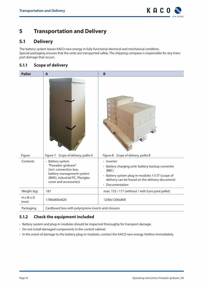
Transportation and Delivery
Operating instructions Powador-gridsave_EN Page 15
Authorised electrician
DANGERRisk of fatal injury if incompatible components are usedThe battery and power electronics can be damaged if different delivery batches are combined and will carry potentially fatal voltages if connected rsaquo Assemble the system using the components provided by KACO new energy only rsaquo Check the serial numbers on the delivery document against the serial numbers of the individual
units on pallets A and B
52 StorageIncorrect storage can lead to system malfunctions Therefore please observe the following conditionsbull If storing for longer than six months store the device in an interior room in its original packaging bull If the original packaging has been removed store the device in a cool dry interior roombull Storage temperature -20 degC to +70 degCbull Relative humidity 0 to 95 (non-condensing)bull If the device is stored for a relatively long time at high humidity the device must be left for more than one day to
dry out sufficiently before connection to the power grid
53 Transportation
WARNINGImpact hazard risk of breakage to the components in the battery systemThe centre of gravity is located in the upper part of the device rsaquo Transport the device upright together with the pallet rsaquo Do not expose the device or components to any shocks rsaquo After unloading at least two people are required to transport the cabinet
WARNINGDanger due to impact and incorrect storage of the batteriesIn the event of damage batteries can release hazardous electrolyte gases which will cause irreversible burns if they come into contact with the skin rsaquo Transport the batteries in the vendors original packaging only rsaquo Remove the batteries from the original packaging shortly before installation rsaquo Do not store batteries in cars or outdoors rsaquo Check the condition of the battery before use
NOTEThe precise specifications of the UN on the transport of lithium batteries can be found under the designation Model Regulations on the transport of dangerous goods Ref STSGAC101 Recommendations on the transport of dangerous goods Part III sub-section 383 ldquoManual of Tests and Criteriardquo Ref STSGAC1011
Assembling the device
Page 16 Operating instructions Powador-gridsave_EN
Authorised electrician
6 Assembling the device
61 Installation
DANGERRisk of fatal injury from fire or explosionsFire caused by flammable or explosive materials in the vicinity of the battery system can lead to serious injuries rsaquo Do not mount the inverter in potentially explosive atmospheres or in the vicinity of highly flamma-
ble materials
CAUTIONBattery system is very heavy ndash risk of injury rsaquo Be aware of the weight of the battery system during transport rsaquo Select suitable mounting location and mounting base rsaquo Only install the battery system with the help of a second person
CAUTIONEquipment damage caused by aggressive gases in combination with humidityThe housing may be seriously damaged by aggressive gases (ammonia sulphur and other chemi-cals) in combination with ambient humidity caused by weather conditions - Installation in rooms containing aggressive gases is not permitted
NOTEAccess in the event of maintenance or serviceAny additional costs arising from unfavourable structural or mounting conditions in the event of a KACO service call-out shall be billed to the customer
611 Installation location
bull Dry well ventilated the waste heat must be conducted away from the battery systembull Unobstructed air circulationbull Easily accessible from the front top and sides without requiring additional resourcesbull Indoors protected against direct sunlight and direct water contact
612 Foundation
bull With sufficient load-bearing capacitybull Made from heat-resistant material (up to 90 degC)bull Must be flame resistant
NOTEPower reduction due to heat accumulationIf the recommended minimum clearances are not observed the device may go into power regula-tion mode due to insufficient ventilation and the resulting heat build-up rsaquo The construction and installation of the device may be performed only by a qualified electrician in
accordance with the valid standards and regulations rsaquo Maintain minimum clearances rsaquo Ensure sufficient heat dissipation
Assembling the device
Operating instructions Powador-gridsave_EN Page 17
Authorised electrician
0deg
1000 mm
200 mm 200 mm
500 mm
min carrying capacity 300 kgmsup2
200 mm200 mm
50 mm
Figure 9 Minimum clearances at the installation and assembly location
CAUTIONRisk of injury if the battery system tips overRisk of tipping due to high centre of gravity particularly with the door open rsaquo Anchor the device securely to the floor immediately after installation rsaquo Open the housing door using the enclosed cabinet key only once the device has been securely
anchored
510 mm200 mm
200 mm
400
mm
12 mmmin 110 mm
DesignationHex head wood screw 8x80 DIN571-vz Fischer dowel S12 Flat washer M8 galvanised DIN9021-vz
Units444
Figure 10 Dimensions for anchoring to the floor Table 3 Mounting parts
62 Installing components
CAUTIONAvoid improper handlingImproper handling can cause damage to components rsaquo Damaged components must not be installed rsaquo Always put the plug-in modules down horizontally to avoid damage to the components
Assembling the device
Page 18 Operating instructions Powador-gridsave_EN
Authorised electrician
WARNINGDanger caused by short circuit or sparkingSerious injury from touching or connecting live components rsaquo Damaged components must not be installed
Preparation1 Check the conditions for the installation location2 Open the housing doors using the enclosed cabinet key3 The cables should be professionally laid and prepared for connection4 Follow the installation sequence (1-4 step(s))
621 Step 1 Fit the battery (batteries)
NOTEPlease read the notes on installation and connection in the enclosed manual Features for the battery unit
622 Step 2 Connect battery (batteries) to the battery management system (BMS)
NOTEPlease read the notes on installation and connection in the enclosed manual Features for the battery unit
623 Step 3 Fit the battery charging unit battery backup converter (BBC)
Battery (batteries) connected to the battery management system (BMS)1 Carefully insert battery charging unit battery backup converter (BBC) into the compartment provided for it 2 Push in completely to establish direct contact with the rear busbars3 Secure battery charging unit battery backup converter (BBC) using the screws supplied
624 Step 4 Fit the inverter
Battery charging unit battery backup converter (BBC) is fitted1 Carefully insert inverter into the compartment provided for it 2 Push in completely to establish direct contact with the rear busbars 3 Secure inverter using the screws supplied
CAUTIONDamage to the control unit from introducing foreign objectsForeign objects can impair the function of the control unit and cause damage rsaquo Do not remove the front panel rsaquo Foreign objects should be removed immediately
Installing the device
Operating instructions Powador-gridsave_EN Page 19
Authorised electrician
7 Installing the device
DANGERLethal voltages are still present in the terminals and cables in the device even after switching off and disconnection of the battery systemSevere injuries or death may occur if the cables and terminals in the device are touched The device may only be opened or serviced by an authorised electricianThe device must be completely assembled before being connected electrically rsaquo Observe all safety regulations and current technical connection specifications of the responsible
power supply company rsaquo De-energise the device using the DC isolator switch circuit breaker and residual current circuit
breaker rsaquo Secure both sides against being inadvertently switched back on rsaquo Ensure that the AC and DC sides are completely isolated and voltage free rsaquo Never open the plug-in modules rsaquo Hazardous voltages are present at the busbars rsaquo Disconnect from the grid and plant supply rsaquo First connect the battery system in the connection area
71 Opening the connection area
3
1
2
Figure 11 Open cover plateKey
1 Cover plate 3 Fastening screw
2 Lock
Opening the connection area You have completed assembly
1 Remove the fastening screw for the upper cover plate2 Slide the cover plate forwards out of the lock3 Lift the cover plate upward to remove raquo Make the electrical connection
Installing the device
Page 20 Operating instructions Powador-gridsave_EN
Authorised electrician
72 Making the electrical connectionMake the connection to the PV generator as well as the grid connection using the connection terminals Note the following cable cross-sections
Connection Possible cable cross-section Length of insulation to be stripped offAC home power grid 05 - 16 mmsup2 with end sleeve
05 - 25 mmsup2 without end sleeve18 mm sleeve18-20 mm
PV connection 05 - 16 mmsup2 with end sleeve05 - 25 mmsup2 without end sleeve
18 mm sleeve17-19 mm
Inverter output 05 - 4 mmsup2 with end sleeve05 - 6 mmsup2 without end sleeve
12 mm sleeve11-13 mm
Potential-free contacts 034 - 15 mmsup2 with end sleeve034 - 25 mmsup2 without end sleeve
12 mm sleeve 9-10 mm
Table 4 Cable cross-sections for connection terminals
NOTEThe threaded connections should be matched to the cable cross-section
NOTEOnly conductors and no insulation should be inserted into the connection terminals Individual wires or cables with end sleeves with the appropriate cross-section can be inserted directly into the connection terminal without a toolFine-strand cables without end sleeve or thin conductors will need a screwdriver (plain slot 35 mm) for connection To do this insert the blade of the screwdriver into the recess provided The cable can be inserted into the spring terminal by pressing downwards The spring terminal closes on removal of the screw-driver
Installing the device
Operating instructions Powador-gridsave_EN Page 21
Authorised electrician
X2X1F1 F2 X7 X4 St1
St2
St3
2 3 541 6
Figure 12 View from above of the connection area
Key
1 AC grid input (M40 cable fitting) 4 Network interface (M32 cable fitting)
2 AC grid output (M40 cable fitting) 5 Inverter input (M16 cable fitting)
3 Inverter output (M32 cable fitting) 6 Other connections (M16 cable fitting)
F1 F2 X7 X4 St1
St2
St3
L1 L2 L3 N PE L1 L2 L3 N N PE PE
X1 X2
PV+
PV-
L1 L2 L3 N PE32A 32A PEN
Cust
omer
co
nnec
tion
Figure 13 View from above of the connection area
Key
X1 AC grid input (main junction box meter) X7 PV generator input
X2 AC grid output (building electrical system) F1 F2 Phase bridging fuse
X4 Inverter output St 1-3 Potential-free contacts control outputs
Installing the device
Page 22 Operating instructions Powador-gridsave_EN
Authorised electrician
721 Connecting to the power grid
Because the device is installed between the main junction boxmeter and the buildings electrical system the maxi-mum grid current to the service line must not exceed the rated operating current of the battery system The cable cross-section must be selected in accordance with applicable standards to suit the connected load instal-lation type etc Moreover the terminal area and size of the cable fitting must be noted
NOTEThe fuse rating for the cable should be max 63A (automatic circuit breaker or safety fuse) even if the cross-section of the installed cable would permit a higher fuse rating Always follow the applicable regulations regarding the cable cross-section and installation typeThe device supports standard grid configurations such as TN-C TN-S and TT TN-SIf a TN-S grid is present directly at the power input and output of the device L1-L3 N and PE must each be connected The home power grid should have 4-pin isolationTN-C4-pin grid isolation is factory preset and disconnects L1 L2 L3 and N In a TN-C grid the N conduc-tor must not be disconnected If a TN-S grid is present directly at the power input and output of the device a cable bridge (included in delivery) must be installed between the N terminal on X1 and the N terminal on X2 N and PE must additionally be connected together To do this simply insert the enclosed terminal link into the N and PE terminals TTIn the case of a TT grid L1-L3 N and PE must each be connected The home power grid should have 4-pin isolation
NOTEPlease check with the operator of the mains grid whether there are special regulations for grid connection Grid isolation is factory preset to 4-pin is fail-safe and provided with grid and system protection as per VDE-AR-N 4105
Making the grid connection Use cables with 5 wires (L1 brown L2 black L3 grey N blue PE greenyellow) and the correct
cross-section1 Loosen cable fitting for AC connection2 Remove the outer cladding of the AC cables3 Insert the AC cables through the cable fitting into the connection area4 Strip the insulation from the AC cables5 Remove connection terminals6 Connect the cables in line with the terminal labels (Figure 13 on page 21)7 Close the connection terminals8 Check that all connected cables are securely fitted9 Tighten the cable fitting10 To meet the requirements of protection rating IP21 close the unused cable fittings with blind caps raquo The battery system is connected to the power grid
NOTEAn AC-side disconnection unit must be provided during the final installation stage This disconnec-tion unit must be installed so that it can be accessed at any time without obstruction If a residual current circuit breaker is necessary due to the installation specification a type A residual current circuit breaker must be used
Installing the device
Operating instructions Powador-gridsave_EN Page 23
Authorised electrician
7211 Output from the inverterRecommended cable cross-sections for the inverter output and fuse rating of cables for fixed wiring accord-ing to VDE 0100 part 430The fuse rating for the cable is dependent on the cable cross-section max 40A automatic circuit breaker
NOTEWhen the line resistance is high (ie long grid-side cables) the voltage at the grid terminals of the inverter will increase during feed-in to the grid The inverter monitors this voltage If the voltage exceeds the country-specific grid overvoltage limit value the inverter switches off rsaquo Ensure that the conductor cross-sections are sufficiently large or that the cable lengths are suffi-
ciently short
NOTEIn order to avoid asymmetries in the grid systems with multiple battery systems should be designed so that the inverters in the devices feed into the grid in differing phases rsaquo Follow the connection conditions for the particular type of grid and the schematic illustration
below
Country and grid-type
Grid monitoring Required monitoring
max asymmetry between phases L1L2L3
DE-NSP Three-phase or single phase phase unbalanced load 46 kVA
Table 5 Grid-type-specific connection conditions
L1
L2
L3
N
Connection X1 Connection X1 Connection X1 Connection X1
L1 L2 L3 N PE L1 L2 L3 N PE L1 L2 L3 N PE L1 L2 L3 N PE
Powador-gridsave inverter1 L1 - L1 L2 - L2 L3 - L32 L1 - L2 L2 - L3 L3 - L1 3 L1 - L3 L2 - L1 L3 - L2 4 L1 - L1 L2 - L2 L3 - L3
Figure 14 Grid-side connection for systems with multiple battery systems with three-phase grid monitoring
Installing the device
Page 24 Operating instructions Powador-gridsave_EN
Authorised electrician
722 Connecting the PV generator
Connect the PV generator on the left in the connection area (Figure 13 on page 21) Use the provided M16 cable fittings A maximum of two strings can be connected For this reason a DC string fuse can be dispensed with
DANGERRisk of fatal injury due to contact voltagesRemoving the cables from the terminals without first disconnecting the PV generator from the device can cause serious damage to health or damage to the system rsaquo During installation Electrically disconnect the DC positive and DC negative from the protective
earth (PE) rsaquo Completely de-energise the system (AC home power grid AC circuit breaker residual current circuit
breaker DC isolator switch) rsaquo Disconnect the battery system from the PV generator using the integrated DC isolator switch rsaquo Remove DC plug connectors
NOTEIn accordance with IEC 61730 Class A connected PV modules must be dimensioned for the DC system voltage provided and at least for the value of the AC grid voltage
7221 Before connecting
Ensure that there is no ground fault1 Determine the DC voltage between the
ndash protective earth (PE) and the positive cable of the PV generator and between the ndash protective earth (PE) and the negative cable of the PV generator
If stable voltages can be measured there is a ground fault in the DC generator or its wiring The ratio between the measured voltages gives an indication as to the location of this fault
2 Rectify any faults before taking further measurements3 Determine the electrical resistance between the
ndash protective earth (PE) and the positive cable of the PV generator and between the ndash protective earth (PE) and the negative cable of the PV generator
In addition ensure that the PV generator has a total insulation resistance of more than 20 MOhm since the inverter will not feed in if the insulation resistance is too low
4 Rectify any faults before connecting the DC generator
7222 Connecting the PV generator
DANGERRisk of fatal injury due to electric shockSevere injury or death will result if the live connections are touched When there is solar radiation DC voltage will be present at the open ends of the DC cables rsaquo Do not touch the exposed ends of the cables rsaquo Avoid short circuits
Installing the device
Operating instructions Powador-gridsave_EN Page 25
Authorised electrician
Connecting the PV generator Use cables with the correct cross-section
1 Remove cable fittings for DC connection2 Remove the outer cladding of the DC cables3 Insert the DC cables through the cable fittings into the connection area4 Strip the insulation from the DC cables5 Remove connection terminals6 Connect the cables in line with the terminal labels (See Figure 13 on page 21)7 Close the connection terminals8 Check that all connected cables are securely fitted9 Tighten the cable fittings10 To meet the requirements of protection rating IP21 close the unused cable fittings with blind caps raquo The PV generator is connected to the inverter
73 Connecting the interfaces
731 Ethernet interface
Pre-assembled Ethernet cables can be connected using the RJ45 socket in the connection space
Connecting the Ethernet cable1 Remove closure cap from RJ45 socket2 Connect the Ethernet cable3 The energy management system can now obtain an IP address by DHCP and is also available via this in the
network
NOTEThe network settings can be amended later in the Settings menu using the EMS
NOTEUse a suitable category 5 network cable The maximum length of a network segment is 100 m Ensure that the cable is correctly assigned The Ethernet connection of the battery system supports auto-sensing You can use both crossed and 11 configured Ethernet connection cables
74 Sealing the connection area
1 Finally check the cabling2 Ensure that all cables are firmly mounted3 Check that the cable fitting is secure and tighten if necessary4 Remove cable offcuts and particles of dirt or dust5 Fit the cover and slide back until it engages into position6 Check that the position is correct7 Screw the fastening screw onto the front of the cover
Installing the device
Page 26 Operating instructions Powador-gridsave_EN
Authorised electrician
75 Starting up
DANGERLethal voltages are still present in the terminals and cables in the device even after switching off and disconnection of the battery systemSevere injuries or death may occur if the cables and terminals in the device are touched Only appropriately qualified and authorised electricians may open install or maintain the battery system rsaquo Keep the front doors and covers closed during operation
NOTEInitial start-up should be carried out using the available public AC grid
76 Standard configuration
Factory settingsCountry configuration Germany
Grid guidelines Low voltage directive
Language German
Time UTC +1 Central European Time
User Standard
Network parameters DHCP (network settings will be obtained automatically from the router)
NOTEPlease state the desired power limitation (60 or 70 of the PV system capacity) when you order For other variations please notify your KACO contact so that the parameters can be set at the factory prior to delivery
Installing the device
Operating instructions Powador-gridsave_EN Page 27
Authorised electrician
761 Step 1 AC home power grid
Check all cables and connections before starting up1 Switch on the AC home power grid using the AC main switch raquo Powador-protect measurement and control unit starts up and monitors the AC grid raquo Two green LEDs indicate that the grid parameters are met raquo After a further 60 seconds (shortly after the backlighting in the Powador-protect goes out) the Powador-pro-
tect will switch on the home grid2 Configure Powador-protect according to the enclosed Powador-protect instructions
(The instructions are also available on the website at wwwkaconewenergyde) raquo The AC power is supplied in the normal way by the public grid
762 Step 2 AC supply from the battery system
Check all cables and connections before starting up1 Remove external isolation means from the device2 Switch on the circuit breaker raquo The LCD touchscreen on the front panel comes on and the energy management system (EMS) starts up
3 Switch on the residual current circuit breaker raquo The battery system starts up
763 Step 3 Switch on the PV system
1 Switch on any optional external PV isolator switches2 Set the internal DC isolator switch to ON raquo The inverter and the battery charging unit battery backup converter (BBC) are connected to the PV system raquo The device monitors the PV voltage for approx 60 seconds then optimisation of internal consumption takes
place
764 Step 4 Switch on batteries
NOTEPlease read the additional information in the enclosed manual Features for the battery unit
765 Step 5 Activate energy management
NOTEKACO new energy cannot provide any support for problems regarding the IT infrastructure (eg router configuration IP address assignment ports etc) as the structure settings and configuration of the network environment can be complex and very different from place to place In the event of any problems please contact an IT service provider
Remote access activated 1 Please call the KACO Hotline to make an appointment for activation of energy management
Configuration and Operation
Page 28 Operating instructions Powador-gridsave_EN
Authorised electrician
8 Configuration and Operation
81 ControlsThe battery system is fitted with a touchscreen which allows it to be controlled very precisely In normal operation the display is switched off Touching the screen activates the display and after a configurable period of time without being touched the dis-play will deactivate If the screen-save function is switched off the touchscreen will be on continuously
NOTEDepending on the tolerances of the measuring elements the measured and displayed values are not always the actual values However the measuring elements ensure maximum solar yield Due to these tolerances the daily yields shown on the touchscreen may deviate from the values on the grid operatorrsquos feed-in meter by up to 15
3
1
45
2
Figure 15 Overview (home screen)
Key
1 Home button 4 Current time
2 System components 5 Menu name
3 More information
811 Information about the system
Open start screen View changesjumps to the home screen
Show component detail Parameters of the selected component
Settings Define settings for the active user
raquo Displays settings
Configuration and Operation
Operating instructions Powador-gridsave_EN Page 29
Controls Left arrow jump back to previous menu item Up and down arrows navigate through the menu or change a value
Left arrow displayed value is reduced by one increment Right arrow displayed value is increased by one increment or change to the submenu
Display fields Grey box Text or figures (not selectable) Blue box Calls up submenu for the display in question
Activate and deactivate Activate function by ticking the box
Table 6 Information about the system
812 System components
PV generator Display of the current generator data
power voltage current temperature in the inverter
Battery Display of the current battery status
power (charging or discharging) voltage current charge status available capacity temperature of battery
Grid Display of the following either fed-in or drawn from the grid
power voltage current for phase L1-L3 total output frequency
Consumer (load) Display of the consumer data
power voltage current for phase L1-L3 total output
Energy flow raquo Displays the current energy flow in the system
Table 7 Information about system components
Configuration and Operation
Page 30 Operating instructions Powador-gridsave_EN
813 Menu structure
Icons used
Display menu Submenu
Option menu
Menu Submenu Display setting
Action in this menumeaning
PV generator Details
Power Displays the current DC-side power
Voltage Displays the current DC-side voltage
Current Displays the current DC-side amperage
Temp inverter
Displays the current temperature in the inverter housing
Battery Details
Power Displays the current AC-side power
Voltage Displays the current AC-side voltage
Current Displays the current AC-side amperage
Charge status Displays the current charge status
Capacity Displays the current battery capacity
Temperature Displays the current measured temperature of the battery
Grid Details
Power Displays the current AC-side power being drawn or fed-in
Voltage Displays the AC-side voltage being applied
Current Displays the current AC-side amperage being drawn or fed-in
Total output Displays the current AC-side total output being drawn or fed-in
Frequency Displays the frequency currently being applied to the grid junction
Consumer (load) Details
Power Displays the current AC-side power being drawn
Voltage Displays the current AC-side voltage being applied
Current Displays the current AC-side amperage being drawn
Total output Displays the current AC-side total output being drawn
Configuration and Operation
Operating instructions Powador-gridsave_EN Page 31
Menu Submenu Display setting
Action in this menumeaning
Settings
Country amp directive display
Display of the country settings voltage directives and grid type
Select menu language
DateTime Specify time zone date format and date and time
Screen Activate screen-save function and set the delay period
Network settings
Display of the network settings Configure network settings Once the DHCP server becomes available the IP
address subnet mask gateway and DNS server are automatically applied and the aforemen-tioned menu items are hidden
Off DHCP deactivated make settings manually
Version Displays the installed software version and built-in HW components (inverter BBC battery)
Vendor The touchscreen shows information about the device vendor
NOTEAs changes to the software are possible after the manual has been printed the illustrations and descriptions of the functions in these operating instructions may deviate from the software Please therefore note the current Application Notes on our website
MaintenanceTroubleshooting
Page 32 Operating instructions Powador-gridsave_EN
9 MaintenanceTroubleshooting
91 Visual inspectionInspect the device and the cables for visible external damage and note the operating status display In case of damage notify your installer Repairs may only be carried out by authorised electricians
NOTEThe battery system should be checked for proper operation by a qualified electrician at regular intervals
92 Cleaning the device
DANGERLethal voltages in the battery systemSerious injuries or death can result if moisture enters the system rsaquo Only use completely dry objects to clean the battery system rsaquo Only clean the outside of the battery system
Cleaning the battery system Do not use compressed air Use a vacuum cleaner or a soft brush to remove dust from the fan cover and from the top of the inverter on a
regular basis Remove dust from the ventilation inlets if necessary
MaintenanceTroubleshooting
Operating instructions Powador-gridsave_EN Page 33
Authorised electrician
93 Maintenance
DANGERLethal voltages are still present in the terminals and cables in the device even after switching off and disconnection of the battery systemSevere injuries or death may occur if the cables and terminals in the device are touched The device is only permitted to be opened or serviced by an authorised electrician rsaquo Observe all safety regulations and the current technical connection specifications from the relevant
power supply company rsaquo Disconnect the AC and DC sides rsaquo Secure the AC and DC sides from being inadvertently switched back on rsaquo Only then should the device be opened rsaquo After shutdown wait at least 30 minutes before working on the device
CAUTIONDestruction of the DC connectionThe connection terminals can be destroyed by arcing if disconnected while still live rsaquo It is absolutely essential that the shutdown sequence be carried out in the correct order (See sec-
tion 111 on page 35)
94 Faults
941 Procedure
DANGERLethal voltages are still present in the terminals and cables in the device even after switching off and disconnection of the battery systemSevere injuries or death may occur if the cables and terminals in the device are touched
When a fault occurs notify an appropriately authorised and qualified electrician or KACO new energy GmbH Service
Service
Page 34 Operating instructions Powador-gridsave_EN
10 ServiceIf you need help solving a technical problem with one of our KACO products please contact our service hotline
Please have the following information ready so that we can help you quickly and efficientlybull Serial nobull SW version of the components (the software version can be found in the Settings menu using the EMS)bull Module type and string circuitbull Date of installation Start-up reportbull Consignment identification Delivery address Contact person (with telephone number)bull Information about the accessibility of the installation site
Any additional costs arising from unfavourable structural or mounting conditions shall be billed to the customer
You can find our warranty conditions on our websitehttpkaco-newenergycomservicewarrantyFrom there you can easily navigate to our international websites by clicking on the appropriate flag
Please use our website to register your unit immediatelyYou can also select the appropriate flag on this page to access the website for your own countryIn this manner you can assist us in providing you with the quickest service possible Note The maximum length of the warranty is based on the currently applicable national warranty conditions
We have prepared a template for complaints This can be found at httpskaco-newenergycomservicecustomer-service
Hotlines
Technical troubleshooting Technical consultation
Inverters and battery systems ()
+49 (0) 71323818-660 +49 (0) 71323818-660
Data logging and accessories +49 (0) 71323818-690 +49 (0) 71323818-690
Construction site emergency () +49 (0) 71323818-630
Customer help desk Monday to Friday from 730 am to 530 pm (CET)
() Also on Saturdays from 800 am to 200 pm (CET)
ShutdownDisassembly
Operating instructions Powador-gridsave_EN Page 35
11 ShutdownDisassembly
111 Switching off the device
DANGERLethal voltages are still present in the terminals and cables even after switching off and discon-nection of the battery systemSevere injuries or death may occur if the cables and terminals in the device are touched rsaquo Complete de-energisation only occurs if the bulk power supply is switched off upstream of the bat-
tery system
DANGERDestruction of the DC plug connectorDC plug connectors can be destroyed by arcing if disconnected while still live rsaquo It is absolutely essential that the following shutdown sequence is observed
1111 Step 1 Shutting down the PV system
1 Switch off any optional external PV isolator switches2 Set the internal DC isolator switch to OFF raquo The inverter and battery charging unit battery backup converter (BBC) are disconnected
1112 Step 2 Disconnect the batteries
NOTEPlease read the additional information in the enclosed manual Features for the battery unit
1113 Step 3 Disconnect the AC supply
1 Connect external isolation means to the device2 Switch off the circuit breaker 3 Switch off the residual current circuit breaker raquo The battery system is switched off
1114 Step 4 AC home power grid
1 Shutdown the AC home power grid using the AC main switch raquo The battery system can be uninstalled
Disposal
Page 36 Operating instructions Powador-gridsave_EN
112 Uninstalling the device
NOTETo uninstall follow the same sequence as for installation but in reverse order
Switch off the device1 Unlock and open the housing door2 Remove the upper cover3 Release the DC and AC cables from the connection terminals4 Pull out the cables raquo The battery system is uninstalled Continue with the disassembly
113 Disassembling the device
NOTETo disassemble follow the same sequence as for assembly but in reverse order
Switch off the device1 Uninstall the components2 Remove the fastening from the device3 Securely pack up the battery system if it is to be used later
or have the battery system disposed of in accordance with section 12 on page 36
12 DisposalFor the most part both the battery system and the corresponding transport packaging are made from recyclable raw materialsBatteries and components Do not dispose of faulty batteries or the components together with household waste Ensure that the old device and accessories are disposed of in a proper mannerPackaging Ensure that the transport packaging is disposed of properlyBatteriesUsed or faulty batteries must be transported in special packaging If you need such packaging please contact the KACO Hotline
NOTEPlease read the additional information in the enclosed manual Features for the battery unit
Appendix
Operating instructions Powador-gridsave_EN Page 37
13 Appendix
EU Declaration of Conformity
Vendorrsquos name and address
KACO new energy GmbH Carl-Zeiss-Straszlige 1 74172 Neckarsulm Germany
Product description Battery system
Type designation Powador-gridsave 135 kWh 6400 Powador-gridsave 135 kWh 8000
Powador-gridsave 270 kWh 6400 Powador-gridsave 270 kWh 8000
Powador-gridsave 405 kWh 6400 Powador-gridsave 405 kWh 8000
Powador-gridsave 540 kWh 6400 Powador-gridsave 540 kWh 8000
Powador-gridsave 577 kWh 6400 Powador-gridsave 577 kWh 8000
Powador-gridsave 675 kWh 6400 Powador-gridsave 675 kWh 8000
This is to confirm that the units listed above comply with the protection requirements set forth in the Directive of the Council of the European Union of 15th December 2004 on the harmonisation of the laws of the member states relating to Electromagnetic Compatibility (2004108EC) and the Low Voltage Directive (200695EC)The units are compliant with the following standards
200695EC ldquoDirective relating to electrical equipment designed for use within specific voltage limitsrdquo
Safety of the unitIEC 62109-12010IEC 62109-22011
2004108EC ldquoDirective relating to electromagneticcompatibilityrdquo
Interference immunityEN 61000-6-22005 Emitted interferenceEN 61000-6-32007
Secondary effects on the gridEN 61000-3-112000EN 61000-3-122005
The types mentioned above are therefore labelled with the CE markUnauthorised modifications to the supplied units andor any use of the units that is contrary to their intended use render this Declaration of Conformity null and void
Neckarsulm 0711 2013KACO new energy GmbH
pp Volker DietrichEnergy systems engineering management
Disposal
Page 38 Operating instructions Powador-gridsave_EN
Carl-Zeiss-Straszlige 1 middot 74172 Neckarsulm middot Germany middot Phone +49 7132 3818-0 middot Fax +49 7132 3818-703 middot infokaco-newenergyde middot wwwkaco-newenergyde
The
text
and
figu
res
refle
ct th
e cu
rren
t tec
hnic
al s
tate
at t
he ti
me
of p
rintin
g S
ubje
ct to
tech
nica
l cha
nges
Err
ors
and
omis
sion
s ex
cept
ed
3006
856-
01-1
4030
5
- 1General Information
-
- 11About this document
- 12Name plate
- 13Additional information
- 14Intended use
-
- 2Safety
-
- 21Protection features
-
- 3Description
-
- 31Mode of Operation
- 32Summary of the components
-
- 4Technical Data
-
- 41Electrical data
- 42Mechanical data
-
- 5Transportation and Delivery
-
- 51Delivery
- 52Storage
- 53Transportation
-
- 6Assembling the device
-
- 61Installation
- 62Installing components
-
- 7Installing the device
-
- 71Opening the connection area
- 72Making the electrical connection
- 73Connecting the interfaces
- 74Sealing the connection area
- 75Starting up
- 76Standard configuration
-
- 8Configuration and Operation
-
- 81Controls
-
- 9MaintenanceTroubleshooting
-
- 91Visual inspection
- 92Cleaning the device
- 93Maintenance
- 94Faults
-
- 10Service
- 11ShutdownDisassembly
-
- 111Switching off the device
- 112Uninstalling the device
- 113Disassembling the device
-
- 12Disposal
- 13Appendix
-

Assembling the device
Page 18 Operating instructions Powador-gridsave_EN
Authorised electrician
WARNINGDanger caused by short circuit or sparkingSerious injury from touching or connecting live components rsaquo Damaged components must not be installed
Preparation1 Check the conditions for the installation location2 Open the housing doors using the enclosed cabinet key3 The cables should be professionally laid and prepared for connection4 Follow the installation sequence (1-4 step(s))
621 Step 1 Fit the battery (batteries)
NOTEPlease read the notes on installation and connection in the enclosed manual Features for the battery unit
622 Step 2 Connect battery (batteries) to the battery management system (BMS)
NOTEPlease read the notes on installation and connection in the enclosed manual Features for the battery unit
623 Step 3 Fit the battery charging unit battery backup converter (BBC)
Battery (batteries) connected to the battery management system (BMS)1 Carefully insert battery charging unit battery backup converter (BBC) into the compartment provided for it 2 Push in completely to establish direct contact with the rear busbars3 Secure battery charging unit battery backup converter (BBC) using the screws supplied
624 Step 4 Fit the inverter
Battery charging unit battery backup converter (BBC) is fitted1 Carefully insert inverter into the compartment provided for it 2 Push in completely to establish direct contact with the rear busbars 3 Secure inverter using the screws supplied
CAUTIONDamage to the control unit from introducing foreign objectsForeign objects can impair the function of the control unit and cause damage rsaquo Do not remove the front panel rsaquo Foreign objects should be removed immediately
Installing the device
Operating instructions Powador-gridsave_EN Page 19
Authorised electrician
7 Installing the device
DANGERLethal voltages are still present in the terminals and cables in the device even after switching off and disconnection of the battery systemSevere injuries or death may occur if the cables and terminals in the device are touched The device may only be opened or serviced by an authorised electricianThe device must be completely assembled before being connected electrically rsaquo Observe all safety regulations and current technical connection specifications of the responsible
power supply company rsaquo De-energise the device using the DC isolator switch circuit breaker and residual current circuit
breaker rsaquo Secure both sides against being inadvertently switched back on rsaquo Ensure that the AC and DC sides are completely isolated and voltage free rsaquo Never open the plug-in modules rsaquo Hazardous voltages are present at the busbars rsaquo Disconnect from the grid and plant supply rsaquo First connect the battery system in the connection area
71 Opening the connection area
3
1
2
Figure 11 Open cover plateKey
1 Cover plate 3 Fastening screw
2 Lock
Opening the connection area You have completed assembly
1 Remove the fastening screw for the upper cover plate2 Slide the cover plate forwards out of the lock3 Lift the cover plate upward to remove raquo Make the electrical connection
Installing the device
Page 20 Operating instructions Powador-gridsave_EN
Authorised electrician
72 Making the electrical connectionMake the connection to the PV generator as well as the grid connection using the connection terminals Note the following cable cross-sections
Connection Possible cable cross-section Length of insulation to be stripped offAC home power grid 05 - 16 mmsup2 with end sleeve
05 - 25 mmsup2 without end sleeve18 mm sleeve18-20 mm
PV connection 05 - 16 mmsup2 with end sleeve05 - 25 mmsup2 without end sleeve
18 mm sleeve17-19 mm
Inverter output 05 - 4 mmsup2 with end sleeve05 - 6 mmsup2 without end sleeve
12 mm sleeve11-13 mm
Potential-free contacts 034 - 15 mmsup2 with end sleeve034 - 25 mmsup2 without end sleeve
12 mm sleeve 9-10 mm
Table 4 Cable cross-sections for connection terminals
NOTEThe threaded connections should be matched to the cable cross-section
NOTEOnly conductors and no insulation should be inserted into the connection terminals Individual wires or cables with end sleeves with the appropriate cross-section can be inserted directly into the connection terminal without a toolFine-strand cables without end sleeve or thin conductors will need a screwdriver (plain slot 35 mm) for connection To do this insert the blade of the screwdriver into the recess provided The cable can be inserted into the spring terminal by pressing downwards The spring terminal closes on removal of the screw-driver
Installing the device
Operating instructions Powador-gridsave_EN Page 21
Authorised electrician
X2X1F1 F2 X7 X4 St1
St2
St3
2 3 541 6
Figure 12 View from above of the connection area
Key
1 AC grid input (M40 cable fitting) 4 Network interface (M32 cable fitting)
2 AC grid output (M40 cable fitting) 5 Inverter input (M16 cable fitting)
3 Inverter output (M32 cable fitting) 6 Other connections (M16 cable fitting)
F1 F2 X7 X4 St1
St2
St3
L1 L2 L3 N PE L1 L2 L3 N N PE PE
X1 X2
PV+
PV-
L1 L2 L3 N PE32A 32A PEN
Cust
omer
co
nnec
tion
Figure 13 View from above of the connection area
Key
X1 AC grid input (main junction box meter) X7 PV generator input
X2 AC grid output (building electrical system) F1 F2 Phase bridging fuse
X4 Inverter output St 1-3 Potential-free contacts control outputs
Installing the device
Page 22 Operating instructions Powador-gridsave_EN
Authorised electrician
721 Connecting to the power grid
Because the device is installed between the main junction boxmeter and the buildings electrical system the maxi-mum grid current to the service line must not exceed the rated operating current of the battery system The cable cross-section must be selected in accordance with applicable standards to suit the connected load instal-lation type etc Moreover the terminal area and size of the cable fitting must be noted
NOTEThe fuse rating for the cable should be max 63A (automatic circuit breaker or safety fuse) even if the cross-section of the installed cable would permit a higher fuse rating Always follow the applicable regulations regarding the cable cross-section and installation typeThe device supports standard grid configurations such as TN-C TN-S and TT TN-SIf a TN-S grid is present directly at the power input and output of the device L1-L3 N and PE must each be connected The home power grid should have 4-pin isolationTN-C4-pin grid isolation is factory preset and disconnects L1 L2 L3 and N In a TN-C grid the N conduc-tor must not be disconnected If a TN-S grid is present directly at the power input and output of the device a cable bridge (included in delivery) must be installed between the N terminal on X1 and the N terminal on X2 N and PE must additionally be connected together To do this simply insert the enclosed terminal link into the N and PE terminals TTIn the case of a TT grid L1-L3 N and PE must each be connected The home power grid should have 4-pin isolation
NOTEPlease check with the operator of the mains grid whether there are special regulations for grid connection Grid isolation is factory preset to 4-pin is fail-safe and provided with grid and system protection as per VDE-AR-N 4105
Making the grid connection Use cables with 5 wires (L1 brown L2 black L3 grey N blue PE greenyellow) and the correct
cross-section1 Loosen cable fitting for AC connection2 Remove the outer cladding of the AC cables3 Insert the AC cables through the cable fitting into the connection area4 Strip the insulation from the AC cables5 Remove connection terminals6 Connect the cables in line with the terminal labels (Figure 13 on page 21)7 Close the connection terminals8 Check that all connected cables are securely fitted9 Tighten the cable fitting10 To meet the requirements of protection rating IP21 close the unused cable fittings with blind caps raquo The battery system is connected to the power grid
NOTEAn AC-side disconnection unit must be provided during the final installation stage This disconnec-tion unit must be installed so that it can be accessed at any time without obstruction If a residual current circuit breaker is necessary due to the installation specification a type A residual current circuit breaker must be used
Installing the device
Operating instructions Powador-gridsave_EN Page 23
Authorised electrician
7211 Output from the inverterRecommended cable cross-sections for the inverter output and fuse rating of cables for fixed wiring accord-ing to VDE 0100 part 430The fuse rating for the cable is dependent on the cable cross-section max 40A automatic circuit breaker
NOTEWhen the line resistance is high (ie long grid-side cables) the voltage at the grid terminals of the inverter will increase during feed-in to the grid The inverter monitors this voltage If the voltage exceeds the country-specific grid overvoltage limit value the inverter switches off rsaquo Ensure that the conductor cross-sections are sufficiently large or that the cable lengths are suffi-
ciently short
NOTEIn order to avoid asymmetries in the grid systems with multiple battery systems should be designed so that the inverters in the devices feed into the grid in differing phases rsaquo Follow the connection conditions for the particular type of grid and the schematic illustration
below
Country and grid-type
Grid monitoring Required monitoring
max asymmetry between phases L1L2L3
DE-NSP Three-phase or single phase phase unbalanced load 46 kVA
Table 5 Grid-type-specific connection conditions
L1
L2
L3
N
Connection X1 Connection X1 Connection X1 Connection X1
L1 L2 L3 N PE L1 L2 L3 N PE L1 L2 L3 N PE L1 L2 L3 N PE
Powador-gridsave inverter1 L1 - L1 L2 - L2 L3 - L32 L1 - L2 L2 - L3 L3 - L1 3 L1 - L3 L2 - L1 L3 - L2 4 L1 - L1 L2 - L2 L3 - L3
Figure 14 Grid-side connection for systems with multiple battery systems with three-phase grid monitoring
Installing the device
Page 24 Operating instructions Powador-gridsave_EN
Authorised electrician
722 Connecting the PV generator
Connect the PV generator on the left in the connection area (Figure 13 on page 21) Use the provided M16 cable fittings A maximum of two strings can be connected For this reason a DC string fuse can be dispensed with
DANGERRisk of fatal injury due to contact voltagesRemoving the cables from the terminals without first disconnecting the PV generator from the device can cause serious damage to health or damage to the system rsaquo During installation Electrically disconnect the DC positive and DC negative from the protective
earth (PE) rsaquo Completely de-energise the system (AC home power grid AC circuit breaker residual current circuit
breaker DC isolator switch) rsaquo Disconnect the battery system from the PV generator using the integrated DC isolator switch rsaquo Remove DC plug connectors
NOTEIn accordance with IEC 61730 Class A connected PV modules must be dimensioned for the DC system voltage provided and at least for the value of the AC grid voltage
7221 Before connecting
Ensure that there is no ground fault1 Determine the DC voltage between the
ndash protective earth (PE) and the positive cable of the PV generator and between the ndash protective earth (PE) and the negative cable of the PV generator
If stable voltages can be measured there is a ground fault in the DC generator or its wiring The ratio between the measured voltages gives an indication as to the location of this fault
2 Rectify any faults before taking further measurements3 Determine the electrical resistance between the
ndash protective earth (PE) and the positive cable of the PV generator and between the ndash protective earth (PE) and the negative cable of the PV generator
In addition ensure that the PV generator has a total insulation resistance of more than 20 MOhm since the inverter will not feed in if the insulation resistance is too low
4 Rectify any faults before connecting the DC generator
7222 Connecting the PV generator
DANGERRisk of fatal injury due to electric shockSevere injury or death will result if the live connections are touched When there is solar radiation DC voltage will be present at the open ends of the DC cables rsaquo Do not touch the exposed ends of the cables rsaquo Avoid short circuits
Installing the device
Operating instructions Powador-gridsave_EN Page 25
Authorised electrician
Connecting the PV generator Use cables with the correct cross-section
1 Remove cable fittings for DC connection2 Remove the outer cladding of the DC cables3 Insert the DC cables through the cable fittings into the connection area4 Strip the insulation from the DC cables5 Remove connection terminals6 Connect the cables in line with the terminal labels (See Figure 13 on page 21)7 Close the connection terminals8 Check that all connected cables are securely fitted9 Tighten the cable fittings10 To meet the requirements of protection rating IP21 close the unused cable fittings with blind caps raquo The PV generator is connected to the inverter
73 Connecting the interfaces
731 Ethernet interface
Pre-assembled Ethernet cables can be connected using the RJ45 socket in the connection space
Connecting the Ethernet cable1 Remove closure cap from RJ45 socket2 Connect the Ethernet cable3 The energy management system can now obtain an IP address by DHCP and is also available via this in the
network
NOTEThe network settings can be amended later in the Settings menu using the EMS
NOTEUse a suitable category 5 network cable The maximum length of a network segment is 100 m Ensure that the cable is correctly assigned The Ethernet connection of the battery system supports auto-sensing You can use both crossed and 11 configured Ethernet connection cables
74 Sealing the connection area
1 Finally check the cabling2 Ensure that all cables are firmly mounted3 Check that the cable fitting is secure and tighten if necessary4 Remove cable offcuts and particles of dirt or dust5 Fit the cover and slide back until it engages into position6 Check that the position is correct7 Screw the fastening screw onto the front of the cover
Installing the device
Page 26 Operating instructions Powador-gridsave_EN
Authorised electrician
75 Starting up
DANGERLethal voltages are still present in the terminals and cables in the device even after switching off and disconnection of the battery systemSevere injuries or death may occur if the cables and terminals in the device are touched Only appropriately qualified and authorised electricians may open install or maintain the battery system rsaquo Keep the front doors and covers closed during operation
NOTEInitial start-up should be carried out using the available public AC grid
76 Standard configuration
Factory settingsCountry configuration Germany
Grid guidelines Low voltage directive
Language German
Time UTC +1 Central European Time
User Standard
Network parameters DHCP (network settings will be obtained automatically from the router)
NOTEPlease state the desired power limitation (60 or 70 of the PV system capacity) when you order For other variations please notify your KACO contact so that the parameters can be set at the factory prior to delivery
Installing the device
Operating instructions Powador-gridsave_EN Page 27
Authorised electrician
761 Step 1 AC home power grid
Check all cables and connections before starting up1 Switch on the AC home power grid using the AC main switch raquo Powador-protect measurement and control unit starts up and monitors the AC grid raquo Two green LEDs indicate that the grid parameters are met raquo After a further 60 seconds (shortly after the backlighting in the Powador-protect goes out) the Powador-pro-
tect will switch on the home grid2 Configure Powador-protect according to the enclosed Powador-protect instructions
(The instructions are also available on the website at wwwkaconewenergyde) raquo The AC power is supplied in the normal way by the public grid
762 Step 2 AC supply from the battery system
Check all cables and connections before starting up1 Remove external isolation means from the device2 Switch on the circuit breaker raquo The LCD touchscreen on the front panel comes on and the energy management system (EMS) starts up
3 Switch on the residual current circuit breaker raquo The battery system starts up
763 Step 3 Switch on the PV system
1 Switch on any optional external PV isolator switches2 Set the internal DC isolator switch to ON raquo The inverter and the battery charging unit battery backup converter (BBC) are connected to the PV system raquo The device monitors the PV voltage for approx 60 seconds then optimisation of internal consumption takes
place
764 Step 4 Switch on batteries
NOTEPlease read the additional information in the enclosed manual Features for the battery unit
765 Step 5 Activate energy management
NOTEKACO new energy cannot provide any support for problems regarding the IT infrastructure (eg router configuration IP address assignment ports etc) as the structure settings and configuration of the network environment can be complex and very different from place to place In the event of any problems please contact an IT service provider
Remote access activated 1 Please call the KACO Hotline to make an appointment for activation of energy management
Configuration and Operation
Page 28 Operating instructions Powador-gridsave_EN
Authorised electrician
8 Configuration and Operation
81 ControlsThe battery system is fitted with a touchscreen which allows it to be controlled very precisely In normal operation the display is switched off Touching the screen activates the display and after a configurable period of time without being touched the dis-play will deactivate If the screen-save function is switched off the touchscreen will be on continuously
NOTEDepending on the tolerances of the measuring elements the measured and displayed values are not always the actual values However the measuring elements ensure maximum solar yield Due to these tolerances the daily yields shown on the touchscreen may deviate from the values on the grid operatorrsquos feed-in meter by up to 15
3
1
45
2
Figure 15 Overview (home screen)
Key
1 Home button 4 Current time
2 System components 5 Menu name
3 More information
811 Information about the system
Open start screen View changesjumps to the home screen
Show component detail Parameters of the selected component
Settings Define settings for the active user
raquo Displays settings
Configuration and Operation
Operating instructions Powador-gridsave_EN Page 29
Controls Left arrow jump back to previous menu item Up and down arrows navigate through the menu or change a value
Left arrow displayed value is reduced by one increment Right arrow displayed value is increased by one increment or change to the submenu
Display fields Grey box Text or figures (not selectable) Blue box Calls up submenu for the display in question
Activate and deactivate Activate function by ticking the box
Table 6 Information about the system
812 System components
PV generator Display of the current generator data
power voltage current temperature in the inverter
Battery Display of the current battery status
power (charging or discharging) voltage current charge status available capacity temperature of battery
Grid Display of the following either fed-in or drawn from the grid
power voltage current for phase L1-L3 total output frequency
Consumer (load) Display of the consumer data
power voltage current for phase L1-L3 total output
Energy flow raquo Displays the current energy flow in the system
Table 7 Information about system components
Configuration and Operation
Page 30 Operating instructions Powador-gridsave_EN
813 Menu structure
Icons used
Display menu Submenu
Option menu
Menu Submenu Display setting
Action in this menumeaning
PV generator Details
Power Displays the current DC-side power
Voltage Displays the current DC-side voltage
Current Displays the current DC-side amperage
Temp inverter
Displays the current temperature in the inverter housing
Battery Details
Power Displays the current AC-side power
Voltage Displays the current AC-side voltage
Current Displays the current AC-side amperage
Charge status Displays the current charge status
Capacity Displays the current battery capacity
Temperature Displays the current measured temperature of the battery
Grid Details
Power Displays the current AC-side power being drawn or fed-in
Voltage Displays the AC-side voltage being applied
Current Displays the current AC-side amperage being drawn or fed-in
Total output Displays the current AC-side total output being drawn or fed-in
Frequency Displays the frequency currently being applied to the grid junction
Consumer (load) Details
Power Displays the current AC-side power being drawn
Voltage Displays the current AC-side voltage being applied
Current Displays the current AC-side amperage being drawn
Total output Displays the current AC-side total output being drawn
Configuration and Operation
Operating instructions Powador-gridsave_EN Page 31
Menu Submenu Display setting
Action in this menumeaning
Settings
Country amp directive display
Display of the country settings voltage directives and grid type
Select menu language
DateTime Specify time zone date format and date and time
Screen Activate screen-save function and set the delay period
Network settings
Display of the network settings Configure network settings Once the DHCP server becomes available the IP
address subnet mask gateway and DNS server are automatically applied and the aforemen-tioned menu items are hidden
Off DHCP deactivated make settings manually
Version Displays the installed software version and built-in HW components (inverter BBC battery)
Vendor The touchscreen shows information about the device vendor
NOTEAs changes to the software are possible after the manual has been printed the illustrations and descriptions of the functions in these operating instructions may deviate from the software Please therefore note the current Application Notes on our website
MaintenanceTroubleshooting
Page 32 Operating instructions Powador-gridsave_EN
9 MaintenanceTroubleshooting
91 Visual inspectionInspect the device and the cables for visible external damage and note the operating status display In case of damage notify your installer Repairs may only be carried out by authorised electricians
NOTEThe battery system should be checked for proper operation by a qualified electrician at regular intervals
92 Cleaning the device
DANGERLethal voltages in the battery systemSerious injuries or death can result if moisture enters the system rsaquo Only use completely dry objects to clean the battery system rsaquo Only clean the outside of the battery system
Cleaning the battery system Do not use compressed air Use a vacuum cleaner or a soft brush to remove dust from the fan cover and from the top of the inverter on a
regular basis Remove dust from the ventilation inlets if necessary
MaintenanceTroubleshooting
Operating instructions Powador-gridsave_EN Page 33
Authorised electrician
93 Maintenance
DANGERLethal voltages are still present in the terminals and cables in the device even after switching off and disconnection of the battery systemSevere injuries or death may occur if the cables and terminals in the device are touched The device is only permitted to be opened or serviced by an authorised electrician rsaquo Observe all safety regulations and the current technical connection specifications from the relevant
power supply company rsaquo Disconnect the AC and DC sides rsaquo Secure the AC and DC sides from being inadvertently switched back on rsaquo Only then should the device be opened rsaquo After shutdown wait at least 30 minutes before working on the device
CAUTIONDestruction of the DC connectionThe connection terminals can be destroyed by arcing if disconnected while still live rsaquo It is absolutely essential that the shutdown sequence be carried out in the correct order (See sec-
tion 111 on page 35)
94 Faults
941 Procedure
DANGERLethal voltages are still present in the terminals and cables in the device even after switching off and disconnection of the battery systemSevere injuries or death may occur if the cables and terminals in the device are touched
When a fault occurs notify an appropriately authorised and qualified electrician or KACO new energy GmbH Service
Service
Page 34 Operating instructions Powador-gridsave_EN
10 ServiceIf you need help solving a technical problem with one of our KACO products please contact our service hotline
Please have the following information ready so that we can help you quickly and efficientlybull Serial nobull SW version of the components (the software version can be found in the Settings menu using the EMS)bull Module type and string circuitbull Date of installation Start-up reportbull Consignment identification Delivery address Contact person (with telephone number)bull Information about the accessibility of the installation site
Any additional costs arising from unfavourable structural or mounting conditions shall be billed to the customer
You can find our warranty conditions on our websitehttpkaco-newenergycomservicewarrantyFrom there you can easily navigate to our international websites by clicking on the appropriate flag
Please use our website to register your unit immediatelyYou can also select the appropriate flag on this page to access the website for your own countryIn this manner you can assist us in providing you with the quickest service possible Note The maximum length of the warranty is based on the currently applicable national warranty conditions
We have prepared a template for complaints This can be found at httpskaco-newenergycomservicecustomer-service
Hotlines
Technical troubleshooting Technical consultation
Inverters and battery systems ()
+49 (0) 71323818-660 +49 (0) 71323818-660
Data logging and accessories +49 (0) 71323818-690 +49 (0) 71323818-690
Construction site emergency () +49 (0) 71323818-630
Customer help desk Monday to Friday from 730 am to 530 pm (CET)
() Also on Saturdays from 800 am to 200 pm (CET)
ShutdownDisassembly
Operating instructions Powador-gridsave_EN Page 35
11 ShutdownDisassembly
111 Switching off the device
DANGERLethal voltages are still present in the terminals and cables even after switching off and discon-nection of the battery systemSevere injuries or death may occur if the cables and terminals in the device are touched rsaquo Complete de-energisation only occurs if the bulk power supply is switched off upstream of the bat-
tery system
DANGERDestruction of the DC plug connectorDC plug connectors can be destroyed by arcing if disconnected while still live rsaquo It is absolutely essential that the following shutdown sequence is observed
1111 Step 1 Shutting down the PV system
1 Switch off any optional external PV isolator switches2 Set the internal DC isolator switch to OFF raquo The inverter and battery charging unit battery backup converter (BBC) are disconnected
1112 Step 2 Disconnect the batteries
NOTEPlease read the additional information in the enclosed manual Features for the battery unit
1113 Step 3 Disconnect the AC supply
1 Connect external isolation means to the device2 Switch off the circuit breaker 3 Switch off the residual current circuit breaker raquo The battery system is switched off
1114 Step 4 AC home power grid
1 Shutdown the AC home power grid using the AC main switch raquo The battery system can be uninstalled
Disposal
Page 36 Operating instructions Powador-gridsave_EN
112 Uninstalling the device
NOTETo uninstall follow the same sequence as for installation but in reverse order
Switch off the device1 Unlock and open the housing door2 Remove the upper cover3 Release the DC and AC cables from the connection terminals4 Pull out the cables raquo The battery system is uninstalled Continue with the disassembly
113 Disassembling the device
NOTETo disassemble follow the same sequence as for assembly but in reverse order
Switch off the device1 Uninstall the components2 Remove the fastening from the device3 Securely pack up the battery system if it is to be used later
or have the battery system disposed of in accordance with section 12 on page 36
12 DisposalFor the most part both the battery system and the corresponding transport packaging are made from recyclable raw materialsBatteries and components Do not dispose of faulty batteries or the components together with household waste Ensure that the old device and accessories are disposed of in a proper mannerPackaging Ensure that the transport packaging is disposed of properlyBatteriesUsed or faulty batteries must be transported in special packaging If you need such packaging please contact the KACO Hotline
NOTEPlease read the additional information in the enclosed manual Features for the battery unit
Appendix
Operating instructions Powador-gridsave_EN Page 37
13 Appendix
EU Declaration of Conformity
Vendorrsquos name and address
KACO new energy GmbH Carl-Zeiss-Straszlige 1 74172 Neckarsulm Germany
Product description Battery system
Type designation Powador-gridsave 135 kWh 6400 Powador-gridsave 135 kWh 8000
Powador-gridsave 270 kWh 6400 Powador-gridsave 270 kWh 8000
Powador-gridsave 405 kWh 6400 Powador-gridsave 405 kWh 8000
Powador-gridsave 540 kWh 6400 Powador-gridsave 540 kWh 8000
Powador-gridsave 577 kWh 6400 Powador-gridsave 577 kWh 8000
Powador-gridsave 675 kWh 6400 Powador-gridsave 675 kWh 8000
This is to confirm that the units listed above comply with the protection requirements set forth in the Directive of the Council of the European Union of 15th December 2004 on the harmonisation of the laws of the member states relating to Electromagnetic Compatibility (2004108EC) and the Low Voltage Directive (200695EC)The units are compliant with the following standards
200695EC ldquoDirective relating to electrical equipment designed for use within specific voltage limitsrdquo
Safety of the unitIEC 62109-12010IEC 62109-22011
2004108EC ldquoDirective relating to electromagneticcompatibilityrdquo
Interference immunityEN 61000-6-22005 Emitted interferenceEN 61000-6-32007
Secondary effects on the gridEN 61000-3-112000EN 61000-3-122005
The types mentioned above are therefore labelled with the CE markUnauthorised modifications to the supplied units andor any use of the units that is contrary to their intended use render this Declaration of Conformity null and void
Neckarsulm 0711 2013KACO new energy GmbH
pp Volker DietrichEnergy systems engineering management
Disposal
Page 38 Operating instructions Powador-gridsave_EN
Carl-Zeiss-Straszlige 1 middot 74172 Neckarsulm middot Germany middot Phone +49 7132 3818-0 middot Fax +49 7132 3818-703 middot infokaco-newenergyde middot wwwkaco-newenergyde
The
text
and
figu
res
refle
ct th
e cu
rren
t tec
hnic
al s
tate
at t
he ti
me
of p
rintin
g S
ubje
ct to
tech
nica
l cha
nges
Err
ors
and
omis
sion
s ex
cept
ed
3006
856-
01-1
4030
5
- 1General Information
-
- 11About this document
- 12Name plate
- 13Additional information
- 14Intended use
-
- 2Safety
-
- 21Protection features
-
- 3Description
-
- 31Mode of Operation
- 32Summary of the components
-
- 4Technical Data
-
- 41Electrical data
- 42Mechanical data
-
- 5Transportation and Delivery
-
- 51Delivery
- 52Storage
- 53Transportation
-
- 6Assembling the device
-
- 61Installation
- 62Installing components
-
- 7Installing the device
-
- 71Opening the connection area
- 72Making the electrical connection
- 73Connecting the interfaces
- 74Sealing the connection area
- 75Starting up
- 76Standard configuration
-
- 8Configuration and Operation
-
- 81Controls
-
- 9MaintenanceTroubleshooting
-
- 91Visual inspection
- 92Cleaning the device
- 93Maintenance
- 94Faults
-
- 10Service
- 11ShutdownDisassembly
-
- 111Switching off the device
- 112Uninstalling the device
- 113Disassembling the device
-
- 12Disposal
- 13Appendix
-

Installing the device
Operating instructions Powador-gridsave_EN Page 27
Authorised electrician
761 Step 1 AC home power grid
Check all cables and connections before starting up1 Switch on the AC home power grid using the AC main switch raquo Powador-protect measurement and control unit starts up and monitors the AC grid raquo Two green LEDs indicate that the grid parameters are met raquo After a further 60 seconds (shortly after the backlighting in the Powador-protect goes out) the Powador-pro-
tect will switch on the home grid2 Configure Powador-protect according to the enclosed Powador-protect instructions
(The instructions are also available on the website at wwwkaconewenergyde) raquo The AC power is supplied in the normal way by the public grid
762 Step 2 AC supply from the battery system
Check all cables and connections before starting up1 Remove external isolation means from the device2 Switch on the circuit breaker raquo The LCD touchscreen on the front panel comes on and the energy management system (EMS) starts up
3 Switch on the residual current circuit breaker raquo The battery system starts up
763 Step 3 Switch on the PV system
1 Switch on any optional external PV isolator switches2 Set the internal DC isolator switch to ON raquo The inverter and the battery charging unit battery backup converter (BBC) are connected to the PV system raquo The device monitors the PV voltage for approx 60 seconds then optimisation of internal consumption takes
place
764 Step 4 Switch on batteries
NOTEPlease read the additional information in the enclosed manual Features for the battery unit
765 Step 5 Activate energy management
NOTEKACO new energy cannot provide any support for problems regarding the IT infrastructure (eg router configuration IP address assignment ports etc) as the structure settings and configuration of the network environment can be complex and very different from place to place In the event of any problems please contact an IT service provider
Remote access activated 1 Please call the KACO Hotline to make an appointment for activation of energy management
Configuration and Operation
Page 28 Operating instructions Powador-gridsave_EN
Authorised electrician
8 Configuration and Operation
81 ControlsThe battery system is fitted with a touchscreen which allows it to be controlled very precisely In normal operation the display is switched off Touching the screen activates the display and after a configurable period of time without being touched the dis-play will deactivate If the screen-save function is switched off the touchscreen will be on continuously
NOTEDepending on the tolerances of the measuring elements the measured and displayed values are not always the actual values However the measuring elements ensure maximum solar yield Due to these tolerances the daily yields shown on the touchscreen may deviate from the values on the grid operatorrsquos feed-in meter by up to 15
3
1
45
2
Figure 15 Overview (home screen)
Key
1 Home button 4 Current time
2 System components 5 Menu name
3 More information
811 Information about the system
Open start screen View changesjumps to the home screen
Show component detail Parameters of the selected component
Settings Define settings for the active user
raquo Displays settings
Configuration and Operation
Operating instructions Powador-gridsave_EN Page 29
Controls Left arrow jump back to previous menu item Up and down arrows navigate through the menu or change a value
Left arrow displayed value is reduced by one increment Right arrow displayed value is increased by one increment or change to the submenu
Display fields Grey box Text or figures (not selectable) Blue box Calls up submenu for the display in question
Activate and deactivate Activate function by ticking the box
Table 6 Information about the system
812 System components
PV generator Display of the current generator data
power voltage current temperature in the inverter
Battery Display of the current battery status
power (charging or discharging) voltage current charge status available capacity temperature of battery
Grid Display of the following either fed-in or drawn from the grid
power voltage current for phase L1-L3 total output frequency
Consumer (load) Display of the consumer data
power voltage current for phase L1-L3 total output
Energy flow raquo Displays the current energy flow in the system
Table 7 Information about system components
Configuration and Operation
Page 30 Operating instructions Powador-gridsave_EN
813 Menu structure
Icons used
Display menu Submenu
Option menu
Menu Submenu Display setting
Action in this menumeaning
PV generator Details
Power Displays the current DC-side power
Voltage Displays the current DC-side voltage
Current Displays the current DC-side amperage
Temp inverter
Displays the current temperature in the inverter housing
Battery Details
Power Displays the current AC-side power
Voltage Displays the current AC-side voltage
Current Displays the current AC-side amperage
Charge status Displays the current charge status
Capacity Displays the current battery capacity
Temperature Displays the current measured temperature of the battery
Grid Details
Power Displays the current AC-side power being drawn or fed-in
Voltage Displays the AC-side voltage being applied
Current Displays the current AC-side amperage being drawn or fed-in
Total output Displays the current AC-side total output being drawn or fed-in
Frequency Displays the frequency currently being applied to the grid junction
Consumer (load) Details
Power Displays the current AC-side power being drawn
Voltage Displays the current AC-side voltage being applied
Current Displays the current AC-side amperage being drawn
Total output Displays the current AC-side total output being drawn
Configuration and Operation
Operating instructions Powador-gridsave_EN Page 31
Menu Submenu Display setting
Action in this menumeaning
Settings
Country amp directive display
Display of the country settings voltage directives and grid type
Select menu language
DateTime Specify time zone date format and date and time
Screen Activate screen-save function and set the delay period
Network settings
Display of the network settings Configure network settings Once the DHCP server becomes available the IP
address subnet mask gateway and DNS server are automatically applied and the aforemen-tioned menu items are hidden
Off DHCP deactivated make settings manually
Version Displays the installed software version and built-in HW components (inverter BBC battery)
Vendor The touchscreen shows information about the device vendor
NOTEAs changes to the software are possible after the manual has been printed the illustrations and descriptions of the functions in these operating instructions may deviate from the software Please therefore note the current Application Notes on our website
MaintenanceTroubleshooting
Page 32 Operating instructions Powador-gridsave_EN
9 MaintenanceTroubleshooting
91 Visual inspectionInspect the device and the cables for visible external damage and note the operating status display In case of damage notify your installer Repairs may only be carried out by authorised electricians
NOTEThe battery system should be checked for proper operation by a qualified electrician at regular intervals
92 Cleaning the device
DANGERLethal voltages in the battery systemSerious injuries or death can result if moisture enters the system rsaquo Only use completely dry objects to clean the battery system rsaquo Only clean the outside of the battery system
Cleaning the battery system Do not use compressed air Use a vacuum cleaner or a soft brush to remove dust from the fan cover and from the top of the inverter on a
regular basis Remove dust from the ventilation inlets if necessary
MaintenanceTroubleshooting
Operating instructions Powador-gridsave_EN Page 33
Authorised electrician
93 Maintenance
DANGERLethal voltages are still present in the terminals and cables in the device even after switching off and disconnection of the battery systemSevere injuries or death may occur if the cables and terminals in the device are touched The device is only permitted to be opened or serviced by an authorised electrician rsaquo Observe all safety regulations and the current technical connection specifications from the relevant
power supply company rsaquo Disconnect the AC and DC sides rsaquo Secure the AC and DC sides from being inadvertently switched back on rsaquo Only then should the device be opened rsaquo After shutdown wait at least 30 minutes before working on the device
CAUTIONDestruction of the DC connectionThe connection terminals can be destroyed by arcing if disconnected while still live rsaquo It is absolutely essential that the shutdown sequence be carried out in the correct order (See sec-
tion 111 on page 35)
94 Faults
941 Procedure
DANGERLethal voltages are still present in the terminals and cables in the device even after switching off and disconnection of the battery systemSevere injuries or death may occur if the cables and terminals in the device are touched
When a fault occurs notify an appropriately authorised and qualified electrician or KACO new energy GmbH Service
Service
Page 34 Operating instructions Powador-gridsave_EN
10 ServiceIf you need help solving a technical problem with one of our KACO products please contact our service hotline
Please have the following information ready so that we can help you quickly and efficientlybull Serial nobull SW version of the components (the software version can be found in the Settings menu using the EMS)bull Module type and string circuitbull Date of installation Start-up reportbull Consignment identification Delivery address Contact person (with telephone number)bull Information about the accessibility of the installation site
Any additional costs arising from unfavourable structural or mounting conditions shall be billed to the customer
You can find our warranty conditions on our websitehttpkaco-newenergycomservicewarrantyFrom there you can easily navigate to our international websites by clicking on the appropriate flag
Please use our website to register your unit immediatelyYou can also select the appropriate flag on this page to access the website for your own countryIn this manner you can assist us in providing you with the quickest service possible Note The maximum length of the warranty is based on the currently applicable national warranty conditions
We have prepared a template for complaints This can be found at httpskaco-newenergycomservicecustomer-service
Hotlines
Technical troubleshooting Technical consultation
Inverters and battery systems ()
+49 (0) 71323818-660 +49 (0) 71323818-660
Data logging and accessories +49 (0) 71323818-690 +49 (0) 71323818-690
Construction site emergency () +49 (0) 71323818-630
Customer help desk Monday to Friday from 730 am to 530 pm (CET)
() Also on Saturdays from 800 am to 200 pm (CET)
ShutdownDisassembly
Operating instructions Powador-gridsave_EN Page 35
11 ShutdownDisassembly
111 Switching off the device
DANGERLethal voltages are still present in the terminals and cables even after switching off and discon-nection of the battery systemSevere injuries or death may occur if the cables and terminals in the device are touched rsaquo Complete de-energisation only occurs if the bulk power supply is switched off upstream of the bat-
tery system
DANGERDestruction of the DC plug connectorDC plug connectors can be destroyed by arcing if disconnected while still live rsaquo It is absolutely essential that the following shutdown sequence is observed
1111 Step 1 Shutting down the PV system
1 Switch off any optional external PV isolator switches2 Set the internal DC isolator switch to OFF raquo The inverter and battery charging unit battery backup converter (BBC) are disconnected
1112 Step 2 Disconnect the batteries
NOTEPlease read the additional information in the enclosed manual Features for the battery unit
1113 Step 3 Disconnect the AC supply
1 Connect external isolation means to the device2 Switch off the circuit breaker 3 Switch off the residual current circuit breaker raquo The battery system is switched off
1114 Step 4 AC home power grid
1 Shutdown the AC home power grid using the AC main switch raquo The battery system can be uninstalled
Disposal
Page 36 Operating instructions Powador-gridsave_EN
112 Uninstalling the device
NOTETo uninstall follow the same sequence as for installation but in reverse order
Switch off the device1 Unlock and open the housing door2 Remove the upper cover3 Release the DC and AC cables from the connection terminals4 Pull out the cables raquo The battery system is uninstalled Continue with the disassembly
113 Disassembling the device
NOTETo disassemble follow the same sequence as for assembly but in reverse order
Switch off the device1 Uninstall the components2 Remove the fastening from the device3 Securely pack up the battery system if it is to be used later
or have the battery system disposed of in accordance with section 12 on page 36
12 DisposalFor the most part both the battery system and the corresponding transport packaging are made from recyclable raw materialsBatteries and components Do not dispose of faulty batteries or the components together with household waste Ensure that the old device and accessories are disposed of in a proper mannerPackaging Ensure that the transport packaging is disposed of properlyBatteriesUsed or faulty batteries must be transported in special packaging If you need such packaging please contact the KACO Hotline
NOTEPlease read the additional information in the enclosed manual Features for the battery unit
Appendix
Operating instructions Powador-gridsave_EN Page 37
13 Appendix
EU Declaration of Conformity
Vendorrsquos name and address
KACO new energy GmbH Carl-Zeiss-Straszlige 1 74172 Neckarsulm Germany
Product description Battery system
Type designation Powador-gridsave 135 kWh 6400 Powador-gridsave 135 kWh 8000
Powador-gridsave 270 kWh 6400 Powador-gridsave 270 kWh 8000
Powador-gridsave 405 kWh 6400 Powador-gridsave 405 kWh 8000
Powador-gridsave 540 kWh 6400 Powador-gridsave 540 kWh 8000
Powador-gridsave 577 kWh 6400 Powador-gridsave 577 kWh 8000
Powador-gridsave 675 kWh 6400 Powador-gridsave 675 kWh 8000
This is to confirm that the units listed above comply with the protection requirements set forth in the Directive of the Council of the European Union of 15th December 2004 on the harmonisation of the laws of the member states relating to Electromagnetic Compatibility (2004108EC) and the Low Voltage Directive (200695EC)The units are compliant with the following standards
200695EC ldquoDirective relating to electrical equipment designed for use within specific voltage limitsrdquo
Safety of the unitIEC 62109-12010IEC 62109-22011
2004108EC ldquoDirective relating to electromagneticcompatibilityrdquo
Interference immunityEN 61000-6-22005 Emitted interferenceEN 61000-6-32007
Secondary effects on the gridEN 61000-3-112000EN 61000-3-122005
The types mentioned above are therefore labelled with the CE markUnauthorised modifications to the supplied units andor any use of the units that is contrary to their intended use render this Declaration of Conformity null and void
Neckarsulm 0711 2013KACO new energy GmbH
pp Volker DietrichEnergy systems engineering management
Disposal
Page 38 Operating instructions Powador-gridsave_EN
Carl-Zeiss-Straszlige 1 middot 74172 Neckarsulm middot Germany middot Phone +49 7132 3818-0 middot Fax +49 7132 3818-703 middot infokaco-newenergyde middot wwwkaco-newenergyde
The
text
and
figu
res
refle
ct th
e cu
rren
t tec
hnic
al s
tate
at t
he ti
me
of p
rintin
g S
ubje
ct to
tech
nica
l cha
nges
Err
ors
and
omis
sion
s ex
cept
ed
3006
856-
01-1
4030
5
- 1General Information
-
- 11About this document
- 12Name plate
- 13Additional information
- 14Intended use
-
- 2Safety
-
- 21Protection features
-
- 3Description
-
- 31Mode of Operation
- 32Summary of the components
-
- 4Technical Data
-
- 41Electrical data
- 42Mechanical data
-
- 5Transportation and Delivery
-
- 51Delivery
- 52Storage
- 53Transportation
-
- 6Assembling the device
-
- 61Installation
- 62Installing components
-
- 7Installing the device
-
- 71Opening the connection area
- 72Making the electrical connection
- 73Connecting the interfaces
- 74Sealing the connection area
- 75Starting up
- 76Standard configuration
-
- 8Configuration and Operation
-
- 81Controls
-
- 9MaintenanceTroubleshooting
-
- 91Visual inspection
- 92Cleaning the device
- 93Maintenance
- 94Faults
-
- 10Service
- 11ShutdownDisassembly
-
- 111Switching off the device
- 112Uninstalling the device
- 113Disassembling the device
-
- 12Disposal
- 13Appendix
-

Configuration and Operation
Page 28 Operating instructions Powador-gridsave_EN
Authorised electrician
8 Configuration and Operation
81 ControlsThe battery system is fitted with a touchscreen which allows it to be controlled very precisely In normal operation the display is switched off Touching the screen activates the display and after a configurable period of time without being touched the dis-play will deactivate If the screen-save function is switched off the touchscreen will be on continuously
NOTEDepending on the tolerances of the measuring elements the measured and displayed values are not always the actual values However the measuring elements ensure maximum solar yield Due to these tolerances the daily yields shown on the touchscreen may deviate from the values on the grid operatorrsquos feed-in meter by up to 15
3
1
45
2
Figure 15 Overview (home screen)
Key
1 Home button 4 Current time
2 System components 5 Menu name
3 More information
811 Information about the system
Open start screen View changesjumps to the home screen
Show component detail Parameters of the selected component
Settings Define settings for the active user
raquo Displays settings
Configuration and Operation
Operating instructions Powador-gridsave_EN Page 29
Controls Left arrow jump back to previous menu item Up and down arrows navigate through the menu or change a value
Left arrow displayed value is reduced by one increment Right arrow displayed value is increased by one increment or change to the submenu
Display fields Grey box Text or figures (not selectable) Blue box Calls up submenu for the display in question
Activate and deactivate Activate function by ticking the box
Table 6 Information about the system
812 System components
PV generator Display of the current generator data
power voltage current temperature in the inverter
Battery Display of the current battery status
power (charging or discharging) voltage current charge status available capacity temperature of battery
Grid Display of the following either fed-in or drawn from the grid
power voltage current for phase L1-L3 total output frequency
Consumer (load) Display of the consumer data
power voltage current for phase L1-L3 total output
Energy flow raquo Displays the current energy flow in the system
Table 7 Information about system components
Configuration and Operation
Page 30 Operating instructions Powador-gridsave_EN
813 Menu structure
Icons used
Display menu Submenu
Option menu
Menu Submenu Display setting
Action in this menumeaning
PV generator Details
Power Displays the current DC-side power
Voltage Displays the current DC-side voltage
Current Displays the current DC-side amperage
Temp inverter
Displays the current temperature in the inverter housing
Battery Details
Power Displays the current AC-side power
Voltage Displays the current AC-side voltage
Current Displays the current AC-side amperage
Charge status Displays the current charge status
Capacity Displays the current battery capacity
Temperature Displays the current measured temperature of the battery
Grid Details
Power Displays the current AC-side power being drawn or fed-in
Voltage Displays the AC-side voltage being applied
Current Displays the current AC-side amperage being drawn or fed-in
Total output Displays the current AC-side total output being drawn or fed-in
Frequency Displays the frequency currently being applied to the grid junction
Consumer (load) Details
Power Displays the current AC-side power being drawn
Voltage Displays the current AC-side voltage being applied
Current Displays the current AC-side amperage being drawn
Total output Displays the current AC-side total output being drawn
Configuration and Operation
Operating instructions Powador-gridsave_EN Page 31
Menu Submenu Display setting
Action in this menumeaning
Settings
Country amp directive display
Display of the country settings voltage directives and grid type
Select menu language
DateTime Specify time zone date format and date and time
Screen Activate screen-save function and set the delay period
Network settings
Display of the network settings Configure network settings Once the DHCP server becomes available the IP
address subnet mask gateway and DNS server are automatically applied and the aforemen-tioned menu items are hidden
Off DHCP deactivated make settings manually
Version Displays the installed software version and built-in HW components (inverter BBC battery)
Vendor The touchscreen shows information about the device vendor
NOTEAs changes to the software are possible after the manual has been printed the illustrations and descriptions of the functions in these operating instructions may deviate from the software Please therefore note the current Application Notes on our website
MaintenanceTroubleshooting
Page 32 Operating instructions Powador-gridsave_EN
9 MaintenanceTroubleshooting
91 Visual inspectionInspect the device and the cables for visible external damage and note the operating status display In case of damage notify your installer Repairs may only be carried out by authorised electricians
NOTEThe battery system should be checked for proper operation by a qualified electrician at regular intervals
92 Cleaning the device
DANGERLethal voltages in the battery systemSerious injuries or death can result if moisture enters the system rsaquo Only use completely dry objects to clean the battery system rsaquo Only clean the outside of the battery system
Cleaning the battery system Do not use compressed air Use a vacuum cleaner or a soft brush to remove dust from the fan cover and from the top of the inverter on a
regular basis Remove dust from the ventilation inlets if necessary
MaintenanceTroubleshooting
Operating instructions Powador-gridsave_EN Page 33
Authorised electrician
93 Maintenance
DANGERLethal voltages are still present in the terminals and cables in the device even after switching off and disconnection of the battery systemSevere injuries or death may occur if the cables and terminals in the device are touched The device is only permitted to be opened or serviced by an authorised electrician rsaquo Observe all safety regulations and the current technical connection specifications from the relevant
power supply company rsaquo Disconnect the AC and DC sides rsaquo Secure the AC and DC sides from being inadvertently switched back on rsaquo Only then should the device be opened rsaquo After shutdown wait at least 30 minutes before working on the device
CAUTIONDestruction of the DC connectionThe connection terminals can be destroyed by arcing if disconnected while still live rsaquo It is absolutely essential that the shutdown sequence be carried out in the correct order (See sec-
tion 111 on page 35)
94 Faults
941 Procedure
DANGERLethal voltages are still present in the terminals and cables in the device even after switching off and disconnection of the battery systemSevere injuries or death may occur if the cables and terminals in the device are touched
When a fault occurs notify an appropriately authorised and qualified electrician or KACO new energy GmbH Service
Service
Page 34 Operating instructions Powador-gridsave_EN
10 ServiceIf you need help solving a technical problem with one of our KACO products please contact our service hotline
Please have the following information ready so that we can help you quickly and efficientlybull Serial nobull SW version of the components (the software version can be found in the Settings menu using the EMS)bull Module type and string circuitbull Date of installation Start-up reportbull Consignment identification Delivery address Contact person (with telephone number)bull Information about the accessibility of the installation site
Any additional costs arising from unfavourable structural or mounting conditions shall be billed to the customer
You can find our warranty conditions on our websitehttpkaco-newenergycomservicewarrantyFrom there you can easily navigate to our international websites by clicking on the appropriate flag
Please use our website to register your unit immediatelyYou can also select the appropriate flag on this page to access the website for your own countryIn this manner you can assist us in providing you with the quickest service possible Note The maximum length of the warranty is based on the currently applicable national warranty conditions
We have prepared a template for complaints This can be found at httpskaco-newenergycomservicecustomer-service
Hotlines
Technical troubleshooting Technical consultation
Inverters and battery systems ()
+49 (0) 71323818-660 +49 (0) 71323818-660
Data logging and accessories +49 (0) 71323818-690 +49 (0) 71323818-690
Construction site emergency () +49 (0) 71323818-630
Customer help desk Monday to Friday from 730 am to 530 pm (CET)
() Also on Saturdays from 800 am to 200 pm (CET)
ShutdownDisassembly
Operating instructions Powador-gridsave_EN Page 35
11 ShutdownDisassembly
111 Switching off the device
DANGERLethal voltages are still present in the terminals and cables even after switching off and discon-nection of the battery systemSevere injuries or death may occur if the cables and terminals in the device are touched rsaquo Complete de-energisation only occurs if the bulk power supply is switched off upstream of the bat-
tery system
DANGERDestruction of the DC plug connectorDC plug connectors can be destroyed by arcing if disconnected while still live rsaquo It is absolutely essential that the following shutdown sequence is observed
1111 Step 1 Shutting down the PV system
1 Switch off any optional external PV isolator switches2 Set the internal DC isolator switch to OFF raquo The inverter and battery charging unit battery backup converter (BBC) are disconnected
1112 Step 2 Disconnect the batteries
NOTEPlease read the additional information in the enclosed manual Features for the battery unit
1113 Step 3 Disconnect the AC supply
1 Connect external isolation means to the device2 Switch off the circuit breaker 3 Switch off the residual current circuit breaker raquo The battery system is switched off
1114 Step 4 AC home power grid
1 Shutdown the AC home power grid using the AC main switch raquo The battery system can be uninstalled
Disposal
Page 36 Operating instructions Powador-gridsave_EN
112 Uninstalling the device
NOTETo uninstall follow the same sequence as for installation but in reverse order
Switch off the device1 Unlock and open the housing door2 Remove the upper cover3 Release the DC and AC cables from the connection terminals4 Pull out the cables raquo The battery system is uninstalled Continue with the disassembly
113 Disassembling the device
NOTETo disassemble follow the same sequence as for assembly but in reverse order
Switch off the device1 Uninstall the components2 Remove the fastening from the device3 Securely pack up the battery system if it is to be used later
or have the battery system disposed of in accordance with section 12 on page 36
12 DisposalFor the most part both the battery system and the corresponding transport packaging are made from recyclable raw materialsBatteries and components Do not dispose of faulty batteries or the components together with household waste Ensure that the old device and accessories are disposed of in a proper mannerPackaging Ensure that the transport packaging is disposed of properlyBatteriesUsed or faulty batteries must be transported in special packaging If you need such packaging please contact the KACO Hotline
NOTEPlease read the additional information in the enclosed manual Features for the battery unit
Appendix
Operating instructions Powador-gridsave_EN Page 37
13 Appendix
EU Declaration of Conformity
Vendorrsquos name and address
KACO new energy GmbH Carl-Zeiss-Straszlige 1 74172 Neckarsulm Germany
Product description Battery system
Type designation Powador-gridsave 135 kWh 6400 Powador-gridsave 135 kWh 8000
Powador-gridsave 270 kWh 6400 Powador-gridsave 270 kWh 8000
Powador-gridsave 405 kWh 6400 Powador-gridsave 405 kWh 8000
Powador-gridsave 540 kWh 6400 Powador-gridsave 540 kWh 8000
Powador-gridsave 577 kWh 6400 Powador-gridsave 577 kWh 8000
Powador-gridsave 675 kWh 6400 Powador-gridsave 675 kWh 8000
This is to confirm that the units listed above comply with the protection requirements set forth in the Directive of the Council of the European Union of 15th December 2004 on the harmonisation of the laws of the member states relating to Electromagnetic Compatibility (2004108EC) and the Low Voltage Directive (200695EC)The units are compliant with the following standards
200695EC ldquoDirective relating to electrical equipment designed for use within specific voltage limitsrdquo
Safety of the unitIEC 62109-12010IEC 62109-22011
2004108EC ldquoDirective relating to electromagneticcompatibilityrdquo
Interference immunityEN 61000-6-22005 Emitted interferenceEN 61000-6-32007
Secondary effects on the gridEN 61000-3-112000EN 61000-3-122005
The types mentioned above are therefore labelled with the CE markUnauthorised modifications to the supplied units andor any use of the units that is contrary to their intended use render this Declaration of Conformity null and void
Neckarsulm 0711 2013KACO new energy GmbH
pp Volker DietrichEnergy systems engineering management
Disposal
Page 38 Operating instructions Powador-gridsave_EN
Carl-Zeiss-Straszlige 1 middot 74172 Neckarsulm middot Germany middot Phone +49 7132 3818-0 middot Fax +49 7132 3818-703 middot infokaco-newenergyde middot wwwkaco-newenergyde
The
text
and
figu
res
refle
ct th
e cu
rren
t tec
hnic
al s
tate
at t
he ti
me
of p
rintin
g S
ubje
ct to
tech
nica
l cha
nges
Err
ors
and
omis
sion
s ex
cept
ed
3006
856-
01-1
4030
5
- 1General Information
-
- 11About this document
- 12Name plate
- 13Additional information
- 14Intended use
-
- 2Safety
-
- 21Protection features
-
- 3Description
-
- 31Mode of Operation
- 32Summary of the components
-
- 4Technical Data
-
- 41Electrical data
- 42Mechanical data
-
- 5Transportation and Delivery
-
- 51Delivery
- 52Storage
- 53Transportation
-
- 6Assembling the device
-
- 61Installation
- 62Installing components
-
- 7Installing the device
-
- 71Opening the connection area
- 72Making the electrical connection
- 73Connecting the interfaces
- 74Sealing the connection area
- 75Starting up
- 76Standard configuration
-
- 8Configuration and Operation
-
- 81Controls
-
- 9MaintenanceTroubleshooting
-
- 91Visual inspection
- 92Cleaning the device
- 93Maintenance
- 94Faults
-
- 10Service
- 11ShutdownDisassembly
-
- 111Switching off the device
- 112Uninstalling the device
- 113Disassembling the device
-
- 12Disposal
- 13Appendix
-
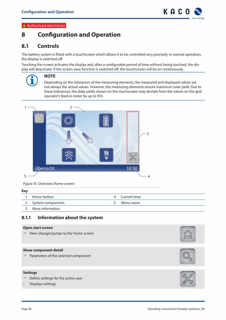
Configuration and Operation
Operating instructions Powador-gridsave_EN Page 31
Menu Submenu Display setting
Action in this menumeaning
Settings
Country amp directive display
Display of the country settings voltage directives and grid type
Select menu language
DateTime Specify time zone date format and date and time
Screen Activate screen-save function and set the delay period
Network settings
Display of the network settings Configure network settings Once the DHCP server becomes available the IP
address subnet mask gateway and DNS server are automatically applied and the aforemen-tioned menu items are hidden
Off DHCP deactivated make settings manually
Version Displays the installed software version and built-in HW components (inverter BBC battery)
Vendor The touchscreen shows information about the device vendor
NOTEAs changes to the software are possible after the manual has been printed the illustrations and descriptions of the functions in these operating instructions may deviate from the software Please therefore note the current Application Notes on our website
MaintenanceTroubleshooting
Page 32 Operating instructions Powador-gridsave_EN
9 MaintenanceTroubleshooting
91 Visual inspectionInspect the device and the cables for visible external damage and note the operating status display In case of damage notify your installer Repairs may only be carried out by authorised electricians
NOTEThe battery system should be checked for proper operation by a qualified electrician at regular intervals
92 Cleaning the device
DANGERLethal voltages in the battery systemSerious injuries or death can result if moisture enters the system rsaquo Only use completely dry objects to clean the battery system rsaquo Only clean the outside of the battery system
Cleaning the battery system Do not use compressed air Use a vacuum cleaner or a soft brush to remove dust from the fan cover and from the top of the inverter on a
regular basis Remove dust from the ventilation inlets if necessary
MaintenanceTroubleshooting
Operating instructions Powador-gridsave_EN Page 33
Authorised electrician
93 Maintenance
DANGERLethal voltages are still present in the terminals and cables in the device even after switching off and disconnection of the battery systemSevere injuries or death may occur if the cables and terminals in the device are touched The device is only permitted to be opened or serviced by an authorised electrician rsaquo Observe all safety regulations and the current technical connection specifications from the relevant
power supply company rsaquo Disconnect the AC and DC sides rsaquo Secure the AC and DC sides from being inadvertently switched back on rsaquo Only then should the device be opened rsaquo After shutdown wait at least 30 minutes before working on the device
CAUTIONDestruction of the DC connectionThe connection terminals can be destroyed by arcing if disconnected while still live rsaquo It is absolutely essential that the shutdown sequence be carried out in the correct order (See sec-
tion 111 on page 35)
94 Faults
941 Procedure
DANGERLethal voltages are still present in the terminals and cables in the device even after switching off and disconnection of the battery systemSevere injuries or death may occur if the cables and terminals in the device are touched
When a fault occurs notify an appropriately authorised and qualified electrician or KACO new energy GmbH Service
Service
Page 34 Operating instructions Powador-gridsave_EN
10 ServiceIf you need help solving a technical problem with one of our KACO products please contact our service hotline
Please have the following information ready so that we can help you quickly and efficientlybull Serial nobull SW version of the components (the software version can be found in the Settings menu using the EMS)bull Module type and string circuitbull Date of installation Start-up reportbull Consignment identification Delivery address Contact person (with telephone number)bull Information about the accessibility of the installation site
Any additional costs arising from unfavourable structural or mounting conditions shall be billed to the customer
You can find our warranty conditions on our websitehttpkaco-newenergycomservicewarrantyFrom there you can easily navigate to our international websites by clicking on the appropriate flag
Please use our website to register your unit immediatelyYou can also select the appropriate flag on this page to access the website for your own countryIn this manner you can assist us in providing you with the quickest service possible Note The maximum length of the warranty is based on the currently applicable national warranty conditions
We have prepared a template for complaints This can be found at httpskaco-newenergycomservicecustomer-service
Hotlines
Technical troubleshooting Technical consultation
Inverters and battery systems ()
+49 (0) 71323818-660 +49 (0) 71323818-660
Data logging and accessories +49 (0) 71323818-690 +49 (0) 71323818-690
Construction site emergency () +49 (0) 71323818-630
Customer help desk Monday to Friday from 730 am to 530 pm (CET)
() Also on Saturdays from 800 am to 200 pm (CET)
ShutdownDisassembly
Operating instructions Powador-gridsave_EN Page 35
11 ShutdownDisassembly
111 Switching off the device
DANGERLethal voltages are still present in the terminals and cables even after switching off and discon-nection of the battery systemSevere injuries or death may occur if the cables and terminals in the device are touched rsaquo Complete de-energisation only occurs if the bulk power supply is switched off upstream of the bat-
tery system
DANGERDestruction of the DC plug connectorDC plug connectors can be destroyed by arcing if disconnected while still live rsaquo It is absolutely essential that the following shutdown sequence is observed
1111 Step 1 Shutting down the PV system
1 Switch off any optional external PV isolator switches2 Set the internal DC isolator switch to OFF raquo The inverter and battery charging unit battery backup converter (BBC) are disconnected
1112 Step 2 Disconnect the batteries
NOTEPlease read the additional information in the enclosed manual Features for the battery unit
1113 Step 3 Disconnect the AC supply
1 Connect external isolation means to the device2 Switch off the circuit breaker 3 Switch off the residual current circuit breaker raquo The battery system is switched off
1114 Step 4 AC home power grid
1 Shutdown the AC home power grid using the AC main switch raquo The battery system can be uninstalled
Disposal
Page 36 Operating instructions Powador-gridsave_EN
112 Uninstalling the device
NOTETo uninstall follow the same sequence as for installation but in reverse order
Switch off the device1 Unlock and open the housing door2 Remove the upper cover3 Release the DC and AC cables from the connection terminals4 Pull out the cables raquo The battery system is uninstalled Continue with the disassembly
113 Disassembling the device
NOTETo disassemble follow the same sequence as for assembly but in reverse order
Switch off the device1 Uninstall the components2 Remove the fastening from the device3 Securely pack up the battery system if it is to be used later
or have the battery system disposed of in accordance with section 12 on page 36
12 DisposalFor the most part both the battery system and the corresponding transport packaging are made from recyclable raw materialsBatteries and components Do not dispose of faulty batteries or the components together with household waste Ensure that the old device and accessories are disposed of in a proper mannerPackaging Ensure that the transport packaging is disposed of properlyBatteriesUsed or faulty batteries must be transported in special packaging If you need such packaging please contact the KACO Hotline
NOTEPlease read the additional information in the enclosed manual Features for the battery unit
Appendix
Operating instructions Powador-gridsave_EN Page 37
13 Appendix
EU Declaration of Conformity
Vendorrsquos name and address
KACO new energy GmbH Carl-Zeiss-Straszlige 1 74172 Neckarsulm Germany
Product description Battery system
Type designation Powador-gridsave 135 kWh 6400 Powador-gridsave 135 kWh 8000
Powador-gridsave 270 kWh 6400 Powador-gridsave 270 kWh 8000
Powador-gridsave 405 kWh 6400 Powador-gridsave 405 kWh 8000
Powador-gridsave 540 kWh 6400 Powador-gridsave 540 kWh 8000
Powador-gridsave 577 kWh 6400 Powador-gridsave 577 kWh 8000
Powador-gridsave 675 kWh 6400 Powador-gridsave 675 kWh 8000
This is to confirm that the units listed above comply with the protection requirements set forth in the Directive of the Council of the European Union of 15th December 2004 on the harmonisation of the laws of the member states relating to Electromagnetic Compatibility (2004108EC) and the Low Voltage Directive (200695EC)The units are compliant with the following standards
200695EC ldquoDirective relating to electrical equipment designed for use within specific voltage limitsrdquo
Safety of the unitIEC 62109-12010IEC 62109-22011
2004108EC ldquoDirective relating to electromagneticcompatibilityrdquo
Interference immunityEN 61000-6-22005 Emitted interferenceEN 61000-6-32007
Secondary effects on the gridEN 61000-3-112000EN 61000-3-122005
The types mentioned above are therefore labelled with the CE markUnauthorised modifications to the supplied units andor any use of the units that is contrary to their intended use render this Declaration of Conformity null and void
Neckarsulm 0711 2013KACO new energy GmbH
pp Volker DietrichEnergy systems engineering management
Disposal
Page 38 Operating instructions Powador-gridsave_EN
Carl-Zeiss-Straszlige 1 middot 74172 Neckarsulm middot Germany middot Phone +49 7132 3818-0 middot Fax +49 7132 3818-703 middot infokaco-newenergyde middot wwwkaco-newenergyde
The
text
and
figu
res
refle
ct th
e cu
rren
t tec
hnic
al s
tate
at t
he ti
me
of p
rintin
g S
ubje
ct to
tech
nica
l cha
nges
Err
ors
and
omis
sion
s ex
cept
ed
3006
856-
01-1
4030
5
- 1General Information
-
- 11About this document
- 12Name plate
- 13Additional information
- 14Intended use
-
- 2Safety
-
- 21Protection features
-
- 3Description
-
- 31Mode of Operation
- 32Summary of the components
-
- 4Technical Data
-
- 41Electrical data
- 42Mechanical data
-
- 5Transportation and Delivery
-
- 51Delivery
- 52Storage
- 53Transportation
-
- 6Assembling the device
-
- 61Installation
- 62Installing components
-
- 7Installing the device
-
- 71Opening the connection area
- 72Making the electrical connection
- 73Connecting the interfaces
- 74Sealing the connection area
- 75Starting up
- 76Standard configuration
-
- 8Configuration and Operation
-
- 81Controls
-
- 9MaintenanceTroubleshooting
-
- 91Visual inspection
- 92Cleaning the device
- 93Maintenance
- 94Faults
-
- 10Service
- 11ShutdownDisassembly
-
- 111Switching off the device
- 112Uninstalling the device
- 113Disassembling the device
-
- 12Disposal
- 13Appendix
-
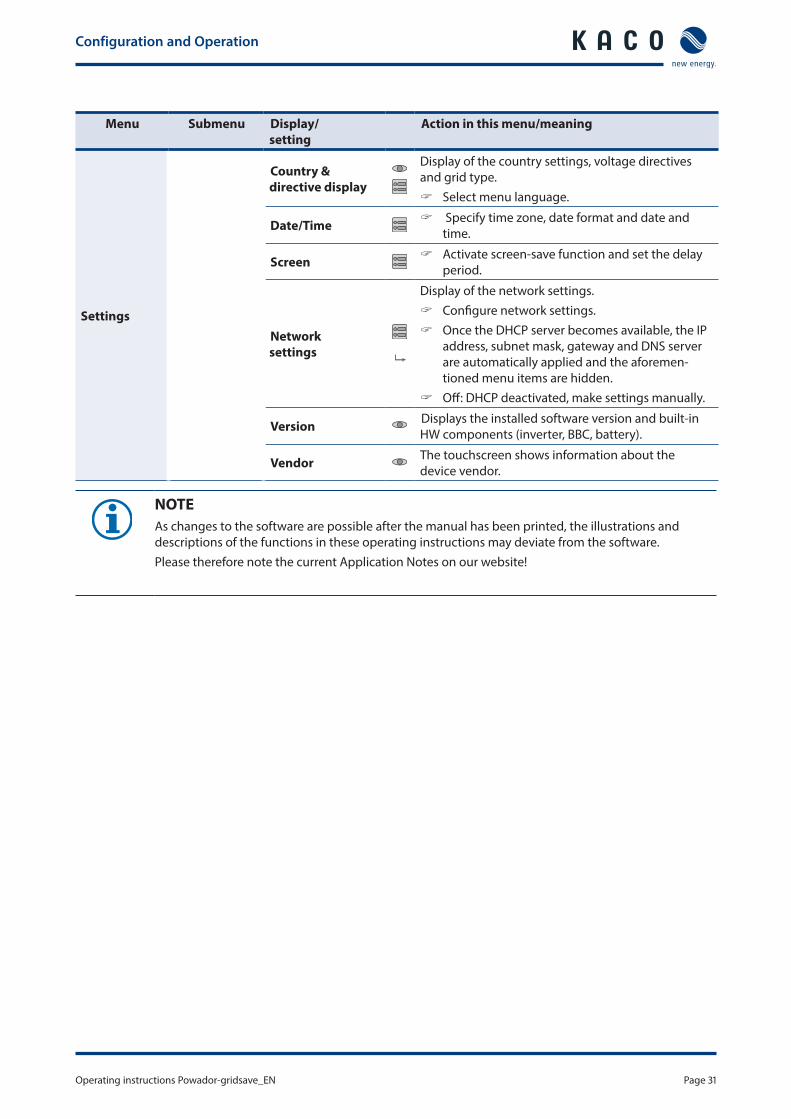
MaintenanceTroubleshooting
Operating instructions Powador-gridsave_EN Page 33
Authorised electrician
93 Maintenance
DANGERLethal voltages are still present in the terminals and cables in the device even after switching off and disconnection of the battery systemSevere injuries or death may occur if the cables and terminals in the device are touched The device is only permitted to be opened or serviced by an authorised electrician rsaquo Observe all safety regulations and the current technical connection specifications from the relevant
power supply company rsaquo Disconnect the AC and DC sides rsaquo Secure the AC and DC sides from being inadvertently switched back on rsaquo Only then should the device be opened rsaquo After shutdown wait at least 30 minutes before working on the device
CAUTIONDestruction of the DC connectionThe connection terminals can be destroyed by arcing if disconnected while still live rsaquo It is absolutely essential that the shutdown sequence be carried out in the correct order (See sec-
tion 111 on page 35)
94 Faults
941 Procedure
DANGERLethal voltages are still present in the terminals and cables in the device even after switching off and disconnection of the battery systemSevere injuries or death may occur if the cables and terminals in the device are touched
When a fault occurs notify an appropriately authorised and qualified electrician or KACO new energy GmbH Service
Service
Page 34 Operating instructions Powador-gridsave_EN
10 ServiceIf you need help solving a technical problem with one of our KACO products please contact our service hotline
Please have the following information ready so that we can help you quickly and efficientlybull Serial nobull SW version of the components (the software version can be found in the Settings menu using the EMS)bull Module type and string circuitbull Date of installation Start-up reportbull Consignment identification Delivery address Contact person (with telephone number)bull Information about the accessibility of the installation site
Any additional costs arising from unfavourable structural or mounting conditions shall be billed to the customer
You can find our warranty conditions on our websitehttpkaco-newenergycomservicewarrantyFrom there you can easily navigate to our international websites by clicking on the appropriate flag
Please use our website to register your unit immediatelyYou can also select the appropriate flag on this page to access the website for your own countryIn this manner you can assist us in providing you with the quickest service possible Note The maximum length of the warranty is based on the currently applicable national warranty conditions
We have prepared a template for complaints This can be found at httpskaco-newenergycomservicecustomer-service
Hotlines
Technical troubleshooting Technical consultation
Inverters and battery systems ()
+49 (0) 71323818-660 +49 (0) 71323818-660
Data logging and accessories +49 (0) 71323818-690 +49 (0) 71323818-690
Construction site emergency () +49 (0) 71323818-630
Customer help desk Monday to Friday from 730 am to 530 pm (CET)
() Also on Saturdays from 800 am to 200 pm (CET)
ShutdownDisassembly
Operating instructions Powador-gridsave_EN Page 35
11 ShutdownDisassembly
111 Switching off the device
DANGERLethal voltages are still present in the terminals and cables even after switching off and discon-nection of the battery systemSevere injuries or death may occur if the cables and terminals in the device are touched rsaquo Complete de-energisation only occurs if the bulk power supply is switched off upstream of the bat-
tery system
DANGERDestruction of the DC plug connectorDC plug connectors can be destroyed by arcing if disconnected while still live rsaquo It is absolutely essential that the following shutdown sequence is observed
1111 Step 1 Shutting down the PV system
1 Switch off any optional external PV isolator switches2 Set the internal DC isolator switch to OFF raquo The inverter and battery charging unit battery backup converter (BBC) are disconnected
1112 Step 2 Disconnect the batteries
NOTEPlease read the additional information in the enclosed manual Features for the battery unit
1113 Step 3 Disconnect the AC supply
1 Connect external isolation means to the device2 Switch off the circuit breaker 3 Switch off the residual current circuit breaker raquo The battery system is switched off
1114 Step 4 AC home power grid
1 Shutdown the AC home power grid using the AC main switch raquo The battery system can be uninstalled
Disposal
Page 36 Operating instructions Powador-gridsave_EN
112 Uninstalling the device
NOTETo uninstall follow the same sequence as for installation but in reverse order
Switch off the device1 Unlock and open the housing door2 Remove the upper cover3 Release the DC and AC cables from the connection terminals4 Pull out the cables raquo The battery system is uninstalled Continue with the disassembly
113 Disassembling the device
NOTETo disassemble follow the same sequence as for assembly but in reverse order
Switch off the device1 Uninstall the components2 Remove the fastening from the device3 Securely pack up the battery system if it is to be used later
or have the battery system disposed of in accordance with section 12 on page 36
12 DisposalFor the most part both the battery system and the corresponding transport packaging are made from recyclable raw materialsBatteries and components Do not dispose of faulty batteries or the components together with household waste Ensure that the old device and accessories are disposed of in a proper mannerPackaging Ensure that the transport packaging is disposed of properlyBatteriesUsed or faulty batteries must be transported in special packaging If you need such packaging please contact the KACO Hotline
NOTEPlease read the additional information in the enclosed manual Features for the battery unit
Appendix
Operating instructions Powador-gridsave_EN Page 37
13 Appendix
EU Declaration of Conformity
Vendorrsquos name and address
KACO new energy GmbH Carl-Zeiss-Straszlige 1 74172 Neckarsulm Germany
Product description Battery system
Type designation Powador-gridsave 135 kWh 6400 Powador-gridsave 135 kWh 8000
Powador-gridsave 270 kWh 6400 Powador-gridsave 270 kWh 8000
Powador-gridsave 405 kWh 6400 Powador-gridsave 405 kWh 8000
Powador-gridsave 540 kWh 6400 Powador-gridsave 540 kWh 8000
Powador-gridsave 577 kWh 6400 Powador-gridsave 577 kWh 8000
Powador-gridsave 675 kWh 6400 Powador-gridsave 675 kWh 8000
This is to confirm that the units listed above comply with the protection requirements set forth in the Directive of the Council of the European Union of 15th December 2004 on the harmonisation of the laws of the member states relating to Electromagnetic Compatibility (2004108EC) and the Low Voltage Directive (200695EC)The units are compliant with the following standards
200695EC ldquoDirective relating to electrical equipment designed for use within specific voltage limitsrdquo
Safety of the unitIEC 62109-12010IEC 62109-22011
2004108EC ldquoDirective relating to electromagneticcompatibilityrdquo
Interference immunityEN 61000-6-22005 Emitted interferenceEN 61000-6-32007
Secondary effects on the gridEN 61000-3-112000EN 61000-3-122005
The types mentioned above are therefore labelled with the CE markUnauthorised modifications to the supplied units andor any use of the units that is contrary to their intended use render this Declaration of Conformity null and void
Neckarsulm 0711 2013KACO new energy GmbH
pp Volker DietrichEnergy systems engineering management
Disposal
Page 38 Operating instructions Powador-gridsave_EN
Carl-Zeiss-Straszlige 1 middot 74172 Neckarsulm middot Germany middot Phone +49 7132 3818-0 middot Fax +49 7132 3818-703 middot infokaco-newenergyde middot wwwkaco-newenergyde
The
text
and
figu
res
refle
ct th
e cu
rren
t tec
hnic
al s
tate
at t
he ti
me
of p
rintin
g S
ubje
ct to
tech
nica
l cha
nges
Err
ors
and
omis
sion
s ex
cept
ed
3006
856-
01-1
4030
5
- 1General Information
-
- 11About this document
- 12Name plate
- 13Additional information
- 14Intended use
-
- 2Safety
-
- 21Protection features
-
- 3Description
-
- 31Mode of Operation
- 32Summary of the components
-
- 4Technical Data
-
- 41Electrical data
- 42Mechanical data
-
- 5Transportation and Delivery
-
- 51Delivery
- 52Storage
- 53Transportation
-
- 6Assembling the device
-
- 61Installation
- 62Installing components
-
- 7Installing the device
-
- 71Opening the connection area
- 72Making the electrical connection
- 73Connecting the interfaces
- 74Sealing the connection area
- 75Starting up
- 76Standard configuration
-
- 8Configuration and Operation
-
- 81Controls
-
- 9MaintenanceTroubleshooting
-
- 91Visual inspection
- 92Cleaning the device
- 93Maintenance
- 94Faults
-
- 10Service
- 11ShutdownDisassembly
-
- 111Switching off the device
- 112Uninstalling the device
- 113Disassembling the device
-
- 12Disposal
- 13Appendix
-

Disposal
Page 36 Operating instructions Powador-gridsave_EN
112 Uninstalling the device
NOTETo uninstall follow the same sequence as for installation but in reverse order
Switch off the device1 Unlock and open the housing door2 Remove the upper cover3 Release the DC and AC cables from the connection terminals4 Pull out the cables raquo The battery system is uninstalled Continue with the disassembly
113 Disassembling the device
NOTETo disassemble follow the same sequence as for assembly but in reverse order
Switch off the device1 Uninstall the components2 Remove the fastening from the device3 Securely pack up the battery system if it is to be used later
or have the battery system disposed of in accordance with section 12 on page 36
12 DisposalFor the most part both the battery system and the corresponding transport packaging are made from recyclable raw materialsBatteries and components Do not dispose of faulty batteries or the components together with household waste Ensure that the old device and accessories are disposed of in a proper mannerPackaging Ensure that the transport packaging is disposed of properlyBatteriesUsed or faulty batteries must be transported in special packaging If you need such packaging please contact the KACO Hotline
NOTEPlease read the additional information in the enclosed manual Features for the battery unit
Appendix
Operating instructions Powador-gridsave_EN Page 37
13 Appendix
EU Declaration of Conformity
Vendorrsquos name and address
KACO new energy GmbH Carl-Zeiss-Straszlige 1 74172 Neckarsulm Germany
Product description Battery system
Type designation Powador-gridsave 135 kWh 6400 Powador-gridsave 135 kWh 8000
Powador-gridsave 270 kWh 6400 Powador-gridsave 270 kWh 8000
Powador-gridsave 405 kWh 6400 Powador-gridsave 405 kWh 8000
Powador-gridsave 540 kWh 6400 Powador-gridsave 540 kWh 8000
Powador-gridsave 577 kWh 6400 Powador-gridsave 577 kWh 8000
Powador-gridsave 675 kWh 6400 Powador-gridsave 675 kWh 8000
This is to confirm that the units listed above comply with the protection requirements set forth in the Directive of the Council of the European Union of 15th December 2004 on the harmonisation of the laws of the member states relating to Electromagnetic Compatibility (2004108EC) and the Low Voltage Directive (200695EC)The units are compliant with the following standards
200695EC ldquoDirective relating to electrical equipment designed for use within specific voltage limitsrdquo
Safety of the unitIEC 62109-12010IEC 62109-22011
2004108EC ldquoDirective relating to electromagneticcompatibilityrdquo
Interference immunityEN 61000-6-22005 Emitted interferenceEN 61000-6-32007
Secondary effects on the gridEN 61000-3-112000EN 61000-3-122005
The types mentioned above are therefore labelled with the CE markUnauthorised modifications to the supplied units andor any use of the units that is contrary to their intended use render this Declaration of Conformity null and void
Neckarsulm 0711 2013KACO new energy GmbH
pp Volker DietrichEnergy systems engineering management
Disposal
Page 38 Operating instructions Powador-gridsave_EN
Carl-Zeiss-Straszlige 1 middot 74172 Neckarsulm middot Germany middot Phone +49 7132 3818-0 middot Fax +49 7132 3818-703 middot infokaco-newenergyde middot wwwkaco-newenergyde
The
text
and
figu
res
refle
ct th
e cu
rren
t tec
hnic
al s
tate
at t
he ti
me
of p
rintin
g S
ubje
ct to
tech
nica
l cha
nges
Err
ors
and
omis
sion
s ex
cept
ed
3006
856-
01-1
4030
5
- 1General Information
-
- 11About this document
- 12Name plate
- 13Additional information
- 14Intended use
-
- 2Safety
-
- 21Protection features
-
- 3Description
-
- 31Mode of Operation
- 32Summary of the components
-
- 4Technical Data
-
- 41Electrical data
- 42Mechanical data
-
- 5Transportation and Delivery
-
- 51Delivery
- 52Storage
- 53Transportation
-
- 6Assembling the device
-
- 61Installation
- 62Installing components
-
- 7Installing the device
-
- 71Opening the connection area
- 72Making the electrical connection
- 73Connecting the interfaces
- 74Sealing the connection area
- 75Starting up
- 76Standard configuration
-
- 8Configuration and Operation
-
- 81Controls
-
- 9MaintenanceTroubleshooting
-
- 91Visual inspection
- 92Cleaning the device
- 93Maintenance
- 94Faults
-
- 10Service
- 11ShutdownDisassembly
-
- 111Switching off the device
- 112Uninstalling the device
- 113Disassembling the device
-
- 12Disposal
- 13Appendix
-
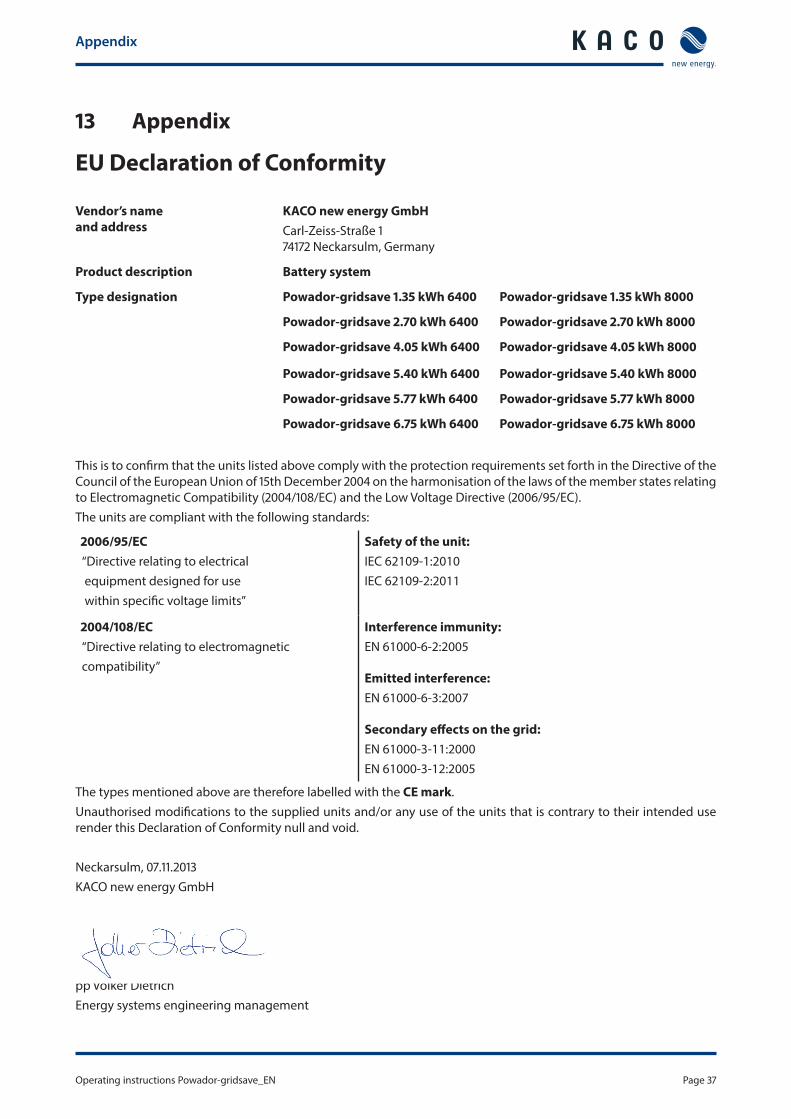