engineering manual for stanford townshipstanfordtownship.com/pages/pdfs/engineering manual.pdf ·...
TRANSCRIPT

ENGINEERING MANUAL FOR
STANFORD TOWNSHIP
Prepared by:
HAKANSON ANDERSON ASSOCIATES, INC. 3601 Thurston Avenue
Anoka, Minnesota 55303 Telephone: 763 - 427-5860
November 2009
Approval Date: November 2, 2009 Revision Date:

Forward
In order to protect the public health, safety and welfare, it is necessary to establish standards for engineering in the Township of Stanford, Isanti County, Minnesota.
This manual outlines specific requirements, materials and standards that will be incorporated into the preparation of plans and specifications for utility, street and other construction improvements within the Township.
Utility facilities and associated work shall be designed to conform to the "10 State Standards" and shall be constructed in accordance with City Engineers Association of Minnesota Standards Specifications except as modified by specific Township of Stanford requirements. Street surface improvements shall be designed to the standards of the Minnesota Department of Transportation design manuals and shall be constructed in accordance with the Minnesota Department of Transportation Standard Specifications except as modified by specific Township requirements.
Development plans and public facilities conskuction plans shall conform to Township of Stanford associated ordinances and comprehensive plans. Related to engineering, comprehensive plans include the surface water runoff control plan and the Township transportation plan with designated collector streets. The Township of Stanford has the authority to construct improvements as necessary with the costs of improvements allocated or assessed to properties for benefit.
Once the plat, plans and specifications and associated documents have been reviewed, approved and signed, the Township will allow the developers, as defined in the Development Agreement, to proceed with the construction.
These standards are established as policy and as such may be subject to change by action of the Town Board.
The Township of Stanford Engineering Manual was approved by the Town Board on November 2, 2009.
Joseph D. Pelawa, PE Township Engineer
III HAKANSON ANDERSON ASSOCIATES, INC.
3601 Thurston Avenue Anoka, MN 55303
Telephone: 763/427-5860
ii
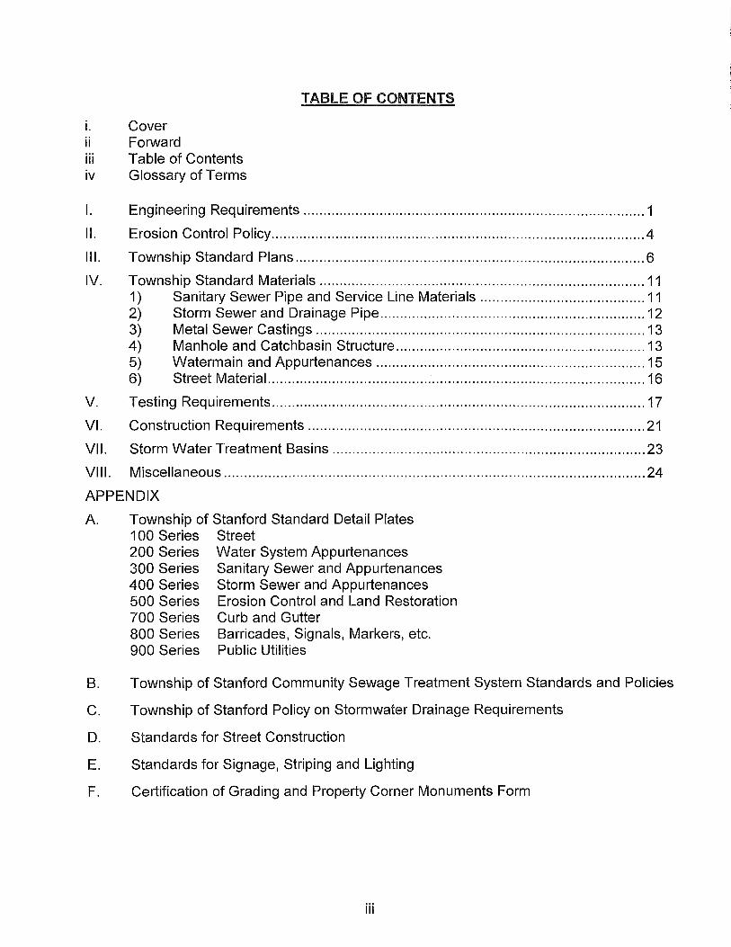
TABLE OF CONTENTS
i. Cover ii Forward iii Table of Contents iv Glossary of Terms
I. Engineering Requirements ..................................................................................... 1
II. Erosion Control Policy ............................................................................................. 4
III. Township Standard Plans ....................................................................................... 6
IV. Township Standard Materials ................................................................................. 11 1) Sanitary Sewer Pipe and Service Line Materials ......................................... 11 2) Storm Sewer and Drainage Pipe .................................................................. 12 3) Metal Sewer Castings .................................................................................. 13 4) Manhole and Catchbasin Structure .............................................................. 13 5) Watermain and Appurtenances ................................................................... 15 6) Street Material .............................................................................................. 16
V. Testing Requirements ............................................................................................. 17
VI. Construction Requirements .................................................................................... 21
VII. Storm Water Treatment Basins .............................................................................. 23
VIII. Miscellaneous ......................................................................................................... 24
APPENDIX
A. Township of Stanford Standard Detail Plates 1 00 Series Street 200 Series Water System Appurtenances 300 Series Sanitary Sewer and Appurtenances 400 Series Storm Sewer and Appurtenances 500 Series Erosion Control and Land Restoration 700 Series Curb and Gutter 800 Series Barricades, Signals, Markers, etc. 900 Series Public Utilities
B. Township of Stanford Community Sewage Treatment System Standards and Policies
C. Township of Stanford Policy on Stormwater Drainage Requirements
D. Standards for Street Construction
E. Standards for Signage, Striping and Lighting
F. Certification of Grading and Property Corner Monuments Form
iii
AASHTO
ANSI
ASTM
AWWA
CEAM
CMP
HOPE
Mn/DOT
MPCA
PID
PVC
RCP
SDR
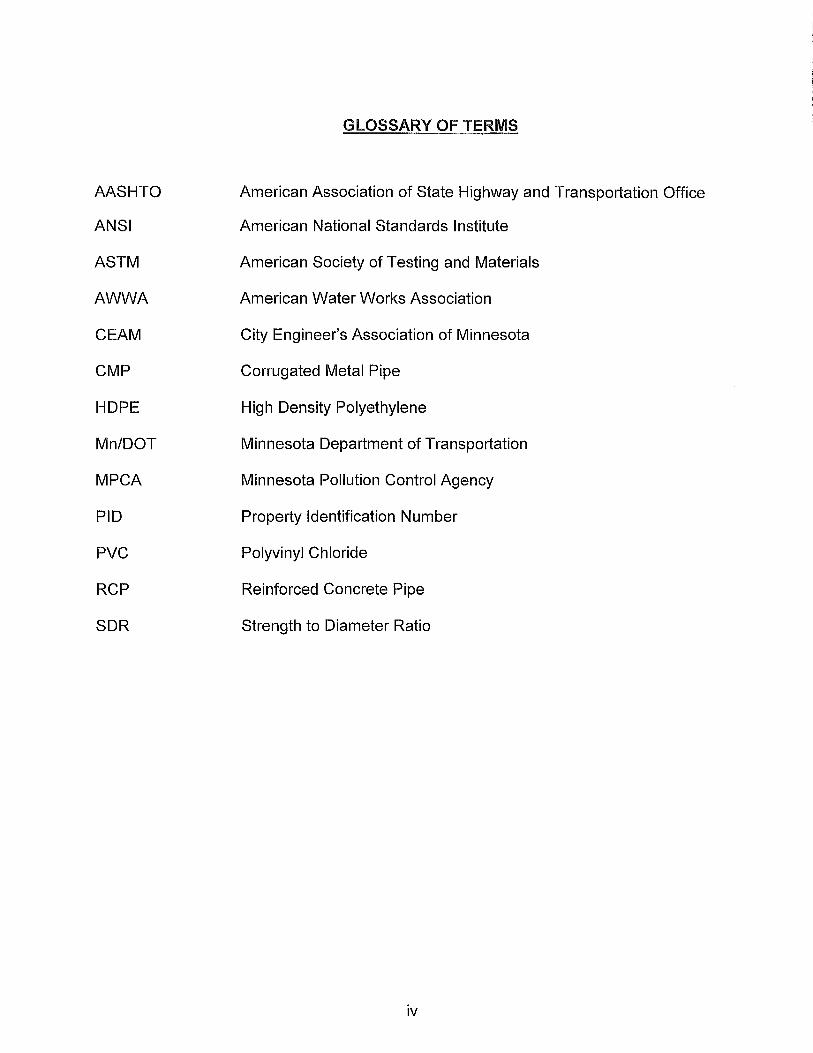
GLOSSARY OF TERMS
American Association of State Highway and Transportation Office
American National Standards Institute
American Society of Testing and Materials
American Water Works Association
City Engineer's Association of Minnesota
Corrugated Metal Pipe
High Density Polyethylene
Minnesota Department of Transportation
Minnesota Pollution Control Agency
Property Identification Number
Polyvinyl Chloride
Reinforced Concrete Pipe
Strength to Diameter Ratio
iv

ENGINEERING MANUAL
I. Engineering Requirements
As set forth in various sections of the Township ordinances, developers of property within the Township of Stanford are required to submit certain plans and specifications for review and approval by the Township. These include such items as grading plans, drainage plans, topographic surveys, plats, street and utility plans and specifications. These plans and specifications shall be prepared by competent professionals.
The professional services required of the Developer may include one or more of the following professionals: architect, land surveyor, planner, soils (geotechnical) and civil engineer and testing service. The engineering services include not only preparation of plans and specifications, but field staking in order to assure the Township that the completed project is in conformance with the approved plans and specifications. The Township will provide inspection of the installation of the facilities at the Developer's expense.
Within the development contract, the Developer has a choice in determining how the required improvements will be handled. The Developer can either construct and finance the improvements, or request that they be installed under a public improvement project and be assessed against the benefiting properties. Approval of the choice is a Town Board matter.
If the Developer chooses to install the required public improvements within the development, the following procedures shall be followed:
1 . The Developer shall submit plans, specifications and copies of all design calculations to the Township for review and approval. These plans are to be prepared by a licensed professional civil engineer and shall be in accordance with Township standards as outlined herein. The Developer's engineers shall submit errors and omissions insurance documentation prior to Township review. The Township guidelines shall be adhered to in design considerations. All sanitary sewer and watermain testing shall be completed and copies of service ties submitted to the Township prior to issuance of any service connection or building permits.
2. The Developer shall submit erosion and sediment control plans along with a Storm Water Pollution Prevention Plan to the Township for review and approval. No work is to begin until all erosion and sediment control methods are in place and approved by the Township.
3. The Developer shall furnish a separate Development Plan, which shows and lists house type, house pad front and back of pad elevations, garage floor
1

elevations, lowest opening elevation, lowest floor elevation, drainage arrows and street elevations in front of the driveway.
4. The Developer will be responsible for not only plans and specifications preparation, but also for providing staking. Resident inspection of said improvements to assure compliance with the approved plans shall be completed by the Township.
5. Copies of all bids, change orders, and other associated project costs documents relating to the improvements shall be forwarded to the Township Engineer.
6. The Developer shall furnish to the Township the list of selected contractors and subcontractors being considered for retention by the Developer for any of the public improvements work in the development. The Township has the right to reject any contractor or subcontractor deemed unacceptable to the Township.
7. Any changes to the approved plans and specifications shall be approved by the Township Engineer in writing before work is started. If the change affects the project letter of credit by increasing the cost, the letter of credit shall be increased before the work can begin.
8. The Developer will hold a preconstruction meeting at the Town Hall prior to start of any work on the development. The Township staff and Township Engineer along with the contractor and subcontractors, Developer's engineer, utility companies and other interested parties must be invited to the meeting. The Developer will be responsible for drafting pre-construction meeting minutes. The minutes shall be submitted to the Township Engineer for review, then distributed by the Developer to all parties who were in attendance at the meeting.
9. The Developer shall retain an independent testing service approved by the Town Board to perform the required material tests of the project. Copies of tests will be forwarded to the Township Engineerfor review. The cost of this service will be the responsibility of the Developer.
The Township shall be notified 24 hours in advance of all scheduled tests so its representatives can be present at the time tests are made. The required tests include utility installation, subgrade, base course, concrete placement, and bituminous pavement.
10. Upon completion of all the work required, the Township Engineer or his designated representative, a representative of the contractor and a representative of the Developer will make the required final inspections of all work. This includes a final inspection of all site grading, Class 5, concrete
2

curb or gravel shoulders, bituminous base placement and approval by the Township Engineer before any building permits will be issued. Before the final payment is made to the contractor by the Developer, the Township Engineer shall be satisfied that all work is satisfactorily completed in accordance with the approved plans and specifications, and the Developer's engineer shall submit a written statement attesting to same. Acceptance of the completed work shall be made by motion of the Town Board upon the recommendation of the Township Engineer. The warranty letter of credit security may be released, subject to the following:
a. The Developer or the Developer's engineer must submit written certification to the Township Engineer stating that all public improvements have been completed in accordance with the approved plans and specifications.
b. The Developer's engineer shall provide the Township with a complete set of Electronic files on computer disks and 2 sets of full size "asbuilt" plans for the Township records as outlined in this manual. These as-builts shall be submitted within 90 days after the completion of the improvements, and before any security is released.
c. The Developer's surveyor shall provide the Township with written certification that all corners of lots (iron monuments) have been placed.
11. An as-built survey signed by a Licensed Professional Land Surveyor for each individual lot will be required to verify lot corner elevations, swales, emergency overflow elevations, and house low floor and lowest opening elevations. Said survey shall be submitted to the Township for review and approved by the Township Engineer prior to the Certificate of Occupancy being issued.
12. Warranty Period - If within the time prescribed by law, by the contract documents and/or the Developer's Agreement any of the work is found to be unacceptable, the Developer shall correct it promptly unless the Township has previously accepted the work. The Developer shall give prompt notice after discovery of any unacceptable conditions to the contractor responsible for the project work.
Unless otherwise noted in the contract documents, the following requirements shall apply:
a. The Developer shall guarantee all work relating to utilities, appurtenances, material and equipment furnished by him for a period of two (2) years from the date of written acceptance of the work or project.
3

b. The Developer shall guarantee all work relating to street construction including concrete curb and gutter, sidewalks, materials and equipment furnished by hirn for a period of two (2) years from the date of written acceptance of the work or project. The streets will not be accepted prior to the bituminous wearing course being constructed.
c. The Developer shall provide a warranty letter of credit. The amount of the letter of credit will be determined by the Township Engineer based on 150% of the cost estimate of materials delivered to the project. The Developer shall include escrow funds as required by the Town Board for a portion of the letter of credit. The Developer will be required to deposit securities of the same amount and type within thirty (30) days of draws by the Township.
d. After all public improvements have been completed, properly inspected as specified above, and an acceptable maintenance guarantee provided, the project will be accepted by the Township and the Warranty Letter of Credit may be released.
II. Erosion Control Policy
1. Required Erosion Control Plan. Prior to commencing any earth disturbing activity in a development, the Developer shall prepare and submit an erosion control plan for approval by the Township Engineer. The plan shall be approved if it complies with Isanti County ordinance, the Township's Land Development Regulations, Road Ordinance, and the requirements contained herein. The Developer must also prepare and submit to the Township Engineer a Stormwater Pollution Prevention Plan (SWPPP) which meets the MPCA requirements.
2. Required Control Measures. The control measures shall conform to the MPCA's "Application for General Stormwater Permit for Construction Activity" (MN R1 00001) requirements and as specified herein;
a. The plan shall be suited to the topography and soils so as to create the least erosion potential.
b. The land shall be developed in increments of workable size on which adequate erosion and sediment controls can be provided and maintained during the construction period. Grading operations and other land disturbing operations shall be staged so that the area being developed is not exposed for long periods of time without stabilization.
c. Temporary vegetation and/or mulching shall be used to protect the
4

areas exposed during the development per the time frames as required by the permit.
d. Permanent vegetation and structures shall be installed per the time frames as required by the permit. If grading is not completed until after the planting season has expired, temporary erosion control measures, including dormant seeding and mulching, shall be implemented.
e. Sediment basins (debris basins, sediment basins, silt basins, or silt traps) shall be installed and maintained to remove sediment from runoff waters from the land undergoing development. Storm sewer inlets shall be provided with debris guards and silt basins to trap sediment and avoid possible damage from blockage. The sediment shall be removed when necessary to maintain effectiveness of control measure. If sediment/siltation measures taken are not adequate and result in downstream sediment pollution, the Developer shall be responsible for cleaning out or dredging downstream water conveyance systems, storm sewers and ponds as necessary.
f. Before grading is commenced, all control measures shall be installed as shown on the approved plan.
g. Immediately after curb and gutter has been placed, cured, and backfilled, or construction of the gravel shoulder, approved erosion control measures shall be installed directly behind the curb and shoulders.
h. Erosion control practices shall comply with the Minnesota Pollution Control Agency Best Management Practices.
i. The Developer shall be responsible for cleaning and maintenance of the storm sewer system (including ponds, infiltration basins, pipes, catch basins, culverts, and swales) within the development and the adjacent off-site storm sewer system that receives storm water from the development. The Developer shall follow all instructions it receives from the Township concerning the cleaning and maintenance of the storm sewer system. The Developer's obligations under this paragraph shall end two (2) years after the public improvements in the development have been accepted by the Township.
j. The Developer shall be responsible for cleaning all streets in the development and adjacent to the development from sediment and debris from the development for a period of two (2) years from when the streets have been completed and accepted by the Township.
5

k. A temporary concrete washout area is required. These temporary washout areas must not allow any liquid concrete, including rinse water from concrete-chutes and washing of concrete tools, to contact the bare ground. The waste material must be disposed of off-site in a MPCA-approved manner. A concrete washout sign must be installed at each temporary washout facility.
3. Financial Guarantee
a. A portion of the Developer's letter of credit required by the Developer's agreement shall include a guarantee of compliance with erosion control measures, and shall be furnished upon approval ofthe Developer's agreement before work is commenced. The financial guarantee shall remain in place until all the Developer's obligations under the erosion control plan have been satisfied.
b. If the Township draws upon the financial guarantee, the Developer shall within thirty (30) days of the draw, deposit with the Township additional security of the same type and amount that the Township has drawn. No further inspections will be conducted, no new building permits will be issued, and all work must stop within the development until the cash deposit for erosion control is restored to the pre-draw balance.
4. Street Sweepinq. The Developer shall provide street sweeping within the development before the final acceptance is approved. If the construction operations within or out of the development cause debris on the existing streets, the Township Engineer may require street sweeping done by the Developer.
5. Enforcement.
a. The Township or County may issue a stop work order halting all development work and building construction for noncompliance with the erosion control plan.
b. The Township may draw down the posted financial guarantee and perform any work necessary to achieve compliance with the erosion control plan. The Township will endeavor to give the Developer /Subdivider advance notice of such action.
III. Township Standard Plans
In order for the Township to have standardized construction and as-built plans, the guidelines listed below shall be followed:
6
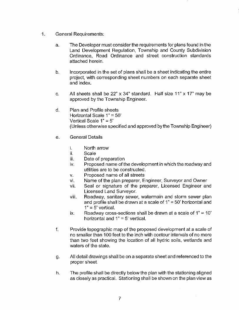
1. General Requirements:
a. The Developer must consider the requirements for plans found in the Land Development Regulation, Township and County Subdivision Ordinance, Road Ordinance and street construction standards attached herein.
b. Incorporated in the set of plans shall be a sheet indicating the entire project, with corresponding sheet numbers on each separate sheet and index.
c. All sheets shall be 22" x 34" standard. Half size 11" x 17" may be approved by the Township Engineer.
d. Plan and Profile sheets Horizontal Scale 1" = 50' Vertical Scale 1" = 5' (Unless otherwise specified and approved by the Township Engineer)
e. General Details
i. North arrow ii. Scale iii. Date of preparation iv. Proposed name of the development in which the roadway and
utilities are to be constructed. v. Proposed name of all streets vi. Name of the plan preparer, Engineer, Surveyor and Owner vii. Seal or signature of the preparer, Licensed Engineer and
Licensed Land Surveyor. viii. Roadway, sanitary sewer, watermain and storm sewer plan
and profile shall be drawn at a scale of 1" = 50' horizontal and 1" = 5' vertical.
ix. Roadway cross-sections shall be drawn at a scale of 1" = 1 0' horizontal and 1" = 5' vertical.
f. Provide topographic map of the proposed development at a scale of no smaller than 100 feet to the inch with contour intervals of no more than two feet showing the location of all hydric soils, wetlands and waters of the state.
g. All detail drawings shall be on a separate sheet and referenced to the proper sheet.
h. The profile shall be directly below the plan with the stationing aligned as closely as practical. Stationing shall be shown on the plan view as
7

well as the profile.
i. All parcels shall be properly labeled with lot and block numbers and plat name, or P.I.D. in unplatted areas. Developed parcels shall have their address shown on the plan. Bearings and distances for all existing roadway centerlines and right-of-ways described above shall be shown.
j. All matchline breaks shall be clean with reference points clearly marked. All plans which are broken by a matchline shall be on the same or consecutive sheets.
k. Existing utilities shall be shown in both plan and profile, stationed and labeled as existing.
I. Approximate locations of small utilities: gas, electric, telephone and cable lines shall be shown. Minnesota Statute requires locates.
m. Right of way and pavement or curb and gutter alignment data shall be shown.
n. Benchmarks shall be placed on all sheets. (N.G.V.D. 1929 Adj. datum)
o. All hydrants are to be at required height after lawns, boulevards, etc. are finished (sod, seed, etc.) This will be the Developer's responsibility.
2. Specific Requirements:
a. Stationing of sanitary sewer wyes shall be indicated "S" in front of the stationing. Sanitary sewer stationing is from the downstream manhole.
b. All sanitary sewer services shall be drawn on the plan to the constructed length and the length noted. Indicate if jacked.
c. If the sanitary sewer wye only is constructed, it shall be noted as "Wye Only" after stationing.
d. The invert elevation of all sanitary sewer services shall be shown on the plans. If risers are installed, the height of each shall be indicated on the plans and also drawn on the profile, along with the height of each riser.
e. All manholes shall be numbered on both plan and profile.
8

f. All hydrants, gate valves and tees shall be stationed on the bottom of the profile.
g. All water corporation stops shall be indicated by a "W" in front of its stationing.
h. All water services shall be drawn to constructed length and the length noted. Indicate if service is jacked.
i. The size and type of materials of all sanitary sewer and water services shall be noted on the plans.
j. On combination sewer and water projects, services may be placed in the same trench with sanitary sewer services three feet downstream from water services. Locations will be noted on the plans with an "s & W" in front of the stationing.
k. All sewer and watermain shall be shown in the profile with the appropriate information such as size, material, grades, invert elevations, etc.
I. All elevations shall be based on N.G.v.D. 1929 Adj. datum.
m. All hydrants and sanitary manholes (gravity and forcemain) within the water table shall be identified in the plans. The hydrants are to be marked with a metal strip, nozzle painted black and their drain holes are to be plugged.
n. Lots located in clay soils shall have draintile extended to, if they are more than one lot away from a storm sewer structure. The draintile is to serve as a means of promoting drainage along lot lines and as a connection point for home sump pump systems.
o. The plans shall depict a temporary concrete washout area. A sign must be placed at each temporary washout facility. A detail of the concrete washout area containment device is required.
3. As-Built Requirements:
a. All as-built plans shall be in an electronic acceptable format on computer disk with unnecessary construction information removed (trees, shrubs, fences, etc.). Two sets offull size as-built plans shall be provided in addition to the disks.
b. As-built plans on all ponding areas and drainage swales and ditches
9
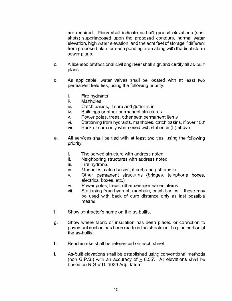
are required. Plans shall indicate as-built ground elevations (spot shots) superimposed upon the proposed contours, normal water elevation, high water elevation, and the acre feet of storage if different from proposed plan for each ponding area along with the final storm sewer plans.
c. A licensed professional civil engineer shall sign and certify all as-built plans.
d. As applicable, water valves shall be located with at least two permanent field ties, using the following priority:
i. Fire hydrants ii. Manholes iii. Catch basins, if curb and gutter is in iv. Buildings or other permanent structures v. Power poles, trees, other semipermanent items vi. Stationing from hydrants, manholes, catch basins, if over 100' vii. Back of curb only when used with station in (f.) above
e. All services shall be tied with at least two ties, using the following priority:
i. The served structure with address noted ii. Neighboring structures with address noted iii. Fire hydrants iv. Manholes, catch basins, if curb and gutter is in v. Other permanent structures (bridges, telephone boxes,
electrical boxes, etc.) vi. Power poles, trees, other semipermanent items vii. Stationing from hydrant, manhole, catch basins - these may
be used with back of curb distance only as last possible means.
f. Show contractor's name on the as-builts.
g. Show where fabric or insulation has been placed or correction to pavement section has been made in the streets on the plan portion of the as-builts.
h. Benchmarks shall be referenced on each sheet.
i. As-built elevations shall be established using conventional methods (non G.P.S.) with an accuracy of .± 0.05'. All elevations shall be based on N.G.v.D. 1929 Adj. datum.
10

j. The Community Septic Treatment System as-builts need to be provided prior to official Township start up.
IV. Township Standard Materials
In order to standardize certain construction materials and assure quality construction, we have adopted the following:
1. Sanitary Sewer Pipe and Service Line Materials
a. Plastic pipe shall be smooth wall polyvinyl chloride (PVC) and shall conform with ASTM D 3034 for the size and strength requirements shown on the plans. Minimum pipe strength shall be SDR 35. All joints shall be watertight elastomeric gasketed.
b. Ductile iron sewer pipe shall be minimum Class 50 and shall meet ANSI specifications A-21.51.
c. All connections between existing and new sanitary sewer and service pipe shall be made with factory manufactured flexible couplings, Fernco or equivalent, specially designed and sized for sanitary sewer connections as approved by the Engineer.
d. All PVC sanitary sewer service pipe and fittings, including PVC wyes, shall be SDR 26 minimum pipe strength.
e. Sanitary sewer forcemain and fittings shall be DIP class 50 or 52, or PVC (C900) pipe capable of withstanding pressure of 160 psi. Joints shall be watertight rubber gasketed as per ASTM F477.
f. Forcemain valves shall be plug and check valves as manufactures by Val-Matic, American Flow Control, Clow, Daigle Aqua, Mueller or an Engineer approved equal.
g. All forcemain air relieve valves shall be Val-Matic or an Engineer approved equal. A back flushing kit shall be supplied with each air valve.
h. Valve boxes shall be three piece adjustable screw type boxes, nominal 60" to 90" extension, with a 5 ~" shaft diameter. Valve boxes shall be provided with extension suitable forthe design location and a minimum 6-inch available adjustment after final setting. The word "Sanitary" shall be imprinted on each lid. All valve boxes must be true and plumb. Each valve box will be tested for plumbness using a section of 4" PVC pipe.
11
Valve box alignment device shall be Gate Valve Adaptor or Valve Box Adapter #6 base as manufactured by Adaptor Inc. or an Engineer approved equal. Gate Valve Adaptor for above water table installations and Valve Box Adapter #6 base for below water table installations.
All valves shall be fitted with extension stems to bring the operating nut to within l' from the surface.
2. Storm Sewer and Drainage Pipe
a. All storm sewer pipe within any street right-of-way (not including driveway culverts) shall be reinforced concrete pipe of the class as shown on the plans. Pipe shall meet Mn/DOT 3236 Specification. Joints shall be flexible watertight meeting ASTM C-361.
b. Storm sewer pipe on private property or on easements not used for vehicle traffic may be corrugated high density polyethylene (HDPE) pipe.
i. Corrugated high density polyethylene (HDPE) pipe and fittings shall meet the requirements of Mn/DOT specification 2503 (Corrugated Polyethylene Pipe Sewer).
c. Articulated Concrete Block, conforming to Mn/DOT 3604, is required at all storm sewer discharge pipes and pond overflows. Fabric blanket conforming to Mn/DOT 3733 (e.g. Mirafi 500 or 800) is required under the articulated block.
d. Erosion control (Wood fiber) blanket is required at all inlets. (See Mn/DOT Standard Plate No. 91 02D) All erosion control blanket shall be fastened to the ground using bio-degradable staples or wood stakes. Metal staples will not be allowed.
e. All flared end sections 24" and larger shall be fitted with trash guards.
f. Minimum size for storm sewer shall be 15" diameter, or equivalent. However, 12" diameter pipe will be allowed for catchbasin leads and on skimmer structure inlet pipes if necessary (to control discharge rate).
g. Draintile pipe shall be perforated Thermoplastic Pipe or Corrugated Polyethylene Drainage Tubing conforming to Mn/DOT 3245 or 3278 respectively, and shall be installed per Mn/DOT 2502 unless approved by City Engineer.
12
3. Metal Sewer Castings
a. Castings for sanitary sewer manholes shall be Neenah R-1733 or approved equal with a concealed pickhole and a neoprene gasket and groove for watertight application. The words "Sanitary Sewer" shall be imprinted on the cover. Waterproof castings where required shall be Neenah R-1751 or approved equal. Infi-shield shall be used to provide water tight exterior seal of sanitary sewer manhole rings and structure joints.
b. Castings for storm manholes and catch basins shall be in accordance with the standard plates and schedule of structures. Unless otherwise specified, castings shall be equivalent to Neenah R-1733 for manholes and R-3250-1 K for catch basins.
c. Castings for surmountable catch basin curb shall be Neenah R-3501 TRITL or equivalent. Yard inlet castings shall be Neenah R-4342 or equivalent.
4. Manhole and Catchbasin Structures
a. Manhole and catchbasin structures shall be in accordance with applicable Mn/DOT standard plates or standard plates as shown in the plans. All manholes and covers shall be reinforced for traffic loadings.
b. Manholes or catch basins identified on the plans as slab top shall be constructed from pipe manufactured to ASTM C-76 Standards, minimum Class 3 strengths.
c. Manholes identified on the plans as box structures shall be constructed from precast reinforced concrete box sections conforming to ASTM C-789 placed on end. Wall thickness and reinforcement shall be in accordance with ASTM C-789 Table 1 for box section under earth dead load and HS-25 live load conditions. Base and cover slabs shall have thickness and reinforcement to meet MnDOT HS-25 traffic loadings.
d. All manhole and catchbasin structures with builds greater than 4.0 feet from casting to invert shall have steps. Maximum distance from top of casting to first step is one and half (1 Yz) feet.
e. All manholes that are located in green areas shall be marked with a steel marker post and "MH" indicator sign. All manholes that are located within a gravel road shall be adjusted to l' below the surface and shall be marked with an offset steel marker post that is located
13

within the right-of-way.
f. Manhole Sealing
All sanitary sewer manholes (Gravity, Forcemain, Air-release, and Cleanout) shall be watertight. Joints below the water table shall be sealed.
i. The adjustment rings shall be sealed using either an Internal Chimney Seal as manufactured by Cretex Specialty Products or an Infi-Shield External Seal as manufactured by Sealing Systems, Inc. or approved equal. All seals shall be installed per the manufactures specifications.
1. Chimney Seal
a. The Chimney Seal shall consist of a flexible internal rubber sleeve, interlocking extension and stainless steel expansion bands with no welded attachments and a minimum adjustable range of 2 diameter inches. Any screws, bolts or nuts used shall be stainless steel. (See Standard Plate No. 308)
2. Infi-Shield (Preferred)
a. The Infi-Shield Seal shall consist of a continuous band( s) of high quality EPDM rubber and a nonhardening butyl mastic sealant. The casting shall be sealed to the structure with the external sealing system. The seal shall extend onto the casting and the cone section a minimum of 2".
II. All manhole joints within the water table shall be sealed using either an Internal Manhole Joint Seal as manufactured by Cretex Specialty Products or an External Infi-Shield Gator Wrap as manufactured by Sealing Systems, Inc. or approved equal. All new manholes shall use an external seal. All seals shall be installed per the manufactures specifications.
1. Internal Manhole Joint Seal (Existing Manholes)
a. The Internal Manhole Joint Seal shall consist of a flexible internal rubber sleeve, stainless steel restraining hoop, and stainless steel expansion
14

bands. For use on manhole joints subject to 14 ft of external water pressure head or less.
2. Externallnfi-Shield Gator Wrap (New Manholes)
a. The Infi-Shield Gator Wrap shall consist of an external EPDM flexible rubber sleeve and a nonhardening butyl mastic adhesive. For use on manhole joints subject to 30 ft of external water pressure head or less.
5. Watermain and Appurtenances
Materials shall conform to the Standard Specifications and to the following:
a. Watermain shall be mechanical joint ductile iron pipe conforming to AWWA Standards manufactured in the United States or Canada and shall be Class 52 with size as noted on the plans. All pipe shall be coated on the exterior and the interior shall be cement mortar lined. Joints shall conform to AWWA C111. Fittings shall be compact type conforming to AWWA C153.
b. As directed by the Township Engineer, "core blue" bolts shall be used in corrosive soil applications.
c. Bends shall be 45 degrees or less. Any deflection greater than 45 degrees shall be made with multiple bend sections with 12" pipe section between bends.
d. Valves 12" and larger shall be butterfly valves, AWWA C504, Mueller Line Seal or approved equal. Valves smaller than 12" in size shall be resilient wedge valves, Mueller A 2360 Series, Clow, Daigle Aqua Series 2500 or approved equal conforming to AWWA C509 standards. All valves shall be installed on-line with accompanying valve boxes. All valves shall close in a clockwise direction. All valves shall be epoxy coated as per AWWA C550.
Valve boxes shall be three piece adjustable screw type boxes, nominal 60" to 90" extension, with a 5 ~" shaft diameter. Valve boxes shall be provided with extension suitable forthe design location and a minimum 6-inch available adjustment after final setting. The word "Water" shall be imprinted on each lid. All valve boxes must be true and plumb. Each valve box will be tested for plumbness using a section of 4" PVC pipe.
15
All valves shall be fitted with extension stems to bring the operating nut to within l' from the surface. All valves located in green areas shall be marked with a steel marker post and "GV" sign. Marker post shall be offset 2'.
Valve box alignment device shall be Gate Valve Adaptor or Valve Box Adapter #6 base as manufactured by Adaptor Inc. or an Engineer approved equal. Gate Valve Adaptor for above water table installations and Valve Box Adapter #6 base for below water table installations.
e. Hydrants shall be Waterous Pacer WB 67 with a 5 ~" seat diameter. Hydrants shall have a traffic flange with 16" break off section. Hydrants shall have 2 each 2 1/2 " nozzles plus a pumper nozzle having nut caps with chains. A spring mounted 5'locator rod shall be attached to each hydrant.
f. All water service will be minimum 1" copper. All copper service pipes shall be Type K.
g. Corporation stops for 1" through 2" services shall be Mueller, A Y McDonald, or Ford FB Series Ballcorp. All services shall be wet tapped. Curb stops for 1" through 2" service shall be Ford Ball Valve B22 Series or Mueller Oriseal and shall be a Minneapolis pattern valve base with 2" inside diameter riser and a 2-inch western style cap with set screw with thread top. Curb box shall be Minneapolis base, sized to fit the curb stop. Boxes shall have a 1 ~" upper section and shall be furnished with a stationary rod 66" in length. Boxes shall have a minimum 12" adjustment to 8' when fully extended. All curb boxes located beneath driveways, shall have Ford Series A lid covers placed over the riser.
h. Water services larger than 2" shall be constructed with pipe, fittings, valves and boxes as specified for Ductile Iron Pipe installation.
i. Water meters shall be obtained and installed in accordance with Town Ordinances and development requirements.
6. Street Material
All materials shall be in conformance with Minnesota Department of Transportation Standard Specifications for Construction, 2005 edition and all subsequent revisions (Mn/DOT) or as modified herein in Appendix D.
a. All streets must be constructed and paved in accordance with Township Ordinances.
16

v. Testing Requirements
Materials shall be sampled and tested in accordance to the Mn/OOT Schedule of Material Control, except for as modified below. Utility systems shall be tested in accordance with the Standard Specifications forWatermain, Service Lines, Sanitary Sewer and Storm Sewer as published by the City Engineer's Association of Minnesota (CEAM). The Township Engineer shall be notified 24 hours in advance of the specific test.
1. Pipe Trench Compaction
a. Standard Proctor Density (ASTM 0-698-78): Proctor samples will be obtained within the utility trenches for each type of soil encountered in construction.
b. Density Test Nuclear (ASTM 0-2922): 1 test per lift of backfill, 1 test every 500 feet of pipe installed, minimum 1 test daily when backfilling.
c. Sand-Cone Method (ASTM 0-1556): The Township Engineer may order density tests by the sand cone method.
2. Embankment Compaction
a. Standard Proctor Density (ASTM 0-698-78): 1 test per source of material.
b. Density Test Nuclear (ASTM 0-2922): 1 test per lift of embankment, 1 test every 500 feet of roadway fill, 1 test daily when constructing embankment.
c. Density Test Sand-Cone Method (ASTM 0-1556): The Township Engineer may order density tests by the sand cone method.
3. Class 3 or 4 Aggregate
a. Standard Proctor Density (ASTM 0-698-78): 1 test per source of material.
b. Gradation Test: 1 test per source of material.
c. Density Test Nuclear (ASTM 0-2922): 1 test per lift of embankment, 1 test every 500 feet of roadway fill, 1 test daily when constructing embankment.
17
d. Density Test Sand-Cone method (ASTM D-1556): The Township Engineer may order density tests by the sand cone method.
4. Street Base Aggregate
a. Standard Proctor Density (ASTM D-698-78): 1 test per source of aggregate base, 1 test per 1000 tons of aggregate placed, 1 test daily when constructing base.
b. Gradation Test (ASTM D-422): 1 test per source of aggregate base, 1 test per 1000 tons of aggregate placed, 1 test daily when placing aggregate base.
c. Density Test (Nuclear ASTM D-2922): 1 test per 500 feet of roadway.
d. Test Rolling (MN/DOT 2111 ): Prior to placement of granular material, the Township requires the completion of a test roll on the street subgrade. The test roll shall conform to Mn/DOT 2111 except, the contractor shall provide a loaded tandem axle truck with a minimum nine (9) Ton axle load and gross weight of 25 tons. The contractor shall provide a weight ticket for the test roll vehicle to the Township Engineer during the test roll.
The test rolling shall be at the direction of the Township Engineer. A soils engineer and Township representative must be present during the test rolling and provide a written certification to the Township that the test passed or what corrections or recommendations are necessary if there is a failure.
The Township may also require test rolling of the aggregate base, once the base section has been constructed.
5. Bituminous Tests
a. General: Bituminous tests are to be conducted by an independent Mn/DOT certified testing laboratory. One core will be taken for every 500 tons placed, or a minimum of 3 cores per job. Bituminous cores shall be tested for in-place density and thickness.
b. Marshall Densities and Field Densities (ASTM D-1559): As required by Township Engineer.
c. Thickness: All cores shall be measured for in-place thickness.
18
6. Concrete Tests
a. General: When molding cylinders for strength tests, three cylinders are to be made according to ASTM C-31. One additional cylinder shall be molded when it is anticipated that surrounding air temperatures will fall below 40° Fahrenheit. Said cylinder shall be cured on site.
b. Compressive Strength (ASTM C-39): 1 set of 3 for every 1000 feet of curb and gutter constructed or 1 set of 3 for every 100 cubic yards of concrete placed or a minimum 1 set of 3 daily when pouring concrete.
c. Percent Air Test (ASTM C-231 ): 1 test for every 1000 feet of curb and gutter constructed or 1 test for every 100 cubic yards of concrete placed or a minimum 1 test daily when pouring concrete.
d. Slump Test (ASTM C-143): 1 test for every 1000 feet of curb and gutter constructed or 1 test for every 100 cubic yards of concrete placed or a minimum 1 test daily when pouring concrete.
7. Watermain Pressure Test (CEAM 2611.3. G)
a. Follows installation of all mainline pipe, services and hydrants, and pre-testing by Contractor.
b. Witnessed by Project Representative.
8. Electrical Conductivity Test (CEAM 2611.3.F)
a. Performed on all watermains within 7 days of satisfactory completion of the pressure test.
b. Witnessed by Project Representative.
c. Correction to any fire hydrants shall be made at the break off flange to avoid possible damage to internal parts.
9. Watermain Bacteriologic Quality Test (AWWA C-651)
a. Performed in the completed watermain after final flushing and before being placed in service.
b. Samples taken in presence of Project Representative.
19

10. Sanitary Sewer Air Test (CEAM 2621.F2)
a. Follows completion of all mainline pipe, service pipe and manhole installations.
b. Witnessed by Project Representative.
11. Sanitary Sewer Mandrel Test (CEAM 2521.G)
a. Follows completion of all mainline pipe installations by a minimum of 30 days.
b. Witnessed by Project Representative.
12. Televising of Sanitary Sewer
a. For pipes 8" diameter or larger, televising follows completion of all mainline pipes, service pipe and manhole installations.
b. Follows completion of flushing/clearing of system.
c. Witnessed by Project Representative.
d. A complete report (two copies) and a videotape or CD shall be submitted to the Township Engineer.
13. Sanitary Sewer Infiltration Test
a. All sanitary sewer pipes that are placed within the groundwater table must also be tested for infiltration.
b. Infiltration test limits shall be applied to single reaches of pipe (manhole to manhole) as applicable.
c. For pipes 8" through 15" in diameter, infiltration into the system (including manhole are not to exceed 50 gallons per mile of sewer pipe per inch of inside diameter per 24 hours. For all pipes larger than 15" in diameter, infiltration into the system (including manholes) shall not exceed 100 gallons per mile per inch of inside diameter of the sewer pipe per 24 hours. In no case shall the infiltration rate exceed 3,000 gallons per mile per 24 hours.
d. Infiltration tests shall be performed as a 4-day test and shall be monitored by the Project Representative.
20

14. Forcemain Pressure Test (CEAM 2611.3.G)
a. All foremain shall be subject to a hydrostatic pressure equal to twice the operating pressure, but no less than 100 psi.
b. Witnessed by Project Representative.
15. All PVC and plastic sewer or water pipes shall have tracer wire. Tracer wire shall be #10 AWG or#12 AWG copper insulated solid steel core with 30 mil HOPE insulation thickness and rated for underground service. Where horizontal directional drilling (HOD) is utilized to place these facilities two strands of tracer wire shall be pulled with the pipe. The tracer wire shall be connected to all metal fitting, valves, and fire hydrants. Where required tracer wire shall be brought to the surface in an control box (irrigation) and the locations shall be marked on the as-built drawings. Manufactured recommended crimps must be used when connecting two pieces of tracer wire.
VI. Construction Requirements
1. Sanitary Sewer, Watermain, and Storm Sewer
a. Applicable Specifications:
Work shall conform to the Standard Utility Specifications as published by the City Engineers Association of Minnesota, 1999 revision consisting of Part I - Standard Specifications for Watermain and Service Line Installation, Specification 2611; Part II - Standard Specifications for Sanitary Sewer and Storm Sewer Installation, Specifications 2621, except as herein modified.
b. Televising:
Televising shall be required for all gravity sanitary sewer pipe, joints and service connection. A tape or CD, and a report (two copies) shall be submitted to the Township Engineer.
2. Storm Sewer
Pipe sewers shall be installed in accordance with CEAM 2621 and Mn/DOT 2501, except as modified herein.
21

3. Casting Adjustments
All utility castings shall be adjusted as follows:
a. Sewer Manhole:
All sanitary and storm sewer manhole castings shall be in place during the laying of the wear course. The castings shall be adjusted before the mat is laid and shall be not less than 1/8" nor more than 1/4" below finished grade. Cast iron adjustment rings will be allowed to make the final adjustment prior to wear course paving. Paving must be completed within 48 hours of making the adjustment.
b. Storm Sewer:
Storm sewer inlet castings shall be adjusted so the flow line is 2" below finished gutter line.
c. Water Valve Boxes:
All water valve boxes shall be adjusted prior to wear course paving to 1/4" below finished grade. Only screw-type adjustments are allowed. All valve boxes must be constructed such that they are true and plumb. All valve boxes will be tested for plumbness using a alignment tube tool (section of 4" PVC pipe).
d. Grouting Adjusting Rings:
Whenever adjustment rings are provided, the contractor shall grout rings, place the castings and remove all excess grout on the inside and outside of the manhole by wiping smooth with a gloved hand or similar instrument.
4. Streets
Street construction shall be in accordance with Minnesota Department of Transportation Standard Specifications for Construction, 2005 edition and all subsequent revisions (Mn/DOT) including the following:
Common excavation and embankment - Mn/DOT 2105
Common excavation and embankment density or compaction requirements are as follows: Roadway embankment shall be compacted by the method described as "Specified Density" as outlined in Mn/DOT Section 2105.3 Paragraph F1.
22

Aggregate base - Mn/DOT 2211 with compaction by the specified density method.
Plant mixed bituminous non-wear - Mn/DOT 2350.
Tack coat - Mn/DOT 2357
Plant mixed bituminous wear - Mn/DOT 2350.
Concrete curbing - Mn/DOT 2531 using B618 or Standard Plate 700.
Concrete curing and protection - Mn/DOT 2531.3G
The street shall be constructed in accordance with typical sections shown on Township Standard Plates as outlined in Appendix A and detailed in Appendix D. The final wear course shall not be constructed until at least one winter freeze/thaw season after the bituminous base construction is completed.
Before excess common excavation, borrow or other materials from projects are deposited or mined on private property, a grading, fill or mining permit is required by the County/Township, plus permission in writing from the property owner.
5. Bituminous Tests:
a. General: Bituminous tests are to be conducted by an independent testing laboratory. One core will be taken for every 500 tons placed, or a minimum of 3 per job. Bituminous cores shall be tested for inplace density and thickness.
b. Rice Densities and Field Densities (ASTM D-1559)
c. Thickness: All cores shall be measured for in-place thickness.
VII. Storm Water Treatment Basins
1. Storm water conveyance, storage and treatment basins shall be designed in accordance with the Township of Stanford's policy on stormwater drainage as outlined in Appendix C. Typical basin construction and outlet structures are shown on the Township Standard Plates in Appendix A.
23
VIII. Miscellaneous
1. Proper notification of improvements shall be given by the Developer or his engineer to the responsible governmental agencies affected by said construction. All necessary permits shall be obtained prior to commencing any work. All special requirements of the responsible agencies shall be complied with.
2. The Developer's contractor shall furnish, erect and maintain signs and barricades as provided in Mn/DOT 1710 "Barricades and Signs" to protect the public. The Township Engineer shall be notified 24 hours prior to the proposed partial blockage or closure of any street or public right-of-way. No street or public right-of-way shall be closed without the proper approval of the Township Engineer and appropriate agencies and emergency departments.
3. It is the responsibility of the Developer's contractor to protect and leave undisturbed those markers or monuments set for the subdivision of land.
4. The Developer and/or his contractor shall immediately repair or replace at his own expense any defective workmanship or material of which he is notified during the construction period, or within the warranty period following the date of final acceptance of the work, regardless of the approval and acceptance of the work.
5. A plan forthe routing (Detour) of construction traffic shall be submitted to the Township Engineer for his approval. Roads (County, Township) that are utilized for access or egress to the construction site shall be kept free of unsuitable dirt and other debris resulting from said construction. Adequate dust control shall be maintained by the Developer's contractor.
6. The Township will require the contractor to submit a list of materials and respective suppliers as well as all tests of materials.
7. If any material or labor supplied by the contractor or Developer is rejected by the Township Engineer or his designated representative as defective or unsuitable, then such rejected material shall be promptly removed, disposed of off the job site, and replaced with approved material.
8. All street right-of-ways shall be cleared and grubbed to full width except as specifically directed.
9. Any utility and drainage easements adjacent to the street right-of-way shall be cleared and grubbed for the placement of utilities except as specifically directed.
24

10. Work shall not commence before 7:00 a.m. nor extend beyond 7:00 p.m. Monday through Friday. On Saturdays, the hours will be from 8:00 a.m. to 6:00 p.m. No work is to be done on Sundays. Hours and days of work may be modified based on need and approved by Township Engineer.
11. Mailboxes shall be located in clusters in all new urban subdivisions. The locations of the mailbox cluster areas shall be shown on the plan. The location and side of the street that the clusters are located on shall be determined by the local mail carrier/United States Postal office.
12. Driveway grades shall be no greater than 8%.
25