end-pumped monoblock laser for eyesafe … · traditional lenses, (shannon 1991, verdún 1992, turi...
TRANSCRIPT
END-PUMPED MONOBLOCK LASER FOR EYESAFE TARGETING SYSTEMS
Bradley W. Schilling*, Stephen Chinn, A. D. Hays, Lew Goldberg, C. Ward Trussell
US ARMY RDECOM CERDEC
Night Vision and Electronic Sensors Directorate (NVESD)
Ft. Belvoir, VA 22060
ABSTRACT
We describe a next-generation monoblock laser capable
of greater than 10 mJ, 1.5 µm output at 10 pulses per
second (PPS) over broad ambient temperature extremes
with no active temperature control. The transmitter
design is based on a Nd:YAG laser with a Cr4+ passive
Q-switch and intracavity KTP OPO. In order to achieve
the repetition rate and efficiency goals of this effort, but
still have wide temperature capability, we are end-
pumping the Nd:YAG slab with a 12-bar stack of 100 W
(each) diode bars. We compare different techniques for
focusing the pump radiation into the 4.25 mm x 4.25 mm
end of the slab, including a lensed design, a reflective
concentrator, and a lens-duct. We demonstrate wide-
temperature operation (-20 to 50 degrees Celsius) for
each end-pumped configuration.
1.0 INTRODUCTION
Laser technology to reduce the cost, size, and weight of
laser-based military systems is critical to the Army’s
highly mobile force. Laser targeting applications for
Army Future Combat System (FCS) and Future Force
Warrior (FFW) include eyesafe laser rangefinding, laser
illumination for gated 2D imaging and 3D laser radar
systems. These systems require high peak-power laser
sources in the eyesafe wavelength band, with pulse
energies near 10 mJ, and pulse durations less then 20 ns.
Central to this class of laser we continue to develop an
enabling technology coined the “monoblock laser” due to
its one-piece nature and simplicity of manufacture
(Nettleton, 2000). Variations of this laser have been used
in several prototype and limited production systems,
including the STORM multi-function laser system, and
as an illumination laser for a short wave infrared (SWIR)
gated-imaging system (Vollmerhausen, 2003). Recently,
we have been experimenting with technology to improve
the repetition-rate and efficiency of the monoblock laser.
Improvements in these parameters directly effect the
speed at which FCS/FFW targeting operations can occur
and system power consumption (which equates to battery
life for many hand-held systems), respectively.
The first generation monoblock laser
assemblies employ a flashlamp-pumped architecture
based on cost considerations, the robust and mature
nature of the technology, and its ability to function well
over a broad range of temperatures. However, flashlamps
are very broadband sources, producing radiation over
many hundreds of nanometers (nm) from the UV to
infrared wavelengths. As Figure 2 shows, the targeted
absorption of Nd:YAG is strongest in narrow bands
between 790 nm and 825 nm. The majority of emitted
flashlamp energy, therefore, does not contribute to
population inversion in the gain material, but generates
unwanted heat, reducing the laser’s repetition rate
capability and efficiency. A common alternative to lamp-
pumped solid state lasers is to optically pump the gain
material directly with semiconductor diode lasers. As the
dotted trace in Figure 2 shows, a typical pump-diode
operates with a comparatively narrow optical bandwidth.
Diode-pump sources are selected that overlap the
absorption region of the gain material, virtually
eliminating out-of-band pump radiation that produces
heat. Unfortunately, there is a drawback to diode-
pumping solid-state lasers: the diode wavelength changes
significantly with temperature. Over a 70 degree Celsius
(C) temperature span, the center wavelength will shift by
as much as 30 nm. In practice, pump-diodes are often
temperature controlled to ensure that the diode
wavelength remains on an absorption peak of the gain
medium as the ambient temperature drifts or the diodes
heat up. Devices used to control diode temperature, such
as TE coolers, add system complexity, can be costly and
consume relatively large amounts of power. For these
reasons, it is desirable to develop diode-pumped solid-
state lasers without active temperature control for
applications where size, weight, and power consumption
are important, such as military-qualified laser systems.
Due to the limited absorption length inherent in side-
pumped configurations, these designs are particularly
susceptible to these shifting wavelength issues. The
difficulties encountered with side-diode-pumped laser
operation over large temperature extremes are discussed
and demonstrated experimentally in this paper.
More consistent output over temperature
extremes can be obtained with an end-pumped
configuration due to its longer absorption length, if the

Report Documentation Page Form ApprovedOMB No. 0704-0188
Public reporting burden for the collection of information is estimated to average 1 hour per response, including the time for reviewing instructions, searching existing data sources, gathering andmaintaining the data needed, and completing and reviewing the collection of information. Send comments regarding this burden estimate or any other aspect of this collection of information,including suggestions for reducing this burden, to Washington Headquarters Services, Directorate for Information Operations and Reports, 1215 Jefferson Davis Highway, Suite 1204, ArlingtonVA 22202-4302. Respondents should be aware that notwithstanding any other provision of law, no person shall be subject to a penalty for failing to comply with a collection of information if itdoes not display a currently valid OMB control number.
1. REPORT DATE 01 NOV 2006
2. REPORT TYPE N/A
3. DATES COVERED -
4. TITLE AND SUBTITLE End-Pumped Monoblock Laser For Eyesafe Targeting Systems
5a. CONTRACT NUMBER
5b. GRANT NUMBER
5c. PROGRAM ELEMENT NUMBER
6. AUTHOR(S) 5d. PROJECT NUMBER
5e. TASK NUMBER
5f. WORK UNIT NUMBER
7. PERFORMING ORGANIZATION NAME(S) AND ADDRESS(ES) US ARMY RDECOM CERDEC Night Vision and Electronic SensorsDirectorate (NVESD) Ft. Belvoir, VA 22060
8. PERFORMING ORGANIZATIONREPORT NUMBER
9. SPONSORING/MONITORING AGENCY NAME(S) AND ADDRESS(ES) 10. SPONSOR/MONITOR’S ACRONYM(S)
11. SPONSOR/MONITOR’S REPORT NUMBER(S)
12. DISTRIBUTION/AVAILABILITY STATEMENT Approved for public release, distribution unlimited
13. SUPPLEMENTARY NOTES See also ADM002075., The original document contains color images.
14. ABSTRACT
15. SUBJECT TERMS
16. SECURITY CLASSIFICATION OF: 17. LIMITATION OF ABSTRACT
UU
18. NUMBEROF PAGES
29
19a. NAME OFRESPONSIBLE PERSON
a. REPORT unclassified
b. ABSTRACT unclassified
c. THIS PAGE unclassified
Standard Form 298 (Rev. 8-98) Prescribed by ANSI Std Z39-18

difficulties associated with efficient optical coupling can
be overcome. Numerous end-pumping techniques have
been reported in the literature, including the use of
traditional lenses, (Shannon 1991, Verdún 1992, Turi
1995, Snyder 1991) reflective devices, (Liao 1997,
Clarkson 1996) lens ducts, (Beach 1996, Fu 1998)11-13
and other coupling devices.14 After a thorough survey of
these techniques, we selected a few candidates for further
testing based on their suitability for pumping the
monoblock laser, including the expected impact on
overall size, ruggedness, manufacturability, and cost of a
laser system. We decided to experiment with end-
pumping designs based on microlenses and lens ducts
due to the expected high efficiency, (Beach 1996) and
with reflective concentrators based on their simplicity.
Each end-pumping configuration is described in detail,
and its performance measured over temperatures from -
20°C to 50°C.
2. LASER DESIGN
2.1 Diode pumping over temperature
Claims concerning the advantages of end-pumping solid-
state lasers are numerous, including better extraction
efficiency, (Moulton, 1991) better mode quality, (Fu
1998) and improved frequency stabilization (Zhou,
1985). Our primary interest in end-pumping the
monoblock laser is the advantage in performance over
wide temperature extremes. An important issue for
military-qualified diode-pumped laser systems results
from the inherent change in diode wavelength with
temperature, typically 0.2 – 0.4 nm per °C. This means
that over a 70 degree temperature range, the diode
wavelength will drift as much as 30 nm. This is an issue
because the absorption properties of Nd:YAG have a
strong dependence on wavelength. The absorption
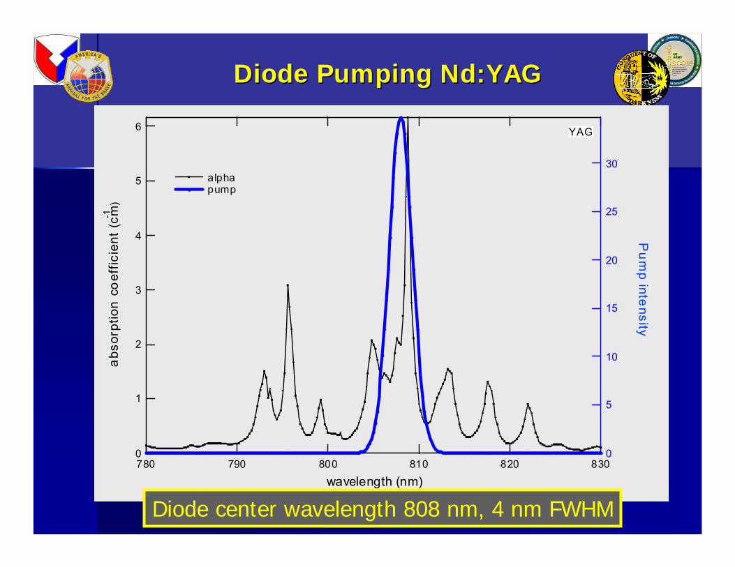
coefficient, α(λ), for 1% doped, bulk Nd:YAG is plotted
for a 25 nm span near 800 nm in Figure 1. Pump
radiation is absorbed in the laser gain material in
accordance with Beer’s law: ( ) ( )0
xI x I e
α λ−= where I0
is the initial optical intensity and I(x) is the optical
intensity at position x in the gain medium.
Making use of Beer’s law and the measured
absorption coefficient data for Nd:YAG given in Figure
1, the necessary absorption length to absorb 60%, 70%,
80%, and 90% of the pump radiation in Nd:YAG is
shown in Figure 2. From this simple analysis we see that
for pump wavelengths near 808 nm, the radiation will be
easily absorbed even for very short absorption lengths.
On the other hand, as the wavelength of the pump light
drifts, due to temperature changes, 30 mm of gain
material (or more) may be required to absorb even 60%
of the pump light. A dashed line in Figure 2 indicates an
absorption length of 8.5 mm, which is the double pass
length available for side pumping a 4.25 mm gain slab.
Given the requirement of military qualified lasers to
operate over wide temperature extremes, and the need for
compact and low-power-consumption laser systems (no
active temperature control), we see the advantage that an
end-pumped configuration has over side-pumping
because of the much longer absorption length.
Experimental verification of the problems side-diode-
pumped Nd:YAG lasers have over temperature extremes
is given in section 3 below.
6
5
4
3
2
1
0
absorption coefficient (cm
-1 )
830820810800790780
wavelength (nm)
30
25
20
15
10
5
0
Pump intensity
alpha pump
YAG
Fig. 1 – Absorption coefficient of 1% doped Nd:YAG vs.
wavelength
6
5
4
3
2
1
0
absorption length [cm]
815810805800795790
wavelength [nm]
% Absorption 90% 80% 70% 60%
Figure 2 – Beer’s Law for Nd:YAG show absorption
length required to absorb N% of pump radiation at
different wavengths for N = 60, 70, 80, 90
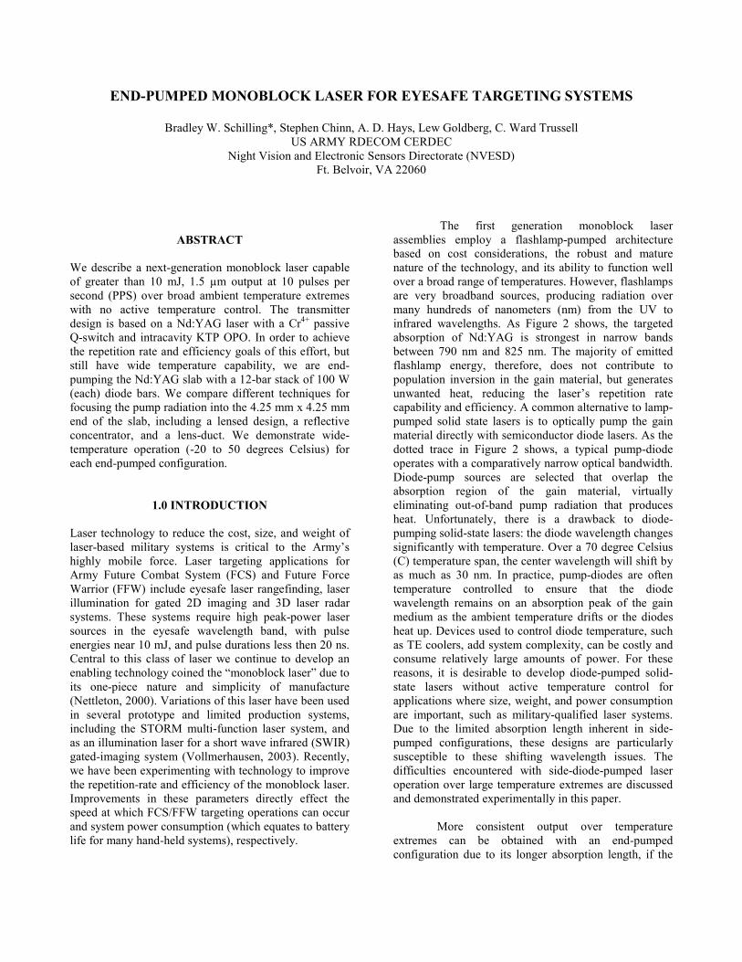
2.2 Monoblock Laser
A block diagram of the monoblock laser transmitter
design is shown in Figure 3 and a photograph of a
monoblock laser manufactured by Scientific Materials
Corporation (SMC) is shown in Figure 4. The gain
medium is a square Nd:YAG laser rod having 1%
neodymium doping with a 4.25 mm x 4.25 mm cross-
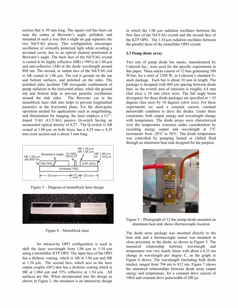
section that is 30 mm long. The square rod has been cut
near the center at Brewster’s angle, polished, and
mounted in such a way that a slight air gap separates the
two Nd:YAG pieces. This configuration encourages
oscillation of vertically polarized light while avoiding a
deviated cavity due to an optical element positioned at
Brewster’s angle. The back face of the Nd:YAG crystal
is coated to be highly reflective (HR) (>99%) at 1.06 µm
and anti-reflective (AR) at the diode wavelength around
808 nm. The second, or output face of the Nd:YAG rod
is AR coated at 1.06 µm. The rod is ground on the top
and bottom surfaces, and polished on the sides. The
polished sides facilitate TIR waveguide confinement of
pump radiation in the horizontal plane, while the ground
top and bottom help to prevent parasitic oscillations
around the slab sides. The Brewster cut in the
monoblock laser slab also helps to prevent longitudinal
parasitics in the horizontal plane. For the short-pulse
operation needed for applications such as rangefinding,
and illumination for imaging, the laser employs a Cr4+-
doped YAG (Cr:YAG) passive Q-switch having an
unsaturated optical density of 0.27. The Q-switch is AR
coated at 1.06 µm on both faces, has a 4.25 mm x 4.25
mm cross section and is about 3 mm long.
Cr:YAGOD=0.27
Nd:YAG KTP OPO
HR 1.06 mAR 808 nm
µ
HR 1.54 mAR 1.06 m
µµ
HR 1.06 mOC 1.54 m
µµ
Brewster's angle
30 mm 20 mm10 mm
Undoped YAG
Figure 3 – Diagram of monoblock laser design
Figure 4 – Monoblock laser
An intracavity OPO configuration is used to
shift the laser wavelength from 1.06 µm to 1.54 µm
using a monolithic KTP OPO. The input face of the OPO
has a dichroic coating, which is AR at 1.06 µm and HR
at 1.54 µm. The second face, which acts as the laser
output coupler (OC) also has a dichroic coating which is
HR at 1.064 µm and 55% reflective at 1.54 µm. All
surfaces are flat. When incorporated into the design as
shown in Figure 3, the resonator is an intracavity design
in which the 1.06 µm radiation oscillates between the
first face of the Nd:YAG crystal and the second face of
the KTP OPO. The 1.54 µm radiation oscillates between
the parallel faces of the monolithic OPO crystal.
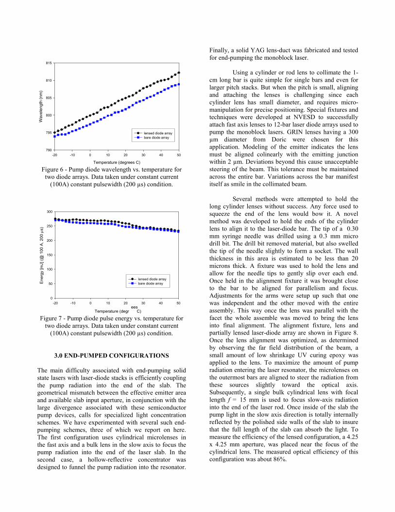
2.3 Pump diode array
Two sets of pump diode bar stacks, manufactured by
Coherent Inc., were used for the specific experiments in
this paper. These stacks consist of 12 bars generating 100
W/bar, for a total of 1200 W, in Coherent’s standard G-
stack package. Each bar is about 10 mm in length. The
package is designed with 400 µm spacing between diode
bars, so the overall area of emission is roughly 4.8 mm
(fast axis) x 10 mm (slow axis). The full angle beam
divergence for these diode packages are specified at < 35
degrees (fast axis) by 10 degrees (slow axis). For these
experiments we used a constant current, constant
pulsewidth condition to drive the diodes. Under these
constraints, both output energy and wavelength change
with temperature. The diode arrays were characterized
over the temperature extremes under consideration by
recording energy output and wavelength at 2°C
increments from -20°C to 50°C. The diode temperature
was controlled by pumping heated or chilled fluid
through an aluminum heat sink designed for the purpose.
Figure 5 – Photograph of 12-bar pump-diode mounted on
aluminum heat sink shows thermocouple location
The diode array package was mounted directly to the
heat sink and a thermocouple sensor was mounted in
close proximity to the diode, as shown in Figure 5. The
measured relationship between wavelength and
temperature was very nearly linear with about a 0.25 nm
change in wavelength per degree C, as the graph in
Figure 6 shows. The wavelength (including both diode
stacks), ranged from 794 nm to 812 nm. Figure 7 shows
the measured relationships between diode array output
energy and temperature, for a constant drive current of
100A and constant drive pulsewidth of 200 µs.
Temperature (degrees C)
-20 -10 0 10 20 30 40 50
Wavelength (nm)
790
795
800
805
810
815
lensed diode array
bare diode array
Figure 6 - Pump diode wavelength vs. temperature for
two diode arrays. Data taken under constant current
(100A) constant pulsewidth (200 µs) condition.
Temperature (degre e s
C)
-20 -10 0 10 20 30 40 50
Energy [mJ] (@
100 A, 200 µs)
0
50
100
150
200
250
300
lensed diode array
bare diode array
Figure 7 - Pump diode pulse energy vs. temperature for
two diode arrays. Data taken under constant current
(100A) constant pulsewidth (200 µs) condition.
3.0 END-PUMPED CONFIGURATIONS
The main difficulty associated with end-pumping solid
state lasers with laser-diode stacks is efficiently coupling
the pump radiation into the end of the slab. The
geometrical mismatch between the effective emitter area
and available slab input aperture, in conjunction with the
large divergence associated with these semiconductor
pump devices, calls for specialized light concentration
schemes. We have experimented with several such end-
pumping schemes, three of which we report on here.
The first configuration uses cylindrical microlenses in
the fast axis and a bulk lens in the slow axis to focus the
pump radiation into the end of the laser slab. In the
second case, a hollow-reflective concentrator was
designed to funnel the pump radiation into the resonator.
Finally, a solid YAG lens-duct was fabricated and tested
for end-pumping the monoblock laser.
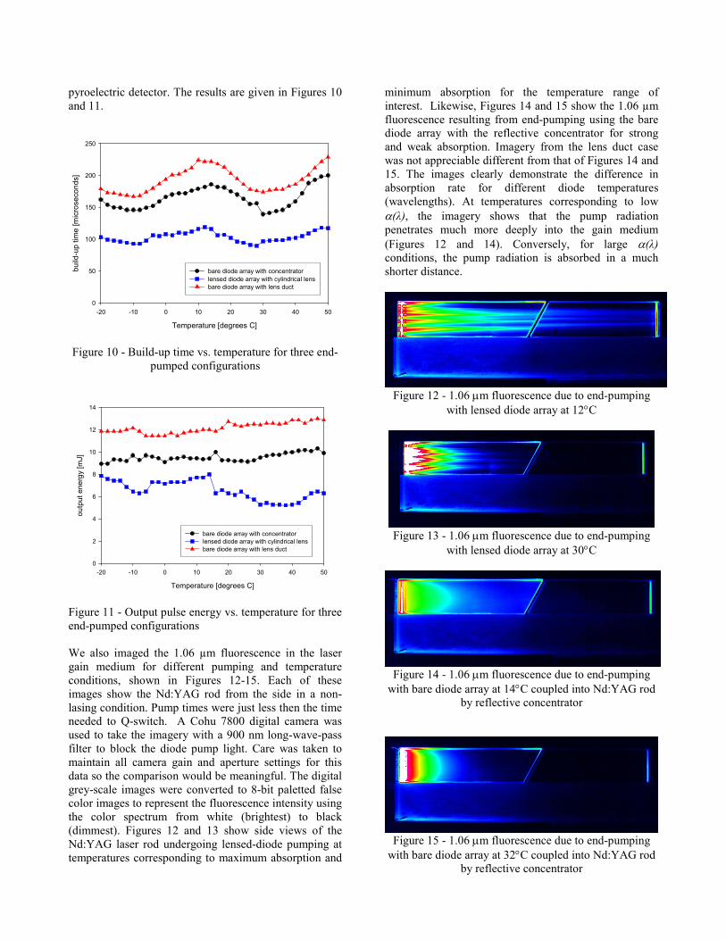
Using a cylinder or rod lens to collimate the 1-
cm long bar is quite simple for single bars and even for
larger pitch stacks. But when the pitch is small, aligning
and attaching the lenses is challenging since each
cylinder lens has small diameter, and requires micro-
manipulation for precise positioning. Special fixtures and
techniques were developed at NVESD to successfully
attach fast axis lenses to 12-bar laser diode arrays used to
pump the monoblock lasers. GRIN lenses having a 300
µm diameter from Doric were chosen for this
application. Modeling of the emitter indicates the lens
must be aligned colinearly with the emitting junction
within 2 µm. Deviations beyond this cause unacceptable
steering of the beam. This tolerance must be maintained
across the entire bar. Variations across the bar manifest
itself as smile in the collimated beam.
Several methods were attempted to hold the
long cylinder lenses without success. Any force used to
squeeze the end of the lens would bow it. A novel
method was developed to hold the ends of the cylinder
lens to align it to the laser-diode bar. The tip of a 0.30
mm syringe needle was drilled using a 0.3 mm micro
drill bit. The drill bit removed material, but also swelled
the tip of the needle slightly to form a socket. The wall
thickness in this area is estimated to be less than 20
microns thick. A fixture was used to hold the lens and
allow for the needle tips to gently slip over each end.
Once held in the alignment fixture it was brought close
to the bar to be aligned for parallelism and focus.
Adjustments for the arms were setup up such that one
was independent and the other moved with the entire
assembly. This way once the lens was parallel with the
facet the whole assemble was moved to bring the lens
into final alignment. The alignment fixture, lens and
partially lensed laser-diode array are shown in Figure 8.
Once the lens alignment was optimized, as determined
by observing the far field distribution of the beam, a
small amount of low shrinkage UV curing epoxy was
applied to the lens. To maximize the amount of pump
radiation entering the laser resonator, the microlenses on
the outermost bars are aligned to steer the radiation from
these sources slightly toward the optical axis.
Subsequently, a single bulk cylindrical lens with focal
length f = 15 mm is used to focus slow-axis radiation
into the end of the laser rod. Once inside of the slab the
pump light in the slow axis direction is totally internally
reflected by the polished side walls of the slab to insure
that the full length of the slab can absorb the light. To
measure the efficiency of the lensed configuration, a 4.25
x 4.25 mm aperture, was placed near the focus of the
cylindrical lens. The measured optical efficiency of this
configuration was about 86%.

Figure 8 – Drawing of the alignment fixture, lens being
aligned and partially lensed laser-diode array
We decided to experiment with the second
approach, a hollow-reflective concentrator, due to its
simplicity. We fashioned a rectangular “light funnel”
from thin (< 1 mm) gold coated mirrors. The launch end
of the concentrator is designed to be slightly larger than
the diode stack emitting area, approximately 11 mm x 5
mm, while the output end is slightly smaller than the
input aperture of the square laser rod, 4.25 mm x 4.25
mm. Determination of the optimum concentrator length
involves trading-off small length with concentrator pitch
angle. For steep angles the pump light leaves the
concentrator with higher divergence, resulting in reduced
coupling efficiency. For very steep pitch angles, the
radiation can actually reflect back on itself, never leaving
the concentrator. Optical ray trace models were used to
aid in selecting the optimal concentrator length, of 24
mm. The measured optical efficiency of this reflective
concentrator is about 83%.
The third configuration for end-pumping uses a
lens duct having the same nominal dimensions as the
concentrator discussed above. The lens duct is fabricated
from undoped YAG, polished on all sides, and AR
coated for the nominal pump wavelength (centered at
808nm) on the entrance and exit surfaces. A lens duct is
simple to fabricate and align, like the reflective
concentrator, but with better efficiency. When compared
to the reflective concentrator, the lens duct is a somewhat
more expensive option due to materials cost and optical
coating, but is still relatively inexpensive compared to
other laser components. The lens duct has a measured
optical efficiency of about 90%.
4.0 EXPERIMENTAL RESULTS
To verify the difficulties associated with side-pumping
solid-state lasers over large temperature extremes, we
arranged the monoblock laser described in section 2.2 in
a side-pumped configuration. We used the bare diode
array, described in section 2.3 with the output end placed
in close proximity to the side of the gain medium of the
monoblock laser. A reflector was placed on the opposite
side of the Nd:YAG slab to enable a double-pass
absorption path 8.5 mm in length. The diode temperature
was taken from -20°C to 50°C, and the 1.5 µm
monoblock pulse energy was measured at 2° intervals.
The results are plotted in Figure 9, with energy vs.
temperature axes on the right and top. As Figure 9
indicates, the laser did not reach threshold for diode
temperatures that resulted in pump wavelengths
corresponding to low α(λ) in Nd:YAG. To emphasize
this point, we plotted on the same graph, the percentage
of pump radiation that is absorbed in 8.5 mm of bulk
Nd:YAG in accordance with Beer’s law, given by: I(x)/I0
= e-α(λ)x
for x = 8.5 mm. These results indicate that for
this case, absorption of somewhere around 80% of the
pump light is required to reach the Q-switch threshold.
For the side-pumped configuration, this requirement
could not be met with 8.5 mm of absorption length for all
operating temperatures. This experiment demonstrates
why side-pumped schemes are not ideal for military-
qualified laser systems that must operate over large
temperature bandwidths with size and power constraints
that eliminate the possibility of active temperature
control.
pump wavelength [nm]
794 796 798 800 802 804 806 808 810
percent of energy absorbed
0
20
40
60
80
100
Diode Temperature [degrees C]
-20 -10 0 10 20 30 40 50
Side-pumped output energy [mJ]
1
2
3
4
5
6
7
percent absorption for 8.5 mm
output energy
Figure 9 – Output energy vs. temperature (right and top
axes) for side pumped configuration along with percent
energy absorbed vs. diode wavelength (left and bottom
axes) in 8.5 mm of bulk Nd:YAG according to Beer’s
law
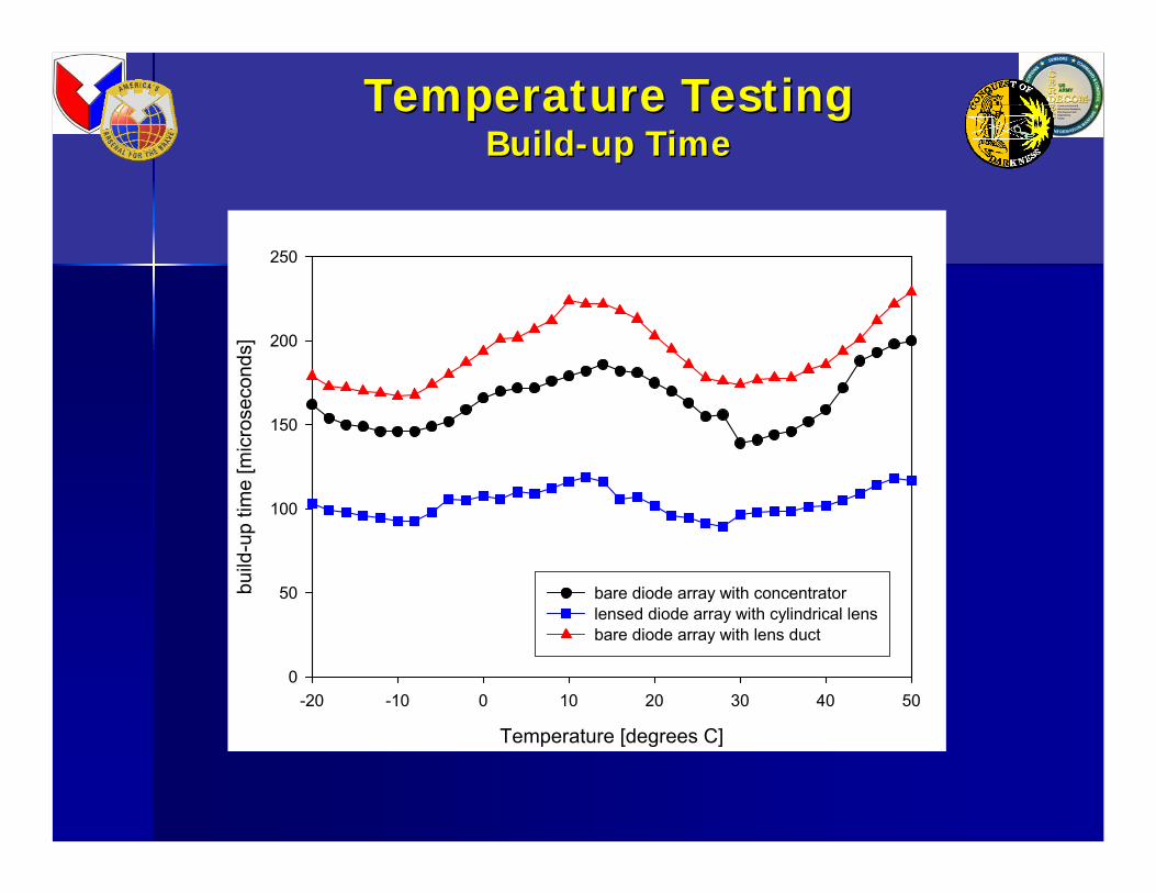
Next, each of the end-pump configurations
described in section 3 was applied to the monoblock
laser using the diode stacks characterized in section 2.3.
For each end-pumped configuration, the monoblock laser
was operated continuously at a 10 Hz repetition rate. The
diode temperature was taken from -20°C to 50°C as
described above. For every 2°C change in temperature,
the Q-switch build-up time and the pulse energy of the
1.5 µm OPO output were recorded. Build-up time was
measured with a Tektronix TDS 3054B oscilloscope, and
pulse energy was measured with an Ophir PE50
pyroelectric detector. The results are given in Figures 10
and 11.
Temperature [degrees C]
-20 -10 0 10 20 30 40 50
build-up time [microseconds]
0
50
100
150
200
250
bare diode array with concentrator
lensed diode array with cylindrical lens
bare diode array with lens duct
Figure 10 - Build-up time vs. temperature for three end-
pumped configurations
Temperature [degrees C]
-20 -10 0 10 20 30 40 50
output energy [mJ]
0
2
4
6
8
10
12
14
bare diode array with concentrator
lensed diode array with cylindrical lens
bare diode array with lens duct
Figure 11 - Output pulse energy vs. temperature for three
end-pumped configurations
We also imaged the 1.06 µm fluorescence in the laser
gain medium for different pumping and temperature
conditions, shown in Figures 12-15. Each of these
images show the Nd:YAG rod from the side in a non-
lasing condition. Pump times were just less then the time
needed to Q-switch. A Cohu 7800 digital camera was
used to take the imagery with a 900 nm long-wave-pass
filter to block the diode pump light. Care was taken to
maintain all camera gain and aperture settings for this
data so the comparison would be meaningful. The digital
grey-scale images were converted to 8-bit paletted false
color images to represent the fluorescence intensity using
the color spectrum from white (brightest) to black
(dimmest). Figures 12 and 13 show side views of the
Nd:YAG laser rod undergoing lensed-diode pumping at
temperatures corresponding to maximum absorption and
minimum absorption for the temperature range of
interest. Likewise, Figures 14 and 15 show the 1.06 µm
fluorescence resulting from end-pumping using the bare
diode array with the reflective concentrator for strong
and weak absorption. Imagery from the lens duct case
was not appreciable different from that of Figures 14 and
15. The images clearly demonstrate the difference in
absorption rate for different diode temperatures
(wavelengths). At temperatures corresponding to low
α(λ), the imagery shows that the pump radiation
penetrates much more deeply into the gain medium
(Figures 12 and 14). Conversely, for large α(λ) conditions, the pump radiation is absorbed in a much
shorter distance.
Figure 12 - 1.06 µm fluorescence due to end-pumping
with lensed diode array at 12°C
Figure 13 - 1.06 µm fluorescence due to end-pumping
with lensed diode array at 30°C
Figure 14 - 1.06 µm fluorescence due to end-pumping
with bare diode array at 14°C coupled into Nd:YAG rod by reflective concentrator
Figure 15 - 1.06 µm fluorescence due to end-pumping
with bare diode array at 32°C coupled into Nd:YAG rod by reflective concentrator

5.0 DISCUSSION
As the data shows, each end-pumped
configuration operated at a 10 PPS repetition rate over
the entire 70°C temperature range with output pulses in
the 10 mJ regime. In contrast, when the same laser was
side-pumped, lasing only occurred at temperatures
corresponding to favorable absorption lengths. From a
manufacturing perspective, it was our experience that
physically lensing the diode-arrays is difficult, requires
special fixturing, and is labor intensive. The
concentrator-type devices are easy to align and relatively
inexpensive, with the reflective concentrator being the
most cost effective. As far as optical throughput is
concerned, the lensed configuration and the lens duct
have very similar throughput (about 90%), while the
reflective device was somewhat less efficient.
From the perspective of 1.5 µm laser output, the
lens duct case produced the highest output pulse energy
over the entire temperature span, with minimum and
maximum pulse energies of 11.4 mJ and 13.0 mJ,
respectively. This configuration also had the longest
build-up times associated with it, approaching 250 µsec
for temperatures associated with weak absorption in the
slab. The lensed case operated with consistently shorter
build-up times and correspondingly lower output energy,
more like 5 to 8 mJ. The reflective concentrator pump
configuration, performed somewhere in-between the
other two cases.
At first glance, the large variation in output
energies for the different configurations is somewhat
surprising, given that the same passively Q-switched
laser is used in each case. We expected to measure
relatively consistent output energies for each case,
resulting from a consistent level of fluence in the
resonator needed to bleach the passive Q-switch, with a
difference in buildup times corresponding to the optical
efficiencies of each pumping scheme. However, the
lensed case consistently produced lower energy pulses,
about 50-60% that of the pulse energy for the lens duct.
We explain the apparent inconsistency as being due
primarily to the spatial characteristics of the pump
intensity profile. As the imagery included as Figures 12-
15 shows, the pump beam profile for the lensed case has
a significant amount of cross-sectional structure,
manifested as individual beams radiating down the slab.
In contrast, the concentrator seems to homogenize the
pump light intensity distribution, making it relatively
uniform across the crystal. The highly nonuniform
structure in the pump beam is undesirable, particularly
for passively Q-switched devices since “hotspots” in the
pump profile may lead to localized regions of higher gain
and spatially selective bleaching of the Cr:YAG. Such
localized bleaching of the Q-switch will result in lower
pulse energy since the full cross section of the resonator
may not be contributing to laser action. A
correspondingly shorter build-up time is also consistent
with local bleaching at hot spots since the Q-switch
won’t hold-off as long as for the case where pump
intensity distribution is uniform. The more uniform
pump distribution of the concentrator and lens duct
results in larger pulse energies and longer hold-off.
Temperature [degrees C]
-20 -10 0 10 20 30 40 50
optical-to-optical efficiency
0.00
0.01
0.02
0.03
0.04
0.05
0.06
0.07
bare diode array with concentrator
lensed diode array with cylindrical lens
bare diode array with lens duct
Figure 16 - Optical to optical efficiency vs. temperature
for three end-pumped configurations
Finally, we want to investigate the overall
optical-to-optical efficiency of the laser, ηo, defined as the ratio of diode-pump energy to 1.5 µm output pulse
energy. We calculate the pulse energy needed to achieve
Q-switching as:
∆=200
tEE dp , (1)
where Ep is the pump pulse energy, ∆t is the buildup time
in µs, and Ed is the measured diode pulse energy for a
200 µs long drive current (given in Figure 7.) Optical
efficiency is then given by, poo EE=η , where Eo is
the output pulse energy at 1.5 µm. This efficiency,
plotted in Figure 16 as a function of temperature, appears
to be similar for all pumping configurations, varying
between 4% and 6%. Again, the YAG lens duct still has
the best overall performance with regard to optical
efficiency, but here the reflective concentrator performs
the worst, consistent with its low pump throughput
efficiency. For comparison we note that the flashlamp-
pumped monoblock laser has optical-to-optical
efficiency about an order of magnitude lower.
6.0 CONCLUSIONS
In this paper, we address the needs for an eyesafe laser
transmitter operating in the 10 millijoule regime at tens

of Hz repetition rate with optical to optical efficiency
near 5%. We have described the next generation
monoblock laser, a low-cost, compact, and rugged
transmitter designed to meet the stringent requirements
of military laser systems with application to eyesafe
rangefinding and other targeting scenarios. The
transmitter design is based on a Nd:YAG laser with a
Cr4+ passive Q-switch and an intracavity KTP OPO. In
order to achieve the repetition rate and efficiency goals
of this effort, we experimented with end-pumped
versions of the monoblock laser. Our impetus for end-
diode-pumping is the improved performance over broad
temperature ranges without active heating or cooling.
Fundamental to this issue is the change in pump-diode
wavelength with temperature and strong wavelength
dependence of the absorption coefficient for Nd:YAG.
We have shown that the impact of these effects can be
mitigated by the long absorption lengths available in
end-pumped configurations. We investigated several
end-pumping schemes with application to the monoblock
laser, each demonstrating higher wall-plug efficiency and
repetition rate capability than previous flashlamp-
pumped designs. We compared the configurations over a
70°C temperature span from -20°C to 50°C. Each of the
tested end-pump configurations gave complete operation
over the full temperature range. Although we measured a
high pumping efficiency from configuration I, we found
the lensed diode array emits a pump beam that contains
significant cross-sectional structure. We suspect, based
on low overall output energy and short build-up time,
this highly structured pump beam leads to partial
bleaching of the Q-switch at localized areas of high
fluence. We got the best overall performance (ηo = 4-6%) from a pump scheme based on a YAG lens duct,
which is easy to manufacture and align. The simple bare
diode and concentrator scheme still performed quite well
(ηo ~ 4.0%) and may have a cost advantage over the lens
duct based on material and optical coating
considerations. Although not reported on here, we have
found that using a lensed diode array in conjunction with
a concentrator or lens duct gives a slight improvement
over the efficiencies reported here. The funnel-style
devices act to homogenize the pump beam while the
lensed diodes give the ducts better overall throughput. In
our opinion, however, the improvement does not justify
the added expense of lensing the diodes for a production-
class device.
ACKNOWLEDGMENTS
The authors acknowledge the support received from the
Penn State Electro-Optics Center, with special thanks to
David Snyder and Jason Carter for lending their
technical as well as programmatic expertise to this effort.
We would also like to thank John Nettleton and Dallas
Barr of NVESD for the many helpful ideas and
discussions surrounding the monoblock laser work.
Thanks also to Jeff Leach of NVESD for help with the
temperature experiments.
REFERENCES
Beach, R. J., “Theory and Optimization of lens ducts,”
Appl. Opt. 35, 2005-2015 (1996).
Clarkson, W. A., and Hanna, D. C., “Efficient Nd:YAG
laser end pumped by a 20-W diode-laser bar” Opt.
Lett. 21, 869-871 (1996).
Fu, R. et al., “Design of efficient lens ducts.” Appl. Opt.
37, 4000-4003 (1998).
Liao, Y. et al., “Highly efficient diode-stack, end-
pumped Nd:YAG slab laser with symmetrized beam
quality,” Appl. Opt. 36, 20 (1997).
Moulton, P.F., “Pumping with diodes,” IEEE Circuits
and Devices Magazine 7, 36-40 (1991).
Nettleton, J. E., Schilling, B. W., Barr, D. N. and Lei, J.
S., “Monoblock laser for a low-cost, eyesafe,
microlaser range finder,” Appl. Opt. 39, 2428-2432,
(2000).
Shannon, D. C. and Wallace, R. W., ‘‘High-power
Nd:YAG laser end pumped by a cw, 10 mm 3 1 µm
aperture, 10-W laser-diode bar,’’ Opt. Lett. 16, 318–
320 (1991).
Snyder, J. J., Reichert, P., and Baer, T. M.,‘‘Fast
diffraction limited cylindrical microlenses,’’ Appl.
Opt. 30, 2743–2747 (1991).
Turi, L. and Juhasz, T., “High-power longitudinally end-
diode-pumped Nd:YAG regenerative amplifier,”
Opt. Lett. 20, 154-156 (1995).
Verdún, H. R. and Chuang, T., ‘‘Efficient TEM00-mode
operation of a Nd:YAG laser end pumped by a
three-bar high-power diode-laser array,’’ Opt. Lett.
17, 1000–1002 (1992).
Vollmerhausen, R. H., Jacobs, E. L., Devitt, N. M.,
Maurer, T. and Halford, C., “Modeling the target
acquisition performance of laser-range-gated
imagers,” Proc. SPIE Int. Soc. Opt. Eng. 5076, 101
(2003).
Zhou, B., Kane, T. J., Dixon, G. J., and Byer, B. L.,
‘‘Efficient, frequency-stable laser-diode-pumped
Nd:YAG laser,’’ Opt. Lett. 10, 62–64 (1985).

ENDEND--PUMPED MONOBLOCK LASER FOR PUMPED MONOBLOCK LASER FOR
EYESAFE TARGETING SYSTEMSEYESAFE TARGETING SYSTEMS
Bradley W. Schilling, Stephen Chinn, Alan Hays Bradley W. Schilling, Stephen Chinn, Alan Hays Lew Goldberg, Ward TrussellLew Goldberg, Ward Trussell
US ARMY RDECOM CERDECUS ARMY RDECOM CERDECNight Vision and Electronic Sensors Directorate (NVESD)Night Vision and Electronic Sensors Directorate (NVESD)
Ft. Ft. BelvoirBelvoir, VA 22060, VA 22060
Approved for public release: distribution is unlimited
OverviewOverview
•• MotivationMotivationLaser for targeting applicationsLaser for targeting applicationsHigh peakHigh peak--power, power, eyesafeeyesafe wavelength, high efficiency, wavelength, high efficiency, high repetitionhigh repetition--rate rate Transition from Transition from flashlampflashlamp to diode pumpingto diode pumping
•• Laser DesignLaser Design•• Transition to diodeTransition to diode--pumpingpumping
Nd:YAGNd:YAG absorption characteristics over wavelengthabsorption characteristics over wavelengthDiode characteristics over temperatureDiode characteristics over temperatureOptical coupling of pump lightOptical coupling of pump light
•• Laser results over temperatureLaser results over temperature•• Conclusions Conclusions
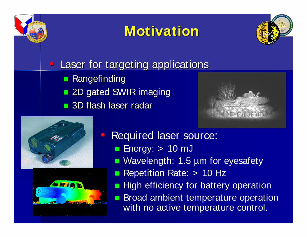
MotivationMotivation
•• Laser for targeting applicationsLaser for targeting applicationsRangefindingRangefinding2D gated SWIR imaging 2D gated SWIR imaging 3D flash laser radar3D flash laser radar
• Required laser source:Energy: > 10 mJWavelength: 1.5 µm for eyesafetyRepetition Rate: > 10 Hz High efficiency for battery operationBroad ambient temperature operation with no active temperature control.

MonoblockMonoblock LaserLaser
Cr:YAGOD=0.29
Nd:YAG Nd:YAG KTP OPO
HR 1.06 mAR 808 nm
μ
HR 1.54 mAR 1.06 m
μμ
HR 1.06 mOC 1.54 m
μμ
Brewster's angle
30 mm
Undoped YAG
The transmitter design is based on a Nd:YAG laser with a Cr4+ passive Q-switch and an intracavity KTP OPO.
The transmitter design is based on a Nd:YAG laser with a Cr4+ passive Q-switch and an intracavity KTP OPO.
Flashlamp-pumped version in limited production in STORM MFL and in experimental imaging systems (gated SWIR, 3D Ladar)
Flashlamp-pumped version in limited production in STORM MFL and in experimental imaging systems (gated SWIR, 3D Ladar)
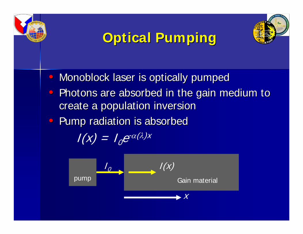
Optical PumpingOptical Pumping
•• MonoblockMonoblock laser is optically pumpedlaser is optically pumped•• Photons are absorbed in the gain medium to Photons are absorbed in the gain medium to
create a population inversioncreate a population inversion•• Pump radiation is absorbed Pump radiation is absorbed
I(x) = I0e-α(λ)x
pump Gain material
I0 I(x)
x

Optical Pumping and Optical Pumping and Nd:YAGNd:YAG AbsorptionAbsorption
6
5
4
3
2
1
0
abs
orpt
ion
coef
ficie
nt (
cm-1 )
830820810800790780
wavelength (nm)
30
25
20
15
10
5
0
Pu
mp inte
nsity
alpha
YAG
•• Pump radiation is absorbed Pump radiation is absorbed I(x) = I0e-α(λ)x
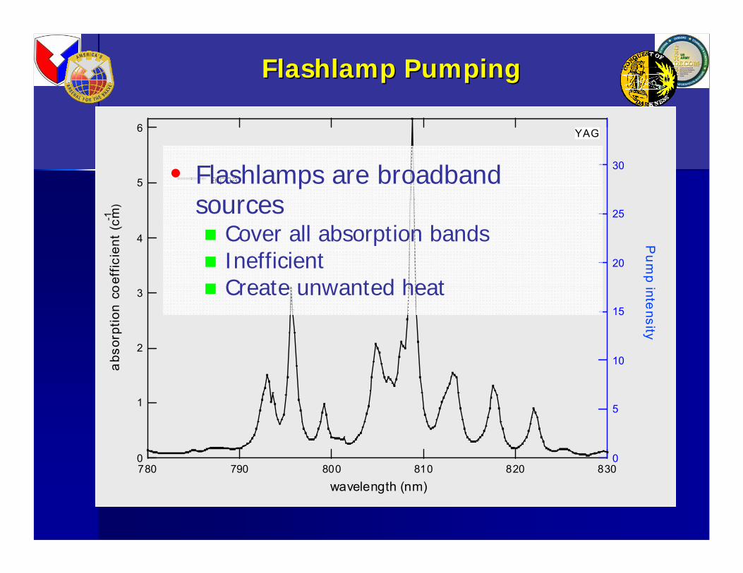
FlashlampFlashlamp PumpingPumping
6
5
4
3
2
1
0
abs
orpt
ion
coef
ficie
nt (
cm-1 )
830820810800790780
wavelength (nm)
30
25
20
15
10
5
0
Pu
mp inte
nsity
alpha
YAG
• Flashlamps are broadband sources
Cover all absorption bandsInefficientCreate unwanted heat
Diode Pumping Diode Pumping Nd:YAGNd:YAG
6
5
4
3
2
1
0
abs
orpt
ion
coef
ficie
nt (
cm-1 )
830820810800790780
wavelength (nm)
30
25
20
15
10
5
0
Pu
mp inte
nsity
a lpha pump
YAG
Diode center wavelength 808 nm, 4 nm FWHM

Diode Pumping Diode Pumping Nd:YAGNd:YAG
6
5
4
3
2
1
0
abs
orpt
ion
coef
ficie
nt (
cm-1 )
830820810800790780
wavelength (nm)
30
25
20
15
10
5
0
Pu
mp inte
nsity
a lpha pump
YAG
Diode center wavelength 801 nm, 4 nm FWHM

Diode Pumping Diode Pumping Nd:YAGNd:YAG
6
5
4
3
2
1
0
abs
orpt
ion
coef
ficie
nt (
cm-1 )
830820810800790780
wavelength (nm)
30
25
20
15
10
5
0
Pu
mp inte
nsity
a lpha pump
YAG
Diode center wavelength 801 nm, 4 nm FWHM
•• Pump radiation is absorbed Pump radiation is absorbed I(x) = I0e-α(λ)x
•• Absorption length Absorption length

Absorption length vs. Wavelength Absorption length vs. Wavelength
Beer’s Law for Nd:YAGshows absorption length required to absorb N% of pump radiation for N = 60, 70, 80, 90
6
5
4
3
2
1
0
abso
rptio
n le
ngth
[cm
]
815810805800795790wavelength [nm]
% Absorption 90% 80% 70% 60%

SideSide--pumped pumped MonoblockMonoblock
pump wavelength [nm]
794 796 798 800 802 804 806 808 810
perc
ent o
f ene
rgy
abso
rbed
0
20
40
60
80
100
Diode Temperature [degrees C]
-20 -10 0 10 20 30 40 50
Sid
e-pu
mpe
d ou
tput
ene
rgy
[mJ]
1
2
3
4
5
6
7
percent absorption for 8.5 mmoutput energy
1.5 μm output only at temperatures corresponding to favorable absorption

Diode ArrayDiode Array
These arrays consist of 12 bar stacks of nominally 100 W/bar diode bars, for a total of 1200 W, in Coherent’s standard G-stack package.
12-bar pump-diode mounted on aluminum heat sink shows thermocouple location
Drawing of the alignment fixture, lens being aligned and
partially lensed laser-diode array

EndEnd--Pumping TechniquesPumping Techniques
Non-imaging techniques for light concentration
4 mm
4 mm
11 mm
5 mm
Lens duct
Reflective concentrator

Diode CharacterizationDiode Characterization
Pump diode wavelength vs. temperature for two diode arrays. Data taken under constant current (100A) constant pulsewidth (200 µs) condition.
Pump diode pulse energy vs. temperature for two diode arrays. Data taken under constant current (100A) constant pulsewidth (200 µs) condition.
Temperature (degr C)
-20 -10 0 10 20 30 40 50
Ener
gy [m
J] (@
100
A, 2
00 μ
s)
0
50
100
150
200
250
300
lensed diode array bare diode array
Temperature (degrees C)
-20 -10 0 10 20 30 40 50
Wav
elen
gth
(nm
)
790
795
800
805
810
815
lensed diode arraybare diode array
Temperature Testing Temperature Testing BuildBuild--up Timeup Time
Temperature [degrees C]
-20 -10 0 10 20 30 40 50
build
-up
time
[mic
rose
cond
s]
0
50
100
150
200
250
bare diode array with concentratorlensed diode array with cylindrical lensbare diode array with lens duct

Temperature Testing Temperature Testing 1.5 um Energy1.5 um Energy
Temperature [degrees C]
-20 -10 0 10 20 30 40 50
outp
ut e
nerg
y [m
J]
0
2
4
6
8
10
12
14
bare diode array with concentratorlensed diode array with cylindrical lensbare diode array with lens duct

1.06 1.06 μμm m FluorescenceFluorescenceLensedLensed CaseCase
1.06 μm fluorescence due to end-pumping
with lensed diode array at 30°C
1.06 μm fluorescence due to end-pumping
with lensed diode array at 12°C

1.06 1.06 μμm m FluorescenceFluorescenceConcentrator CaseConcentrator Case
1.06 μm fluorescence due to end-pumping with bare diode array coupled into Nd:YAG rod by reflective concentrator
14°C
30°C
Temperature TestingTemperature TestingOptical to optical efficiencyOptical to optical efficiency
Temperature [degrees C]
-20 -10 0 10 20 30 40 50
optic
al-to
-opt
ical
effi
cien
cy
0.00
0.01
0.02
0.03
0.04
0.05
0.06
0.07
bare diode array with concentratorlensed diode array with cylindrical lensbare diode array with lens duct
ConclusionsConclusions
• The next generation monoblock laser, a low-cost, compact, and rugged transmitter with application to eyesafe rangefinding and other targeting scenarios.
• Investigated several end-pumping schemes with application to the monoblock laser
• Experimantally compared the configurations over a 70°C temperature span from -20°C to 50°C
• Each of the tested end-pump configurations gave complete operation over the full temperature range.
• We have addressed the need for an eyesafe laser transmitter operating in the millijoule regime at tens of Hz repetition rate with optical to optical efficiency of 1-5%.