emo ml c192c 14-channel power supply system employing ... · 1 1962 emo ml c192c description...
TRANSCRIPT
1dc1962cf
DEMO MANUAL DC1962C
Description
14-Channel Power Supply System Employing LTC3880/LTC2974/LTC2977
Power System Managers with EEPROM
The DC1962C is a demonstration system that showcases three different Linear Technology devices—the LTC®3880, LTC2974, and LTC2977. The LTC2974 and LTC2977 devices are I2C/SMBus/PMBus power system managers with EEPROM. The LTC3880 is a dual output PolyPhase® step-down DC/DC control-ler with digital power system management. The LTC3880 moni-tors and controls 2 power supply rails, the LTC2974 monitors and controls 4 power supply rails, and the LTC2977 monitors and controls 8 power supply rails. The DC1962C demonstrates the ability of these devices to sequence, trim, margin, supervise, monitor, and log faults for fourteen power supplies. Each power supply channel’s output voltage is monitored and each device monitors its own internal die temperature. Six channels have current and external temperature sensing.
The DC1962C is a single circuit board that contains fourteen independent power supply rails. The board employs twelve LTC3405A 300mA switch-mode regulators, which are config-ured to be controlled by the LTC2974 (4) and LTC2977 (8). The LTC3880’s two channels have much of the switching regulator integrated, only requiring the external power stage (power MOSFETs), inductor, and other passives. This board provides a sophisticated fourteen channel digitally programmable power supply system. The rail voltages are programmable within the trim range shown in Table 1.
This demonstration system is supported by the LTpowerPlay™ graphical user interface (GUI) enabling complete control of the features on all three devices. Together, the LTpowerPlay software and DC1962C hardware system create a powerful development environment for designing and testing configuration settings of the LTC3880, LTC2974, and LTC2977. These settings can be stored in each of the devices’ internal EEPROM or in a file. This file can later be used to order pre-programmed devices or to program devices in a production environment. The software displays all of the configuration settings and real time measure-ments from the three digital power ICs. Telemetry allows easy access and decoding of the fault log created by each device. The board comes pre-programmed with the EEPROM values appropriate for the fourteen power supply rails on the DC1962C. Just plug and play!
Multiple DC1962C boards can be cascaded together to form a high channel count power supply (see the Multi-Board Arrays section). This allows for the formation of a single, coherent
L, LT, LTC, LTM, Linear Technology, the Linear logo and PolyPhase are registered trademarks and LTpowerPlay is a trademark of Linear Technology Corporation. All other trademarks are the property of their respective owners.
power supply system. The user configures up to eight DC1962C boards, thereby controlling up to 112 separate power supply rails. This cascaded configuration demonstrates features of the LT power system management ICs which enable timing and fault information to be shared across multiple ICs.
The DC1962C demo board can be powered by an external power supply, such as a +12VDC supply. Communication with the software is provided through the DC1613 USB-to-I2C/SMBus/PMBus Controller. The following is a checklist of items which can be obtained from the LTC website or LTC Field Sales.
• USB-to-I2C/SMBus/PMBus Controller (DC1613)• LTpowerPlay Software
DC1962C Features• I2C/SMBus Serial Interface• PMBus Compliant Command Set• Configuration EEPROM with CRC• Black Box Fault Logging to Internal EEPROM• Differential Input, 16-Bit Δ∑ ADC with less than ±0.25% of
Total Unadjusted Error (±0.5% for LTC3880)• Voltage Servos Precisely Adjust Supply Voltages • LTC2974 and LTC2977 Utilize 10-Bit trim DACs with
Soft-Connect• Telemetry Reads Back VIN, IIN, VOUT, IOUT, Temperature (Int.
and Ext.)• Output Sequencer - Time Based or Tracking (Tracking support
on LTC2974 Only)• Supports Multichannel Fault Management• Operates Autonomously without Additional SW• Powered from 6V to 14V• Packaging: – LTC2974/LTC2977 in 64-lead QFN – LTC3880 in 40-lead QFN
Design files for this circuit board are available at http://www.linear.com/demo

2dc1962cf
DEMO MANUAL DC1962C
performance summary Specifications are at TA = 25°C
POWER SUPPLY CHANNEL CH(0:1) CH(2:5) CH(6:13)
Manager/Controller LTC3880 LTC2974 LTC2977
Nominal Untrimmed Output Voltages 0.85V, 1.1V (Defined by Config)
1.5V, 1.8V, 2.0V, 2.2V 0.9V, 1.0V, 1.1V, 1.2V, 2.5V, 2.7V, 3.0V, 3.3V
Rated Output Current 0.3A
Default Margin Range ± 5%
Output Trim Range (VFS_VDAC = 1.38V) Each Channel Is Adjustable from 0.5V to 4.5V (Note 1)
15%/–11% 15%/–11%
Temperature 1 Internal, 2 Ext. 1 Internal, 4 Ext. 1 Internal
Common Characteristics. Specifications Valid Over Full Operating Temperature Range
PARAMETER CONDITIONS
VALUE
MIN TYP MAX UNITS
VPWR Supply Input Voltage Range 6 14 V
ADC Total Unadjusted Error VIN_ADC ≥ 1V, Applies to LTC2974/LTC2977 ±0.25 %
VIN_ADC ≥ 1V, Applies to LTC3880 ±0.5 %
ADC Voltage Sensing Input Range Differential Voltage: VIN_ADC = (VSENSEPn – VSENSEMn) 0 6 V
Note 1: Note that VOUT_MAX limit is set to 2.5V by default. VOUT_MAX clamps the voltage setpoint to 2.5V. It is recommended that you change the VOUT_MAX register and associated VOUT FAULT limit registers when changing VOUT to prevent the channel from faulting off.
The following list contain terms used throughout the document.
Channel – The collection of functions that monitor, supervise, and trim a given power supply rail.
EEPROM – Non-volatile memory (NVM) storage used to retain data after power is removed.
Margin – Term used typically in board level testing that increases/decreases the output voltage to look for sensitivity/marginality problems
NVM – Non-volatile memory, see EEPROM.
Monitor – The act of measuring voltage, current, and temperature readings.
PMBus – An industry standard power-management protocol with a fully defined command language that facilitates communication with power converters and other devices in a power system.
Rail – The final output voltage that the power supply controller manages.
Supervise – The act of quickly responding (warning or faulting) to a voltage, current, temperature condition that is compared to pre-programmed values.
Trim – The act of adjusting the final output voltage. A servo loop is typically used to trim the voltage.
Glossary of terms

3dc1962cf
DEMO MANUAL DC1962C
ltpowerplay Gui softwareLTpowerPlay is a powerful Windows-based development environment that supports Linear Technology power system management ICs with EEPROM, including the LTC2974 and LTC2977 4-channel and 8-channel PMBus power system managers, and the LTC3880 dual output PolyPhase step-down DC/DC controller with digital power system manage-ment. The software supports a variety of different tasks. You can use LTpowerPlay to evaluate Linear Technology ICs by connecting to a demo board system. LTpowerPlay can also be used in an offline mode (with no hardware present) in order to build a multi-chip configuration file that can be saved and re-loaded at a later time. LTpowerPlay provides unprecedented system level diagnostic and debug features. It becomes a valuable diagnostic tool during board bring-up to program or tweak the power management scheme in a system or to diagnose power issues when bringing up rails. LTpowerPlay utilizes the DC1613 I2C/SMBus/PMBus Controller to communicate with one of many potential targets, including the DC1962C demo system or a customer board. The software also provides an automatic update feature to keep the software current with the latest set of device drivers and documentation. The LTpowerPlay software can be downloaded from:
http://www.linear.com/ltpowerplay
Figure 1. Screenshot of the LTpowerPlay GUI
4dc1962cf
DEMO MANUAL DC1962C
Quick start proceDureTo access technical support documents for LTC Digital Power Products visit “Help, View Online help” on the LTpow-erPlay menu.
The following are examples of content available in the online help:
1. Demonstration and Tutorial Videos
• An updated Quick Start Demonstration video of LTpowerPlay and this demo board
• Product/Feature-specific demonstration and tutorial videos
2. Detailed Technical Documentation
• Schematic Checklists
• Device Programming Options
• Firmware ‘Getting Started’ guides with sample code (margining, reading telemetry, etc.)
The following procedure describes how to set up a DC1962C demo system.
1. Download and install the LTpowerPlay GUI: www.linear.com/ltpowerplay
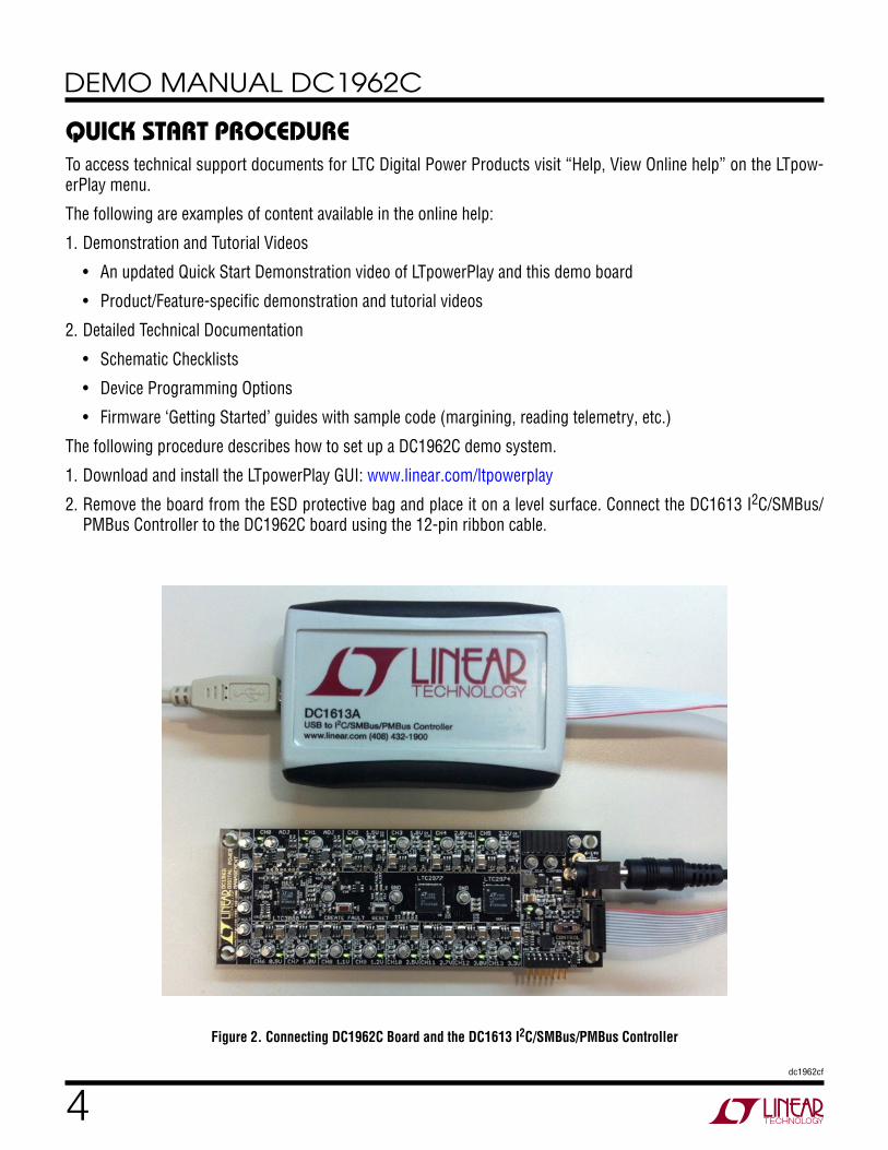
2. Remove the board from the ESD protective bag and place it on a level surface. Connect the DC1613 I2C/SMBus/PMBus Controller to the DC1962C board using the 12-pin ribbon cable.
Figure 2. Connecting DC1962C Board and the DC1613 I2C/SMBus/PMBus Controller
5dc1962cf
DEMO MANUAL DC1962C
3. Confirm that the CONTROL switch is set to the RUN position.
4. Plug the USB-to-I2C/SMBus/PMBus Controller into a USB port on your PC. The board should power up with all power good LEDs and 5V LED illuminated green. The USB-to-I2C/SMBus/PMBus Controller supplies ~100mA of current which should be sufficient for a single demo board.
5. Connect a 12VDC power supply with > 0.5A capacity to the VIN input jack of any DC1962C, if multiple boards are being powered.
6. Launch the LTpowerPlay GUI.
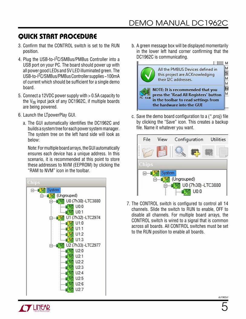
a. The GUI automatically identifies the DC1962C and builds a system tree for each power system manager. The system tree on the left hand side will look as below:
Note: For multiple board arrays, the GUI automatically ensures each device has a unique address. In this scenario, it is recommended at this point to store these addresses to NVM (EEPROM) by clicking the “RAM to NVM” icon in the toolbar.
b. A green message box will be displayed momentarily in the lower left hand corner confirming that the DC1962C is communicating.
Quick start proceDure
c. Save the demo board configuration to a (*.proj) file by clicking the “Save” icon. This creates a backup file. Name it whatever you want.
7. The CONTROL switch is configured to control all 14 channels. Slide the switch to RUN to enable, OFF to disable all channels. For multiple board arrays, the CONTROL switch is wired to a signal that is common across all boards. All CONTROL switches must be set to the RUN position to enable all boards.
6dc1962cf
DEMO MANUAL DC1962C
Quick start proceDureLoading a DC1962C Configuration (*.proj) File with the GUI
1. In the upper left hand corner of the GUI, File > Open > browse to your *.proj file. This will load the file into the GUI.
2. Click on the “Go Online” icon, then click on the “PC → RAM” icon. This loads the configuration into the working RAM of the devices.
3. To store the configuration to NVM (EEPROM), click on the “RAM → NVM” icon as shown below.
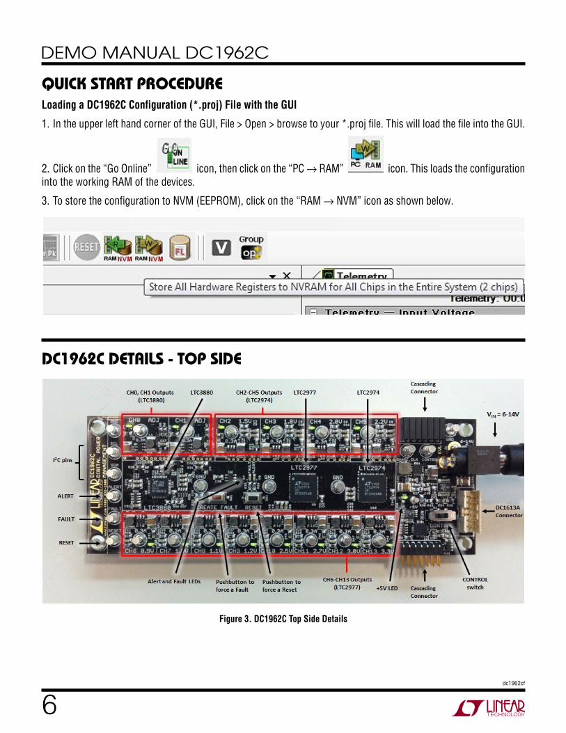
Dc1962c Details - top siDe
Figure 3. DC1962C Top Side Details

7dc1962cf
DEMO MANUAL DC1962C
common Demo BoarD operationsMargin All Rails
The digital power products on the DC1962C not only monitor each of their respective outputs but can margin the outputs either high or low. Margining is the operation that moves a rail either up or down for testing purposes. It allows a system to be fully characterized over supply limits without the use of external hardware or resources. The GUI provides an easy way to margin all rails high or all low by clicking one of four buttons. To invoke the margining dialog, click the GroupOp icon in the toolbar.
The buttons labeled “ignore faults” will margin without creating a fault even if the fault limits are exceeded (LTC2974 and LTC2977 only).
A look at the telemetry window shows the effect of the margin high or margin low operation. The following screen shot shows all rails going from nominal set points to margin high, margin low, and back to nominal voltages.
Each of the power management ICs has a multiplexed ADC that is used to provide voltage, current, and temperature readback values. The telemetry plot in the GUI is similar to a multichannel oscilloscope which is capable of displaying any parameter that is displayed in the telemetry window. Due to the nature of a multiplexed ADC converter, it has an associated ADC loop time. The total ADC loop time (~100ms to 160ms) for a given channel is dependent on the device’s configuration. See corresponding data sheet.

8dc1962cf
DEMO MANUAL DC1962C
Creating a Fault
There is a pushbutton on the DC1962C board that is used to force a fault and demonstrate the demo board’s ability to detect it and respond according to the configuration. When depressed, the pushbutton creates a fault on channel 2, the 1.5V output (GUI channel U1:0). The user should see all outputs power off, the fault LED momentarily il-luminate, the alert LED illuminate continuously, and all rails sequence back on after a retry period. The user may also short any power supply output indefinitely. This is a good way to induce UV faults and shows that a shorted channel will not be damaged. Use a jumper wire or a coin to short any output.
common Demo BoarD operationsClearing a Fault
To clear a fault, the user may click the CF icon in the GUI or simply push the RESET pushbutton on the demo board. In both cases, the red (+) on the CF icon and alert LED on the board will be cleared. You will notice that all rails are automatically re-enabled after a programmable retry period. The alert LED may be cleared by clicking the Clear Faults (CF) icon in the GUI. After clearing faults, the system tree may remain “yellow” if any non-volatile fault logs are present. For further information, see the Working with the Fault Log section.
Reset the DC1962C
A reset pushbutton is provided on the board. To reset all devices on the DC1962C board and reload the EEPROM contents into operating memory (RAM), press RESET (SW2) on the DC1962C. Note that the “RESET” icon in the GUI tool bar issues a software reset for any LTC3880 device in the system. It is recommended that you use the reset pushbutton on the board to provide a reset condition to the entire system.
DC1962C LEDs
Each individual channel on DC1962C also has its own green power good LED (RUN_CH0 through RUN_CH13). When USB power (DC1613 Controller) or external power (6V to 14V jack) is applied, the +5V green LED will illu-minate, indicating that the power system managers are powered. The red LEDs will illuminate when an alert or a fault has occurred.

9dc1962cf
DEMO MANUAL DC1962C
Figure 4. Sequencing Output Channels with DC1962C Using TON_DELAY
common Demo BoarD operations
Figure 5. TON_DELAY Configuration Figure 6. TOFF_DELAY Configuration
Sequencing Output Channels
The LTC3880, LTC2974, and LTC2977 have been pre-configured with different TON_DELAY values for each channel. The TON_DELAY parameter is applied to each device relative to the respective CONTROL pin (RUN on the LTC3880). On this demo board, all CONTROL/RUN pins are wire OR’d. Therefore the TON and TOFF delays are enforced relative to one edge. Figure 4 shows an oscil-loscope screen capture of four output rails sequencing up.
The same applies to TOFF_DELAY values. When the CONTROL switch is set to the OFF position, all rails will
power down sequentially based on each of the device’s TOFF_DELAY values. Each channel has an LED which visually indicates if the channel has power. When the CONTROL pin is switched on and off, you will observe the relative on/off timing of the 14 channels. Figures 5 and 6 show TON and TOFF delays for all channels at once. You will notice in Figure 1 that the GUI shows idealized on/off waveforms. This graphical view shows the relative TON and TOFF delays in response to an on/off command, whether it comes from the CONTROL switch or PMBus command. Once a new timing value is entered, the timing change will be reflected in the idealized waveforms.

10dc1962cf
DEMO MANUAL DC1962C
"Why Am I Off?” Tool
Use the “Why am I Off?” tool in the LTpowerPlay GUI to diagnose the reason a power supply channel is turned off. The tool can be located in the top right corner of the GUI, above the Register Information tab. Hover your cursor over this tab to show the tool.
common Demo BoarD operations
Figure 7. "Why Am I Off” Tool in the LTpowerPlay GUI
What Is a Fault Log?
A fault log is a non-volatile record of the power system leading up to the time of fault. It holds the most recent monitored values (uptime, voltage, current, temperature) that can be analyzed to help determine the cause of the fault. It is a powerful diagnostic feature of each of the digital power managers on the DC1962C demo board.
Create a Fault and Fault Log
To create a fault log, you must create a fault, as described in the Creating a Fault on page 8. Select the appropriate device in the system tree by clicking on the U1 LTC2974 chip. We will proceed to work with the LTC2974 fault log.
aDvanceD Demo BoarD operations

11dc1962cf
DEMO MANUAL DC1962C
aDvanceD Demo BoarD operationsWorking with the Fault Log
Once a fault has occurred, the Fault Log (FL) icon will show a red (+) sign on it, indicating that the GUI has detected a fault log in one of the devices. Clicking the icon will bring up a dialog box. Note that it is context sensitive. Be sure that the desired device is selected in the system tree.
Notice that the checkbox “Log to EEPROM on Fault” is checked. Once a fault occurs, the device will automatically write the fault log data to EEPROM (NVM). At this point, the log is locked and will not change until it is cleared by the user. To read the EEPROM log data, first click the
“EEPROM to RAM” button. At this point the RAM Log is locked and not updated even though the telemetry read-ings continue. Click the “Read NVM Log” button. The log data will appear in the text box below.
The log contains timestamp, up-time, channel voltage readings, an input voltage reading, an on-chip temperature reading, etc. There will be a number of loops; each loop contains data obtained in one ADC loop time with the most recent ADC loop data on top and the oldest data at the bottom of the log. The up-time indicates, at the time of fault, the amount of time the device has been powered up or time since the previous reset.
In this case, the fault log will show that channel U1:0 faulted due to a VOUT_UV_FAULT condition. On the pre-vious telemetry loop, the channel voltage reading was a nominal value (1.5V).
To clear the fault log, click the “Clear/Rearm EEPROM Log” button. This allows the selected device to be ready for a new fault event.

12dc1962cf
DEMO MANUAL DC1962C
aDvanceD Demo BoarD operationsFault Sharing Setup in the GUI
Fault sharing provides a means of propagating a fault detected by a power manager to other power managers via FAULT pins. Use the Fault Sharing Setup Tool to configure the fault sharing in the GUI. Select the LTC2974 in the system tree. Go to Utilities > Fault Sharing Diagram. For more details on this topic, please refer to the MFR_FAULTB propagate and response sections in the data sheet.
channels on the DC1962C demo board since the fault pins are tied together.
NOTE: All FAULT pins on all power managers are tied to-gether on the DC1962C demo board. These pins are open drain and have a common pull-up resistor to provide a logic high level (inactive). All FAULT pins are active low.
There are two types of actions to fault conditions: How a channel responds to another channel’s fault and whether a particular channel propagates its fault to other channels. FAULT pins are bi-directional, meaning the device may drive its fault pin low (output) or may respond to the fault pin when another device drives it low (input). Because all fault pins are wire OR’d on the DC1962C, this hardware configuration allows one to program each device’s fault settings on a channel-by-channel basis. By default, the LTC2974 is configured to shut down its channels if other devices fault and to propagate its own fault via the FAULT pins. The LTC2977 is configured the same as the LTC2974, however zone 1 (U2:4-U2:7) is configured to not propagate a fault. A fault on these channels will cause only that channel to fault off. You can think of the “Response” switches as “shut this channel down when another channel faults”, and the “Propagate” switches as “drive a fault pin to broadcast to other channels that this channel faulted.”
Figure 8. Fault Sharing Utility in LTpowerPlay GUI
The LTC2974 fault sharing dialog will appear as shown in Figure 8. All Response and all Propagate switches are closed by default. In this configuration, a fault on an LTC3880 or LTC2977 channel will shut down all LTC2974 channels, and a fault on any LTC2974 channel will propagate to all
13dc1962cf
DEMO MANUAL DC1962C
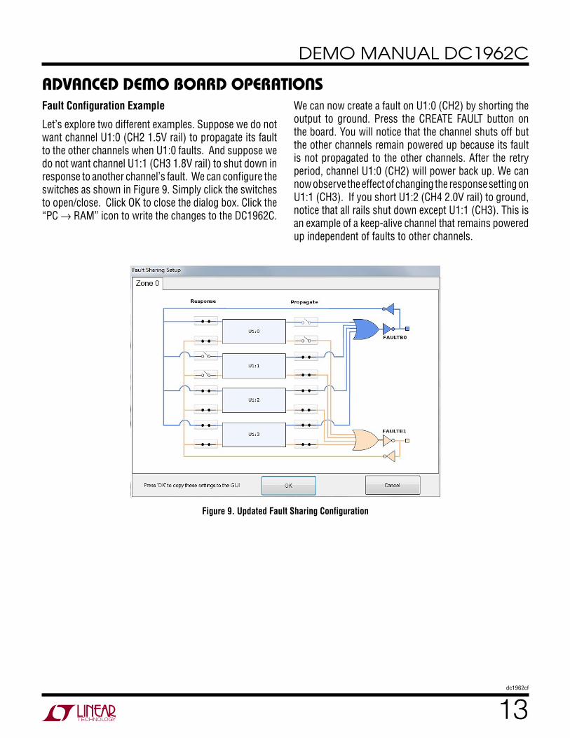
Figure 9. Updated Fault Sharing Configuration
Fault Configuration Example
Let’s explore two different examples. Suppose we do not want channel U1:0 (CH2 1.5V rail) to propagate its fault to the other channels when U1:0 faults. And suppose we do not want channel U1:1 (CH3 1.8V rail) to shut down in response to another channel’s fault. We can configure the switches as shown in Figure 9. Simply click the switches to open/close. Click OK to close the dialog box. Click the “PC → RAM” icon to write the changes to the DC1962C.
We can now create a fault on U1:0 (CH2) by shorting the output to ground. Press the CREATE FAULT button on the board. You will notice that the channel shuts off but the other channels remain powered up because its fault is not propagated to the other channels. After the retry period, channel U1:0 (CH2) will power back up. We can now observe the effect of changing the response setting on U1:1 (CH3). If you short U1:2 (CH4 2.0V rail) to ground, notice that all rails shut down except U1:1 (CH3). This is an example of a keep-alive channel that remains powered up independent of faults to other channels.
aDvanceD Demo BoarD operations

14dc1962cf
DEMO MANUAL DC1962C
aDvanceD Demo BoarD operations
Up to eight DC1962C boards can be cascaded to control up to 112 independent power supplies. The number of boards is limited by an I/O expander chip that has three address pins, allowing 8 different combinations. This setup demonstrates the coordinated fault responses and accurate time base shared across multiple power system managers.
Procedure:
1. Stack the boards side-by-side by plugging JP1 of one board into JP2 of another DC1962C board.
2. Ensure different slave address settings for each of the boards. The address of each DC1962C board is deter-mined by pins A2, A1 and A0 of the DIP switch JP1 on the backside of the board. The setting must be unique for each board in the array.
3. Plug in the +12V VIN power into one of the boards as shown in Figure 10. Only one +12V power source is allowed.
setup proceDure for multiBoarD arrays
The two LTC3880 channels can be uniquely configured and any fault can be propagated or not. Since the LTC3880 GPIO pins are tied together, a fault on CH0 may be used to
turn off CH1. This is achieved by setting the appropriate MFR_GPIO_PROPAGATE command code and the MFR_GPIO_RESPONSE command to “inhibit.”

15dc1962cf
DEMO MANUAL DC1962C
setup proceDure for multiBoarD arrays
Figure 10. Array of Multiple DC1962C Demo Boards
4. The USB-to-I2C/SMBus/PMBus Controller may be plugged into any board. If no DC1962C boards show up in the GUI, click the magnifying glass icon to enumer-ate the I2C bus and find the addresses of the parts. Go to step #2 to ensure that each board has a unique DIP switch setting.
5. Since the individual CONTROL lines are connected across the boards (CTRL is a common signal across all boards in the array), make sure that all CONTROL switches are set to the RUN position.
6. Re-launch LTpowerPlay. After launching, LTpowerPlay will enumerate the entire board array and build a rep-resentative system tree and read all hardware settings into the GUI.
ATTENTION: Once the GUI has launched, click the “RAM → NVM” button in the tool bar to ensure that the slave addresses are retained after a power off or reset. Other-wise you may lose communication with the slaves after a power cycle or reset event.

16dc1962cf
DEMO MANUAL DC1962C
Ensuring Slave Addresses Do Not Conflict
There is a small DIP switch on the backside of the DC1962C. It is used to set the slave address of an I/O expander which allows the addition of multiple boards to a setup. The I/O
setup proceDure for multiBoarD arraysexpander has a base address of 0x20. The DIP switch settings set the offset. The three switches that may be changed are labeled A0, A1, A2. Examples below set the boards to address 0x20 and 0x27.
Figure 11. DIP Switch Set to All 0's
Figure 12. DIP Switch Set to All 1's

17dc1962cf
DEMO MANUAL DC1962C
Dc1962c Details - top
Table 3. DC1962C - Default Switch Configuration (Default Position Shown in Grey in the Figure Above)REFERENCE DESIGNATOR SIGNAL NAME USAGE DEFAULT
JP3 A0, A1, A2 DIP switch used to set the address offset OPEN
S1 CONTROL0 Switch used to enable/disable the CONTROL0 input pin of LTC3880, LTC2974, and LTC2977
RUN
18dc1962cf
DEMO MANUAL DC1962C
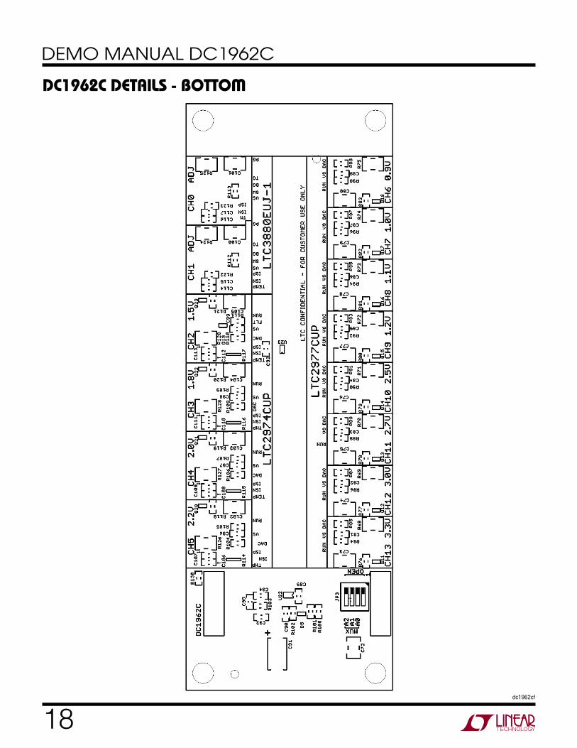
Dc1962c Details - Bottom

19dc1962cf
DEMO MANUAL DC1962C
parts listITEM QTY REFERENCE PART DESCRIPTION MANUFACTURER/PART NUMBER
Required Circuit Components
1 1 U8 IC DUAL PolyPhase CONTROLLER 40-QFN Linear Technology: LTC3880EUJ-1
2 1 U9 IC 8-CH PWR SYSTEM MANAGER 64-QFN Linear Technology: LTC2977CUP
3 1 U10 IC 4-CH PWR SYSTEM MANAGER 64-QFN Linear Technology: LTC2974CUP
Additional Demo Board Circuit Components
4 12 C1, C3, C5, C7, C64, C65, C66, C67, C68, C69, C70, C71
CAP CER 220pF 50V 10% NPO 0603 NIC: NMC0603NPO221J50TRPF
5 8 C2, C4, C6, C8, C9, C10, C11, C12 CAP CER 2200pF 50V 20% X7R 0603 Murata: GRM188R71H222MA01D
6 30 C13, C14, C15, C16, C25, C26, C31, C43, C44, C46, C47, C49, C50, C51, C52, C81, C82, C83, C84, C85, C86, C87, C88, C92, C96, C97, C98, C99, C115, C117
CAP CER 0.1µF 16V 10% X7R 0603 NIC: NMC0603X7R104K16TRPF
7 11 C17, C18, C106, C107, C108, C109, C110, C111, C112, C113, C118
CAP CER 10000pF 50V 10% X7R 0603 TDK: C1608X7R1H103K
8 16 C19, C20, C21, C22, C23, C24, C32, C53, C54, C55, C56, C57, C58, C59, C60, C72
CAP CER 10µF 10V 10% X5R 1210 Kemet: C1210C106K8PACTU
9 3 C27, C90, C93 CAP CER 4.7µF 16V 10% X5R 0603 TDK: C1608X5R1C475K
10 1 C28 CAP CER 10µF 25V 20% X5R 1210 Taiyo Yuden: TMK325BJ106MM-T
11 2 C29, C34 CAP CER 3300pF 50V 10% X7R 0603 Murata: GRM188R71H332KA01D
12 13 C30, C36, C39, C41, C42, C45, C48, C61, C62, C63, C89, C114, C116
CAP CER 1µF 16V 10% X7R 0603 Taiyo Yuden: EMK107B7105KA-T
13 2 C33, C37 CAP CER 100pF 50V 10% X7R 0603 AVX: 06035C101KAT2A
14 2 C35, C95 CAP CER 68pF 50V 5% NPO 0603 AVX: 06035A680JAT2A
15 13 C38, C73, C74, C75, C76, C77, C78, C79, C80, C102, C103, C104, C105
CAP CER 22µF 10V 10% X5R 1210 Kemet: C1210C226K8PACTU
16 1 C40 CAP CER 47pF 50V 5% NPO 0603 AVX: 06035A470JAT2A
17 1 C91 CAP TANT 47µF 16V 20% 7343 Kemet: T520D476M016ATE035
18 1 C94 CAP CER 4.7pF 50V NPO 0603 Murata: GRM1885C1H4R7CZ01D
19 2 C100, C101 CAP CER 47µF 10V 20% X7R 1210 Murata: GRM32ER71A476ME15L
20 4 D1, D2, D3, D4 DIODE SCHOTTKY 20V 1A SOD323 NXP Semiconductors: PMEG2010EA,115
21 1 D5 DUAL SCHOTTKY DIODE 30V CC SOT-323-3 STMicroelectronics: BAT30CWFILM
22 2 L1, L2 INDUCTOR SHLD POWER 10.0µH SMD Abracon Corporation: ASPI-0315FS-100M-T2
23 12 L3, L4, L5, L6, L8, L9, L10, L11, L12, L13, L14, L15
INDUCTOR SHLD POWER 4.7µH SMD Abracon Corporation: ASPI-0315FS-4R7M-T2
24 1 L7 INDUCTOR POWER 2.2µH 2.85A SMD Vishay: IHLP1616BZER2R2M01
25 15 P1, P2, P3, P4, P5, P6, P9, P10, P11, P12, P13, P14, P15, P16, P17
LED GREEN HIGH BRIGHT ESS SMD Panasonic: LNJ337W83RA
26 2 P7, P8 LED RED HI BRT SS TYPE LO CUR SM Panasonic: LNJ208R8ARA
27 2 Q1, Q2 MOSFET N-CH DUAL 20V SSOT-6 Fairchild Semiconductor: FDC6401N
28 1 Q10 MOSFET P-CH 8V 860MA SOT323-3 Vishay/Siliconix: SI1305DL-T1-E3
29 6 Q3, Q4, Q5, Q6, Q7, Q8 TRANS GP SS PNP 40V SOT323 ON Semiconductor: MMBT3906WT1G
30 14 Q9, Q11, Q12, Q13, Q14, Q15, Q16, Q17, Q18, Q19, Q20, Q21, Q22, Q23
MOSFET N-CH 30V 900MA SOT323-3 Vishay/Siliconix: SI1308EDL-T1-GE3

20dc1962cf
DEMO MANUAL DC1962C
parts listITEM QTY REFERENCE PART DESCRIPTION MANUFACTURER/PART NUMBER
31 21 R1, R2, R3, R4, R29, R60, R61, R62, R63, R76, R77, R78, R79, R80, R81, R82, R83, R118, R119, R120, R121
RES 100k 1/10W 1% 0603 SMD Vishay: CRCW0603100KFKEA
32 4 R5, R6, R7, R8 RES 1.50k 1/10W 1% 0603 SMD Yageo: RC0603FR-071K5L
33 15 R9, R10, R15, R16, R17, R18, R38, R41, R42, R43, R44, R45, R46, R47, R48
RES 3.01k 1/10W 1% 0603 SMD Yageo: RC0603FR-073K01L
34 1 R11 RES 115k 1/10W 1% 0603 SMD Vishay: CRCW0603115KFKEA
35 1 R12 RES 80.6k 1/10W 1% 0603 SMD Vishay: CRCW060380K6FKEA
36 1 R13 RES 66.5k 1/10W 1% 0603 SMD Vishay: CRCW060366K5FKEA
37 1 R14 RES 57.6k 1/10W 1% 0603 SMD Vishay: CRCW060357K6FKEA
38 9 R19, R24, R33, R49, R58, R59, R100, R101, R130
RES 10.0k 1/10W 1% 0603 SMD Vishay: CRCW060310K0FKEA
39 4 R20, R21, R112, R113 RES 4.7Ω 1% 0603 SMD Vishay: CRCW06034R70FKEA
40 2 R22, R23 RES 13.3k 1/10W 1% 0603 SMD NIC: NRC06F1332TRF
41 4 R25, R26, R122, R123 RES 698Ω 1/10W 1% 0603 SMD Vishay: CRCW0603698RFKEA
42 3 R27, R56, R103 RES 73.2k 1/10W 1% 0603 SMD Vishay: CRCW060373K2FKEA
43 3 R28, R31, R39 RES ARRAY 10k 4 RES 1206 Vishay/Dale: CRA06S08310K0JTA
44 1 R30 RES 46.4k 1/10W 1% 0603 SMD NIC: NRC06F4642TRF
45 0 R32 (OPT) RES 10.0k 1/10W 1% 0603 SMD N/A
46 2 R34, R40 RES 249Ω 1/10W 1% 0603 SMD NIC: NRC06F2490TRF
47 1 R35 RES 1.00k 1/10W 1% 0603 SMD Yageo: RC0603FR-071KL
48 0 R36, R37 (OPT) RES 0603 OPTION N/A
49 1 R50 RES 806k 1/10W 1% 0603 SMD Vishay: CRCW0603806KFKEA
50 2 R51, R89 RES 402k 1/10W 1% 0603 SMD Vishay: CRCW0603402KFKEA
51 2 R52, R106 RES 267k 1/10W 1% 0603 SMD Vishay: CRCW0603267KFKEA
52 5 R53, R64, R65, R66, R67 RES 200k 1/10W 1% 0603 SMD Vishay: CRCW0603200KJNEA
53 1 R54 RES 93.1k 1/10W 1% 0603 SMD Vishay: CRCW060393K1FKEA
54 1 R55 RES 84.5k 1/10W 1% 0603 SMD Vishay: CRCW060384K5FKEA
55 1 R57 RES 63.4k 1/10W 1% 0603 SMD Vishay: CRCW060363K4FKEA
56 14 R68, R69, R70, R71, R72, R73, R74, R75, R124, R125, R126, R127, R128, R129
RES 470Ω 1/4W 5% 1210 SMD Rohm Semiconductor: MCR25JZHJ471
57 12 R84, R86, R88, R90, R92, R94, R96, R98, R105, R107, R109, R111
RES 100Ω 1/10W 1% 0603 SMD Vishay: CRCW0603100RFKEA
58 1 R85 RES 316k 1/10W 1% 0603 SMD Vishay: CRCW0603316KFKEA
59 2 R87, R110 RES 348k 1/10W 1% 0603 SMD Vishay: CRCW0603348KFKEA
60 1 R91 RES 422k 1/10W 1% 0603 SMD Vishay CRCW0603422KFKEA
61 1 R93 RES 442k 1/10W 1% 0603 SMD Vishay: CRCW0603442KFKEA
62 1 R95 RES 475k 1/10W 1% 0603 SMD Vishay: CRCW0603475KFKEA
63 1 R97 RES 523k 1/10W 1% 0603 SMD Yageo: RC0603FR-07523KL
64 1 R99 RES 590k 1/10W 1% 0603 SMD Vishay: CRCW0603590KFKEA
65 1 R102 RES 2.49k 1/10W 1% 0603 SMD Yageo: RC0603FR-072K49L
66 1 R104 RES 237k 1/10W 1% 0603 SMD Vishay: CRCW0603237KFKEA
67 1 R108 RES 294k 1/10W 1% 0603 SMD Vishay: CRCW0603294KFKEA

21dc1962cf
DEMO MANUAL DC1962C
parts listITEM QTY REFERENCE PART DESCRIPTION MANUFACTURER/PART NUMBER
68 4 R114, R115, R116, R117 RES ARRAY 2.7k 4 RES 1206 Vishay/Dale: RA06S0832K70JTA
69 12 U1, U2, U3, U4, U12, U13, U14, U15, U16, U17, U18, U19
IC BUCK SYNC ADJ 0.3A SOT23-6 Linear Technology: LTC3405AES6#TRMPBF
70 1 U5 IC BUCK SYNC 2.5A 16QFN Linear Technology: LTC3604IUD#PBF
71 1 U6 IC COMP DUAL 400MV REF TSOT23-6 Linear Technology: LT6700CS6-2#TRPBF
72 1 U7 IC DUAL 4A DIODES 16-MSOP Linear Technology: LTC4415IMSE#PBF
73 1 U11 IC 2-WIRE BUS BUFFER 8MSOP Linear Technology: LTC4313CMS8-2#PBF
74 1 U20 IC I/O EXPANDER I2C 8B 20QFN Microchip: MCP23008-E/ML
75 1 U21 IC EEPROM 2KBIT 400kHz SOT23-5 Microchip Technology: 24AA02T-I/OT
76 1 U22 IC VREF SERIES PREC TSOT-23-6 Linear Technology: LT6654BMPS6-1.25#TRMPBF
77 1 U23 IC BUFFER DUAL NON-INV SC706 TI: SN74LVC2G34DCKR
Hardware - For Demo Board Only
78 1 J1 CONN PWR JACK 2.1X5.5MM HIGH CUR CUI Inc: PJ-002AH
79 1 J2 CONN HEADER 12POS 2MM STR DL PCB FCI: 98414-G06-12ULF
80 1 JP1 CONN RECEPT 2MM DUAL R/A 14POS Sullins Connector Solutions: NPPN072FJFN-RC
81 1 JP2 CONN HEADER 14POS 2MM R/A GOLD Molex Connector Corporation: 87760-1416
82 1 JP3 SWITCH DIP 4POS HALF PITCH SMD C&K Components: TDA04H0SB1
83 4 MH1, MH2, MH3, MH4 SPACER STACKING #4 SCREW NYLON Keystone: 8831
84 1 S1 SW SLIDE DPDT 6VDC 0.3A PCMNT C&K Components: JS202011CQN
85 1 SW1 SWITCH TACTILE RED SPST-NO 0.05A 12V C&K Components: PTS635SK25SMTR LFS
86 1 SW2 SWITCH TACTILE BLK SPST-NO 0.05A 12V C&K Components: PTS635SL25SMTR LFS
87 26 TP1, TP2, TP3, TP4, TP5, TP6, TP7, TP8, TP9, TP10, TP11, TP12, TP13, TP14, TP15, TP16, TP18, TP19, TP20, TP21, TP22, TP23, TP24, TP25, TP26, TP27
TERM SOLDER TURRET 0.219" 0.078"L MILL-MAX: 2501-2-00-80-00-00-07-0
88 1 TP17 TERMINAL PIN TURRET 0.109" SOLDER MILL-MAX: 2308-2-00-80-00-00-07-0

22dc1962cf
DEMO MANUAL DC1962C
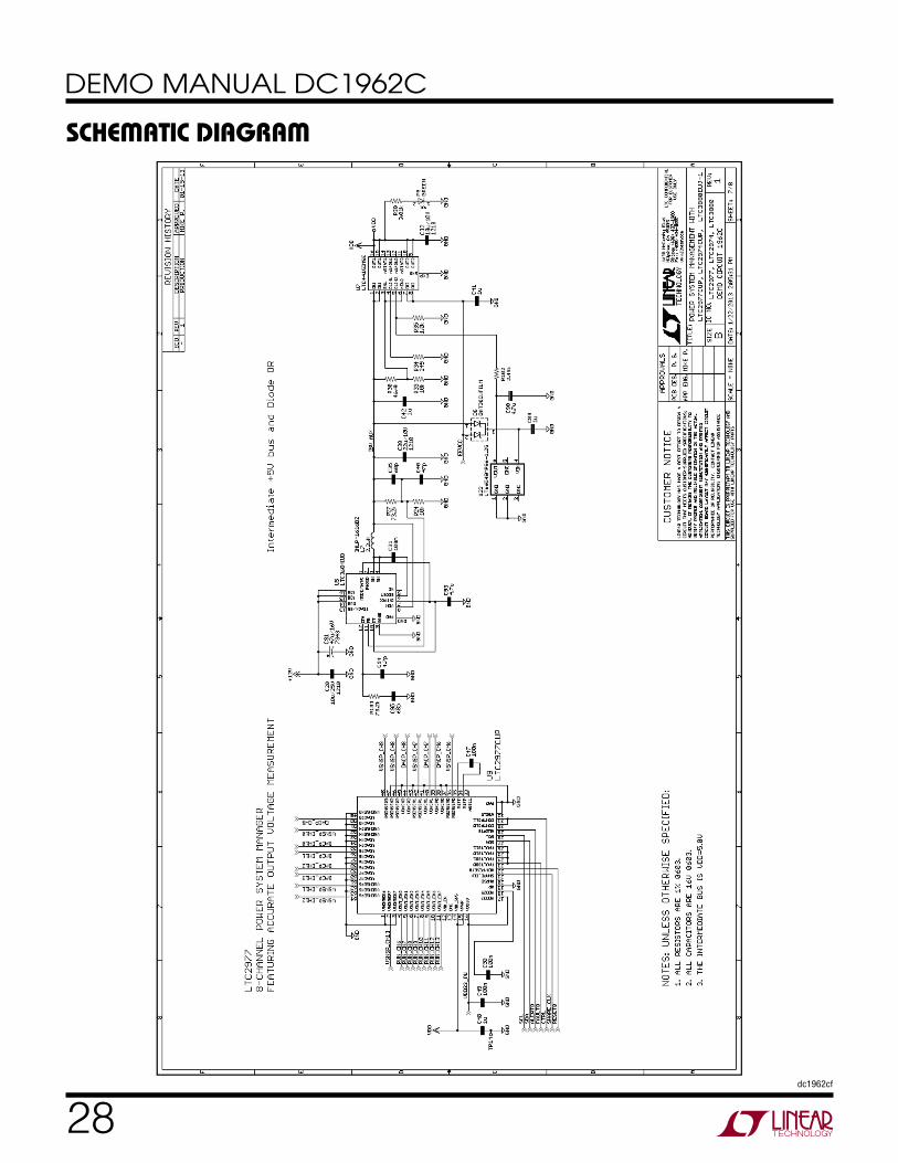
schematic DiaGram

23dc1962cf
DEMO MANUAL DC1962C
schematic DiaGram

24dc1962cf
DEMO MANUAL DC1962C
schematic DiaGram

25dc1962cf
DEMO MANUAL DC1962C
schematic DiaGram

26dc1962cf
DEMO MANUAL DC1962C
schematic DiaGram

27dc1962cf
DEMO MANUAL DC1962C
schematic DiaGram
28dc1962cf
DEMO MANUAL DC1962C
schematic DiaGram

29dc1962cf
DEMO MANUAL DC1962C
Information furnished by Linear Technology Corporation is believed to be accurate and reliable. However, no responsibility is assumed for its use. Linear Technology Corporation makes no representa-tion that the interconnection of its circuits as described herein will not infringe on existing patent rights.
schematic DiaGram
30dc1962cf
DEMO MANUAL DC1962C
Linear Technology Corporation1630 McCarthy Blvd., Milpitas, CA 95035-7417 (408) 432-1900 ● FAX: (408) 434-0507 ● www.linear.com LINEAR TECHNOLOGY CORPORATION 2013
LT 0413 • PRINTED IN USA
DEMONSTRATION BOARD IMPORTANT NOTICE
Linear Technology Corporation (LTC) provides the enclosed product(s) under the following AS IS conditions:
This demonstration board (DEMO BOARD) kit being sold or provided by Linear Technology is intended for use for ENGINEERING DEVELOPMENT OR EVALUATION PURPOSES ONLY and is not provided by LTC for commercial use. As such, the DEMO BOARD herein may not be complete in terms of required design-, marketing-, and/or manufacturing-related protective considerations, including but not limited to product safety measures typically found in finished commercial goods. As a prototype, this product does not fall within the scope of the European Union directive on electromagnetic compatibility and therefore may or may not meet the technical requirements of the directive, or other regulations.
If this evaluation kit does not meet the specifications recited in the DEMO BOARD manual the kit may be returned within 30 days from the date of delivery for a full refund. THE FOREGOING WARRANTY IS THE EXCLUSIVE WARRANTY MADE BY THE SELLER TO BUYER AND IS IN LIEU OF ALL OTHER WARRANTIES, EXPRESSED, IMPLIED, OR STATUTORY, INCLUDING ANY WARRANTY OF MERCHANTABILITY OR FITNESS FOR ANY PARTICULAR PURPOSE. EXCEPT TO THE EXTENT OF THIS INDEMNITY, NEITHER PARTY SHALL BE LIABLE TO THE OTHER FOR ANY INDIRECT, SPECIAL, INCIDENTAL, OR CONSEQUENTIAL DAMAGES.
The user assumes all responsibility and liability for proper and safe handling of the goods. Further, the user releases LTC from all claims arising from the handling or use of the goods. Due to the open construction of the product, it is the user’s responsibility to take any and all appropriate precautions with regard to electrostatic discharge. Also be aware that the products herein may not be regulatory compliant or agency certified (FCC, UL, CE, etc.).
No License is granted under any patent right or other intellectual property whatsoever. LTC assumes no liability for applications assistance, customer product design, software performance, or infringement of patents or any other intellectual property rights of any kind.
LTC currently services a variety of customers for products around the world, and therefore this transaction is not exclusive.
Please read the DEMO BOARD manual prior to handling the product. Persons handling this product must have electronics training and observe good laboratory practice standards. Common sense is encouraged.
This notice contains important safety information about temperatures and voltages. For further safety concerns, please contact a LTC applica-tion engineer.
Mailing Address:
Linear Technology
1630 McCarthy Blvd.
Milpitas, CA 95035
Copyright © 2004, Linear Technology Corporation