emc ite test report - · pdf fileprodukte products prüfbericht - nr.: test report no.:...
TRANSCRIPT


Produkte Products
Prüfbericht - Nr.: Test Report No.:
19645746 001
Seite 2 von 32 Page 2 of 32
TEST SUMMARY
5.1.1 RADIATED RADIO-FREQUENCY ELECTROMAGNETIC FIELDS (RADIATED
SUSCEPTIBILITY) RESULT: PASS
5.1.2 CONDUCTED DISTURBANCES INDUCED BY RADIO-FREQUENCY FIELDS (CONDUCTED
SUSCEPTIBILITY) RESULT: PASS
5.1.3 CONDUCTED IMMUNITY TO LOW FREQUENCY FIELDS RESULT: PASS
5.1.4 POWER FREQUENCY MAGNETIC FIELDS RESULT: PASS
5.2.1 ELECTRICAL FAST TRANSIENTS AND BURSTS RESULT: PASS
5.2.2 SURGES RESULT: PASS
5.2.3 ELECTROSTATIC DISCHARGES RESULT: PASS
5.3.1 VOLTAGE DIPS RESULT: PASS
5.3.2 VOLTAGE INTERRUPTIONS RESULT: PASS

Produkte Products
Prüfbericht - Nr.: Test Report No.:
19645746 001
Seite 3 von 32 Page 3 of 32
Contents
1. GENERAL REMARKS ............................................................................................... 4
1.1 COMPLEMENTARY MATERIALS ................................................................................. 4
2. TEST SITES ............................................................................................................ 5
2.1 TEST FACILITIES ..................................................................................................... 5
2.2 LIST OF TEST AND MEASUREMENT INSTRUMENTS ...................................................... 5
3. GENERAL PRODUCT INFORMATION ........................................................................... 6
3.1 PRODUCT FUNCTION AND INTENDED USE .................................................................. 6
3.2 RATINGS AND SYSTEM DETAILS ............................................................................... 6
3.3 NOISE GENERATING AND NOISE SUPPRESSING PARTS .............................................. 6
3.4 SUBMITTED DOCUMENTS ......................................................................................... 6
4. TEST SET-UP AND OPERATION MODES ..................................................................... 7
4.1 PRINCIPLE OF CONFIGURATION SELECTION ............................................................... 7
4.2 OPERATION MODES ................................................................................................ 7
4.3 PHYSICAL CONFIGURATION FOR TESTING ................................................................. 7
4.4 TEST OPERATION & TEST SOFTWARE ...................................................................... 7
4.5 SPECIAL ACCESSORIES AND AUXILIARY EQUIPMENT ................................................. 7
4.6 COUNTERMEASURES TO ACHIEVE EMC COMPLIANCE ................................................ 7
5 . TEST RESULTS I M M U N I T Y ............................................................................. 8
5.1 CONTINUOUS DISTURBANCES .................................................................................. 8 5.1.1 Radiated Radio-frequency Electromagnetic Fields (Radiated Susceptibility) .............................. 8 5.1.2 Conducted Disturbances induced by Radio-frequency Fields (Conducted Susceptibility) ........ 10 5.1.3 Conducted Immunity to low frequency Fields ............................................................................ 12 5.1.4 Power Frequency Magnetic Fields ............................................................................................. 13
5.2 TRANSIENT DISTURBANCES ................................................................................... 14 5.2.1 Electrical Fast Transients and Bursts ........................................................................................ 14 5.2.2 Surges ........................................................................................................................................ 16 5.2.3 Electrostatic Discharges ............................................................................................................ 18
5.3 POWER SUPPLY ALTERATIONS .............................................................................. 20 5.3.1 Voltage Dips ............................................................................................................................... 20 5.3.2 Voltage Interruptions .................................................................................................................. 22
6. PHOTOGRAPHS OF THE TEST SET-UP ..................................................................... 23
7. LIST OF TABLES .................................................................................................... 31
8. LIST OF PHOTOGRAPHS ......................................................................................... 31

Produkte Products
Prüfbericht - Nr.: Test Report No.:
19645746 001
Seite 4 von 32 Page 4 of 32
1. General Remarks
According to the product specification testing levels & performance criteria were considered according to 62040-2.
Interface cable in EUT Interfaces Max. cable length Cable Type
(Shielded/Un shielded)
Serial Cable 4.5m Unshielded
USB 1(On Unit) 5m Shielded
USB 2(On NMC) 5m Shielded
USB 3(On NMC) 5m Shielded
Universal I/O 1(On NMC) 4m Unshielded
Universal I/O 2(On NMC) 4m Unshielded
Network 1(On Unit) 15m Unshielded
Network 2(On NMC) 15m Unshielded
EPO(On Unit) 5m Unshielded
EUT does not support any other cable apart from the cables mentioned in the above table. UPS models listed below are identical to each other mechanically and electrically. The only differences between these models are the installation practices and the addition of network management card. Please find below the differences between the models. External battery packs SRT48RMBP and SRT48BP are accessories to the UPS and are identical to each other
Product SKU Product Description
SRT1500XLA APC Smart-UPS SRT 1500VA 120V
SRT1500RMXLA APC Smart-UPS SRT 1500VA RM 120V
SRT1500RMXLA-NC APC Smart-UPS SRT 1500VA RM 120V Network Card
SRT1000XLA APC Smart-UPS SRT 1000VA 120V
SRT1000RMXLA APC Smart-UPS SRT 1000VA RM 120V
SRT1000RMXLA-NC APC Smart-UPS SRT 1000VA RM 120V Network Card
SRT48RMBP APC Smart-UPS SRT 48V 1.5 kVA and 1 kVA RM Battery Pack
SRT48BP APC Smart-UPS SRT 48V 1.5 kVA and 1 kVA Battery Pack
1.1 Complementary Materials
No attachments along this test report.

Produkte Products
Prüfbericht - Nr.: Test Report No.:
19645746 001
Seite 5 von 32 Page 5 of 32
2. Test Sites
2.1 Test Facilities
1) TÜV Rheinland (India) Pvt. Ltd. Plot No. 108, West Wing, Electronic City Phase 1 Hosur Road
Bangalore – 560 100. Website: www.tuv.com This test site is in accordance with CISPR 16 for measurement of radio interference. The used test equipment is in accordance with CISPR 16 for measurement of radio interference. The tests have been conducted by a TÜV Rheinland testing engineer.
2.2 List of Test and Measurement Instruments
Table 1: List of Test and Measurement Equipment
Kind of Equipment Manufacturer Model Name Serial Number Calibrated
until
For Radiated Susceptibility (RS)
Signal Generator Agilent E8257D-ATO-1895 MY51110514 10-Jan-2018
RF Power Amplifier MILMEGA 80RF1000-500 1045085 NA
RF Power Amplifier MILMEGA AS0102-200 1045089 NA
RF Power Amplifier MILMEGA AS1860-100 1045088 NA
Stacked Double Logged Periodic Antenna
Schwarzbeck STLP9128D 9128D037 NA
Power Meter Agilent N1914A MY50001234 02-Feb-2018
For Conducted Susceptibility (CS)
Conducted Immunity Test System
EM Test CWS 500D V0732102786 29-Feb-2017
Attenuator EM Test ATT6/75 1009-19 26-Feb-2017
EM Clamp EM Test EM 101 35861 26-Feb-2017
CDN EM Test M5 0310-01 25-Feb-2017
Signal Line CDN EM Test CDN-T8-RJ45 1007-67 29-Feb-2017
For Low Frequency Conducted Disturbance
Arbitrary Waveform Generator
Agilent 33220A MY44053559 07-Nov-2017
Audio Isolation transformer
Solar Electronics
6220-1A - NA

Produkte Products
Prüfbericht - Nr.: Test Report No.:
19645746 001
Seite 6 von 32 Page 6 of 32
Kind of Equipment Manufacturer Model Name Serial Number Calibrated
until
For Electrical Fast Transients (EFT) & Surge
EMC Immunity Test System
EMC Partner TRA3000 1515 13-Jul-2017
Capacitive Coupling Clamp
EMC Partner CN-EFT1000 679 22-Jul-2017
Telecom Line CDN ThermoElectron CM-TELCD 0603297 NA
For Electrostatic Discharges (ESD)
ESD Simulator Noiseken ESS 2002 EX ESS0999547 20-Sep-2017
For Power Frequency Magnetic Field
Magnetic Field immunity Loop
FCC F-1000-4-8/9/10-L-
1M 05013 05-Nov-2017
Earth Bond Tester Lumetronics EC-12 150903 21-Nov-2016
For Voltage Dips & Interruptions
EMC Tester EMC Partner TRA3000 1515 13-Jul-2017
3. General Product Information
3.1 Product Function and Intended Use
The EUT is a Uniterruptible Power Supply which provides reliable power to connected load and when there is power failure.
3.2 Ratings and System Details
System Input Voltage: AC 120V Frequency: 60Hz Input Current: Max 16A Protection Class: I
3.3 Noise Generating and Noise Suppressing Parts
Noise generating & suppressing parts are integral part of the design
3.4 Submitted Documents
1. User Manual

Produkte Products
Prüfbericht - Nr.: Test Report No.:
19645746 001
Seite 7 von 32 Page 7 of 32
4. Test Set-up and Operation Modes
4.1 Principle of Configuration Selection
Immunity: The equipment under test (EUT) was configured to have its highest possible susceptibility against the tested phenomena. The test modes were adapted accordingly in reference to the instructions for use.
4.2 Operation Modes
The operation modes used for testing are:
A. EUT to be operated in Normal Operation @ 120V 60Hz Online Mode
4.3 Physical Configuration for Testing
For more details, refer to section: Photographs of the Test Set-Up.
4.4 Test Operation & Test Software
During testing in Online mode, EUT was powered with an input voltage of 120 VAC/60Hz. EUT was loaded with a bulb and resistive load of 1350W.
Application software: Microlink simulator Software version: ulSim 4.0.0.6 Firmware version: UPSa5.1
4.5 Special Accessories and Auxiliary Equipment
Item Manufacturer Type
PC DELL -
Power Supply Chroma -
Load Avtron -
4.6 Countermeasures to achieve EMC Compliance
No additional measures were employed to achieve compliance.

Produkte Products
Prüfbericht - Nr.: Test Report No.:
19645746 001
Seite 8 von 32 Page 8 of 32
5 . Test Results I M M U N I T Y
5.1 Continuous Disturbances
5.1.1 Radiated Radio-frequency Electromagnetic Fields (Radiated Susceptibility)
RESULT: PASS
Date of testing: 27-Oct-2016
Ambient temperature: 25C Relative humidity: 59% Atmospheric pressure: 91kPa Test procedure: IEC 61000-4-3:2010 Frequency range: 80-6000MHz Test level: 3 (10V/m) (unmodulated, rms.) Modulation: 80% AM, 1kHz Step size: 1% Dwell time: 2.85s Supply voltage during testing: AC 120V Test mode applied: A Performance criterion: A Met criterion: A Note:
The EUT was placed on a non-conductive table 80cm above the floor in an anechoic chamber. Each face of the EUT and the attached cables were exposed in sequence to the electromagnetic field produced by a transmitting antenna. For each EUT orientation, the frequency was swept from 80MHz to 6GHz. The EUT operation was monitored during the test. It was verified that its response to the external disturbance remains within the performance specifications.

Produkte Products
Prüfbericht - Nr.: Test Report No.:
19645746 001
Seite 9 von 32 Page 9 of 32
Table 2: Immunity against Radiated Radio-frequency Electromagnetic Fields
Field Polarization
Side of EUT
Frequency Result Remark
Vertical Front 80-6000 MHz Pass EUT operated as intended, no degradation of function.
Vertical Rear 80-6000 MHz Pass EUT operated as intended, no degradation of function.
Vertical Left 80-6000 MHz Pass EUT operated as intended, no degradation of function.
Vertical Right 80-6000 MHz Pass EUT operated as intended, no degradation of function.
Horizontal Front 80-6000 MHz Pass EUT operated as intended, no degradation of function.
Horizontal Rear 80-6000 MHz Pass EUT operated as intended, no degradation of function.
Horizontal Left 80-6000 MHz Pass EUT operated as intended, no degradation of function.
Horizontal Right 80-6000 MHz Pass EUT operated as intended, no degradation of function.

Produkte Products
Prüfbericht - Nr.: Test Report No.:
19645746 001
Seite 10 von 32 Page 10 of 32
5.1.2 Conducted Disturbances induced by Radio-frequency Fields (Conducted Susceptibility)
RESULT: PASS
Date of testing: 07-Nov-2016
Ambient temperature: 24C Relative humidity: 56% Atmospheric pressure: 91kPa Test procedure: IEC 61000-4-6:2013 Severity level: 3 (10V) for AC power ports (unmodulated, rms.) 3 (10V) for signal ports (unmodulated, rms.)
Source impedance: 150 Frequency range: 150kHz - 80MHz Modulation: 80% AM, 1kHz Sweep mode: Automatic Step size: 1% Dwell time: 2.85s Supply voltage during testing: AC 120V Test mode applied: A Performance criterion: A Met criterion: A Note:
The EUT and its associated accessories were placed on a non-conductive support 10cm above a reference ground plane. Radio-frequency conducted disturbances were injected into the EUT cables via a CDN or a coupling clamp. For each cable selected for testing, the frequency was swept from 150kHz to 80MHz. The EUT operation was monitored during the test. It was verified that its response to the external disturbance remains within the performance specifications.

Produkte Products
Prüfbericht - Nr.: Test Report No.:
19645746 001
Seite 11 von 32 Page 11 of 32
Table 3: Immunity against Conducted Disturbances induced by Radio-frequency Fields
Coupling Port Coupling Method: Result Remark
AC Input: Line (L), Neutral(N),PE
CDN M-5 PASS EUT operated as intended, no degradation of function.
Output Power: Line (L), Neutral(N),PE
CDN M-5 PASS EUT operated as intended, no degradation of function.
EPO Cable EM Clamp PASS EUT operated as intended, no degradation of function.
Serial Cable EM Clamp PASS EUT operated as intended, no degradation of function.
USB Cable EM Clamp PASS EUT operated as intended, no degradation of function.
Universal I/O 1 EM Clamp PASS EUT operated as intended, no degradation of function.
Universal I/O 2 EM Clamp PASS EUT operated as intended, no degradation of function.
Ethernet (NMC) Cable CDN-T8-RJ45 PASS EUT operated as intended, no degradation of function.
Ethernet (Unit) Cable CDN-T8-RJ45 PASS EUT operated as intended, no degradation of function.

Produkte Products
Prüfbericht - Nr.: Test Report No.:
19645746 001
Seite 12 von 32 Page 12 of 32
5.1.3 Conducted Immunity to low frequency Fields
RESULT: PASS
Date of testing: 21-Nov-2016
Ambient temperature: 25C Relative humidity: 57% Atmospheric pressure: 91kPa Test procedure: IEC 61000-2-2:2002 Severity level: 3 (10V) for AC power ports (unmodulated, rms.) Frequency range: 140Hz - 360Hz Sweep mode: Automatic Step size: 1% Dwell time: 3.00s Supply voltage during testing: AC 120V Test mode applied: A Performance criterion: A Met criterion: A Note:
The EUT and its associated accessories were placed on a non-conductive support 10cm above a reference ground plane. Low-frequency conducted disturbances were injected into the EUT cables. For each cable selected for testing, the frequency was swept from 140Hz to 360Hz. The EUT operation was monitored during the test. It was verified that its response to the external disturbance remains within the performance specifications.
Table 4: Immunity against Conducted Disturbances induced by Low-frequency Fields
Coupling Port Coupling Method: Result Remark
AC Input: Line (L), (N), PE
Series Injection PASS EUT operated as intended, no degradation of function.

Produkte Products
Prüfbericht - Nr.: Test Report No.:
19645746 001
Seite 13 von 32 Page 13 of 32
5.1.4 Power Frequency Magnetic Fields
RESULT: PASS
Date of testing: 10-Nov-2016
Ambient temperature: 24C Relative humidity: 54% Atmospheric pressure: 91kPa Test procedure: IEC 61000-4-8:2009 Severity level: 4 (30A/m) Frequency: 60Hz Supply voltage during testing: AC 120V Test mode applied: A Compliance criteria: B Met criterion: A
Table 5: Immunity against Power Frequency Magnetic Field:
Field Polarization Coil Orientation Result Remark
Horizontal Parallel to front side. Pass EUT operated as intended, no degradation of function.
Horizontal Perpendicular to front side. Pass EUT operated as intended, no degradation of function.
Vertical Horizontal to front side. Pass EUT operated as intended, no degradation of function.

Produkte Products
Prüfbericht - Nr.: Test Report No.:
19645746 001
Seite 14 von 32 Page 14 of 32
5.2 Transient Disturbances
5.2.1 Electrical Fast Transients and Bursts
RESULT: PASS
Date of testing: 08-Nov-2016
Ambient temperature: 26C Relative humidity: 55% Atmospheric pressure: 91kPa Test procedure: IEC 61000-4-4:2012 Severity level: 3 (±2kV) AC power ports 4 (±2kV) signal ports Repetition rate: 5kHz
Test duration: 60s Supply voltage during testing: AC 120V Test mode applied: A Performance criterion: B Met criterion: A Note:
The EUT and its attached cables were placed on a non-conductive support 10cm above a reference ground plane. Electrical fast transients and bursts were injected into each cable selected for testing via a CDN. The EUT operation was monitored during the test.

Produkte Products
Prüfbericht - Nr.: Test Report No.:
19645746 001
Seite 15 von 32 Page 15 of 32
Table 6: Immunity against Electrical Fast Transients and Bursts:
Coupling Method: CDN Injection
Coupling Port Test Voltage / Result Remark
AC Input: L1 (L), L2 (N) PE (or reference ground)
±500V PASS ±1000V PASS ±2000V PASS
EUT operated as intended, no degradation of function.
AC Output: L1 (L), L2 (N) PE (or reference ground)
±500V PASS ±1000V PASS ±2000V PASS
EUT operated as intended, no degradation of function.
Table 7: Immunity against Electrical Fast Transients (EFT), on Signal Ports
Coupling Method: Capacitive Clamp
Coupling Port Test Voltage / Result Remark
EPO Cable ±500V PASS ±1000V PASS ±2000V PASS
EUT operated as intended, no degradation of function.
Serial Cable ±500V PASS ±1000V PASS ±2000V PASS
EUT operated as intended, no degradation of function.
USB Cable ±500V PASS ±1000V PASS ±2000V PASS
EUT operated as intended, no degradation of function.
Universal I/O 1 ±500V PASS ±1000V PASS ±2000V PASS
EUT operated as intended, no degradation of function.
Universal I/O 2 ±500V PASS ±1000V PASS ±2000V PASS
EUT operated as intended, no degradation of function.
Ethernet (NMC) Cable ±500V PASS ±1000V PASS ±2000V PASS
EUT operated as intended, no degradation of function.
Ethernet (Unit) Cable ±500V PASS ±1000V PASS ±2000V PASS
EUT operated as intended, no degradation of function.

Produkte Products
Prüfbericht - Nr.: Test Report No.:
19645746 001
Seite 16 von 32 Page 16 of 32
5.2.2 Surges
RESULT: PASS
Date of testing: 08-Nov-2016
Ambient temperature: 25C Relative humidity: 57% Atmospheric pressure: 91kPa Test procedure: IEC 61000-4-5:2014 Severity level: 3 (±2kV) for AC power ports 2 (±1kV) for Signal Ports
Source impedance: 2, 12
Test voltages: 500V, 1000V, 2000V
Coupling phases: /2, , 3/2 (90°, 180°, 270°) Number of surges: 5 (for each parameter combination) Time between pulses: ≤ 60s Supply voltage during testing: AC 120V Test mode applied: A Performance criterion: B Met criterion: A Note:
The EUT and its attached cables were placed on a non-conductive support 80cm above a reference ground plane. Surges were injected into each cable selected for testing via a CDN. The EUT operation was monitored during the test.

Produkte Products
Prüfbericht - Nr.: Test Report No.:
19645746 001
Seite 17 von 32 Page 17 of 32
Table 8: Surge Immunity Tests, on AC Power port
Coupling Port Test
Voltage Coupling
Phase Result Remark
Input port
Input Port: L1 (L) - L2 (N) Differential (Line to Neutral)
500V
1000V
/2
3/2
Pass EUT operated as intended, no degradation of function.
Input Port: L1 (L) – PE Common (Line to Ground)
500V
1000V
2000V
/2
3/2
Pass EUT operated as intended, no degradation of function.
Input Port: L2 (N) - PE Common (Neutral to Ground)
500V
1000V
2000V
/2
3/2
Pass EUT operated as intended, no degradation of function.
Output port
Output Port: L1 (L) - L2 (N) Differential (Line to Neutral)
500V
1000V
/2
3/2
Pass EUT operated as intended, no degradation of function.
Output Port: L1 (L) – PE Common (Line to Ground)
500V
1000V
2000V
/2
3/2
Pass EUT operated as intended, no degradation of function.
Output Port: L2 (N) - PE Common (Neutral to Ground)
500V
1000V
2000V
/2
3/2
Pass EUT operated as intended, no degradation of function.
Table 9: Surge Immunity Tests, on Signal Port
Coupling Port Coupling
Mode Test
Voltage Result Remark
Ethernet (NMC) Cable CM-TELCD 500V
±1000V Pass
EUT operated as intended, no degradation of function.
Ethernet (Unit) Cable CM-TELCD 500V
±1000V Pass
EUT operated as intended, no degradation of function.

Produkte Products
Prüfbericht - Nr.: Test Report No.:
19645746 001
Seite 18 von 32 Page 18 of 32
5.2.3 Electrostatic Discharges
RESULT: PASS
Date of testing: 10-Nov-2016
Ambient temperature: 25C Relative humidity: 46% Atmospheric pressure: 91kPa Test procedure: IEC 61000-4-2:2008 Severity level: 2 (±4kV) (contact discharge)
3 (±8kV) (air discharge) Number of discharges per test point: ≥ 10 for each test voltage and polarity Supply voltage during testing: AC 120V Test mode applied: A Performance criterion: B Met criterion: B Note: The EUT was placed on a non-conductive support 80cm above a ground reference plane (GRP). The EUT and its attached cables were isolated from the GRP by a thin insulating support of 0.5mm thickness. Electrostatic discharges were applied using an ESD gun directly (via contact or air discharges). The EUT operation was monitored during the test.

Produkte Products
Prüfbericht - Nr.: Test Report No.:
19645746 001
Seite 19 von 32 Page 19 of 32
Table 10: Immunity against Electrostatic Discharges, both Polarities
Discharge Points
Type of Discharge
Test Voltages Result Remark
Front Enclosure:
Contact ±2, ±4kV Pass
EUT operated as intended, no degradation of function.
VCP ±2, ±4kV Pass
EUT operated as intended, no degradation of function.
HCP ±2, ±4kV Pass
During test at ±2kV display went to sleep mode & recovered back after the test.
Air ±2, ±4, ±8kV Pass
EUT operated as intended, no degradation of function.
Left Enclosure:
Contact ±2, ±4kV Pass
EUT operated as intended, no degradation of function.
VCP, HCP ±2, ±4kV Pass
EUT operated as intended, no degradation of function.
Right Enclosure:
Contact ±2, ±4kV Pass
EUT operated as intended, no degradation of function.
VCP, HCP ±2, ±4kV Pass
EUT operated as intended, no degradation of function.
Rear Enclosure:
Contact ±2, ±4kV Pass
EUT operated as intended, no degradation of function.
VCP, HCP ±2, ±4kV Pass
EUT operated as intended, no degradation of function.
Top Enclosure:
Contact ±2, ±4kV Pass
EUT operated as intended, no degradation of function.
Cables:
Air ±2, ±4, ±8kV Pass
EUT operated as intended, no degradation of function.
Display:
Air ±2, ±4, ±8kV Pass
During test at -4kV, ±8kV display went to sleep mode & recovered back after the test.

Produkte Products
Prüfbericht - Nr.: Test Report No.:
19645746 001
Seite 20 von 32 Page 20 of 32
5.3 Power Supply Alterations
5.3.1 Voltage Dips
RESULT: PASS
Date of testing: 08-Nov-2016
Ambient temperature: 26C Relative humidity: 55% Atmospheric pressure: 91kPa Test procedure: IEC 61000-4-11:2004 Test parameters: >-95%, 0.5 periods, 8.3ms @ 60Hz Performance criterion: B Met criterion:A -100%, 1 cycle, 16.7ms @ 60Hz Performance criterion: B Met criterion:A
-60%, 12 cycles, 200ms @ 60Hz Performance criterion: B Met criterion:B
-30%, 30 cycles, 500ms @ 60Hz Performance criterion: B Met criterion:B
-20%, 300cycles, 5000ms @ 60Hz Performance criterion: B Met criterion:B Starting phases: 0° Number of voltage dips: 3 (for each parameter combination) Time between voltage dips: 60s Supply voltage during testing: 120V AC Test mode applied: A
Note:
The EUT was connected to a test generator. The specified series of voltage dips were applied in sequence at the AC mains input port of the EUT. The EUT operation was monitored during the test.

Produkte Products
Prüfbericht - Nr.: Test Report No.:
19645746 001
Seite 21 von 32 Page 21 of 32
Table 11: Immunity against Voltage Dips, AC 120V, 60Hz Input Voltage
Voltage Reduction
Applied Voltage
Duration Starting
Phase [rad] Result Remark
100% 0V 8.3ms 0 Pass EUT operated as intended, no degradation of function.
100% 0V 16.7ms 0 Pass EUT operated as intended, no degradation of function.
60% 48V 200ms 0 Pass EUT changed to Battery mode & recovered back.
30% 84V 500ms 0 Pass EUT changed to Battery mode & recovered back
20% 96V 5000ms 0 Pass EUT changed to Battery mode & recovered back
Produkte Products
Prüfbericht - Nr.: Test Report No.:
19645746 001
Seite 22 von 32 Page 22 of 32
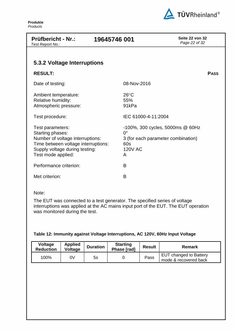
5.3.2 Voltage Interruptions
RESULT: PASS
Date of testing: 08-Nov-2016
Ambient temperature: 26C Relative humidity: 55% Atmospheric pressure: 91kPa Test procedure: IEC 61000-4-11:2004 Test parameters: -100%, 300 cycles, 5000ms @ 60Hz Starting phases: 0° Number of voltage interruptions: 3 (for each parameter combination) Time between voltage interruptions: 60s Supply voltage during testing: 120V AC Test mode applied: A Performance criterion: B Met criterion: B Note:
The EUT was connected to a test generator. The specified series of voltage interruptions was applied at the AC mains input port of the EUT. The EUT operation was monitored during the test.
Table 12: Immunity against Voltage Interruptions, AC 120V, 60Hz Input Voltage
Voltage Reduction
Applied Voltage
Duration Starting
Phase [rad] Result Remark
100% 0V 5s 0 Pass EUT changed to Battery mode & recovered back

Produkte Products
Prüfbericht - Nr.: Test Report No.:
19645746 001
Seite 23 von 32 Page 23 of 32
6. Photographs of the Test Set-Up
Photograph 1: Set-up for Radiated Susceptibility, Vertical Polarization

Produkte Products
Prüfbericht - Nr.: Test Report No.:
19645746 001
Seite 24 von 32 Page 24 of 32
Photograph 2: Set-up for Radiated Susceptibility, Horizontal Polarization

Produkte Products
Prüfbericht - Nr.: Test Report No.:
19645746 001
Seite 25 von 32 Page 25 of 32
Photograph 3: Set-up for Conducted Susceptibility, CDN Injection Method, AC Input and Output Power Port
Photograph 4: Set-up for Conducted Susceptibility, EM clamp Method, Signal Port

Produkte Products
Prüfbericht - Nr.: Test Report No.:
19645746 001
Seite 26 von 32 Page 26 of 32
Photograph 5: Set-up for Low Frequency Conducted Immunity
Photograph 6: Set-up for Electrical Fast Transients and Bursts, on AC Input and Output Power Ports

Produkte Products
Prüfbericht - Nr.: Test Report No.:
19645746 001
Seite 27 von 32 Page 27 of 32
Photograph 7: Set-up for Electrical Fast Transients and Bursts, on Signal Ports
Photograph 8: Set-up for Power Frequency Magnetic Field

Produkte Products
Prüfbericht - Nr.: Test Report No.:
19645746 001
Seite 28 von 32 Page 28 of 32
Photograph 9: Set-up for Surges, on AC Input and Output Power Ports

Produkte Products
Prüfbericht - Nr.: Test Report No.:
19645746 001
Seite 29 von 32 Page 29 of 32
Photograph 10: Set-up for Surges, on Signal Ports
Photograph 11: Set-up for Electrostatic Discharges, Contact Discharges

Produkte Products
Prüfbericht - Nr.: Test Report No.:
19645746 001
Seite 30 von 32 Page 30 of 32
Photograph 12: Set-up for Electrostatic Discharges, Air Discharges
Photograph 13: Set-up for Electrostatic Discharges, VCP

Produkte Products
Prüfbericht - Nr.: Test Report No.:
19645746 001
Seite 31 von 32 Page 31 of 32
Photograph 14: Set-up for Electrostatic Discharges, HCP
7. List of Tables Table 1: List of Test and Measurement Equipment ...................................................................................... 5 Table 2: Immunity against Radiated Radio-frequency Electromagnetic Fields ............................................ 9 Table 3: Immunity against Conducted Disturbances induced by Radio-frequency Fields .......................... 11 Table 4: Immunity against Conducted Disturbances induced by Low-frequency Fields............................. 12 Table 5: Immunity against Power Frequency Magnetic Field: .................................................................... 13 Table 6: Immunity against Electrical Fast Transients and Bursts: .............................................................. 15 Table 7: Immunity against Electrical Fast Transients (EFT), on Signal Ports ............................................. 15 Table 8: Surge Immunity Tests, on AC Power port ..................................................................................... 17 Table 9: Surge Immunity Tests, on Signal Port ........................................................................................... 17 Table 10: Immunity against Electrostatic Discharges, both Polarities ........................................................ 19 Table 11: Immunity against Voltage Dips, AC 120V, 60Hz Input Voltage .................................................. 21 Table 12: Immunity against Voltage Interruptions, AC 120V, 60Hz Input Voltage ..................................... 22
8. List of Photographs Photograph 1: Set-up for Radiated Susceptibility, Vertical Polarization ..................................................... 23 Photograph 2: Set-up for Radiated Susceptibility, Horizontal Polarization ................................................. 24 Photograph 3: Set-up for Conducted Susceptibility, CDN Injection Method, AC Input and Output Power Port .............................................................................................................................................................. 25 Photograph 4: Set-up for Conducted Susceptibility, EM clamp Method, Signal Port ................................. 25 Photograph 5: Set-up for Low Frequency Conducted Immunity ................................................................. 26 Photograph 6: Set-up for Electrical Fast Transients and Bursts, on AC Input and Output Power Ports .... 26 Photograph 7: Set-up for Electrical Fast Transients and Bursts, on Signal Ports ...................................... 27 Photograph 8: Set-up for Power Frequency Magnetic Field ....................................................................... 27 Photograph 9: Set-up for Surges, on AC Input and Output Power Ports .................................................... 28

Produkte Products
Prüfbericht - Nr.: Test Report No.:
19645746 001
Seite 32 von 32 Page 32 of 32
Photograph 10: Set-up for Surges, on Signal Ports .................................................................................... 29 Photograph 11: Set-up for Electrostatic Discharges, Contact Discharges.................................................. 29 Photograph 12: Set-up for Electrostatic Discharges, Air Discharges .......................................................... 30 Photograph 13: Set-up for Electrostatic Discharges, VCP .......................................................................... 30 Photograph 14: Set-up for Electrostatic Discharges, HCP ......................................................................... 31