electromagnetic, stress and thermal analysis of the
TRANSCRIPT
1
Electromagnetic, stress and thermal analysis of the
Superconducting Magnet
Yong Ren1*, Xiang Gao1*, 2
1 Institute of Plasma Physics, Hefei Institutes of Physical Science, Chinese Academy of Sciences, PO Box 1126, Hefei, Anhui, 230031,
People's Republic of China
2University of Science and Technology of China, Hefei, Anhui 230026, People’s Republic of China
*E-mail: [email protected] and [email protected]
Abstract—Within the framework of the National Special
Project for Magnetic Confined Nuclear Fusion Energy of China,
the design of a superconducting magnet project as a test facility
of the Nb3Sn coil or NbTi coil for the Chinese Fusion Engineering
Test Reactor (CFETR) has been carried out not only to estimate
the relevant conductor performance but also to implement a
background magnetic field for CFETR CS insert and toroidal
field (TF) insert coils. The superconducting magnet is composed
of two parts: the inner part with Nb3Sn cable-in-conduit
conductor (CICC) and the outer part with NbTi CICC. Both
parts are connected in series and powered by a single DC power
supply. The superconducting magnet can be cooled with
supercritical helium at inlet temperature of 4.5 K. The total
inductance and stored energy of the superconducting magnet are
about 0.278 H and 436.6 MJ at an operating current of 56 kA
respectively. An active quench protection circuit was adopted to
transfer the stored magnetic energy of the superconducting
magnet during a dump operation.
In this paper, the design of the superconducting magnet and
the main analysis results of the electromagnetic, structural and
thermal-hydraulic performance are described.
Keywords—Cable-in-conduit conductor (CICC), CFETR,
Quench, Superconducting magnet, Stress, Thermal-hydraulic
behavior.
I. INTRODUCTION
HINESE Fusion Engineering Test Reactor (CFETR) is
being designed to bridge the gaps between the ITER and
Demo in China [1-6]. The superconducting magnet for the
CFETR reactor consists of a CS coil with 6 modules, 8 PF
coils, 16 TF coils and a set of correction coils [6]. The CFETR
CS coil with Nb3Sn conductor will operate in pulsed mode.
The electromagnetic and thermal cyclic operation often results
in Nb3Sn CICC conductor performance degradation [7-19].
Generally, the qualification tests of the Nb3Sn CICC
conductor in electromagnetic and thermal cyclic operation
were performed to evaluate the relevant Nb3Sn CICC coil
performance [14-19]. Occasionally, the qualification tests of
the Nb3Sn CICC conductors with a long length in relevant
conditions of magnetic field, current density and mechanical
strain are of great importance for the fabrication of the large
scale superconducting magnet [20-33]. Therefore, a design
activity has been started to design a superconducting magnet
project not only to estimate the CFETR CS coil performance
but also to implement a background field superconducting
magnet for testing the CFETR CS insert and TF insert coils.
During the first stage, the main goals of the project are
composed of: 1) to obtain the maximum magnetic field of
above 12.5 T; 2) to simulate the relevant thermal-hydraulic
characteristics of the CFETR CS coil; 3) to test the sensitivity
of the current sharing temperature to electromagnetic and
thermal cyclic operation. During the second stage, the
superconducting magnet was used to test the CFETR CS insert
and TF insert coils as a background magnetic field
superconducting magnet during the manufacturing stage of the
CFETR magnets.
In this paper, the magnetic field, the strain of the Nb3Sn
cable and the stress of the jacket for the superconducting
magnet with a detailed 2-D finite element method were
analyzed. The temperature margin behavior of the
superconducting magnet was analyzed with the 1-D
GANDALF code [34]. The quench behavior of the
superconducting magnet was given with the adiabatic hot spot
temperature criterion and the 1-D GANDALF code.
II. DESIGN OF THE SUPERCONDUCTING MAGNET
The superconducting magnet is designed to provide a
maximum magnetic field of above 12.5 T. The
superconducting magnet should have enough inner space to
provide a background magnetic field for testing the long
superconducting samples such as CFETR CS insert and TF
insert coils. The Nb3Sn cable-in-conduit conductor (CICC)
and NbTi CICC are graded for reducing the cost of the
superconducting strands for the superconducting magnet. The
superconducting magnet, which has a cold bore of 1400 mm in
diameter, will produce about 12.6 T maximum magnetic field
at 56 kA. The total self-inductance and stored energy of the
superconducting magnet are about 0.278 H and 436.6 MJ
respectively. Table 1 lists the main parameters of the
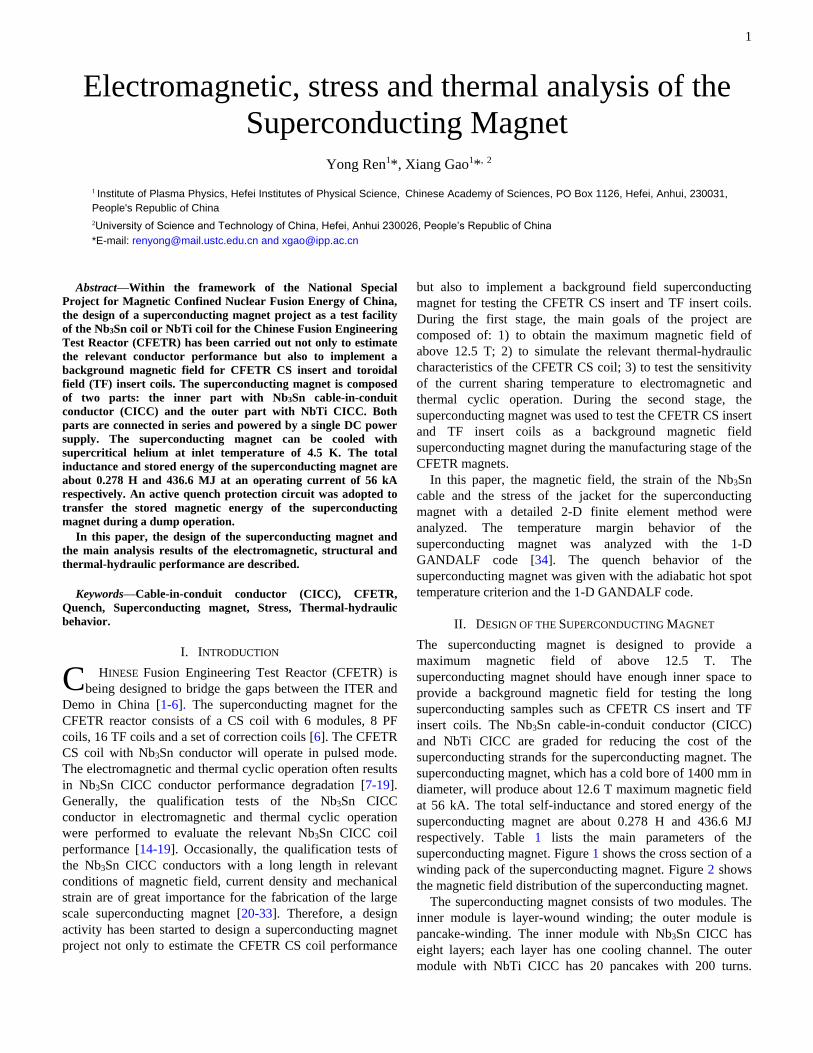
superconducting magnet. Figure 1 shows the cross section of a
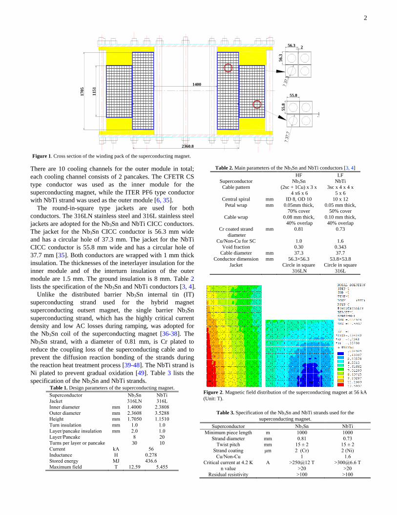
winding pack of the superconducting magnet. Figure 2 shows
the magnetic field distribution of the superconducting magnet.
The superconducting magnet consists of two modules. The
inner module is layer-wound winding; the outer module is
pancake-winding. The inner module with Nb3Sn CICC has
eight layers; each layer has one cooling channel. The outer
module with NbTi CICC has 20 pancakes with 200 turns.
C
2
There are 10 cooling channels for the outer module in total;
each cooling channel consists of 2 pancakes. The CFETR CS
type conductor was used as the inner module for the
superconducting magnet, while the ITER PF6 type conductor
with NbTi strand was used as the outer module [6, 35].
The round-in-square type jackets are used for both
conductors. The 316LN stainless steel and 316L stainless steel
jackets are adopted for the Nb3Sn and NbTi CICC conductors.
The jacket for the Nb3Sn CICC conductor is 56.3 mm wide
and has a circular hole of 37.3 mm. The jacket for the NbTi
CICC conductor is 55.8 mm wide and has a circular hole of
37.7 mm [35]. Both conductors are wrapped with 1 mm thick
insulation. The thicknesses of the ineterlayer insulation for the
inner module and of the interturn insulation of the outer
module are 1.5 mm. The ground insulation is 8 mm. Table 2
lists the specification of the Nb3Sn and NbTi conductors [3, 4].
Unlike the distributed barrier Nb3Sn internal tin (IT)
superconducting strand used for the hybrid magnet
superconducting outsert magnet, the single barrier Nb3Sn
superconducting strand, which has the highly critical current
density and low AC losses during ramping, was adopted for
the Nb3Sn coil of the superconducting magnet [36-38]. The
Nb3Sn strand, with a diameter of 0.81 mm, is Cr plated to
reduce the coupling loss of the superconducting cable and to
prevent the diffusion reaction bonding of the strands during
the reaction heat treatment process [39-48]. The NbTi strand is
Ni plated to prevent gradual oxidation [49]. Table 3 lists the
specification of the Nb3Sn and NbTi strands. Table 1. Design parameters of the superconducting magnet. Superconductor Nb3Sn NbTi
Jacket 316LN 316L
Inner diameter mm 1.4000 2.3808
Outer diameter mm 2.3608 3.5288
Height mm 1.7050 1.1510
Turn insulation mm 1.0 1.0
Layer/pancake insulation mm 2.0 1.0
Layer/Pancake 8 20
Turns per layer or pancake 30 10
Current kA 56
Inductance H 0.278
Stored energy MJ 436.6
Maximum field T 12.59 5.455
Table 2. Main parameters of the Nb3Sn and NbTi conductors [3, 4]
HF LF
Superconductor Nb3Sn NbTi
Cable pattern (2sc + 1Cu) x 3 x
4 x6 x 6
3sc x 4 x 4 x
5 x 6
Central spiral mm ID 8, OD 10 10 x 12
Petal wrap mm 0.05mm thick,
70% cover
0.05 mm thick,
50% cover
Cable wrap 0.08 mm thick,
40% overlap
0.10 mm thick,
40% overlap
Cr coated strand
diameter
mm 0.81 0.73
Cu/Non-Cu for SC 1.0 1.6
Void fraction 0.30 0.343
Cable diameter mm 37.3 37.7
Conductor dimension mm 56.3×56.3 53.8×53.8
Jacket Circle in square
316LN
Circle in square
316L
Figure 2. Magnetic field distribution of the superconducting magnet at 56 kA
(Unit: T).
Table 3. Specification of the Nb3Sn and NbTi strands used for the
superconducting magnet.
Superconductor Nb3Sn NbTi
Minimum piece length m 1000 1000
Strand diameter mm 0.81 0.73
Twist pitch mm 15 ± 2 15 ± 2
Strand coating μm 2 (Cr) 2 (Ni)
Cu/Non-Cu 1 1.6
Critical current at 4.2 K A >250@12 T >[email protected] T
n value >20 >20
Residual resistivity >100 >100
1400
2360.8
1151
56.3 2
56.3
?37.3
55.8
55.8
1
?37.7
1705
Figure 1. Cross section of the winding pack of the superconducting magnet.
3
ratio
Hysteresis loss per
strand unit volume
mJ/cm3 <[email protected] K
over a ± 3 T cycle
<[email protected] K over
a ± 1.5 T cycle
Effective filament
diameter
μm <30 <8
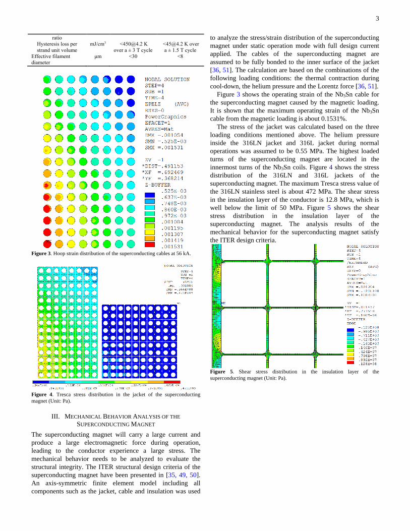
Figure 3. Hoop strain distribution of the superconducting cables at 56 kA.
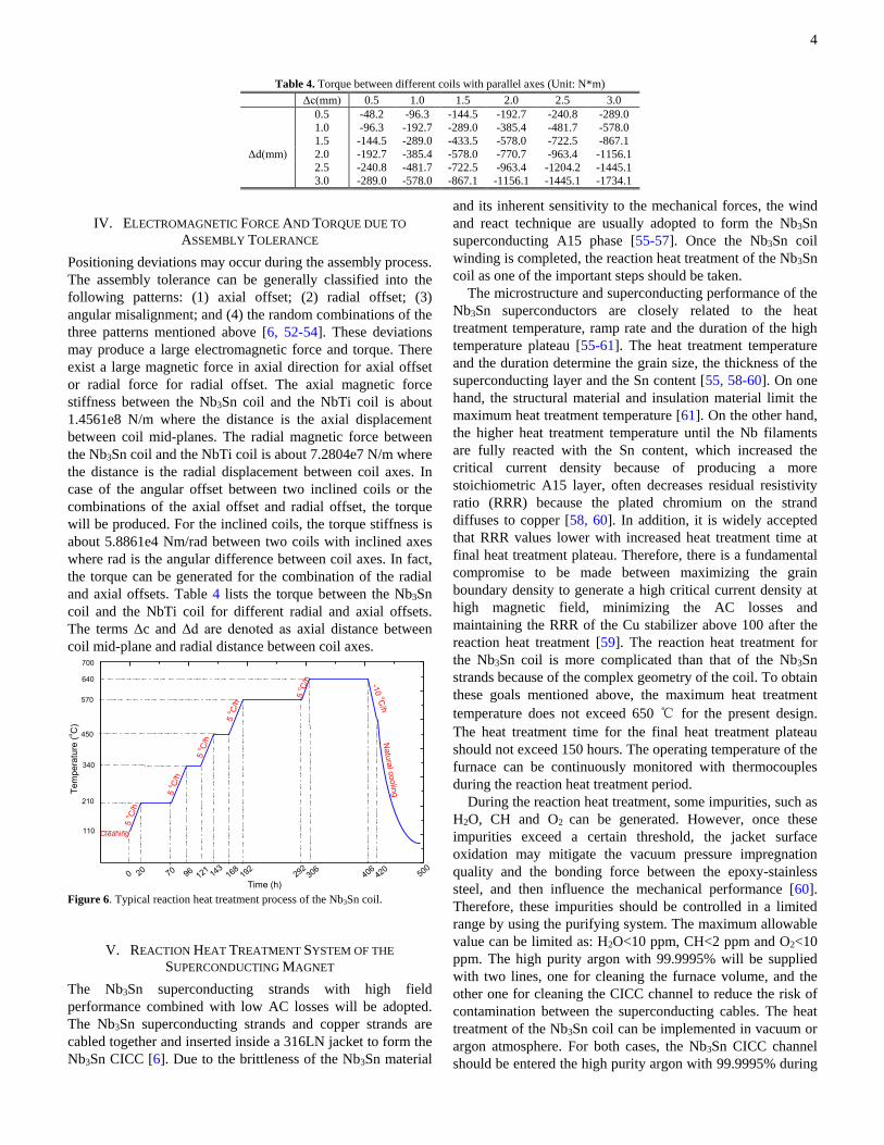
Figure 4. Tresca stress distribution in the jacket of the superconducting
magnet (Unit: Pa).
III. MECHANICAL BEHAVIOR ANALYSIS OF THE
SUPERCONDUCTING MAGNET
The superconducting magnet will carry a large current and
produce a large electromagnetic force during operation,
leading to the conductor experience a large stress. The
mechanical behavior needs to be analyzed to evaluate the
structural integrity. The ITER structural design criteria of the
superconducting magnet have been presented in [35, 49, 50].
An axis-symmetric finite element model including all
components such as the jacket, cable and insulation was used
to analyze the stress/strain distribution of the superconducting
magnet under static operation mode with full design current
applied. The cables of the superconducting magnet are
assumed to be fully bonded to the inner surface of the jacket
[36, 51]. The calculation are based on the combinations of the
following loading conditions: the thermal contraction during
cool-down, the helium pressure and the Lorentz force [36, 51].
Figure 3 shows the operating strain of the Nb3Sn cable for
the superconducting magnet caused by the magnetic loading.
It is shown that the maximum operating strain of the Nb3Sn
cable from the magnetic loading is about 0.1531%.
The stress of the jacket was calculated based on the three
loading conditions mentioned above. The helium pressure
inside the 316LN jacket and 316L jacket during normal
operations was assumed to be 0.55 MPa. The highest loaded
turns of the superconducting magnet are located in the
innermost turns of the Nb3Sn coils. Figure 4 shows the stress
distribution of the 316LN and 316L jackets of the
superconducting magnet. The maximum Tresca stress value of
the 316LN stainless steel is about 472 MPa. The shear stress
in the insulation layer of the conductor is 12.8 MPa, which is
well below the limit of 50 MPa. Figure 5 shows the shear
stress distribution in the insulation layer of the
superconducting magnet. The analysis results of the
mechanical behavior for the superconducting magnet satisfy
the ITER design criteria.
Figure 5. Shear stress distribution in the insulation layer of the
superconducting magnet (Unit: Pa).
4
IV. ELECTROMAGNETIC FORCE AND TORQUE DUE TO
ASSEMBLY TOLERANCE
Positioning deviations may occur during the assembly process.
The assembly tolerance can be generally classified into the
following patterns: (1) axial offset; (2) radial offset; (3)
angular misalignment; and (4) the random combinations of the
three patterns mentioned above [6, 52-54]. These deviations
may produce a large electromagnetic force and torque. There
exist a large magnetic force in axial direction for axial offset
or radial force for radial offset. The axial magnetic force
stiffness between the Nb3Sn coil and the NbTi coil is about
1.4561e8 N/m where the distance is the axial displacement
between coil mid-planes. The radial magnetic force between
the Nb3Sn coil and the NbTi coil is about 7.2804e7 N/m where
the distance is the radial displacement between coil axes. In
case of the angular offset between two inclined coils or the
combinations of the axial offset and radial offset, the torque
will be produced. For the inclined coils, the torque stiffness is
about 5.8861e4 Nm/rad between two coils with inclined axes
where rad is the angular difference between coil axes. In fact,
the torque can be generated for the combination of the radial
and axial offsets. Table 4 lists the torque between the Nb3Sn
coil and the NbTi coil for different radial and axial offsets.
The terms Δc and Δd are denoted as axial distance between
coil mid-plane and radial distance between coil axes.
0 100 200 300 400 500
0
100
200
300
400
500
600
700
Natu
ral c
oolin
g
19296
121292
406420
500306
168143
70200
5 o C
/h
5 o C
/h
5 o C
/h
-10 o
C/h
5 o C
/h
5 o C
/h
Tem
pera
ture
(oC
)
Time (h)
B
Cleaning
700
110
210
340
450
570
640
Tem
pe
ratu
re (
oC
)
Figure 6. Typical reaction heat treatment process of the Nb3Sn coil.
V. REACTION HEAT TREATMENT SYSTEM OF THE
SUPERCONDUCTING MAGNET
The Nb3Sn superconducting strands with high field
performance combined with low AC losses will be adopted.
The Nb3Sn superconducting strands and copper strands are
cabled together and inserted inside a 316LN jacket to form the
Nb3Sn CICC [6]. Due to the brittleness of the Nb3Sn material
and its inherent sensitivity to the mechanical forces, the wind
and react technique are usually adopted to form the Nb3Sn
superconducting A15 phase [55-57]. Once the Nb3Sn coil
winding is completed, the reaction heat treatment of the Nb3Sn
coil as one of the important steps should be taken.
The microstructure and superconducting performance of the
Nb3Sn superconductors are closely related to the heat
treatment temperature, ramp rate and the duration of the high
temperature plateau [55-61]. The heat treatment temperature
and the duration determine the grain size, the thickness of the
superconducting layer and the Sn content [55, 58-60]. On one
hand, the structural material and insulation material limit the
maximum heat treatment temperature [61]. On the other hand,
the higher heat treatment temperature until the Nb filaments
are fully reacted with the Sn content, which increased the
critical current density because of producing a more
stoichiometric A15 layer, often decreases residual resistivity
ratio (RRR) because the plated chromium on the strand
diffuses to copper [58, 60]. In addition, it is widely accepted
that RRR values lower with increased heat treatment time at
final heat treatment plateau. Therefore, there is a fundamental
compromise to be made between maximizing the grain
boundary density to generate a high critical current density at
high magnetic field, minimizing the AC losses and
maintaining the RRR of the Cu stabilizer above 100 after the
reaction heat treatment [59]. The reaction heat treatment for
the Nb3Sn coil is more complicated than that of the Nb3Sn
strands because of the complex geometry of the coil. To obtain
these goals mentioned above, the maximum heat treatment
temperature does not exceed 650 ℃ for the present design.
The heat treatment time for the final heat treatment plateau
should not exceed 150 hours. The operating temperature of the
furnace can be continuously monitored with thermocouples
during the reaction heat treatment period.
During the reaction heat treatment, some impurities, such as
H2O, CH and O2 can be generated. However, once these
impurities exceed a certain threshold, the jacket surface
oxidation may mitigate the vacuum pressure impregnation
quality and the bonding force between the epoxy-stainless
steel, and then influence the mechanical performance [60].
Therefore, these impurities should be controlled in a limited
range by using the purifying system. The maximum allowable
value can be limited as: H2O<10 ppm, CH<2 ppm and O2<10
ppm. The high purity argon with 99.9995% will be supplied
with two lines, one for cleaning the furnace volume, and the
other one for cleaning the CICC channel to reduce the risk of
contamination between the superconducting cables. The heat
treatment of the Nb3Sn coil can be implemented in vacuum or
argon atmosphere. For both cases, the Nb3Sn CICC channel
should be entered the high purity argon with 99.9995% during
Table 4. Torque between different coils with parallel axes (Unit: N*m) Δc(mm) 0.5 1.0 1.5 2.0 2.5 3.0
0.5 -48.2 -96.3 -144.5 -192.7 -240.8 -289.0
1.0
1.5
2.0
2.5
3.0
-96.3 -192.7 -289.0 -385.4 -481.7 -578.0
-144.5 -289.0 -433.5 -578.0 -722.5 -867.1
Δd(mm) -192.7 -385.4 -578.0 -770.7 -963.4 -1156.1
-240.8 -481.7 -722.5 -963.4 -1204.2 -1445.1
-289.0 -578.0 -867.1 -1156.1 -1445.1 -1734.1
5
the coil reaction heat treatment. The high purity argon gas
must be maintained a positive pressure in the CICC channel.
To prevent the oil enters the vacuum of the furnace cavity
from the diffusion pump, the Freon diffusion pump cold traps
will be installed in the exhaust port.
A. Heat Treatment Procedure of the Nb3Sn Coil
The nominal heat treatment schedule designed of the Nb3Sn
coil is shown in Figure 6. The reaction heat treatment will be
carried out under vacuum as follows: 210 ℃/50 h+340℃/25 h
+450℃ /25 h+570 ℃ /100 h+640 ℃ /100 h. The maximum
heating rate of the ramp up is limited to 5~10 ℃/hours to
reduce the temperature difference among the whole windings,
whereas the rate of the ramp down to the room temperature
could be faster. It will take about 500 hours to heat the Nb3Sn
coil to form the Nb3Sn superconductors. There are several
heating elements inside the furnace region to obtain the
requested uniform temperature. The allowable maximum
temperature difference among the whole windings should not
exceed ±5℃ during the dwelling period [62]. The Cu-Sn
intermetallic is first formed at the low heat treatment
temperature [56]. It is noted that the winding temperature
should not exceed 213 ℃ during the first temperature plateau
to avoid formulation of liquid tin and thus loss of tin.
The heat treatment scheme under vacuum offers two
advantages: 1) effectively reduce the argon consumption; 2)
ease of regulating the temperature uniformity. However, it will
also present two disadvantages: 1) increases the possibility of
oil contamination from the diffusion pump; 2) increases the
malfunction possibility of the vacuum pump.
The heat treatment furnace can be cleaned by using argon
gas for several times. The high purity argon with 99.9995%
will be entered into the CICC channel with a positive pressure.
At first, a large flow rate of the high purity argon was entered
into the CICC channel due to the large impurities. The mass
flow rate of the high purity argon can be adjusted according to
the impurity concentration.
As a matter of fact, the deviation on the Nb3Sn coil reaction
heat treatment from the designed schedule may occur. Due to
the relatively large size of the Nb3Sn coil and its small thermal
diffusivity, the thermal uniformity throughout the whole
windings may exceed the design criteria. If the temperature
difference exceed the prescribed value, the dwelling time
needs to be prolonged. In addition, if the de-ionized water
cooling system malfunctions, the tap water could be used as a
substitute for cooling the heat furnace system. Finally, if the
malfunction of the vacuum pump occurs, the heat treatment
under argon atmosphere should be adopted instead of under
vacuum.
B. Emergency Actions and Remedial Actions
During the reaction heat treatment, the severe malfunction
may be taken place. The malfunction consists of: 1) the
malfunction of the air tightness; 2) power failure. Once the
severe malfunction was taken place and cannot be repaired in
a short time, the reaction heat treatment should be shut down
as soon as possible and the current operation status should be
documented. In the event of the malfunction of the air
tightness or the power failure, the vacuum and heat will be lost.
The dry purity argon should be entered into the furnace cavity
to protect the Nb3Sn coil from oxidation. Once the
malfunction was repaired, it is necessary to heat the coil as
soon as possible to the documented state and to continue the
next heat treatment steps. Table 5. Hydraulic parameters of the CICC conductor for the superconducting
magnet. Nb3Sn NbTi
Superconductor cross section ASC mm2 222.61 229.27
Copper cross section ACU mm2 445.22 366.80
Insulation cross section AIN mm2 450.40 446.40
T
HF LF
T1
V1
T T T T T T T T
P1M1
T2
V2P2M2
T4
V4
P4M4
T6
V6
P6M6
HTS
cu
rren
t le
ads
HTS
cu
rren
t le
ads
Magnet End Plates
THe return
SHe Supply
Electrical break
Electrical joint
Control valve
T
T7
V7
P7M7
T5
V5
P5M5
T3
V3
P3M3
P P P P P P P P P P
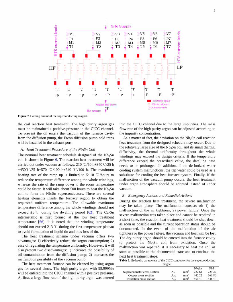
Figure 7. Cooling circuit of the superconducting magnet.
6
Helium cross section in bundle region AHeB mm2 286.21 344.43
Helium cross section in central hole AHeH mm2 78.54 113.10
SS jacket cross section ASS mm2 1855.77 1778.16
Void fraction Vf - 0.30 0.343
n-index - 10 10
Residual resistivity ratio RRR - 100 100
Surface perforation from central
channel to bundle
PERF0R -- 0.1 0.15
Conductor Helium wetted perimeter PHTC mm 2748.26 2752.03
Jacket Helium wetted perimeter PHTJ mm 58.59 59.22
Jacket-Conductor wetted perimeter PHTCJ mm 58.59 59.22
Hole and bundle wetted perimeter PHTHB mm 31.42 37.70
Hydraulic diameter in bundle region DHB mm 0.3995 0.480
Hydraulic diameter in hole region DHH mm 10.0 12.0
Table 6. Strand characterization parameters of the Nb3Sn superconductors [6,
35, 63]. Parameter
Ca1 44.16
Ca2 6.742
Eps_0a 0.2804%
Bc2m(0) 31.75 T
Tcm 16.23 K
C 46636 A*T
P 0.9419
Q 2.539
Table 7. Strand characterization parameters of the NbTi superconductors [64,
65]. Parameter
C0 1.68512e11 A*T
Bc20 14.61 T
Tc0 9.03 K
α 1.00
β 1.54
γ 2.10
VI. THERMAL-HYDRAULIC ANALYSIS OF THE
SUPERCONDUCTING MAGNET
The Nb3Sn coils are layer-wound windings with eight layers;
each layer has one cooling channel. The NbTi coils are
pancake-winding with 20 pancakes. There are 10 cooling
channels for NbTi coils; each cooling channel consists of two
pancakes. Figure 7 shows the cooling circuit of the
superconducting magnet. The Nb3Sn CICC conductors are
cooled with the forced flow supercritical helium at 0.55 MPa
pressure, 12 g/s mass flow rate and 4.5 K temperature at the
coil inlet. The NbTi coils are cooled with supercritical helium
at inlet pressure of 0.55 MPa, mass flow rate of 8 g/s and 4.5
K temperature at the inlet. The hydraulic parameters of the
Nb3Sn and NbTi CICCs for the superconducting magnet are
shown in table 5 [6, 47].
A. Critical Current Scaling Law for the Nb3Sn and NbTi
Strands
The scaling law for the strain dependence of the critical
current density in Nb3Sn superconductor can be obtained from
the relevant expressions [63]. The scaling parameters of the
Nb3Sn superconductor is shown in table 6 [6, 47, 63]. The
effective filament diameter of 30 μm for the Nb3Sn strand [6,
47]. The thermal strain of Nb3Sn strand inside the 316LN
stainless steel was assumed as -0.664% [47]. The strain
generated by the electromagnetic force was shown in figure 3.
The critical current density of the NbTi superconductor can be
obtained by using the single pinning model [64]. The critical
current density of the NbTi superconductor can be expressed
as [64, 65],
))(1())(
1())(
(),( 7.1
022
0
CCC T
T
TB
B
TB
B
B
CTBJ
C (1)
))(1()( 7.1
0
202
CCC T
TBTB (2)
The relevant scaling law parameters of the NbTi strands can
be shown in table 7. The effective filament diameter is about 8
μm for the NbTi strand. An accurate evaluation of the
coupling time constant of the CICC conductors is a hard work.
The coupling time constants of the CICC conductors depend
on the local magnetic forces, the load cycle history, void
fraction, cable pattern, aspect ratio, coating material of the
cable, and the magnet ramp rate, etc. [66-71]. For simplicity,
the coupling time constants of the Nb3Sn CICC conductor and
the NbTi CICC conductor were selected as 0.075 s and 0.15 s
for evaluating AC losses respectively.
0 15 30 45 60 75 90 105 120 135 1508
9
10
11
12
13
Magnetic field
Current sharing temperature
Along the cooling length (m)
B (
T)
6.0
6.5
7.0
7.5
8.0
8.5
9.0
Tcs (K
)
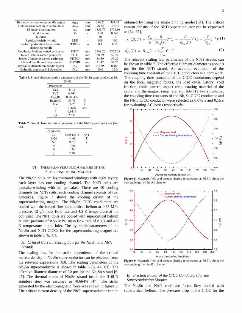
Figure 8. Magnetic field and current sharing temperature at 56 kA along the
cooling length of the A1 channel.
0 20 40 60 80 100 120 140 160 180 2003.0
3.5
4.0
4.5
5.0
5.5
6.0 Magnetic field
Current sharing temperature
Along the cooling length (m)
B (
T)
6.2
6.4
6.6
6.8
7.0
7.2
7.4
Tcs (K
)
Figure 9. Magnetic field and current sharing temperature at 56 kA along the
cooling length of the B1 channel.
B. Friction Factor of the CICC Conductors for the
Superconducting Magnet
The Nb3Sn and NbTi coils are forced-flow cooled with
supercritical helium. The pressure drop in the CICC for the
7
central channel and the bundle of the superconducting magnet
can be expressed as (3)-(5) [65, 72, 75],
vvD
f
dx
dp
h
2 (3)
)0231.0Re
5.19(
4
17953.0742.0
f
bundlef
(4)
25.0Re
136.0
04.0centralf (5)
where dp/dx is the pressure gradient, f is the friction factor,
fbundle and fcentral are friction factors of the bundle and the
central channel, ρ is the density of the helium, v is the flow
speed, vf is the void fraction, Re is the Reynolds number, Dh is
the hydraulic diameter.
C. Current sharing temperature of the superconducting
magnet
The thermal-hydraulic behavior of the innermost layer of the
Nb3Sn coil was analyzed due to its lower minimum
temperature margin compared with that of the other layers for
the Nb3Sn coils. For the NbTi coils, the lowest value of the
minimum temperature margin is located at the top and bottom
channels. So, we only analyze the thermal-hydraulic behavior
of the top channel of the NbTi coil. The innermost layer of the
Nb3Sn coil and the top channel of the NbTi coil can be
referred as A1 and B1 channels. Figures 8 and 9 show the
current sharing temperature of the A1 channel and the B1
channel when the superconducting magnet is ramped up to the
full field. It is shown that the minimum current sharing
temperature are about 6.3 K for the A1 channel and 6.4 K for
the B1 channel.
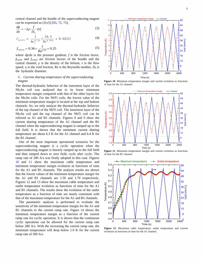
One of the most important operational scenarios for the
superconducting magnet is a cyclic operation when the
superconducting magnet is linearly ramped up to the full field
and then ramped down to zero field, cycle after cycle. The
ramp rate of 280 A/s was firstly adopted in this case. Figures
10 and 11 show the maximum cable temperature and
minimum temperature margin evolution as functions of time
for the A1 and B1 channels. The analysis results are shown
that the lowest values of the minimum temperature margin for
the A1 and B1 channels are 1.50 and 1.70 respectively.
Figures 12 and 13 show the maximum cable temperature and
outlet temperature evolution as functions of time for the A1
and B1 channels. The results show the evolution of the outlet
temperature as a function of time are nearly consistent with
that of the maximum temperature for the A1 and B1 channels.
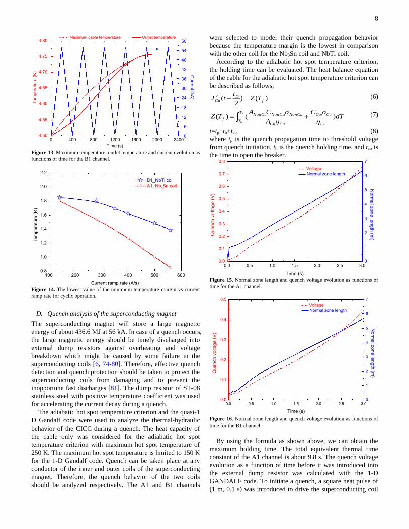
The parametric analysis is performed to evaluate the
sensitivity of the minimum temperature margin for the A1 and
B1 channels to the current ramp rate. Figure 14 shows the
minimum temperature margin as a function of the current
ramp rate for cyclic operation. It is shown that the continuous
cyclic operations can be allowed for the current ramp rate
below 280 A/s. With the increasing the current ramp rate, the
minimum temperature will drop below 1.0 K for the current
ramp rate of 500 A/s.
0 400 800 1200 1600 2000 24001
2
3
4
5
6
7
8
9
10
11 Minimum temperature margin Current
Time (s)
Te
mp
era
ture
(K
)
0
6
12
18
24
30
36
42
48
54
60C
urre
nt (k
A)
Figure 10. Minimum temperature margin and current evolution as functions
of time for the A1 channel.
0 400 800 1200 1600 2000 24001.0
1.5
2.0
2.5
3.0
3.5
4.0
4.5
5.0
Minimum temperature margin Current
Time (s)
Te
mp
era
ture
(K
)
0
6
12
18
24
30
36
42
48
54
60
Cu
rren
t (kA
)
Figure 11. Minimum temperature margin and current evolution as functions
of time for the B1 channel.
0 400 800 1200 1600 2000 24004.4
4.5
4.6
4.7
4.8
4.9
5.0
5.1
5.2
5.3
5.4
0 400 800 1200 1600 2000 2400
0
6
12
18
24
30
36
42
48
54
60
Te
mp
era
ture
(K
)
Time (s)
Maximum temperature Outlet temperature
Cu
rren
t (kA
)
Figure 12. Maximum cable temperature, outlet temperature and current
evolution as functions of time for the A1 channel.
8
0 400 800 1200 1600 2000 24000
6
12
18
24
30
36
42
48
54
60 Maximum cable temperature Outlet temperature
Time (s)
Cu
rren
t (kA
)
4.50
4.55
4.60
4.65
4.70
4.75
4.80
Te
mp
era
ture
(K
)
Figure 13. Maximum temperature, outlet temperature and current evolution as
functions of time for the B1 channel.
100 200 300 400 500 6000.8
1.0
1.2
1.4
1.6
1.8
2.0
2.2
Te
mp
era
ture
(K
)
Current ramp rate (A/s)
B1_NbTi coil
A1_Nb3Sn coil
Figure 14. The lowest value of the minimum temperature margin vs current
ramp rate for cyclic operation.
D. Quench analysis of the superconducting magnet
The superconducting magnet will store a large magnetic
energy of about 436.6 MJ at 56 kA. In case of a quench occurs,
the large magnetic energy should be timely discharged into
external dump resistors against overheating and voltage
breakdown which might be caused by some failure in the
superconducting coils [6, 74-80]. Therefore, effective quench
detection and quench protection should be taken to protect the
superconducting coils from damaging and to prevent the
inopportune fast discharges [81]. The dump resistor of ST-08
stainless steel with positive temperature coefficient was used
for accelerating the current decay during a quench.
The adiabatic hot spot temperature criterion and the quasi-1
D Gandalf code were used to analyze the thermal-hydraulic
behavior of the CICC during a quench. The heat capacity of
the cable only was considered for the adiabatic hot spot
temperature criterion with maximum hot spot temperature of
250 K. The maximum hot spot temperature is limited to 150 K
for the 1-D Gandalf code. Quench can be taken place at any
conductor of the inner and outer coils of the superconducting
magnet. Therefore, the quench behavior of the two coils
should be analyzed respectively. The A1 and B1 channels
were selected to model their quench propagation behavior
because the temperature margin is the lowest in comparison
with the other coil for the Nb3Sn coil and NbTi coil.
According to the adiabatic hot spot temperature criterion,
the holding time can be evaluated. The heat balance equation
of the cable for the adiabatic hot spot temperature criterion can
be described as follows,
)()2
(2
fD
Cu TZt
tJ (6)
dTC
A
CATZ
Cu
CuCuT
TCuCu
NonCuNonCuNonCu
f
f
b
)()(
(7)
t=tp+th+tcb (8)
where tp is the quench propagation time to threshold voltage
from quench initiation, th is the quench holding time, and tcb is
the time to open the breaker.
0.0 0.5 1.0 1.5 2.0 2.5 3.00.0
0.1
0.2
0.3
0.4
0.5
0.6
0.7
0.8
Voltage
Normal zone length
Time (s)
Qu
en
ch
vo
lta
ge
(V
)
0
1
2
3
4
5
6
7
No
rma
l zo
ne
len
gth
(m)
Figure 15. Normal zone length and quench voltage evolution as functions of
time for the A1 channel.
0.0 0.5 1.0 1.5 2.0 2.5 3.00.0
0.1
0.2
0.3
0.4
0.5
Voltage
Normal zone length
Time (s)
Qu
en
ch
vo
lta
ge
(V
)
0
1
2
3
4
5
6
7
No
rma
l zo
ne
len
gth
(m)
Figure 16. Normal zone length and quench voltage evolution as functions of
time for the B1 channel.
By using the formula as shown above, we can obtain the
maximum holding time. The total equivalent thermal time
constant of the A1 channel is about 9.8 s. The quench voltage
evolution as a function of time before it was introduced into
the external dump resistor was calculated with the 1-D
GANDALF code. To initiate a quench, a square heat pulse of
(1 m, 0.1 s) was introduced to drive the superconducting coil
9
into the resistive state from the superconducting state. The
quench energy adopted is about 2 times the energy needed to
initiate a propagating quench. Figure 15 shows the normal
zone length and quench voltage as functions of time for the A1
channel. It takes about 1.80 s to reach the quench voltage of
0.4 V. The time for opening the circuit breaker is about 0.5 s.
The equivalent thermal discharge time constant of the A1
channel is selected as 2.8 s. The maximum holding time can
be obtained as 6.1 s by taking into account the threshold
voltage of 0.4 V if the quench originated from the A1 channel.
0 2 4 6 8 10 12 14 16 18 200
10
20
30
40
50
60
70
80
90
Maximum temperature
Current
Time (s)
Te
mp
era
ture
(K
)
0
10000
20000
30000
40000
50000
60000
Cu
rren
t (A)
Figure 17. Hot spot temperature evolution as a function of time for the A1
channel.
64 66 68 70 72 74 76 780
10
20
30
40
50
60
70
80
90
Te
mp
era
ture
(K
)
Along the cooling length (m)
2 s
3 s
4 s
5 s
6 s
7 s
9 s
Figure 18. Cable temperature evolution along the cooling length as a function
of time for the A1 channel.
The total equivalent thermal time constant of the B1
channel is about 8.2 s. Figure 16 shows the normal zone length
and quench voltage as functions of time for the B1 channel. It
takes about 2.78 s to reach the quench voltage of 0.4 V. The
maximum holding time can be obtained as 3.52 s by taking
into account the threshold voltage of 0.4 V and the equivalent
thermal discharge time constant of 2.8 s if the quench
originated from the B1 channel. The threshold voltage and
holding time can be designed as 0.4 V and 2.0 s respectively.
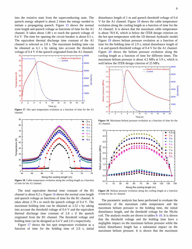
Figure 17 shows the hot spot temperature evolution as a
function of time for the holding time of 2.0 s, initial
disturbance length of 1 m and quench threshold voltage of 0.4
V for the A1 channel. Figure 18 shows the cable temperature
evolution along the cooling length as a function of time for the
A1 channel. It is shown that the maximum cable temperature
is about 78.9 K, which is below the ITER design criterion on
the hot spot temperature with the 1D thermal–hydraulic model.
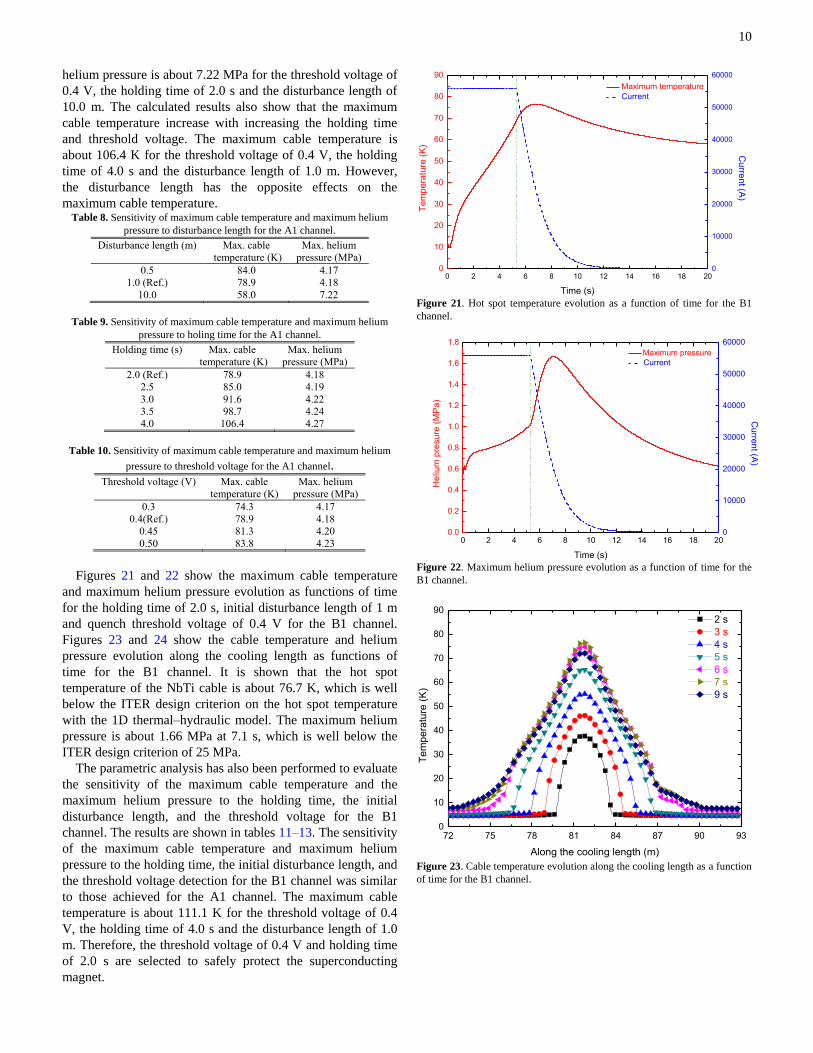
Figure 19 shows helium pressure evolution as a function of
time for the holding time of 2.0 s, initial disturbance length of
1 m and quench threshold voltage of 0.4 V for the A1 channel.
Figure 20 shows the helium pressure evolution along the
cooling length as a function of time for different times. The
maximum helium pressure is about 4.2 MPa at 5.9 s, which is
well below the ITER design criterion of 25 MPa.
0 2 4 6 8 10 12 14 16 18 200.0
0.5
1.0
1.5
2.0
2.5
3.0
3.5
4.0
4.5
Maximum helium pressure
Current
Time (s)
He
lium
pre
ssu
re (
MP
a)
0
10000
20000
30000
40000
50000
60000
Cu
rren
t (A)
Figure 19. Maximum helium pressure evolution as a function of time for the
A1 channel.
0 15 30 45 60 75 90 105 120 135 1500.0
0.5
1.0
1.5
2.0
2.5
3.0
3.5
4.0
4.5
He
lium
pre
ssu
re (
MP
a)
Along the cooling length (m)
0.5 s
2 s
3 s
4 s
5 s
6 s
7 s
8 s
9 s
Figure 20. Helium pressure evolution along the cooling length as a function
of time for the A1 channel.
The parametric analysis has been performed to evaluate the
sensitivity of the maximum cable temperature and the
maximum helium pressure to the holding time, the initial
disturbance length, and the threshold voltage for the Nb3Sn
coil. The analysis results are shown in tables 8–10. It is shown
that the threshold voltage and the holding time have a
negligible impact on the maximum helium pressure while the
initial disturbance length has a substantial impact on the
maximum helium pressure. It is shown that the maximum
10
helium pressure is about 7.22 MPa for the threshold voltage of
0.4 V, the holding time of 2.0 s and the disturbance length of
10.0 m. The calculated results also show that the maximum
cable temperature increase with increasing the holding time
and threshold voltage. The maximum cable temperature is
about 106.4 K for the threshold voltage of 0.4 V, the holding
time of 4.0 s and the disturbance length of 1.0 m. However,
the disturbance length has the opposite effects on the
maximum cable temperature. Table 8. Sensitivity of maximum cable temperature and maximum helium
pressure to disturbance length for the A1 channel. Disturbance length (m) Max. cable
temperature (K)
Max. helium
pressure (MPa)
0.5 84.0 4.17
1.0 (Ref.) 78.9 4.18
10.0 58.0 7.22
Table 9. Sensitivity of maximum cable temperature and maximum helium
pressure to holing time for the A1 channel. Holding time (s) Max. cable
temperature (K)
Max. helium
pressure (MPa)
2.0 (Ref.) 78.9 4.18
2.5 85.0 4.19
3.0 91.6 4.22
3.5 98.7 4.24
4.0 106.4 4.27
Table 10. Sensitivity of maximum cable temperature and maximum helium
pressure to threshold voltage for the A1 channel.
Threshold voltage (V) Max. cable
temperature (K)
Max. helium
pressure (MPa)
0.3 74.3 4.17
0.4(Ref.) 78.9 4.18
0.45 81.3 4.20
0.50 83.8 4.23
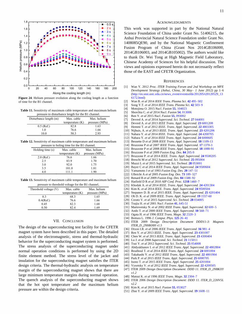
Figures 21 and 22 show the maximum cable temperature
and maximum helium pressure evolution as functions of time
for the holding time of 2.0 s, initial disturbance length of 1 m
and quench threshold voltage of 0.4 V for the B1 channel.
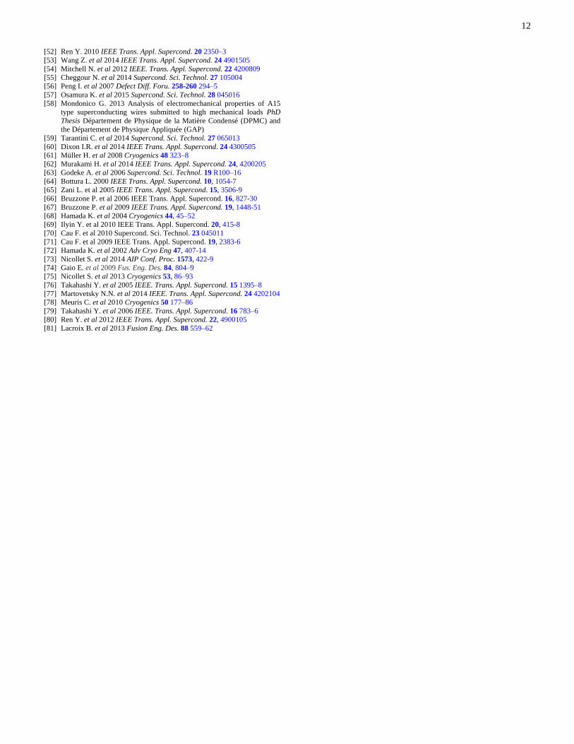
Figures 23 and 24 show the cable temperature and helium
pressure evolution along the cooling length as functions of
time for the B1 channel. It is shown that the hot spot
temperature of the NbTi cable is about 76.7 K, which is well
below the ITER design criterion on the hot spot temperature
with the 1D thermal–hydraulic model. The maximum helium
pressure is about 1.66 MPa at 7.1 s, which is well below the
ITER design criterion of 25 MPa.
The parametric analysis has also been performed to evaluate
the sensitivity of the maximum cable temperature and the
maximum helium pressure to the holding time, the initial
disturbance length, and the threshold voltage for the B1
channel. The results are shown in tables 11–13. The sensitivity
of the maximum cable temperature and maximum helium
pressure to the holding time, the initial disturbance length, and
the threshold voltage detection for the B1 channel was similar
to those achieved for the A1 channel. The maximum cable
temperature is about 111.1 K for the threshold voltage of 0.4
V, the holding time of 4.0 s and the disturbance length of 1.0
m. Therefore, the threshold voltage of 0.4 V and holding time
of 2.0 s are selected to safely protect the superconducting
magnet.
0 2 4 6 8 10 12 14 16 18 200
10
20
30
40
50
60
70
80
90
Maximum temperature
Current
Time (s)
Te
mp
era
ture
(K
)
0
10000
20000
30000
40000
50000
60000C
urre
nt (A
)
Figure 21. Hot spot temperature evolution as a function of time for the B1
channel.
0 2 4 6 8 10 12 14 16 18 200.0
0.2
0.4
0.6
0.8
1.0
1.2
1.4
1.6
1.8
Maximum pressure
Current
Time (s)
He
lium
pre
su
re (
MP
a)
0
10000
20000
30000
40000
50000
60000
Cu
rren
t (A)
Figure 22. Maximum helium pressure evolution as a function of time for the
B1 channel.
72 75 78 81 84 87 90 930
10
20
30
40
50
60
70
80
90
Te
mp
era
ture
(K
)
Along the cooling length (m)
2 s
3 s
4 s
5 s
6 s
7 s
9 s
Figure 23. Cable temperature evolution along the cooling length as a function
of time for the B1 channel.
11
0 20 40 60 80 100 120 140 160 180 2000.0
0.2
0.4
0.6
0.8
1.0
1.2
1.4
1.6
1.8
H
eliu
m p
ressu
re (
MP
a)
Along the cooling length (m)
0.5 s
2 s
3 s
4 s
5 s
6 s
7 s
8 s
9 s
Figure 24. Helium pressure evolution along the cooling length as a function
of time for the B1 channel.
Table 11. Sensitivity of maximum cable temperature and maximum helium
pressure to disturbance length for the B1 channel. Disturbance length (m) Max. cable
temperature (K)
Max. helium
pressure (MPa)
0.5 (Ref.) 82.8 1.63
1.0 76.6 1.66
10.0 50.3 2.93
Table 12. Sensitivity of maximum cable temperature and maximum helium
pressure to holing time for the B1 channel. Holding time (s) Max. cable
temperature (K)
Max. helium
pressure (MPa)
2.0 (Ref.) 76.6 1.66
2.5 83.9 1.70
3.0 92.0 1.75
3.5 101.0 1.81
4.0 111.1 1.90
Table 13. Sensitivity of maximum cable temperature and maximum helium
pressure to threshold voltage for the B1 channel.
Threshold voltage (V) Max. cable
temperature (K)
Max. helium
pressure (MPa)
0.3 68.3 1.65
0.4(Ref.) 76.6 1.66
0.45 82.3 1.68
0.50 82.4 1.69
VII. CONCLUSION
The design of the superconducting test facility for the CFETR
magnet system have been described in this paper. The detailed
analysis of the electromagnetic, stress and thermal-hydraulic
behavior for the superconducting magnet system is performed.
The stress analysis of the superconducting magnet under
normal operation conditions is performed by using the 2D
finite element method. The stress level of the jacket and
insulation for the superconducting magnet satisfies the ITER
design criteria. The thermal-hydraulic analysis on temperature
margin of the superconducting magnet shows that there are
large minimum temperature margins during normal operation.
The quench analysis of the superconducting magnet shows
that the hot spot temperature and the maximum helium
pressure are within the design criteria.
ACKNOWLEDGMENTS
This work was supported in part by the National Natural
Science Foundation of China under Grant No. 51406215, the
Anhui Provincial Natural Science Foundation under Grant No.
1408085QE90, and by the National Magnetic Confinement
Fusion Program of China (Grant Nos 2014GB106000,
2014GB106003, and 2014GB105002). The authors would like
to thank Dr. Wei Tong at High Magnetic Field Laboratory,
Chinese Academy of Sciences for his helpful discussion. The
views and opinions expressed herein do not necessarily reflect
those of the EAST and CFETR Organization.
REFERENCES
[1] Wan Y. 2012 Proc. ITER Training Forum and 2nd Workshop on MFE
Development Strategy (Anhui, China, 30 May– 1 June 2012) pp 1–6
(http://en.snst.ustc.edu.cn/news_event/eventssfds/201205/t20120529_13
6172.html)
[2] Wan B. et al 2014 IEEE Trans. Plasma Sci. 42 495–502
[3] Song Y.T. et al 2014 IEEE Trans. Plasma Sci. 42 503–9
[4] Motojima O. 2015 Nucl. Fusion 55, 104023
[5] Sborchia C. et al 2014 Nucl. Fusion 54, 013006
[6] Ren Y. et al 2015 Nucl. Fusion 55, 093002
[7] Devred A. et al 2014 Supercond. Sci. Technol. 27 044001
[8] Devred A. et al 2013 IEEE Trans. Appl. Supercond. 23 6001208
[9] Hemmi T. et al 2012 IEEE. Trans. Appl. Supercond. 22 4803305
[10] Nijhuis, A. et al 2013 IEEE. Trans. Appl. Supercond. 23 4201206
[11] Nabara Y. et al 2014 IEEE. Trans. Appl. Supercond. 24 4200705
[12] Nabara Y. et al 2014 IEEE Trans. Appl. Supercond. 24 6000605
[13] Bessette D et al 2008 IEEE Trans. Appl. Supercond. 18 1109-13
[14] Bruzzone P et al 2007 IEEE Trans. Appl. Supercond. 17 1370-3
[15] Bruzzone P et al 2008 IEEE Trans. Appl. Supercond. 18 1088-91
[16] Bruzzone P et al 2009 Fusion Eng. Des. 84 205-9
[17] Bruzzone P. et al 2014 IEEE. Trans. Appl. Supercond. 24 9500205
[18] Breschi M et al 2012 Supercond. Sci. Technol. 25 095004
[19] Muzzi L et al 2015 Supercond. Sci. Technol. 28 053001
[20] Bayer C et al 2014 IEEE Trans. Appl. Supercond. 24 9500604
[21] Yamamoto J et al 1993 Fusion Eng. Des. 20 147–51
[22] Ulbricht A et al 2005 Fusion Eng. Des. 73 189–327
[23] Renard B et al 2009 Fusion Eng. Des. 84 1588–92
[24] Hatfield D R et al 2010 AIP Conf. Proc. 1218 1460–7
[25] Khodak A. et al 2014 IEEE. Trans. Appl. Supercond. 24 4201304
[26] Kim K. et al 2014 IEEE. Trans. Appl. Supercond. 24 9500504
[27] Stepanov D. B. et al 2015 IEEE. Trans. Appl. Supercond. 25 4201404
[28] Oh D. K. et al 2009 IEEE. Trans. Appl. Supercond. 19 1557-60
[29] Corato V. et al 2015 Supercond. Sci. Technol. 28 034005
[30] Tsujia H. et al 2001 Nucl. Fusion 41, 645-51
[31] Martovetsky N. et al 2002 IEEE Trans. Appl. Supercond. 12 600–5
[32] Ando T. et al 2000 IEEE Trans. Appl. Supercond. 10 568–71
[33] Ogata H. et al 1996 IEEE Trans. Magn. 32 2320–3
[34] Bottura L. 1996 J. Comput. Phys. 125 26–41
[35] ITER 2009 Design Description Document DDD11-3: Magnets
ITER_D_2NHKHH v1.5
[36] Dixon I.R. et al 2006 IEEE Trans. Appl. Supercond. 16 981–4
[37] Ren Y. et al 2013 IEEE. Trans. Appl. Supercond. 23 4301007
[38] Chen W. et al 2013 IEEE. Trans. Appl. Supercond. 23 4300404
[39] Lu J. et al 2008 Supercond. Sci. Technol. 21 115011
[40] Tsui Y. et al 2012 Supercond. Sci. Technol. 25 054008
[41] Abdyukhanov I. et al 2012 IEEE Trans. Appl. Supercond. 22 4802804
[42] Boutboul T. et al 2014 IEEE Trans. Appl. Supercond. 24 6001004
[43] Takahashi Y. et al 2012 IEEE Trans. Appl. Supercond. 22 4801904
[44] Park P. et al 2015 IEEE Trans. Appl. Supercond. 25 6000705
[45] Isono T. et al 2015 IEEE Trans. Appl. Supercond. 25 4201004
[46] Vysotsky V. et al 2012 IEEE Trans. Appl. Supercond. 22 4200505
[47] ITER 2009 Design Description Document: DDD 11. ITER_D_2NBKXY
v1.2
[48] Matsui K. et al 1996 IEEE Trans. Magn. 32 2304–7
[49] ITER 2006 Design Description Document: DDD 11. ITER_D_22HV5L
v2.2
[50] Kim K. et al 2015 Nucl. Fusion 55, 053027
[51] Zhai Y. et al 2009 IEEE Trans. Appl. Supercond. 19 1608–11
12
[52] Ren Y. 2010 IEEE Trans. Appl. Supercond. 20 2350–3
[53] Wang Z. et al 2014 IEEE Trans. Appl. Supercond. 24 4901505
[54] Mitchell N. et al 2012 IEEE. Trans. Appl. Supercond. 22 4200809
[55] Cheggour N. et al 2014 Supercond. Sci. Technol. 27 105004
[56] Peng I. et al 2007 Defect Diff. Foru. 258-260 294–5
[57] Osamura K. et al 2015 Supercond. Sci. Technol. 28 045016
[58] Mondonico G. 2013 Analysis of electromechanical properties of A15
type superconducting wires submitted to high mechanical loads PhD
Thesis Département de Physique de la Matière Condensé (DPMC) and
the Département de Physique Appliquée (GAP)
[59] Tarantini C. et al 2014 Supercond. Sci. Technol. 27 065013
[60] Dixon I.R. et al 2014 IEEE Trans. Appl. Supercond. 24 4300505
[61] Müller H. et al 2008 Cryogenics 48 323–8
[62] Murakami H. et al 2014 IEEE Trans. Appl. Supercond. 24, 4200205
[63] Godeke A. et al 2006 Supercond. Sci. Technol. 19 R100–16
[64] Bottura L. 2000 IEEE Trans. Appl. Supercond. 10, 1054-7
[65] Zani L. et al 2005 IEEE Trans. Appl. Supercond. 15, 3506-9
[66] Bruzzone P. et al 2006 IEEE Trans. Appl. Supercond. 16, 827-30
[67] Bruzzone P. et al 2009 IEEE Trans. Appl. Supercond. 19, 1448-51
[68] Hamada K. et al 2004 Cryogenics 44, 45–52
[69] Ilyin Y. et al 2010 IEEE Trans. Appl. Supercond. 20, 415-8
[70] Cau F. et al 2010 Supercond. Sci. Technol. 23 045011
[71] Cau F. et al 2009 IEEE Trans. Appl. Supercond. 19, 2383-6
[72] Hamada K. et al 2002 Adv Cryo Eng 47, 407-14
[73] Nicollet S. et al 2014 AIP Conf. Proc. 1573, 422-9
[74] Gaio E. et al 2009 Fus. Eng. Des. 84, 804–9
[75] Nicollet S. et al 2013 Cryogenics 53, 86–93
[76] Takahashi Y. et al 2005 IEEE. Trans. Appl. Supercond. 15 1395–8
[77] Martovetsky N.N. et al 2014 IEEE. Trans. Appl. Supercond. 24 4202104
[78] Meuris C. et al 2010 Cryogenics 50 177–86
[79] Takahashi Y. et al 2006 IEEE. Trans. Appl. Supercond. 16 783–6
[80] Ren Y. et al 2012 IEEE Trans. Appl. Supercond. 22, 4900105
[81] Lacroix B. et al 2013 Fusion Eng. Des. 88 559–62