electric service manual - talgov.com
TRANSCRIPT
Electric Service Manual
Revision 0 Issued: 12/9/20
City Commission Approval: 12/9/20
In the event there is a discrepancy between the City of Tallahassee Code of Ordinances and this document then the Code of Ordinances has precedence.

Record of Revisions and Review
Rev. No.
Date
Description
By
Approval
0 12/9/2020 New Document ELECTRIC Rob McGarrah

Electric Service Manual Table of Contents
1. Introduction 1.1 – Electric & Gas Utility Quick Reference Guide 1 1.2 – Electric & Gas Mission 3 1.3 – Electric & Gas Utility Objectives 3 2. General Information 2.1 - Definitions 3 2.2 - Availability and Location of Service 7 2.3 - Permits and Inspections 9 2.4 - Access to City Equipment and Facilities 10 2.5 – Electric & Gas Easements and Rights-of-Way 11 2.6 - Character of Service 12 2.7 - Alterations and Additions 13 2.8 - General Safety 14 2.9 - Refusal or Discontinuance of Electric Service 14 2.10 - Joint Use of Electric Facilities 14 3. Service Policy 3.1 - Point of Service 15 3.2 - Temporary Services 15 3.3 - Permanent Services 16 3.3.1 - Permanent Residential Service 16 3.3.2 - General Service (Commercial/Industrial) 19 3.3.3 - Downtown Underground Network 21 3.3.4 - Conversion from Overhead to Underground 22 3.3.5 - Special Services 22 4. Metering Installations and Locations 4.1 - General Requirements 23 4.2 - Conductor Marking 24 4.3 - Customer Purchased Equipment 24 4.4 - Meter Locations 24 4.5 - Instrument Transformer Installations 25 5. Street Light and Area Light Policies 5.1 - Street Lights 27 5.2 - Area Lights 27 6. Primary Voltage and Special Service Conditions 6.1 - Motors 27 7. Non-Net Metered Generator Interconnection 28 7.1 - Non-Renewable Generators 28 7.1.1 - Permitting 28 7.1.2 - Physical Isolation 29
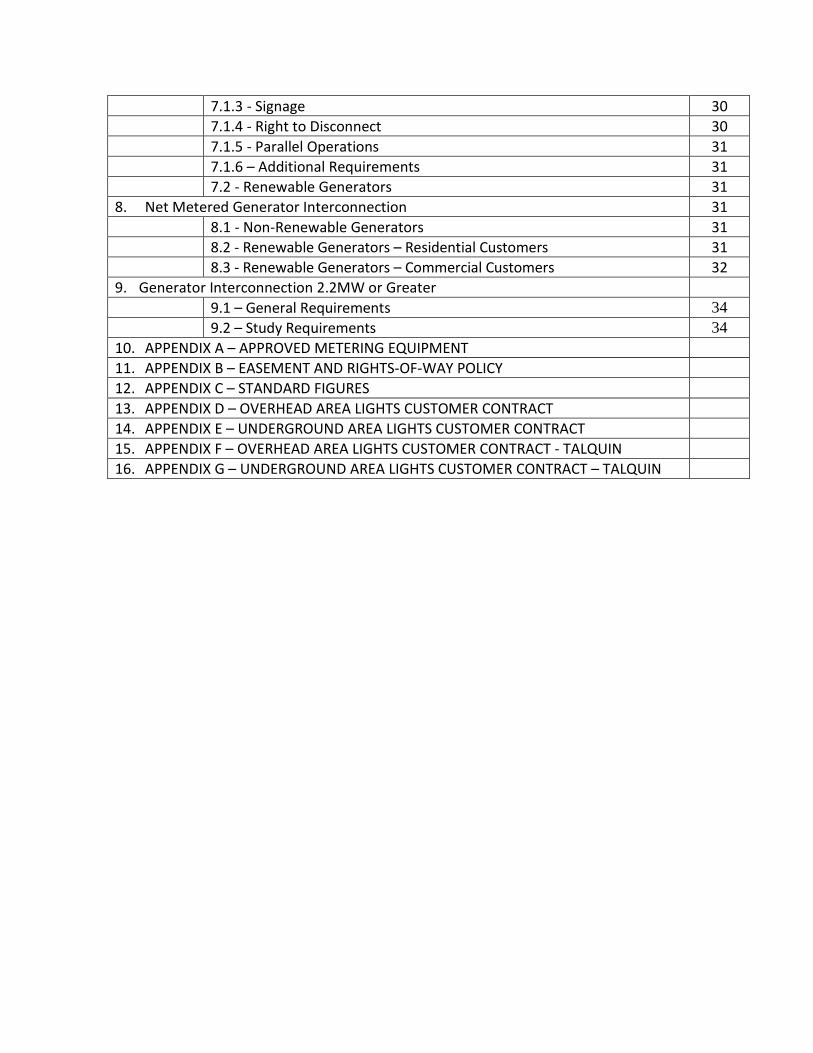
7.1.3 - Signage 30 7.1.4 - Right to Disconnect 30 7.1.5 - Parallel Operations 31 7.1.6 – Additional Requirements 31 7.2 - Renewable Generators 31 8. Net Metered Generator Interconnection 31 8.1 - Non-Renewable Generators 31 8.2 - Renewable Generators – Residential Customers 31 8.3 - Renewable Generators – Commercial Customers 32 9. Generator Interconnection 2.2MW or Greater 9.1 – General Requirements 34 9.2 – Study Requirements 34 10. APPENDIX A – APPROVED METERING EQUIPMENT 11. APPENDIX B – EASEMENT AND RIGHTS-OF-WAY POLICY 12. APPENDIX C – STANDARD FIGURES 13. APPENDIX D – OVERHEAD AREA LIGHTS CUSTOMER CONTRACT 14. APPENDIX E – UNDERGROUND AREA LIGHTS CUSTOMER CONTRACT 15. APPENDIX F – OVERHEAD AREA LIGHTS CUSTOMER CONTRACT - TALQUIN 16. APPENDIX G – UNDERGROUND AREA LIGHTS CUSTOMER CONTRACT – TALQUIN

Page 1
1. INTRODUCTION
1.1 Electric & Gas Utility Quick Reference Guide Utility Customer Service: (850) 891-4YOU (4968)
Call this number for general information, for Service requests, and for problems with your Service Report a Power Outage: (850) 891-4YOU (4968)
Call this number to report an outage, whether it is storm related or you forgot to pay your utility bill. Electric & Gas Utility Power Delivery Division: (850) 891-5031
Contact the Electric & Gas Utility Power Delivery Division for general assistance and information regarding the availability or type of Service for a specific location, alterations/additions to an existing Service, information on construction planning, and assistance with connecting to the downtown underground network.
Power Delivery Division 2602 Jackson Bluff Road Tallahassee, Florida, 32304 (850) 891-5031 Growth Management Permits and Inspections (within the city limits): (850) 891-7001
Electrical inspections and all required permits are obtained from the COT Growth Management Building Inspection Department located at 435 Macomb Street. Complete permitting and inspection information, including forms, are available on line at http://www.talgov.com/, click “Departments” and then “Growth Management”, or you can use the direct link here. Permits and Inspections (outside the city limits, in Leon County): (850) 606-1339
Outside the city limits, the Leon County Building Inspection Authority has jurisdiction. Information on permitting and inspections is available online at http://cms.leoncountyfl.gov, click on “Departments” and then on “Building Plans Review and Inspections”, or you can use the direct link here. Code of Ordinances and Land Development Code:
The City’s Codes, Ordinances, and Policies are available online at https://www.municode.com, click “Code Library” then “Florida” and then “Tallahassee” or you can use the direct link here.
Page 2
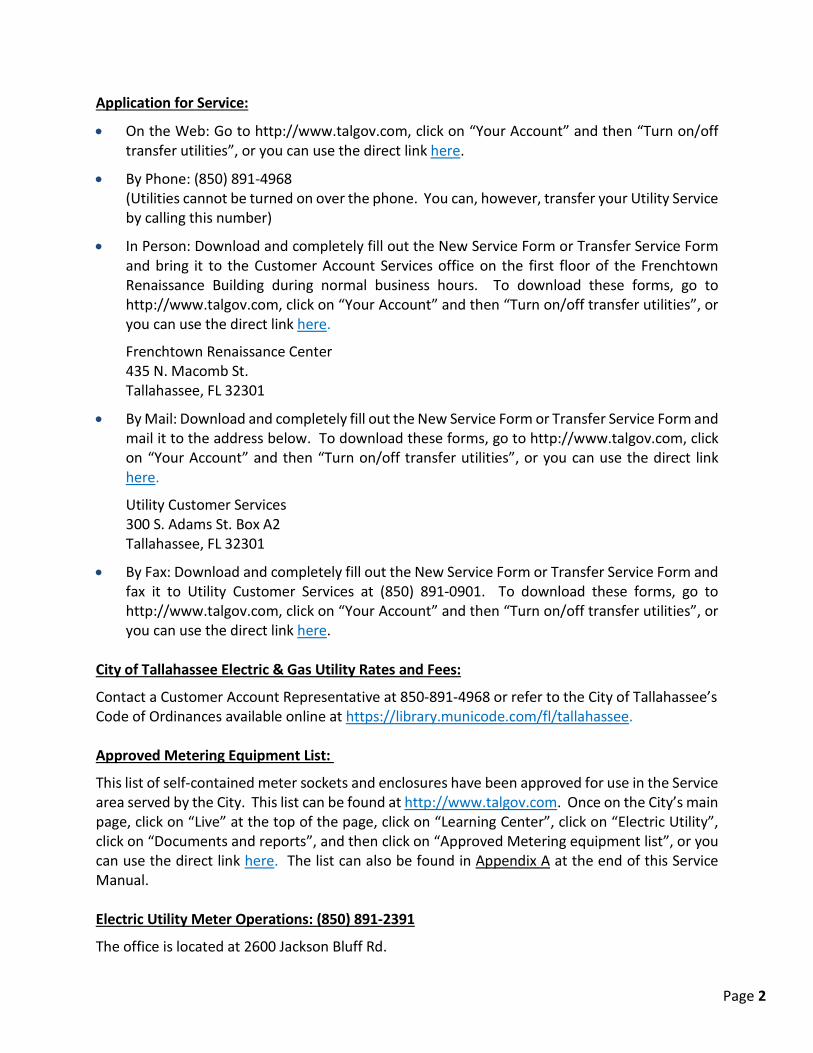
Application for Service:
• On the Web: Go to http://www.talgov.com, click on “Your Account” and then “Turn on/off transfer utilities”, or you can use the direct link here.
• By Phone: (850) 891-4968 (Utilities cannot be turned on over the phone. You can, however, transfer your Utility Service by calling this number)
• In Person: Download and completely fill out the New Service Form or Transfer Service Form and bring it to the Customer Account Services office on the first floor of the Frenchtown Renaissance Building during normal business hours. To download these forms, go to http://www.talgov.com, click on “Your Account” and then “Turn on/off transfer utilities”, or you can use the direct link here.
Frenchtown Renaissance Center 435 N. Macomb St. Tallahassee, FL 32301
• By Mail: Download and completely fill out the New Service Form or Transfer Service Form and mail it to the address below. To download these forms, go to http://www.talgov.com, click on “Your Account” and then “Turn on/off transfer utilities”, or you can use the direct link here.
Utility Customer Services 300 S. Adams St. Box A2 Tallahassee, FL 32301
• By Fax: Download and completely fill out the New Service Form or Transfer Service Form and fax it to Utility Customer Services at (850) 891-0901. To download these forms, go to http://www.talgov.com, click on “Your Account” and then “Turn on/off transfer utilities”, or you can use the direct link here.
City of Tallahassee Electric & Gas Utility Rates and Fees:
Contact a Customer Account Representative at 850-891-4968 or refer to the City of Tallahassee’s Code of Ordinances available online at https://library.municode.com/fl/tallahassee. Approved Metering Equipment List:
This list of self-contained meter sockets and enclosures have been approved for use in the Service area served by the City. This list can be found at http://www.talgov.com. Once on the City’s main page, click on “Live” at the top of the page, click on “Learning Center”, click on “Electric Utility”, click on “Documents and reports”, and then click on “Approved Metering equipment list”, or you can use the direct link here. The list can also be found in Appendix A at the end of this Service Manual. Electric Utility Meter Operations: (850) 891-2391
The office is located at 2600 Jackson Bluff Rd.
Page 3
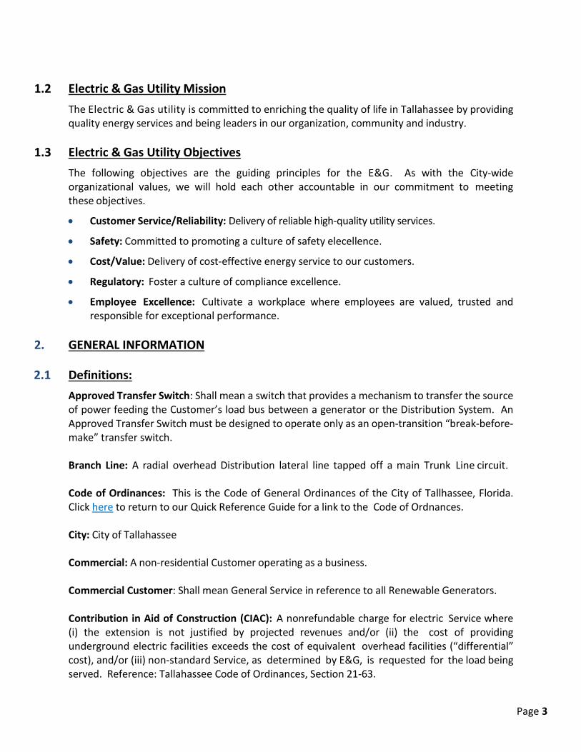
1.2 Electric & Gas Utility Mission
The Electric & Gas utility is committed to enriching the quality of life in Tallahassee by providing quality energy services and being leaders in our organization, community and industry.
1.3 Electric & Gas Utility Objectives The following objectives are the guiding principles for the E&G. As with the City-wide organizational values, we will hold each other accountable in our commitment to meeting these objectives.
• Customer Service/Reliability: Delivery of reliable high-quality utility services.
• Safety: Committed to promoting a culture of safety elecellence.
• Cost/Value: Delivery of cost-effective energy service to our customers.
• Regulatory: Foster a culture of compliance excellence.
• Employee Excellence: Cultivate a workplace where employees are valued, trusted and responsible for exceptional performance.
2. GENERAL INFORMATION
2.1 Definitions:
Approved Transfer Switch: Shall mean a switch that provides a mechanism to transfer the source of power feeding the Customer’s load bus between a generator or the Distribution System. An Approved Transfer Switch must be designed to operate only as an open-transition “break-before-make” transfer switch. Branch Line: A radial overhead Distribution lateral line tapped off a main Trunk Line circuit. Code of Ordinances: This is the Code of General Ordinances of the City of Tallhassee, Florida. Click here to return to our Quick Reference Guide for a link to the Code of Ordnances. City: City of Tallahassee Commercial: A non-residential Customer operating as a business. Commercial Customer: Shall mean General Service in reference to all Renewable Generators. Contribution in Aid of Construction (CIAC): A nonrefundable charge for electric Service where (i) the extension is not justified by projected revenues and/or (ii) the cost of providing underground electric facilities exceeds the cost of equivalent overhead facilities (“differential” cost), and/or (iii) non-standard Service, as determined by E&G, is requested for the load being served. Reference: Tallahassee Code of Ordinances, Section 21-63.

Page 4
Customer: User of the City’s electric service or an authorized representative. Demand: The rate at which electric energy in KW, KVA, or KVAR is metered per time interval (i.e., instantaneous, 15 minutes, 30 minutes, or one hour). The C i t y ’ s Demand rate is based on the highest 30-minute increment during the billing period. Distribution or Distribution System: All materials and equipment used by E&G to provide electric power to its Customers. Distribution Lines: Electric facilities with voltages of 46KV or lower. Easements: Property owned by others and granted to the City for the right to access, construct, maintain and operate Transmission and Distribution Lines. E&G: City of Tallahassee Electric & Gas Utility General Manager: shall mean the individual appointed by the Tallahassee City Manager to oversee the operations of the City’s Electric & Gas Utility. Generator Codes and Standards: shall mean the version of applicable codes and the following standards for Non-Renewable Generators in effect at the time of installation of the Non-Renewable Generator Connection at the Service Location: • IEEE1547 – Standard for Interconnecting Distributed Resources with Electric Power Systems; • IEEE1547.1 – Standards Conformance Test Procedures for Equipment Interconnecting
Distributed Resources with Electric Power Systems; • UL1741 – Inverters, Converters, Controllers and Interconnection System Equipment for use
with Distributed Energy Resources; • The applicable sections of the NEC, NESC, the American National Standards Institute, and
the Underwriters Laboratory. In the event of a conflict between applicable building codes and any other standard set forth above, the applicable building codes will take precedence. Generator Interconnection Agreement: Shall mean a written agreement signed by the Customer and City that specifies the requirements of the generator interconnection. Grid-Isolating Interconnection System: Shall mean a U.L. 67 classified product Listed by a U.S. Nationally Recognized Testing Laboratory designed to mechanically interlock the main breaker and a sub-breaker such that it provides a mechanism to automatically isolate the Non-Renewable Generator from the Distribution System during those periods in which the Non Renewable Generator is in operation. This Grid-Isolating Interconnection System must be designed to operate only as an open-transition “break-before-make” manually operated device. Ground: A conducting connection between an electrical circuit or piece of equipment and the earth, or to a conducting body that serves in place of the earth.

Page 5
Inspector or Inspection Authority: A person or agency authorized by a governmental body to inspect and approve electrical installations. kW: kilowatt, a measure of electrical Demand. Load Break Device: Shall mean a disconnect or other utility interface device that is, rated to break load, manual, lockable, and listed for the purpose that it is to be used. Maximum Available Fault Current (at Point of Delivery): The maximum current that would flow due to a direct short from one conductor to Ground or between conductors. Meter Operations: The E&G electric meter section within E&G System Operations. National Electrical Safety Code (NESC): A code sponsored under the auspices of the American National Standards Institute for safeguarding persons and property from hazards arising from the use of electricity. This code covers installations associated with utility lighting, communications, metering, generation, transmission or distribution of electric energy under the control of electric utilities or other private entities. This code does not cover installation of electric conductors and equipment within or on public and private buildings and facilities. National Electrical Code (NEC): A code sponsored by the National Fire Protection Association for safeguarding persons and property from hazards arising from the use of electricity. This code covers installation of electric conductors and equipment within or on public and private buildings and facilities. This code does not cover installations associated with utility lighting, communications, metering, generation, transmission or distribution of electric energy under the control of electric utilities. Net Metered Generators: Shall mean generators are subject to a written net metering agreement signed by the Customer and the City. Only Net Metered Generators shall be allowed to operate in Parallel with the Distribution System. Non-Renewable Generator: Shall mean an electric generating system that derives its operating power from non-renewable resources, including all ancillary equipment, which is designed to provide back-up power to the Service Entrance in the event of a loss of power from the City’s System. A Non-Renewable Generator shall not exceed 90% of the Customer’s utility Distribution rating. Permittee: A Customer, developer or an authorized representative who is applying for a permit. Parallel or Parallel Operation: Shall mean the concurrent interconnection of both the Distribution System and a generator to the Customer’s load bus such that power may flow from either source to the Customer’s load bus or the Distribution System.
Page 6
Point of Delivery: The point designated by the COT where the City’s conductors are connected to the Customer-owned conductors. This point defines the boundary of the City’s maintenance responsibility. Points of delivery vary by Service type. Typical points of delivery include: weatherheads, Service junction boxes, hand-holes, pedestals, pad-mounted transformers, manholes, and vaults. Power Leg (High Leg): The conductor in a three-phase, 4 wire delta secondary connection that has a higher voltage-to-Ground potential than the other phase conductors. Renewable Generator: Shall mean an electric generating system that derives its operating power from renewable resources, including all ancillary equipment. Residential Service: Electric Service supplied exclusively for domestic purposes in individually metered dwelling units, where permanent residency is established. Residential Service does not apply to business houses, licensed boarding houses or rooming houses, or when advertised as such, fraternity and sorority houses, educational institutions or apartment houses, except when the latter is served by a separate meter for each apartment. Rights-of-Way or ROW: Property owned by the City on which Transmission or Distribution Lines have been consturcted. Self-Contained Service: Self-contained meter assembly that operates from 0 - 320 amps. Separate current transformers are not installed; and the meter may be used to disconnect the Service Entrance. Service: The supply of electricity to the Customer, including the readiness and availability of electrical energy at the Point of Delivery at the designated voltage and frequency whether or not utilized by the Customer. Service Drop: The overhead secondary Service conductors between the City’s facilities/equipment and the Point of Delivery. Service Entrance: Customer-owned and maintained wires, conduits and enclosures connecting the Customer’s Service equipment to the Service Drop, Service Lateral, transformer bushing or other source of supply. Service Lateral: The underground Service conductors up to the Point of Delivery Temporary Electric Service: Electrical facilities, used to aid construction, that typically remain in use no longer than one year. Transmission Line: Electric facilities with voltages of 46KV or higher. Trunk Line: Feeder main or three phase primary voltage overhead or underground circuit which serves as a source for primary laterals or loops.
Page 7
Utility: Means a utility owned and operated by the City of Tallahassee, providing electricity, water and wastewater services, solid waste services, natural gas, and stormwater services, or any combination of the foregoing, and billing customers on a monthly or periodic basis.
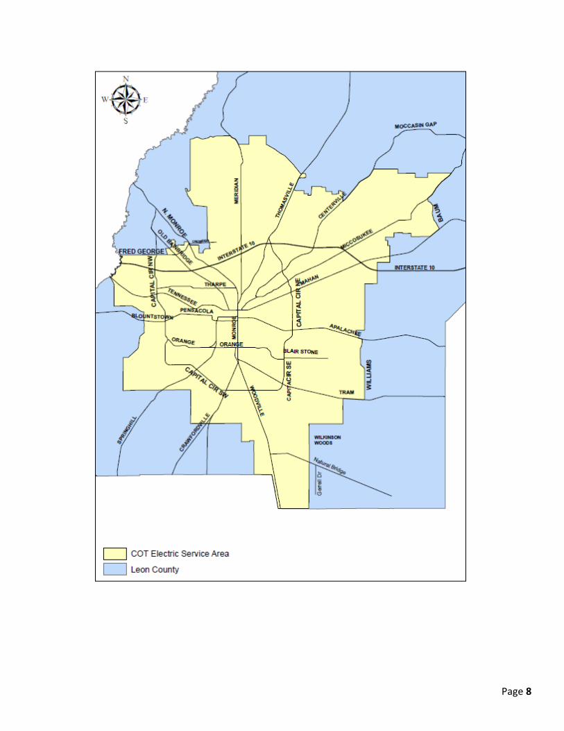
2.2 Availability and Location of Service: E&G provides Service to Customers in its Service area within Leon County, Florida, subject to the following conditions:
• An application for Service has been completed
• All applicable deposits and fees have been paid
• All required permits, Easements, and certificates of inspection have been obtained
• All requirements of any applicable ordinance have been met The E&G Power Delivery division will determine an original Point of Delivery and Service characteristics for all Services, typically at the property line or boundary for underground construction. If the Customer requests a different Point of Delivery than what was designated by a Utility representative, the Customer may incur additional cost for their electric Service. Information regarding the availability or type of Service for a specific location may be obtained by contacting the E&G Power Delivery division. Click here to return to our Quick Reference Guide for Power Delivery’s phone number.
Page 8

Page 9
2.3 Permits and Inspections: The permitting process and Inspection Authority having jurisdiction are dependent on whether the Customer’s Service location is within the City of Tallahassee or outside the City in Leon County. The Permittee must meet the requirements of the permitting agency (City or County) and Inspector as well as all applicable codes and standards. The drawings included in this manual reflect the requirements of the E&G Utility. Prior to a meter being set, an electrical inspection of the Customer’s meter base and wiring is required. This includes both temporary and permanent installations. Once the required electrical plans have been received, the E&G Power Delivery Division will determine the type and size of the electric Service to be provided and order the associated equipment. When all materials are received, construction will be scheduled. Before an electric Service order is issued to E&G, the Customer’s Service must have passed an electrical inspection, and the Customer must have submitted a request for Service application with the City’s Utility Customer Service. For City of Tallahassee
Within the city limits of Tallahassee, electrical inspections and all required permits are obtained from the City’s Growth Management Building Inspection Department. Click here to return to our Quick Reference Guide for more information and a direct link to this department’s website. The Permittee shall include the following as part of the permitting process:
A complete set of electrical plans for new, altered, or upgraded electrical Service designs shall be submitted to the City of Tallahassee Growth Management (Building Inspection) electrical inspection and the City of Tallahassee Electric & Gas Utility for approval before work is started, except on single-family detached and duplex dwellings. No electrical permit shall be issued until all corrections have been approved. Any work affecting the electrical Service location, size, or size increase must be approved prior to permitting by the E&G Utility. The minimum design and plan requirements for the E&G Utility are as follows: • A complete civil site plan showing all new buildings, all buildings being altered/upgraded, and
the parcel features (paved surfaces, stormwater retention facilities, protected green spaces, retaining walls, severe grade changes, etc.).
• A complete utility site plan and electrical plan(s) showing the location of Service Entrance equipment (including meter socket, CT/PT enclosure, and main disconnect) and the main electrical room identified (as applicable).
• Architectural elevational views of proposed/altered buildings or structures if overhead Service is being provided.
• The total area of the affected building(s) in square feet being supplied by the new, altered, or upgraded Service(s).
• A proposed location for a transformer or transformers either on the civil or utility site plan.

Page 10
• A desired location for Service and a preference for overhead or underground Service. • A Service single line riser diagram including the proposed:
i. Service voltage ii. Number, type, and size of Service conductors
iii. Service Entrance conduit size iv. Location of the C.T. enclosure (as required) v. Location of the meter enclosure (meter base)
vi. Location of the Service main disconnect/switchgear vii. Location of other disconnects and electrical Distribution panels (sub-panels)
viii. Grounding electrodes and electrode conductor • The total connected load before applying Demand factors, the Demand factors used, and the
computed load after applying Demand factors. • Complete panel schedules. E&G will review the plans to determine: • The Service voltage and whether the proposed Service qualifies for three-phase voltage. • The size of the Service transformer(s) (as needed). • The placement location of the Service transformer(s) (as needed). • The maximum allowed number/size of customer Service conductors • The customer’s point of Service. • Whether any construction by E&G is needed on the customer’s site and the proposed route
or placement. • If there are any concerns/problems with accessibility to E&G’s facilities that need correcting. • Whether an electric utility Easement will be required and its location (if needed). • If there are any applicable code/ordinance/statute issues that need correcting or addressing. • Size and location of the electric meter(s) on the outside of the building. • Whether a C.T. (current transformer) and P.T. (potential transformer) with enclosure is
required. • Location and access for the Service Entrance main disconnect. For Leon County
Outside the city limits, the Leon County Building Inspection Authority has jurisdiction. Click here to return to our Quick Reference Guide for a link to the Leon County’s Building Plans Review and Inspections website.
2.4 Access to E&G Equipment and Facilities: E&G shall have the right to enter the premises of the Customer for the purpose of installing, operating, and maintaining its electric equipment, and facilities and for all similar purposes.
Page 11
Initial connections from the City Distribution System to the entrance lines of a Customer will be made for a flat charge of $35.00, payable in advance.1 The Customer shall grant or cause to be granted all Easements and private access rights, as requested by the City, for the purpose of rendering safe and reliable Service. The Easements and related access agreements must be executed prior to the installation of any City facilities. Likewise, unless otherwise approved by the General Manager, no electric Service meter will be set until the necessary Easements have been granted. The Customer must avoid any encroachment or interference with the construction and maintenance of the City’s facilities and any Easement granted to the City. To allow room for construction and maintenance a minimum of ten (10) feet of clearance in front of doors and four (4) feet of clearance on all other sides of pad mounted equipment is required. All City E&G property installed in or upon the Customer’s premises, used or useful in supplying Service, is placed under the Customer’s protection without charge to the City. All reasonable care shall be exercised to prevent loss or damage to such property, ordinary wear and tear excepted.
2.5 Easements and Rights-of-Way: Distribution Line Easements:
The City’s Distribution Easement covers all electrical facilities under 46kV voltage. For overhead facilities, the Easement has a minimum width of twenty feet. For underground facilities, the minimum width requirement is ten feet if the Easement is parallel and adjacent to the public right-of-way and twenty feet for all other applications. The property owner may use the Easement for other purposes that do not conflict with the Easement rights granted or are not a violation of applicable safety codes. Before constructing or placing structures near electric facilities, the Property Owners must contact the E&G Power Delivery Division to ensure that their proposed activity does not encroach upon a City Easement. Some construction may be allowed, such as retaining walls, driveways etc.; but said construction must have prior E&G written approval. Impacts to access for City vehicles will not be allowed. Property owners may contact the E&G Power Delivery Division to obtain a copy of the City Electric Rights-of-Way and Easement Usage Policy that lists the restrictions and allowances. The E Rights-of-Way and Easement can also be found in Appendix B at the end of this Service Manual. If the Easement is to be fenced, it must be approved in writing by E&G. The fencing must have 14’ gates minimum. A letter of denial or permission to proceed will be mailed to the applicant and kept on file for record after a user’s request has been reviewed. Transmission Line Easements and Rights-of-Way:
1 COT Code of Ordinances, Section 21-125.
Page 12
Transmission Lines are facilities with voltages of 46kV or higher. Right-of-ways generally cannot be encroached upon by others. However, encroachments on Easements may be allowed under the terms of the Easement and under certain circumstances. Generally, uses of the Easement that do not impair the construction, operation, and maintenance of the electric facilities will be considered. A letter of denial or permission to proceed will be mailed to the applicant and kept on file for record after a user’s request has been reviewed. Property owners may contact the E&G Power Delivery Division to obtain a copy of the E&G Electric Right-of-Way and Easement Usage Policy that lists the restrictions and allowances. The Easement and Right-of-Way Policy can also be found in Appendix B at the end of this Service Manual. If the Easement is to be fenced, it must be approved in writing by E&G. The fencing must have a minimum of 16’ wide gates or openings for access to the Transmission Lines by E&G or E&G contractors. Any activities that blocks or restricts the City’s access to any of its facilities will not be granted.
2.6 Character of Service: The character of Service is determined by the Customer’s electrical usage. The most common types can be broken down into Residential and Commercial classes. It is essential that the Customer consult the E&G Power Delivery Division regarding their Service requirements and what electrical facilities the Utility is able to furnish at a particular location before proceeding with purchase of equipment or installation of wiring. The voltage and/or number of phases that will be supplied are determined by the type, size, and location of the load and existing E&G facilities. All voltages are nominal and are subject to variations in accordance with Florida Public Service Commission rules (Rule 25-6.046). Nominal frequency is sixty (60) hertz (cycles per second). Single-phase, three-wire Service or three-phase, four-wire Service will be provided according to the following: • Customers located in predominately residential areas will normally be provided with single
phase, 120/240- v o l t Service. Three-phase Service to such Customers will be supplied only if approved in advance by the E & G Power Delivery Division, and three-phase electric facilities are readily available.
• In multi-occupancy buildings or complexes, the voltage and number of phases provided will be determined based on the Customer’s load and equipment requirements. Three-phase 120/208- vo lt Service may be provided if the load requirements are satisfied and three phase power is available.
• Commercial/Industrial Customers located in the COT Service area will typically be provided three-phase Service if it is currently available at the location, and if the Customer load meets minimum loading requirements.
Maximum Available Fault Current at the Point of Delivery is available upon request from E&G Power Delivery Division. Click here to return to our Quick Reference Guide for more information and a direct link to this department’s website.

Page 13
More detailed information on what the Customer and the E&G responsibilities are provided in Section 3, Service Policy.
2.7 Alterations and Additions: Connection to the Customer’s premises is made with facilities designed to properly supply adequate electric Service for the Customer’s operation, using information provided on the application for Service. Therefore, no additions or major load, or alterations of the Customer’s installation, shall be made without first notifying the E&G Power Delivery Division. Failure to provide such notification may affect the quality and reliability of the Customer’s Service and the Service of other Customer’s supplied from the same facilities. An application for changes to a Customer’s electrical Service is done in the same manner as the application for a new Service. See Section 1.2, Application for Service. When alterations, repair, replacement, relocation or change of Service requires the relocation of Service Drop wires, meters, or metering equipment, the Customer shall make appropriate, advance arrangements with the City to accommodate such changes. Relocation of Service attachments must be approved by the City before the Customer commences work. The Customer’s contractor shall relocate Service connections, meters or metering equipment and any other property of the City only under direction of the City employees. When alterations are completed a n d the necessary inspection approvals obtained, the City will reconnect the Customer’s Service. The cost of Customer or developer initiated relocations, modifications, removals or conversions of overhead to underground facilities will be charged to the Customer or developer. E&G reserves the right to maintain its facilities in place until these conditions have been satisfied and must be given sufficient time to construct or rebuild its facilities. E&G will, upon written request of a demolition permit or disconnect order, promptly remove t h e E&G’s facilities so that the Customer may complete their work. If the equipment is not required for future Service to the building a demolition permit must be obtained from Growth Management. Click here to return to our Quick Reference Guide for Growth Management’s phone number. If the equipment will be needed again for future Service to the building a disconnect order must be obtained from Utility Customer Service. Click here to return to our Quick Reference Guide for Utility Customer Service’s phone number. If a Customer requests relocation of existing E&G facilities/equipment within public rights-of-way, within E&G Easements (any variety), or on E&G property, then the Customer is responsible for the full costs of the requested relocation.
Page 14
2.8 General Safety: All requirements contained in this document are intended to comply with the National Electrical Code (NEC), the National Electrical Safety Code (NESC), or any other applicable federal, state, county or municipal code or ordinance. The City has no obligation to determine whether or not the Customer’s wiring, equipment, or general electrical installation, are proper and safe or comply with the above mentioned regulations, codes or ordinances. However, if a Customer’s electrical facilities are found to be unsafe, Service may be refused or discontinued. The Customer is responsible for retaining the services of a qualified consultant when designing Service Entrance equipment for available fault current. Customers should contact the E&G Power Delivery Division for infinite buss fault current values. No person shall tack, paste or otherwise attach any advertisement, notice, circular, handbill or poster of any kind upon any electric utility, telephone, or telegraph pole.
2.9 Refusal or Discontinuance of Electrical Service: Under current City policy and the Code of Ordinances, the City may refuse or discontinue Service for certain reasons, including, but not limited to:
• Non-Payment of bills for electric Service.
• Refusal or failure to make a deposit when requested.
• Failure to rectify a deficiency or defect in the Customer’s wiring or other facilities after receiving notice from the City that such condition exists.
• Willful diversion of electric energy.
• Tampering with meters or other facilities owned by the City.
• A hazardous condition is found by the City.
• Until such time as the Certificate of Occupancy (CO) has been issued, the local Growth Management Building Department with cause may, upon 48 hours written notice to the Customer, authorize the permanent electrical Service to be disconnected. All fees associated with connection and reconnection shall be borne by the Customer.
• Noncompliance with the City’s rules and regulations after there has been due diligent attempts to have the Customer comply, including at least five days written notice to the Customer, such notice being separate and apart from any bill for Service.
2.10 Joint Use of City Of Tallahassee Electric Utility Facilities
All telecommunication (e.g. telephone, fiber, wireless network, cable television, etc.) providers seeking joint use space on City power poles or in underground ducts/structures shall contact the E&G Power Delivery Division. A joint use agreement will need to be executed prior to such use.
Page 15
Click here to return to our Quick Reference Guide for the E&G Electric Utility Power Delivery Division’s phone number.
3. SERVICE POLICY:
3.1 Point of Service: Unless otherwise approved by the General Manager and the appropriate building official, the City will connect only one Service Drop or Service Lateral of the same voltage and characteristics to a building or other structure. Before any Service Entrance is installed, the customer, builder, contractor or his authorized representative shall obtain E&G approval of the point where the Service Entrance shall be made. All Customer services with a 320 amps load or greater shall be required to have lockable or sealable disconnect located on the unencumbered area outside of the building or structure, or inside a designated electrical/mechanical room with unencumbered outside access only, if Meter Operations is provided with a current key or combination at all times. Responsibility for keeping the key current with Meter Operations lies with the current Customer. The disconnect shall comply with the National Electrical Code (NEC) 230-71, except that all disconnects related to the incoming Service shall be lockable. Where Service is not in compliance with the above code and has been disconnected five times in five years, for any reason, the owner shall have the Service brought into compliance as required in this section. No Service conduit less than one inch will be accepted. Meters for multiple occupancy buildings shall be placed in one location on each building. Customers requesting exception to this rule must submit a request to COT Growth Management. Click here to return to our Quick Reference Guide for their phone number or a link to Growth Managements website. If meters are approved for multiple locations, additional requirements including but not limited to firewalls and Easements may be required.
3.2 Temporary Electric Services: Temporary Electric Service for Residential and Commercial Building Construction:
Temporary Electric Service w i l l b e p r o v i d e d to a building site at a location specified by the City, with consideration given to the location of existing E&G facilities as well as the Customer’s needs. All temporary facilities will be constructed and inspected using the same criteria as permanent facilities. Any Temporary Electric Service requiring additional facilities not associated with required permanent facilities to be furnished by the City will be at the expense of the Customer. The cost of a Customer initiated relocation of Temporary Service conductors and related equipment will be charged to the Customer. Overhead temporary meter poles set by the Customer must be within 60’ without a guy (or up to 100’ with guy) of a E & G power pole with

Page 16
height consideration in conformance to National Electric Safety Code Clearances. Underground temporary meter poles will be designated with a point of Service by the E&G Power Delivery Division. The Customer will pay all cost associated with getting to the point of Service from the underground temporary meter pole location. All Customer Service poles will be a minimum of a 60 Amp Service. No Temporary Electric Service will be tied to a Customer’s permanent electric panel except for testing. Please refer to Figure 1 and Figure 2 for additional Temporary Service requirements. All overhead temporary services shall be mounted on round six-inch or four-inch by six-inch treated poles of sufficient length, so when set, the weather head shall be a minimum of ten feet from the ground and the pole at least three feet in the ground and properly guyed, by the owner, to support the pull of the Service Drop, and remain within five degrees of plumb. Maximum height shall be 18 feet if pole is not truck accessible. Temporary services shall not be allowed for more than 90 days (except by special permission). Underground temporary poles may be mounted on four-by-four pressure-treated lumber.
3.3 Permanent Services: All permanent Service poles must be treated round pole with a minimum diameter of six inches or a six-inch by six-inch square post. All permanent Service poles must be of sufficient length, so when set, weather head shall be a minimum of 12 feet from the ground. Maximum height shall be 18 feet if pole is not truck accessible. The pole must be properly guyed to support the pull of the Service Drop and remain within five degrees of plumb. Mobile home Service poles must be installed so that the Service Drop does not cross over the mobile home. Prior to the permanent Service connection of any structure, the building or house number shall be permanently affixed to the meter can. The numbers shall be a minimum of three inches in height, reflective, and in contrasting color to the meter can.
3.3.1 Permanent Residential Service: Residential Service does not apply to business houses, licensed boarding houses or rooming houses, or when advertised as such, fraternity and sorority houses, educational institutions or apartment houses, except when the latter is served by a separate meter for each apartment.
In all cases, both inside and outside the city, the cost of the installation and maintenance of the cable from the service point to the meter will be borne by the Customer or builder. Customers located in predominately residential areas will normally be provided with single phase, 120/240-volt Service. Three-phase Service to such Customers will be supplied only if approved in advance by the Utility and three-phase electric facilities are readily available. The Customer will be responsible to pay all cost associated with upgrading facilities to provide three phase Service. All plans for the installation of electric utility facilities will be provided or approved by the E&G.

Page 17
Overhead Residential Service:
For both inside and outside the City Limits, overhead Service to the Point of Delivery shall be provided for dwellings with no installation cost to the Customer. The maximum load at a single Point of Delivery that will be supplied with single-phase 120/240 volt is 300 amps (72 KW Demand). When it is necessary to attach the Service Drop to a building, it is the Customer’s responsibility to provide a suitable support such as a galvanized eye bolt for attachment of the Service Drop conductors. This support shall be capable of holding a minimum of 300 pounds of tension in the direction of the Service Drop. If the Customer installs a Service mast, the mast shall not be less than 2- inch rigid galvanized steel conduit. It shall be capable of supporting a minimum of 300 pounds of tension and where necessary, be properly guyed to support the Service Drop. All Service masts must be within 4 feet of the eave and be of sufficient height to provide a minimum clearance of 18” from the drip loop to the roof. Refer to figure 6 in the attached Appendix. The point of attachment for the Service Drop will be located at a sufficient height to provide clearances between the conductors and the Ground as specified in the NESC, Section 23, 2012 (or latest adopted version). For further information, please refer to Figures 5, 6, and 19. Minimum Clearances of Service Drop Cables:
Refer to the latest adopted version of the National Electrical Safety Code and the rules and requirements of other non-E&G authorities having jurisdiction. Underground Residential Service (Inside City Limits):
The Customer and Utility have the following responsibilities:
For a single family dwelling
• Customer furnishes and installs the secondary conduit, secondary conductors, trenching, and backfill from the Point of Delivery to the meter location.
• E&G furnishes and installs the conduit, secondary conductors, trenching, and backfill from the transformer to the Point of Delivery.
For residential subdivisions with single-phase Service
• Customer furnishes and installs the secondary conduit, secondary conductors, trenching, and backfill from the Point of Delivery to the meter location. Additionally, the Customer/developer is required to install the E&G provided conduit per provided E&G specifications for all crossings under the proposed or existing roadways.
• E&G furnishes and installs the transformers, primary conduit, primary conductors, primary trenching and backfill as well as all secondary between the transformer to the Point of Delivery
Page 18
to include secondary conduit, secondary conductors, pedestals, trenching, and backfill. For multi-family dwellings with single-phase Service
• Customer furnishes and installs the secondary conduit, secondary conductors, trenching, and backfill from the Point of Delivery to the meter location.
• E&G furnishes and the Customer installs, per E&G specifications, primary conduit, transformer pads, termination cabinets, secondary pedestals, and secondary conduit between transformer locations and the secondary pedestals (Point of Delivery).
• E&G furnishes and installs the transformers, primary conductors, and secondary conductors between the transformer and the Point of Delivery.
For multi-family dwellings with three-phase Service
• Customer furnishes and installs, per E&G specifications, the transformer pad(s), all primary and secondary conduit, and all secondary to the Point of Delivery.
• E&G furnishes and Customer installs any required termination cabinets. The E&G furnishes and installs the primary conductors and pad-mounted transformers.
The maximum load at a single Point of Delivery that will be supplied with single- phase 120/240-v o l t Service is 600 amps (144 KW Demand). E & G will provide underground electrical Service at the expense of the City with the following provisions:
• In the case of single family dwellings, minimum number of units served will be six In the case of multifamily dwellings, the minimum number of units served will be six.
If the request for underground does not meet the above minimum quantity requirements, then the Customer or developer will pay a nonrefundable fee in the amount identified in Section 21-243 of the Code of Ordinances. Customers or developers may elect to install the conduit system, or to have such system installed, at the customer's or developer's expense and transfer ownership to the City. Should the customer or developer choose to so install the conduit system, such installation shall be made in accordance with E&G standards, will be overseen by E&G representatives, and no portion of the expense will be borne by the City nor be refundable from the City to the Customer or developer. However, for any developments which meet the minimum quantity requirements of this section, the City will waive the nonrefundable fee set forth above. Furthermore, if the Customer does install its own conduit system the City will waive the fee set forth above. For single family residential customers that require primary conductor in excess of 500 feet, the Customer will be required to pay the cost differential between overhead and underground primary conductor for the primary beyond 500 feet and for any required primary termination cabinets. Any such fee shall be collected prior to start of construction. The Point of Delivery for each unit will be determined by a E&G representative. The Point of Delivery will typically be an E&G installed secondary pedestal located on the right-of-way or in

Page 19
an Easement. E&G will install and maintain all conductors and conduit between the transformer and the Point of Delivery. The Customer will furnish, install and maintain the secondary conductors between the Point of Delivery and the metering point. The Customer’s conductors will be in compliance with National Electric Code and local codes. The Customer’s secondary conductors will not exceed 500 MCM in size. Underground Residential Service (Outside City Limits):
The Customer and the E&G responsibilities are the same as detailed above under Underground Residential Service (Inside City Limits). The maximum load at a single Point of Delivery that will be supplied with single phase 120/240-volt underground Service is 600 amps (144 KW Demand). E&G will furnish underground electrical Service at a flat rate in the amount identified in Section 21-243 of the Code of Ordinances for single-family residential lots and multifamily developments. Fees will be calculated based upon the number of units to be constructed at one time. If phased construction is used, each phase will be treated as a separate contract. The Customer or developer will not be assessed these fees if the conduit system is installed at the Customer's or developer's expense. However, such installation must be made in accordance with E&G standards and will be overseen by representatives of the E&G. No portion of the expense of such installation will be borne by the City nor be refundable from the City to the Customer or developer. For single family residential customers that require primary conductor in excess of 500 feet, the customer will be required to pay the cost differential between overhead and underground primary conductor for the primary beyond 500 feet and for any required primary termination cabinets. Any such fee shall be collected prior to start of construction. The Point of Delivery for each unit will be determined by an E & G representative. The Point of Delivery will be an E & G installed secondary pedestal located on the right-of-way or in an Easement. E&G will install and maintain all conductors and conduit between the transformer and the Point of Delivery. The Customer will furnish, install, and maintain the secondary conductors between the Point of Delivery and the metering point. The Customer’s conductors will be in compliance with National Electric Code and local codes. The Customer’s secondary conductor’s size will not exceed 500 MCM. For further information, please refer to Figures 2, 8, and 9 in Appendix C.
3.3.2 General Service (Commercial/Industrial): The City defines General Service as Service for all non-residential Customers requiring electric Service for lighting, power, and any other purpose for which no specific rate schedule is applicable. There are five General Service rates. The General Service rates are broken down by the following categories; General Service Non- Demand Rate, General Service Demand Rate, Large General Service, Curtailable General Service, and Interruptible General Service. The first
Page 20
three are based on the maximum annual Demand set by the Customer. Those Demand ranges are broken down as follows:
• General Service Non-Demand Rate: a maximum annual Demand of less than 25 KW.
• General Service Demand Rate: a maximum annual Demand range of 25 KW to less than 500KW.
• Large General Service: a maximum annual Demand of 500 KW or more. The General Service rates cover most classes of the Commercial/Industrial Customers. Typically, these classes of Customers require three-phase Service. The following three-phase Service voltages are offered by the E&G with the minimum Demand that is required to be eligible for that voltage: Minimum 5hp 3 phase load with the following Demand for Service: • 120/208 volt with at least 72 KW Demand • 120/240 volt (Delta) with at least 60 KW Demand • 277/480 volt with at least 100 KW Demand Without any 3 phase load with the following Demand for Service: • 120/208 volt with at least 168 KW Demand • 120/240 volt is not available • 277/480 volt with at least 168 KW Demand If three-phase Service is not available at the location where the Customer requests Service, then E&G will complete an equivalent cost analysis. The results of the equivalent cost analysis will be used to determine whether E&G will provide three-phase Service at no-cost or the Customer will be required to pay the cost to extend the three-phase Service to that location. If three-phase Service is available, but the Customer does not meet the minimum Demand requirement for the voltage requested, then the Customer will be required to pay the cost differential to provide the requested voltage. An exception to this requirement may be made for multiple Services being supplied from the same transformer when the total Demand for all Services meets the minimum Demand criteria. Underground Commercial/Industrial Service
For General Service the Customer and E&G have the additional following responsibilities:
• Customer furnishes and installs, per E&G specifications, transformer pad, primary conduit, primary trench and backfill, and all secondary between the transformer and the meter or disconnect switch, including secondary conduit, secondary conductors, trenching and backfill.
• E&G furnishes and installs the primary conductors, pad mounted transformer, and the secondary conductor connectors at the transformer.
Page 21
The Point of Delivery for General Service Customers will normally be at a Service pedestal or pad mounted transformer. If a pad mounted transformer is installed, the transformer must be accessible to a Utility line truck (16’ wide drive path) and installed with a minimum clear space of 10 feet in front and 3 feet on sides and back. Accessible to a Utility line truck is defined as being within 12’ from a drive pavement curb. The largest three-phase pad mounted transformer offered for 120/208-volt Service is 1000 kVA. The largest three-phase pad mounted transformer offered for 277/480-volt Service is 2500 kVA. The location of the pedestal or transformer will be determined by the E&G Power Delivery Division. The Customer or developer shall install, own, and maintain the Service conductors from the Point of Delivery to the meter location. The largest Service conductors allowed in three phase pad mounted transformers are 600 MCM. The maximum number of conductors per phase allowed in a three phase pad mounted transformer is based on the size of the transformer as follows: • 75 KVA to 112.5 KVA Transformers 6 conductors • 150 KVA to 500 KVA Transformers 8 conductors • 750 KVA to 2500 KVA Transformers 12 conductors In certain situations, it may be necessary or convenient to install E&G owned transformers and/or related equipment in a vault inside a Customer’s building. In such cases, the Customer must consult with the E&G Power Delivery Division before plans are made concerning the vault. The vault shall be constructed in compliance with E&G requirements, the National Electrical Code, and local requirements that may be in force. The Customer is responsible for all maintenance of the vault and shall coordinate maintenance with the E&G. The vault shall not contain any Customer owned equipment or building Service facilities, such as secondary fuses, switches, meters, load control equipment, oil, steam, or water pipes, or ventilation ducts other than those required by applicable codes or the E&G. The vault and its contents shall be under the supervision of the E&G and shall have provisions for locking and security sealing by E&G. Unauthorized persons shall not be permitted to enter vaults. For more information, please refer to Figure 10.
3.3.3 Downtown Underground Network: Certain areas of downtown are served from an underground network. Any changes to the electric Service of existing Customers served by the network must be approved by the E&G Power Delivery Division before any work is started. All Service conductors to be connected to the City downtown underground network system shall be copper with type RHW/USE insulation and no larger than 500 MCM. All services above 100 amps in the network system shall be three-phase. Any new Customers desiring Service in the area of the underground network must contact the
Page 22
E&G Power Delivery Division to determine the Point of Delivery and availability of Service. Click here to return to our Quick Reference Guide for Power Delivery’s phone number.
3.3.4 Conversion from Overhead to Underground Service: E&G will not relocate overhead primary lines, except as required for a government road project or at the direction of the General Manager. Existing Customers served by overhead lines may request conversion to underground Service. The conversion is subject to the following provisions:
• An individual requesting secondary Service conversion will be required to convert their secondary Service from the nearest Point of Delivery to the meter point. If the E & G has to do any work for the conversion, then the Customer will be required to pay the total Utility’s cost. The Customer will be required to provide the land/land rights for the facilities required to support the underground facilities.
• Customers that are supplied from a Branch Line may request to have the Branch Line converted to underground. All Customers supplied from that Branch Line must agree to the conversion and bear their cost to convert their secondary Service from the nearest Service Point of Delivery to the individual meters. E & G will obtain, on an individual basis, quotations from local electrical contractors for this portion of the work. Then each Customer will be required to deposit the full dollar amount related to conversion of secondary Service in advance before any work on the conversion begins. This provision applies for Customers both inside and outside the City; however, for those Customers outside the City, the Customer will pay to the City a conversion fee as outlined in Section 21-243 of the Code of Ordinances. The Customer will be required to provide the land/land rights for the facilities required to support the underground facilities.
• A main primary feeder circuit may be converted from overhead to underground whereby the City will fund 25% of the conversion costs if the developer or Customer agrees to: i. Pay for the balance of the non-customer conversion costs.
ii. Pay 100% of the Customer Service conversion costs. iii. Provide the land/land rights for the facilities required to support the underground
facilities.
3.3.5 Special Services If E&G is requested by a Customer or is required to provide special services (e.g., relocation, replacement and repairing of facilities, and temporary or permanent removal of facilities) which E&G determines is not required by usual utility operations, E&G shall charge and be reimbursed for all costs associated with such special services. Costs shall include but not be limited to the cost of management, engineering and legal services, contractors, labor, materials and equipment.2
4. METERING INSTALLATIONS AND LOCATIONS
2 COT Code of Ordinances, Section 21-8

Page 23
4.1 General Requirements: E&G shall furnish and connect all meters, instrument transformers, and meter control wiring necessary to complete the meter installation. Conductors carrying unmetered energy shall not be contained in the same raceway, trough, or conduit with conductors carrying metered energy. All enclosures (e.g. disconnects, pull boxes, raceways, troughs, etc.) with conductors carrying unmetered energy shall be fitted with an approved means for sealing or locking. Customers shall not mount meters or metering enclosures on E&G poles. E&G shall furnish, and the Customer shall install, the necessary meter sockets, instrument transformers, and other equipment directly related to the housing and protection of metering equipment as described below:
• On installations where the calculated total connected Demand does not exceed 320 amps for 240V Services or 200 amps for 480V Services, a self- contained meter socket shall be used and shall be supplied by the Customer.
• On installations where the calculated total connected Demand exceeds 320 amps for 240V Services or 200 amps for 480V Services, instrument transformers shall be used. Requirements for these installations are explained in Section 4.5.
• A meter socket with a lever-type bypass shall be used on the following Services: all self-contained 480-volt installations, residential installations greater than 200 amps, and Commercial installations of 200 amps or greater.
• Under no condition shall instrument cabinets or meter housing cabinets be utilized as junction or terminal points.
On installations involving more than one meter, the following procedure shall apply:
• Lightning arrestors shall not be installed inside or on meter cabinets. Connections at the weather head or main switch are allowable.
• The E&G will perform routine maintenance on meter facilities which the E&G supplied to the Customer. If, however, it can be reasonably determined that the Customer has caused or is responsible for damage to the facilities, then the Customer will be solely responsible for all repairs, including replacement of deteriorated sockets.
Upon request of a Customer E&G shall, without charge, make a test of the accuracy of an electric meter provided that the meter has not been tested by E&G within 12 months previous to such request. Should a Customer request an electric meter test more frequently than once every 12 months, the Customer shall pay the charges as outlined in Section 21-3 of the Code of Ordinances. Should the meter prove to be outside established allowable limits there shall be no charge for the test and the Customer will be rendered a corrected bill.3
3 Section 21- 3 Code of Ordinances
Page 24
4.2 Conductor Marking:
All neutral conductors shall be clearly marked with a white marker at the Point of Delivery and at the meter location. The Customer’s Power Leg (208volt-to-Ground phase) of each 120/240 volt, three-phase, four-wire delta Service shall be clearly marked with an orange tape marker at the Point of Delivery and at the meter location or CT cabinet. Phase conductors shall be clearly marked with colored tape at the meter location. Colors used are at the option of the electrician, but must be the same color for each conductor of the same phase. The E&G uses the following color notion for A, B and C respectively:
• 120/208 V, three-phase – Black, Red, Blue
• 120/240 V, three-phase – Red, White, Blue
• 277/480 V, three-phase – Brown, Orange, Yellow
4.3 Customer Purchased Equipment: The Customer may purchase and install facilities for housing metering equipment, provided the equipment is approved by E&G. Any Customer owned devices associated with the housing of E&G owned metering equipment shall be for the exclusive use of E&G. These requirements are based on safety for E&G employees, adequate line Service connection and Grounding, mounting stability, and security from unauthorized energy use. All Customer supplied meter sockets shall be approved by E&G. All E&G approved meter sockets may be found on the document titled “Approved Metering Equipment Enclosure List”. Click here to return to our Quick Reference Guide for a link to this list of approved enclosures. The Customer will be responsible for all future maintenance of Customer supplied meter sockets and related facilities, including replacement.
4.4 Meter Location: GENERAL INSTALLATION REQUIREMENTS:
The location of meters is an important consideration to both E&G and the Customer. E&G shall always be consulted and will endeavor to select a location that will be the most suitable to both parties. It shall be E&G’s right , on demand, to receive immediate access to any and all equipment related to revenue-generating equipment for reading, servicing, inspection, and compliance with requirements of this Manual and any agreement between Customer and COT; and at no time shall any part of the meter or meter socket be obstructed by any part of the structure to which it is attached, unless otherwise approved by COTEU.

Page 25
All electric meters shall be located ahead of the customer's main switch or disconnect and on the outside of the building or structure. The Meter location shall be located where the meter is protected from mechanical damage. The Customer shall be responsible for providing this protection. Meter sockets and enclosures shall be securely mounted in a plumb and level position on a solid wall or structure. When mounted on masonry walls or structures, meter sockets and enclosures shall be secured with screws set in lead shields, with expansion anchors, or with toggle bolts. Wood pegs shall not be used. The center of the meter shall be between 4’ and 6-1/2’ from the Ground. Meters shall always be outdoors. Residential meters should not be located in areas such as carports, open porches, near swimming pools, etc., which are susceptible to subsequent enclosures by walls or screens. In the event a meter area is later enclosed or otherwise made inaccessible, the Customer shall, at his expense, have the meter facilities moved to an accessible outside location. On stilt homes, the meter shall be located on the outside of a piling. When meters and/or metering equipment are located in areas that are normally secured behind locked fencing, the Customer must make arrangements so that the E&G shall have access to the meters and/or metering equipment at all times. Click here to return to our Quick Reference Guide for contact information for the E&G’s Meter Operations office. Meter Accessibility: A clear space of at least 36 inches square around the meter and a 36-inch wide approach leading up to the meter shall be maintained.
4.5 Instrument Transformer Installations: Current transformers are necessary for any Service for voltages up to and including 240 volts with a calculated total connected Demand greater than 320 amps or for any electric Service greater than 240 volts and 200 amps nominal rating. All current transformers used on services shall be installed in accordance with E&G requirements and the National Electrical Code. Potential transformers are necessary for any Service with a nominal rating greater than 240 volts and 200 amps. The facilities necessary for instrument transformer installations shall be provided and installed as described below:
• The Customer shall provide and install all interconnecting rigid conduits for the installation of instrument transformer secondary wiring. All such conduits shall be 1-inch nominal diameter and a maximum of 50 feet in length unless otherwise approved by the Meter Department. All such conduits shall be free of any access points such as LB’s, junction boxes,

Page 26
pull boxes, etc.
• E & G will provide, and the Customer shall install, the instrument transformers and transformer enclosures.
• E&G will provide and install the instrument transformer secondary wiring and meters.
• The main disconnect means for the Service shall be pad-lockable in the “OFF” position and shall be located either outside the building or inside an electric room which has exterior access only, and for which E&G is provided a key.
• The instrument transformer enclosure shall be located either outside the building or inside an electric room which has exterior access only, and for which E&G is provided a key.
• Where outdoor current transformers are to be utilized, they shall be installed on a rigid Service mast.
• No energy consuming equipment other than E&G's shall be installed ahead of metering current transformers.
• When using a current transformer cabinet (CT can), the following applies: 1. All phases and the neutral shall flow through the CT can. 2. The can shall be treated as an electric meter socket. When the seal is broken, the city shall
be notified immediately. 3. The can must remain accessible for inspection at all times. 4. The can shall have proper entrances and exits. 5. The can shall not be located higher than seven feet to the top.
The instrument transformer installations require coordination between the Customer and E&G. Indoor/outdoor current transformer enclosure installations are usually used when the Customer receives underground Service. All instrument transformers furnished by E&G are for the exclusive use of the City. Instrument transformers shall be installed ahead of all breakers or switches unless otherwise required by local code or specifically waived by E&G Meter Operations. A separate Utility metering compartment shall be provided to contain three current transformers (and three potential transformers when required) and shall have separate links so that the current transformers can be readily changed after the switchgear is installed. This compartment shall have hinged doors and be lockable and sealable by the E&G. The Customer shall provide E&G with detailed drawings of the Utility metering compartment for acceptance and approval before constructing the switchgear.
5. STREET LIGHT AND AREA LIGHT POLICIES:
Page 27
5.1 Street Lights: E&G provides street lighting in the interest of public safety on all public streets within the incorporated boundaries of the City. The installation and maintenance is to be performed by the E&G. The spacing of the lights is influenced by numerous factors; including the height of the pole, street width, the amount of light to be provided, and the lighting levels necessary to meet the safety standards of the specific street classification. Spacing will be regulated by the E&G based on the combination of these factors. An E&G engineer will determine the wattage and light type based on the location.
5.2 Area Lights: E&G provides area lighting at a nominal cost for its Customers throughout City’s Service area. Area lighting is available for year-round outdoor lighting of streets, yards, driveways, walkways and other areas. Area lights can only be installed at locations which are easily accessible to E&G equipment and personnel for construction and maintenance. Service includes lamps, photo controls, energy from approximately dusk each day until approximately dawn the following day, and maintenance of the facilities. E&G will replace all burned-out lamps or repair the light during regular daytime working hours as soon as practicable following notification by the Customer that such work is necessary. E&G shall be permitted to enter the Customer’s premises at all reasonable times for the purpose of installing, inspecting, maintaining and removing any or all of its equipment and facilities. Each new installation or change in character of Service will require a new Service agreement. Area lights will be mounted on existing Distribution poles and served from existing overhead wire at no cost to the Customer. When requested by the Customer; additional poles or underground conductors may be installed by E&G if the Customer agrees to pay all cost associated with installation and agrees to pay the monthly rental charge for a period of five years. No overhead lines will be extended into areas served with underground lines. The light can be upgraded to a higher illumination level at no cost, but it will require a new Service agreement. All costs to relocate area lights and facilities servicing the area lights will be borne by the Customer. E&G will not install area lighting at any location where the operation of such area lighting may be objectionable to other Customers of the general Public.
6. PRIMARY VOLTAGE AND SPECIAL SERVICE CONDITIONS:
6.1 Motors: The operating characteristics of some Customer equipment can adversely affect the E&G’s Distribution System. Such equipment includes, but is not limited to: electric welders, electric furnaces, x-ray equipment, radio and television transmitters. E&G may require the Customer to furnish and install special equipment to mitigate the impact of operating equipment with objectionable characteristics. All motors 15 horsepower or over connected to the City shall have reduced voltage of increment type starters unless the General Manager or their designee, approve, in writing an exception

Page 28
allowing across-the-line starting. Consideration of other sizes and starting methods will be given for large power users purchasing power at 12,000 volts and above and using motors rated at 2,300 volts or above. Such consideration must be requested in writing, early in the design stage, and must be accompanied by the consulting electrical engineer's recommendations with supporting calculations. These calculations shall show the proposed starting methods and the maximum voltage drop encountered during motor starting. For multiple motor installations, worst case calculations based on simultaneous motor starting will be included. Calculations must show that voltage disturbance will not have an adverse impact on other electrical or electronic equipment in or near the proposed installation.
7. NON-NET METERED GENERATOR INTERCONNECTION:
7.1 Non-Renewable Generators: All Non-Renewable Generator connection equipment shall satisfy Generator Codes and Standards and be certified by a nationally recognized testing and certification laboratory, shall be tested and listed by the laboratory for continuous interactive operation with an electric Distribution system.
A Portable Non-Renewable Generator shall not be utilized at a premise unless it is connected to an Approved Transfer Switch or a Grid-Isolating Interconnection System that has been permitted and inspected per the requirements of this section.
7.1.1 Permitting: Non-Renewable Generator installations within the City limits shall require a permit. Refer to the requirements of Section 2.4. The Permittee shall include the following labeled documents as part of the permitting process: Generator datasheet that includes: • Manufacturer and Model Number • Energy Source
o Diesel or Natural Gas • Nameplate Ratings (MAX)
o Volt-Amps o Watts o Volt-Amps Reactive o Power Factor o Impedance o Volts
• Proposed In-Service Date Load Break Device datasheet that includes: • Manufacturer and Model Number
Page 29
• Nameplate Ratings (MAX) o Amps o Volts o Short Circuit
Transfer Switch datasheet (if applicable) that includes: • Manufacturer and Model Number • A statement that the switch is “Break-Before-Make” • Nameplate Ratings (MAX)
o Amps o Volts o Short Circuit
A single line diagram that includes: • the generator, • the meter, • the transfer switch (if applicable), • the Load Break Device or Grid-Isolating Interconnection System. A site plan that includes the following: • the facility address; • the Service meter location; • the location of Load Break Device or Grid-Isolating Interconnection System; • the location of the Approved Transfer Switch (where applicable); • the location of the generator; • the location of the signage described in Section 7.1.C. To receive permit approval, submittal shall demonstrate conformance with all requirements of Section 7.1. Prior to operation of the Non-Renewable Generator, Customer shall ensure that all building inspections and approvals have been obtained. Prior to operation of the Non-Renewable Generator, and at any time thereafter, the City will have the right to review the Non-Renewable Generator installation to verify compliance with the provisions of this Manual and any agreement between Customer and the City .
7.1.2 Physical Isolation: Physical Isolation shall be required for all Non-Renewable Generator installations and shall be provided by either an Approved Transfer Switch installation or a Self-Contained Service installation.

Page 30
For Approved Transfer Switch installations, the City requires the ability to physically isolate the Non-Renewable Generator from the City’s System through Load Break Device installed by the Customer’s contractor at the Customer’s expense. The Load Break Device shall be: (1) located adjacent to, and on the same wall as, the Service Location meter; (2) both visible and accessible to City employees; (3) labeled in accordance with the version of the National Electric Code in effect at the time of
installation, as adopted by the State of Florida (4) approved by the Inspector. For Self-Contained Service installation, a Load Break Device may be substituted with a Grid-Isolating Interconnection System. A Grid-Isolating Interconnection System is not a lockable device; therefore, when one is used the City may pull the Customer’s meter to verify and maintain a visible air gap during storm restoration or other operations for safety related reasons at the City’s discretion. A permanent circuit sized to the capacity requirements of the planned portable generator shall be installed between the Customer’s main panel branch breaker that is tied to Grid-Isolating Interconnection System and an exterior mounted disconnecting means that is intended for the portable generator connection.
7.1.3 Signage: A permanent sign that reads “Generator Connection on Site” shall be affixed to the meter box, and:
• For Approved Transfer Switch installations - a permanent sign that reads “Generator Isolation Switch” shall be affixed to the Load Break Device
• For Grid-Isolating Interconnection System installations - a permanent sign that reads “Grid-Isolating Interconnection System” shall be affixed to the Customer’s main panel branch breaker that is tied to Grid-Isolating Interconnection System, and a permanent sign that reads “Max Genset Connection - {insert size}KW” shall be affixed to the exterior mounted disconnecting means that is intended for the portable generator connection.
7.1.4 Right to Disconnect:
The City reserves the right to refuse to accept electric power from the Non-Renewable Generator, and to disconnect the Non-Renewable Generator from the Distribution System as a result of any of the following:
• City emergencies and/or maintenance requirements;
• Hazardous conditions existing on, or as the result of, the Non-Renewable Generator;
• Adverse impacts of the Non-Renewable Generator on the Distribution System;
• Failure of the Non-Renewable Generator, Customer or lessee or renter, if applicable, to comply with any regulation, rules, orders, or decisions of any governmental or regulatory entity having jurisdiction over the Distribution System.
Page 31
The City will make reasonable efforts to notify the Customer when such conditions exist or are anticipated and, in the event the Non-Renewable Generator is disconnected from the Distribution System, to reconnect the Non-Renewable Generator after the conditions giving rise to disconnection no longer exist.
7.1.5 Parallel Operations: Under no circumstance shall Customer operate the Non-Net Metered Non-Renewable Generator in Parallel with the Distribution System.
7.1.6 Additional Requirements:
Any generator (or system of generators connected in aggregate) 2.2MW or greater will require a Generator Interconnect Agreement and be subject to additional requirements. Contact E&G Power Delivery Division for details regarding a generator interconnect agreement.
7.2 Renewable Generators: Only Net-Metered Generator installations are approved for Renewable Generators; refer to Section 8 - Net Metered Generator Interconnection.
8. NET METERED GENERATOR INTERCONNECTION:
8.1 Non-Renewable Generators:
Net Metered Non-Renewable Generators are not permitted on the City’s electric system.
8.2 Renewable Generators – Residential Customers:
8.2.1 The following requirements address distributed generation locations where electric is being
generated by renewable generators such as, but not limited to, wind energy and solar photovoltaic (PV) units for Residential Customers up to a maximum of 100 KWac.
8.2.2 All solar inverters must meet IEEE 1547 regulations and UL1741 testing requirements or be
UL1741 certified. All installations shall be verified by a qualified installation company representatiave.
8.2.3 A photovoltaic system disconnecting means shall be installed between the inverter and meter, immediately adjacent to the meter and readily accessible to City electric personnel. Two options for installation are as follows:
A. Installation of a manual, lockable, load break utility interface disconnect switch. The load break device shall be (1) located adjacent to, and on the same wall as, the Service Location
Page 32
meter; (2) both visible and accessible to City employees; (3) labeled as per the current version of the NEC, as adopted by the State of Florida; and (4) approved by the City. By installing the Renewable Generator, the Owner grants to the City, its employees and contractors, a right of entry and access to the service location and the photovoltaic system , including rights of ingress and egress across the Service Location, to review the photovoltaic system for compliance with these requirements.
B. Utilization of the net meter as the physical isolation by allowing City employees or contractors to remove the net meter any time the physical isolation of the photovoltaic system is required. In electing this option, the Owner understands and agrees that (1) a replacement net meter will be installed with a zero register, which means that all data regarding historical flow of electric power will be lost; and (2) the replacement net meter will be set in the normal course and manner utilized by the City for setting meters, meaning replacement may occur one or more days following the end of the event giving rise to the disconnection.
8.2.4 A copy of the City of Tallahassee Net Metering Agreement for Residential Customers is available
at www.talgov.com or more directly at: https://www.talgov.com/Uploads/Public/Documents/you/forms/pv_net_metering_cotu.pdfThis agreement must be completed by the customer and installing contractor. It is submitted directly to City Customer Operations. City Customer Operations will assign a Key Account Representative to coordinate with the customer on the project.
8.2.5 An electrical one-line diagram, proof of insurance (if applicable), and a site plan for the proposed PV system detailing the location of the external disconnect is required to be submitted to the local Building Official having jurisdiction and the City Customer Operations - Key Account Representative. The E&G Power Delivery Division and the local Building Official having jurisdiction will perform reviews and approval of the electrical one-line.
8.2.6 Upon completion of the Solar PV installation, sign-off of final inspection by the local Building Official having jurisdiction, and exection of a finalized Net Metering Agreement, E&G will install a net electric meter, capable of recording delivered and received power to the Customer.
8.3 Renewable Generators – Commercial Customers:
8.3.1 The following requirements address distributed generation locations where electricity is being generated by renewable generators such as, but not limited to, wind energy and solar photovoltaic (PV) units for Commercial Customers up to a maximum of 100 KWac. For 100KWac units or greater a Purchase Power Agreement is required; contact the E&G Electric System Integrated Planning Manager of Alternative Energy.
8.3.2 All solar inverters must meet IEEE 1547 regulations and UL1741 testing requirements or be UL1741 certified. All installations shall be verified by a qualified installation company representative.

Page 33
8.3.3 A photovoltaic system disconnecting means shall be installed between the inverter and meter, immediately adjacent to the meter and readily accessible to City Electric personnel. Two options for installation are as follows:
A. Secondary Voltage: Installation of a manual, lockable, load break utility interface disconnect switch. The load break device shall be (1) located adjacent to, and on the same wall as, Service location meter; (2) both visible and accessible to City employees; (3) labeled as per the current version of the NEC, as adopted by the State of Florida; and (4) approved by the City. By installing the Renewable Generator, Owner grants to the City, its employees and contractors, a right of entry and access to the service location and the photovoltaic system , including rights of ingress and egress across the service location, to review the photovoltaic system for compliance with this Agreement.
B. Primary Voltage: Installation of a lockable primary 12.4 kV load break utility interface disconnect switch, in a location acceptable to both the Owner and the City. The switch would be installed by the City at the Owner’s expense.
8.3.4 A copy of the City of Tallahassee Net Metering Agreement for Commercial Customers is available
at www.talgov.com or more directly at: https://www.talgov.com/Uploads/Public/Documents/you/forms/pv_net_metering_cotu_gsld.pdf This agreement must be completed by the customer and installing contractor. It is submitted directly to City Customer Operations. City Customer Operations will assign a Key Account Representative to coordinate with the customer on the project.
8.3.5 An electrical one-line diagram, proof of insurance (if applicable), and a site plan for the proposed PV system detailing the location of the external disconnect is required to be submitted to the local Building Official having jurisdiction and the City Customer Operations - Key Account Representative. The E&G Power Delivery Division and the local Building Official having jurisdiction will perform reviews and approval of the electrical one-line.
8.3.6 Upon completion of the Solar PV installation, sign-off of final inspection by the local Building Official having jurisdiction, and exection of a finalized Net Metering Agreement; E&G will install a net electric meter, capable of recording delivered and received power to the Customer.
9. Generator Interconnection 2.2MW or Greater 9.1 General Requirements Generators 2.2MW or larger that are interconnected in parrellel to the E&G system are subject
to the requirements of the E&G “TAL Facility Connection Requirements”. The “TAL Facility Connection Requirements” is a E&G published document required by the North American Electric Reliability Corporation’s FAC001-3 standard, and is available upon request from the E&G Power Delivery Division.

Page 34
9.2 Study Requirements
Developers are required to pay 100% of costs associated with interconnection of their proposed facilities with the City’s electric system; this includes E&G staff time and study costs. Prior to the City conducting an interconnecting study, (i) Developers are required to post a $2,500 initial deposit; (ii) satisfy NERC regulations per “TAL Facility Connection Requirements; and (iii) sign an agreement that obligates them to pay E&G the actual cost of staff and study costs. 4 While all 2.2MW or larger generators are required to submit connection application documents, not all interconnections will require the studies listed in “TAL Facility Connection Requirements” (for example: feasibility study, system impact study, ect…). Staff will perform screening and preliminary engineering work to determine whether the studies are required. Typically, all interconnections greater than 10MW will require extensive studies. Any money that is unspent from the intial $2,500 deposit will be returned to the developer. For interconnections that require studies, E&G will directly engage an engineering consultant with an active E&G contract to perform the studies on behalf of E&G. Studies performed by other engineering consultants will not be accepted. E&G will forward the study scope of work at each stage in the process, and the developer must deposit the complete estimated cost of the study prior to the commencement of study work.
4 This fee is being charged in accordance with Section 21-8 of the City’s Code of Ordinances

Page 35
10. APPENDIX A – APPROVED METERING EQUIPMENT

Page 1 of 13
2600 Jackson Bluff Rd. Phone: 850-891-5074/5054
Tallahassee, Florida 32304 ELECTRIC UTILITY
APPROVED METERING EQUIPMENT ENCLOSURE LIST (Revised 06/13/2017)
The attached list of self-contained meter sockets and enclosures has been approved for use in the Service area served by the City of Tallahassee. Approval is based on the unit's compliance with the City of Tallahassee specifications, particularly U.L. listing, sealing requirements, bypass characteristics, and certain operational concerns. The City of Tallahassee makes no claims regarding nameplate ratings or load side attachments beyond the sealed portion of the meter socket. We recommend that all units be used as intended by the manufacturer. All additional data is supplied for informational purposes only. NOTES: A. All Commercial or three phase applications require a unit with an approved bypass device. (Configuration 3 or 4). B. All lugs/connectors (line and load side) are considered to be part of the meter enclosure. The customer/contractor is
thereby responsible for furnishing these items. C. The "configuration" refers to the various meter connecting arrangements used to accommodate the utility meter.
These configurations are described below: SELF CONTAINED CONFIGURATIONS DESCRIPTION & TYPICAL APPLICATION 1 ................................... Residential - 4 Terminal Socket, Single Phase, 3 Wire
2 ................................... Residential - 5 Terminal Socket, Network, 3 Wire
3 ................................... Residential/Commercial - 5 Terminal Socket (w/Bypass), Single Phase, 3 Wire
3a .................................. Residential/Commercial - 5 Terminal Socket (w/Bypass), Network, 3 Wire
4 ................................... Commercial - 7 Terminal Socket (w/Bypass), Three Phase, 4 Wire

2600 Jackson Bluff Rd. Phone: 850-891-5074/5054
Tallahassee, Florida 32304 ELECTRIC UTILITY
APPROVED METERING EQUIPMENT ENCLOSURE LIST (Revised 06/13/2017)
Fax: 850-891-5322
Amp Catalog Number Over/ # # Bypass Configuration Manufacturer Rating ( * - any number or letter) Phase Under Pos. Term Y/N (AL=Aluminum)
Page 2 of 13
Eaton B-Line ................. 100 ...... ECCB10L25A3xx1F (xx=GR, AL, SS) .............................. 1 ........ OH/UG ...... 1 ........... 5 ............ Y ....................... Eaton B-Line ................. 100 ...... ECCB10L27A3xx1F (xx=GR, AL, SS) .............................. 3 ........ OH/UG ...... 1 ........... 7 ............ Y ..................... 4 Eaton B-Line ................. 100 ...... ENCB10L25A3xx1F (xx=GR, AL, SS) .............................. 3 ........ OH/UG ...... 1 ........... 5 ............ N ....................... Eaton B-Line ................. 100 ...... HEC10432Cxx1F (xx=GR, AL, SS) .................................. 1 ........ OH/UG ...... 2 ........... 4 ............ Y ..................... 3 Eaton B-Line ................. 100 ...... HEC10433Cxx1F (xx=GR, AL, SS) .................................. 1 ........ OH/UG ...... 3 ........... 4 ............ Y ..................... 3 Eaton B-Line ................. 100 ...... HEN10432Lxx1F (xx=GR, AL, SS) ................................... 1 ........ OH/UG ...... 2 ........... 4 ............ Y ..................... 3 Eaton B-Line ................. 100 ...... HEN10433Lxx1F (xx=GR, AL, SS) ................................... 1 ........ OH/UG ...... 3 ........... 4 ............ N ..................... 3 Eaton B-Line ................. 100 ...... HEN10434Lxx1F (xx=GR, AL, SS) ................................... 1 ........ OH/UG ...... 4 ........... 4 ............ Y ..................... 3 Eaton B-Line ................. 100 ...... HEN10435Lxx1F (xx=GR, AL, SS) ................................... 1 ........ OH/UG ...... 5 ........... 4 ............ N ..................... 3 Eaton B-Line ................. 100 ...... HEN10436Lxx1F (xx=GR, AL, SS) ................................... 1 ........ OH/UG ...... 6 ........... 4 ............ N ..................... 3 Eaton B-Line ................. 125 ...... EC12L533xx1F (xx=GR, AL, SS) ..................................... 1 ........ OH/UG ...... 1 ........... 5 ............ Y ....................... Eaton B-Line ................. 125 ...... EN12L41xx1F (xx=GR, AL, SS) ....................................... 1 ............ OH ......... 1 ........... 4 ............ N ..................... 1 Eaton B-Line ................. 125 ...... EN12L42xx1F (xx=GR, AL, SS) ....................................... 1 ............ UG ......... 1 ........... 4 ............ N ..................... 1 Eaton B-Line ................. 125 ...... EN12L43xx1F (xx=GR, AL, SS) ....................................... 1 ........ OH/UG ...... 1 ........... 4 ............ N ..................... 1 Eaton B-Line ................. 125 ...... EN12L51xx1F (xx=GR, AL, SS) ....................................... 1 ............ OH ......... 1 ........... 5 ............ N ..................... 2 Eaton B-Line ................. 125 ...... EN12L52xx1F (xx=GR, AL, SS) ....................................... 1 ............ UG ......... 1 ........... 5 ............ N ..................... 2 Eaton B-Line ................. 125 ...... EN12L53xx1F (xx=GR, AL, SS) ....................................... 1 ........ OH/UG ...... 1 ........... 5 ............ N ..................... 2 Eaton B-Line ................. 125 ...... VENMP12432Lxx1F (xx=GR, AL, SS) .............................. 1 ........ OH/UG ...... 2 ........... 4 ............ N ..................... 3 Eaton B-Line ................. 125 ...... VENMP12433Lxx1F (xx=GR, AL, SS) .............................. 1 ........ OH/UG ...... 3 ........... 4 ............ N ..................... 3 Eaton B-Line ................. 125 ...... VENMP12434Cxx1F (xx=GR, AL, SS) ............................. 1 ........ OH/UG ...... 4 ........... 4 ............ N ..................... 3 Eaton B-Line ................. 125 ...... VENMP12435Cxx1F (xx=GR, AL, SS) ............................. 1 ........ OH/UG ...... 5 ........... 4 ............ N ..................... 3 Eaton B-Line ................. 125 ...... VENMP12436Cxx1F (xx=GR, AL, SS) ............................. 1 ........ OH/UG ...... 6 ........... 4 ............ N ..................... 3 Eaton B-Line ................. 150 ...... ENCB15L25A3xx1F (xx=GR, AL, SS) .............................. 1 ........ OH/UG ...... 1 ........... 5 ............ N ....................... Eaton B-Line ................. 200 ...... EL20L53xx1F (xx=GR, AL, SS) ........................................ 1 ........ OH/UG ...... 1 ........... 5 ............ Y ....................... Eaton B-Line ................. 200 ...... EL20L73xx1F (xx=GR, AL, SS) ........................................ 3 ........ OH/UG ...... 1 ........... 7 ............ Y ..................... 4 Eaton B-Line ................. 200 ...... ELCB20L25A3xx1F (xx=GR, AL, SS) ............................... 1 ........ OH/UG ...... 1 ........... 5 ............ Y ....................... Eaton B-Line ................. 200 ...... ELCB20L27A3xx1F (xx=GR, AL, SS) ............................... 3 ........ OH/UG ...... 1 ........... 7 ............ Y ..................... 4 Eaton B-Line ................. 200 ...... EN20L41xx1F (xx=GR, AL, SS) ....................................... 3 ............ OH ......... 1 ........... 4 ............ N ..................... 1 Eaton B-Line ................. 200 ...... EN20L42xx1F (xx=GR, AL, SS) ....................................... 1 ............ UG ......... 1 ........... 4 ............ N ..................... 1 Eaton B-Line ................. 200 ...... EN20L43xx1F (xx=GR, AL, SS) ....................................... 1 ........ OH/UG ..... 1 ........... 4 ............ N ..................... 1 Eaton B-Line ................. 200 ...... EN20L51xx1F (xx=GR, AL, SS) ....................................... 1 ............ OH ......... 1 ........... 5 ............ N ..................... 2 Eaton B-Line ................. 200 ...... EN20L52xx1F (xx=GR, AL, SS) ....................................... 1 ............ UG ......... 1 ........... 5 ............ N ..................... 2 Eaton B-Line ................. 200 ...... EN20L53xx1F (xx=GR, AL, SS) ....................................... 1 ........ OH/UG ...... 1 ........... 5 ............ N ..................... 2 Eaton B-Line ................. 200 ...... ENCB20L25A3xx1F (xx=GR, AL, SS) .............................. 1 ........ OH/UG ...... 1 ........... 5 ............ N ....................... Eaton B-Line ................. 200 ...... HEL20432Cxx1F (xx=GR, AL, SS) ................................... 1 ........ OH/UG ...... 2 ........... 4 ............ Y ..................... 3 Eaton B-Line ................. 200 ...... HEL20433Cxx1F (xx=GR, AL, SS) ................................... 1 ........ OH/UG ...... 3 ........... 4 ............ Y ..................... 3 Eaton B-Line ................. 200 ...... HEL20434Cxx1F (xx=GR, AL, SS) ................................... 1 ........ OH/UG ...... 4 ........... 4 ............ Y ..................... 3 Eaton B-Line ................. 200 ...... HEL20435Cxx1F (xx=GR, AL, SS) ................................... 1 ........ OH/UG ...... 5 ........... 4 ............ Y ..................... 3 Eaton B-Line ................. 200 ...... HEL20436Cxx1F (xx=GR, AL, SS) ................................... 1 ........ OH/UG ...... 6 ........... 4 ............ Y ..................... 3 Eaton B-Line ................. 200 ...... HEL20732Cxx1F (xx=GR, AL, SS) ................................... 3 ........ OH/UG ...... 2 ........... 7 ............ Y ..................... 4 Eaton B-Line ................. 200 ...... HEL20733Cxx1F (xx=GR, AL, SS) ................................... 3 ........ OH/UG ...... 3 ........... 7 ............ Y ..................... 4 Eaton B-Line ................. 200 ...... HEL20734Cxx1F (xx=GR, AL, SS) ................................... 3 ........ OH/UG ...... 4 ........... 7 ............ Y ..................... 4 Eaton B-Line ................. 200 ...... HEL20735Cxx1F (xx=GR, AL, SS) ................................... 3 ........ OH/UG ...... 5 ........... 7 ............ Y ..................... 4 Eaton B-Line ................. 200 ...... HEL20736Cxx1F (xx=GR, AL, SS) ................................... 3 ........ OH/UG ...... 6 ........... 7 ............ Y ..................... 4 Eaton B-Line ................. 200 ...... VENMP20432Lxx1F (xx=GR, AL, SS) .............................. 1 ........ OH/UG ...... 2 ........... 4 ............ N ..................... 3 Eaton B-Line ................. 200 ...... VENMP20433Lxx1F (xx=GR, AL, SS) .............................. 1 ........ OH/UG ...... 3 ........... 4 ............ N ..................... 3 Eaton B-Line ................. 200 ...... VENMP20434Lxx1F (xx=GR, AL, SS) .............................. 1 ........ OH/UG ...... 4 ........... 4 ............ N ..................... 3 Eaton B-Line ................. 200 ...... VENMP20435Lxx1F (xx=GR, AL, SS) .............................. 1 ........ OH/UG ...... 5 ........... 4 ............ N ..................... 3 Eaton B-Line ................. 200 ...... VENMP20436Lxx1F (xx=GR, AL, SS) .............................. 1 ........ OH/UG ...... 6 ........... 4 ............ N ..................... 3 Eaton B-Line ................. 400 ...... EL32T53xx1F (xx=GR, AL, SS) ........................................ 1 ........ OH/UG ...... 1 ........... 5 ............ Y ....................... Eaton B-Line ................. 400 ...... EL32T56xx1F (xx=GR, AL, SS) ........................................ 1 ........ OH/UG ...... 1 ........... 5 ............ Y ....................... Eaton B-Line ................. 400 ...... EL32T75xx1F (xx=GR, AL, SS) ........................................ 3 ........ OH/UG ...... 1 ........... 7 ............ Y ..................... 4 Eaton B-Line ................. 400 ...... EL32T76xx1F (xx=GR, AL, SS) ........................................ 3 ........ OH/UG ...... 1 ........... 7 ............ Y ..................... 4 Eaton B-Line ................. 400 ...... ELCB32C24A5xx1F (xx=GR, AL, SS) .............................. 1 ........ OH/UG ...... 1 ........... 5 ............ Y ....................... Eaton-Cutler Hammer .... 100 ...... UTZ-6R1131C-FLCH ....................................................... 1 ......... Ov/Un ....... 6 ......... 4/5 ........... N .................. 1,2 Eaton-Cutler Hammer .... 100 ...... UTZ-xR1121C-FLCH (where x=2-5) ................................. 1 ......... Ov/Un ......2-5 ....... 4/5 ........... N .................. 1,2 Eaton-Cutler Hammer .... 100 ...... MB1224B100BTS ............................................................ 1 ......... Ov/Un ....... 1 ........... 4 ............ N ..................... 1
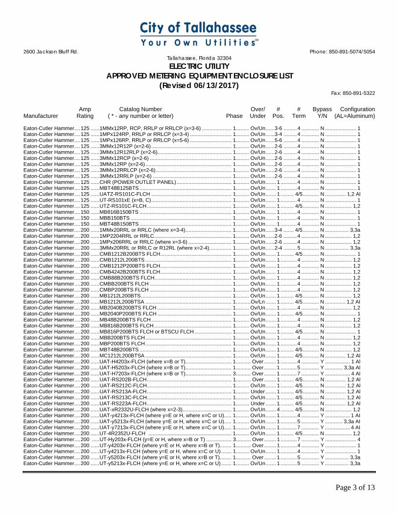
2600 Jackson Bluff Rd. Phone: 850-891-5074/5054
Tallahassee, Florida 32304 ELECTRIC UTILITY
APPROVED METERING EQUIPMENT ENCLOSURE LIST (Revised 06/13/2017)
Fax: 850-891-5322
Amp Catalog Number Over/ # # Bypass Configuration Manufacturer Rating ( * - any number or letter) Phase Under Pos. Term Y/N (AL=Aluminum)
Page 3 of 13
Eaton-Cutler Hammer .... 125 ...... 1MMx12RP, RCP, RRLP or RRLCP (x=3-6) .................... 1 ......... Ov/Un ......3-6 ......... 4 ............ N ..................... 1 Eaton-Cutler Hammer .... 125 ...... 1MPx124RP, RRLP or RRLCP (x=3-4) ............................ 1 ......... Ov/Un ......3-4 ......... 4 ............ N ..................... 1 Eaton-Cutler Hammer .... 125 ...... 1MPx126RP, RRLP or RRLCP (x=5-6) ............................ 1 ......... Ov/Un ......5-6 ......... 4 ............ N ..................... 1 Eaton-Cutler Hammer .... 125 ...... 3MMx12R12P (x=2-6) ...................................................... 1 ......... Ov/Un ......2-6 ......... 4 ............ N ..................... 1 Eaton-Cutler Hammer .... 125 ...... 3MMx12R12RLP (x=2-6).................................................. 1 ......... Ov/Un ......2-6 ......... 4 ............ N ..................... 1 Eaton-Cutler Hammer .... 125 ...... 3MMx12RCP (x=2-6) ....................................................... 1 ......... Ov/Un ......2-6 ......... 4 ............ N ..................... 1 Eaton-Cutler Hammer .... 125 ...... 3MMx12RP (x=2-6) .......................................................... 1 ......... Ov/Un ......2-6 ......... 4 ............ N ..................... 1 Eaton-Cutler Hammer .... 125 ...... 3MMx12RRLCP (x=2-6) ................................................... 1 ......... Ov/Un ......2-6 ......... 4 ............ N ..................... 1 Eaton-Cutler Hammer .... 125 ...... 3MMx12RRLP (x=2-6) ..................................................... 1 ......... Ov/Un ......2-6 ......... 4 ............ N ..................... 1 Eaton-Cutler Hammer .... 125 ...... CHR (POWER OUTLET PANEL) ..................................... 1 ......... Ov/Un ....... 1 ........... 4 ............ N ..................... 1 Eaton-Cutler Hammer .... 125 ...... MBT48B125BTS .............................................................. 1 ......... Ov/Un ....... 1 ........... 4 ............ N ..................... 1 Eaton-Cutler Hammer .... 125 ...... UATZ-RS101C-FLCH ...................................................... 1 ......... Ov/Un ....... 1 ......... 4/5 ........... N .............. 1,2 Al Eaton-Cutler Hammer .... 125 ...... UT-RS101xE (x=B, C) ...................................................... 1 ......... Ov/Un ....... 1 ........... 4 ............ N ..................... 1 Eaton-Cutler Hammer .... 125 ...... UTZ-RS101C-FLCH ......................................................... 1 ......... Ov/Un ....... 1 ......... 4/5 ........... N .................. 1,2 Eaton-Cutler Hammer .... 150 ...... MB816B150BTS .............................................................. 1 ......... Ov/Un ....... 1 ........... 4 ............ N ..................... 1 Eaton-Cutler Hammer .... 150 ...... MBB150BTS .................................................................... 1 ......... Ov/Un ....... 1 ........... 4 ............ N ..................... 1 Eaton-Cutler Hammer .... 150 ...... MBT48B150BTS .............................................................. 1 ......... Ov/Un ....... 1 ........... 4 ............ N ..................... 1 Eaton-Cutler Hammer .... 200 ...... 1MMx20RRL or RRLC (where x=3-4) ............................... 1 ......... Ov/Un ......3-4 ....... 4/5 ........... N ................ 3,3a Eaton-Cutler Hammer .... 200 ...... 1MP2204RRL or RRLC .................................................... 1 ......... Ov/Un ......2-6 ......... 4 ............ N .................. 1,2 Eaton-Cutler Hammer .... 200 ...... 1MPx206RRL or RRLC (where x=3-6) ............................. 1 ......... Ov/Un ......2-6 ......... 4 ............ N .................. 1,2 Eaton-Cutler Hammer .... 200 ...... 3MMx20RRL or RRLC or R12RL (where x=2-4) ............... 1 ......... Ov/Un ......2-4 ......... 5 ............ N ................ 3,3a Eaton-Cutler Hammer .... 200 ...... CMB1212B200BTS FLCH ................................................ 1 ......... Ov/Un ....... 1 ......... 4/5 ........... N ..................... 1 Eaton-Cutler Hammer .... 200 ...... CMB1212L200BTS .......................................................... 1 ......... Ov/Un ....... 1 ........... 4 ............ N .................. 1,2 Eaton-Cutler Hammer .... 200 ...... CMB1212P200BTS FLCH ................................................ 1 ......... Ov/Un ....... 1 ........... 4 ............ N .................. 1,2 Eaton-Cutler Hammer .... 200 ...... CMB4242B200BTS FLCH ................................................ 1 ......... Ov/Un ....... 1 ........... 4 ............ N .................. 1,2 Eaton-Cutler Hammer .... 200 ...... CMB88B200BTS FLCH .................................................... 1 ......... Ov/Un ....... 1 ........... 4 ............ N .................. 1,2 Eaton-Cutler Hammer .... 200 ...... CMBB200BTS FLCH ....................................................... 1 ......... Ov/Un ....... 1 ........... 4 ............ N .................. 1,2 Eaton-Cutler Hammer .... 200 ...... CMBP200BTS FLCH ....................................................... 1 ......... Ov/Un ....... 1 ........... 4 ............ N .................. 1,2 Eaton-Cutler Hammer .... 200 ...... MB1212L200BTS ............................................................. 1 ......... Ov/Un ....... 1 ......... 4/5 ........... N .................. 1,2 Eaton-Cutler Hammer .... 200 ...... MB1212L200BTSA .......................................................... 1 ..........Ov/Ln ....... 1 ......... 4/5 ........... N .............. 1,2 AI Eaton-Cutler Hammer .... 200 ...... MB2040B200BTS FLCH .................................................. 1 ......... Ov/Un ....... 1 ........... 4 ............ N .................. 1,2 Eaton-Cutler Hammer .... 200 ...... MB2040P200BTS FLCH .................................................. 1 ......... Ov/Un ....... 1 ......... 4/5 ........... N ..................... 1 Eaton-Cutler Hammer .... 200 ...... MB48B200BTS FLCH ...................................................... 1 ......... Ov/Un ....... 1 ........... 4 ............ N .................. 1,2 Eaton-Cutler Hammer .... 200 ...... MB816B200BTS FLCH .................................................... 1 ......... Ov/Un ....... 1 ........... 4 ............ N .................. 1,2 Eaton-Cutler Hammer .... 200 ...... MB816P200BTS FLCH or BTSCU FLCH ......................... 1 ......... Ov/Un ....... 1 ......... 4/5 ........... N ..................... 1 Eaton-Cutler Hammer .... 200 ...... MBB200BTS FLCH .......................................................... 1 ......... Ov/Un ....... 1 ........... 4 ............ N .................. 1,2 Eaton-Cutler Hammer .... 200 ...... MBP200BTS FLCH .......................................................... 1 ......... Ov/Un ....... 1 ........... 4 ............ N .................. 1,2 Eaton-Cutler Hammer .... 200 ...... MBT48B200BTS .............................................................. 1 ......... Ov/Un ....... 1 ......... 4/5 ........... N .................. 1,2 Eaton-Cutler Hammer .... 200 ...... MC1212L200BTSA .......................................................... 1 ......... Ov/Un ....... 1 ......... 4/5 ........... N .............. 1,2 Al Eaton-Cutler Hammer .... 200 ...... UAT-H4203x-FLCH (where x=B or T) ............................... 1 .......... Over ........ 1 ........... 4 ............ Y ................. 1 Al Eaton-Cutler Hammer .... 200 ...... UAT-H5203x-FLCH (where x=B or T) ............................... 1 .......... Over ........ 1 ........... 5 ............ Y ............ 3,3a Al Eaton-Cutler Hammer .... 200 ...... UAT-H7203x-FLCH (where x=B or T) ............................... 3 .......... Over ........ 1 ........... 7 ............ Y ................. 4 Al Eaton-Cutler Hammer .... 200 ...... UAT-RS202B-FLCH ......................................................... 1 .......... Over ........ 1 ......... 4/5 ........... N .............. 1,2 Al Eaton-Cutler Hammer .... 200 ...... UAT-RS212C-FLCH ......................................................... 1 ......... Ov/Un ....... 1 ......... 4/5 ........... N .............. 1,2 Al Eaton-Cutler Hammer .... 200 ...... UAT-RS213A-FLCH ......................................................... 1 ......... Under ....... 1 ......... 4/5 ........... N .............. 1,2 Al Eaton-Cutler Hammer .... 200 ...... UAT-RS213C-FLCH ......................................................... 1 ......... Ov/Un ....... 1 ......... 4/5 ........... N .............. 1,2 Al Eaton-Cutler Hammer .... 200 ...... UAT-RS223A-FLCH ......................................................... 1 ......... Under ....... 1 ......... 4/5 ........... N .............. 1,2 Al Eaton-Cutler Hammer .... 200 ...... UAT-xR2332U-FLCH (where x=2-3) ................................. 1 ......... Ov/Un ....... 4 ......... 4/5 ........... N .................. 1,2 Eaton-Cutler Hammer .... 200 ...... UAT-y4213x-FLCH (where y=E or H, where x=C or U) ..... 1 ......... Ov/Un ....... 1 ........... 4 ............ Y ................. 1 AI Eaton-Cutler Hammer .... 200 ...... UAT-y5213x-FLCH (where y=E or H, where x=C or U) ..... 1 ......... Ov/Un ....... 1 ........... 5 ............ Y ............ 3,3a AI Eaton-Cutler Hammer .... 200 ...... UAT-y7213x-FLCH (where y=E or H, where x=C or U) ..... 1 ......... Ov/Un ....... 1 ........... 7 ............ Y ................. 4 AI Eaton-Cutler Hammer .... 200 ...... UT-4R2352U-FLCH ........................................................ 1 ......... Ov/Un ....... 1 ......... 4/5 ........... N .................. 1,2 Eaton-Cutler Hammer .... 200 ..... UT-Hy203x-FLCH (y=E or H, where x=B or T) ................. 3 .......... Over ........ 1 ........... 7 ............ Y ..................... 4 Eaton-Cutler Hammer .... 200 ...... UT-y4203x-FLCH (where y=E or H, where x=B or T)........ 1 .......... Over ........ 1 ........... 4 ............ Y ..................... 1 Eaton-Cutler Hammer .... 200 ...... UT-y4213x-FLCH (where y=E or H, where x=C or U) ....... 1 ......... Ov/Un ....... 1 ........... 4 ............ Y ..................... 1 Eaton-Cutler Hammer .... 200 ...... UT-y5203x-FLCH (where y=E or H, where x=B or T)........ 1 .......... Over ........ 1 ........... 5 ............ Y ................ 3,3a Eaton-Cutler Hammer .... 200 ...... UT-y5213x-FLCH (where y=E or H, where x=C or U) ....... 1 ......... Ov/Un ....... 1 ........... 5 ............ Y ................ 3,3a
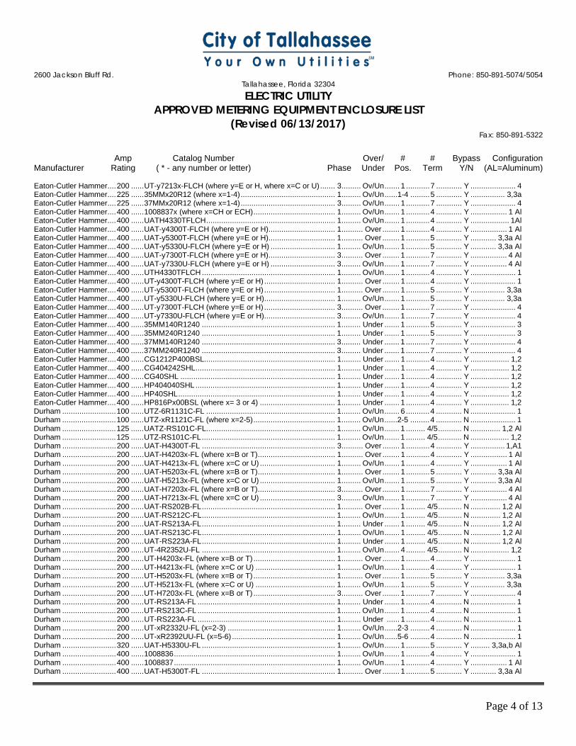
2600 Jackson Bluff Rd. Phone: 850-891-5074/5054
Tallahassee, Florida 32304 ELECTRIC UTILITY
APPROVED METERING EQUIPMENT ENCLOSURE LIST (Revised 06/13/2017)
Fax: 850-891-5322
Amp Catalog Number Over/ # # Bypass Configuration Manufacturer Rating ( * - any number or letter) Phase Under Pos. Term Y/N (AL=Aluminum)
Page 4 of 13
Eaton-Cutler Hammer .... 200 ...... UT-y7213x-FLCH (where y=E or H, where x=C or U) ....... 3 ......... Ov/Un ....... 1 ........... 7 ............ Y ..................... 4 Eaton-Cutler Hammer .... 225 ...... 35MMx20R12 (where x=1-4) ............................................ 1 ......... Ov/Un ......1-4 ......... 5 ............ Y ................ 3,3a Eaton-Cutler Hammer .... 225 ...... 37MMx20R12 (where x=1-4) ............................................ 3 ......... Ov/Un ....... 1 ........... 7 ............ Y ..................... 4 Eaton-Cutler Hammer .... 400 ...... 1008837x (where x=CH or ECH) ...................................... 1 ......... Ov/Un ....... 1 ........... 4 ............ Y ................. 1 Al Eaton-Cutler Hammer .... 400 ...... UATH4330TFLCH ............................................................ 1 ......... Ov/Un ....... 1 ........... 4 ............ Y .................. 1Al Eaton-Cutler Hammer .... 400 ...... UAT-y4300T-FLCH (where y=E or H) ............................... 1 .......... Over ........ 1 ........... 4 ............ Y ................. 1 Al Eaton-Cutler Hammer .... 400 ...... UAT-y5300T-FLCH (where y=E or H) ............................... 1 .......... Over ........ 1 ........... 5 ............ Y ............ 3,3a Al Eaton-Cutler Hammer .... 400 ...... UAT-y5330U-FLCH (where y=E or H) .............................. 1 ......... Ov/Un ....... 1 ........... 5 ............ Y ............ 3,3a Al Eaton-Cutler Hammer .... 400 ...... UAT-y7300T-FLCH (where y=E or H) ............................... 3 .......... Over ........ 1 ........... 7 ............ Y ................. 4 Al Eaton-Cutler Hammer .... 400 ...... UAT-y7330U-FLCH (where y=E or H) .............................. 3 ......... Ov/Un ....... 1 ........... 7 ............ Y ................. 4 Al Eaton-Cutler Hammer .... 400 ...... UTH4330TFLCH .............................................................. 1 ......... Ov/Un ....... 1 ........... 4 ............ Y ..................... 1 Eaton-Cutler Hammer .... 400 ...... UT-y4300T-FLCH (where y=E or H) ................................. 1 .......... Over ........ 1 ........... 4 ............ Y ..................... 1 Eaton-Cutler Hammer .... 400 ...... UT-y5300T-FLCH (where y=E or H) ................................. 1 .......... Over ........ 1 ........... 5 ............ Y ................ 3,3a Eaton-Cutler Hammer .... 400 ...... UT-y5330U-FLCH (where y=E or H) ................................. 1 ......... Ov/Un ....... 1 ........... 5 ............ Y ................ 3,3a Eaton-Cutler Hammer .... 400 ...... UT-y7300T-FLCH (where y=E or H) ................................. 3 .......... Over ........ 1 ........... 7 ............ Y ..................... 4 Eaton-Cutler Hammer .... 400 ...... UT-y7330U-FLCH (where y=E or H) ................................. 3 ......... Ov/Un ....... 1 ........... 7 ............ Y ..................... 4 Eaton-Cutler Hammer .... 400 ...... 35MM140R1240 .............................................................. 1 ......... Under ....... 1 ........... 5 ............ Y ..................... 3 Eaton-Cutler Hammer .... 400 ...... 35MM240R1240 .............................................................. 1 ......... Under ....... 1 ........... 5 ............ Y ..................... 3 Eaton-Cutler Hammer .... 400 ...... 37MM140R1240 .............................................................. 3 ......... Under ....... 1 ........... 7 ............ Y ..................... 4 Eaton-Cutler Hammer .... 400 ...... 37MM240R1240 .............................................................. 3 ......... Under ....... 1 ........... 7 ............ Y ..................... 4 Eaton-Cutler Hammer .... 400 ...... CG1212P400BSL............................................................. 1 ......... Under ....... 1 ........... 4 ............ Y .................. 1,2 Eaton-Cutler Hammer .... 400 ...... CG404242SHL ................................................................. 1 ......... Under ....... 1 ........... 4 ............ Y .................. 1,2 Eaton-Cutler Hammer .... 400 ...... CG40SHL ........................................................................ 1 ......... Under ....... 1 ........... 4 ............ Y .................. 1,2 Eaton-Cutler Hammer .... 400 ...... HP404040SHL ................................................................. 1 ......... Under ....... 1 ........... 4 ............ Y .................. 1,2 Eaton-Cutler Hammer .... 400 ...... HP40SHL ......................................................................... 1 ......... Under ....... 1 ........... 4 ............ Y .................. 1,2 Eaton-Cutler Hammer .... 400 ...... HP816Px00BSL (where x= 3 or 4) ................................... 1 ......... Under ....... 1 ........... 4 ............ Y .................. 1,2 Durham ......................... 100 ...... UTZ-6R1131C-FL ............................................................ 1 ......... Ov/Un ....... 6 ........... 4 ............ N ..................... 1 Durham ......................... 100 ...... UTZ-xR1121C-FL (where x=2-5) ...................................... 1 ......... Ov/Un ......2-5 ......... 4 ............ N ..................... 1 Durham ......................... 125 ...... UATZ-RS101C-FL ............................................................ 1 ......... Ov/Un ....... 1 ......... 4/5 ........... N .............. 1,2 Al Durham ......................... 125 ...... UTZ-RS101C-FL .............................................................. 1 ......... Ov/Un ....... 1 ......... 4/5 ........... N .................. 1,2 Durham ......................... 200 ...... UAT-H4300T-FL .............................................................. 3 .......... Over ........ 1 ........... 4 ............ Y ................ 1,A1 Durham ......................... 200 ...... UAT-H4203x-FL (where x=B or T) .................................... 1 .......... Over ........ 1 ........... 4 ............ Y ................. 1 Al Durham ......................... 200 ...... UAT-H4213x-FL (where x=C or U) ................................... 1 ......... Ov/Un ....... 1 ........... 4 ............ Y ................. 1 Al Durham ......................... 200 ...... UAT-H5203x-FL (where x=B or T) .................................... 1 .......... Over ........ 1 ........... 5 ............ Y ............ 3,3a Al Durham ......................... 200 ...... UAT-H5213x-FL (where x=C or U) ................................... 1 ......... Ov/Un ....... 1 ........... 5 ............ Y ............ 3,3a Al Durham ......................... 200 ...... UAT-H7203x-FL (where x=B or T) .................................... 3 .......... Over ........ 1 ........... 7 ............ Y ................. 4 Al Durham ......................... 200 ...... UAT-H7213x-FL (where x=C or U) ................................... 3 ......... Ov/Un ....... 1 ........... 7 ............ Y ................. 4 Al Durham ......................... 200 ...... UAT-RS202B-FL .............................................................. 1 .......... Over ........ 1 ......... 4/5 ........... N .............. 1,2 Al Durham ......................... 200 ...... UAT-RS212C-FL .............................................................. 1 ......... Ov/Un ....... 1 ......... 4/5 ........... N .............. 1,2 Al Durham ......................... 200 ...... UAT-RS213A-FL .............................................................. 1 ......... Under ....... 1 ......... 4/5 ........... N .............. 1,2 Al Durham ......................... 200 ...... UAT-RS213C-FL .............................................................. 1 ......... Ov/Un ....... 1 ......... 4/5 ........... N .............. 1,2 Al Durham ......................... 200 ...... UAT-RS223A-FL .............................................................. 1 ......... Under ....... 1 ......... 4/5 ........... N .............. 1,2 Al Durham ......................... 200 ...... UT-4R2352U-FL .............................................................. 1 ......... Ov/Un ....... 4 ......... 4/5 ........... N .................. 1,2 Durham ......................... 200 ...... UT-H4203x-FL (where x=B or T) ...................................... 1 .......... Over ........ 1 ........... 4 ............ Y ..................... 1 Durham ......................... 200 ...... UT-H4213x-FL (where x=C or U) ..................................... 1 ......... Ov/Un ....... 1 ........... 4 ............ Y ..................... 1 Durham ......................... 200 ...... UT-H5203x-FL (where x=B or T) ...................................... 1 .......... Over ........ 1 ........... 5 ............ Y ................ 3,3a Durham ......................... 200 ...... UT-H5213x-FL (where x=C or U) ..................................... 1 ......... Ov/Un ....... 1 ........... 5 ............ Y ................ 3,3a Durham ......................... 200 ...... UT-H7203x-FL (where x=B or T) ...................................... 3 .......... Over ........ 1 ........... 7 ............ Y ..................... 4 Durham ......................... 200 ...... UT-RS213A-FL ................................................................ 1 ......... Under ....... 1 ........... 4 ............ N ..................... 1 Durham ......................... 200 ...... UT-RS213C-FL ................................................................ 1 ......... Ov/Un ....... 1 ........... 4 ............ N ..................... 1 Durham ......................... 200 ...... UT-RS223A-FL ................................................................ 1 ......... Under ...... 1 ........... 4 ............ N ..................... 1 Durham ......................... 200 ...... UT-xR2332U-FL (x=2-3) .................................................. 1 ......... Ov/Un ......2-3 ......... 4 ............ N ..................... 1 Durham ......................... 200 ...... UT-xR2392UU-FL (x=5-6) ................................................ 1 ......... Ov/Un ......5-6 ......... 4 ............ N ..................... 1 Durham ......................... 320 ...... UAT-H5330U-FL .............................................................. 1 ......... Ov/Un ....... 1 ........... 5 ............ Y ......... 3,3a,b Al Durham ......................... 400 ...... 1008836 ........................................................................... 1 ......... Ov/Un ....... 1 ........... 4 ............ Y ..................... 1 Durham ......................... 400 ...... 1008837 ........................................................................... 1 ......... Ov/Un ....... 1 ........... 4 ............ Y ................. 1 Al Durham ......................... 400 ...... UAT-H5300T-FL .............................................................. 1 .......... Over ........ 1 ........... 5 ............ Y ............ 3,3a Al

2600 Jackson Bluff Rd. Phone: 850-891-5074/5054
Tallahassee, Florida 32304 ELECTRIC UTILITY
APPROVED METERING EQUIPMENT ENCLOSURE LIST (Revised 06/13/2017)
Fax: 850-891-5322
Amp Catalog Number Over/ # # Bypass Configuration Manufacturer Rating ( * - any number or letter) Phase Under Pos. Term Y/N (AL=Aluminum)
Page 5 of 13
Durham ......................... 400 ...... UAT-H5330U-FL .............................................................. 1 ......... Ov/Un ....... 1 ........... 5 ............ Y ............ 3,3a Al Durham ......................... 400 ...... UAT-H7300T-FL .............................................................. 3 .......... Over ........ 1 ........... 7 ............ Y ................. 4 Al Durham ......................... 400 ...... UAT-H7330U-FL .............................................................. 3 ......... Ov/Un ....... 1 ........... 7 ............ Y ................. 4 Al Durham ......................... 400 ...... UT-H4300T-FL ................................................................. 1 .......... Over ........ 1 ........... 4 ............ Y ..................... 1 Durham ......................... 400 ...... UT-H5300T-FL ................................................................. 1 .......... Over ........ 1 ........... 5 ............ Y ................ 3,3a Durham ......................... 400 ...... UT-H5330U-FL ................................................................ 1 ......... Ov/Un ....... 1 ........... 5 ............ Y ................ 3,3a Durham ......................... 400 ...... UT-H7300T-FL ................................................................. 3 .......... Over ........ 1 ........... 7 ............ Y ..................... 4 Durham ......................... 400 ...... UT-H7330U-FL ................................................................ 3 ......... Ov/Un ....... 1 ........... 7 ............ Y ..................... 4 Elec. Prod. ..................... 100 ...... RVP-xxxx-FPL ................................................................. 1 ......... Under ....... 1 ........... 4 ............ N ..................... 1 Elec. Prod. ..................... 200 ...... MHP-xxxx-FPL ................................................................. 1 ......... Under ....... 1 ........... 4 ............ N ..................... 1 Emerson ........................ 125 ...... MESBGFXLW11FBZ1...................................................... 1 ......... Under ....... 1 ........... 5 ............ Y ................... 3a Emerson ........................ 125 ...... MESBGFXLW11FBZ1P ................................................... 1 ......... Under ....... 1 ........... 5 ............ Y ................... 3a Emerson ........................ 125 ...... MESBGFXLW11KBZ1 ..................................................... 1 ......... Under ....... 1 ........... 5 ............ Y ................... 3a Emerson ........................ 125 ...... MESBGFXLW11KBZ1P ................................................... 1 ......... Under ....... 1 ........... 5 ............ Y ................... 3a Emerson ........................ 200 ...... MESBAATLW11FBZ1 ...................................................... 1 ......... Under ....... 1 ........... 5 ............ Y ................... 3a Emerson ........................ 200 ...... MESBAATLW11FBZ1P .................................................... 1 ......... Under ....... 1 ........... 5 ............ Y ................... 3a Emerson ........................ 200 ...... MESBAATLW11KBZ1 ...................................................... 1 ......... Under ....... 1 ........... 5 ............ Y ................... 3a Emerson ........................ 200 ...... MESBAATLW11KBZ1P ................................................... 1 ......... Under ....... 1 ........... 5 ............ Y ................... 3a General Electric ............. 100 ...... TM10RMCFMG ................................................................ 1 ......... Ov/Un ....... 1 ........... 4 ............ N ..................... 1 General Electric ............. 100 ...... UTZ-6R1131CFLGE ........................................................ 1 ......... Ov/Un ....... 6 ........... 4 ............ N ..................... 1 General Electric ............. 100 ...... UTZ-xR1121CFLGE (x=2-5) ............................................ 1 ......... Ov/Un ....... 6 ......... 4/5 ........... N .................. 1,2 General Electric ............. 125 ...... TM12RMCFMG ................................................................ 1 ......... Ov/Un ....... 1 ........... 4 ............ N ..................... 1 General Electric ............. 125 ...... TMMR2212RF ................................................................. 1 ......... Under ....... 2 ......... 4/5 ........... N .................. 1,2 General Electric ............. 125 ...... TMM4x12RF (x=3-4) ........................................................ 1 ......... Under ......3-4 ....... 4/5 ........... N .................. 1,2 General Electric ............. 125 ...... TMM6x12RF (x=5-6) ........................................................ 1 ......... Under ......5-6 ....... 4/5 ........... N .................. 1,2 General Electric ............. 125 ...... TMP8x12RF (x=2-6)......................................................... 1 ......... Under ......2-6 ....... 4/5 ........... N .................. 1,2 General Electric ............. 125 ...... TMPRI12x12RF (x=2-6) ................................................... 1 ......... Ov/Un ......2-6 ......... 5 ............ Y ................ 3,3a General Electric ............. 125 ...... TMPR8x12RF (x=2-6) ...................................................... 1 ......... Under ......2-6 ....... 4/5 ........... N .................. 1,2 General Electric ............. 125 ...... TMMR4x12R (where x=3-4) ............................................. 1 ......... Under ......3-4 ....... 4/5 ........... N .................. 1,2 General Electric ............. 125 ...... TMMR6x12R (where x=5-6) ............................................. 1 ......... Under ......5-6 ....... 4/5 ........... N .................. 1,2 General Electric ............. 125 ...... TMPR8x12R (where x=2-6) .............................................. 1 ......... Under ......2-6 ....... 4/5 ........... N .................. 1,2 General Electric ............. 150 ...... TM15RMCFMG ................................................................ 1 ......... Ov/Un ....... 1 ........... 4 ............ N ..................... 1 General Electric ............. 150 ...... TSMR415CSFLFMG ........................................................ 1 ......... Ov/Un ....... 1 ........... 5 ............ N ..................... 2 General Electric ............. 150 ...... TSMR815CSFLFMG ........................................................ 1 ......... Ov/Un ....... 1 ........... 5 ............ N ..................... 2 General Electric ............. 200 ..... TM20RMCFMG ................................................................ 1 ......... Ov/Un ....... 1 ........... 4 ............ N ..................... 1 General Electric ............. 200 ...... TMM6x20RF (x=3-5) ........................................................ 1 ......... Under ......3-5 ....... 4/5 ........... N .................. 1,2 General Electric ............. 200 ...... TMMR4220RF ................................................................. 1 ......... Ov/Un ....... 2 ........... 4 ............ N .................. 1,2 General Electric ............. 200 ...... TMMR6x20RF (x=3-6) ..................................................... 1 ......... Under ......3-6 ....... 4/5 ........... N .................. 1,2 General Electric ............. 200 ...... TMP12x20RF (x=2-4) ....................................................... 1 ......... Ov/UN ......2-4 ......... 5 ............ Y ................ 3,3a General Electric ............. 200 ...... TMP8x20RF (x=2-4)......................................................... 1 ......... Under ......2-4 ....... 4/5 ........... N .................. 1,2 General Electric ............. 200 ...... TMPR12x20RF (x=2-5) .................................................... 1 ......... Ov/UN ......2-4 ......... 5 ............ Y ................ 3,3a General Electric ............. 200 ...... TMP12x20RF (x=2-4) ....................................................... 1 ......... Ov/UN ......2-4 ......... 5 ............ Y ................ 3,3a General Electric ............. 200 ...... TMPR312x22RF (x=1-4) .................................................. 3 ......... Ov/UN ......1-4 ......... 7 ............ Y ..................... 4 General Electric ............. 200 ...... TMP8x20RF (x=3-4)......................................................... 1 ......... Ov/UN .....3-4 ......... 4 ............ N ..................... 1 General Electric ............. 200 ...... TMPR12x20RF (x=4-5) .................................................... 1 ......... Ov/UN ......4-5 ......... 5 ............ N ..................... 2 General Electric ............. 200 ...... TMPR8x20RF (x=2-5) ...................................................... 1 ......... Under ......2-5 ....... 4/5 ........... N .................. 1,2 General Electric ............. 200 ...... TSLR1220FSAL ............................................................... 1 ......... Ov/Un ....... 1 ........... 4 ............ N ................ 1,A1 General Electric ............. 200 ...... TSMF420CSFL ................................................................ 1 ......... Ov/Un ....... 1 ......... 4/5 ........... N .................. 1,2 General Electric ............. 200 ...... TSMF820CSFL ................................................................ 1 ......... Ov/Un ....... 1 ......... 4/5 ........... N .................. 1,2 General Electric ............. 200 ...... TSMR2020CSCUFMG ..................................................... 1 ......... Ov/Un ....... 1 ........... 4 ............ N ..................... 1 General Electric ............. 200 ...... TSMRx20CSFLFMG (where x =4 or 8) ............................ 1 ......... Ov/Un ....... 1 ........... 4 ............ N ..................... 1 General Electric ............. 200 ...... UAT-H4203x-FLGE (x=B or T) ......................................... 1 .......... Over ........ 1 ........... 4 ............ Y ................. 1 Al General Electric ............. 200 ...... UAT-H4213x-FLGE (x=C or U)......................................... 1 ......... Ov/Un ....... 1 ........... 4 ............ Y ................. 1 Al General Electric ............. 200 ...... UAT-H5203x-FLGE (x=B or T) ......................................... 1 .......... Over ........ 1 ........... 5 ............ Y ......... 3,3a,b Al General Electric ............. 200 ...... UAT-H5213x-FLGE (x=C or U)......................................... 1 ......... Ov/Un ....... 1 ........... 5 ............ Y ......... 3,3a,b Al General Electric ............. 200 ...... UAT-H7203x-FLGE (x=B or T) ......................................... 3 .......... Over ........ 1 ........... 7 ............ Y ................. 4 Al General Electric ............. 200 ...... UAT-H7213x-FLGE (x=C or U)......................................... 1 ......... Ov/Un ....... 1 ........... 7 ............ Y ................. 4 Al
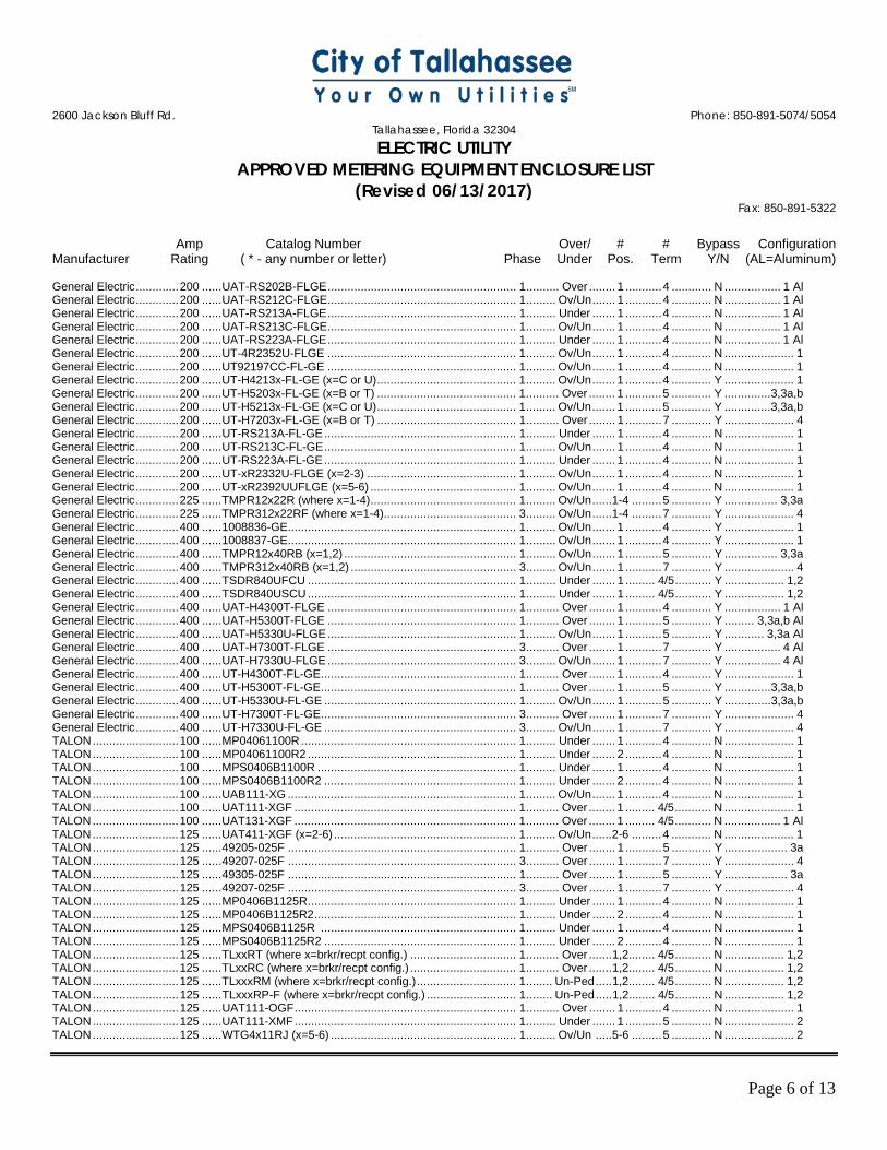
2600 Jackson Bluff Rd. Phone: 850-891-5074/5054
Tallahassee, Florida 32304 ELECTRIC UTILITY
APPROVED METERING EQUIPMENT ENCLOSURE LIST (Revised 06/13/2017)
Fax: 850-891-5322
Amp Catalog Number Over/ # # Bypass Configuration Manufacturer Rating ( * - any number or letter) Phase Under Pos. Term Y/N (AL=Aluminum)
Page 6 of 13
General Electric ............. 200 ...... UAT-RS202B-FLGE ......................................................... 1 .......... Over ........ 1 ........... 4 ............ N ................. 1 Al General Electric ............. 200 ...... UAT-RS212C-FLGE ......................................................... 1 ......... Ov/Un ....... 1 ........... 4 ............ N ................. 1 Al General Electric ............. 200 ...... UAT-RS213A-FLGE ......................................................... 1 ......... Under ....... 1 ........... 4 ............ N ................. 1 Al General Electric ............. 200 ...... UAT-RS213C-FLGE ......................................................... 1 ......... Ov/Un ....... 1 ........... 4 ............ N ................. 1 Al General Electric ............. 200 ...... UAT-RS223A-FLGE ......................................................... 1 ......... Under ....... 1 ........... 4 ............ N ................. 1 Al General Electric ............. 200 ...... UT-4R2352U-FLGE ......................................................... 1 ......... Ov/Un ....... 1 ........... 4 ............ N ..................... 1 General Electric ............. 200 ...... UT92197CC-FL-GE ......................................................... 1 ......... Ov/Un ....... 1 ........... 4 ............ N ..................... 1 General Electric ............. 200 ...... UT-H4213x-FL-GE (x=C or U) .......................................... 1 ......... Ov/Un ....... 1 ........... 4 ............ Y ..................... 1 General Electric ............. 200 ...... UT-H5203x-FL-GE (x=B or T) .......................................... 1 .......... Over ........ 1 ........... 5 ............ Y .............. 3,3a,b General Electric ............. 200 ...... UT-H5213x-FL-GE (x=C or U) .......................................... 1 ......... Ov/Un ....... 1 ........... 5 ............ Y .............. 3,3a,b General Electric ............. 200 ...... UT-H7203x-FL-GE (x=B or T) .......................................... 1 .......... Over ........ 1 ........... 7 ............ Y ..................... 4 General Electric ............. 200 ...... UT-RS213A-FL-GE .......................................................... 1 ......... Under ....... 1 ........... 4 ............ N ..................... 1 General Electric ............. 200 ...... UT-RS213C-FL-GE .......................................................... 1 ......... Ov/Un ....... 1 ........... 4 ............ N ..................... 1 General Electric ............. 200 ...... UT-RS223A-FL-GE .......................................................... 1 ......... Under ....... 1 ........... 4 ............ N ..................... 1 General Electric ............. 200 ...... UT-xR2332U-FLGE (x=2-3) ............................................. 1 ......... Ov/Un ....... 1 ........... 4 ............ N ..................... 1 General Electric ............. 200 ...... UT-xR2392UUFLGE (x=5-6) ............................................ 1 ......... Ov/Un ....... 1 ........... 4 ............ N ..................... 1 General Electric ............. 225 ...... TMPR12x22R (where x=1-4) ............................................ 1 ......... Ov/Un ......1-4 ......... 5 ............ Y ................ 3,3a General Electric ............. 225 ...... TMPR312x22RF (where x=1-4) ........................................ 3 ......... Ov/Un ......1-4 ......... 7 ............ Y ..................... 4 General Electric ............. 400 ...... 1008836-GE..................................................................... 1 ......... Ov/Un ....... 1 ........... 4 ............ Y ..................... 1 General Electric ............. 400 ...... 1008837-GE..................................................................... 1 ......... Ov/Un ....... 1 ........... 4 ............ Y ..................... 1 General Electric ............. 400 ...... TMPR12x40RB (x=1,2) .................................................... 1 ......... Ov/Un ....... 1 ........... 5 ............ Y ................ 3,3a General Electric ............. 400 ...... TMPR312x40RB (x=1,2) .................................................. 3 ......... Ov/Un ....... 1 ........... 7 ............ Y ..................... 4 General Electric ............. 400 ...... TSDR840UFCU ............................................................... 1 ......... Under ....... 1 ......... 4/5 ........... Y .................. 1,2 General Electric ............. 400 ...... TSDR840USCU ............................................................... 1 ......... Under ....... 1 ......... 4/5 ........... Y .................. 1,2 General Electric ............. 400 ...... UAT-H4300T-FLGE ......................................................... 1 .......... Over ........ 1 ........... 4 ............ Y ................. 1 Al General Electric ............. 400 ...... UAT-H5300T-FLGE ......................................................... 1 .......... Over ........ 1 ........... 5 ............ Y ......... 3,3a,b Al General Electric ............. 400 ...... UAT-H5330U-FLGE ......................................................... 1 ......... Ov/Un ....... 1 ........... 5 ............ Y ............ 3,3a Al General Electric ............. 400 ...... UAT-H7300T-FLGE ......................................................... 3 .......... Over ........ 1 ........... 7 ............ Y ................. 4 Al General Electric ............. 400 ...... UAT-H7330U-FLGE ......................................................... 3 ......... Ov/Un ....... 1 ........... 7 ............ Y ................. 4 Al General Electric ............. 400 ...... UT-H4300T-FL-GE ........................................................... 1 .......... Over ........ 1 ........... 4 ............ Y ..................... 1 General Electric ............. 400 ...... UT-H5300T-FL-GE ........................................................... 1 .......... Over ........ 1 ........... 5 ............ Y .............. 3,3a,b General Electric ............. 400 ...... UT-H5330U-FL-GE .......................................................... 1 ......... Ov/Un ....... 1 ........... 5 ............ Y .............. 3,3a,b General Electric ............. 400 ...... UT-H7300T-FL-GE ........................................................... 3 .......... Over ........ 1 ........... 7 ............ Y ..................... 4 General Electric ............. 400 ...... UT-H7330U-FL-GE .......................................................... 3 ......... Ov/Un ....... 1 ........... 7 ............ Y ..................... 4 TALON .......................... 100 ...... MP04061100R ................................................................. 1 ......... Under ....... 1 ........... 4 ............ N ..................... 1 TALON .......................... 100 ...... MP04061100R2 ............................................................... 1 ......... Under ....... 2 ........... 4 ............ N ..................... 1 TALON .......................... 100 ...... MPS0406B1100R ............................................................ 1 ......... Under ....... 1 ........... 4 ............ N ..................... 1 TALON .......................... 100 ...... MPS0406B1100R2 .......................................................... 1 ......... Under ....... 2 ........... 4 ............ N ..................... 1 TALON .......................... 100 ...... UAB111-XG ..................................................................... 1 ......... Ov/Un ....... 1 ........... 4 ............ N ..................... 1 TALON .......................... 100 ...... UAT111-XGF ................................................................... 1 .......... Over ........ 1 ......... 4/5 ........... N ..................... 1 TALON .......................... 100 ...... UAT131-XGF ................................................................... 1 .......... Over ........ 1 ......... 4/5 ........... N ................. 1 Al TALON .......................... 125 ...... UAT411-XGF (x=2-6) ....................................................... 1 ......... Ov/Un ......2-6 ......... 4 ............ N ..................... 1 TALON .......................... 125 ...... 49205-025F ..................................................................... 1 .......... Over ........ 1 ........... 5 ............ Y ................... 3a TALON .......................... 125 ...... 49207-025F ..................................................................... 3 .......... Over ........ 1 ........... 7 ............ Y ..................... 4 TALON .......................... 125 ...... 49305-025F ..................................................................... 1 .......... Over ........ 1 ........... 5 ............ Y ................... 3a TALON .......................... 125 ...... 49207-025F ..................................................................... 3 .......... Over ........ 1 ........... 7 ............ Y ..................... 4 TALON .......................... 125 ...... MP0406B1125R ............................................................... 1 ......... Under ....... 1 ........... 4 ............ N ..................... 1 TALON .......................... 125 ...... MP0406B1125R2 ............................................................. 1 ......... Under ....... 2 ........... 4 ............ N ..................... 1 TALON .......................... 125 ...... MPS0406B1125R ........................................................... 1 ......... Under ....... 1 ........... 4 ............ N ..................... 1 TALON .......................... 125 ...... MPS0406B1125R2 .......................................................... 1 ......... Under ....... 2 ........... 4 ............ N ..................... 1 TALON .......................... 125 ...... TLxxRT (where x=brkr/recpt config.) ................................ 1 .......... Over ....... 1,2........ 4/5 ........... N .................. 1,2 TALON .......................... 125 ...... TLxxRC (where x=brkr/recpt config.) ................................ 1 .......... Over ....... 1,2........ 4/5 ........... N .................. 1,2 TALON .......................... 125 ...... TLxxxRM (where x=brkr/recpt config.) .............................. 1 ........ Un-Ped ..... 1,2........ 4/5 ........... N .................. 1,2 TALON .......................... 125 ...... TLxxxRP-F (where x=brkr/recpt config.) ........................... 1 ........ Un-Ped ..... 1,2........ 4/5 ........... N .................. 1,2 TALON .......................... 125 ...... UAT111-OGF ................................................................... 1 .......... Over ........ 1 ........... 4 ............ N ..................... 1 TALON .......................... 125 ...... UAT111-XMF ................................................................... 1 ......... Under ....... 1 ........... 5 ............ N ..................... 2 TALON .......................... 125 ...... WTG4x11RJ (x=5-6) ........................................................ 1 ......... Ov/Un .....5-6 ......... 5 ............ N ..................... 2
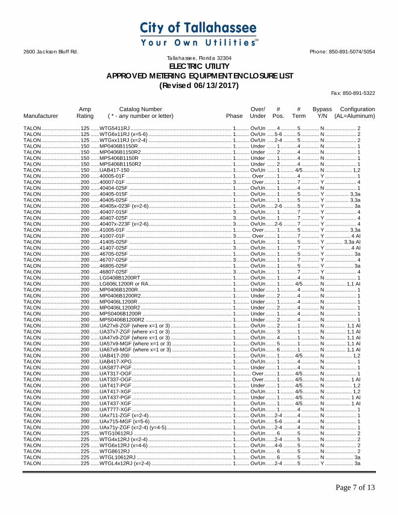
2600 Jackson Bluff Rd. Phone: 850-891-5074/5054
Tallahassee, Florida 32304 ELECTRIC UTILITY
APPROVED METERING EQUIPMENT ENCLOSURE LIST (Revised 06/13/2017)
Fax: 850-891-5322
Amp Catalog Number Over/ # # Bypass Configuration Manufacturer Rating ( * - any number or letter) Phase Under Pos. Term Y/N (AL=Aluminum)
Page 7 of 13
TALON .......................... 125 ...... WTG5411RJ .................................................................... 1 ......... Ov/Un ...... 4 ........... 5 ............ N ..................... 2 TALON .......................... 125 ...... WTG6x11RJ (x=5-6) ........................................................ 1 ......... Ov/Un .....5-6 ......... 5 ............ N ..................... 2 TALON .......................... 125 ...... WTGxx11RJ (x=2-4) ........................................................ 1 ......... Ov/Un .....2-4 ......... 5 ............ N ..................... 2 TALON .......................... 150 ...... MP0406B1150R ............................................................... 1 ......... Under ...... 1 ........... 4 ............ N ..................... 1 TALON .......................... 150 ...... MP0406B1150R2 ............................................................. 1 ......... Under ...... 2 ........... 4 ............ N ..................... 1 TALON .......................... 150 ...... MPS406B1150R ............................................................. 1 ......... Under ...... 1 ........... 4 ............ N ..................... 1 TALON .......................... 150 ...... MPS406B1150R2 ............................................................ 1 ......... Under ...... 2 ........... 4 ............ N ..................... 1 TALON .......................... 150 ...... UAB417-150 .................................................................... 1 ......... Ov/Un ...... 1 ......... 4/5 ........... N .................. 1,2 TALON .......................... 200 ...... 40005-01F ....................................................................... 1 .......... Over ........ 1 ........... 4 ............ Y ..................... 1 TALON .......................... 200 ...... 40007-01F ....................................................................... 3 .......... Over ........ 1 ........... 7 ............ Y ..................... 4 TALON .......................... 200 ...... 40404-025F ..................................................................... 1 ......... Ov/Un ....... 1 ........... 4 ............ N ..................... 1 TALON .......................... 200 ...... 40405-015F ..................................................................... 1 ......... Ov/Un ....... 1 ........... 5 ............ Y ................ 3,3a TALON .......................... 200 ...... 40405-025F ..................................................................... 1 ......... Ov/Un ....... 1 ........... 5 ............ Y ................ 3,3a TALON .......................... 200 ...... 40405x-023F (x=2-6) ........................................................ 1 ......... Ov/Un ......2-6 ......... 5 ............ Y ................... 3a TALON .......................... 200 ...... 40407-015F ..................................................................... 3 ......... Ov/Un ....... 1 ........... 7 ............ Y ..................... 4 TALON .......................... 200 ...... 40407-025F ..................................................................... 3 ......... Ov/Un ....... 1 ........... 7 ............ Y ..................... 4 TALON .......................... 200 ...... 40407x-223F (x=2-6) ........................................................ 3 ......... Ov/Un ......2-6 ......... 7 ............ Y ..................... 4 TALON .......................... 200 ...... 41005-01F ....................................................................... 1 .......... Over ........ 1 ........... 5 ............ Y ................ 3,3a TALON .......................... 200 ...... 41007-01F ....................................................................... 3 .......... Over ........ 1 ........... 7 ............ Y ................. 4 Al TALON .......................... 200 ...... 41405-025F ..................................................................... 1 ......... Ov/Un ....... 1 ........... 5 ............ Y ............ 3,3a Al TALON .......................... 200 ...... 41407-025F ..................................................................... 3 ......... Ov/Un ....... 1 ........... 7 ............ Y ................. 4 Al TALON .......................... 200 ...... 46705-025F ..................................................................... 1 ......... Ov/Un ....... 1 ........... 5 ............ Y ................... 3a TALON .......................... 200 ...... 46707-025F ..................................................................... 3 ......... Ov/Un ....... 1 ........... 7 ............ Y ..................... 4 TALON .......................... 200 ...... 46805-025F ..................................................................... 1 ......... Ov/Un ....... 1 ........... 5 ............ Y ................... 3a TALON .......................... 200 ...... 46807-025F ..................................................................... 3 ......... Ov/Un ....... 1 ........... 7 ............ Y ..................... 4 TALON .......................... 200 ...... LG0408B1200RT ............................................................. 1 ......... Ov/Un ....... 1 ........... 4 ............ N ..................... 1 TALON .......................... 200 ...... LG606L1200R or RA ........................................................ 1 ......... Ov/Un ....... 1 ......... 4/5 ........... N .............. 1,1 AI TALON .......................... 200 ...... MP0406B1200R ............................................................... 1 ......... Under ....... 1 ........... 4 ............ N ..................... 1 TALON .......................... 200 ...... MP0406B1200R2 ............................................................. 1 ......... Under ....... 2 ........... 4 ............ N ..................... 1 TALON .......................... 200 ...... MP0406L1200R ............................................................... 1 ......... Under ....... 1 ........... 4 ............ N ..................... 1 TALON .......................... 200 ...... MP0406L1200R2 ............................................................. 1 ......... Under ....... 2 ........... 4 ............ N ..................... 1 TALON .......................... 200 ...... MPS0406B1200R ............................................................ 1 ......... Under ....... 1 ........... 4 ............ N ..................... 1 TALON .......................... 200 ...... MPS0406B1200R2 .......................................................... 1 ......... Under ....... 2 ........... 4 ............ N ..................... 1 TALON .......................... 200 ...... UA27x6-ZGF (where x=1 or 3) ......................................... 1 ......... Ov/Un ...... 2 ........... 1 ............ N .............. 1,1 Al TALON .......................... 200 ...... UA37x7-ZGF (where x=1 or 3) ......................................... 1 ......... Ov/Un ....... 3 ........... 1 ............ N .............. 1,1 Al TALON ......................... 200 ...... UA47x9-ZGF (where x=1 or 3) ......................................... 1 ......... Ov/Un ....... 4 ........... 1 ............ N .............. 1,1 Al TALON .......................... 200 ...... UA57x9-MGF (where x=1 or 3) ........................................ 1 ......... Ov/Un ....... 5 ........... 1 ............ N .............. 1,1 Al TALON .......................... 200 ...... UA67x9-MGF (where x=1 or 3) ........................................ 1 ......... Ov/Un ....... 6 ........... 1 ............ N .............. 1,1 Al TALON .......................... 200 ...... UAB417-200 .................................................................... 1 ......... Ov/Un ....... 1 ......... 4/5 ........... N .................. 1,2 TALON .......................... 200 ...... UAB417-XPG ................................................................... 1 ......... Ov/Un ....... 1 ........... 4 ............ N ..................... 1 TALON .......................... 200 ...... UAS877-PGF ................................................................... 1 ......... Under ....... 1 ........... 4 ............ N ..................... 1 TALON .......................... 200 ...... UAT317-OGF ................................................................... 1 .......... Over ........ 1 ......... 4/5 ........... N ..................... 1 TALON .......................... 200 ...... UAT337-OGF ................................................................... 1 .......... Over ........ 1 ......... 4/5 ........... N ................. 1 Al TALON .......................... 200 ...... UAT417-PGF ................................................................... 1 ......... Under ....... 1 ......... 4/5 ........... N .................. 1,2 TALON .......................... 200 ...... UAT417-XGF ................................................................... 1 ......... Ov/Un ....... 1 ......... 4/5 ........... N .................. 1,2 TALON .......................... 200 ...... UAT437-PGF ................................................................... 1 ......... Under ....... 1 ......... 4/5 ........... N ................. 1 Al TALON .......................... 200 ...... UAT437-XGF ................................................................... 1 ......... Ov/Un ....... 1 ......... 4/5 ........... N ................. 1 Al TALON .......................... 200 ...... UAT777-XGF ................................................................... 1 ......... Ov/Un ....... 1 ........... 4 ............ N ..................... 1 TALON .......................... 200 ...... UAx711-ZGF (x=2-4) ........................................................ 1 ......... Ov/Un ......2-4 ......... 4 ............ N ..................... 1 TALON .......................... 200 ...... UAx715-MGF (x=5-6) ....................................................... 1 ......... Ov/Un ......5-6 ......... 4 ............ N ..................... 1 TALON .......................... 200 ...... UAx71y-ZGF (x=2-4) (y=4-5) ............................................ 1 ......... Ov/Un ......2-4 ......... 4 ............ N ..................... 1 TALON .......................... 225 ...... WTG10612RJ .................................................................. 1 ......... Ov/Un ....... 6 ........... 5 ............ N ..................... 2 TALON .......................... 225 ...... WTG4x12RJ (x=2-4) ........................................................ 1 ......... Ov/Un ......2-4 ......... 5 ............ N ..................... 2 TALON .......................... 225 ...... WTG6x12RJ (x=4-6) ........................................................ 1 ......... Ov/Un ......4-6 ......... 5 ............ N ..................... 2 TALON .......................... 225 ...... WTG8612RJ .................................................................... 1 ......... Ov/Un ....... 6 ........... 5 ............ N ..................... 2 TALON .......................... 225 ...... WTGL10612RJ ................................................................ 1 ......... Ov/Un ....... 6 ........... 5 ............ N ................... 3a TALON .......................... 225 ...... WTGL4x12RJ (x=2-4) ...................................................... 1 ......... Ov/Un ......2-4 ......... 5 ............ Y ................... 3a
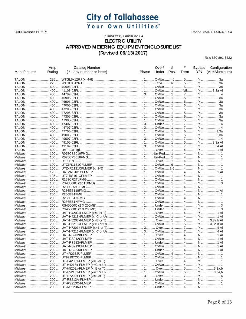
2600 Jackson Bluff Rd. Phone: 850-891-5074/5054
Tallahassee, Florida 32304 ELECTRIC UTILITY
APPROVED METERING EQUIPMENT ENCLOSURE LIST (Revised 06/13/2017)
Fax: 850-891-5322
Amp Catalog Number Over/ # # Bypass Configuration Manufacturer Rating ( * - any number or letter) Phase Under Pos. Term Y/N (AL=Aluminum)
Page 8 of 13
TALON .......................... 225 ...... WTGL6x12RJ (x=4-6) ...................................................... 1 ......... Ov/Un ......4-6 ......... 5 ............ Y ................... 3a TALON .......................... 225 ...... WTGL8612RJ .................................................................. 1 ........... Ov/ ......... 6 ........... 5 ............ Y ................... 3a TALON .......................... 400 ...... 40905-02FL ..................................................................... 1 ......... Ov/Un ....... 1 ........... 5 ............ Y ................... 3a TALON .......................... 400 ...... 41105-02FL ..................................................................... 1 ......... Ov/Un ....... 1 ......... 4/5 ........... Y ............ 3,3a Al TALON .......................... 400 ...... 44707-02FL ..................................................................... 3 ......... Ov/Un ....... 1 ........... 7 ............ Y ..................... 4 TALON .......................... 400 ...... 40905-02FL ..................................................................... 1 ......... Ov/Un ....... 1 ........... 5 ............ Y ................... 3a TALON .......................... 400 ...... 46905-02FL ..................................................................... 1 ......... Ov/Un ....... 1 ........... 5 ............ Y ................... 3a TALON .......................... 400 ...... 47005-02FL ..................................................................... 1 ......... Ov/Un ....... 1 ........... 5 ............ Y ................... 3a TALON .......................... 400 ...... 47205-02FL ..................................................................... 1 ......... Ov/Un ....... 1 ........... 5 ............ Y ................... 3a TALON .......................... 400 ...... 47205-82FL ..................................................................... 1 ......... Ov/Un ....... 1 ........... 5 ............ Y ................... 3a TALON .......................... 400 ...... 47305-02FL ..................................................................... 1 ......... Ov/Un ....... 1 ........... 5 ............ Y ................... 3a TALON .......................... 400 ...... 47305-82FL ..................................................................... 1 ......... Ov/Un ....... 1 ........... 5 ............ Y ................... 3a TALON .......................... 400 ...... 47407-02FL ..................................................................... 3 ......... Under ....... 1 ........... 7 ............ Y ..................... 4 TALON .......................... 400 ...... 44707-02FL ..................................................................... 3 ......... Ov/Un ....... 1 ........... 7 ............ Y ..................... 4 TALON .......................... 400 ...... 47705-02FL ..................................................................... 1 ......... Ov/Un ....... 1 ........... 5 ............ Y ................ 3,3a TALON .......................... 400 ...... 49005-02FL ..................................................................... 1 ......... Ov/Un ....... 1 ........... 5 ............ Y ................ 3,3a TALON .......................... 400 ...... 49007-02FL ..................................................................... 3 ......... Ov/Un ....... 1 ........... 7 ............ Y ..................... 4 TALON .......................... 400 ...... 49105-02FL ..................................................................... 1 ......... Ov/Un ....... 1 ........... 5 ............ Y ............ 3,3a Al TALON .......................... 400 ...... 49107-02FL ..................................................................... 3 ......... Ov/Un ....... 1 ........... 7 ............ Y ................. 4 Al TALON .......................... 400 ...... UAT-131-xgf..................................................................... 1 .......... Over ........ 1 ........... 4 ............ Y ................. 1 Al Midwest ......................... 100 ...... R075CB6010FMG ............................................................ 1 ........ Un-Ped ...... 1 ........... 4 ............ N ..................... 1 Midwest ......................... 100 ...... R075CP6010FMG ............................................................ 1 ........ Un-Ped ...... 1 ........... 4 ............ N ..................... 1 Midwest ......................... 100 ...... R102EN ........................................................................... 1 .......... Over ........ 1 ........... 4 ............ N ..................... 1 Midwest ......................... 100 ...... UTZ6R1131CFLMEP ....................................................... 1 ......... Ov/Un ....... 6 ........... 4 ............ N ..................... 1 Midwest ......................... 100 ...... UTZxR1121CFLMEP (x=2-5) ........................................... 1 ......... Ov/Un ......2-5 ......... 4 ............ N ..................... 1 Midwest ......................... 125 ...... UATZRS101CFLMEP ...................................................... 1 ......... Ov/Un ....... 1 ........... 4 ............ N ................. 1 Al Midwest ......................... 125 ...... UTZ-RS101CFLMEP ....................................................... 1 ......... Ov/Un ....... 1 ........... 4 ............ N ..................... 1 Midwest ......................... 150 ...... R158CR2TLFMG ............................................................. 1 ......... Ov/Un ....... 1 ........... 4 ............ N ..................... 1 Midwest ......................... 150 ...... RS43308C (2x 150MB) ................................................... 1 ......... Ov/Un ....... 1 ........... 4 ............ Y ..................... 3 Midwest ......................... 200 ...... R208CR2TLFMG ............................................................. 1 ......... Ov/Un ....... 1 ........... 4 ............ N ..................... 1 Midwest ......................... 200 ...... R256EB118FMG .............................................................. 1 ......... Ov/Un ....... 1 ........... 4 ............ N ................ 1, AI Midwest ......................... 200 ...... R256EB1FMG .................................................................. 1 ......... Ov/Un ....... 1 ........... 4 ............ N ..................... 1 Midwest ......................... 200 ...... R256EB1NFMG ............................................................... 1 ......... Ov/Un ....... 1 ........... 4 ............ N ..................... 1 Midwest ......................... 200 ...... R256EB1NFMG ............................................................... 1 ......... Ov/Un ....... 1 ........... 4 ............ N ..................... 1 Midwest ......................... 200 ...... RS45500C (2 X 200MB) ................................................... 1 ......... Under ....... 1 ........... 4 ............ Y ..................... 3 Midwest ......................... 200 ...... RS45508C (2 X 200MB) ................................................... 1 ......... Under ....... 1 ........... 4 ............ Y ..................... 3 Midwest ......................... 200 ...... UAT-H4203xFLMEP (x=B or T) ........................................ 1 .......... Over ........ 1 ........... 4 ............ Y ................. 1 Al Midwest ......................... 200 ...... UAT-H4213xFLMEP (x=C or U) ....................................... 1 ......... Ov/Un ....... 1 ........... 4 ............ Y ................. 1 Al Midwest ......................... 200 ...... UAT-H5203xFLMEP (x=B or T) ........................................ 1 .......... Over ........ 1 ........... 5 ............ Y ......... 3,3a,b Al Midwest ......................... 200 ...... UAT-H5213xFLMEP (x=C or U) ....................................... 1 ......... Ov/Un ....... 1 ........... 5 ............ Y ......... 3,3a,b Al Midwest ......................... 200 ...... UAT-H7203x-FLMEP (x=B or T) ....................................... 3 .......... Over ........ 1 ........... 7 ............ Y ................. 4 Al Midwest ......................... 200 ...... UAT-H7213xFLMEP (x=C or U) ....................................... 3 ......... Ov/Un ....... 1 ........... 7 ............ Y ................. 4 Al Midwest ......................... 200 ...... UAT-RS202BFLMEP ....................................................... 1 .......... Over ........ 1 ........... 4 ............ N ................. 1 Al Midwest ......................... 200 ...... UAT-RS212CFLMEP ....................................................... 1 ......... Ov/Un ....... 1 ........... 4 ............ N ................. 1 Al Midwest ......................... 200 ...... UAT-RS213AFLMEP ....................................................... 1 ......... Under ....... 1 ........... 4 ............ N ................. 1 Al Midwest ......................... 200 ...... UAT-RS213CFLMEP ....................................................... 1 ......... Ov/Un ....... 1 ........... 4 ............ N ................. 1 Al Midwest ......................... 200 ...... UAT-RS223AFLMEP ....................................................... 1 ......... Under ....... 1 ........... 4 ............ N ................. 1 Al Midwest ......................... 200 ...... UT-4R2352UFLMEP ........................................................ 1 ......... Ov/Un ....... 4 ........... 4 ............ N ..................... 1 Midwest ......................... 200 ...... UT92197CC-FLMEP ........................................................ 1 ......... Ov/Un ....... 1 ........... 4 ............ N ..................... 1 Midwest ......................... 200 ...... UT-H4203x-FLMEP (x=B or T) ......................................... 1 .......... Over ........ 1 ........... 4 ............ Y ..................... 1 Midwest ......................... 200 ...... UT-H4213x-FLMEP (x=C or U) ........................................ 1 ......... Ov/Un ....... 1 ........... 4 ............ Y ..................... 1 Midwest ......................... 200 ...... UT-H5203x-FLMEP (x=B or T) ......................................... 1 .......... Over ........ 1 ........... 5 ............ Y .............. 3,3a,b Midwest ......................... 200 ...... UT-H5213x-FLMEP (x=C or U) ........................................ 1 ......... Ov/Un ....... 1 ........... 5 ............ Y .............. 3,3a,b Midwest ......................... 200 ...... UT-H7203x-FLMEP (x=B or T) ......................................... 3 .......... Over ........ 1 ........... 7 ............ Y ..................... 4 Midwest ......................... 200 ...... UT-RS213A-FLMEP ......................................................... 1 ......... Under ....... 1 ........... 4 ............ N ..................... 1 Midwest ......................... 200 ...... UT-RS213C-FLMEP ........................................................ 1 ......... Ov/Un ....... 1 ........... 4 ............ N ..................... 1 Midwest ......................... 200 ...... UT-RS223A-FLMEP ......................................................... 1 ......... Under ....... 1 ........... 4 ............ N .......................
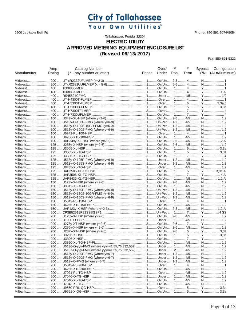
2600 Jackson Bluff Rd. Phone: 850-891-5074/5054
Tallahassee, Florida 32304 ELECTRIC UTILITY
APPROVED METERING EQUIPMENT ENCLOSURE LIST (Revised 06/13/2017)
Fax: 850-891-5322
Amp Catalog Number Over/ # # Bypass Configuration Manufacturer Rating ( * - any number or letter) Phase Under Pos. Term Y/N (AL=Aluminum)
Page 9 of 13
Midwest ......................... 200 ...... UT-xR2332UFLMEP (x=2-3) ............................................ 1 ......... Ov/Un ......2-3 ......... 4 ............ N ..................... 1 Midwest ......................... 200 ...... UTxR2392UUFLMEP (x = 5-6) ......................................... 1 ......... Ov/Un ......5-6 ......... 4 ............ N ..................... 1 Midwest ......................... 400 ...... 1008836-MEP .................................................................. 1 ......... Ov/Un ....... 1 ........... 4 ............ Y ..................... 1 Midwest ......................... 400 ...... 1008837-MEP .................................................................. 1 ......... Ov/Un ....... 1 ........... 4 ............ Y ................. 1 Al Midwest ......................... 400 ...... RS45524CFMG ............................................................... 1 ......... Under ....... 1 ......... 4/5 ........... Y .................. 1/2 Midwest ......................... 400 ...... UT-H4300T-FLMEP ......................................................... 1 .......... Over ........ 1 ........... 4 ............ Y ..................... 1 Midwest ......................... 400 ...... UT-H5300T-FLMEP ......................................................... 1 .......... Over ........ 1 ........... 5 ............ Y .............. 3,3a,b Midwest ......................... 400 ...... UT-H5330U-FLMEP ......................................................... 1 ......... Ov/Un ....... 1 ........... 5 ............ Y ................ 3,3a Midwest ......................... 400 ...... UT-H7300TFLMEP .......................................................... 3 .......... Over ........ 1 ........... 7 ............ Y ..................... 4 Midwest ......................... 400 ...... UT-H7330UFLMEP .......................................................... 3 ......... Ov/Un ....... 1 ........... 7 ............ Y ..................... 4 Milbank .......................... 100 ...... U349y-XL-HSP (where y=2-6) .......................................... 1 ......... Ov/Un ......2-6 ....... 4/5 ........... N .................. 1,2 Milbank .......................... 100 ...... U513y-O-100P-FMG (where y=6-9) ................................. 1 ........ Un-Ped ....1-2 ....... 4/5 ........... N .................. 1,2 Milbank .......................... 100 ...... U513y-O-100S-10GR-FMG (y=6-9).................................. 1 ........ Un-Ped .....1-2 ....... 4/5 ........... N .................. 1,2 Milbank .......................... 100 ...... U513y-O-100S-FMG (where y=6-9) ................................. 1 ........ Un-Ped .....1-2 ....... 4/5 ........... N .................. 1,2 Milbank .......................... 100 ...... U5842-RL-100-HSP ......................................................... 1 .......... Over ........ 1 ........... 4 ............ N ..................... 1 Milbank .......................... 100 ...... U6266-XTL-100-HSP ....................................................... 1 ......... Ov/Un ....... 1 ......... 4/5 ........... N .................. 1,2 Milbank .......................... 100 ...... UAP349y-XL-HSP (where y=2-6) ..................................... 1 ......... Ov/Un ......2-6 ....... 4/5 ........... N .............. 1,2 Al Milbank .......................... 125 ...... U285y-X-HSP (where y=2-6) ............................................ 1 ......... Ov/Un ......2-6 ....... 4/5 ........... N .................. 1,2 Milbank .......................... 125 ...... U3505-XL-HSP ................................................................ 1 ......... Ov/Un ....... 1 ........... 5 ............ Y ................ 3,3a Milbank .......................... 125 ...... U3505-XL-TG-HSP .......................................................... 1 ......... Ov/Un ....... 1 ........... 5 ............ Y ................ 3,3a Milbank .......................... 125 ...... U3506-XL-TG-HSP .......................................................... 3 ......... Ov/Un ....... 1 ........... 7 ............ Y ..................... 4 Milbank .......................... 125 ...... U513y-O-125P-FMG (where y=6-9) ................................. 1 ......... Under ......1-2 ....... 4/5 ........... N .................. 1,2 Milbank .......................... 125 ...... U513y-O-125S-FMG (where y=6-9) ................................. 1 ......... Under ......1-2 ....... 4/5 ........... N .................. 1,2 Milbank .......................... 125 ...... U8435-XL-TG-HSP .......................................................... 1 .......... Over ........ 1 ......... 4/5 ........... N .................. 1,2 Milbank .......................... 125 ...... UAP3505-XL-TG-HSP...................................................... 1 ......... Ov/Un ....... 1 ........... 5 ............ Y ............ 3,3a Al Milbank .......................... 125 ...... UAP3506-XL-TG-HSP...................................................... 3 ......... Ov/Un ....... 1 ........... 7 ............ Y ................. 4 Al Milbank .......................... 125 ...... UAP8435-XL-TG-HSP...................................................... 1 ......... Ov/Un ....... 1 ......... 4/5 ........... N .............. 1,2 Al Milbank .......................... 150 ...... U123y-X-HSP (where y=2-6) ............................................ 1 ......... Ov/Un ......2-6 ....... 4/5 ........... N .................. 1,2 Milbank .......................... 150 ...... U3312-XL-TG-HSP .......................................................... 1 ......... Ov/Un ....... 1 ......... 4/5 ........... N .................. 1,2 Milbank .......................... 150 ...... U513y-O-150P-FMG (where y=6-9) ................................. 1 ........ Un-Ped .....1-2 ....... 4/5 ........... N .................. 1,2 Milbank .......................... 150 ...... U513y-O-150S-10GR-FMG (y=6-9).................................. 1 ........ Un-Ped .....1-2 ....... 4/5 ........... N .................. 1,2 Milbank .......................... 150 ...... U513y-O-150S-FMG (where y=6-9) ................................. 1 ........ Un-Ped .....1-2 ....... 4/5 ........... N .................. 1,2 Milbank .......................... 150 ...... U5842-RL-150-HSP ......................................................... 1 .......... Over ........ 1 ........... 4 ............ N ..................... 1 Milbank .......................... 150 ...... U6266-XTL-150-HSP ....................................................... 1 ......... Ov/Un ....... 1 ......... 4/5 ........... N .................. 1,2 Milbank .......................... 150 ...... UAP123y-X-HSP (where y=2-3) ....................................... 1 ......... Ov/Un ......2-3 ....... 4/5 ........... N .............. 1,2 Al Milbank .......................... 200 ...... CP3B52519R22SSSGSP1 ............................................... 3 ........ Un-Ped ...... 1 ........... 7 ............ Y ................ 4 SS Milbank .......................... 200 ...... U125y-X-HSP (where y=2-6) ............................................ 1 ......... Ov/Un ......2-6 ....... 4/5 ........... Y .................. 1,2 Milbank .......................... 200 ...... U1980-O-HSP .................................................................. 1 ......... Under ....... 1 ......... 4/5 ........... N .................. 1,2 Milbank .......................... 200 ...... U273y-XT-HSP (where y=2-6).......................................... 3 ......... Ov/Un ......2-6 ......... 7 ............ Y ..................... 4 Milbank .......................... 200 ...... U286y-X-HSP (where y=2-6) ............................................ 1 ......... Ov/Un ......2-6 ....... 4/5 ........... N .................. 1,2 Milbank .......................... 200 ...... U287y-XT-HSP (where y=2-6).......................................... 1 ......... Ov/Un ......2-6 ......... 5 ............ Y ................ 3,3a Milbank .......................... 200 ...... U3296-X-HSP .................................................................. 1 ......... Ov/Un ....... 1 ........... 5 ............ Y ................ 3,3a Milbank .......................... 200 ...... U3306-X-HSP .................................................................. 3 ......... Ov/Un ....... 1 ........... 7 ............ Y ..................... 4 Milbank .......................... 200 ...... U3850-XL-TG-HSP-PL ..................................................... 1 ......... Ov/Un ....... 1 ......... 4/5 ........... N .................. 1,2 Milbank .......................... 200 ...... U5136-O-yyy-FMG (where yyy=41,55,75,332,552) .......... 1 ......... Under ....... 1 ......... 4/5 ........... N .................. 1,2 Milbank .......................... 200 ...... U5137-O-yyy-FMG (where yyy=41,55,75,332,552) .......... 1 ......... Under ....... 2 ......... 4/5 ........... N .................. 1,2 Milbank .......................... 200 ...... U513y-O-200P-FMG (where y=6-7) ................................. 1 ......... Under ......1-2 ....... 4/5 ........... N .................. 1,2 Milbank .......................... 200 ...... U513y-O-200S-FMG (where y=6-7) ................................. 1 ......... Under ......1-2 ....... 4/5 ........... N .................. 1,2 Milbank .......................... 200 ...... U513y-O-FMG (where y=6-7) ........................................... 1 ......... Under ......1-2 ....... 4/5 ........... N .................. 1,2 Milbank .......................... 200 ...... U5842-RL-200-HSP ......................................................... 1 .......... Over ........ 1 ........... 4 ............ N ..................... 1 Milbank .......................... 200 ...... U6266-XTL-200-HSP ....................................................... 1 ......... Ov/Un ....... 1 ......... 4/5 ........... N .................. 1,2 Milbank .......................... 200 ...... U7021-RL-TG-HSP .......................................................... 1 .......... Over ........ 1 ......... 4/5 ........... N .................. 1,2 Milbank .......................... 200 ...... U7040-O-TG-HSP ............................................................ 1 ......... Under ....... 1 ......... 4/5 ........... N .................. 1,2 Milbank .......................... 200 ...... U7040-XL-TG-HSP .......................................................... 1 ......... Ov/Un ....... 1 ......... 4/5 ........... N .................. 1,2 Milbank .......................... 200 ...... U7043-XL-TG ................................................................... 1 ......... Ov/Un ....... 1 ......... 4/5 ........... N .................. 1,2 Milbank .......................... 200 ...... U9550-RRL-QG-HSP ....................................................... 1 .......... Over ........ 1 ........... 5 ............ Y ................ 3,3a Milbank .......................... 200 ...... U9551-X-QG-HSP ............................................................ 1 ......... Ov/Un ....... 1 ........... 5 ............ Y ................ 3,3a
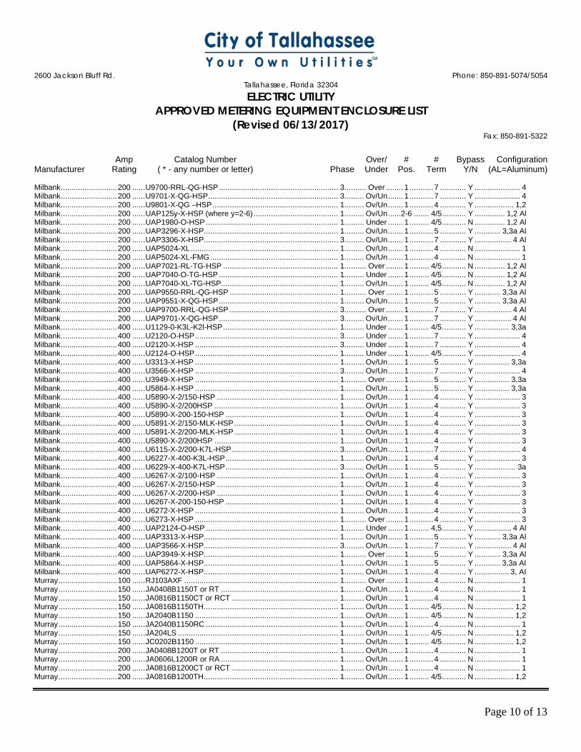
2600 Jackson Bluff Rd. Phone: 850-891-5074/5054
Tallahassee, Florida 32304 ELECTRIC UTILITY
APPROVED METERING EQUIPMENT ENCLOSURE LIST (Revised 06/13/2017)
Fax: 850-891-5322
Amp Catalog Number Over/ # # Bypass Configuration Manufacturer Rating ( * - any number or letter) Phase Under Pos. Term Y/N (AL=Aluminum)
Page 10 of 13
Milbank .......................... 200 ...... U9700-RRL-QG-HSP ....................................................... 3 .......... Over ........ 1 ........... 7 ............ Y ..................... 4 Milbank .......................... 200 ...... U9701-X-QG-HSP ............................................................ 3 ......... Ov/Un ....... 1 ........... 7 ............ Y ..................... 4 Milbank .......................... 200 ...... U9801-X-QG –HSP .......................................................... 1 ......... Ov/Un ....... 1 ........... 4 ............ Y .................. 1,2 Milbank .......................... 200 ...... UAP125y-X-HSP (where y=2-6) ....................................... 1 ......... Ov/Un ......2-6 ....... 4/5 ........... Y .............. 1,2 Al Milbank .......................... 200 ...... UAP1980-O-HSP ............................................................. 1 ......... Under ....... 1 ......... 4/5 ........... N .............. 1,2 Al Milbank .......................... 200 ...... UAP3296-X-HSP.............................................................. 1 ......... Ov/Un ....... 1 ........... 5 ............ Y ............ 3,3a Al Milbank .......................... 200 ...... UAP3306-X-HSP.............................................................. 3 ......... Ov/Un ....... 1 ........... 7 ............ Y ................. 4 Al Milbank .......................... 200 ...... UAP5024-XL .................................................................... 1 ......... Ov/Un ....... 1 ........... 4 ............ N ..................... 1 Milbank .......................... 200 ...... UAP5024-XL-FMG ........................................................... 1 ......... Ov/Un ....... 1 ........... 4 ............ N ..................... 1 Milbank .......................... 200 ...... UAP7021-RL-TG-HSP ..................................................... 1 .......... Over ........ 1 ......... 4/5 ........... N .............. 1,2 Al Milbank .......................... 200 ...... UAP7040-O-TG-HSP ....................................................... 1 ......... Under ....... 1 ......... 4/5 ........... N .............. 1,2 Al Milbank .......................... 200 ...... UAP7040-XL-TG-HSP...................................................... 1 ......... Ov/Un ....... 1 ......... 4/5 ........... N .............. 1,2 Al Milbank .......................... 200 ...... UAP9550-RRL-QG-HSP .................................................. 1 .......... Over ........ 1 ........... 5 ............ Y ............ 3,3a Al Milbank .......................... 200 ...... UAP9551-X-QG-HSP ....................................................... 1 ......... Ov/Un ....... 1 ........... 5 ............ Y ............ 3,3a Al Milbank .......................... 200 ...... UAP9700-RRL-QG-HSP .................................................. 3 .......... Over ........ 1 ........... 7 ............ Y ................. 4 Al Milbank .......................... 200 ...... UAP9701-X-QG-HSP ....................................................... 3 ......... Ov/Un ....... 1 ........... 7 ............ Y ................. 4 Al Milbank .......................... 400 ...... U1129-0-K3L-K2l-HSP ..................................................... 1 ......... Under ....... 1 ......... 4/5 ........... Y ................ 3,3a Milbank .......................... 400 ...... U2120-O-HSP .................................................................. 3 ......... Under ....... 1 ........... 7 ............ Y ..................... 4 Milbank .......................... 400 ...... U2120-X-HSP .................................................................. 3 ......... Under ....... 1 ........... 7 ............ Y ..................... 4 Milbank .......................... 400 ...... U2124-O-HSP .................................................................. 1 ......... Under ....... 1 ......... 4/5 ........... Y ..................... 4 Milbank .......................... 400 ...... U3313-X-HSP .................................................................. 1 ......... Ov/Un ....... 1 ........... 5 ............ Y ................ 3,3a Milbank .......................... 400 ...... U3566-X-HSP .................................................................. 3 ......... Ov/Un ....... 1 ........... 7 ............ Y ..................... 4 Milbank .......................... 400 ...... U3949-X-HSP .................................................................. 1 .......... Over ........ 1 ........... 5 ............ Y ................ 3,3a Milbank .......................... 400 ...... U5864-X-HSP .................................................................. 1 ......... Ov/Un ....... 1 ........... 5 ............ Y ................ 3,3a Milbank .......................... 400 ...... U5890-X-2/150-HSP ........................................................ 1 ......... Ov/Un ....... 1 ........... 4 ............ Y ..................... 3 Milbank .......................... 400 ...... U5890-X-2/200HSP ......................................................... 1 ......... Ov/Un ....... 1 ........... 4 ............ Y ..................... 3 Milbank .......................... 400 ...... U5890-X-200-150-HSP .................................................... 1 ......... Ov/Un ....... 1 ........... 4 ............ Y ..................... 3 Milbank .......................... 400 ...... U5891-X-2/150-MLK-HSP ................................................ 1 ......... Ov/Un ....... 1 ........... 4 ............ Y ..................... 3 Milbank .......................... 400 ...... U5891-X-2/200-MLK-HSP ................................................ 1 ......... Ov/Un ....... 1 ........... 4 ............ Y ..................... 3 Milbank .......................... 400 ...... U5890-X-2/200HSP ......................................................... 1 ......... Ov/Un ....... 1 ........... 4 ............ Y ..................... 3 Milbank .......................... 400 ...... U6115-X-2/200-K7L-HSP ................................................. 3 ......... Ov/Un ....... 1 ........... 7 ............ Y ..................... 4 Milbank .......................... 400 ...... U6227-X-400-K3L-HSP .................................................... 1 ......... Ov/Un ....... 1 ........... 4 ............ Y ..................... 3 Milbank .......................... 400 ...... U6229-X-400-K7L-HSP .................................................... 3 ......... Ov/Un ....... 1 ........... 5 ............ Y ................... 3a Milbank .......................... 400 ...... U6267-X-2/100-HSP ........................................................ 1 ......... Ov/Un ....... 1 ........... 4 ............ Y ..................... 3 Milbank .......................... 400 ...... U6267-X-2/150-HSP ........................................................ 1 ......... Ov/Un ....... 1 ........... 4 ............ Y ..................... 3 Milbank .......................... 400 ...... U6267-X-2/200-HSP ........................................................ 1 ......... Ov/Un ....... 1 ........... 4 ............ Y ..................... 3 Milbank .......................... 400 ...... U6267-X-200-150-HSP .................................................... 1 ......... Ov/Un ....... 1 ........... 4 ............ Y ..................... 3 Milbank .......................... 400 ...... U6272-X-HSP .................................................................. 1 ......... Ov/Un ....... 1 ........... 4 ............ Y ..................... 3 Milbank .......................... 400 ...... U6273-X-HSP .................................................................. 1 .......... Over ........ 1 ........... 4 ............ Y ..................... 3 Milbank .......................... 400 ...... UAP2124-O-HSP ............................................................. 1 ......... Under ....... 1 ......... 4,5 ........... Y ................. 4 Al Milbank .......................... 400 ...... UAP3313-X-HSP.............................................................. 1 ......... Ov/Un ....... 1 ........... 5 ............ Y ............ 3,3a Al Milbank .......................... 400 ...... UAP3566-X-HSP.............................................................. 3 ......... Ov/Un ....... 1 ........... 7 ............ Y ................. 4 Al Milbank .......................... 400 ...... UAP3949-X-HSP.............................................................. 1 .......... Over ........ 1 ........... 5 ............ Y ............ 3,3a Al Milbank .......................... 400 ...... UAP5864-X-HSP.............................................................. 1 ......... Ov/Un ....... 1 ........... 5 ............ Y ............ 3,3a AI Milbank .......................... 400 ...... UAP6272-X-HSP.............................................................. 1 ......... Ov/Un ....... 1 ........... 4 ............ Y ................ 3, AI Murray ........................... 100 ...... RJ103AXF ....................................................................... 1 .......... Over ........ 1 ........... 4 ............ N ..................... 1 Murray ........................... 150 ...... JA0408B1150T or RT ...................................................... 1 ......... Ov/Un ....... 1 ........... 4 ............ N ..................... 1 Murray ........................... 150 ...... JA0816B1150CT or RCT ................................................. 1 ......... Ov/Un ....... 1 ........... 4 ............ N ..................... 1 Murray ........................... 150 ...... JA0816B1150TH .............................................................. 1 ......... Ov/Un ....... 1 ......... 4/5 ........... N .................. 1,2 Murray ........................... 150 ...... JA2040B1150 .................................................................. 1 ......... Ov/Un ....... 1 ......... 4/5 ........... N .................. 1,2 Murray ........................... 150 ...... JA2040B1150RC ............................................................. 1 ......... Ov/Un ....... 1 ........... 4 ............ N ..................... 1 Murray ........................... 150 ...... JA204LS .......................................................................... 1 ......... Ov/Un ....... 1 ......... 4/5 ........... N .................. 1,2 Murray ........................... 150 ...... JC0202B1150 .................................................................. 1 ......... Ov/Un ....... 1 ......... 4/5 ........... N .................. 1,2 Murray ........................... 200 ...... JA0408B1200T or RT ...................................................... 1 ......... Ov/Un ....... 1 ........... 4 ............ N ..................... 1 Murray ........................... 200 ...... JA0606L1200R or RA ...................................................... 1 ......... Ov/Un ....... 1 ........... 4 ............ N ..................... 1 Murray ........................... 200 ...... JA0816B1200CT or RCT ................................................. 1 ......... Ov/Un ....... 1 ........... 4 ............ N ..................... 1 Murray ........................... 200 ...... JA0816B1200TH .............................................................. 1 ......... Ov/Un ....... 1 ......... 4/5 ........... N .................. 1,2
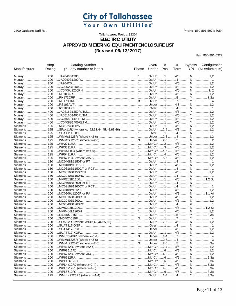
2600 Jackson Bluff Rd. Phone: 850-891-5074/5054
Tallahassee, Florida 32304 ELECTRIC UTILITY
APPROVED METERING EQUIPMENT ENCLOSURE LIST (Revised 06/13/2017)
Fax: 850-891-5322
Amp Catalog Number Over/ # # Bypass Configuration Manufacturer Rating ( * - any number or letter) Phase Under Pos. Term Y/N (AL=Aluminum)
Page 11 of 13
Murray ........................... 200 ...... JA2040B1200 .................................................................. 1 ......... Ov/Un ....... 1 ......... 4/5 ........... N .................. 1,2 Murray ........................... 200 ...... JA2040B1200RC ............................................................. 1 ......... Ov/Un ....... 1 ........... 4 ............ N ..................... 1 Murray ........................... 200 ...... JA204TS .......................................................................... 1 ......... Ov/Un ....... 1 ......... 4/5 ........... N .................. 1,2 Murray ........................... 200 ...... JC0202B1200 .................................................................. 1 ......... Ov/Un ....... 1 ......... 4/5 ........... N .................. 1,2 Murray ........................... 200 ...... JC0406L1200RH.............................................................. 1 ......... Ov/Un ....... 1 ......... 4/5 ........... N ................. 1, 2 Murray ........................... 200 ...... RB103AR ......................................................................... 1 ......... Ov/Un ....... 1 ......... 4/5 ........... N .................. 1,2 Murray ........................... 200 ...... RH173CRF ...................................................................... 1 ......... Ov/Un ....... 1 ........... 5 ............ Y ................ 3,3a Murray ........................... 200 ...... RH173GRF ...................................................................... 3 ......... Ov/Un ....... 1 ........... 7 ............ Y ..................... 4 Murray ........................... 200 ...... RS103AVF ....................................................................... 1 ......... Under ....... 1 ......... 4,5 ........... N .................. 1,2 Murray ........................... 200 ...... RS103AXF ....................................................................... 1 .......... Over ........ 1 ........... 4 ............ N ..................... 1 Murray ........................... 400 ...... JA0816B1350RLTM ......................................................... 1 ......... Ov/Un ....... 1 ......... 4/5 ........... Y .................. 1,2 Murray ........................... 400 ...... JA0816B1400RLTM ......................................................... 1 ......... Ov/Un ....... 1 ......... 4/5 ........... Y .................. 1,2 Murray ........................... 400 ...... JC0404L1400RLM ........................................................... 1 ......... Ov/Un ....... 1 ......... 4/5 ........... Y .................. 1,2 Murray ........................... 400 ...... JC0408B1400RLTM ......................................................... 1 ......... Ov/Un ....... 1 ......... 4/5 ........... Y .................. 1,2 Siemens ........................ 125 ...... MC1224B1125 ................................................................. 1 ......... Ov/Un ....... 1 ......... 4/5 ........... N .................. 1,2 Siemens ........................ 125 ...... SPxx11RJ (where xx=22,33,44,45,46,65,66) ................... 1 ......... Ov/Un ......2-6 ....... 4/5 ........... N .................. 1,2 Siemens ........................ 125 ...... SUAT111-OGF ................................................................ 1 .......... Over ........ 1 ........... 4 ............ N ..................... 1 Siemens ........................ 125 ...... WMMx1125R (where x=2-6) ............................................ 1 ......... Under ......2-6 ......... 4 ............ N .................. 1,2 Siemens ........................ 125 ...... WMMx2125RJ (where x=2-6) ........................................... 3 ......... Under ......2-6 ......... 5 ............ N ..................... 2 Siemens ........................ 125 ...... WP2211RJ ....................................................................... 1 ......... Mtr Ctr ...... 2 ......... 4/5 ........... N .................. 1,2 Siemens ........................ 125 ...... WP3311RJ ....................................................................... 1 ......... Mtr Ctr ...... 3 ......... 4/5 ........... N .................. 1,2 Siemens ........................ 125 ...... WP4X11RJ (where x=4-6) ................................................ 1 ......... Mtr Ctr .....4-6 ....... 4/5 ........... N .................. 1,2 Siemens ........................ 125 ...... WP5411RJ ....................................................................... 1 ......... Mtr Ctr ...... 4 ......... 4/5 ........... N .................. 1,2 Siemens ........................ 125 ...... WP6x11RJ (where x=5-6) ................................................ 1 ......... Mtr Ctr .....5-6 ....... 4/5 ........... N .................. 1,2 Siemens ........................ 150 ...... MC0408B1150T or RT ..................................................... 1 ......... Ov/Un ....... 1 ........... 4 ............ N ..................... 1 Siemens ........................ 150 ...... MC0408MB1150T ............................................................ 1 ......... Ov/Un ....... 1 ......... 4/5 ........... N .................. 1,2 Siemens ........................ 150 ...... MC0816B1150CT or RCT ................................................ 1 ......... Ov/Un ....... 1 ........... 4 ............ N ..................... 1 Siemens ........................ 150 ...... MC0816B1150RTH .......................................................... 1 ......... Ov/Un ....... 1 ......... 4/5 ........... N .................. 1,2 Siemens ........................ 150 ...... MC2040B1150RC ............................................................ 1 ......... Ov/Un ....... 1 ........... 4 ............ N ..................... 1 Siemens ........................ 150 ...... MM0202B1150 ................................................................. 1 ......... Ov/Un ....... 1 ......... 4/5 ........... N .............. 1,2 St Siemens ........................ 200 ...... MC0408B1200T or RT ..................................................... 1 ......... Ov/Un ....... 1 ........... 4 ............ N ..................... 1 Siemens ........................ 200 ...... MC0816B1200CT or RCT ................................................ 1 ......... Ov/Un ....... 1 ........... 4 ............ N ..................... 1 Siemens ........................ 200 ...... MC0408MB1200T ............................................................ 1 ......... Ov/Un ....... 1 ......... 4/5 ........... N .................. 1,2 Siemens ........................ 200 ...... MC0606L1200R or RA ..................................................... 1 ......... Ov/Un ....... 1 ......... 4/5 ........... N .............. 1,1 AI Siemens ........................ 200 ...... MC0816B1200RTH .......................................................... 1 ......... Ov/Un ....... 1 ......... 4/5 ........... N .................. 1,2 Siemens ........................ 200 ...... MC2040B1200 ................................................................. 1 ......... Ov/Un ....... 1 ......... 4/5 ........... N .................. 1,2 Siemens ........................ 200 ...... MC2040B1200RC ............................................................ 1 ......... Ov/Un ....... 1 ........... 4 ............. n ..................... 1 Siemens ........................ 200 ...... MM0202B1200 ................................................................. 1 ......... Ov/Un ....... 1 ......... 4/5 ........... N .............. 1,2 St Siemens ........................ 200 ...... MM0406L1200H .............................................................. 1 ......... Ov/Un ....... 1 ......... 4/5 ........... N .................. 1,2 Siemens ........................ 200 ...... S40405-015F ................................................................... 1 ......... Ov/Un ....... 1 ........... 5 ............ Y ................ 3,3a Siemens ........................ 200 ...... S40407-015F ................................................................... 3 ......... Ov/Un ....... 1 ........... 7 ............ Y ..................... 4 Siemens ........................ 200 ...... SPxx12RJ (where xx=42,43,44,65,66) ............................. 1 ......... Ov/Un ......2-6 ....... 4/5 ........... N .................. 1,2 Siemens ........................ 200 ...... SUAT317-OGF ................................................................ 1 .......... Over ........ 1 ........... 4 ............ N ..................... 1 Siemens ........................ 200 ...... SUAT417-PGF ................................................................. 1 ......... Under ....... 1 ......... 4/5 ........... N .................. 1,2 Siemens ........................ 200 ...... SUAT417-XGF ................................................................. 1 ......... Ov/Un ....... 1 ......... 4/5 ........... N .................. 1,2 Siemens ........................ 200 ...... WMLx3200RJ (where x=1-4) ............................................ 3 ......... Under ......1-4 ......... 7 ............ Y ..................... 4 Siemens ........................ 200 ...... WMMx1225R (where x=2-6) ............................................ 1 ......... Under ...... 2,6.......... 4 ............ N ..................... 3 Siemens ........................ 200 ...... WMMx2225RJ (where x=2-6) ........................................... 3 ......... Under ......2-6 ......... 5 ............ N ................... 3a Siemens ........................ 200 ...... WP4x12RJ (where x=2-4) ................................................ 1 ......... Mtr Ctr .....2-4 ....... 4/5 ........... N .................. 1,2 Siemens ........................ 200 ...... WP68612RJ ..................................................................... 1 ......... Mtr Ctr ...... 6 ......... 4/5 ........... N .................. 1,2 Siemens ........................ 200 ...... WP6x12RJ (where x=4-6) ................................................ 1 ......... Mtr Ctr .....4-6 ....... 4/5 ........... N .................. 1,2 Siemens ........................ 200 ...... WP8612RJ ....................................................................... 1 ......... Mtr Ctr ...... 6 ......... 4/5 ........... N ................ 3,3a Siemens ........................ 200 ...... WPL10612RJ ................................................................... 1 ......... Mtr Ctr ...... 6 ......... 4/5 ........... N ................ 3,3a Siemens ........................ 200 ...... WPL4x12RJ (where x=2-4) .............................................. 1 ......... Mtr Ctr .....2-4 ....... 4/5 ........... N ................ 3,3a Siemens ........................ 200 ...... WPL6x12RJ (where x=4-6) .............................................. 1 ......... Mtr Ctr .....4-6 ....... 4/5 ........... N ................ 3,3a Siemens ........................ 200 ...... WPL8612RJ ..................................................................... 1 ......... Mtr Ctr ...... 6 ......... 4/5 ........... N ................ 3,3a Siemens ........................ 225 ...... WML1x2225RJ (where x=1-4) .......................................... 1 ......... Ov/Un ......1-4 ......... 4 ............ Y ................ 3,3a
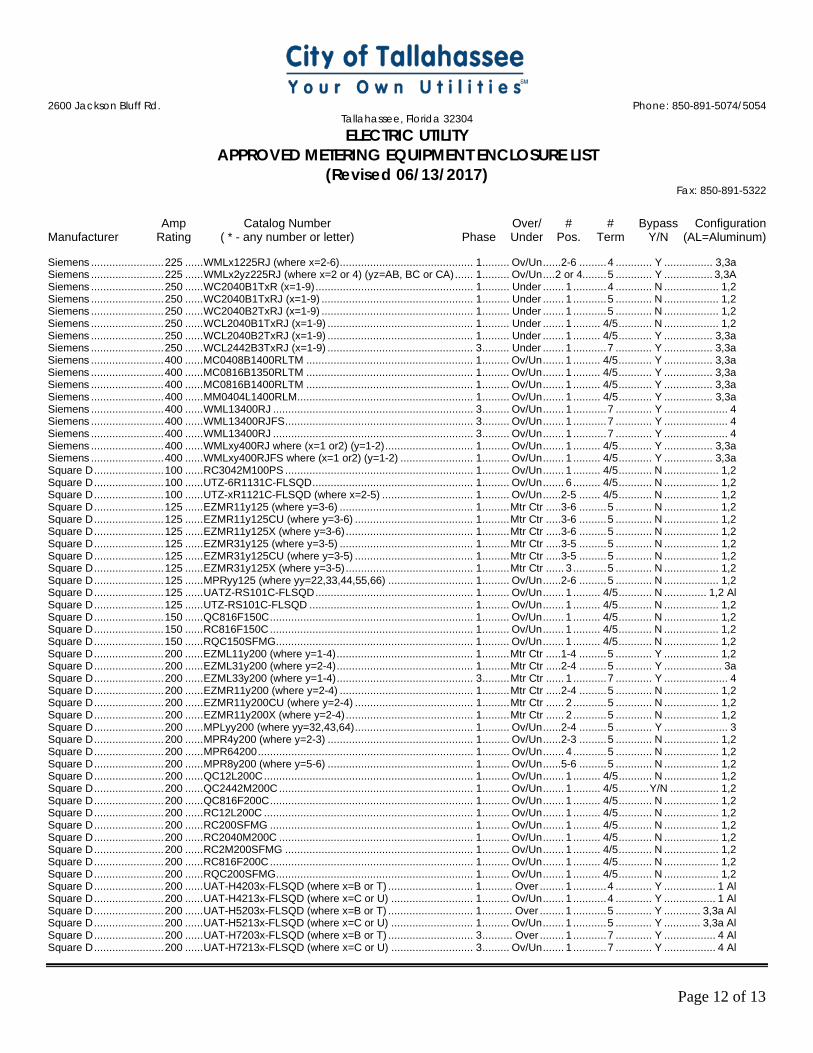
2600 Jackson Bluff Rd. Phone: 850-891-5074/5054
Tallahassee, Florida 32304 ELECTRIC UTILITY
APPROVED METERING EQUIPMENT ENCLOSURE LIST (Revised 06/13/2017)
Fax: 850-891-5322
Amp Catalog Number Over/ # # Bypass Configuration Manufacturer Rating ( * - any number or letter) Phase Under Pos. Term Y/N (AL=Aluminum)
Page 12 of 13
Siemens ........................ 225 ...... WMLx1225RJ (where x=2-6) ............................................ 1 ......... Ov/Un ......2-6 ......... 4 ............ Y ................ 3,3a Siemens ........................ 225 ...... WMLx2yz225RJ (where x=2 or 4) (yz=AB, BC or CA) ...... 1 ......... Ov/Un .... 2 or 4........ 5 ............ Y ................ 3,3A Siemens ........................ 250 ...... WC2040B1TxR (x=1-9) .................................................... 1 ......... Under ....... 1 ........... 4 ............ N .................. 1,2 Siemens ........................ 250 ...... WC2040B1TxRJ (x=1-9) .................................................. 1 ......... Under ....... 1 ........... 5 ............ N .................. 1,2 Siemens ........................ 250 ...... WC2040B2TxRJ (x=1-9) .................................................. 1 ......... Under ....... 1 ........... 5 ............ N .................. 1,2 Siemens ........................ 250 ...... WCL2040B1TxRJ (x=1-9) ................................................ 1 ......... Under ....... 1 ......... 4/5 ........... N .................. 1,2 Siemens ........................ 250 ...... WCL2040B2TxRJ (x=1-9) ................................................ 1 ......... Under ....... 1 ......... 4/5 ........... Y ................ 3,3a Siemens ........................ 250 ...... WCL2442B3TxRJ (x=1-9) ................................................ 3 ......... Under ....... 1 ........... 7 ............ Y ................ 3,3a Siemens ........................ 400 ...... MC0408B1400RLTM ....................................................... 1 ......... Ov/Un ....... 1 ......... 4/5 ........... Y ................ 3,3a Siemens ........................ 400 ...... MC0816B1350RLTM ....................................................... 1 ......... Ov/Un ....... 1 ......... 4/5 ........... Y ................ 3,3a Siemens ........................ 400 ...... MC0816B1400RLTM ....................................................... 1 ......... Ov/Un ....... 1 ......... 4/5 ........... Y ................ 3,3a Siemens ........................ 400 ...... MM0404L1400RLM .......................................................... 1 ......... Ov/Un ....... 1 ......... 4/5 ........... Y ................ 3,3a Siemens ........................ 400 ...... WML13400RJ .................................................................. 3 ......... Ov/Un ....... 1 ........... 7 ............ Y ..................... 4 Siemens ........................ 400 ...... WML13400RJFS .............................................................. 3 ......... Ov/Un ....... 1 ........... 7 ............ Y ..................... 4 Siemens ........................ 400 ...... WML13400RJ .................................................................. 3 ......... Ov/Un ....... 1 ........... 7 ............ Y ..................... 4 Siemens ........................ 400 ...... WMLxy400RJ where (x=1 or2) (y=1-2) ............................. 1 ......... Ov/Un ....... 1 ......... 4/5 ........... Y ................ 3,3a Siemens ........................ 400 ...... WMLxy400RJFS where (x=1 or2) (y=1-2) ........................ 1 ......... Ov/Un ....... 1 ......... 4/5 ........... Y ................ 3,3a Square D ....................... 100 ...... RC3042M100PS .............................................................. 1 ......... Ov/Un ....... 1 ......... 4/5 ........... N .................. 1,2 Square D ....................... 100 ...... UTZ-6R1131C-FLSQD ..................................................... 1 ......... Ov/Un ....... 6 ......... 4/5 ........... N .................. 1,2 Square D ....................... 100 ...... UTZ-xR1121C-FLSQD (where x=2-5) .............................. 1 ......... Ov/Un ......2-5 ....... 4/5 ........... N .................. 1,2 Square D ....................... 125 ...... EZMR11y125 (where y=3-6) ............................................ 1 ......... Mtr Ctr .....3-6 ......... 5 ............ N .................. 1,2 Square D ....................... 125 ...... EZMR11y125CU (where y=3-6) ....................................... 1 ......... Mtr Ctr .....3-6 ......... 5 ............ N .................. 1,2 Square D ....................... 125 ...... EZMR11y125X (where y=3-6) .......................................... 1 ......... Mtr Ctr .....3-6 ......... 5 ............ N .................. 1,2 Square D ....................... 125 ...... EZMR31y125 (where y=3-5) ............................................ 1 ......... Mtr Ctr .....3-5 ......... 5 ............ N .................. 1,2 Square D ....................... 125 ...... EZMR31y125CU (where y=3-5) ....................................... 1 ......... Mtr Ctr .....3-5 ......... 5 ............ N .................. 1,2 Square D ....................... 125 ...... EZMR31y125X (where y=3-5) .......................................... 1 ......... Mtr Ctr ...... 3 ........... 5 ............ N .................. 1,2 Square D ....................... 125 ...... MPRyy125 (where yy=22,33,44,55,66) ............................ 1 ......... Ov/Un ......2-6 ......... 5 ............ N .................. 1,2 Square D ....................... 125 ...... UATZ-RS101C-FLSQD .................................................... 1 ......... Ov/Un ....... 1 ......... 4/5 ........... N .............. 1,2 Al Square D ....................... 125 ...... UTZ-RS101C-FLSQD ...................................................... 1 ......... Ov/Un ....... 1 ......... 4/5 ........... N .................. 1,2 Square D ....................... 150 ...... QC816F150C ................................................................... 1 ......... Ov/Un ....... 1 ......... 4/5 ........... N .................. 1,2 Square D ....................... 150 ...... RC816F150C ................................................................... 1 ......... Ov/Un ....... 1 ......... 4/5 ........... N .................. 1,2 Square D ....................... 150 ...... RQC150SFMG ................................................................. 1 ......... Ov/Un ....... 1 ......... 4/5 ........... N .................. 1,2 Square D ....................... 200 ...... EZML11y200 (where y=1-4) ............................................. 1 ......... Mtr Ctr .....1-4 ......... 5 ............ Y .................. 1,2 Square D ....................... 200 ...... EZML31y200 (where y=2-4) ............................................. 1 ......... Mtr Ctr .....2-4 ......... 5 ............ Y ................... 3a Square D ....................... 200 ...... EZML33y200 (where y=1-4) ............................................. 3 ......... Mtr Ctr ...... 1 ........... 7 ............ Y ..................... 4 Square D ....................... 200 ...... EZMR11y200 (where y=2-4) ............................................ 1 ......... Mtr Ctr .....2-4 ......... 5 ............ N .................. 1,2 Square D ....................... 200 ...... EZMR11y200CU (where y=2-4) ....................................... 1 ......... Mtr Ctr ...... 2 ........... 5 ............ N .................. 1,2 Square D ....................... 200 ...... EZMR11y200X (where y=2-4) .......................................... 1 ......... Mtr Ctr ...... 2 ........... 5 ............ N .................. 1,2 Square D ....................... 200 ...... MPLyy200 (where yy=32,43,64) ....................................... 1 ......... Ov/Un ......2-4 ......... 5 ............ Y ..................... 3 Square D ....................... 200 ...... MPR4y200 (where y=2-3) ................................................ 1 ......... Ov/Un ......2-3 ......... 5 ............ N .................. 1,2 Square D ....................... 200 ...... MPR64200 ....................................................................... 1 ......... Ov/Un ....... 4 ........... 5 ............ N .................. 1,2 Square D ....................... 200 ...... MPR8y200 (where y=5-6) ................................................ 1 ......... Ov/Un ......5-6 ......... 5 ............ N .................. 1,2 Square D ....................... 200 ...... QC12L200C ..................................................................... 1 ......... Ov/Un ....... 1 ......... 4/5 ........... N .................. 1,2 Square D ....................... 200 ...... QC2442M200C ................................................................ 1 ......... Ov/Un ....... 1 ......... 4/5 .......... Y/N ................ 1,2 Square D ....................... 200 ...... QC816F200C ................................................................... 1 ......... Ov/Un ....... 1 ......... 4/5 ........... N .................. 1,2 Square D ....................... 200 ...... RC12L200C ..................................................................... 1 ......... Ov/Un ....... 1 ......... 4/5 ........... N .................. 1,2 Square D ....................... 200 ...... RC200SFMG ................................................................... 1 ......... Ov/Un ....... 1 ......... 4/5 ........... N .................. 1,2 Square D ....................... 200 ...... RC2040M200C ................................................................ 1 ......... Ov/Un ....... 1 ......... 4/5 ........... N .................. 1,2 Square D ....................... 200 ...... RC2M200SFMG .............................................................. 1 ......... Ov/Un ....... 1 ......... 4/5 ........... N .................. 1,2 Square D ....................... 200 ...... RC816F200C ................................................................... 1 ......... Ov/Un ....... 1 ......... 4/5 ........... N .................. 1,2 Square D ....................... 200 ...... RQC200SFMG ................................................................. 1 ......... Ov/Un ....... 1 ......... 4/5 ........... N .................. 1,2 Square D ....................... 200 ...... UAT-H4203x-FLSQD (where x=B or T) ............................ 1 .......... Over ........ 1 ........... 4 ............ Y ................. 1 Al Square D ....................... 200 ...... UAT-H4213x-FLSQD (where x=C or U) ........................... 1 ......... Ov/Un ....... 1 ........... 4 ............ Y ................. 1 Al Square D ....................... 200 ...... UAT-H5203x-FLSQD (where x=B or T) ............................ 1 .......... Over ........ 1 ........... 5 ............ Y ............ 3,3a Al Square D ....................... 200 ...... UAT-H5213x-FLSQD (where x=C or U) ........................... 1 ......... Ov/Un ....... 1 ........... 5 ............ Y ............ 3,3a Al Square D ....................... 200 ...... UAT-H7203x-FLSQD (where x=B or T) ............................ 3 .......... Over ........ 1 ........... 7 ............ Y ................. 4 Al Square D ....................... 200 ...... UAT-H7213x-FLSQD (where x=C or U) ........................... 3 ......... Ov/Un ....... 1 ........... 7 ............ Y ................. 4 Al
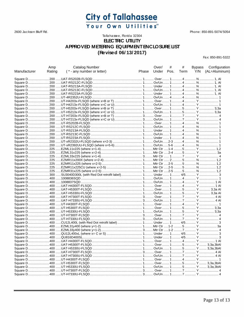
2600 Jackson Bluff Rd. Phone: 850-891-5074/5054
Tallahassee, Florida 32304 ELECTRIC UTILITY
APPROVED METERING EQUIPMENT ENCLOSURE LIST (Revised 06/13/2017)
Fax: 850-891-5322
Amp Catalog Number Over/ # # Bypass Configuration Manufacturer Rating ( * - any number or letter) Phase Under Pos. Term Y/N (AL=Aluminum)
Page 13 of 13
Square D ....................... 200 ...... UAT-RS202B-FLSQD ...................................................... 1 .......... Over ........ 1 ........... 4 ............ N ................ 1, Al Square D ....................... 200 ...... UAT-RS212C-FLSQD ...................................................... 1 ......... Ov/Un ....... 1 ........... 4 ............ N ................ 1, Al Square D ....................... 200 ...... UAT-RS213A-FLSQD ...................................................... 1 ......... Under ....... 1 ........... 4 ............ N ................ 1, Al Square D ....................... 200 ...... UAT-RS213C-FLSQD ...................................................... 1 ......... Ov/Un ....... 1 ........... 4 ............ N ................ 1, Al Square D ....................... 200 ...... UAT-RS223A-FLSQD ...................................................... 1 ......... Under ....... 1 ........... 4 ............ N ................ 1, Al Square D ....................... 200 ...... UT-4R2352U-FLSQD ....................................................... 1 ......... Ov/Un ....... 4 ........... 4 ............ N ..................... 1 Square D ....................... 200 ...... UT-H4203x-FLSQD (where x=B or T) .............................. 1 .......... Over ........ 1 ........... 4 ............ Y ..................... 1 Square D ....................... 200 ...... UT-H4213x-FLSQD (where x=C or U) .............................. 1 ......... Ov/Un ....... 1 ........... 4 ............ Y ..................... 1 Square D ....................... 200 ...... UT-H5203x-FLSQD (where x=B or T) .............................. 1 .......... Over ........ 1 ........... 5 ............ Y ................ 3,3a Square D ....................... 200 ...... UT-H5213x-FLSQD (where x=C or U) .............................. 1 ......... Ov/Un ....... 1 ........... 5 ............ Y ................ 3,3a Square D ....................... 200 ...... UT-H7203x-FLSQD (where x=B or T) .............................. 3 .......... Over ........ 1 ........... 7 ............ Y ..................... 4 Square D ....................... 200 ...... UT-H7213x-FLSQD (where x=C or U) .............................. 3 ......... Ov/Un ....... 1 ........... 7 ............ Y ..................... 4 Square D ....................... 200 ...... UT-RS202B-FLSQD ......................................................... 1 .......... Over ........ 1 ........... 4 ............ N ..................... 1 Square D ....................... 200 ...... UT-RS212C-FLSQD ........................................................ 1 ......... Ov/Un ....... 1 ........... 4 ............ N ..................... 1 Square D ....................... 200 ...... UT-RS213A-FLSQD ......................................................... 1 ......... Under ....... 1 ........... 4 ............ N ..................... 1 Square D ....................... 200 ...... UT-RS213C-FLSQD ........................................................ 1 ......... Ov/Un ....... 1 ........... 4 ............ N ..................... 1 Square D ....................... 200 ...... UT-RS223A-FLSQD ......................................................... 1 ......... Under ....... 1 ........... 4 ............ N ..................... 1 Square D ....................... 200 ...... UT-xR2332U-FLSQD (where x=2-3) ................................ 1 ......... Ov/Un ......2-3 ......... 4 ............ N ..................... 1 Square D ....................... 200 ...... UT-xR2392UU-FLSQD (where x=5-6) .............................. 1 ......... Ov/Un ......5-6 ......... 4 ............ N ..................... 1 Square D ....................... 225 ...... EZML11x225 (where x=1-4) ............................................. 1 ......... Mtr Ctr .....1-4 ......... 5 ............ Y .................. 1,2 Square D ....................... 225 ...... EZML31x225 (where x=2-4) ............................................. 1 ......... Mtr Ctr .....2-4 ......... 5 ............ Y ................... 3a Square D ....................... 225 ...... EZML33x225 (where x=1-4) ............................................. 3 ......... Mtr Ctr ...... 1 ........... 7 ............ Y ..................... 4 Square D ....................... 225 ...... EZMR11x200X (where x=2-4) .......................................... 1 ......... Mtr Ctr ...... 2 ........... 5 ............ N .................. 1,2 Square D ....................... 225 ...... EZMR11x225 (where x=2-5) ............................................ 1 ......... Mtr Ctr .....2-5 ......... 5 ............ N .................. 1,2 Square D ....................... 225 ...... EZMR11x225CU (where x=2-5) ....................................... 1 ......... Mtr Ctr .....2-5 ......... 5 ............ N .................. 1,2 Square D ....................... 225 ...... EZMR31x225 (where x=2-5) ............................................ 1 ......... Mtr Ctr .....2-5 ......... 5 ............ N .................. 1,2 Square D ....................... 300 ...... SU3040D300L (with Red Dot retrofit label) ....................... 1 ......... Under ....... 1 ......... 4/5 ........... Y ..................... 3 Square D ....................... 400 ...... 1008836SQD ................................................................... 1 ......... Ov/Un ....... 1 ........... 4 ............ Y ..................... 1 Square D ....................... 400 ...... 1008837SQD ................................................................... 1 ......... Ov/Un ....... 1 ........... 4 ............ Y ................. 1 Al Square D ....................... 400 ...... UAT-H4300T-FLSQD ....................................................... 1 .......... Over ........ 1 ........... 4 ............ Y ................. 1 Al Square D ....................... 400 ...... UAT-H5300T-FLSQD ....................................................... 1 .......... Over ........ 1 ........... 5 ............ Y ............ 3,3a Al Square D ....................... 400 ...... UAT-H5330U-FLSQD ...................................................... 1 ......... Ov/Un ....... 1 ........... 5 ............ Y ............ 3,3a Al Square D ....................... 400 ...... UAT-H7300T-FLSQD ....................................................... 3 .......... Over ........ 1 ........... 7 ............ Y ................. 4 Al Square D ....................... 400 ...... UAT-H7330U-FLSQD ...................................................... 3 ......... Ov/Un ....... 1 ........... 7 ............ Y ................. 4 Al Square D ....................... 400 ...... UT-H4300T-FLSQD ......................................................... 1 .......... Over ........ 1 ........... 4 ............ Y ..................... 1 Square D ....................... 400 ...... UT-H5300T-FLSQD ......................................................... 1 .......... Over ........ 1 ........... 5 ............ Y ................ 3,3a Square D ....................... 400 ...... UT-H5330U-FLSQD ......................................................... 1 ......... Ov/Un ....... 1 ........... 5 ............ Y ................ 3,3a Square D ....................... 400 ...... UT-H7300T-FLSQD ......................................................... 3 .......... Over ........ 1 ........... 7 ............ Y ..................... 4 Square D ....................... 400 ...... UT-H7330U-FLSQD ......................................................... 3 ......... Ov/Un ....... 1 ........... 7 ............ Y ..................... 4 Square D ....................... 400 ...... CU12L400L (with Red Dot retrofit label) ........................... 1 ......... Under ....... 1 ......... 4/5 ........... Y ..................... 3 Square D ....................... 400 ...... EZML31y400 (where y=1-2) ............................................. 1 ......... Mtr Ctr .....1-2 ......... 5 ............ Y ................... 3a Square D ....................... 400 ...... EZML33y400 (where y=1-2) ............................................. 3 ......... Mtr Ctr .....1-2 ......... 7 ............ Y ..................... 4 Square D ....................... 400 ...... QU12L400xL (where x= C or S) ....................................... 1 ......... Under ....... 1 ......... 4/5 ........... Y ..................... 3 Square D ....................... 400 ...... QU816D400SL ................................................................. 1 ......... Under ....... 1 ......... 4/5 ........... Y ..................... 3 Square D ....................... 400 ...... UAT-H4300T-FLSQD ....................................................... 1 .......... Over ........ 1 ........... 4 ............ Y ................. 1 Al Square D ....................... 400 ...... UAT-H5300T-FLSQD ....................................................... 1 .......... Over ........ 1 ........... 5 ............ Y ........ 3,3a,3bAl Square D ....................... 400 ...... UAT-H5330U-FLSQD ...................................................... 1 ......... Ov/Un ....... 1 ........... 5 ............ Y ........ 3,3a,3bAl Square D ....................... 400 ...... UAT-H7300T-FLSQD ....................................................... 3 .......... Over ........ 1 ........... 7 ............ Y ................. 4 Al Square D ....................... 400 ...... UAT-H7300U-FLSQD ...................................................... 1 ......... Ov/Un ....... 1 ........... 7 ............ Y ................. 4 Al Square D ....................... 400 ...... UT-H4300T-FLSQD ......................................................... 1 .......... Over ........ 1 ........... 4 ............ Y ..................... 1 Square D ....................... 400 ...... UT-H5300T-FLSQD ......................................................... 1 .......... Over ........ 1 ........... 5 ............ Y ........ 3,3a,3bAl Square D ....................... 400 ...... UT-H5330U-FLSQD ......................................................... 1 ......... Ov/Un ....... 1 ........... 5 ............ Y ........ 3,3a,3bAl Square D ....................... 400 ...... UT-H7300T-FLSQD ......................................................... 3 .......... Over ........ 1 ........... 7 ............ Y ..................... 4 Square D ....................... 400 ...... UT-H7330U-FLSQD ......................................................... 3 ......... Ov/Un ....... 1 ........... 7 ............ Y ..................... 4

Page 0 of 1
11. APPENDIX B – EASEMENT AND RIGHT-OF-WAY POLICY

TRANSMISSION EASEMENT / RIGHT -OF-WAY POLICY 1 | P a g e
CITY OF TALLAHASSEE ELECTRIC & GAS UTILITY
ELECTRIC TRANSMISSION EASEMENT / RIGHT-OF-WAY POLICY CITY RIGHTS:
An electric utility easement/right-of-way, whether acquired through purchase, donation, or eminent domain provides for the use by the City of specified property for the construction, operation and maintenance of its electric power lines. A Transmission Right of Way is defined as property owned by the City with transmission lines located on the property. A Transmission Easement grants to the City rights to use specified property not owned by the City for placement of transmission facilities. The rights acquired, as specified in the Transmission Easement, will generally include, but may not necessarily be limited to, the right of unlimited access necessary to patrol and maintain, the right to enlarge, replace, add to, delete from, and construct additional power lines within easement/right-of-way limits. In addition, the City has the right to set reasonable standards of use necessary to preserve the unencumbered ability of the City to maintain existing and construct future power lines within its easement/right-of-way boundaries.
All activity within the easement/right-of-way shall be reviewed by an Electric & Gas Power Delivery Engineer to obtain prior written approval. Engineering plans may be required. Compliance with this Policy or approval of any plans by Power Delivery does not mean that the requirements of any local, county, state or federal government or other applicable agency with governing authority have been satisfied. OWNER RIGHTS (EASEMENT):
The property owner has the right generally to utilize the Transmission Easement for any use or purpose which does not interfere with the City’s rights. All fencing and lighting of Transmission Easements must be approved in writing by a Power Delivery Engineer and allow access for City vehicles. Transmission Easements must have 16-foot-wide gates installed for access. All gates must be maintained by the Owner to be in good working condition. If the gate is to be locked, the city shall supply a lock to be installed in a “double lock” system with the customer's lock for access purposes. PERMITTED USE:
I. GENERAL Transmission facilities are designed, constructed, and maintained to be inherently
safe; however, these same facilities also represent a life safety risk. If a person makes contact with an energized conductor in the air or an energized conductor makes contact with the ground near a person, then injury, death, or permanent disability may result from this mechanical or electrical (including touch or step potential) hazard. Citizens utilize space near high voltage transmission facilities at their own risk.
Conductive materials (metal) may develop induced currents from the high magnetic fields of nearby transmission lines. It is recommended that conductive materials not be installed in the transmission easement / right-of-way. If conductive materials are used (fencing,

TRANSMISSION EASEMENT / RIGHT -OF-WAY POLICY 2 | P a g e
CITY OF TALLAHASSEE ELECTRIC & GAS UTILITY
lighting, etc.…), then a grounding system designed by a professional engineer to ground metal to twenty-five (25) ohms or less should be installed.
The City does not have the right to grant access across Transmission Easements. Citizens must contact the owner of the property underlying the easement to request access.
At the City’s sole discretion, the City may grant access across Transmission Right-of-Way to citizens for limited use. An access agreement between the grantee and the City must be executed and recorded prior to utilization of the granted access.
All activities in the Transmission Easement or Transmission Right-of-Way should be limited such that materials or equipment (cranes, raised dump truck beds, high antenna, canopies that can be blown away by the wind, kites, etc.) do not come near the energized conductors.
Such access, when granted, shall be subject to termination at any time at the discretion of the City.
II. NON-EXCLUSIVE EXAMPLES of PERMITTED USES:
Grow and cultivate crops. Parking area. Recreational area. Roadway or driveway. Graze livestock.
NON-PERMITTED USES
I. All Zones Attachments to transmission structures. Burning of fire for any reason. Any drainage feature that causes erosion, directs storm water toward the rights of way,
or limits access to or around City facilities. Any construction, excavation, or any temporary or permanent activities in the
Transmission Easement or Transmission Right-of-Way near City poles, structures, guys, guy anchors, or electrical facilities above or below surface which will prevent unemcumbered equipment access or creating ground-to-conductor clearance violations.
II. IN THE WIRE AND BORDER ZONES:
Satellite systems, swimming pools (and any associated equipment and decking), graves, billboards, dumpsters, signs, wells, deer stands, septic systems or tanks (whether above or below ground), debris of any type, flammable material, building material, or wrecked or disabled vehicles.
Manholes, water valves, water meters, backflow preventers, irrigation heads, transformers, telephone/cable pedestals (and associated equipment) and fire hydrants.
Planting of trees or landscaping. Storage or stockpiling of dirt or any other material.

TRANSMISSION EASEMENT / RIGHT -OF-WAY POLICY 3 | P a g e
CITY OF TALLAHASSEE ELECTRIC & GAS UTILITY
Fences, gates, and light fixtures shall not exceed 10 feet in height and shall be installed greater than 25 feet from poles, towers and guy anchors. The location of any fence gate or opening is subject to City approval to ensure adequate access for maneuvering. The property owner is required to install a City lock on the gate to ensure access. The City shall supply a lock to be installed in a “double lock” system.
All grading fills and grading cuts (lakes, ponds, retention or detention facilities, etc.) are restricted and may only be approved in writing by the City as a special exception prior to construction. Where approved cuts must be a minimum distance of seventy-five (75’) feet from poles, towers, guys and anchors. Grading fill shall be no closer than twenty-five (25’) feet from poles, towers, guys and anchors and the slope shall not exceed 4:1. Grading cuts and fills shall not limit access or maneuvering along the Transmission Easement or Transmission Right-of-Way. Poles and structures must be accessible from a predetermined access strip. Generally, it is necessary for the City to have adequate access to the Transmission Easement or Transmission Right-of-Way boundaries for large equipment to transport and maneuver sixty to one hundred and twenty (60’- 120’) foot long poles and to perform tree trimming.
III. IN THE WIRE ZONE:
Structures, buildings, manufactured/mobile homes, retaining walls, and all other objects (whether above or below ground) which in the City’s sole opinion interfere with the Transmission Easement or Transmission Right-of-Way.
DAMAGES & LIABILITY (EASEMENT):
Construction or installation of any paving, landscaping, or improvements placed within the easement either above or below ground is subject to the City’s rights of ingress, egress, maintenance and construction. The City is not responsible for any damage to such facilities caused by its personnel or equipment in the pursuit of necessary work. Consequently, it is to the owner’s advantage to make certain that improvements (paving, etc.) will support the weight of City maintenance and construction equipment and will accommodate the City’s method of work and possible future expansion of facilities. The City cannot guarantee that wires, poles, or structures will not fall and damage improvements placed on the Transmission Easement or Transmission Right-of-Way or cause injury to anyone present or property; nor will the City assume any associated cost or liability for these damages. Any use of Transmission Rights-of-Way or Transmission Easements by others shall be at such other person’s or entity’s sole risk and liability. Further, the City will assume no cost to remove, relocate, or replace any improvement installed or placed on within the Transmission Easement or Transmission Right-of-Way should new construction, maintenance, or the City’s need so dictate.

TRANSMISSION EASEMENT / RIGHT -OF-WAY POLICY 4 | P a g e
CITY OF TALLAHASSEE ELECTRIC & GAS UTILITY
APPROVAL PROCESS (EASEMENT):
Proposed improvements must be submitted in writing to the Electric & Gas Utility complete with a project narrative and plans that include the location of easement/right-of-way boundary, existing structures and facilities, and the proposed improvements with project limits. Electric & Gas Utility personnel are available on reasonable notice to review the proposed work with owners, prior to formal submission of plans. Correspondence or questions should be directed as follows:
City of Tallahassee Electric & Gas Utility Power Delivery Division 2602 Jackson Bluff Road Tallahassee, FL 32304-4408 Attention: Mike Drymon Telephone: (850) 891-5525 [email protected]
Version Date Synopsis Division SME Original Original Power Delivery
R1 9/10/19 Revised to conform to industry standard practice. Power Delivery WAIR2 9/4/20 Add recommend tree species list Power Delivery WAIR3 10/13/20 Legal review update Power Delivery WAI
NOTE: New or revised requirements of this policy are not retroactive to work completed under prior version requirements of the policy unless a life safety, law, or regulatory requirement dictate otherwise.
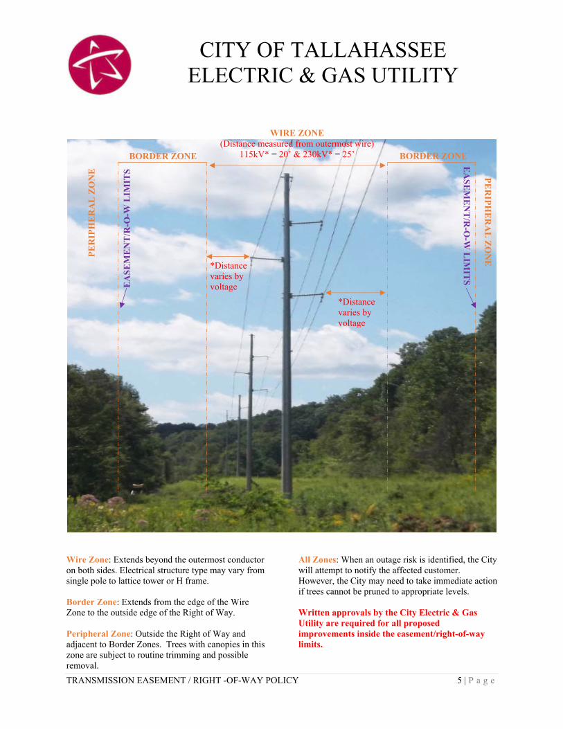
TRANSMISSION EASEMENT / RIGHT -OF-WAY POLICY 5 | P a g e
CITY OF TALLAHASSEE ELECTRIC & GAS UTILITY
Wire Zone: Extends beyond the outermost conductor on both sides. Electrical structure type may vary from single pole to lattice tower or H frame. Border Zone: Extends from the edge of the Wire Zone to the outside edge of the Right of Way. Peripheral Zone: Outside the Right of Way and adjacent to Border Zones. Trees with canopies in this zone are subject to routine trimming and possible removal.
All Zones: When an outage risk is identified, the City will attempt to notify the affected customer. However, the City may need to take immediate action if trees cannot be pruned to appropriate levels. Written approvals by the City Electric & Gas Utility are required for all proposed improvements inside the easement/right-of-way limits.
WIRE ZONE (Distance measured from outermost wire)
115kV* = 20’ & 230kV* = 25’
*Distance varies by voltage
*Distance varies by voltage
BORDER ZONE BORDER ZONE
PE
RIP
HE
RA
L Z
ON
E
PE
RIP
HE
RA
L Z
ON
E
EA
SE
ME
NT
/R-O
-W L
IMIT
S E
AS
EM
EN
T/R
-O-W
LIM
ITS

TRANSMISSION EASEMENT / RIGHT -OF-WAY POLICY 6 | P a g e
CITY OF TALLAHASSEE ELECTRIC & GAS UTILITY
RECOMMENDED TREE SPECIES LIST
Electric Utilities must comply with Federal regulations as mandated by NERC under FAC003-4. In compliance with these regulations, every three years trimming will be performed 20’ from the outermost 115KV conductor on either side of the line. Trimming will be performed up to 30’ (depending on the span) from the outermost 230KV conductor on either side of the line. Further, trees may be removed beyond the 20’-30’ trimmed areas in the periphery zone if the department’s forester identifies them as a “danger tree”. Danger trees are less likely to develop if plantings are made with certain tree species.
Tallahassee Electric & Gas Utility recommend the tree species listed below when planting in the periphery zones adjacent to electric facilities:
Southern Flowering Crabapple Tree Sparkleberry Fringe Tree Japanese Maple var. “Blood Good” May Hawthorne (Mayhaw) Red Buckeye Crepe Myrtles: Choose from the following varieties: white - “Acoma” or “Burgundy Cotton” purple - “Catawba” or “Zuni” pink - “Sioux”, “Hopi”, or “Pink Velour” red - “Tonto”, “Cheyenne” or “Arapahoe” lavender - “Yuma” “Star” Magnolia Chickasaw Plum Yellow Anise Burford Holly Weeping Yaupon Holly Tea Olive Wax Myrtle Salt Bush Confederate Rose

Page 53
12. APPENDIX C – STANDARD FIGURES
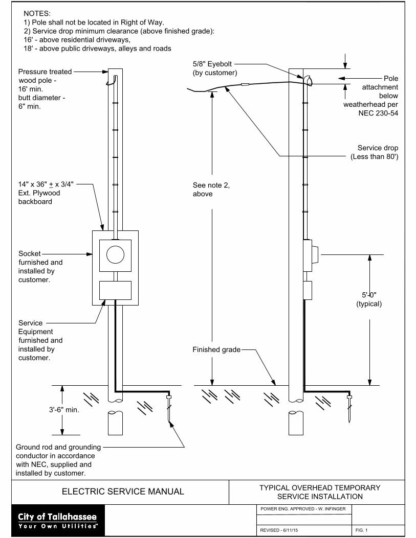
ELECTRIC SERVICE MANUAL
TYPICAL OVERHEAD TEMPORARY
SERVICE INSTALLATION
REVISED - 6/11/15
POWER ENG. APPROVED - W. INFINGER
FIG. 1
NOTES:
1) Pole shall not be located in Right of Way.
2) Service drop minimum clearance (above finished grade):
16' - above residential driveways,
18' - above public driveways, alleys and roads
Pressure treated
wood pole -
16' min.
butt diameter -
6" min.
14" x 36" + x 3/4"
Ext. Plywood
backboard
Socket
furnished and
installed by
customer.
Service
Equipment
furnished and
installed by
customer.
5/8" Eyebolt
(by customer)
See note 2,
above
Finished grade
Pole
attachment
below
weatherhead per
NEC 230-54
Service drop
(Less than 80')
5'-0"
(typical)
3'-6" min.
Ground rod and grounding
conductor in accordance
with NEC, supplied and
installed by customer.
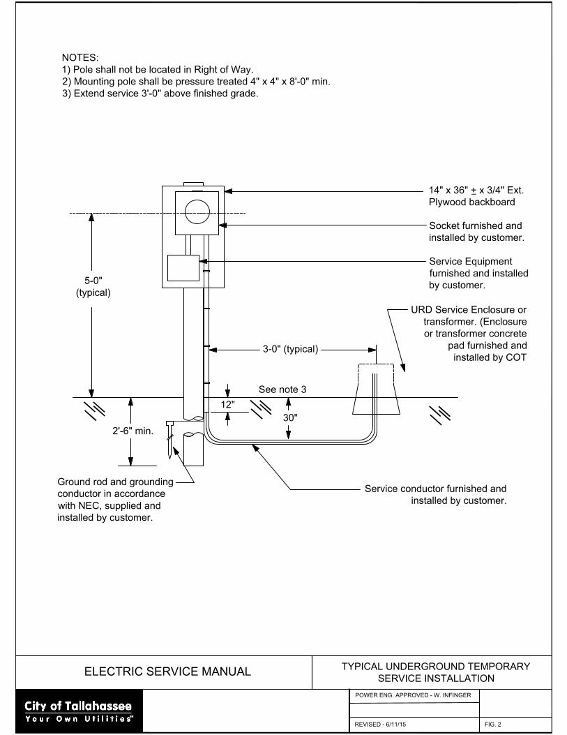
ELECTRIC SERVICE MANUAL
TYPICAL UNDERGROUND TEMPORARY
SERVICE INSTALLATION
REVISED - 6/11/15
POWER ENG. APPROVED - W. INFINGER
FIG. 2
NOTES:
1) Pole shall not be located in Right of Way.
2) Mounting pole shall be pressure treated 4" x 4" x 8'-0" min.
3) Extend service 3'-0" above finished grade.
14" x 36" + x 3/4" Ext.
Plywood backboard
Socket furnished and
installed by customer.
Service Equipment
furnished and installed
by customer.
2'-6" min.
Ground rod and grounding
conductor in accordance
with NEC, supplied and
installed by customer.
12"
3-0" (typical)
30"
See note 3
URD Service Enclosure or
transformer. (Enclosure
or transformer concrete
pad furnished and
installed by COT
Service conductor furnished and
installed by customer.
5-0"
(typical)
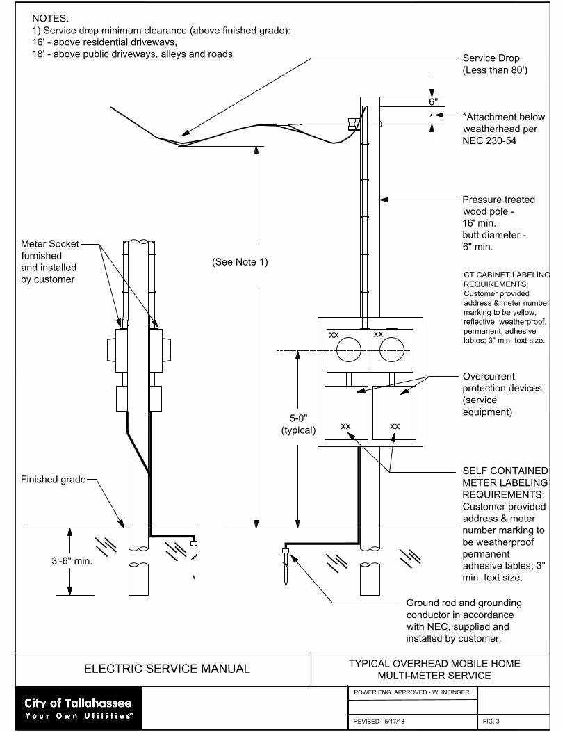
ELECTRIC SERVICE MANUAL
TYPICAL OVERHEAD MOBILE HOME
MULTI-METER SERVICE
REVISED - 5/17/18
POWER ENG. APPROVED - W. INFINGER
FIG. 3
NOTES:
1) Service drop minimum clearance (above finished grade):
16' - above residential driveways,
18' - above public driveways, alleys and roads
Service Drop
(Less than 80')
*Attachment below
weatherhead per
NEC 230-54
Pressure treated
wood pole -
16' min.
butt diameter -
6" min.
Overcurrent
protection devices
(service
equipment)
SELF CONTAINED
METER LABELING
REQUIREMENTS:
Customer provided
address & meter
number marking to
be weatherproof
permanent
adhesive lables; 3"
min. text size.
Ground rod and grounding
conductor in accordance
with NEC, supplied and
installed by customer.
3'-6" min.
Meter Socket
furnished
and installed
by customer
Finished grade
5-0"
(typical)
(See Note 1)
6"
*
xx
xx
CT CABINET LABELING
REQUIREMENTS:
Customer provided
address & meter number
marking to be yellow,
reflective, weatherproof,
permanent, adhesive
lables; 3" min. text size.
xxxx
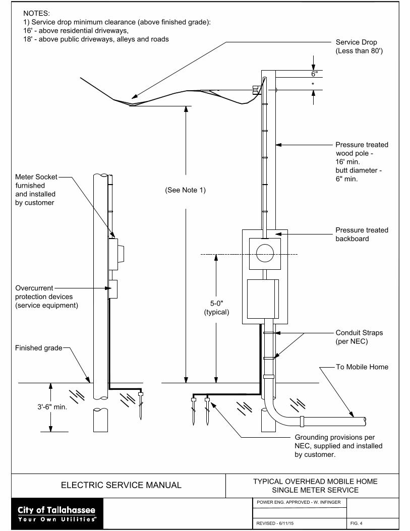
ELECTRIC SERVICE MANUAL
TYPICAL OVERHEAD MOBILE HOME
SINGLE METER SERVICE
REVISED - 6/11/15
POWER ENG. APPROVED - W. INFINGER
FIG. 4
NOTES:
1) Service drop minimum clearance (above finished grade):
16' - above residential driveways,
18' - above public driveways, alleys and roads
Grounding provisions per
NEC, supplied and installed
by customer.
3'-6" min.
Meter Socket
furnished
and installed
by customer
Overcurrent
protection devices
(service equipment)
Finished grade
5-0"
(typical)
(See Note 1)
6"
*
Service Drop
(Less than 80')
Pressure treated
wood pole -
16' min.
butt diameter -
6" min.
Pressure treated
backboard
Conduit Straps
(per NEC)
To Mobile Home
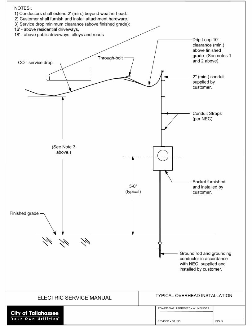
ELECTRIC SERVICE MANUAL
TYPICAL OVERHEAD INSTALLATION
REVISED - 6/11/15
POWER ENG. APPROVED - W. INFINGER
FIG. 5
NOTES:.
1) Conductors shall extend 2' (min.) beyond weatherhead.
2) Customer shall furnish and install attachment hardware.
3) Service drop minimum clearance (above finished grade):
16' - above residential driveways,
18' - above public driveways, alleys and roads
Ground rod and grounding
conductor in accordance
with NEC, supplied and
installed by customer.
5-0"
(typical)
Drip Loop 10'
clearance (min.)
above finished
grade. (See notes 1
and 2 above).
2" (min.) conduit
supplied by
customer.
Conduit Straps
(per NEC)
Socket furnished
and installed by
customer.
(See Note 3
above.)
Finished grade
COT service drop
Through-bolt

ELECTRIC SERVICE MANUAL
TYPICAL SERVICE MAST INSTALLATION
REVISED - 6/24/15
POWER ENG. APPROVED - W. INFINGER
FIG. 6
NOTES:
1) Any service mast exceeding 3 feet in height above the roof or last means of support shall be adequately guyed.
2) Conductors shall extend 2 feet (min.) beyond weatherhead in accordance with paragraph 2.2.5
Ground rod and grounding
conductor in accordance
with NEC, supplied and
installed by customer.
5-0"
(typical)
Weatherhead and
accessory
hardware supplied
and installed by
customer.
Roof
Conduit Straps
(per NEC)
2" (min.) conduit
furnished and
installed by
customer.
Socket furnished
and installed by
customer.
Service drop minimum clearance
(above finished grade):
16' - above residential driveways
18' - above public driveways,
alleys and roads
Finished grade
(See notes 1 and 2 above.)
18" min. 36" max.
48" max.
DRIP LOOP
(unless guyed)
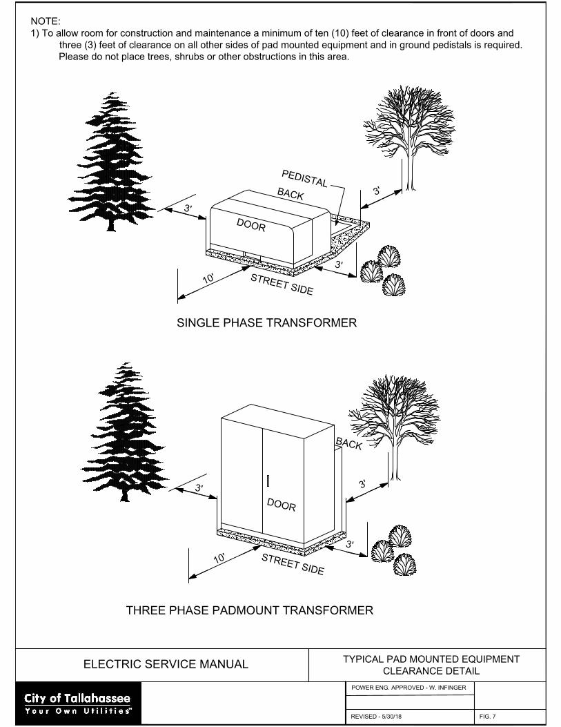
ELECTRIC SERVICE MANUAL
TYPICAL PAD MOUNTED EQUIPMENT
CLEARANCE DETAIL
REVISED - 5/30/18
POWER ENG. APPROVED - W. INFINGER
FIG. 7
NOTE:
1) To allow room for construction and maintenance a minimum of ten (10) feet of clearance in front of doors and
three (3) feet of clearance on all other sides of pad mounted equipment and in ground pedistals is required.
Please do not place trees, shrubs or other obstructions in this area.
3
'
D
O
O
R
3
'
1
0
' S
T
R
E
E
T
S
ID
E
3
'
D
O
O
R
3
'
1
0
' S
T
R
E
E
T
S
ID
E
3
'
B
A
C
K
THREE PHASE PADMOUNT TRANSFORMER
SINGLE PHASE TRANSFORMER
B
A
C
K
3
'
P
E
D
IS
T
A
L
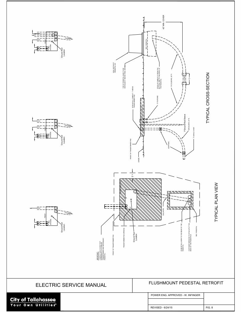
ELECTRIC SERVICE MANUAL
FLUSHMOUNT PEDESTAL RETROFIT
REVISED - 6/24/15
POWER ENG. APPROVED - W. INFINGER
FIG. 8
2"
3"
3"
42
" M
IN
. C
OV
ER
TO
P O
F P
ED
ES
TA
L B
AS
E T
O B
E
IN
ST
ALLE
D 2" A
BO
VE
F
IN
AL G
RA
DE
ST
UB
U
P A
LL C
ON
DU
IT
1" A
BO
VE
TR
AN
SF
OR
ME
R P
AD
ST
UB
U
P C
ON
DU
IT
4" F
RO
M T
HE
BO
TT
OM
, A
ND
T
O T
HE
R
EA
R, O
F
TH
E P
ED
ES
TA
L
TR
AN
SF
OR
ME
R P
AD
SE
C. P
ED
ES
TA
L
BU
LLH
OR
N
TR
AN
SF
OR
ME
R P
AD
SE
C. P
ED
ES
TA
L
TY
PIC
AL C
RO
SS
-S
EC
TIO
N
TY
PIC
AL P
LA
N V
IE
W
FR
ON
T O
F T
RA
NS
FO
RM
ER
P
AD
TR
AN
SF
OR
ME
R P
AD
O
PE
NIN
G
ST
UB
U
P B
ULLH
OR
N T
O T
HE
R
EA
R O
F T
HE
PE
DE
ST
AL
FR
ON
T O
F T
RA
NS
FO
RM
ER
P
AD
CU
ST
OM
ER
S
ER
VIC
ES
T
O S
TU
B U
P A
T T
HE
BA
CK
O
F T
HE
P
ED
ES
TA
LS
3"
2"
IM
PO
RT
AN
T:
CO
MP
AC
T S
OIL IN
O
NE
F
OO
T
IN
CR
EM
EN
TS
T
O S
TA
BILIZ
E
TR
AN
SF
OR
ME
R A
ND
S
EC
ON
DA
RY
PE
DE
ST
AL.
GR
AD
E
6"
typ
BU
LLH
OR
NS
3" C
OU
PLIN
G
T
O
P
E
D
3"
3"
OP
EN
IN
G
PA
D
3"
3"
FR
ON
T
2"
2"
OP
EN
IN
G
T
O
P
E
D
PA
D
2"
2"
3"
3"
3"
FR
ON
T
P
E
D
T
O
OP
EN
IN
G
FR
ON
T
2"
PA
D
2"
3"
3"
12"
20"
NE
W, R
ET
RO
FIT
PE
DE
ST
AL LID
2" prim
ary conduit
AD
AP
TE
RS
GR
S E
LB
OW
, 24" R
.
PV
C E
LB
OW
S, 36" R
.
12"
1"G
ro
un
d R
od
S
le
eve
Gro
un
d R
od
Lo
ca
tio
n
Gro
un
d R
od
Lo
ca
tio
n
Gro
un
d R
od
Lo
ca
tio
n
Gro
un
d R
od
Lo
ca
tio
n
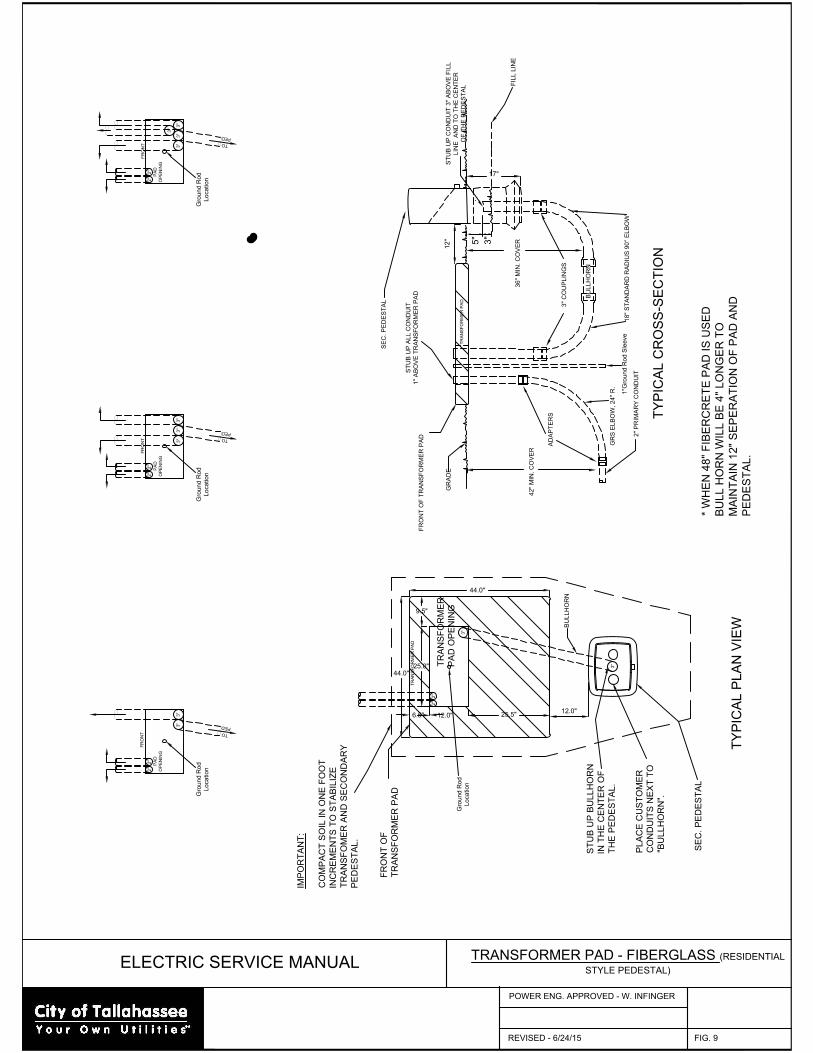
3"
BU
LL
HO
RN
2"
2"
TY
PIC
AL P
LA
N V
IE
W
3"
T
O
P
E
D
2"
OP
EN
IN
G
2"
FR
ON
T
PA
D
3"
P
E
D
T
O
3"
3"
3"
3"
2"
OP
EN
IN
G
2"
FR
ON
T
PA
D
3"
TO
P
E
D
2"
OP
EN
IN
G
2"
FR
ON
T
PA
D
3"
3"
9.5"
6.5"
25.0"
44.0"
TR
AN
SF
OR
ME
R
PA
D O
PE
NIN
G
25.5"
12.0"
3"
TR
AN
SF
OR
ME
R P
AD
44.0"
12.0"
TY
PIC
AL C
RO
SS
-S
EC
TIO
N
GR
S E
LB
OW
, 2
4" R
.
2" P
RIM
AR
Y C
ON
DU
IT
AD
AP
TE
RS
FR
ON
T O
F T
RA
NS
FO
RM
ER
P
AD
GR
AD
E
42
" M
IN
. C
OV
ER
18
" S
TA
ND
AR
D R
AD
IU
S 9
0° E
LB
OW
ST
UB
U
P A
LL
C
ON
DU
IT
1" A
BO
VE
T
RA
NS
FO
RM
ER
P
AD
3" C
OU
PL
IN
GS
SE
C. P
ED
ES
TA
L
TR
AN
SF
OR
ME
R P
AD
12
"
36
" M
IN
. C
OV
ER
BU
LL
HO
RN
ST
UB
U
P C
ON
DU
IT
3
" A
BO
VE
F
IL
L
LIN
E A
ND
T
O T
HE
C
EN
TE
R
OF
T
HE
P
ED
ES
TA
L
17"
* W
HE
N 4
8" F
IB
ER
CR
ET
E P
AD
IS
U
SE
D
BU
LL
H
OR
N W
IL
L B
E 4
" L
ON
GE
R T
O
MA
IN
TA
IN
1
2" S
EP
ER
AT
IO
N O
F P
AD
A
ND
PE
DE
ST
AL
.
SE
C. P
ED
ES
TA
L
PL
AC
E C
US
TO
ME
R
CO
ND
UIT
S N
EX
T T
O
"B
UL
LH
OR
N".
ST
UB
U
P B
UL
LH
OR
N
IN
T
HE
C
EN
TE
R O
F
TH
E P
ED
ES
TA
L.
FR
ON
T O
F
TR
AN
SF
OR
ME
R P
AD
IM
PO
RT
AN
T:
CO
MP
AC
T S
OIL
IN
O
NE
F
OO
T
IN
CR
EM
EN
TS
T
O S
TA
BIL
IZ
E
TR
AN
SF
OM
ER
A
ND
S
EC
ON
DA
RY
PE
DE
ST
AL
.
1"G
ro
un
d R
od
S
le
eve
Gro
un
d R
od
Lo
ca
tio
n
Gro
un
d R
od
Lo
ca
tio
n
Gro
un
d R
od
Lo
ca
tio
n
Gro
un
d R
od
Lo
ca
tio
n
FIL
L L
IN
E
3"
5"
ELECTRIC SERVICE MANUAL
TRANSFORMER PAD - FIBERGLASS (RESIDENTIAL
STYLE PEDESTAL)
REVISED - 6/24/15
POWER ENG. APPROVED - W. INFINGER
FIG. 9
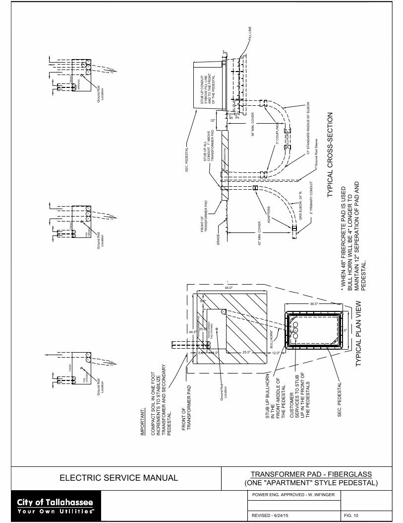
FR
ON
T O
F
TR
AN
SF
OR
ME
R P
AD
TY
PIC
AL P
LA
N V
IE
W
SE
C. P
ED
ES
TA
L
ST
UB
U
P B
UL
LH
OR
N
IN
T
HE
FR
ON
T-M
ID
DL
E O
F
TH
E P
ED
ES
TA
L
CU
ST
OM
ER
SE
RV
IC
ES
T
O S
TU
B
UP
IN
T
HE
F
RO
NT
O
F
TH
E P
ED
ES
TA
LS
BU
LL
HO
RN
*
2"
12.0"
36.5"
24.0"
42
" M
IN
. C
OV
ER
FR
ON
T O
F
TR
AN
SF
OR
ME
R P
AD
ST
UB
U
P C
ON
DU
IT
3"A
BO
VE
F
IL
L L
IN
E
AN
D T
O T
HE
F
RO
NT
OF
T
HE
P
ED
ES
TA
L
TY
PIC
AL C
RO
SS
-S
EC
TIO
N
TR
AN
SF
OR
ME
R P
AD
2" P
RIM
AR
Y C
ON
DU
IT
36
" M
IN
. C
OV
ER
12"
B
UL
LH
OR
N*
ST
UB
U
P A
LL
CO
ND
UIT
1
" A
BO
VE
TR
AN
SF
OR
ME
R P
AD
SE
C. P
ED
ES
TA
L
9.5"
6.5"
25.0"
44.0"
TR
AN
SF
OR
ME
R
PA
D O
PE
NIN
G
25.5"
12.0"
TR
AN
SF
OR
ME
R P
AD
44.0"
3"
3" C
OU
PL
IN
GS
13
" S
TA
ND
AR
D R
AD
IU
S 9
0° E
LB
OW
GR
S E
LB
OW
, 2
4" R
.
AD
AP
TE
RS
GR
AD
E
IM
PO
RT
AN
T:
CO
MP
AC
T S
OIL
IN
O
NE
F
OO
T
IN
CR
EM
EN
TS
T
O S
TA
BIL
IZ
E
TR
AN
SF
OM
ER
A
ND
S
EC
ON
DA
RY
PE
DE
ST
AL
.
FR
ON
T
PA
D
OP
EN
IN
G
T
O
P
E
D
T
O
P
E
D
T
O
P
E
D
FR
ON
T
PA
D
OP
EN
IN
G
FR
ON
T
PA
D
OP
EN
IN
G
2"
2"
2"
3"
3"
3"
3"
3"
3"
3"
3"
3"
3"
2"
2"
2"
2"
3"
* W
HE
N 4
8" F
IB
ER
CR
ET
E P
AD
IS
U
SE
D
BU
LL
H
OR
N W
IL
L B
E 4
" L
ON
GE
R T
O
MA
IN
TA
IN
1
2" S
EP
ER
AT
IO
N O
F P
AD
A
ND
PE
DE
ST
AL
.
*
FIL
L L
IN
E
1"G
ro
un
d R
od
S
le
eve
Gro
un
d R
od
Lo
ca
tio
n
Gro
un
d R
od
Lo
ca
tio
n
Gro
un
d R
od
Lo
ca
tio
n
Gro
un
d R
od
Lo
ca
tio
n
3"
5"
ELECTRIC SERVICE MANUAL
TRANSFORMER PAD - FIBERGLASS
(ONE "APARTMENT" STYLE PEDESTAL)
REVISED - 6/24/15
POWER ENG. APPROVED - W. INFINGER
FIG. 10
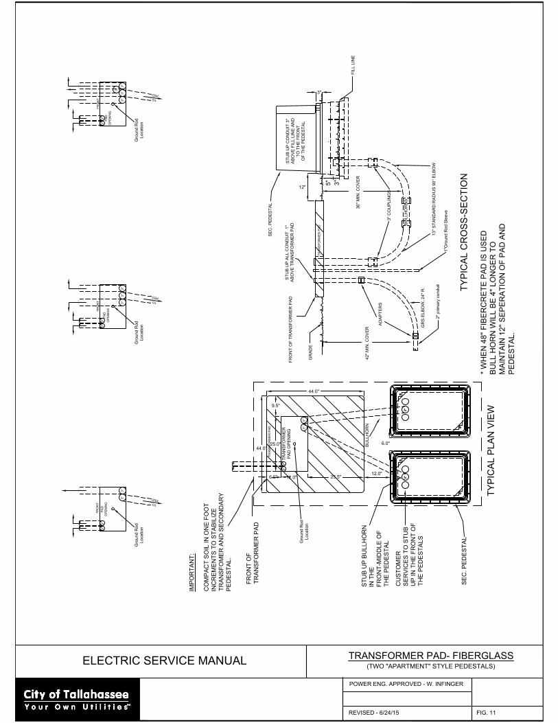
FR
ON
T O
F T
RA
NS
FO
RM
ER
P
AD
P
E
D
T
O
3"
3"
3"
OP
EN
IN
G
2"
2"
FR
ON
T
PA
D
3"
T
O
P
E
D
3"
OP
EN
IN
G
OP
EN
IN
G
2"
2"
FR
ON
T
PA
D
PA
D
TO
P
E
D
3"
3"
3"
3"
2"
2"
FR
ON
T
44.0"
TY
PIC
AL P
LA
N V
IE
W
TR
AN
SF
OR
ME
R
PA
D O
PE
NIN
G
BU
LL
HO
RN
2"
2"
44.0"
3"
3"
TR
AN
SF
OR
ME
R P
AD
3"
GR
AD
E
SE
C. P
ED
ES
TA
L
ST
UB
U
P C
ON
DU
IT
3
"
AB
OV
E F
IL
L L
IN
E A
ND
TO
T
HE
F
RO
NT
OF
T
HE
P
ED
ES
TA
L
TR
AN
SF
OR
ME
R P
AD
TY
PIC
AL C
RO
SS
-S
EC
TIO
N
2" p
rim
ary co
nd
uit
AD
AP
TE
RS
GR
S E
LB
OW
, 2
4" R
.
ST
UB
U
P A
LL
C
ON
DU
IT
1
"
AB
OV
E T
RA
NS
FO
RM
ER
P
AD
BU
LL
HO
RN
S
3" C
OU
PL
IN
GS
42
" M
IN
. C
OV
ER
3"
9.5"
6.5"12.0"
25.0"
25.5"
3"
3"
6.0"
12.0"
12"
36
" M
IN
. C
OV
ER
3"
* W
HE
N 4
8" F
IB
ER
CR
ET
E P
AD
IS
U
SE
D
BU
LL
H
OR
N W
IL
L B
E 4
" L
ON
GE
R T
O
MA
IN
TA
IN
1
2" S
EP
ER
AT
IO
N O
F P
AD
A
ND
PE
DE
ST
AL
.
SE
C. P
ED
ES
TA
L
CU
ST
OM
ER
SE
RV
IC
ES
T
O S
TU
B
UP
IN
T
HE
F
RO
NT
O
F
TH
E P
ED
ES
TA
LS
ST
UB
U
P B
UL
LH
OR
N
IN
T
HE
FR
ON
T-M
ID
DL
E O
F
TH
E P
ED
ES
TA
L
FR
ON
T O
F
TR
AN
SF
OR
ME
R P
AD
IM
PO
RT
AN
T:
CO
MP
AC
T S
OIL
IN
O
NE
F
OO
T
IN
CR
EM
EN
TS
T
O S
TA
BIL
IZ
E
TR
AN
SF
OM
ER
A
ND
S
EC
ON
DA
RY
PE
DE
ST
AL
.
13
" S
TA
ND
AR
D R
AD
IU
S 9
0° E
LB
OW
FIL
L L
IN
E
1"G
ro
un
d R
od
S
le
eve
Gro
un
d R
od
Lo
ca
tio
n
Gro
un
d R
od
Lo
ca
tio
n
Gro
un
d R
od
Lo
ca
tio
n
Gro
un
d R
od
Lo
ca
tio
n
3"
5"
ELECTRIC SERVICE MANUAL
TRANSFORMER PAD- FIBERGLASS
(TWO "APARTMENT" STYLE PEDESTALS)
REVISED - 6/24/15
POWER ENG. APPROVED - W. INFINGER
FIG. 11
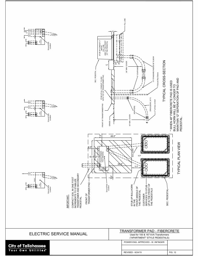
13
" S
TA
ND
AR
D R
AD
IU
S 9
0° E
LB
OW
IM
PO
RT
AN
T:
CO
MP
AC
T S
OIL
IN
O
NE
F
OO
T
IN
CR
EM
EN
TS
T
O S
TA
BIL
IZ
E
TR
AN
SF
OM
ER
A
ND
S
EC
ON
DA
RY
PE
DE
ST
AL
.
FR
ON
T O
F
TR
AN
SF
OR
ME
R P
AD
ST
UB
U
P B
UL
LH
OR
N
IN
T
HE
FR
ON
T-M
ID
DL
E O
F
TH
E P
ED
ES
TA
L
CU
ST
OM
ER
SE
RV
IC
ES
T
O S
TU
B
UP
IN
T
HE
F
RO
NT
O
F
TH
E P
ED
ES
TA
LS
SE
C. P
ED
ES
TA
L
* W
HE
N 4
8" F
IB
ER
CR
ET
E P
AD
IS
U
SE
D
BU
LL
H
OR
N W
IL
L B
E 4
" L
ON
GE
R T
O
MA
IN
TA
IN
1
2" S
EP
ER
AT
IO
N O
F P
AD
A
ND
PE
DE
ST
AL
.
3"
36
" M
IN
. C
OV
ER
12"
12.0"
6.0"
3"
3"
42
" M
IN
. C
OV
ER
3" C
OU
PL
IN
GS
BU
LL
HO
RN
S
ST
UB
U
P A
LL
C
ON
DU
IT
F
LU
SH
W
IT
H T
OP
O
F T
RA
NS
FO
RM
ER
P
AD
GR
S E
LB
OW
, 2
4" R
.
AD
AP
TE
RS
2" p
rim
ary co
nd
uit
TY
PIC
AL C
RO
SS
-S
EC
TIO
N
TR
AN
SF
OR
ME
R P
AD
ST
UB
U
P C
ON
DU
IT
3
"
AB
OV
E
FIL
L L
IN
E
AN
D T
O T
HE
F
RO
NT
OF
T
HE
P
ED
ES
TA
L
SE
C. P
ED
ES
TA
L
GR
AD
E
3"
TR
AN
SF
OR
ME
R P
AD
3"
2"
2"
BU
LL
HO
RN
TR
AN
SF
OR
ME
R
PA
D O
PE
NIN
G
TY
PIC
AL P
LA
N V
IE
W
FR
ON
T
2"
2"
3"
3"
3"
3"
P
E
D
TO
PA
D
PA
D
FR
ON
T
2"
2"
OP
EN
IN
G
OP
EN
IN
G
3"
P
E
D
T
O
3"
PA
D
FR
ON
T
2"
2"
OP
EN
IN
G
3"
3"
3"
T
O
P
E
D
FR
ON
T O
F T
RA
NS
FO
RM
ER
P
AD
FIL
L L
IN
E
42.0"
12.0"
29.5"
27.0"
6.5"
7.5
"
7.5
"
Gro
un
d R
od
Lo
ca
tio
n
48.0"
1"G
ro
un
d R
od
S
le
eve
Gro
un
d R
od
Lo
ca
tio
n
Gro
un
d R
od
Lo
ca
tio
n
Gro
un
d R
od
Lo
ca
tio
n
3"
5"
ELECTRIC SERVICE MANUAL
TRANSFORMER PAD - FIBERCRETE
Used for 100 & 167 kVA Transformers
("APARTMENT" STYLE PEDESTALS)
REVISED - 6/24/15
POWER ENG. APPROVED - W. INFINGER
FIG. 12
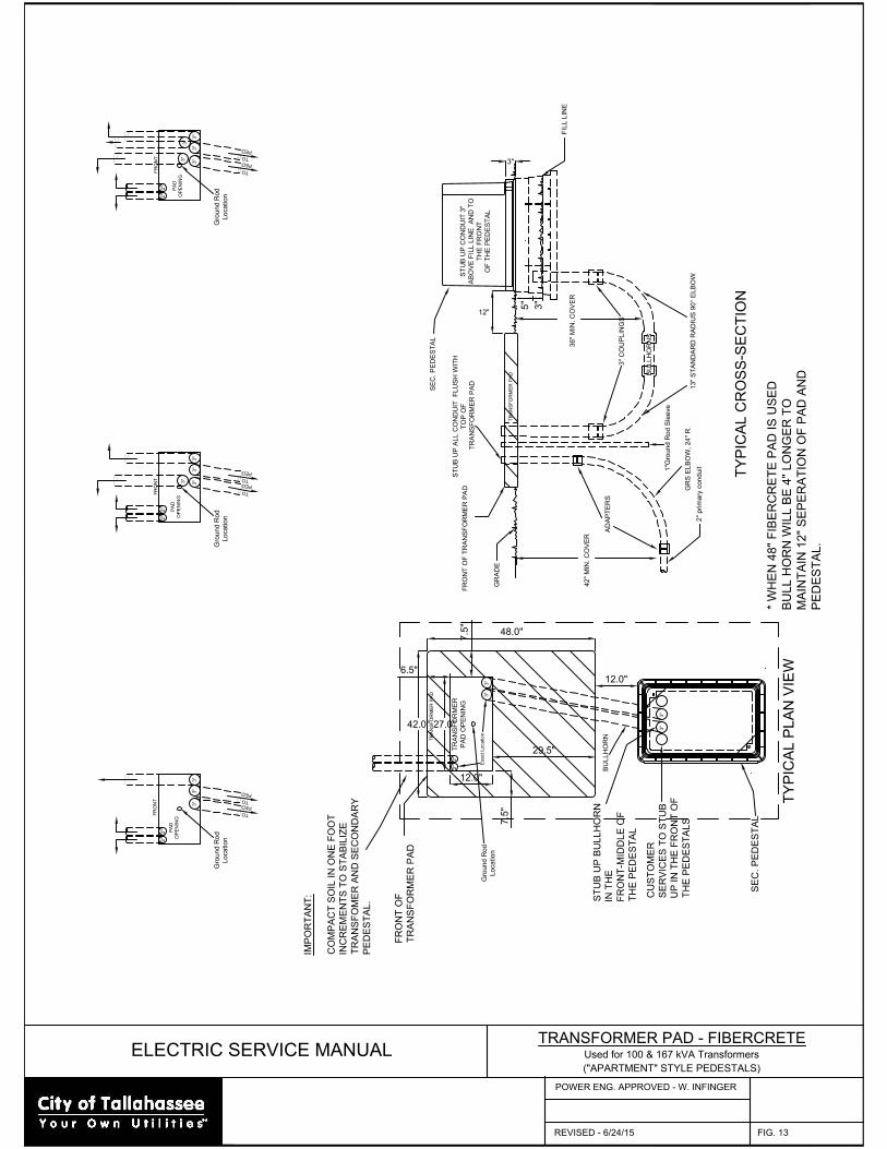
13
" S
TA
ND
AR
D R
AD
IU
S 9
0° E
LB
OW
IM
PO
RT
AN
T:
CO
MP
AC
T S
OIL
IN
O
NE
F
OO
T
IN
CR
EM
EN
TS
T
O S
TA
BIL
IZ
E
TR
AN
SF
OM
ER
A
ND
S
EC
ON
DA
RY
PE
DE
ST
AL
.
FR
ON
T O
F
TR
AN
SF
OR
ME
R P
AD
ST
UB
U
P B
UL
LH
OR
N
IN
T
HE
FR
ON
T-M
ID
DL
E O
F
TH
E P
ED
ES
TA
L
CU
ST
OM
ER
SE
RV
IC
ES
T
O S
TU
B
UP
IN
T
HE
F
RO
NT
O
F
TH
E P
ED
ES
TA
LS
SE
C. P
ED
ES
TA
L
* W
HE
N 4
8" F
IB
ER
CR
ET
E P
AD
IS
U
SE
D
BU
LL
H
OR
N W
IL
L B
E 4
" L
ON
GE
R T
O
MA
IN
TA
IN
1
2" S
EP
ER
AT
IO
N O
F P
AD
A
ND
PE
DE
ST
AL
.
3"
36
" M
IN
. C
OV
ER
12"
3"
3"
42
" M
IN
. C
OV
ER
3" C
OU
PL
IN
GS
BU
LL
HO
RN
S
ST
UB
U
P A
LL
C
ON
DU
IT
F
LU
SH
W
IT
H
TO
P O
F
T
RA
NS
FO
RM
ER
P
AD
GR
S E
LB
OW
, 2
4" R
.
AD
AP
TE
RS
2" p
rim
ary co
nd
uit
TY
PIC
AL C
RO
SS
-S
EC
TIO
N
TR
AN
SF
OR
ME
R P
AD
ST
UB
U
P C
ON
DU
IT
3
"
AB
OV
E F
IL
L L
IN
E A
ND
T
O
TH
E F
RO
NT
OF
T
HE
P
ED
ES
TA
L
SE
C. P
ED
ES
TA
L
GR
AD
E
3"
TR
AN
SF
OR
ME
R P
AD
3"
2"
2"
BU
LL
HO
RN
TR
AN
SF
OR
ME
R
PA
D O
PE
NIN
G
TY
PIC
AL P
LA
N V
IE
W
FR
ON
T
2"
2"
3"
3"
3"
3"
P
E
D
TO
PA
D
PA
D
FR
ON
T
2"
2"
OP
EN
IN
G
OP
EN
IN
G
3"
P
E
D
T
O
3"
PA
D
FR
ON
T
2"
2"
OP
EN
IN
G
3"
3"
3"
T
O
P
E
D
FR
ON
T O
F T
RA
NS
FO
RM
ER
P
AD
P
E
D
T
O
3"
P
E
D
T
O
3"
3"
T
O
P
E
D
FIL
L L
IN
E
48.0"
42.0" 27.0"
12.0"
29.5"
7.5
"
7.5
"
6.5"
12.0"
Exact Location
Gro
un
d R
od
Lo
ca
tio
n
1"G
ro
un
d R
od
S
le
eve
Gro
un
d R
od
Lo
ca
tio
n
Gro
un
d R
od
Lo
ca
tio
n
Gro
un
d R
od
Lo
ca
tio
n
3"
5"
ELECTRIC SERVICE MANUAL
TRANSFORMER PAD - FIBERCRETE
Used for 100 & 167 kVA Transformers
("APARTMENT" STYLE PEDESTALS)
REVISED - 6/24/15
POWER ENG. APPROVED - W. INFINGER
FIG. 13
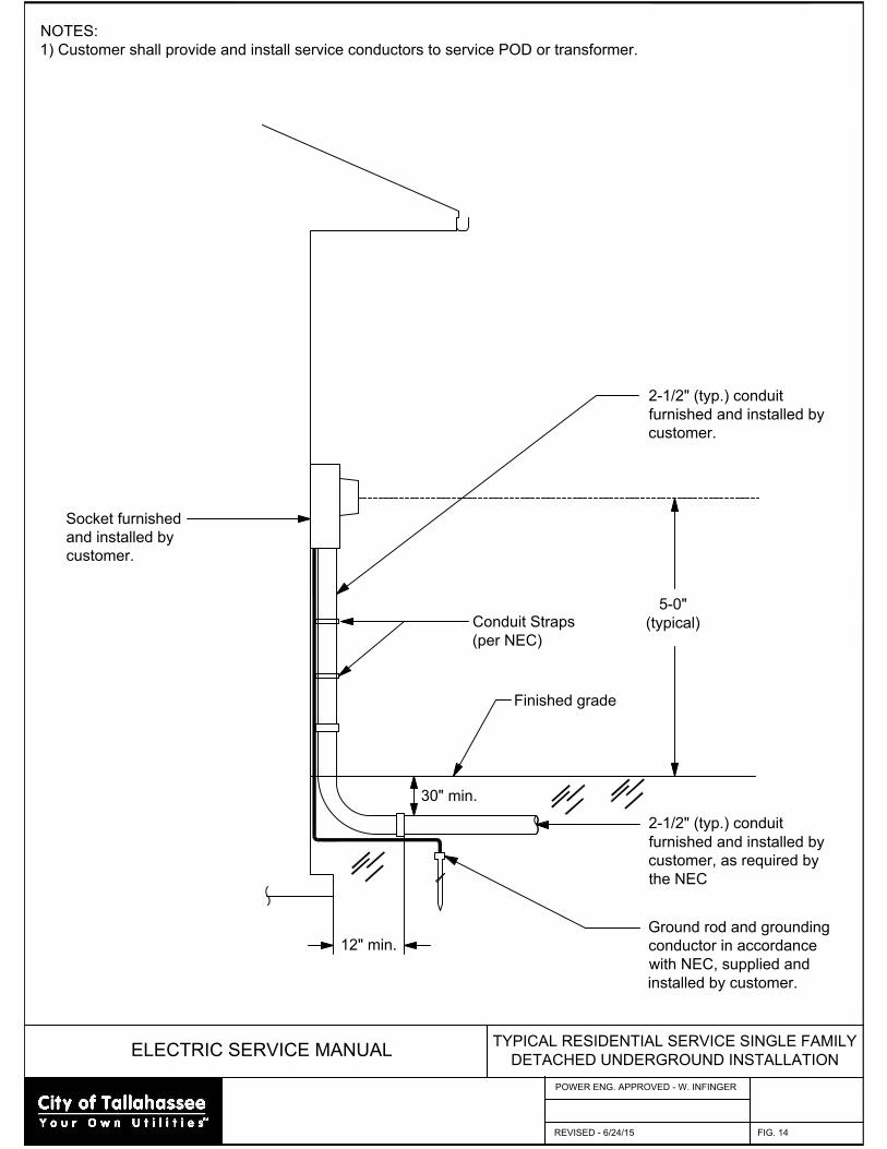
ELECTRIC SERVICE MANUAL
TYPICAL RESIDENTIAL SERVICE SINGLE FAMILY
DETACHED UNDERGROUND INSTALLATION
REVISED - 6/24/15
POWER ENG. APPROVED - W. INFINGER
FIG. 14
NOTES:
1) Customer shall provide and install service conductors to service POD or transformer.
Ground rod and grounding
conductor in accordance
with NEC, supplied and
installed by customer.
5-0"
(typical)
Socket furnished
and installed by
customer.
Finished grade
Conduit Straps
(per NEC)
30" min.
12" min.
2-1/2" (typ.) conduit
furnished and installed by
customer.
2-1/2" (typ.) conduit
furnished and installed by
customer, as required by
the NEC
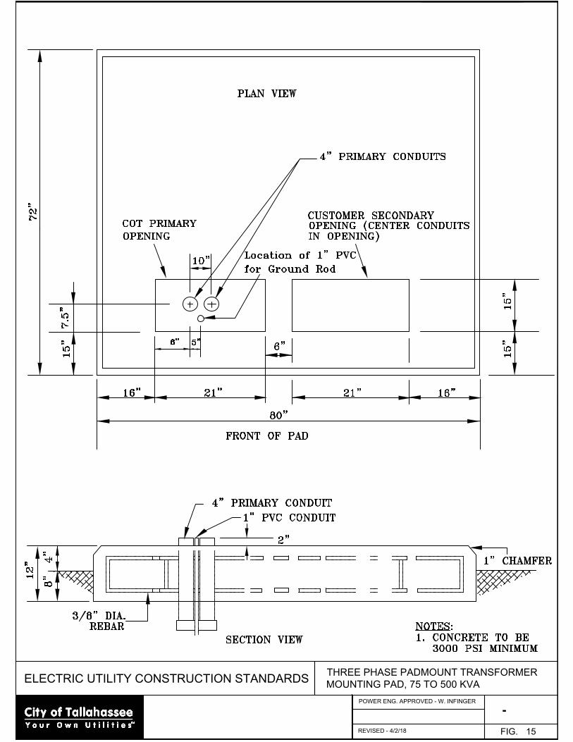
ELECTRIC UTILITY CONSTRUCTION STANDARDS
-
THREE PHASE PADMOUNT TRANSFORMER
MOUNTING PAD, 75 TO 500 KVA
FIG. 15
REVISED - 4/2/18
POWER ENG. APPROVED - W. INFINGER
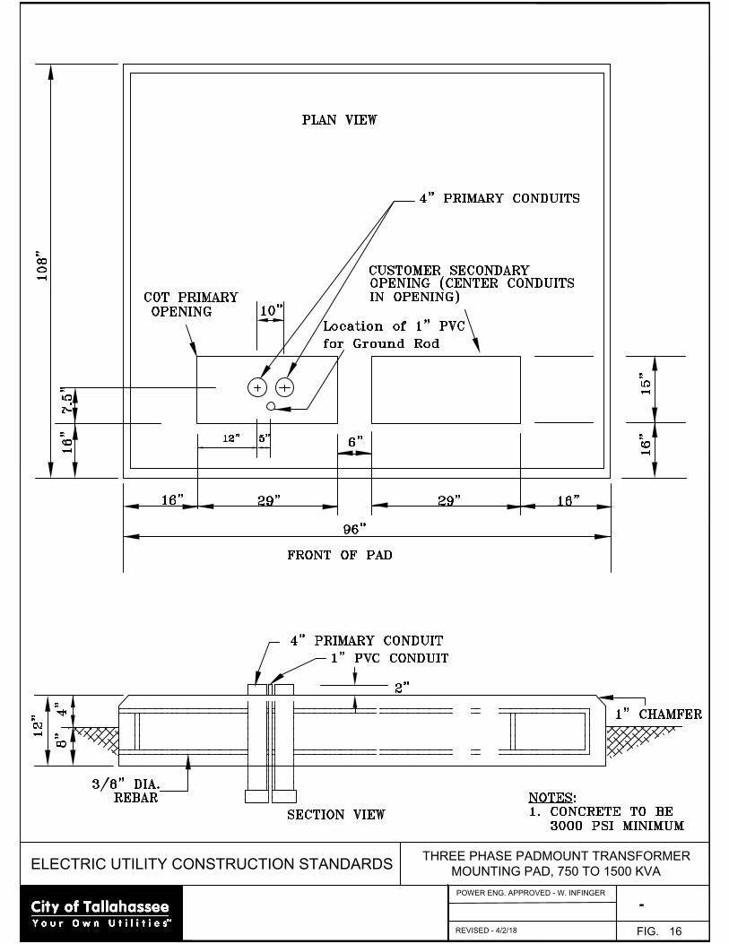
ELECTRIC UTILITY CONSTRUCTION STANDARDS
-
THREE PHASE PADMOUNT TRANSFORMER
MOUNTING PAD, 750 TO 1500 KVA
FIG. 16
POWER ENG. APPROVED - W. INFINGER
REVISED - 4/2/18

ELECTRIC UTILITY CONSTRUCTION STANDARDS
-
THREE PHASE PADMOUNT TRANSFORMER
MOUNTING PAD, 2000 TO 2500 KVA
FIG. 17
POWER ENG. APPROVED - W. INFINGER
REVISED - 4/2/18
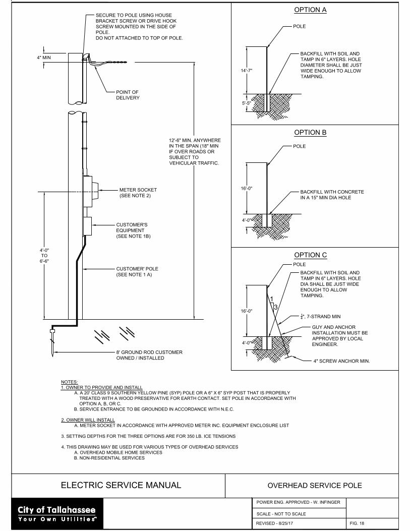
ELECTRIC SERVICE MANUAL OVERHEAD SERVICE POLE
FIG. 18
CUSTOMER' POLE
(SEE NOTE 1 A)
CUSTOMER'S
EQUIPMENT
(SEE NOTE 1B)
METER SOCKET
(SEE NOTE 2)
POINT OF
DELIVERY
4'-0"
TO
6'-6"
4" MIN
8' GROUND ROD CUSTOMER
OWNED / INSTALLED
SECURE TO POLE USING HOUSE
BRACKET SCREW OR DRIVE HOOK
SCREW MOUNTED IN THE SIDE OF
POLE.
DO NOT ATTACHED TO TOP OF POLE.
NOTES:
1. OWNER TO PROVIDE AND INSTALL
A. A 20' CLASS 9 SOUTHERN YELLOW PINE (SYP) POLE OR A 6" X 6" SYP POST THAT IS PROPERLY
TREATED WITH A WOOD PRESERVATIVE FOR EARTH CONTACT. SET POLE IN ACCORDANCE WITH
OPTION A, B, OR C.
B. SERVICE ENTRANCE TO BE GROUNDED IN ACCORDANCE WITH N.E.C.
2. OWNER WILL INSTALL
A. METER SOCKET IN ACCORDANCE WITH APPROVED METER INC. EQUIPMENT ENCLOSURE LIST
3. SETTING DEPTHS FOR THE THREE OPTIONS ARE FOR 350 LB. ICE TENSIONS
4. THIS DRAWING MAY BE USED FOR VARIOUS TYPES OF OVERHEAD SERVICES
A. OVERHEAD MOBILE HOME SERVICES
B. NON-RESIDENTIAL SERVICES
OPTION A
OPTION B
OPTION C
SCALE - NOT TO SCALE
POLE
BACKFILL WITH SOIL AND
TAMP IN 6" LAYERS. HOLE
DIAMETER SHALL BE JUST
WIDE ENOUGH TO ALLOW
TAMPING.
POLE
BACKFILL WITH CONCRETE
IN A 15" MIN DIA HOLE
14'-7"
5'-5"
16'-0"
4'-0"
POLE
BACKFILL WITH SOIL AND
TAMP IN 6" LAYERS. HOLE
DIA SHALL BE JUST WIDE
ENOUGH TO ALLOW
TAMPING.
16'-0"
4'-0"
1
3
GUY AND ANCHOR
INSTALLATION MUST BE
APPROVED BY LOCAL
ENGINEER.
1
4
", 7-STRAND MIN
4" SCREW ANCHOR MIN.
12'-6" MIN. ANYWHERE
IN THE SPAN (18" MIN
IF OVER ROADS OR
SUBJECT TO
VEHICULAR TRAFFIC.
REVISED - 8/25/17
POWER ENG. APPROVED - W. INFINGER
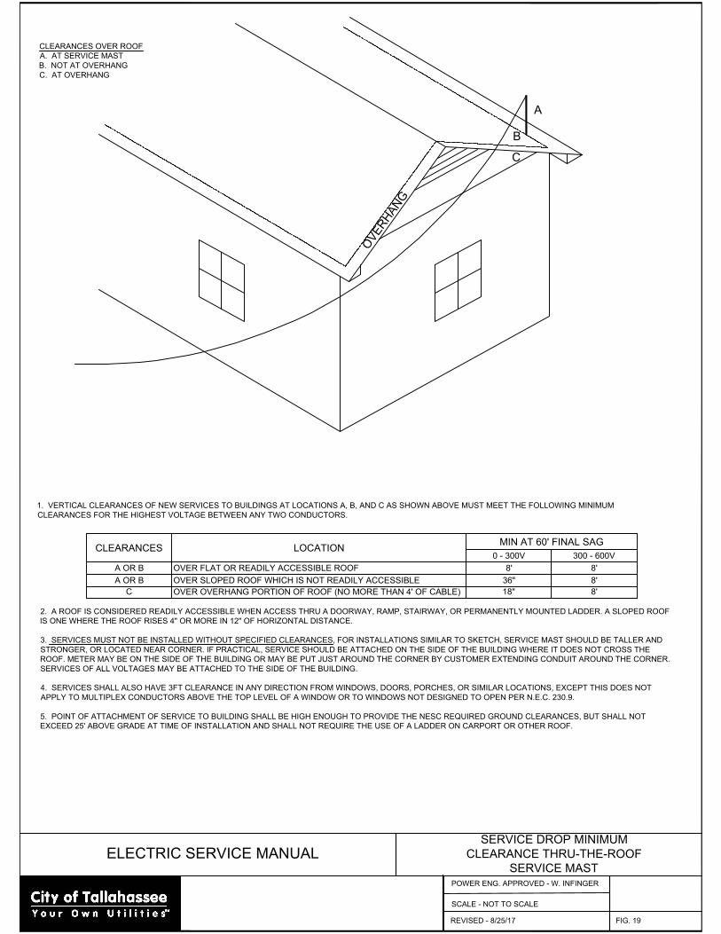
ELECTRIC SERVICE MANUAL
SERVICE DROP MINIMUM
CLEARANCE THRU-THE-ROOF
SERVICE MAST
FIG. 19
SCALE - NOT TO SCALE
1. VERTICAL CLEARANCES OF NEW SERVICES TO BUILDINGS AT LOCATIONS A, B, AND C AS SHOWN ABOVE MUST MEET THE FOLLOWING MINIMUM
CLEARANCES FOR THE HIGHEST VOLTAGE BETWEEN ANY TWO CONDUCTORS.
CLEARANCES LOCATION
MIN AT 60' FINAL SAG
0 - 300V 300 - 600V
A OR B OVER FLAT OR READILY ACCESSIBLE ROOF 8' 8'
A OR B OVER SLOPED ROOF WHICH IS NOT READILY ACCESSIBLE 36" 8'
C OVER OVERHANG PORTION OF ROOF (NO MORE THAN 4' OF CABLE) 18" 8'
2. A ROOF IS CONSIDERED READILY ACCESSIBLE WHEN ACCESS THRU A DOORWAY, RAMP, STAIRWAY, OR PERMANENTLY MOUNTED LADDER. A SLOPED ROOF
IS ONE WHERE THE ROOF RISES 4" OR MORE IN 12" OF HORIZONTAL DISTANCE.
3. SERVICES MUST NOT BE INSTALLED WITHOUT SPECIFIED CLEARANCES, FOR INSTALLATIONS SIMILAR TO SKETCH, SERVICE MAST SHOULD BE TALLER AND
STRONGER, OR LOCATED NEAR CORNER. IF PRACTICAL, SERVICE SHOULD BE ATTACHED ON THE SIDE OF THE BUILDING WHERE IT DOES NOT CROSS THE
ROOF. METER MAY BE ON THE SIDE OF THE BUILDING OR MAY BE PUT JUST AROUND THE CORNER BY CUSTOMER EXTENDING CONDUIT AROUND THE CORNER.
SERVICES OF ALL VOLTAGES MAY BE ATTACHED TO THE SIDE OF THE BUILDING.
4. SERVICES SHALL ALSO HAVE 3FT CLEARANCE IN ANY DIRECTION FROM WINDOWS, DOORS, PORCHES, OR SIMILAR LOCATIONS, EXCEPT THIS DOES NOT
APPLY TO MULTIPLEX CONDUCTORS ABOVE THE TOP LEVEL OF A WINDOW OR TO WINDOWS NOT DESIGNED TO OPEN PER N.E.C. 230.9.
5. POINT OF ATTACHMENT OF SERVICE TO BUILDING SHALL BE HIGH ENOUGH TO PROVIDE THE NESC REQUIRED GROUND CLEARANCES, BUT SHALL NOT
EXCEED 25' ABOVE GRADE AT TIME OF INSTALLATION AND SHALL NOT REQUIRE THE USE OF A LADDER ON CARPORT OR OTHER ROOF.
CLEARANCES OVER ROOF
A. AT SERVICE MAST
B. NOT AT OVERHANG
C. AT OVERHANG
A
B
C
O
V
E
R
H
A
N
G
REVISED - 8/25/17
POWER ENG. APPROVED - W. INFINGER
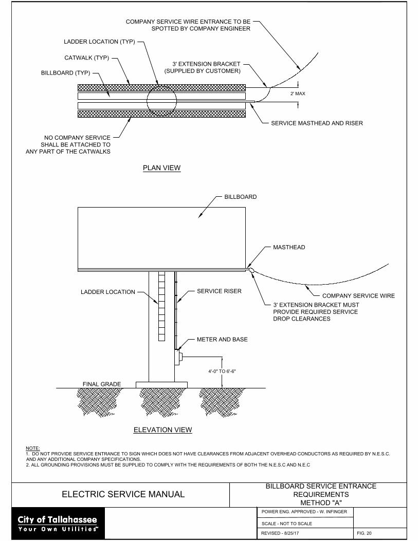
ELECTRIC SERVICE MANUAL
BILLBOARD SERVICE ENTRANCE
REQUIREMENTS
METHOD "A"
FIG. 20
SCALE - NOT TO SCALE
NOTE:
1. DO NOT PROVIDE SERVICE ENTRANCE TO SIGN WHICH DOES NOT HAVE CLEARANCES FROM ADJACENT OVERHEAD CONDUCTORS AS REQUIRED BY N.E.S.C.
AND ANY ADDITIONAL COMPANY SPECIFICATIONS.
2. ALL GROUNDING PROVISIONS MUST BE SUPPLIED TO COMPLY WITH THE REQUIREMENTS OF BOTH THE N.E.S.C AND N.E.C
4'-0" TO 6'-6"
COMPANY SERVICE WIRE
3' EXTENSION BRACKET MUST
PROVIDE REQUIRED SERVICE
DROP CLEARANCES
MASTHEAD
SERVICE RISER
LADDER LOCATION
BILLBOARD
METER AND BASE
FINAL GRADE
LADDER LOCATION (TYP)
CATWALK (TYP)
BILLBOARD (TYP)
SERVICE MASTHEAD AND RISER
3' EXTENSION BRACKET
(SUPPLIED BY CUSTOMER)
NO COMPANY SERVICE
SHALL BE ATTACHED TO
ANY PART OF THE CATWALKS
2' MAX
COMPANY SERVICE WIRE ENTRANCE TO BE
SPOTTED BY COMPANY ENGINEER
ELEVATION VIEW
PLAN VIEW
REVISED - 8/25/17
POWER ENG. APPROVED - W. INFINGER
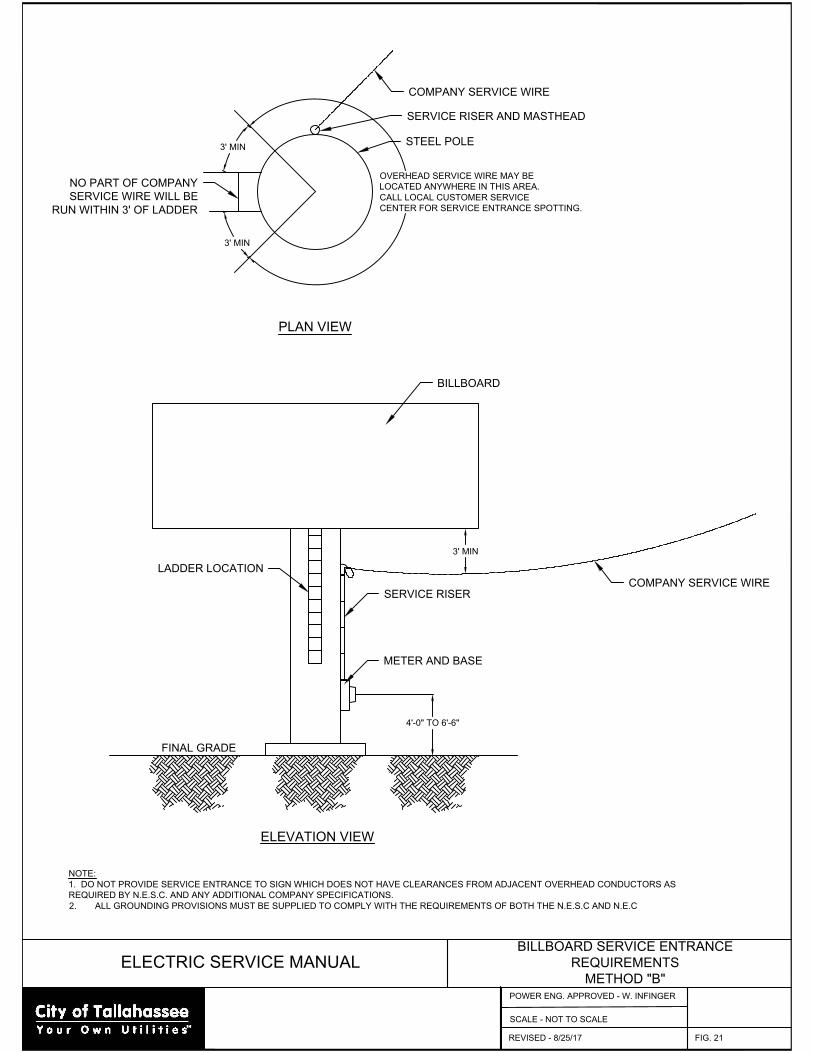
ELECTRIC SERVICE MANUAL
BILLBOARD SERVICE ENTRANCE
REQUIREMENTS
METHOD "B"
FIG. 21
SCALE - NOT TO SCALE
NOTE:
1. DO NOT PROVIDE SERVICE ENTRANCE TO SIGN WHICH DOES NOT HAVE CLEARANCES FROM ADJACENT OVERHEAD CONDUCTORS AS
REQUIRED BY N.E.S.C. AND ANY ADDITIONAL COMPANY SPECIFICATIONS.
2. ALL GROUNDING PROVISIONS MUST BE SUPPLIED TO COMPLY WITH THE REQUIREMENTS OF BOTH THE N.E.S.C AND N.E.C
4'-0" TO 6'-6"
COMPANY SERVICE WIRE
SERVICE RISER
LADDER LOCATION
BILLBOARD
METER AND BASE
FINAL GRADE
ELEVATION VIEW
PLAN VIEW
3' MIN
3' MIN
3' MIN
OVERHEAD SERVICE WIRE MAY BE
LOCATED ANYWHERE IN THIS AREA.
CALL LOCAL CUSTOMER SERVICE
CENTER FOR SERVICE ENTRANCE SPOTTING.
NO PART OF COMPANY
SERVICE WIRE WILL BE
RUN WITHIN 3' OF LADDER
COMPANY SERVICE WIRE
SERVICE RISER AND MASTHEAD
STEEL POLE
REVISED - 8/25/17
POWER ENG. APPROVED - W. INFINGER
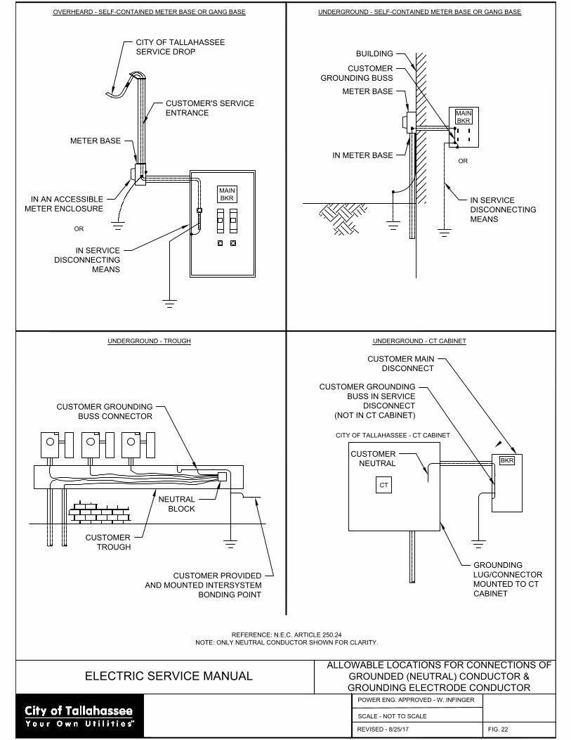
ELECTRIC SERVICE MANUAL
ALLOWABLE LOCATIONS FOR CONNECTIONS OF
GROUNDED (NEUTRAL) CONDUCTOR &
GROUNDING ELECTRODE CONDUCTOR
FIG. 22
REFERENCE: N.E.C. ARTICLE 250.24
NOTE: ONLY NEUTRAL CONDUCTOR SHOWN FOR CLARITY.
UNDERGROUND - TROUGH
OVERHEARD - SELF-CONTAINED METER BASE OR GANG BASE UNDERGROUND - SELF-CONTAINED METER BASE OR GANG BASE
UNDERGROUND - CT CABINET
CITY OF TALLAHASSEE - CT CABINET
BKR
CUSTOMER MAIN
DISCONNECT
CUSTOMER GROUNDING
BUSS IN SERVICE
DISCONNECT
(NOT IN CT CABINET)
CT
GROUNDING
LUG/CONNECTOR
MOUNTED TO CT
CABINET
CUSTOMER
NEUTRAL
CUSTOMER PROVIDED
AND MOUNTED INTERSYSTEM
BONDING POINT
CUSTOMER GROUNDING
BUSS CONNECTOR
CUSTOMER
TROUGH
NEUTRAL
BLOCK
MAIN
BKR
IN SERVICE
DISCONNECTING
MEANS
OR
CUSTOMER
GROUNDING BUSS
METER BASE
BUILDING
IN METER BASE
MAIN
BKR
CITY OF TALLAHASSEE
SERVICE DROP
CUSTOMER'S SERVICE
ENTRANCE
METER BASE
IN AN ACCESSIBLE
METER ENCLOSURE
OR
IN SERVICE
DISCONNECTING
MEANS
REVISED - 8/25/17
POWER ENG. APPROVED - W. INFINGER
SCALE - NOT TO SCALE
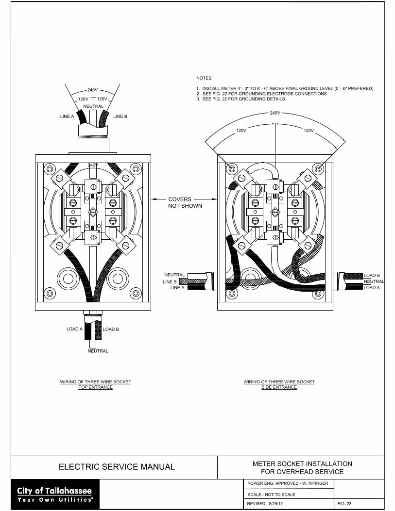
ELECTRIC SERVICE MANUAL
METER SOCKET INSTALLATION
FOR OVERHEAD SERVICE
FIG. 23
SCALE - NOT TO SCALE
240V
240V
120V120V
120V120V
240V
WIRING OF THREE WIRE SOCKET
TOP ENTRANCE
WIRING OF THREE WIRE SOCKET
SIDE ENTRANCE
LINE A LINE B
NEUTRAL
COVERS
NOT SHOWN
NOTES:
1. INSTALL METER 4' - 0" TO 6' - 6" ABOVE FINAL GROUND LEVEL (5' - 6" PREFERED).
2. SEE FIG. 22 FOR GROUNDING ELECTRODE CONNECTIONS
3. SEE FIG. 22 FOR GROUNDING DETAILS
NEUTRAL
LINE B
LINE A
NEUTRAL
LOAD B
LOAD A
NEUTRAL
LOAD B
LOAD A
REVISED - 8/25/17
POWER ENG. APPROVED - W. INFINGER

ELECTRIC SERVICE MANUAL
TYPICAL SELF-CONTAINED
SINGLE-PHASE METER BASES
FIG. 24
SCALE - NOT TO SCALE
100 AMP, 4 LUG, 120/240 VOLT
200 AMP, 4 LUG, 120/240 VOLT
120V
120V
240V
CUSTOMER OWNED
CONDUCTORS
CUSTOMER OWNED
CONDUCTORS
NOTES:
1. 2/0 AWC IS MAXIMUM CONDUCTOR SIZE
CUSTOMER OWNED
CONDUCTORS
CUSTOMER OWNED
CONDUCTORS
NOTES:
1. 4/0 KCMIL IS MAX. CONDUCTOR SIZE FOR
CUSTOMER OWNED METER BASES FOR 350
KCMIL OR LARGER CONDUCTORS USE 4" LONG
PIN CONNECTOR.
2. BASE HAS THREE 3" IN BOTTOM KNOCKOUTS
3. WHEN USING THIS BASE FOR UNDERGROUND
SERVICES, PUSH THE SERVICE WIRES DOWN
INTO THE RISER/BENDS TO ALLOW FOR
CONDUCTOR SLACK SHOULD THE TRENCH
BACKFILL CAUSE CONDUCTOR TENSION ON THE
METER BASE LUGS.
4. NO CUSTOMER CONDUCTORS MAY ENTER THE
METER BASE FROM THE RIGHT HAND SIDE TO
PREVENT CROSSING OF COMPANY CONDUCTORS
BY CUSTOMER CONDUCTORS.
5. SEE FIG. 22 FOR GROUNDING DETAILS.
120V
120V
240V
REVISED - 8/25/17
POWER ENG. APPROVED - W. INFINGER
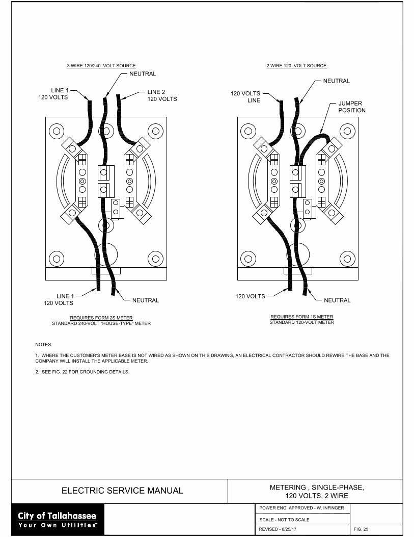
ELECTRIC SERVICE MANUAL
METERING , SINGLE-PHASE,
120 VOLTS, 2 WIRE
FIG. 25
SCALE - NOT TO SCALE
REQUIRES FORM 2S METER
STANDARD 240-VOLT "HOUSE-TYPE" METER
REQUIRES FORM 1S METER
STANDARD 120-VOLT METER
3 WIRE 120/240 VOLT SOURCE 2 WIRE 120 VOLT SOURCE
NOTES:
1. WHERE THE CUSTOMER'S METER BASE IS NOT WIRED AS SHOWN ON THIS DRAWING, AN ELECTRICAL CONTRACTOR SHOULD REWIRE THE BASE AND THE
COMPANY WILL INSTALL THE APPLICABLE METER.
2. SEE FIG. 22 FOR GROUNDING DETAILS.
LINE 1
120 VOLTS
NEUTRAL
LINE 2
120 VOLTS
LINE 1
120 VOLTS
NEUTRAL
120 VOLTS
NEUTRAL
NEUTRAL
120 VOLTS
LINE
JUMPER
POSITION
REVISED - 8/25/17
POWER ENG. APPROVED - W. INFINGER
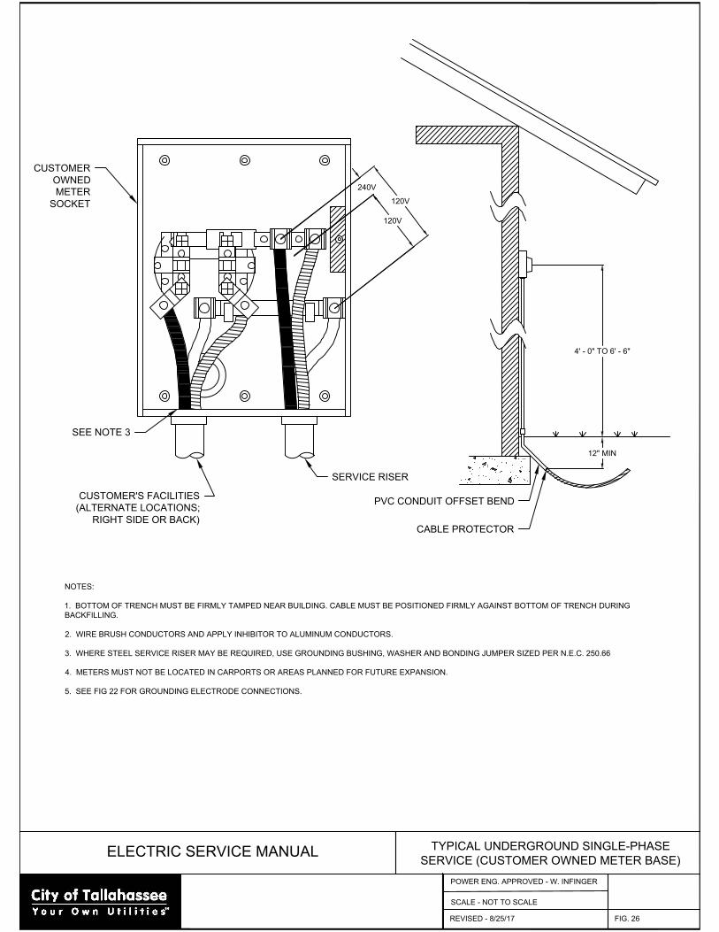
ELECTRIC SERVICE MANUAL
TYPICAL UNDERGROUND SINGLE-PHASE
SERVICE (CUSTOMER OWNED METER BASE)
FIG. 26
SCALE - NOT TO SCALE
4' - 0" TO 6' - 6"
12" MIN
PVC CONDUIT OFFSET BEND
CABLE PROTECTOR
NOTES:
1. BOTTOM OF TRENCH MUST BE FIRMLY TAMPED NEAR BUILDING. CABLE MUST BE POSITIONED FIRMLY AGAINST BOTTOM OF TRENCH DURING
BACKFILLING.
2. WIRE BRUSH CONDUCTORS AND APPLY INHIBITOR TO ALUMINUM CONDUCTORS.
3. WHERE STEEL SERVICE RISER MAY BE REQUIRED, USE GROUNDING BUSHING, WASHER AND BONDING JUMPER SIZED PER N.E.C. 250.66
4. METERS MUST NOT BE LOCATED IN CARPORTS OR AREAS PLANNED FOR FUTURE EXPANSION.
5. SEE FIG 22 FOR GROUNDING ELECTRODE CONNECTIONS.
120V
240V
120V
CUSTOMER'S FACILITIES
(ALTERNATE LOCATIONS;
RIGHT SIDE OR BACK)
SERVICE RISER
SEE NOTE 3
CUSTOMER
OWNED
METER
SOCKET
REVISED - 8/25/17
POWER ENG. APPROVED - W. INFINGER

ELECTRIC SERVICE MANUAL
GROUP METERING INSTALLATION
(HORIZONTAL TYPE)
FIG. 27
SCALE - NOT TO SCALE
4' - 0" TO 6' - 6"
NOTES:
1. U.L. LISTED GANGED METER SOCKETS TO BE FURNISHED AND OWNED BY CUSTOMER. ELECTRICAL CONTRACTOR TO INSTALL ON OUTSIDE BUILDING
WALL AND TO BOND TO NEUTRAL.
2. SEE FIG 29 IF MAIN BREAKER IS REQUIRED.
3. IF ANY OF THE INDIVIDUAL SERVICES REQUIRE A METER SOCKET GREATER THAN 200 AMP CAPACITY THEN A GANGED PANEL OF GREATER AMPACITY
MUST BE USED.
4. LABELING OF EACH METER ENCLOSURE SHALL MEET THE REQUIREMENTS OF FIGURE 3.
5. SEE FIG 22 FOR GROUNDING DETAILS.
A B C D E F
SEE NOTE 4
FINAL GRADE
REVISED - 8/25/17
POWER ENG. APPROVED - W. INFINGER
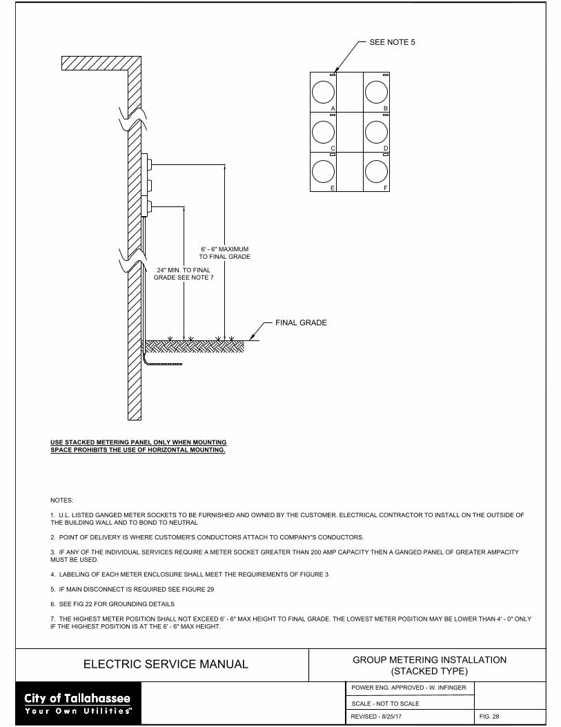
ELECTRIC SERVICE MANUAL
GROUP METERING INSTALLATION
(STACKED TYPE)
FIG. 28
SCALE - NOT TO SCALE
24" MIN. TO FINAL
GRADE SEE NOTE 7
NOTES:
1. U.L. LISTED GANGED METER SOCKETS TO BE FURNISHED AND OWNED BY THE CUSTOMER. ELECTRICAL CONTRACTOR TO INSTALL ON THE OUTSIDE OF
THE BUILDING WALL AND TO BOND TO NEUTRAL
2. POINT OF DELIVERY IS WHERE CUSTOMER'S CONDUCTORS ATTACH TO COMPANY'S CONDUCTORS.
3. IF ANY OF THE INDIVIDUAL SERVICES REQUIRE A METER SOCKET GREATER THAN 200 AMP CAPACITY THEN A GANGED PANEL OF GREATER AMPACITY
MUST BE USED.
4. LABELING OF EACH METER ENCLOSURE SHALL MEET THE REQUIREMENTS OF FIGURE 3
5. IF MAIN DISCONNECT IS REQUIRED SEE FIGURE 29
6. SEE FIG 22 FOR GROUNDING DETAILS
7. THE HIGHEST METER POSITION SHALL NOT EXCEED 6' - 6" MAX HEIGHT TO FINAL GRADE. THE LOWEST METER POSITION MAY BE LOWER THAN 4' - 0" ONLY
IF THE HIGHEST POSITION IS AT THE 6' - 6" MAX HEIGHT.
A
SEE NOTE 5
C
E
B
D
F
6' - 6" MAXIMUM
TO FINAL GRADE
FINAL GRADE
USE STACKED METERING PANEL ONLY WHEN MOUNTING
SPACE PROHIBITS THE USE OF HORIZONTAL MOUNTING.
REVISED - 8/25/17
POWER ENG. APPROVED - W. INFINGER

ELECTRIC SERVICE MANUAL
GROUP METERING INSTALLATION
(MAIN BREAKER)
FIG. 29
SCALE - NOT TO SCALE
NOTES:
1. U.L. LISTED METER CENTER TO BE FURNISHED AND OWNED BY THE CUSTOMER. ELECTRICAL CONTRACTOR TO INSTALL ON THE OUTSIDE OF THE
BUILDING WALL AND TO BOND TO NEUTRAL.
2. LABEL EACH SOCKET COVER AS SHOWN IN FIGURE 3
3. SEE FIG 22 FOR GROUNDING DETAILS
METER CENTER
(CUSTOMER OWNED)
CUSTOMER'S
MAIN BREAKER
SEE NOTE 3
OPTIONAL TERMINAL
BLOCKS. SEE NOTE 4
REVISED - 8/25/17
POWER ENG. APPROVED - W. INFINGER
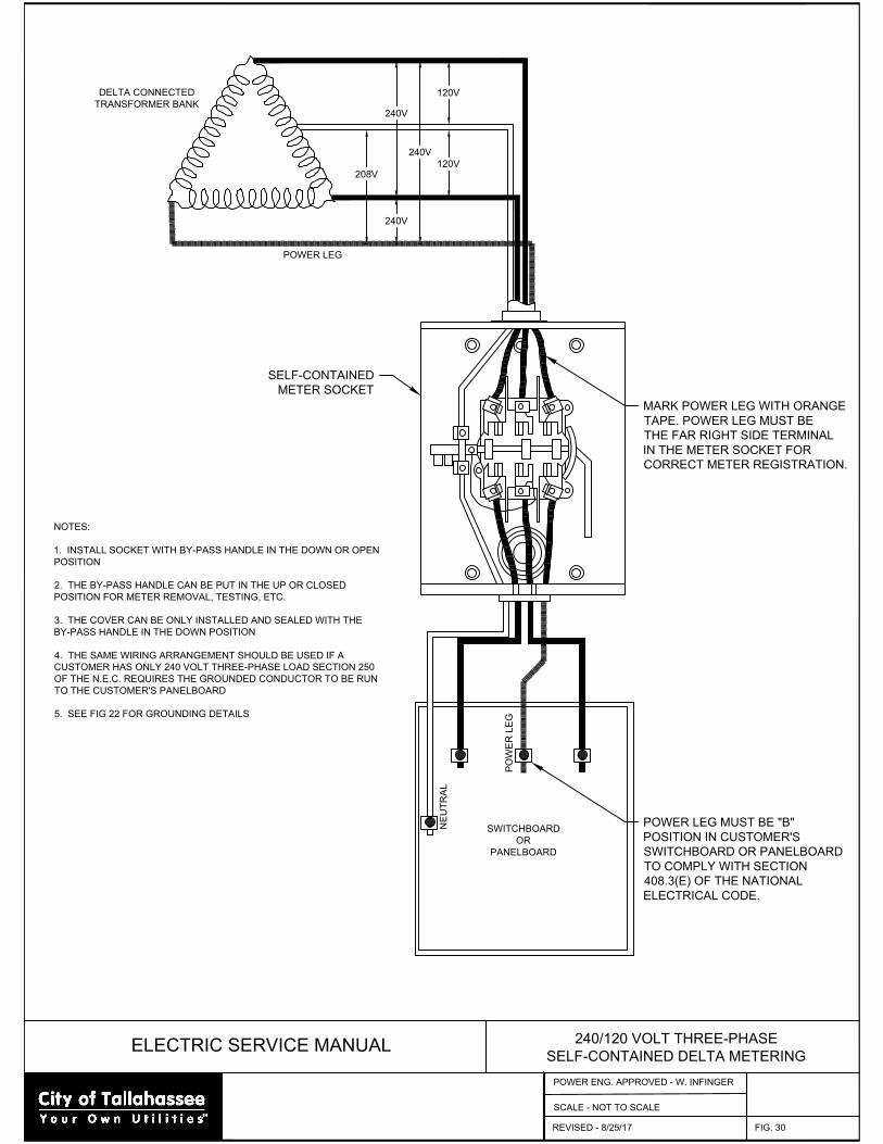
ELECTRIC SERVICE MANUAL
240/120 VOLT THREE-PHASE
SELF-CONTAINED DELTA METERING
FIG. 30
SCALE - NOT TO SCALE
NOTES:
1. INSTALL SOCKET WITH BY-PASS HANDLE IN THE DOWN OR OPEN
POSITION
2. THE BY-PASS HANDLE CAN BE PUT IN THE UP OR CLOSED
POSITION FOR METER REMOVAL, TESTING, ETC.
3. THE COVER CAN BE ONLY INSTALLED AND SEALED WITH THE
BY-PASS HANDLE IN THE DOWN POSITION
4. THE SAME WIRING ARRANGEMENT SHOULD BE USED IF A
CUSTOMER HAS ONLY 240 VOLT THREE-PHASE LOAD SECTION 250
OF THE N.E.C. REQUIRES THE GROUNDED CONDUCTOR TO BE RUN
TO THE CUSTOMER'S PANELBOARD
5. SEE FIG 22 FOR GROUNDING DETAILS
SWITCHBOARD
OR
PANELBOARD
PO
WE
R L
EG
NE
UT
RA
L
POWER LEG MUST BE "B"
POSITION IN CUSTOMER'S
SWITCHBOARD OR PANELBOARD
TO COMPLY WITH SECTION
408.3(E) OF THE NATIONAL
ELECTRICAL CODE.
MARK POWER LEG WITH ORANGE
TAPE. POWER LEG MUST BE
THE FAR RIGHT SIDE TERMINAL
IN THE METER SOCKET FOR
CORRECT METER REGISTRATION.
SELF-CONTAINED
METER SOCKET
POWER LEG
DELTA CONNECTED
TRANSFORMER BANK
120V
120V
240V
240V
240V
208V
REVISED - 8/25/17
POWER ENG. APPROVED - W. INFINGER
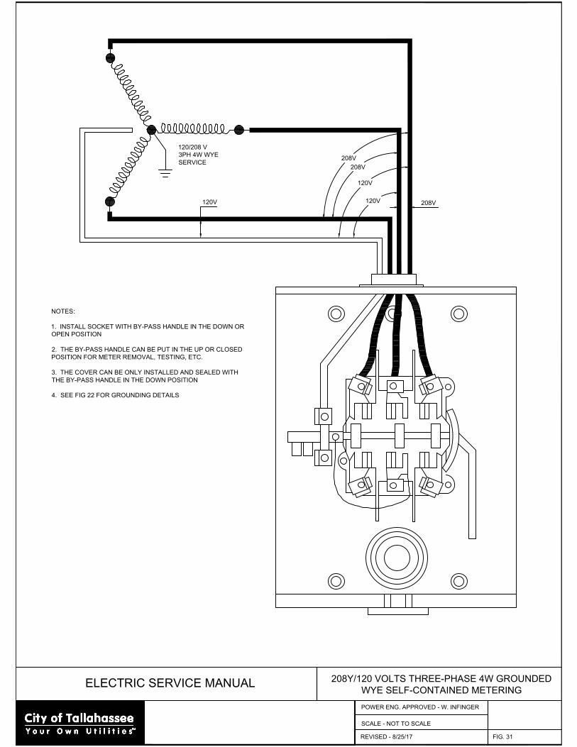
ELECTRIC SERVICE MANUAL
208Y/120 VOLTS THREE-PHASE 4W GROUNDED
WYE SELF-CONTAINED METERING
FIG. 31
SCALE - NOT TO SCALE
NOTES:
1. INSTALL SOCKET WITH BY-PASS HANDLE IN THE DOWN OR
OPEN POSITION
2. THE BY-PASS HANDLE CAN BE PUT IN THE UP OR CLOSED
POSITION FOR METER REMOVAL, TESTING, ETC.
3. THE COVER CAN BE ONLY INSTALLED AND SEALED WITH
THE BY-PASS HANDLE IN THE DOWN POSITION
4. SEE FIG 22 FOR GROUNDING DETAILS
120V
120V
208V
208V
208V
120V
120/208 V
3PH 4W WYE
SERVICE
REVISED - 8/25/17
POWER ENG. APPROVED - W. INFINGER
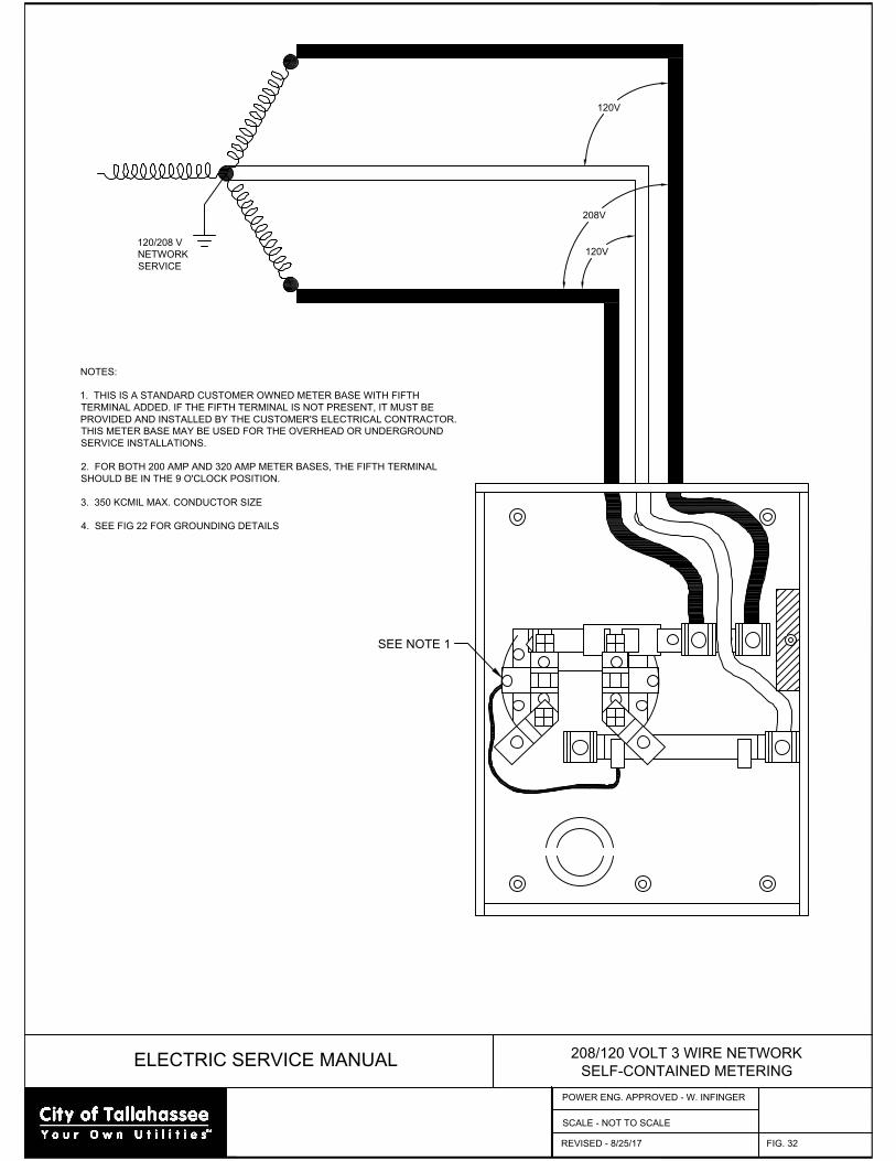
ELECTRIC SERVICE MANUAL
208/120 VOLT 3 WIRE NETWORK
SELF-CONTAINED METERING
FIG. 32
SCALE - NOT TO SCALE
120V
120V
208V
120/208 V
NETWORK
SERVICE
SEE NOTE 1
NOTES:
1. THIS IS A STANDARD CUSTOMER OWNED METER BASE WITH FIFTH
TERMINAL ADDED. IF THE FIFTH TERMINAL IS NOT PRESENT, IT MUST BE
PROVIDED AND INSTALLED BY THE CUSTOMER'S ELECTRICAL CONTRACTOR.
THIS METER BASE MAY BE USED FOR THE OVERHEAD OR UNDERGROUND
SERVICE INSTALLATIONS.
2. FOR BOTH 200 AMP AND 320 AMP METER BASES, THE FIFTH TERMINAL
SHOULD BE IN THE 9 O'CLOCK POSITION.
3. 350 KCMIL MAX. CONDUCTOR SIZE
4. SEE FIG 22 FOR GROUNDING DETAILS
REVISED - 8/25/17
POWER ENG. APPROVED - W. INFINGER
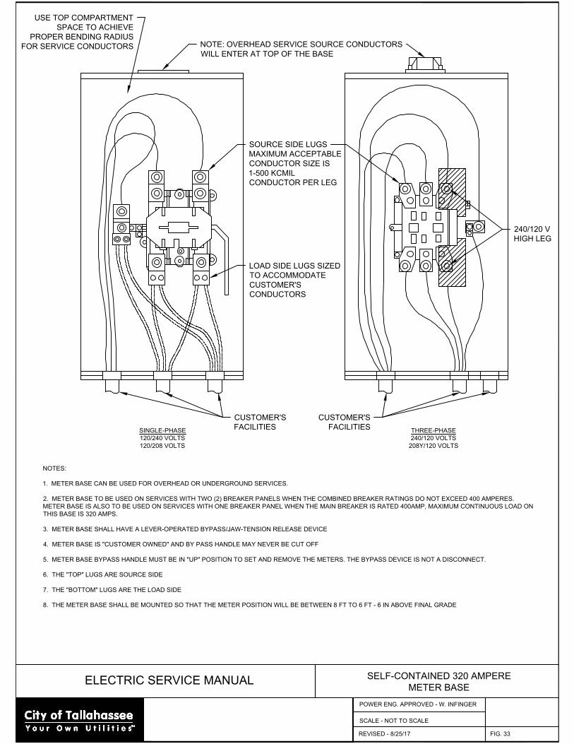
ELECTRIC SERVICE MANUAL
SELF-CONTAINED 320 AMPERE
METER BASE
FIG. 33
SCALE - NOT TO SCALE
NOTES:
1. METER BASE CAN BE USED FOR OVERHEAD OR UNDERGROUND SERVICES.
2. METER BASE TO BE USED ON SERVICES WITH TWO (2) BREAKER PANELS WHEN THE COMBINED BREAKER RATINGS DO NOT EXCEED 400 AMPERES.
METER BASE IS ALSO TO BE USED ON SERVICES WITH ONE BREAKER PANEL WHEN THE MAIN BREAKER IS RATED 400AMP, MAXIMUM CONTINUOUS LOAD ON
THIS BASE IS 320 AMPS.
3. METER BASE SHALL HAVE A LEVER-OPERATED BYPASS/JAW-TENSION RELEASE DEVICE
4. METER BASE IS "CUSTOMER OWNED" AND BY PASS HANDLE MAY NEVER BE CUT OFF
5. METER BASE BYPASS HANDLE MUST BE IN "UP" POSITION TO SET AND REMOVE THE METERS. THE BYPASS DEVICE IS NOT A DISCONNECT.
6. THE "TOP" LUGS ARE SOURCE SIDE
7. THE "BOTTOM" LUGS ARE THE LOAD SIDE
8. THE METER BASE SHALL BE MOUNTED SO THAT THE METER POSITION WILL BE BETWEEN 8 FT TO 6 FT - 6 IN ABOVE FINAL GRADE
SINGLE-PHASE
120/240 VOLTS
120/208 VOLTS
THREE-PHASE
240/120 VOLTS
208Y/120 VOLTS
240/120 V
HIGH LEG
CUSTOMER'S
FACILITIES
CUSTOMER'S
FACILITIES
SOURCE SIDE LUGS
MAXIMUM ACCEPTABLE
CONDUCTOR SIZE IS
1-500 KCMIL
CONDUCTOR PER LEG
USE TOP COMPARTMENT
SPACE TO ACHIEVE
PROPER BENDING RADIUS
FOR SERVICE CONDUCTORS
LOAD SIDE LUGS SIZED
TO ACCOMMODATE
CUSTOMER'S
CONDUCTORS
NOTE: OVERHEAD SERVICE SOURCE CONDUCTORS
WILL ENTER AT TOP OF THE BASE
REVISED - 8/25/17
POWER ENG. APPROVED - W. INFINGER
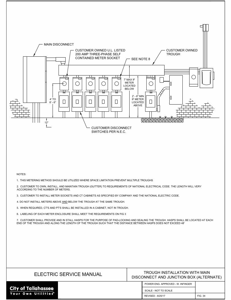
ELECTRIC SERVICE MANUAL
TROUGH INSTALLATION WITH MAIN
DISCONNECT AND JUNCTION BOX (ALTERNATE)
FIG. 34
SCALE - NOT TO SCALE
NOTES:
1. THIS METERING METHOD SHOULD BE UTILIZED WHERE SPACE LIMITATION PREVENT MULTIPLE TROUGHS
2. CUSTOMER TO OWN, INSTALL, AND MAINTAIN TROUGH (GUTTER) TO REQUIREMENTS OF NATIONAL ELECTRICAL CODE. THE LENGTH WILL VERY
ACCORDING TO THE NUMBER OF METERS.
3. CUSTOMER TO INSTALL METER SOCKETS AND CT CABINETS AS SPECIFIED BY COMPANY AND THE NATIONAL ELECTRIC CODE.
4. DO NOT INSTALL METERS ABOVE AND BELOW THE TROUGH AT THE SAME TROUGH.
5. WHEN REQUIRED, CT'S AND PT'S SHALL BE INSTALLED IN A CABINET, NOT IN TROUGH.
6. LABELING OF EACH METER ENCLOSURE SHALL MEET THE REQUIREMENTS ON FIG 3
7. CUSTOMER SHALL PROVIDE AND IN STALL HASPS FOR THE PURPOSE OF PAD-LOCKING AND SEALING THE TROUGH. HASPS SHALL BE LOCATED AT EACH
END OF THE TROUGH AND ALONG THE LENGTH OF THE TROUGH SUCH THAT THE DISTANCE BETWEEN HASPS DOES NOT EXCEED 48'
12"
4' TO
6' - 6"
7' MAX IF
METER
LOCATED
BELOW
2' - 6" MIN
IF METER
LOCATED
ABOVE
MAIN DISCONNECT
CUSTOMER OWNED U.L. LISTED
200 AMP THREE-PHASE SELF
CONTAINED METER SOCKET
SEE NOTE 8
CUSTOMER OWNED
TROUGH
CUSTOMER DISCONNECT
SWITCHES PER N.E.C.
REVISED - 8/25/17
POWER ENG. APPROVED - W. INFINGER
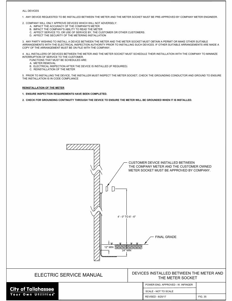
ELECTRIC SERVICE MANUAL
DEVICES INSTALLED BETWEEN THE METER AND
THE METER SOCKET
FIG. 35
SCALE - NOT TO SCALE
ALL DEVICES
1. ANY DEVICE REQUESTED TO BE INSTALLED BETWEEN THE METER AND THE METER SOCKET MUST BE PRE-APPROVED BY COMPANY METER ENGINEER.
2. COMPANY WILL ONLY APPROVE DEVICES WHICH WILL NOT ADVERSELY:
A. IMPACT THE ACCURACY OF THE COMPANY'S METER
B. IMPACT THE COMPANY'S ABILITY TO READ THE METER
C. AFFECT SERVICE TO, OR USE OF SERVICE BY, THE CUSTOMER OR OTHER CUSTOMERS.
D. AFFECT THE SECURITY OF THE METERING INSTALLATION
3. ANY PARTY WISHING TO INSTALL A DEVICE BETWEEN THE METER AND THE METER SOCKET MUST OBTAIN A PERMIT OR MAKE OTHER SUITABLE
ARRANGEMENTS WITH THE ELECTRICAL INSPECTION AUTHORITY PRIOR TO INSTALLING SUCH DEVICES. IF OTHER SUITABLE ARRANGEMENTS ARE MADE A
COPY OF THE ARRANGEMENT MUST BE ON FILE WITH THE COMPANY.
4. ALL INSTALLERS OF DEVICES BETWEEN THE METER AND THE METER SOCKET MUST SCHEDULE THEIR INSTALLATION WITH THE COMPANY TO MINIMIZE
INTERRUPTION OF SERVICE TO THE CUSTOMER.
FUNCTIONS THAT MUST BE SCHEDULED ARE:
A. METER REMOVAL
B. ELECTRICAL INSPECTION AFTER THE DEVICE IS INSTALLED (IF REQUIRED)
C. REINSTALLATION OF THE METER
5. PRIOR TO INSTALLING THE DEVICE, THE INSTALLER MUST INSPECT THE METER SOCKET, CHECK THE GROUNDING CONDUCTOR AND GROUND TO ENSURE
THE INSTALLATION IS IN CODE COMPLIANCE
REINSTALLATION OF THE METER
1. ENSURE INSPECTION REQUIREMENTS HAVE BEEN COMPLETED.
2. CHECK FOR GROUNDING CONTINUITY THROUGH THE DEVICE TO ENSURE THE METER WILL BE GROUNDED WHEN IT IS INSTALLED.
4' - 0" TO 6' - 6"
24" MIN
12" MIN
FINAL GRADE
CUSTOMER DEVICE INSTALLED BETWEEN
THE COMPANY METER AND THE CUSTOMER OWNED
METER SOCKET MUST BE APPROVED BY COMPANY.
REVISED - 8/25/17
POWER ENG. APPROVED - W. INFINGER

Page 89
13. APPENDIX D – OVERHEAD AREA LIGHTS CUSTOMER CONTRACT
OVERHEAD AREA LIGHTS – CUSTOMER CONTRACT (Revised 10/13/20)
A. Definition Area lights are defined as private out-door lights available for lighting yards, driveways, walkways and other areas. They are available inside the City’s Service territory and must be located in areas that are easily and economically accessible to City equipment and personnel for construction and maintenance.
B. General Policies
1. Area lights will be installed by City personnel on City or Joint User poles only. 2. Area lights shall not be installed until the applicable release forms have been signed. 3. Area light locations must be approved by a City service representative and accessible
through the requesting customer’s property by a E&G bucket truck. 4. Customers are responsible for locating underground utilities on their property. (e.g.
sprinkler systems, water lines, sewer lines, etc.) 5. Tree trimming is the responsibility of the customer. The City may do minor trimming as
deemed necessary by an E&G representative. 6. When new poles are installed as requested, Customer agrees to pay the monthly fee for the
use of these facilities for a minimum of five (5) years from the date installation is completed.
C. Payment for New Construction
When construction of new facilities is needed (e.g. installing new poles/wire), payment must be made at the Renaissance Building located at 435 N. Macomb St. If the customer does not already have an account with the City a customer service representative will assist them in establishing one. After this process, an E&G engineer will be notified to begin the installation procedures.
D. Administrative Fees In addition to the monthly charges for area lights there is a one-time administrative fee as
follows: 1. $25.00 per account when activating an existing area light under the same account name. 2. $35.00 per account when installing a new area light on an existing pole and/or for area
lights that require setting a new pole. 3. There is no fee for upgrading an existing area light under the same account name when
upgrading requires only replacing the light fixture.
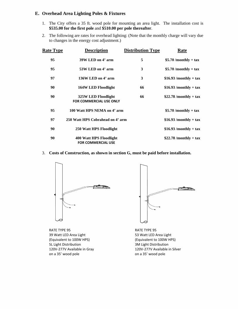
E. Overhead Area Lighting Poles & Fixtures
1. The City offers a 35 ft. wood pole for mounting an area light. The installation cost is $535.00 for the first pole and $510.00 per pole thereafter.
2. The following are rates for overhead lighting: (Note that the monthly charge will vary due to changes in the energy cost adjustment.)
Rate Type Description Distribution Type Rate
95 39W LED on 4’ arm 5 $5.70 /monthly + tax
95 53W LED on 4’ arm 3 $5.70 /monthly + tax
97 136W LED on 4’ arm 3 $16.93 /monthly + tax
90 164W LED Floodlight 66 $16.93 /monthly + tax
90 325W LED Floodlight 66 $22.78 /monthly + tax FOR COMMERCIAL USE ONLY
95 100 Watt HPS NEMA on 4’ arm $5.70 /monthly + tax
97 250 Watt HPS Cobrahead on 4’ arm $16.93 /monthly + tax
90 250 Watt HPS Floodlight $16.93 /monthly + tax
90 400 Watt HPS Floodlight $22.78 /monthly + tax FOR COMMERCIAL USE
3. Costs of Construction, as shown in section G, must be paid before installation.
RATE TYPE 95 RATE TYPE 95 39 Watt LED Area Light 53 Watt LED Area Light (Equivalent to 100W HPS) (Equivalent to 100W HPS) 5L Light Distribution 3M Light Distribution 120V-277V Available in Gray 120V-277V Available in Silver on a 35’ wood pole on a 35’ wood pole
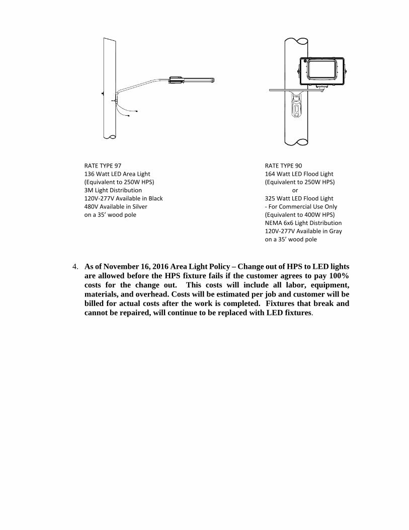
RATE TYPE 97 RATE TYPE 90 136 Watt LED Area Light 164 Watt LED Flood Light (Equivalent to 250W HPS) (Equivalent to 250W HPS) 3M Light Distribution or 120V-277V Available in Black 325 Watt LED Flood Light 480V Available in Silver - For Commercial Use Only on a 35’ wood pole (Equivalent to 400W HPS) NEMA 6x6 Light Distribution 120V-277V Available in Gray on a 35’ wood pole
4. As of November 16, 2016 Area Light Policy – Change out of HPS to LED lights are allowed before the HPS fixture fails if the customer agrees to pay 100% costs for the change out. This costs will include all labor, equipment, materials, and overhead. Costs will be estimated per job and customer will be billed for actual costs after the work is completed. Fixtures that break and cannot be repaired, will continue to be replaced with LED fixtures.
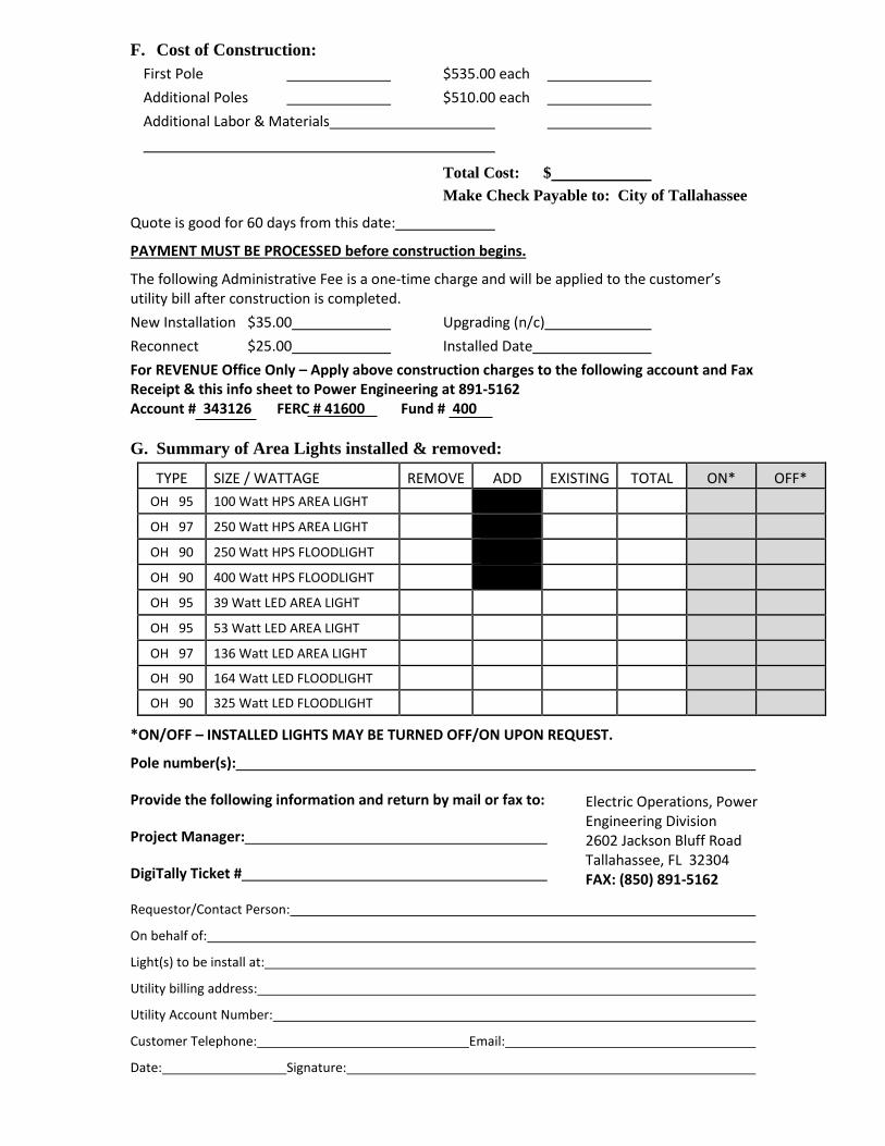
F. Cost of Construction: First Pole $535.00 each Additional Poles $510.00 each Additional Labor & Materials
Total Cost: $ Make Check Payable to: City of Tallahassee
Quote is good for 60 days from this date:
PAYMENT MUST BE PROCESSED before construction begins.
The following Administrative Fee is a one-time charge and will be applied to the customer’s utility bill after construction is completed. New Installation $35.00 Upgrading (n/c) Reconnect $25.00 Installed Date For REVENUE Office Only – Apply above construction charges to the following account and Fax Receipt & this info sheet to Power Engineering at 891-5162 Account # 343126 FERC # 41600 Fund # 400 G. Summary of Area Lights installed & removed:
TYPE SIZE / WATTAGE REMOVE ADD EXISTING TOTAL ON* OFF* OH 95 100 Watt HPS AREA LIGHT OH 97 250 Watt HPS AREA LIGHT OH 90 250 Watt HPS FLOODLIGHT OH 90 400 Watt HPS FLOODLIGHT OH 95 39 Watt LED AREA LIGHT
OH 95 53 Watt LED AREA LIGHT
OH 97 136 Watt LED AREA LIGHT
OH 90 164 Watt LED FLOODLIGHT
OH 90 325 Watt LED FLOODLIGHT
*ON/OFF – INSTALLED LIGHTS MAY BE TURNED OFF/ON UPON REQUEST.
Pole number(s):
Provide the following information and return by mail or fax to:
Project Manager:
DigiTally Ticket #
Requestor/Contact Person:
On behalf of:
Light(s) to be install at:
Utility billing address:
Utility Account Number:
Customer Telephone: Email:
Date: Signature:
Electric Operations, Power Engineering Division 2602 Jackson Bluff Road Tallahassee, FL 32304 FAX: (850) 891-5162

Access Agreement and Release The undersigned applicant having applied to the City of Tallahassee for access on or across
property owned by the City of Tallahassee, as described in the attached Exhibit A (the Property), does hereby understand and agree as follows:
1. Applicant is requesting access to property that they have legal right to access.
2. The undersigned, in consideration of being granted the requested access, shall
indemnify and hold harmless the City , its officers, officials, and employees, from liabilities, damages, losses and costs, including but not limited to reasonable attorney’s fees, to the extent caused by the negligence, recklessness, or intentional wrongful misconduct of the undersigned or persons employed or utilized by the undersigned in regard to its access to, or use of, the Property.
3. If applicant crews are to access through a live substation, City of Tallahassee crews
will be present to escort through and secure area after passing. The substation shall not be left in an open state as to allow ingress or egress.
4. If there is any damage or removal of property (i.e. Fencing or equipment), it will be
returned to the original status and/or placement by applicant before leaving the area. Witness Property Owner/Agent Signature Witness Print Property Owner/Agent Print Date Contact Phone Number City of Tallahassee Agent Property Address/Location

Secondary Service Pole Agreement and Release
The undersigned applicant having applied to the City of Tallahassee for the installation of
a secondary Service pole on property owned by the applicant does hereby understand and agree as follows:
1. The City of Tallahassee will trim trees and foliage on private property as necessary fore
the installation and maintenance of electrical. This decision will be made by the City of Tallahassee Electric Utility staff and at the request of the Customer.
2. The City of Tallahassee will not install a pole or equipment within a fenced area or
within any other area where the City does not have adequate vehicular access to the pole or equipment from the existing driveway on the applicant’s property. The applicant agrees he will not, after the installation of the pole or equipment, construct a fence, structure or any other obstacle in the area, in such a manner as to prohibit or restrict adequate vehicular access by the City of Tallahassee to the pole or equipment.
3. The City will use reasonable care in setting the subject pole and providing Service to
the pole. In consideration of the City’s provision of Service to such pole or equipment, the applicant releases and waives any and all claims that it may have at the present time, or may have in the future, on account of or in any way growing out of any damages to real or personal property (landscapes, driveways, etc.) caused by the installation and maintenance of such poles or equipment either by the personnel or equipment of the City of Tallahassee.
Witness Property Owner’s Signature Witness Print Property Owner Print Date Property Address

Electric Department Service Agreement & Release Form
The undersigned having City E&G poles and equipment on property owned by the undersigned does hereby understand and agree as follows:
1. The City will trim trees and foliage on private property as necessary for the
installation and maintenance of electrical lines. This decision will be made by E&G staff and at the request of the Customer.
2. The City not install a pole or equipment within a fenced area or within any other
area that is such that the City does not have adequate vehicular access to the pole from the existing driveway or on the applicant’s property. The applicant agrees that he/she will not, after the installation of the pole or equipment, construct a fence, structure or any other obstacle in the area, in such a manner as to prohibit or restrict adequate vehicular access by the City maintenance/construction units.
3. The City will use reasonable care in setting and/or placing poles and equipment and
providing maintenance or Service to said equipment. The applicant in consideration of the Service provided by the City hereby releases and waives any and all claims that it may have at the present time, or may hereafter have, or in any way arising out of any damage to real or personal property caused by the setting, maintenance or Service to such poles or equipment either by the personnel or equipment of the City.
4. The City will use reasonable care with vehicles on the property. In consideration
of the services rendered by the City, the Customer hereby releases and waives any and all claims that it may at the present time, or may hereafter have or may hereafer have for any damage to driveways, structures. or grass areas caused by vehicles in installing or maintaining facilities on Customer’s property.
City of Tallahassee Representative/Dept. Property Owner’s Signature Date Property Address

Page 97
14. APPENDIX E – UNDERGROUND AREA LIGHTS CUSTOMER CONTRACT

UNDERGROUND AREA LIGHTS – CUSTOMER CONTRACT (Revised 10/13/20)
A. Definition Area lights are defined as private out-door lights available for lighting yards, driveways, walkways and other areas. They are available inside the City’s Service territory and must be located in areas that are easily and economically accessible to City equipment and personnel for construction and maintenance.
B. General Policies
1. Area lights will be installed by City personnel on City or Joint User poles only. 2. Area lights shall not be placed until the applicable release forms have been signed. 3. Area light locations must be approved by a City Service representative and accessible
through the requesting customer’s property by an E&G bucket truck. 4. Customers are responsible for locating underground utilities on their property (e.g.
sprinkler systems, water lines, sewer lines, etc.). 5. Tree trimming is the responsibility of the Customer. The City may perform minor trimming
as deemed necessary by an E&G representative. 6. When new poles are installed as requested, the Customer, by his or her signature on the
request form, agrees to pay the monthly fee for the use of these facilities for a minimum of five (5) years after the date of installaton.
C. Payment for New Construction
When construction of new facilities is needed (e.g. installing new poles/wire), payment must be made at the Renaissance Building located at 435 N. Macomb St. If the customer does not already have an account with the City a customer Service representative will assist them in establishing one. After this process, the Engineer will be notified to begin the installation procedures.
D. Administrative Fees In addition to the monthly charges for area lights there is a one-time administrative fee as
follows: 1. $25.00 per account when activating an existing area light under the same account name. 2. $35.00 per account when installing a new area light on an existing pole and/or for area
lights that require setting a new pole. 3. There is no fee for upgrading an existing area light under the same account name when
upgrading requires only replacing the light fixture.
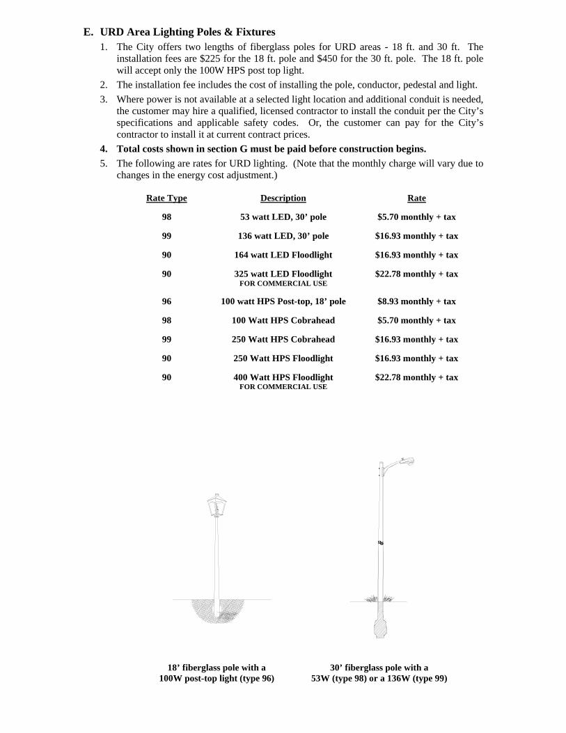
E. URD Area Lighting Poles & Fixtures 1. The City offers two lengths of fiberglass poles for URD areas - 18 ft. and 30 ft. The
installation fees are $225 for the 18 ft. pole and $450 for the 30 ft. pole. The 18 ft. pole will accept only the 100W HPS post top light.
2. The installation fee includes the cost of installing the pole, conductor, pedestal and light. 3. Where power is not available at a selected light location and additional conduit is needed,
the customer may hire a qualified, licensed contractor to install the conduit per the City’s specifications and applicable safety codes. Or, the customer can pay for the City’s contractor to install it at current contract prices.
4. Total costs shown in section G must be paid before construction begins. 5. The following are rates for URD lighting. (Note that the monthly charge will vary due to
changes in the energy cost adjustment.) Rate Type Description Rate
98 53 watt LED, 30’ pole $5.70 monthly + tax
99 136 watt LED, 30’ pole $16.93 monthly + tax
90 164 watt LED Floodlight $16.93 monthly + tax
90 325 watt LED Floodlight $22.78 monthly + tax FOR COMMERCIAL USE
96 100 watt HPS Post-top, 18’ pole $8.93 monthly + tax
98 100 Watt HPS Cobrahead $5.70 monthly + tax
99 250 Watt HPS Cobrahead $16.93 monthly + tax
90 250 Watt HPS Floodlight $16.93 monthly + tax
90 400 Watt HPS Floodlight $22.78 monthly + tax FOR COMMERCIAL USE
18’ fiberglass pole with a 30’ fiberglass pole with a 100W post-top light (type 96) 53W (type 98) or a 136W (type 99)
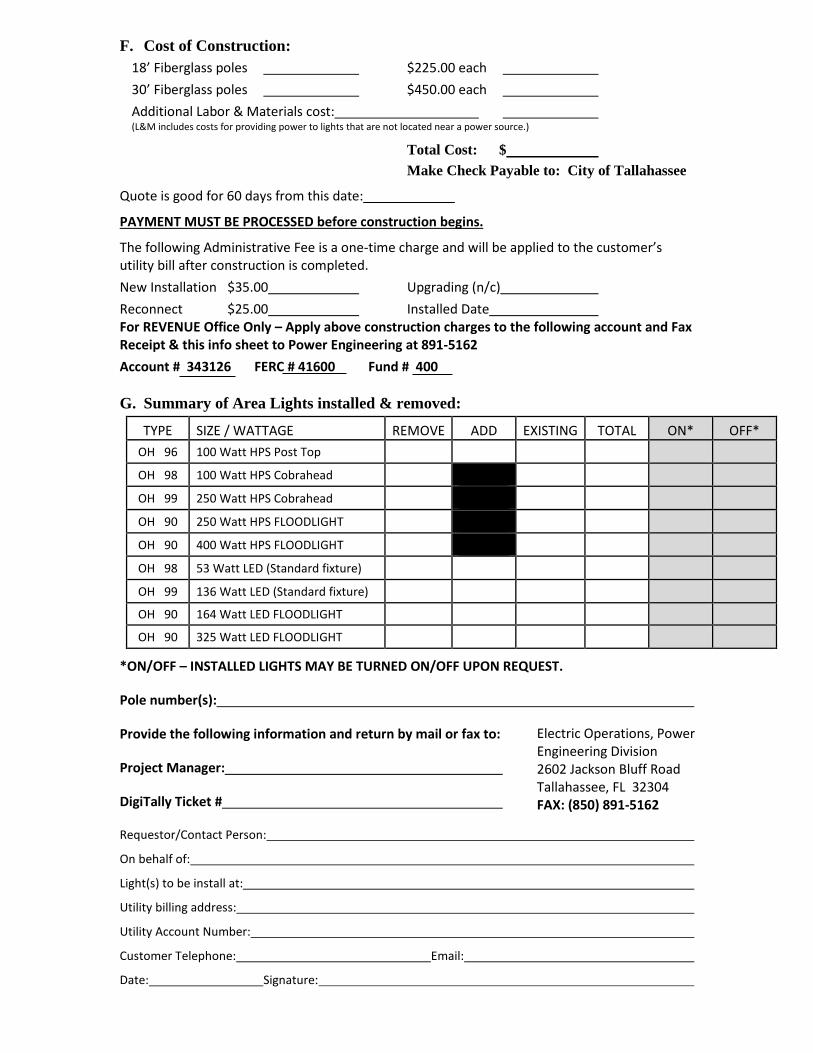
F. Cost of Construction: 18’ Fiberglass poles $225.00 each 30’ Fiberglass poles $450.00 each Additional Labor & Materials cost: (L&M includes costs for providing power to lights that are not located near a power source.)
Total Cost: $ Make Check Payable to: City of Tallahassee
Quote is good for 60 days from this date:
PAYMENT MUST BE PROCESSED before construction begins.
The following Administrative Fee is a one-time charge and will be applied to the customer’s utility bill after construction is completed. New Installation $35.00 Upgrading (n/c) Reconnect $25.00 Installed Date For REVENUE Office Only – Apply above construction charges to the following account and Fax Receipt & this info sheet to Power Engineering at 891-5162 Account # 343126 FERC # 41600 Fund # 400 G. Summary of Area Lights installed & removed:
TYPE SIZE / WATTAGE REMOVE ADD EXISTING TOTAL ON* OFF* OH 96 100 Watt HPS Post Top OH 98 100 Watt HPS Cobrahead
OH 99 250 Watt HPS Cobrahead
OH 90 250 Watt HPS FLOODLIGHT
OH 90 400 Watt HPS FLOODLIGHT
OH 98 53 Watt LED (Standard fixture)
OH 99 136 Watt LED (Standard fixture)
OH 90 164 Watt LED FLOODLIGHT
OH 90 325 Watt LED FLOODLIGHT
*ON/OFF – INSTALLED LIGHTS MAY BE TURNED ON/OFF UPON REQUEST.
Pole number(s):
Provide the following information and return by mail or fax to:
Project Manager:
DigiTally Ticket #
Requestor/Contact Person:
On behalf of:
Light(s) to be install at:
Utility billing address:
Utility Account Number:
Customer Telephone: Email:
Date: Signature:
Electric Operations, Power Engineering Division 2602 Jackson Bluff Road Tallahassee, FL 32304 FAX: (850) 891-5162

Access Agreement and Release
The undersigned applicant having applied to the City of Tallahassee for access on or across property owned by the City of Tallahassee, as described in the attached Exhibit A (the Property), does hereby understand and agree as follows:
1. Applicant is requesting access to property that they have legal right to access.
2. The undersigned, in consideration of being granted the requested access, shall
indemnify and hold harmless the City , its officers, officials, and employees, from liabilities, damages, losses and costs, including but not limited to reasonable attorney’s fees, to the extent caused by the negligence, recklessness, or intentional wrongful misconduct of the undersigned or persons employed or utilized by the undersigned in regard to its access to, or use of, the Property.
3. If applicant crews are to access through a live substation, E&G personnel will be present to escort through and secure area after passing. The substation shall not be left in an open state as to allow ingress or egress.
4. If there is any damage or removal of property (i.e. Fencing or equipment), it will be
returned to the original status and/or placement by applicant before leaving the area. Witness Property Owner/Agent Signature Witness Print Property Owner/Agent Print Date Contact Phone Number City of Tallahassee Agent Property Address/Location

Secondary Service Pole Agreement and Release
The undersigned applicant having applied to the City of Tallahassee for the installation of a secondary Service pole on property owned by the applicant does hereby understand and agree as follows:
1. The City of Tallahassee will trim trees and foliage on private property as necessary fore
the installation and maintenance of electrical. This decision will be made by the City of Tallahassee Electric Utility staff and at the request of the Customer.
2. The City of Tallahassee will not install a pole or equipment within a fenced area or
within any other area where the City does not have adequate vehicular access to the pole or equipment from the existing driveway on the applicant’s property. The applicant agrees he will not, after the installation of the pole or equipment, construct a fence, structure or any other obstacle in the area, in such a manner as to prohibit or restrict adequate vehicular access by the City of Tallahassee to the pole or equipment.
3. The City will use reasonable care in setting the subject pole and providing Service to
the pole. In consideration of the City’s provision of Service to such pole or equipment, the applicant releases and waives any and all claims that it may have at the present time, or may have in the future, on account of or in any way growing out of any damages to real or personal property (landscapes, driveways, etc.) caused by the installation and maintenance of such poles or equipment either by the personnel or equipment of the City of Tallahassee.
Witness Property Owner’s Signature Witness Print Property Owner Print Date Property Address

Electric & Gas Service Agreement & Release Form
The undersigned having City E&G poles and equipment on property owned by the undersigned does hereby understand and agree as follows:
1. The City will trim trees and foliage on private property as necessary for the
installation and maintenance of electrical lines. This decision will be made by E&G staff and at the request of the Customer.
2. The City not install a pole or equipment within a fenced area or within any other
area that is such that the City does not have adequate vehicular access to the pole from the existing driveway or on the applicant’s property. The applicant agrees that he/she will not, after the installation of the pole or equipment, construct a fence, structure or any other obstacle in the area, in such a manner as to prohibit or restrict adequate vehicular access by the City maintenance/construction units.
3. The City will use reasonable care in setting and/or placing poles and equipment and
providing maintenance or Service to said equipment. The applicant in consideration of the Service provided by the City hereby releases and waives any and all claims that it may have at the present time, or may hereafter have, or in any way arising out of any damage to real or personal property caused by the setting, maintenance or Service to such poles or equipment either by the personnel or equipment of the City.
4. The City will use reasonable care with vehicles on the property. In consideration
of the services rendered by the City, the Customer hereby releases and waives any and all claims that it may at the present time, or may hereafter have or may hereafer have for any damage to driveways, structures. or grass areas caused by vehicles in installing or maintaining facilities on Customer’s property.
City of Tallahassee Representative/Dept. Property Owner’s Signature Date Property Address

Page 104
15. APPENDIX F – OVERHEAD AREA LIGHTS CUSTOMER CONTRACT - TALQUIN

OVERHEAD AREA LIGHTS (TALQUIN SYSTEM) – CUSTOMER CONTRACT (Revised 10/13/20)
A. Definition Area lights are defined as private out-door lights available for lighting yards, driveways, walkways and other areas. They are available inside the City’s Service territory and must be located in areas that are easily and economically accessible to city equipment and personnel for construction and maintenance.
B. General Policies
1. Area lights shall not be placed until the applicable release forms have been signed.
2. Area light locations must be approved by a City service representative and accessible through the requesting Customer’s property by a bucket truck.
3. Customers are responsible for locating underground utilities on their property (e.g. sprinkler systems, water lines, sewer lines, etc.).
4. Tree trimming is the responsibility of the Customer.
5. When new poles are installed as requested, the Customer, by his or her signature on the request form agrees to pay the monthly fee for the use of these facilities for a minimum of five (5) years after the date of installation.
C. Payment for New Construction
When construction of new facilities is needed (e.g. installing new poles/wire), payment must be made at the Renaissance Building located at 435 N. Macomb St. If the customer does not already have an account with the COT a customer Service representative will assist them in establishing one. After this process, the Engineer will be notified to begin the installation procedures.
D. Administrative Fees In addition to the monthly charges for area lights there is a one-time administrative fee as
follows: 1. $25.00 per account when activating an existing area light under the same account name. 2. $35.00 per account when installing a new area light on an existing pole and/or for area lights that
require setting a new pole. 3. There is no fee for upgrading an existing area light under the same account name when upgrading
requires only replacing the light fixture. E. City Customers/Talquin Facilities
Talquin Electric Cooperative, Inc. offers only a 70-watt over-head area light that is similar in appearance to the City’s 100-watt area light. Customers served by Talquin facilities will be billed the same monthly rate as the City’s 100W HPS area light (Code 95). General policies and administrative fees are applied the same as lights installed on City facilities. However, City representatives must request this work to be done by Talquin Electric. In locations where both City and Talquin facilities are located in the area where lighting is desired, the light shall be installed on the City’s poles whenever possible.

F. Overhead Area Lighting Poles & Fixtures 1. The City offers a 35 ft. wood pole for mounting an area light. The installation cost is $535.00 for
the first pole and $510.00 per pole thereafter.
G. Cost of Construction: First Pole $535.00 each Additional Poles $510.00 each Additional Labor & Materials
Total Cost: $
Quote is good for 60 days from this date:
CHECK MUST BE RECEIVED before construction begins. Make Check Payable to: City of Tallahassee
The following Administrative Fee is a one-time charge and will be applied to the customer’s utility bill: New Installation $35.00 Upgrading (n/c) Reconnect $25.00 Installed Date For REVENUE Office Only – Apply above construction charges to the following account and Fax Receipt & this info sheet to Power Engineering at 891-5162
Account # 343126 FERC # 41600 Fund # 400 H. Summary of Area Lights installed & removed:
TYPE SIZE / WATTAGE REMOVE ADD EXISTING TOTAL ON* OFF* OH 95 70 Watt HPS (Talquin Standard)
*ON/OFF – INSTALLED LIGHTS MAY BE TURNED ON/OFF UPON REQUEST.
Pole number(s):
Provide the following information and return by mail or fax to:
Project Manager:
DigiTally Ticket #
Requestor/Contact Person:
On behalf of:
Light(s) to be install at:
Utility billing address:
Utility Account Number:
Customer Telephone: Email:
Date: Signature:
Electric Operations, Power Engineering Division 2602 Jackson Bluff Road Tallahassee, FL 32304 FAX: (850) 891-5162

Page 107
16. APPENDIX G – UNDERGROUND AREA LIGHTS CUSTOMER CONTRACT – TALQUIN

UNDERGROUND AREA LIGHTS (TALQUIN SYSTEM) – CUSTOMER CONTRACT (Revised 10/13/20)
A. Definition Area lights are defined as private out-door lights available for lighting yards, driveways, walkways and other areas. They are available inside the City’s Service territory and must be located in areas that are easily and economically accessible to city equipment and personnel for construction and maintenance.
B. General Policies
1. Area lights shall not be placed until the applicable release forms have been signed. 2. Area light locations must be approved by a City Service representative and accessible through the
requesting customer’s property by a City bucket truck. 3. Customers are responsible for locating underground utilities on their property (e.g. sprinkler
systems, water lines, sewer lines, etc.). 4. Tree trimming is the responsibility of the Customer. The City may perform minor trimming as
deemed necessary by an E&G representative. 5. When new poles are installed as requested, the Customer, by his or her signature on the request
form, agrees to pay the monthly fee for the use of these facilities for a minimum of five (5) years after the date of installation.
C. Payment for New Construction
When construction of new facilities is needed (e.g. installing new poles/wire), payment must be made at the Renaissance Building located at 435 N. Macomb St. If the customer does not already have an account with the COT a customer Service representative will assist them in establishing one. After this process, the Engineer will be notified to begin the installation procedures.
D. Administrative Fees In addition to the monthly charges for area lights there is a one-time administrative fee as follows:
1. $25.00 per account when activating an existing area light under the same account name. 2. $35.00 per account when installing a new area light on an existing pole and/or for area lights that
require setting a new pole. 3. There is no fee for upgrading an existing area light under the same account name when upgrading
requires only replacing the light fixture. E. City Customers/Talquin Facilities
Talquin Electric Cooperative, Inc. only offers a 50-watt light on a 16’ fiberglass pole for underground lighting installations. Customers served by Talquin facilities will be billed the same monthly rate as the City’s 100W HPS area light on an 18’ pole (Code 96). General policies and administrative fees are applied the same as lights installed on City facilities. A City representative will coordinate new installation of these facilities when required; however, City representatives must request this work to be done by Talquin Electric. Talquin Electric will install and maintain the facilities until the scheduled purchase of facilities to City of Tallahassee.

F. URD Area Lighting Poles & Fixtures 1. The City offers a 16’ fiberglass poles with a 50-watt light where facilities are served by Talquin.
The installation fee is $225 for the 16 ft. pole. 2. Where power is not available at a selected light location and additional conduit is needed, the
customer may hire a qualified, licensed contractor to install the conduit per the Talquin’s specifications and applicable safety codes. Or, the customer can pay for the Talquin’s contractor to install it at current contract prices.
3. Total costs shown in section G must be paid before construction begins. 4. The monthly light rate is $8.43 monthly + tax; and this rate will vary due to changes in the energy
cost adjustment. G. Cost of Construction: 16’ Fiberglass poles $225.00 each Additional Labor & Materials cost: (L&M includes costs for providing power to lights that are not located near a power source.)
Total Cost: $
Quote is good for 60 days from this date:
CHECK MUST BE RECEIVED before construction begins. Make Check Payable to: City of Tallahassee
The following Administrative Fee is a one-time charge and will be applied to the customer utility bill: New Installation $35.00 Upgrading (n/c) Reconnect $25.00 Installed Date For Office Only Account # 343126 FERC # 41600 Fund # 400
H. Summary of Area Lights installed & removed:
TYPE SIZE / WATTAGE REMOVE ADD EXISTING TOTAL ON* OFF* OH 96 50 Watt HPS on a 16’ pole
*ON/OFF – INSTALLED LIGHTS MAY BE TURNED ON/OFF UPON REQUEST.
Pole number(s)
Provide the following information and return by mail or fax to:
Project Manager:
DigiTally Ticket #
Requestor/Contact Person:
On behalf of:
Light(s) to be install at:
Utility billing address:
Utility Account Number:
Customer Telephone: Email:
Date: Signature:
Electric Operations, Power Engineering Division 2602 Jackson Bluff Road Tallahassee, FL 32304 FAX: (850) 891-5162