electric service requirements - saskpower
TRANSCRIPT

SaskPower Electric Service Requirements Revision 2 March 19, 2021
1
Electric Service Requirements
SaskPower Electric Service Requirements Revision 2 March 19, 2021
2
Table of Contents 1. General Requirements ................................................................................................................7
1.1 Electric Service Requirements Review Committee ....................................................................... 7 1.2 Introduction .................................................................................................................................. 7 1.3 Definitions ..................................................................................................................................... 8 1.4 Standard Supply .......................................................................................................................... 10
1.4.1 SaskPower Supplied Transformation ..................................................................................................... 10 1.4.2 Load Limits at Service Voltages Above 5 kV ........................................................................................... 11
1.5 Customer Leased SaskPower Owned Substations ...................................................................... 11 1.6 Customer Generation Programs ................................................................................................. 11
1.6.1 Net Metering Program ........................................................................................................................... 12 1.6.2 Customer Behind the Meter Program ................................................................................................... 12 1.6.3 Power Generation Partner Program ...................................................................................................... 12
1.7 Conditions of Service .................................................................................................................. 12 1.7.1 Application for Service ........................................................................................................................... 12 1.7.2 Construction Charge Quotations ........................................................................................................... 12 1.7.3 Electrical Service Agreements ................................................................................................................ 12 1.7.4 Permits, Notices, and Orders ................................................................................................................. 13 1.7.5 VA Demand ............................................................................................................................................ 14 1.7.6 Seals and Locks ...................................................................................................................................... 14 1.7.7 Customer Instrumentation .................................................................................................................... 14 1.7.8 Electrical Protection of Customer Equipment ....................................................................................... 14 1.7.9 Access..................................................................................................................................................... 14 1.7.10 Safety Labelling ...................................................................................................................................... 15
2. Technical Requirements for Service up to and Including 5 kV ..................................................... 15
2.1 Residential ................................................................................................................................... 15 2.1.1 General Requirements ........................................................................................................................... 15 2.1.2 Buried Service Requirements ................................................................................................................. 16 2.1.3 Aerial Service Requirements – Limited to Specific Conditions .............................................................. 17
2.2 Farm ............................................................................................................................................ 18 2.2.1 General Requirements ........................................................................................................................... 18 2.2.2 Buried Service Requirements ................................................................................................................. 18
2.3 General Service ........................................................................................................................... 20 2.3.1 General Requirements ........................................................................................................................... 20 2.3.2 Buried Service Requirements ................................................................................................................. 21 2.3.3 Aerial Service Requirements – Limited to Specific Conditions .............................................................. 23
2.4 Oilfield ......................................................................................................................................... 23 2.4.1 General Requirements ........................................................................................................................... 23 2.4.2 Buried Service Requirements ................................................................................................................. 24
2.5 Metering ..................................................................................................................................... 25 2.5.1 General Requirements ........................................................................................................................... 25 2.5.2 Meter Mounting Devices ....................................................................................................................... 25 2.5.3 Instrument Transformers and Enclosures .............................................................................................. 28 2.5.4 Metering Signals .................................................................................................................................... 30
2.6 Installation Diagrams for Services up to and Including 5 kV ....................................................... 31 2.7 Tables for Services up to and Including 5 kV .............................................................................. 68
SaskPower Electric Service Requirements Revision 2 March 19, 2021
3
3. SaskPower System Characteristics and Power Quality Requirements for Customer Loads ........... 74
3.1 Power Quality.............................................................................................................................. 74 3.2 Characteristics of the SaskPower System ................................................................................... 74
3.2.1 Frequency and Frequency Variation ...................................................................................................... 74 3.2.2 Normal Voltage Variation ...................................................................................................................... 74 3.2.3 Temporary Voltage Disturbances .......................................................................................................... 75 3.2.4 System Voltage Unbalance .................................................................................................................... 78 3.2.5 Harmonic Voltage Distortion ................................................................................................................. 79 3.2.6 Single Phase Tripping and Automatic Reclosing .................................................................................... 79 3.2.7 System Fault Levels and System Impedences ........................................................................................ 80
3.3 Limits on Voltage Disturbances Caused by Customer Loads ...................................................... 81 3.3.1 Infrequent Voltage Fluctuations (up to Once per Day) Caused by Customer Equipment ..................... 81 3.3.2 Voltage Fluctuations Caused by Customer Equipment with a Rate of Occurrence between Once per Day and Once per Minute ................................................................................................................................... 83 3.3.3 Voltage Fluctuations Caused by Customer Equipment with a Rate of Occurrence of Once per Minute or Higher (Flicker) ............................................................................................................................................... 84 3.3.4 Limits on Commutation Notches ........................................................................................................... 88
3.4 Limits on Current Distortion Caused by Customer Loads ........................................................... 89 3.4.1 Harmonic Current Limits ........................................................................................................................ 89 3.4.2 Protocol for Measurement of Harmonic Currents ................................................................................. 92
4. Requirements for Customer Owned Substations Greater Than 5 kV ........................................... 94
4.1 Jurisdiction .................................................................................................................................. 94 4.1.1 SaskPower Electrical Inspections Division ............................................................................................. 94 4.1.2 SaskPower Transmission and Distribution ............................................................................................. 94 4.1.3 SaskPower Customer Services ............................................................................................................... 94
4.2 General Requirements ................................................................................................................ 95 4.2.1 Voltages ................................................................................................................................................. 95 4.2.2 SaskPower Required Drawings .............................................................................................................. 95
4.3 Service Requirements ................................................................................................................. 95 4.3.1 Extending Supply Service from 15 kV or 25 kV System .......................................................................... 95 4.3.2 Extending Supply Service from 72 kV, 138 kV, or 230 kV Aerial System................................................ 96 4.3.3 Metering ................................................................................................................................................ 96
4.4 Specifications ............................................................................................................................ 102 4.4.1 Aerial Supply Conductors ..................................................................................................................... 102 4.4.2 Electrical Characteristics within Substations – External Clearances in Air ........................................... 103 4.4.3 Protection of Substation Equipment ................................................................................................... 104 4.4.4 Protection Coordination ...................................................................................................................... 104 4.4.5 Customer Equipment Coordination ..................................................................................................... 105 4.4.6 Disconnection of Substation from Transmission Line .......................................................................... 105 4.4.7 Phase Rotation ..................................................................................................................................... 106 4.4.8 Ambient Conditions ............................................................................................................................. 106
4.5 Figures ....................................................................................................................................... 107
SaskPower Electric Service Requirements Revision 2 March 19, 2021
4
List of Figures Figure 2-1A: Single Phase 120/240V 3W 200A Buried Service Meter Installation ..................................................... 32 Figure 2-2A: Three-Phase 120/208V 4W 200A Buried Service Meter Installation ..................................................... 35 Figure 2-3: Single Phase 120/240V 3W 200A Meter Socket Mounted on Stub Pole .................................................. 38 Figure 2-4: Single Family Dwelling Gas and Electrical Meter Installation ................................................................... 39 Figure 2-5: Single Phase 120/240V 3W 400A or 600A Customer Service Termination Enclosure .............................. 40 Figure 2-6: Three Phase 120/208V 4W 400A or 600A Customer Service Termination Enclosure .............................. 41 Figure 2-7: Single Phase 120/240V 3W Multi-Position Meter Trough with Blank Compartment .............................. 42 Figure 2-8: Single Phase 120/240V 3W Splitter with (Multi-Position) Meter Trough................................................. 43 Figure 2-9: Single Phase 120/240V 3W or Three Phase 120/208V 4W Splitter with Multiple Meters ....................... 44 Figure 2-10: Outside Splitter ....................................................................................................................................... 45 Figure 2-11: Single Phase 3W or Three Phase 4W Exceeding 200A............................................................................ 46 Figure 2-12: Multi-Meter Center – Customer Assembled Unit................................................................................... 47 Figure 2-13: Padmount Distribution Center ............................................................................................................... 48 Figure 2-14: Single Phase 3W or Three Phase 4W Over 300V Up to 200A ................................................................. 49 Figure 2-15: Single Phase 120/240V 3W 100A or 200A Rural Metering (Free Standing Pedestal) ............................. 50 Figure 2-16: Single Phase 120/240V 3W 100A or 200A Rural Metering (RUD Transformer) ..................................... 51 Figure 2-17: Single Phase 120/240V 3W 100A or 200A Rural Metering (Pole Mounted) .......................................... 52 Figure 2-18: Single Phase 120/240V or 240/480V 3W 100A or 200A Rural F-Cabinet ............................................... 53 Figure 2-19: Three Phase (up to 347/600V) 4W 200A Rural F-Cabinet ...................................................................... 54 Figure 2-20: Oilfield Customer Cable Marking ............................................................................................................ 55 Figure 2-21: Three Phase Pad-Mount Transformer with Attached Metering Over 200A ........................................... 56 Figure 2-22: Cable Routing in Pad-Mount Transformer Vault .................................................................................... 57 Figure 2-23: Customer Cable Support in Pad-Mount Transformer ............................................................................. 58 Figure 2-24: Clearances for Aerial Services ................................................................................................................. 59 Figure 2-25: Pad-Mount Transformer Clearances for Inset into Buildings ................................................................. 60 Figure 2-26: Pad-Mount Transformer Clearances (Enclosure and Barrier) ................................................................ 61 Figure 2-27: Meter Socket Requirements ................................................................................................................... 62 Figure 2-28: Socket Connection Diagrams for Self-Contained Meters ....................................................................... 63 Figure 2-29: Current Transformer Connection Diagrams ........................................................................................... 64 Figure 2-30: Indoor Current Transformers – 5 kV Class .............................................................................................. 65 Figure 2-31: Indoor Voltage Transformers – 5 kV Class .............................................................................................. 66 Figure 2-32: Customer Owned 5 kV Live-Front Switchgear (Typical) ......................................................................... 67 Figure 3-1: Definition of Pre-Disturbance and Disturbance Voltage .......................................................................... 82 Figure 3-2: Limits on Acceptable Voltage Fluctuations with Occurrence Rate between Once per Day and Once per Minute ......................................................................................................................................................................... 83 Figure 3-3: Example of 60 Hz Supply Voltage Modulated by a 0.42 Vrms Rectangular Voltage Function ................. 84 Figure 3-4: Example of the Cumulative Distribution of Plt over the Measurement Period ........................................ 86 Figure 3-5: Normalized Flickermeter Response for Rectangular Voltage Fluctuations .............................................. 87 Figure 3-6: Definition of % Notch Depth ..................................................................................................................... 89 Figure 4-1: Customer Owned Overhead 15 kV or 25 kV Facilities ............................................................................ 108 Figure 4-2: Customer Owned 15 kV or 25 kV Live-front Switchgear (Typical) .......................................................... 109 Figure 4-3: Customer Owned 15 kV or 25 kV Dead-Front Switchgear (Typical) ....................................................... 110 Figure 4-4: Conduit, Pull Boxes, and Junction Box for 72 kV Outdoor Instrument Transformer Secondary ............ 111

SaskPower Electric Service Requirements Revision 2 March 19, 2021
5
Figure 4-5: Conduit, Pull Boxes, and Junction Box for 138 kV or 230 kV Outdoor Instrument Transformer Secondary ................................................................................................................................................................................... 112 Figure 4-6 (Sheet 1 of 2): 72 kV, 138 kV, and 230 kV Termination Structure (Typical)............................................. 113 Figure 4-6 (Sheet 2 of 2): 72 kV, 138 kV, and 230 kV Termination Structure (Typical)............................................. 114
SaskPower Electric Service Requirements Revision 2 March 19, 2021
6
List of Tables
Table 1-1: Maximum Load for Service Requests......................................................................................................... 11 Table 2-1: Buried Service Conductor Enclosure and Conduit Sizes ............................................................................ 69 Table 2-2: Separation Requirements for Buried Conductors for Voltages up to and Including 25 kV in Rural and Urban Areas ................................................................................................................................................................. 70 Table 2-3: Oilfield and Gas Field Clearance Requirements from Conductors Operating at Voltages up to and Including 25 kV ............................................................................................................................................................ 72 Table 2-4: Minimum Design Clearances for Overhead Lines Operating at Voltages up to and Including 25 kV ........ 73 Table 3-1: CEA Power Quality Survey Results ............................................................................................................. 76 Table 3-2: SaskPower’s Voltage Distortion Guidelines ............................................................................................... 79 Table 3-3: Normalized Flickermeter Response for Rectangular Voltage Fluctuations ............................................... 87 Table 3-4: Limits on Commutation Notches ............................................................................................................... 88 Table 3-5: IDFh and THD Limits for Service Voltages less than 72 kV .......................................................................... 90 Table 3-6: IDFh and THD Limits for Service Voltages 72 kV and Above ....................................................................... 90 Table 3-7: Balanced and Residual I*T Limits ............................................................................................................... 91 Table 3-8: List of Values of Relative 1960 Single Frequency Telephone Influence Factor Th...................................... 91
SaskPower Electric Service Requirements Revision 2 March 19, 2021
7
1. General Requirements
1.1 Electric Service Requirements Review Committee
The members of the SaskPower Electric Service Requirements review committee are:
Marvin Ereth Specialist Human Resources and Safety – Electrical Safety
Ryan Funk District Operator Distribution and Customer Services – Operating (Prince Albert Central)
Brian Hall Specialist Distribution and Customer Services – Customer Relations
Matthew Kowalyshen Manager Distribution and Customer Services – Distribution Engineering (Committee Chair)
Bin Lu Engineer Distribution and Customer Services – Metering Services
Kevin Kobitz Manager Distribution and Customer Services – Operating (Moose Mountain)
Rod Pack Manager Law, Land, and Regulatory Affairs – Electrical Inspections (North)
Dean Schill Manager Distribution and Customer Services – Metering Services
Terry Wasylynka Manager Distribution and Customer Services – Policy and Administration
Colin Wensley Manager Asset Management, Planning, and Sustainability – Distribution Asset Management and Planning
Len Yee Engineer Asset Management, Planning, and Sustainability – Technical Development and Standards
A copy of this document is located on SaskPower’s website Electric Service Requirements (saskpower.com). Please refer to the website for the most recent revision of this document.
1.2 Introduction
SaskPower’s Electric Service Requirements have been prepared to provide requirements for the connection of electrical service to SaskPower’s facilities. The intent of these requirements is to ensure conformity to the Code, provide for protection of personnel and equipment, and recognize operational needs; while providing as many options as reasonable for the connection of electrical service to SaskPower's facilities. All new utility service connections are required to comply with the current requirements of SaskPower’s Electric Service Requirements and current addendums. In process applications shall comply with requirements and addendums current on the date listed in the formal construction agreement between SaskPower and the
SaskPower Electric Service Requirements Revision 2 March 19, 2021
8
Customer. Existing installations will be required to be modified, as required, to comply with the most current requirements of SaskPower’s Electric Service Requirements and subsequent addendums in the following cases:
• When the service has been disconnected for a period of more than twelve (12) months. • When the installation requires upgrades due to fire or flood. • When the installation is undergoing renovations that require an electrical permit and include any
modification to the point of delivery or meter installation. SaskPower reserves the right to enforce, at its sole discretion, any requirement, on any service installation, at any time, to ensure the safety of the public, SaskPower’s contractors, and SaskPower’s staff. Failure to comply with a request for alteration or modification to a proposed or existing service may result in refusal to energize or disconnection from SaskPower’s system. For Non-Utility Generation requirements also refer to the following SaskPower documents, as applicable, which can be found at Electric Service Requirements (saskpower.com):
Generation Interconnection Requirements at Voltages 34.5 kV and Below Non-Utility Generation Interconnection Requirements at Voltages 72 kV and Above
SaskPower Electrical Inspections Division, by the authority of the Electrical Inspection Act for Saskatchewan and CSA C22.1 (Canadian Electrical Code, Part I), and Saskatchewan Amendments, has complete authority beyond the point of delivery. Deviations to the Electric Service Requirements may be considered. Requests for deviations must be made in writing and be accompanied by proposed installation drawings. In order to be properly reviewed, SaskPower must receive the request a minimum of one month prior to construction. If approval is granted, it is only valid for the service installation in question and is not general approval for future services. Permission to deviate from the Electric Service Requirements is granted by the appropriate SaskPower Engineering Manager. Only Electrical Inspections has the authority to grant deviations derived from and stated in the Code. Deviation requests and suggestions for changes to the Electric Service Requirements can be forwarded to the Committee Chair.
1.3 Definitions
Aerial Service Aerial secondary conductor from an overhead transformer to the point of delivery.
Aerial System SaskPower's Distribution System when high voltage primary conductor(s) are installed on poles and extended to pole-mount transformers.
Building A structure which is detached, or separated, from adjoining structures by fire rated walls as per National Building Code of Canada.
Buried Service Buried secondary conductors from the transformer to the point of delivery.
Buried System SaskPower's Distribution System when high voltage primary conductor(s) are buried and normally extended to pad-mount transformers.

SaskPower Electric Service Requirements Revision 2 March 19, 2021
9
Code CSA C22.1 Canadian Electrical Code, Part 1, and Saskatchewan Amendments issued by SaskPower Electrical Inspections Division.
Condominium – Bare Land
Single family apartments, row-housing units, townhouses, and duplexes where each unit (including the land) is individually titled. These units are required to be serviced as single family detached dwellings.
Condominium - Conventional
Single family apartments, row-housing units, townhouses, and duplexes where the units are individually titled, and the common ground is held in joint ownership.
Customer’s Service All that portion of the Customer's installation from the service box (main disconnect) or its equivalent up to and including the point of delivery.
Customer Service Termination Enclosure (CSTE)
A dedicated approved enclosure, provided by the Customer, for termination of utility service conductors at 120/240 V or 120/208 V, with entrance ratings of 400 A or 600 A. Refer to Section 2.5.3.3 and Figures 2-5/2-6 for a complete list of CSTE requirements.
Dedicated Service A utility service, with individual or parallel runs of service cable, that is the only service originating from the utility source (transformer), that serves only one Customer metering point.
Different Voltages & Electrical Characteristics
A system having a different voltage and/or a different number of phases. Within the same building, one service must be for dedicated loads (rather than for general distribution).
Main Disconnect/Service Box
An approved assembly consisting of a metal box or cabinet constructed so that it may be effectually locked or sealed, containing either service fuses and a service switch or a circuit breaker, and of such design that either the switch or circuit breaker may be manually operated when the box is closed.
Metering Cabinet An assembly in which instrument transformers are installed, for use in SaskPower's revenue meter.
Outside Service Splitter An enclosure applicable for outdoor use required for connection of utility conductors to the Customer's service conductors.
Paid Electrical Permit A permit is considered valid when the numbered permit and payment is received by an authorized SaskPower employee (Inspections or Customer Services).
Point of Delivery The first point of connection of SaskPower’s facilities to the Customer’s conductors or equipment, at a location designated by or satisfactory to SaskPower, without regard for the location of SaskPower’s metering equipment.
Rural The area outside of the registered limits of a city, town, or village. For the purposes of SaskPower servicing hamlets, rural communities, and resorts will not be considered rural.

SaskPower Electric Service Requirements Revision 2 March 19, 2021
10
Single Family Detached Dwelling
A separate building suitable for single family occupancy.
Splitter An enclosure containing terminal plates or bus bars having main connectors.
Urban The area within the registered limits of a city, town, or village. For the purposes of SaskPower servicing hamlets, rural communities, and resorts will be considered urban.
1.4 Standard Supply
Although every effort will be made to comply with the Customer's request, SaskPower reserves the right to determine the supply voltage and load limitations, depending upon the available source and transformation.
1.4.1 SaskPower Supplied Transformation SaskPower will provide and install outdoor transformation for Customers at the secondary supply voltages and at maximum (kVA) capacities indicated in Section 1.4.1.1 and Section 1.4.1.2 below. Polyphase service requirements outside the following limitations fall under Customer owned substations as per Section 4 or SaskPower leased substations as per Section 1.5. There may be capacity limitations when the Customer is supplied at voltages other than 25 kV.
1.4.1.1 Single Phase Supply Voltages
• 120/240 V 3-wire (167 kVA) (1) • 240/480 V 3-wire (100 kVA) • 120/208 V 3-wire (Network) (2) • 120 V 2-wire (3 kVA) (3)
Notes (1): Maximum 800 A entrance.
(2): From a polyphase service. (3): Applicable to metered signs, billboards, and unmetered services only.
1.4.1.2 Polyphase Supply Voltages
• 120/208 V grounded WYE 4-wire (750 kVA) • 277/480 V grounded WYE 4-wire (2500 kVA) • 347/600 V grounded WYE 4-wire (3000 kVA) • 2400/4160 V grounded WYE 4-wire (3000 kVA)
1.4.1.3 Existing Polyphase Supply Voltages
• 120/240 V DELTA 4-wire (1) • 480 V DELTA 3-wire (1)
Note (1): New service requests are not allowed. Capacity increases for existing Customers is
allowed provided the voltage and electrical characteristics do not change.
SaskPower Electric Service Requirements Revision 2 March 19, 2021
11
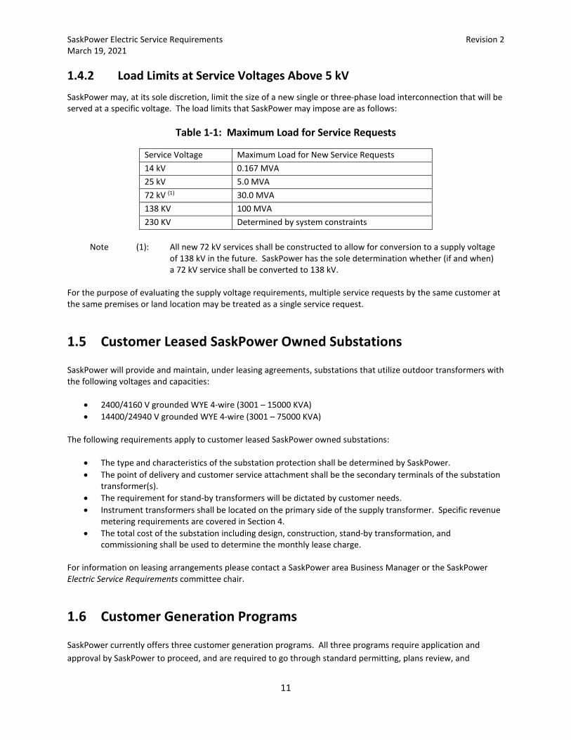
1.4.2 Load Limits at Service Voltages Above 5 kV SaskPower may, at its sole discretion, limit the size of a new single or three-phase load interconnection that will be served at a specific voltage. The load limits that SaskPower may impose are as follows:
Table 1-1: Maximum Load for Service Requests
Service Voltage Maximum Load for New Service Requests 14 kV 0.167 MVA 25 kV 5.0 MVA 72 kV (1) 30.0 MVA 138 KV 100 MVA 230 KV Determined by system constraints
Note (1): All new 72 kV services shall be constructed to allow for conversion to a supply voltage
of 138 kV in the future. SaskPower has the sole determination whether (if and when) a 72 kV service shall be converted to 138 kV.
For the purpose of evaluating the supply voltage requirements, multiple service requests by the same customer at the same premises or land location may be treated as a single service request.
1.5 Customer Leased SaskPower Owned Substations
SaskPower will provide and maintain, under leasing agreements, substations that utilize outdoor transformers with the following voltages and capacities:
• 2400/4160 V grounded WYE 4-wire (3001 – 15000 KVA) • 14400/24940 V grounded WYE 4-wire (3001 – 75000 KVA)
The following requirements apply to customer leased SaskPower owned substations:
• The type and characteristics of the substation protection shall be determined by SaskPower. • The point of delivery and customer service attachment shall be the secondary terminals of the substation
transformer(s). • The requirement for stand-by transformers will be dictated by customer needs. • Instrument transformers shall be located on the primary side of the supply transformer. Specific revenue
metering requirements are covered in Section 4. • The total cost of the substation including design, construction, stand-by transformation, and
commissioning shall be used to determine the monthly lease charge. For information on leasing arrangements please contact a SaskPower area Business Manager or the SaskPower Electric Service Requirements committee chair.
1.6 Customer Generation Programs
SaskPower currently offers three customer generation programs. All three programs require application and approval by SaskPower to proceed, and are required to go through standard permitting, plans review, and
SaskPower Electric Service Requirements Revision 2 March 19, 2021
12
approval processes as per Gas and Electrical Inspections. In addition, any utility interaction point required for the installation must comply with the applicable requirements as outlined in this document. More details on each of the programs below are located online at the following links:
Generating Power as an Individual (saskpower.com)
Generating Power as a Community or Business (saskpower.com)
1.6.1 Net Metering Program The net metering program allows customers to generate their own power to offset their electricity charges and may export power to the utility grid.
1.6.2 Customer Behind the Meter Program Customer’s can generate their own power to offset electricity charges and may do so with a utility net meter. These installations must never export power to the utility grid and must obtain approval to proceed. Applications go through the net metering process.
1.6.3 Power Generation Partner Program The Power Generation Partner Program allows customers to set up larger scale generation facilities with the intent of exporting most of the power into the utility grid.
1.7 Conditions of Service
1.7.1 Application for Service Application for service shall be made through the SaskPower website or via telephone to the SaskPower New Connect Desk (1-888-757-6937 option 4). Application shall include complete information on the service details and may require a site plan.
1.7.2 Construction Charge Quotations Upon receipt of the completed application for service, SaskPower will, within a reasonable amount of time, provide the Customer with a cost quotation and service detail covering the supply of electrical service to the Customer.
1.7.3 Electrical Service Agreements Special circumstances may dictate the desirability of obtaining a signed agreement, at the Customer's or SaskPower's request.
SaskPower Electric Service Requirements Revision 2 March 19, 2021
13
1.7.4 Permits, Notices, and Orders
1.7.4.1 Electrical Permits and Service Connections
Requests to obtain an electrical permit shall be made via telephone to the SaskPower Inspections desk (1-888-757-6937 option 5) OR email ([email protected]). For complete details on obtaining an electrical permit please visit Electrical Permits and Applications (saskpower.com). An Electrical Permit is issued by the SaskPower Electrical Inspections Division to the electrical contractors or others responsible for the permanent or temporary wiring of, or alterations to, electrical installations. Conversions from overhead to underground farmyard distribution are included. An Electrical Permit is required for services disconnected for over one year or reconnected after a fire or flood. When a permit is required for a reconnection as a result of an accident or an act of nature, or the service has been disconnected for over one year, or reconnected after a fire or flood, the service shall be required to be repaired to the current standards as per Code. This would include replacement of a wooden service mast with an approved steel service mast. SaskPower requires the following criteria to be met before the service will be energized:
• Customer application for service/meter installation, • Verification from the Electrical Permit holder or their representative that the service is ready for
connection, to be indicated on the meter socket by application of an Energization Sticker provided by SaskPower.
The Energization Sticker is the Electrical Permit holder’s assurance that:
• A paid Electrical Permit has been obtained for the service. • Wiring on the customer’s service (from the point of delivery to the main disconnect) is free from short
circuits, grounds or any defects that might cause a hazard to life or property. • The Customer’s main switch is in the open position. • Service is free of any other sources of energization (back feed). • For Services 600 amps and above, a pre-energization inspection has been performed by the Electrical
Inspections department and or they have approved the service connections. • The Customer’s service meets the Canadian Electrical Code for grounding and clearance.
An Electrical Permit is required prior to the connection of a temporary service. A separate or an additional Electrical Permit is required when transferring the service from temporary to permanent. A temporary service is valid for a period of less than two (2) years. Temporary services must be disconnected as soon as practicable after the permanent service is connected.
1.7.4.2 Contractor Notice of Electrical Defects
A Contractor Notice of Electrical Defects is issued by the SaskPower Electrical Inspections Division to a contractor to make the installation comply with the Code.
1.7.4.3 Owner Notice of Electrical Defects
An Owner Notice of Electrical Defects is issued by the SaskPower Electrical Inspections Division to the owner or occupant of a premise to make the installation comply with the Code.
SaskPower Electric Service Requirements Revision 2 March 19, 2021
14
1.7.4.4 Electrical Service Disconnection Order
When orders to correct defects or hazards are not complied with, the Supervisor Electrical Inspector can issue an Electric Service Disconnection Order to cut off service on a specific date. SaskPower will disconnect the service in question on the date specified unless arrangements have been made with the SaskPower Electrical Inspections Division. Reconnection of the service will only occur upon instruction from the SaskPower Electrical Inspections Division.
1.7.5 VA Demand Customer’s with poor power factor and connected with a VA demand meter are advised to consider power factor correction for their facilities.
1.7.6 Seals and Locks To permit access to various equipment by SaskPower employees only, seals and locks are placed on the supply equipment components, where located on the line side of the SaskPower meter. Examples of this equipment include splitters, instrument transformer compartments, meters, metering compartments, conduit fittings, Customer's service box (without fuses) and both sides of generator transfer devices mounted on the meter socket. Service boxes containing Customer fuses will not be sealed to provide free access to the fuses. Removal of a seal or lock contravenes the Power Corporation Act. Penalties, enforceable by law, may be imposed as stipulated by the Power Corporation Act. Should it be necessary to break seals to perform electrical wiring alterations, SaskPower must either remove the seal, or upon receipt of advance notification, authorize the seal(s) removal. SaskPower shall be notified by the contractor when the work is completed to reseal the service. Upon completion of the work SaskPower will reseal the installation.
1.7.7 Customer Instrumentation Customer's relays, instruments or other devices shall not be connected in SaskPower revenue metering circuits and shall not be mounted on or in any meter enclosures, instrument transformer enclosures or any other equipment supplied for use by SaskPower. Exceptions will be made for SaskPower-approved generator transfer device mounted on the meter socket.
1.7.8 Electrical Protection of Customer Equipment SaskPower shall not assume responsibility for the electrical protection of Customer-owned equipment, including that for single phasing protection. Electrical protection shall be installed as per the Code.
1.7.9 Access For all installations of SaskPower equipment (such as metering equipment or service cable terminations), SaskPower staff shall have access to all such equipment for the purpose of changing, servicing, testing and reading. Where access to the equipment is unobtainable due to locked doors, the local SaskPower office shall be provided with a key. When mutually agreeable, SaskPower will supply a lock box for storage of the key.

SaskPower Electric Service Requirements Revision 2 March 19, 2021
15
1.7.10 Safety Labelling For all devices, enclosures or equipment which SaskPower staff needs to access in providing service to Customers, SaskPower staff will apply safety labelling as per SaskPower internal standards.
2. Technical Requirements for Service up to and Including 5 kV
2.1 Residential
These requirements apply to the extension of service to any dwelling unit used primarily for domestic purposes on a permanent or seasonal basis, not including commercially operated self-contained rental units in resort areas.
2.1.1 General Requirements When an aerial or buried system exists, SaskPower will normally install a buried supply service to all new customers. However, circumstances may dictate that an aerial service remains or be installed. At the time of application for service, the Customer shall advise SaskPower of any abnormal site conditions, including those that may preclude a buried service. Clearances from the transformer to buildings shall conform to the Code and are shown in Table 2-2. When these clearances cannot be met, the Customer shall supply and install barriers between the transformer and the building as per Figures 2-25 and 2-26. Separations of SaskPower's direct buried power conductors to various facilities shall be as per Table 2-2. Clearances for aerial services shall be as per Figure 2-24. Overhead clearances, as applicable, shall be as per Table 2-4. A single meter shall measure energy consumed by a single Customer in any individual premise, including individual self-contained apartment suites within an apartment building. An apartment suite is considered self-contained if it contains sleeping quarters, bathroom facilities, and permanently installed cooking facilities. Cord connected 120 V hot plates/cook tops and/or microwaves do not constitute permanent cooking facilities. There shall be a maximum of two (2) points of delivery per building; however, a Customer cannot have two meters, at the same voltage, for the same premise. All points of delivery to a building shall come from the same transformer unless the services have different voltages and/or electrical characteristics. The ownership of facilities to the point of delivery shall remain with SaskPower, and the ownership of facilities after the point of delivery shall remain with the Customer. The location for point of service, buried or aerial, shall be at SaskPower’s sole discretion based on property configuration, design/construction constraints, and nearest supply facilities. Normally point of service will be located within one meter of the point on the building nearest to SaskPower's supply facilities. An alternate Customer preferred location may be permitted provided the location poses no immediate or future technical or physical impediment to SaskPower. An example of a technical impediment is when the increased conductor length introduces unacceptable voltage drop. Examples of physical impediments would include the following:
• Insufficient access to allow for mechanical trenching (the width of most trenchers operating for SaskPower is approximately 1.8 meters. This would require a clearance between the building and the property line of approximately 2.5 meters. Assuming that a short run (1 or 2 m) can be reached with the
SaskPower Electric Service Requirements Revision 2 March 19, 2021
16
boom of the trencher or can be hand dug, a meter socket installed at this distance from the corner of the building should not be a problem).
• Insufficient clearance from natural gas lines. • Close proximity and paralleling water or septic lines. • Existing or future decks or patios. • Asphalt, paving stone or cement. • Landscaping such as retaining walls, ponds, fabric, etc.
Customers who wish to locate their meter socket in a location other than the nearest corner to SaskPower supply facilities are advised to notify SaskPower through the SaskPower New Connect Desk (1-888-757-6937 option 4). A field representative will call to discuss the proposed location. All pre-serviced lots must meet site readiness requirements to be energized. Site readiness requirements are listed on the SaskPower website Pre-serviced Private Owner (saskpower.com). Gas and electrical meter installation requirements are contained in Figure 2-4 of this document. For all new residential service applications, the Customer is responsible for supplying secondary cable for installations where the main service size is greater than 800 amps, or where the supply service would exceed 3 conductors per phase.
2.1.2 Buried Service Requirements
2.1.2.1 Single Family Detached Dwelling – Urban Single Phase Service up to 300 V
For supply services up to 200 A, servicing options include:
• Customer supplied 200 A self-contained meter socket as per Figure 2-1. • For lots ≥ 2 acres, SaskPower supplied Rural Metering as per Figure 2-15 or Figure 2-16 or Figure 2-17. • Customer supplied outside splitter as per Figure 2-10, Figure 2-11, and Table 2-1. • Customer supplied 200 A self-contained meter socket, mounted on a stub pole, as per Figure 2-3.
For supply services greater than 200 A, servicing options include:
• Customer supplied outside splitter as per Figure 2-10, Figure 2-11, and Table 2-1. • Customer supplied single phase service termination / CT enclosure as per Figure 2-5 and Table 2-1.
2.1.2.2 Single Family Detached Dwelling – Rural Single Phase Service up to 300 V
For supply services up to 200 A, servicing options include:
• SaskPower supplied Rural Metering as per Figure 2-15 or Figure 2-16 or Figure 2-17. For supply services greater than 200 A, servicing options include:
• Customer supplied outside splitter (attached to building, or free-standing) as per Figure 2-10, Figure 2-11, and Table 2-1.
• Customer supplied single phase service termination / CT enclosure as per Figure 2-5 and Table 2-1
SaskPower Electric Service Requirements Revision 2 March 19, 2021
17
2.1.2.3 Single Family Detached Dwelling – Mobile Home (Park)
Servicing options are:
• Customer supplied 200 A self-contained meter socket as per Figure 2-1. • Customer supplied 200 A self-contained meter socket, mounted on a stub pole, as per Figure 2-3.
2.1.2.4 Multiple Single Family Dwellings
Multiple single family dwelling requirements apply to all single family row-housing units, townhouses, apartments, and duplexes. Note the requirement in Section 2.1.1 limiting the number of points of delivery to a building to a maximum of two. This requirement applies to all multiple single family services except individually titled condominium units.
The only servicing option for duplexes and individually titled condominium units is an individual Customer supplied self-contained 200 A meter socket as per Figure 2-1. SaskPower may choose to deliver service to a multi-position meter trough, as per Figure 2-7, for individually titled multiple single family units where lot size or configuration limits servicing options. Servicing options for all multiple single family dwellings other than duplexes and individually titled condominium units are listed below. For the servicing options below the Customer may supply, install, and terminate secondary conductors at the SaskPower supplied pad-mounted transformer, provided the transformer is dedicated to the Customer’s site only.
• Customer supplied service termination/CT enclosure as per Figure 2-5 and Table 2-1. • Customer supplied service termination/CT enclosure as per Figure 2-6 and Table 2-1. • Customer supplied multi-position meter trough, with blank compartment, as per Figure 2-7 and Table 2-1. • Customer supplied outside splitter with horizontal multi-meter trough(s) as per Figure 2-8, Figure 2-10,
and Table 2-1. • Customer supplied outside splitter with multiple meter sockets as per Figure 2-9, Figure 2-10, and Table 2-
1. • Customer supplied splitter as per Figure 2-10, Figure 2-11, and Table 2-1. • Customer supplied outside splitter with a multi-meter center as per Figure 2-10, Figure 2-12, and Table 2-
1. • Customer supplied switchgear. (1)
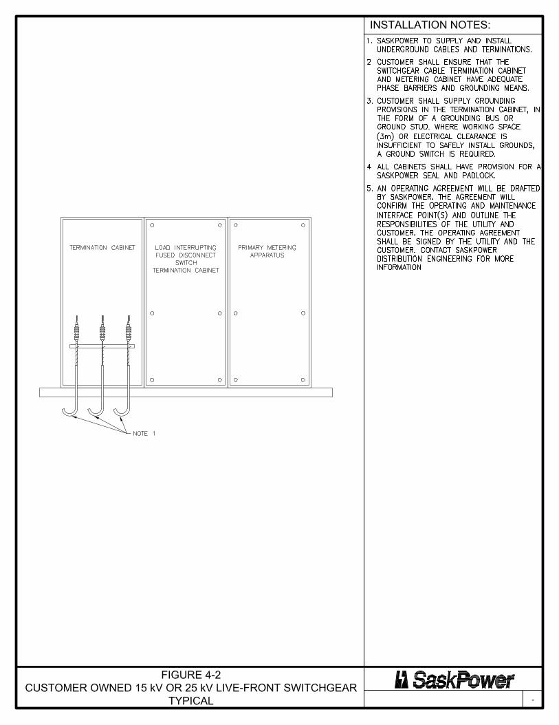
Note (1): The Customer shall ensure that when SaskPower extends high voltage supply cables to the
Customer's cable termination compartment in the switchgear, the compartment shall have adequate phase barriers and grounding means.
2.1.3 Aerial Service Requirements – Limited to Specific Conditions Aerial residential supply services shall be limited to 200 A and may apply to any type of residential dwelling. New residential aerial service requests will only be allowed, at SaskPower’s sole discretion, in areas with rocky or steep terrain that makes underground construction methods impractical. The Customer shall provide the means of attachment for the SaskPower service drop. It shall consist of an approved steel service mast kit, or a single 12 mm eyebolt secured to the wall. The eyebolt shall not be bolted to the roof or eaves. The use of lag screws, lag screw insulators, or wall-mounted racks is not acceptable. The service must be connected directly to the mast or eyebolt. The Customer's service head location and associated clearances shall be as per Code and Figure 2-24.
SaskPower Electric Service Requirements Revision 2 March 19, 2021
18
Meter sockets used for aerial service drops shall be as per Section 2.5.2.1. Masts greater than 1.5 meters above the roofline shall have guying as per Code. When a permit is required for a reconnect, and a wooden mast exists, then it shall be replaced with an approved steel service mast.
2.2 Farm
These requirements apply to the extension of service to any standard farmstead, farm irrigation, feedlot or other qualified farm operation, including those located on Indian Reserves, or to seasonally operated irrigation systems used exclusively for agricultural purposes.
2.2.1 General Requirements When an aerial or buried system exists, SaskPower shall install a buried supply service within the farm yard work area. The transformation may be either pad-mounted or pole mounted as circumstances require. Clearances from the transformer to buildings shall conform to the Code and are shown in Table 2-2. When these clearances cannot be met, the Customer shall supply and install barriers between the transformer and the building as per Figure 2-26. Separations of SaskPower's direct buried power conductors to various facilities shall be as per Table 2-2. Overhead clearances, as applicable, shall be as per Table 2-4. A single meter shall measure energy consumed by a single Customer in any individual premise. There shall be a maximum of two (2) points of delivery per building; however, a Customer cannot have two meters, at the same voltage, for the same premise. All points of delivery to a building shall come from the same transformer unless the services have different voltages and/or electrical characteristics. The ownership of facilities to the point of delivery shall remain with SaskPower, and the ownership of facilities after the point of delivery shall remain with the Customer. The location for point of service shall be at SaskPower’s sole discretion. For all new farm service applications, the Customer is responsible for supplying secondary cable for installations where the main service size is greater than 800 amps, or where the supply service would exceed 3 conductors per phase. SaskPower will not deliver service conductors to any structure used to contain livestock or within an area used to corral livestock. The point of delivery for these services shall be at least 3 m from the structure containing livestock and at least 3 m from the area used to corral livestock. All electrically driven irrigation machines shall be inspected by SaskPower Electrical Inspections and all points of delivery for farm irrigation Customers shall be at a SaskPower pole in the road allowance, directly adjacent to the road allowance, or at the Customer’s building.
2.2.2 Buried Service Requirements
2.2.2.1 Farm Single Phase Service up to 300 V
For supply services up to 200 A, the servicing options include:

SaskPower Electric Service Requirements Revision 2 March 19, 2021
19
• SaskPower supplied Rural Metering (with or without a standby transfer switch) as per Figure 2-15 or
Figure 2-16 or Figure 2-17. Rural Metering consists of a meter socket, thermal circuit breaker, and an integrated splitter compartment for Customer service conductors not exceeding 350 kcmil.
• Additional Option for Farm Irrigation Only – SaskPower supplied F-Cabinet as per Figure 2-18.
For supply services greater than 200 A, servicing options include:
• Customer supplied outside splitter with multiple meter sockets as per Figure 2-9, Figure 2-10, and Table 2-1.
• Customer supplied splitter with meter socket as per Figure 2-10, Figure 2-11, and Table 2-1 • Customer supplied outside splitter with multi meter center as per Figure 2-10, Figure 2-12, and Table 2-1. • Customer supplied padmount distribution center as per Figure 2-13. • Customer supplied service termination / CT enclosure as per Figure 2-5 and Table 2-1.
2.2.2.2 Farm Single Phase Service Greater Than 300 V
For supply services up to 200 A, servicing options include:
• Customer supplied outside splitter with main disconnect as per Figure 2-10, Figure 2-14, and Table 2-1. • SaskPower supplied F-Cabinet (240/480 V) as per Figure 2-18.
2.2.2.3 Farm Polyphase Service up to 300 V
For supply services up to 200 A, servicing options include:
• Customer supplied self-contained meter socket, provided supply service conductors do not exceed 4/0 in size, as per Figure 2-2 and Table 2-1.
• Customer supplied outside splitter as per Figure 2-2, Figure 2-10, and Table 2-1. • Customer supplied outside splitter with main disconnect as per Figure 2-10, Figure 2-14, and Table 2-1. • SaskPower supplied F-Cabinet as per Figure 2-19.
For supply services greater than 200 A and up to 800A, servicing options include:
• Customer supplied outside splitter with multiple meter sockets as per Figure 2-9, Figure 2-10, and Table 2-1.
• Customer supplied outside splitter with meter socket as per Figure 2-11, Figure 2-10, and Table 2-1. • Customer supplied service termination / CT enclosure as per Figure 2-6 and Table 2-1. • Customer supplied padmount distribution center as per Figure 2-13. • Secondary terminals of SaskPower supplied pad-mounted transformer as per Figure 2-21.
For supply services greater than 800A, servicing options include:
• Secondary terminals of SaskPower supplied pad-mounted transformer as per Figure 2-21.
2.2.2.4 Farm Polyphase Service Greater Than 300 V
For supply services up to 200 A, servicing options include:
• Customer supplied outside splitter with main disconnect as per Figure 2-10, Figure 2-14, and Table 2-1.
SaskPower Electric Service Requirements Revision 2 March 19, 2021
20
• SaskPower supplied F-Cabinet (limited to 100 A at 600 V or 200 A at 480 V) as per Figure 2-19. For supply services greater than 200 A and up to 800A, servicing options include:
• Customer supplied outside splitter with meter socket as per Figure 2-10, Figure 2-11, and Table 2-1 • Secondary terminals of SaskPower supplied pad-mounted transformer as per Figure 2-21.
For supply services greater than 800 A, servicing options include:
• Secondary terminals of SaskPower supplied pad-mounted transformer as per Figure 2-21.
2.3 General Service
These requirements apply to the extension of service to any premise used primarily for non-residential or non-agricultural purposes on a permanent or seasonal basis.
2.3.1 General Requirements When an aerial or buried system exists, SaskPower will normally install a buried supply service to all new Customers. However, circumstances may dictate that an aerial service remains or be installed. At the time of application for service, the Customer shall advise SaskPower of any abnormal site conditions, including those that may preclude a buried service. Clearances from the transformer to buildings shall conform to the Code and are shown in Table 2-2. When these clearances cannot be met, the Customer shall supply and install barriers between the transformer and the building as per Figures 2-25 and 2-26. Separations of SaskPower's direct buried power conductors to various facilities shall be as per Table 2-2. Clearances for aerial services shall be as per Figure 2-24. Overhead clearances, as applicable, shall be as per Table 2-4. Customer polyphase services requiring high resistance grounding installed to sense line to ground faults will be served from four wire installations. SaskPower will not ground the (XO) bushing nor interconnect the (HO) and (XO). The (HO) shall be grounded separately. This service can be metered 3 phase 4-wire. At the time of application for service, the Customer shall advise SaskPower of any requirements for high resistance grounding. A single meter shall measure energy consumed by a single Customer in any individual premise. There shall be a maximum of two (2) points of delivery per building; however, a Customer cannot have two meters, at the same voltage, for the same premise. All points of delivery to a building shall come from the same transformer unless the services have different voltages and/or electrical characteristics. The ownership of facilities to the point of delivery shall remain with SaskPower, and the ownership of facilities beyond the point of delivery shall remain with the Customer. The location for point of service, buried or aerial, shall be at SaskPower’s sole discretion. Normally point of service will be located within one meter of the point on the building nearest to SaskPower's supply facilities. An alternate Customer preferred location may be permitted provided the location poses no immediate or future technical or physical impediment to SaskPower. An example of a technical impediment is when the increased conductor length introduces unacceptable voltage drop. Examples of physical impediments would include the following:
• Insufficient access to allow for mechanical trenching (the width of most trenchers operating for SaskPower is approximately 1.8 meters. This would require a clearance between the building and the
SaskPower Electric Service Requirements Revision 2 March 19, 2021
21
property line of approximately 2.5 meters. Assuming that a short run (1 or 2 m) can be reached with the boom of the trencher or can be hand dug, a meter socket installed at this distance from the corner of the building should not be a problem).
• Insufficient clearance from natural gas lines. • Proximity and/or paralleling water or septic lines. • Existing or future decks or patios. • Asphalt, paving stone or cement. • Landscaping such as retaining walls, ponds, fabric, etc.
Customers who wish to locate their meter socket in a location other than the nearest corner to SaskPower supply facilities are advised to notify SaskPower through the SaskPower New Connect Desk (1-888-757-6937 option 4). A field representative will call to discuss the proposed location. For all new general service applications, the Customer is responsible for supplying secondary cable for installations where the main service size is greater than 800 amps, or where the supply service would exceed 3 conductors per phase. The Customer may supply, install, and terminate secondary conductors at the SaskPower supplied pad-mounted transformer for service sizes below 800 amps when approved by SaskPower Distribution Engineering.
2.3.2 Buried Service Requirements
2.3.2.1 Single Phase General Service up to 300 V
For supply services up to 200 A, servicing options include:
• Customer supplied 200 A self-contained meter socket as per Figure 2-1. • Customer supplied multi-position meter trough, with blank compartment, as per Figure 2-7 and Table 2-1. • Customer supplied outside splitter with horizontal multi-meter trough(s) as per Figure 2-8, Figure 2-10,
and Table 2-1.
• Additional Options for Rural Services Only – SaskPower supplied rural metering as per Figures 2-15 or Figure 2-16 or Figure 2-17. Rural Metering consists of a meter socket, thermal circuit breaker, and an integrated splitter compartment for Customer service conductors not exceeding 350 kcmil.
• Additional Option for Rural Services Only – SaskPower supplied F-Cabinet as per Figure 2-18. For supply services greater than 200A servicing options include:
• Customer supplied multi-position meter trough, with blank compartment, as per Figure 2-7 and Table 2-1. • Customer supplied outside splitter with horizontal multi-meter trough(s) as per Figure 2-8, Figure 2-10,
and Table 2-1. • Customer supplied outside splitter with multiple meter sockets as per Figure 2-9, Figure 2-10, and Table 2-
1. • Customer supplied splitter as per Figure 2-10, Figure 2-11, and Table 2-1. • Customer supplied outside splitter with multi meter center as per Figure 2-10, Figure 2-12, and Table 2-1. • Customer supplied padmount distribution center as per Figure 2-13.
• Additional Option for Dedicated Services Only – Customer supplied service termination / CT enclosure as
per Figure 2-5 and Table 2-1.
SaskPower Electric Service Requirements Revision 2 March 19, 2021
22
2.3.2.2 Single Phase General Service Greater Than 300 V
For supply services up to 200 A, servicing options include:
• Customer supplied outside splitter with multi-meter center as per Figure 2-10, Figure 2-12, and Table 2-1. • Customer supplied outside splitter with main disconnect as per Figure 2-10, Figure 2-14, and Table 2-1.
• Additional Option for Rural Services Only – SaskPower supplied F-Cabinet (240/480 V) as per Figure 2-18.
For supply services greater than 200 A, servicing options include:
• Customer supplied splitter as per Figure 2-10, Figure 2-11, and Table 2-1. • Customer supplied outside splitter with a multi meter center as per Figure 2-10, Figure 2-12, and Table 2-
1.
2.3.2.3 Polyphase General Service up to 300 V
For supply services up to 200 A, servicing options include:
• Customer supplied 200 A self-contained meter socket as per Figure 2-2. • Customer supplied outside splitter as per Figure 2-2, Figure 2-10, and Table 2-1. • Customer supplied outside splitter with multi-meter center as per Figure 2-10, Figure 2-12, and Table 2-1.
• Additional Option for Rural Services Only – SaskPower supplied F-Cabinet as per Figure 2-19.
For supply services greater than 200 A and up to 800A, servicing options include:
• Customer supplied outside splitter with multiple meter sockets as per Figure 2-9, Figure 2-10, and Table 2-1.
• Customer supplied splitter with meter socket as per Figure 2-10, Figure 2-11, and Table 2-1. • Customer supplied outside splitter with multi meter center as per Figure 2-10, Figure 2-12, and Table 2-1. • Customer supplied padmount distribution center as per Figure 2-13. • Secondary terminals of SaskPower supplied pad-mounted transformer as per Figure 2-21.
• Additional Option for Dedicated Services Only – Customer supplied service termination / CT enclosure as
per Figure 2-6 and Table 2-1.
For supply services greater than 800A, servicing options include:
• Secondary terminals of SaskPower supplied pad-mounted transformer as per Figure 2-21.
2.3.2.4 Polyphase General Service Greater Than 300 V
For supply services up to 200 A, servicing options include:
• Customer supplied outside splitter with multi meter center as per Figure 2-10, Figure 2-12, and Table 2-1. • Customer supplied outside splitter with main disconnect as per Figure 2-10, Figure 2-14, and Table 2-1.
• Additional Option for Rural Services Only – SaskPower supplied F-Cabinet (limited to 600 V) as per Figure
2-19.
SaskPower Electric Service Requirements Revision 2 March 19, 2021
23
• For 4160 V the only servicing options are the secondary terminals of SaskPower supplied pad-mounted transformer or Figure 2-32.
For supply services greater than 200 A and up to 800A, servicing options include:
• Customer supplied outside splitter with meter socket as per Figure 2-10, Figure 2-11, and Table 2-1. • Customer supplied outside splitter with multi meter center as per Figure 2-10, Figure 2-12, and Table 2-1. • Secondary terminals of SaskPower supplied pad-mounted transformer as per Figure 2-21.
• For 4160 V the only servicing options are the secondary terminals of SaskPower supplied pad-mounted
transformer or Figure 2-32. For supply services greater than 800A, servicing options include:
• Secondary terminals of SaskPower supplied pad-mounted transformer as per Figure 2-21.
2.3.3 Aerial Service Requirements – Limited to Specific Conditions Aerial general supply services shall be limited to 200 A and may apply to any general service. The Customer shall provide the means of attachment for the SaskPower service drop. It shall consist of a single 12 mm eyebolt secured to the wall or to an approved steel service mast. The eyebolt shall not be bolted to the roof or eaves. The use of lag screws, lag screw insulators, or racks is not acceptable. The service must be connected directly to the mast or eyebolt. The Customer's service head location and associated clearances shall be as per Code and Figure 2-24. Meter sockets used for aerial service drops shall be as per Section 2.5.2.1. When a permit is required for a reconnect, and a wooden mast exists, then it shall be replaced with an approved steel service mast.
2.4 Oilfield
These requirements apply to the extension of service to any premise or facilities used primarily for oil production, processing, and “in-field” pumping.
2.4.1 General Requirements When an aerial or buried system exists, SaskPower will normally install a buried supply service to all new Customers. However, circumstances may dictate that an aerial service remains or be installed. At the time of application, the Customer shall advise SaskPower of any abnormal site conditions, including those that may preclude a buried service. Clearances from the transformer to buildings shall conform to the Code and are shown in Table 2-2. When these clearances cannot be met, the Customer shall supply and install barriers between the transformer and the building as per Figure 2-26. Separations of SaskPower's direct buried power conductors to various facilities shall be as per Table 2-2. SaskPower aerial facilities will be installed with clearances according to Table 2-3. Overhead clearances, as applicable, shall be as per Table 2-4.
SaskPower Electric Service Requirements Revision 2 March 19, 2021
24
Customer polyphase services requiring high resistance grounding installed to sense line to ground faults will be served from four wire installations. SaskPower will not ground the (XO) bushing nor interconnect the (HO) and (XO). The (HO) shall be grounded separately. This service can be metered 3 phase 4-wire. At the time of application for service, the Customer shall advise SaskPower of any requirements for high resistance grounding. SaskPower will not provide secondary cable after the point of delivery. A single meter shall measure energy consumed by a single Customer for each point of delivery. There shall be a maximum of two (2) points of delivery per building; however, a Customer cannot have two meters, at the same voltage, for the same premise. All points of delivery to a building shall come from the same transformer unless the services have different voltages and/or electrical characteristics. The ownership of facilities to the point of delivery shall remain with SaskPower, and the ownership of facilities beyond the point of delivery shall remain with the Customer. The point of delivery for oilfield Customers shall be within the road allowance when served by SaskPower’s overhead system. The point of delivery shall be near the entrance to the oilfield lease site when served by SaskPower’s underground system, unless there are technical or physical impediments. Where there are technical or physical impediments the location of the supply transformer and point of delivery will be by mutual agreement after load, voltage drop, splitter, and maintenance accessibility requirements have been considered. Each Customer conductor terminated in SaskPower equipment (F-Cabinet, splitter, or pad-mounted transformer) shall identify the facility owner and location of equipment served. Ownership may be indicated by abbreviation of the customer name or by the letter’s CO (Customer Owned) followed by a dash. Location information shall include (where applicable) Quadrant, LSD, Section, Township, and Range. Meridian may be omitted. Two digits shall be used for Section, Township, and Range to prevent confusion. Marking method shall be by affixing Partex type PK markers (or equivalent) with cable ties near the termination of each conductor. Generic drawings of the Partex markers are shown in Figure 2-20. Note: As an example, for a Customer Owned cable feeding quadrant B of LSD 12 of 3-4-12W2M would have the label CO-B12030412.
2.4.2 Buried Service Requirements
2.4.2.1 Single Phase Oilfield Service Greater than 300 V
For supply services up to 200 A, servicing options include:
• Customer supplied outside splitter with main disconnect as per Figure 2-10, Figure 2-14, and Table 2-1. • SaskPower supplied F-Cabinet (240/480 V) as per Figure 2-18.
2.4.2.2 Polyphase Oilfield Service Greater Than 300 V
For supply services up to 200 A, servicing options include:
• Customer supplied outside splitter with main disconnect as per Figure 2-10, Figure 2-14, and Table 2-1. • SaskPower supplied F-Cabinet (limited to 200 A and a maximum of 600 V) as per Figure 2-19. • Secondary terminals of SaskPower supplied pad-mounted transformer as per Figure 2-21.
• For 4160 V the only servicing option is the secondary terminals of SaskPower supplied pad-mounted
transformer. For supply services greater than 200 A and up to 800A, servicing options include:
SaskPower Electric Service Requirements Revision 2 March 19, 2021
25
• Customer supplied outside splitter with meter socket as per Figure 2-10, Figure 2-11, and Table 2-1. • Secondary terminals of SaskPower supplied pad-mounted transformer as per Figure 2-21.
• For 4160 V the only servicing option is the secondary terminals of SaskPower supplied pad-mounted
transformer.
For supply services greater than 800A, servicing options include:
• Secondary terminals of SaskPower supplied pad-mounted transformer as per Figure 2-21.
2.5 Metering
2.5.1 General Requirements When the supply service is from a 4-wire wye system, the metering facilities shall be 4-wire wye requiring the system neutral to be brought into the instrument transformer compartment complete with connecting lug for connection to the voltage transformer. Meters and metering equipment shall have a minimum of 1 m of working space, clear of any obstruction, directly in front of the meter. When multiple meters are used, and are indoors, they shall be grouped together in a dedicated electrical room.
2.5.2 Meter Mounting Devices The meter socket will normally be supplied and installed by the Customer, with the following exceptions:
• Rural metering unit. • F-cabinet. • Metering is at the secondary terminals of SaskPower’s 3-phase pad-mounted transformer. This applies to
cases where: the transformer is dedicated to one Customer, and the Customer supplies the secondary conductors, and the supply voltage is less than 750 Volts.
The use of current bypass switches is not permitted when self-contained meter sockets are used. For services that do not utilize a self-contained meter socket a current bypass switch shall be used and installed as per Figure 2-11. All meter sockets shall:
• Comply with the construction requirements in the most current CSA Standard C22.2 No. 115. • Comply with the construction requirements in the most current CSA Standard C22.2 No. 94.2. • be supplied complete with screw type or snap action sealing rings. Slip-lock sealing rings and ringless
meter sockets are not permitted. • not be installed directly above, directly below, or within 1 m horizontally of a furnace, water heater, air
exchanger, dryer, and/or similar exhaust vents (as per Code).

SaskPower Electric Service Requirements Revision 2 March 19, 2021
26
When the point of delivery is the secondary terminals of SaskPower’s pad-mounted transformer, the metering options are:
• Customer supplied meter socket(s) at their distribution center. • SaskPower supplied meter socket at the 3-phase pad-mounted transformer, as per Figure 2-21.
Splitters shall have provision for installing a SaskPower seal. Where multiple meters are co-located, as in an electrical room, or a multi-gang meter socket, each meter enclosure shall be marked to indicate the address or unit number that it serves. This marking shall be on both the cover of the meter socket, and the interior of the meter socket enclosure to ensure that covers are not mixed up when they are removed. Marking shall be by way of a permanent engraved lamacoid or equivalent tag that is weather and ultraviolet resistant with 50mm (2”) high letters affixed with permanent adhesive. Whether the metering is at SaskPower's pad-mounted transformer or at the Customer's equipment, the Customer shall supply, install, and terminate the secondary conductors in consultation with SaskPower. Connection to or disconnection from SaskPower's system shall only be made by individuals authorized by SaskPower. Suitable cable support (as per Code) shall be supplied and installed by the Customer in a manner approved by SaskPower.
2.5.2.1 Self-Contained Meter Sockets
A single self-contained meter socket, with dual wire connectors on the load side, shall be permitted two subdivisions, provided the total ampere rating of the two Customer disconnects does not exceed 200 A. Meter sockets with an integrated load side disconnect are permitted provided a compartment dedicated to the meter mounting assembly and SaskPower terminations is provided, that meets all requirements listed above. The load side disconnect cannot encroach into the compartment or area dedicated for the meter and SaskPower terminations. A single self-contained meter socket, with dual wire connectors on the load side, shall be permitted two subdivisions, provided the total ampere rating of the two Customer disconnects does not exceed 200 A. Customer supplied self-contained meter sockets for buried service installations shall:
• Be configured and wired as per Figures 2-27 and 2-28. • Have a rating of 200 A, except when mounted in a ganged configuration. For ganged installations 100 A
rated sockets are allowed, for each position. • Have ½” line side stud-type connections arranged to permit straight in conductor connections and
suitable for aluminum conductors rated #6 to 4/0. For ganged installations stud-type connections are only required for the main utility terminations.
• Have minimum dimensions of 455 mm (vertical dimension) x 305 mm (horizontal dimension) x 125 mm (depth) dedicated to the meter mounting assembly, SaskPower terminations, and Customer terminations. This space requirement does not extend to, or include, any load side breaker or cable looping compartment.
• Be located outdoors unless permission is granted by SaskPower Metering Services ([email protected]).
The following is a list of currently accepted single phase 200 A self-contained meter sockets for buried service installations:
1. Hydel MSC400TW 2. Microelectric MO2-V 3. Eaton CLX or CLQ
SaskPower Electric Service Requirements Revision 2 March 19, 2021
27
The following is a list of currently accepted three phase 200 A self-contained meter sockets for buried service installations:
1. Hydel STC700 or STC703 2. Microelectric PL27-TCV or PL27-INTCV 3. Eaton P27-0 or P27-0-IN2
Customer supplied self-contained meter sockets for overhead service installations shall:
• Be configured and wired as per Figures 2-27 and 2-28. • Be suitable for aluminum conductors rated #6 to 4/0. • Allowed dimensions are as per approved socket list below. • Be located outdoors unless permission is granted by SaskPower Metering Services
([email protected]). The following is a list of currently accepted (series) of self-contained meter sockets for overhead installations by each major manufacturer:
1. Hydel: EK400, SE400, SFC700, SLC400, and STC700 2. Microelectric: BE1, BS2, BS2M, PL17, and PL27 3. Eaton: J2, K1-N, K1M-N, LM2, P17-0, and P27-0
Meter sockets not listed above must have approval from SaskPower prior to installation. Sockets without formal written approval will not be energized. Acceptable sockets for ganged installations are listed on the applicable drawings.
2.5.2.2 Transformer Rated Meter Sockets
Meter sockets shall be:
• Be configured and wired as per Figure 2-27 and Figure 2-29. • Have a ground connection. • Not exceed a circuit length of 11 meters from the instrument transformer enclosure. Exceptions require
prior approval from SaskPower Metering Services. • Located outdoors. Exceptions include:
Meters grouped together in an electrical room. The meter is in the same switchgear assembly as the instrument transformers and in a separate
compartment. The meter compartment shall conform to the following dimensions: • Depth - 380 mm (15") minimum to 450 mm (18") maximum • Height - 850 mm (34") minimum • Width - 600 mm (24") minimum
The meter compartment shall be equipped with a hinged door, flush with the front of the switchgear, with provisions for sealing by SaskPower. A window is to be provided if the Customer wishes to read the meter. The meter compartment is to be located so that the meter can be mounted with its center line at a height of 1500 mm to 1800 mm above floor level.
The meter socket is separate from the switchgear, it may be wall-mounted adjacent to the switchgear, with approval from SaskPower Metering Services.
Location poses a security or safety issue. In these cases the Customer shall apply to SaskPower Metering Services ([email protected]) to determine an acceptable location.
SaskPower Electric Service Requirements Revision 2 March 19, 2021
28
2.5.3 Instrument Transformers and Enclosures When the main service exceeds 200 A or 600 V the instrument transformer enclosure shall be supplied and installed by the Customer except where padmount metering is utilized. For service voltage at 4160 V, the Customer shall supply and install the instrument transformer enclosure and meter socket. Revenue metering instrument transformers and other associated equipment supplied by SaskPower shall be used exclusively for the purpose of SaskPower revenue metering. Services with multiple instrument transformer enclosures shall have a separate means of disconnect for each enclosure.
2.5.3.1 Instrument Transformers
When the Customer supplies the instrument transformer enclosure, the instrument transformers shall be installed:
• and connected by the Customer as per Figure 2-29. • to permit the complete removal or installation. • using all manufacturer’s mounting holes. • such that the name plates are clearly visible.
Instrument transformers will not be shipped out of the province for installing in switchgear. Instrument transformer dimension diagrams will be forwarded upon request. Voltage transformers, 700 V class, shall be without fuses and be stationary mounted. Voltage transformers, 5 kV class, may be equipped with one fuse per transformer centrally mounted for 3-phase, 4-wire wye circuits as per Figure 2-30 and Figure 2-31. Current transformers, 5 kV class, shall be as per Figure 2-30 and Figure 2-31. The compartment may be required to be equipped with a draw out type, or swing out type, carriage with disconnect provisions for de-energizing and grounding the primary of each transformer upon withdrawal.
2.5.3.2 Instrument Transformer Enclosures
When the Customer supplies the instrument transformer enclosure, it shall:
• be equipped with a hinged door with provision for padlocking and sealing by SaskPower. • contain mounting plates or other acceptable means for securing the transformers. • have an insulated splitter block provided for neutral conductors. • be sized as follows:
o Single Phase – 760 mm high x 760 mm wide x 255 mm deep. o Three Phase – 915 mm high x 915 mm wide x 255 mm deep.
For service entrance panels utilizing bar type buss structure and manufactured switchgear, provision shall be made for mounting current transformers and voltage transformers in a separate and completely barriered compartment. The compartment shall be large enough to contain three current transformers and three voltage transformers and to be readily accessible for maintenance and replacement of transformers with a means for padlocking and sealing by SaskPower. The instrument transformer enclosure shall be a minimum of 300 mm (12") above the floor from the bottom of enclosure, maximum 1800mm (6’) to top of enclosure. In addition to the electrical clearances specified in the applicable CSA standard, a minimum physical separation of 50 mm must be maintained between instrument transformers and between the instrument transformer and the surrounding switchgear to provide adequate working clearances.
SaskPower Electric Service Requirements Revision 2 March 19, 2021
29
Instrument transformer enclosures shall:
• be located either indoors or outdoors. • be immediately adjacent to and on the load side of the individual Customer's main service disconnect. • be readily accessible for testing or replacement of instrument transformers. • contain only SaskPower instrument transformer(s) and associated Customer conductors. • not be used as a splitter for other Customers.
When switchgear is used, the Customer shall:
• forward four (4) copies of preliminary revenue metering details and location drawings to SaskPower Metering Services ([email protected]) for approval. Switchgear design drawings should not be finalized before approval is received from SaskPower Metering Services. Failure to do so may result in modifications required to the switchgear and delay of the service.
• notify the switchgear manufacturer of the revenue metering requirements after discussion with SaskPower.
2.5.3.3 Customer Service Termination Enclosures (CSTEs)
Customer Service Termination Enclosures (CSTEs) shall only be used when indicated as an acceptable servicing option in Section 2.1, Section 2.2, and Section 2.3. CSTEs combine utility service terminations and metering in one enclosure. These enclosures are for dedicated services only (see Section 1.3 for the definition of a dedicated service), and shall conform to the following requirements:
• The construction requirements in the most current CSA Standard C22.2 No. 76. • The construction requirements in the most current CSA Standard C22.2 No. 94.2. • Minimum CSA Type 3R rated. • Have a hinged door with a three-point latching system, and a mechanical door stay. • Have minimum dimensions of 1015 mm (vertical dimension) x 915 mm (horizontal dimension) x 305
mm (depth) • Have factory installed bus with a NEMA 4 pattern for all utility phase and neutral connections and be
capable of mounting SaskPower supplied current transformers with dimensions as per Figure 2-30. Field installed lugs are not acceptable for any utility phase, utility neutral, or current transformer connection.
• Be permitted no more than four subdivisions on the load side, and the total disconnect/breaker rating of the subdivisions shall not exceed the service entrance rating.
• Be located outdoors unless permission is granted by SaskPower Metering Services ([email protected]).
2.5.3.4 Conduit and Secondary Wiring Requirements
When the Customer supplies the instrument transformer enclosure, the Customer shall supply and install:
• a continuous run of conduit (minimum 35 mm (1¼”) diameter) for the exclusive use of SaskPower between the instrument transformer enclosure and the meter enclosure (to a maximum circuit length of 11 meters).
• sealable LB fittings or similar conduit fittings, if required.

SaskPower Electric Service Requirements Revision 2 March 19, 2021
30
• the bond on the meter socket when PVC conduit is used. SaskPower shall supply and install:
• a continuous run of secondary conductors in the Customer supplied conduit between the instrument transformers and the meter test switch (such that there are no splices or interruptions).
• the test switch and the meter.
2.5.4 Metering Signals Any Customer requiring output signals from the SaskPower revenue meter is requested to contact the appropriate SaskPower Business Manager for applicability, availability, details, and costs. If output signals are provided to the Customer, SaskPower will not accept any liabilities with respect to the use or loss of the output signals.

SaskPower Electric Service Requirements Revision 2 March 19, 2021
31
2.6 Installation Diagrams for Services up to and Including 5 kV
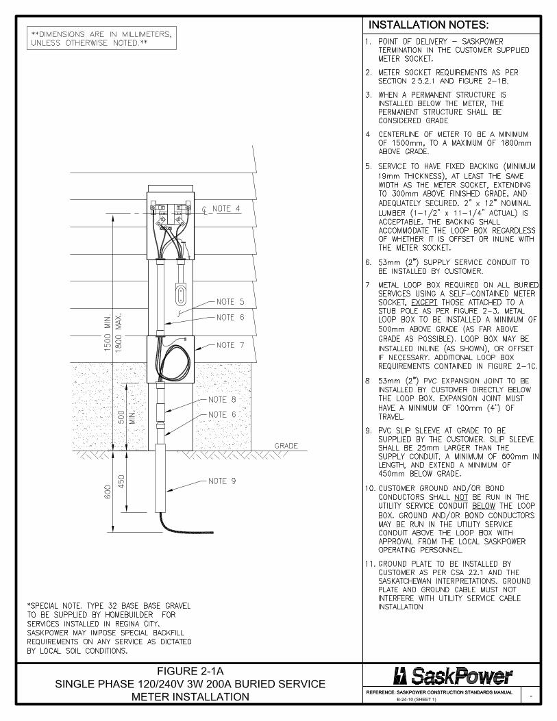
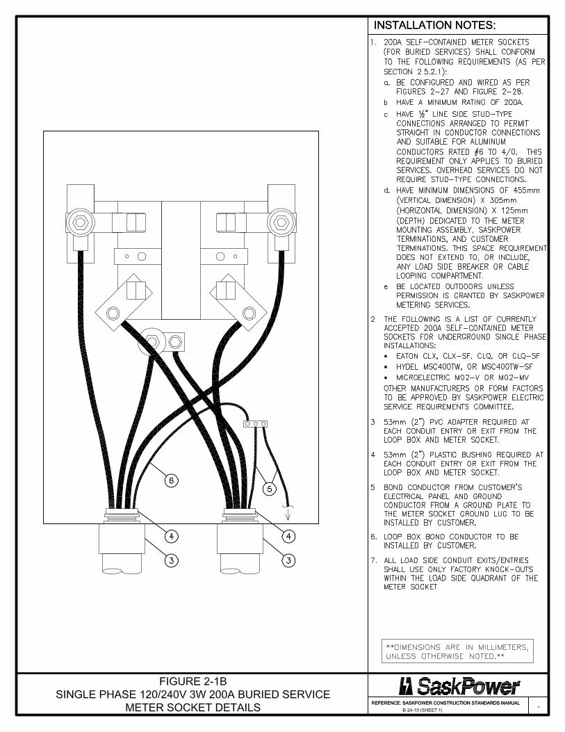

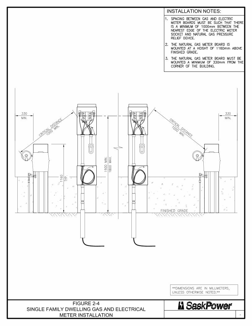
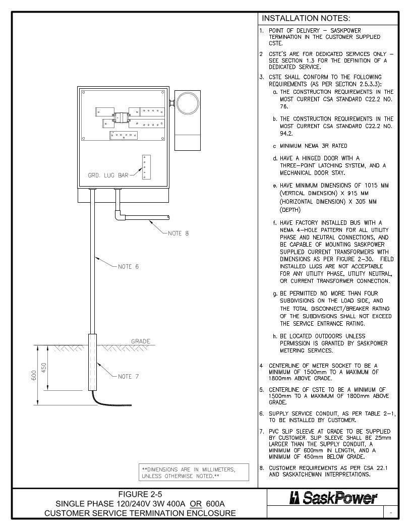
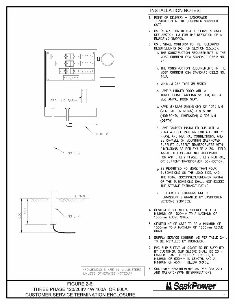
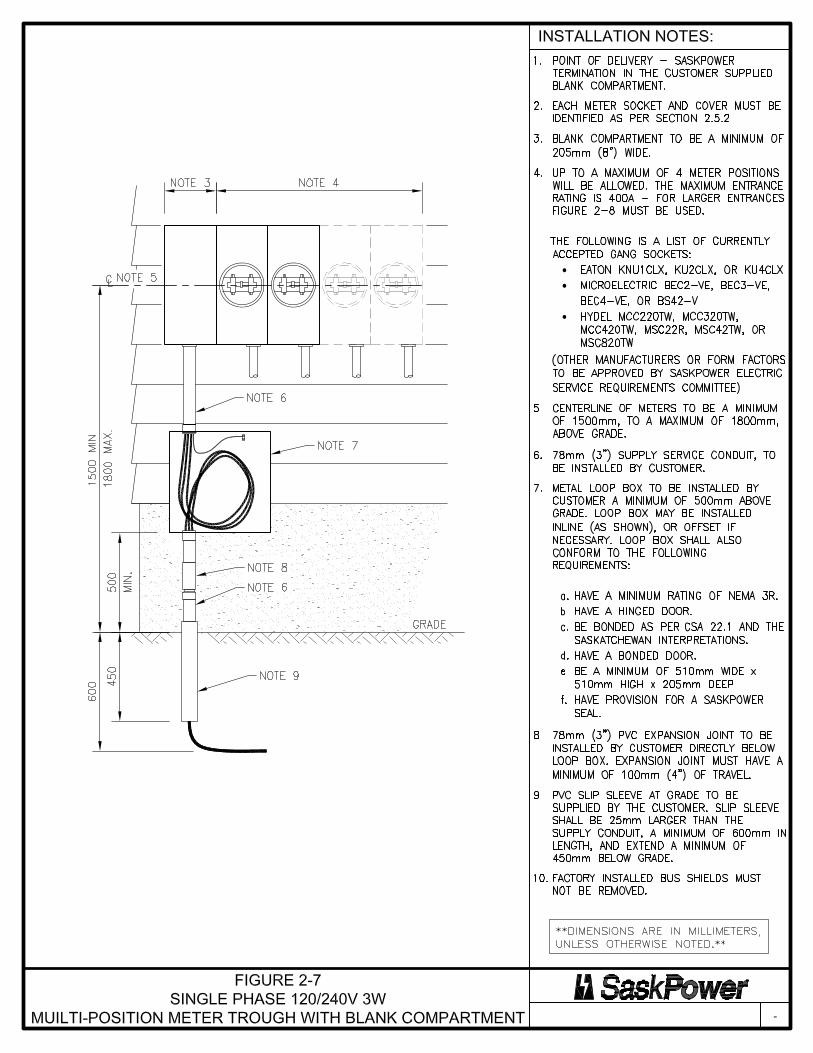
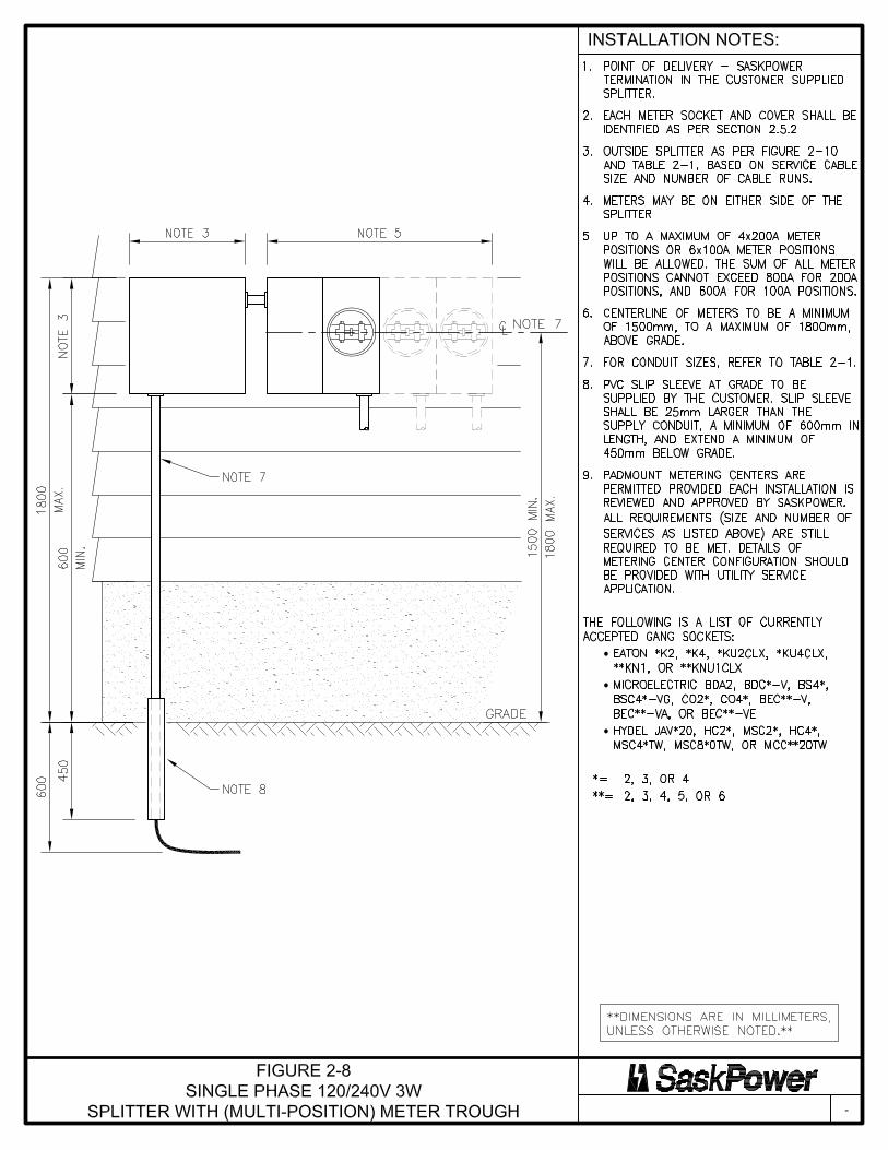

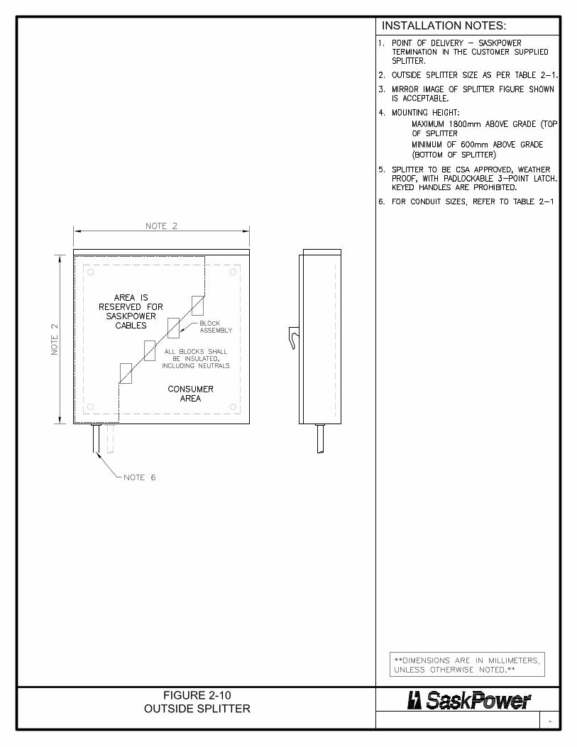
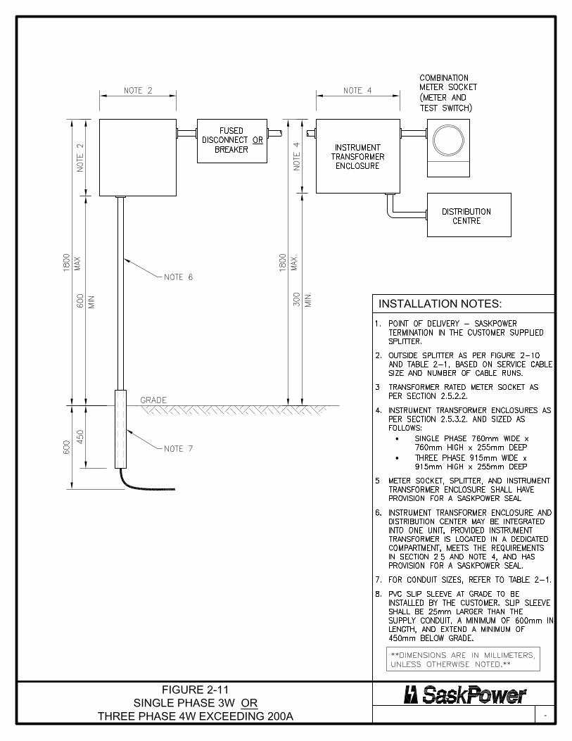

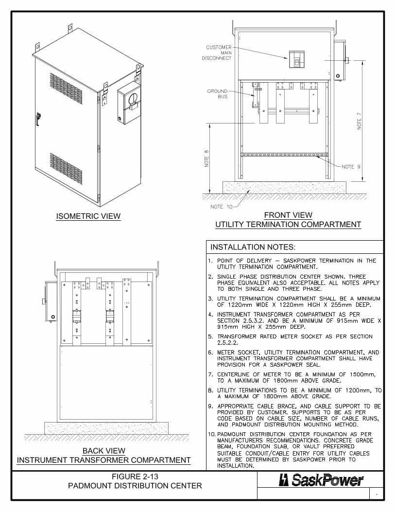

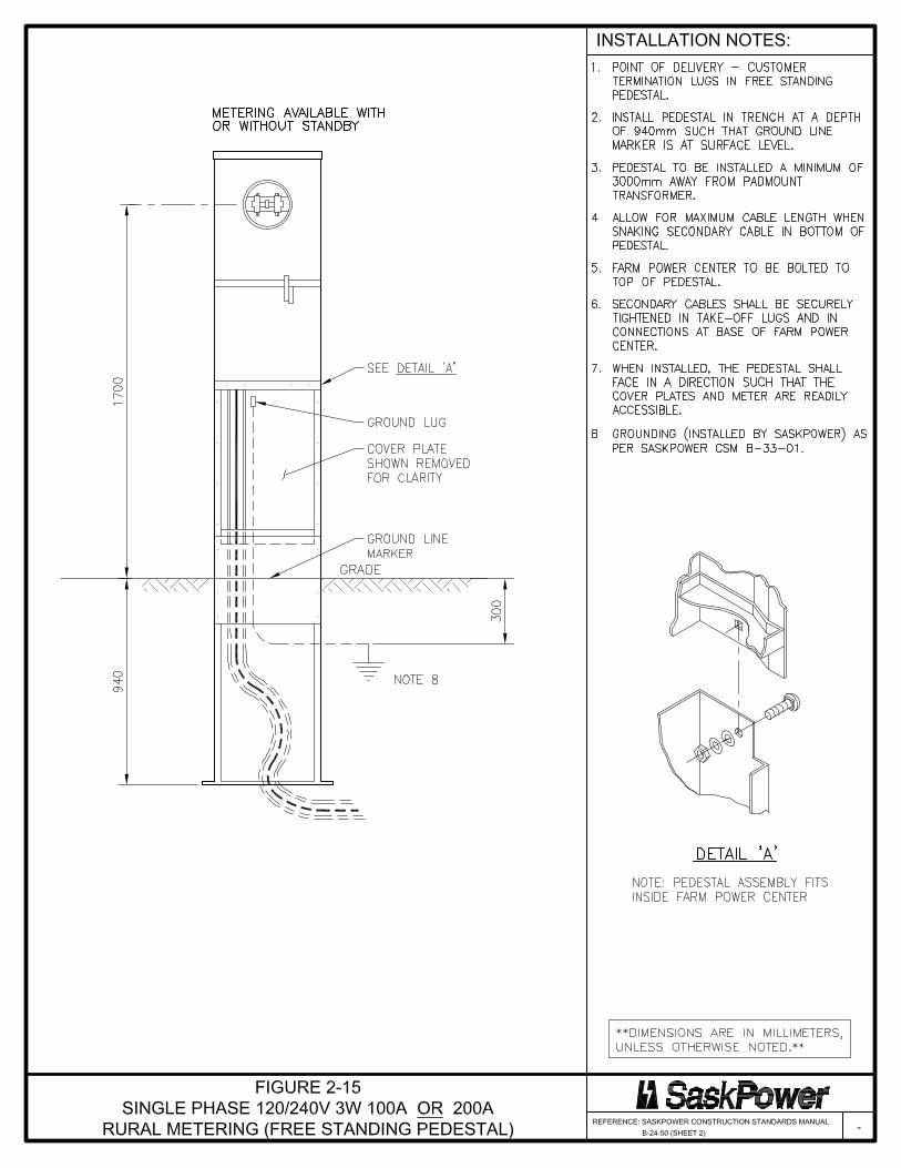
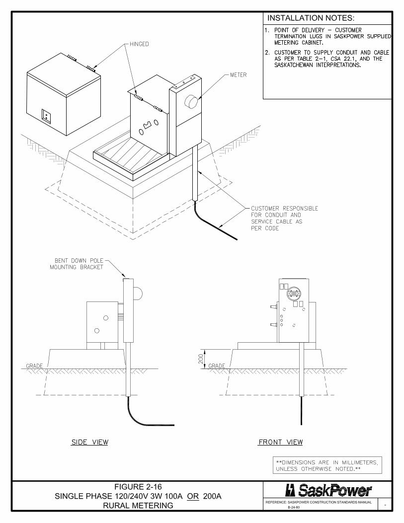
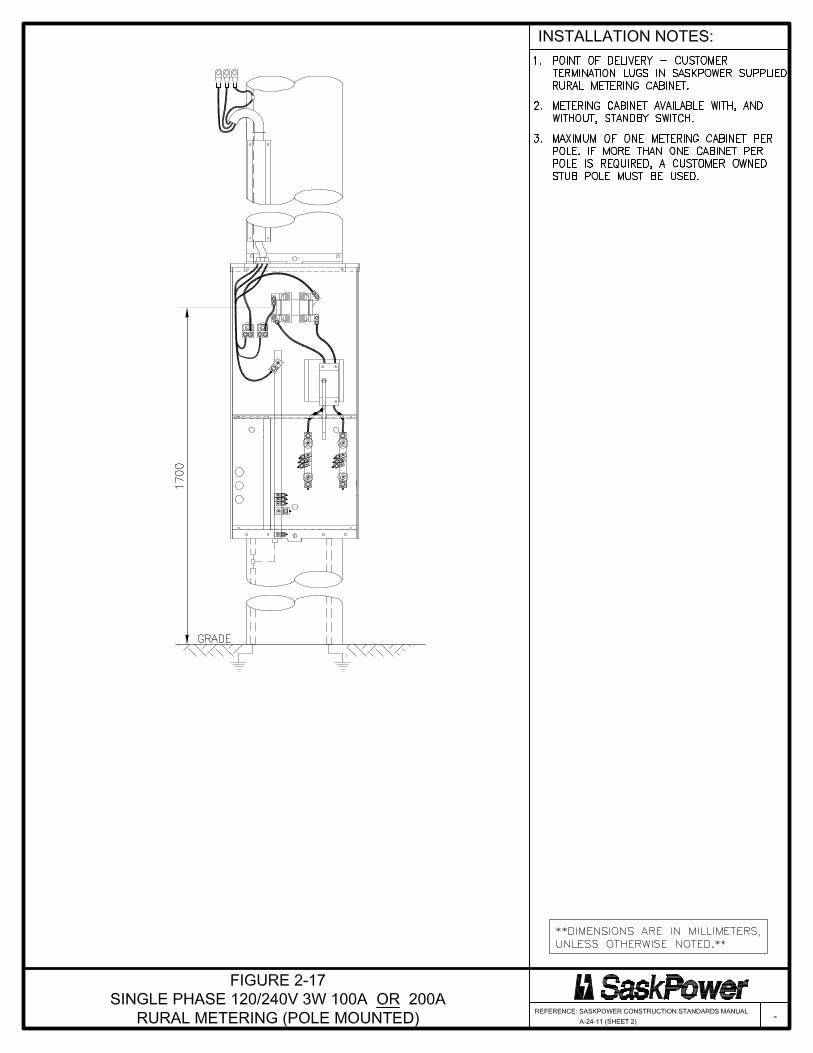
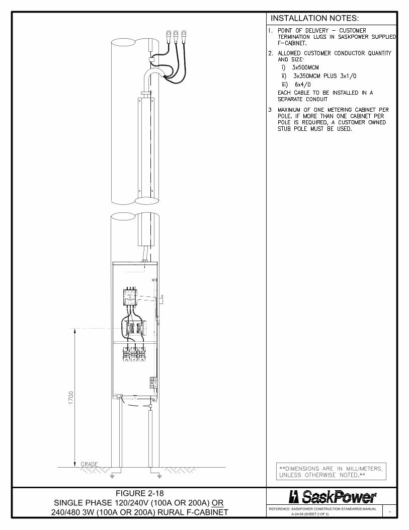

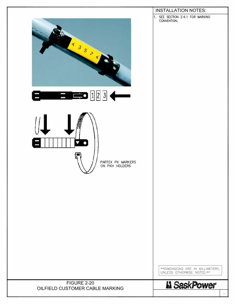
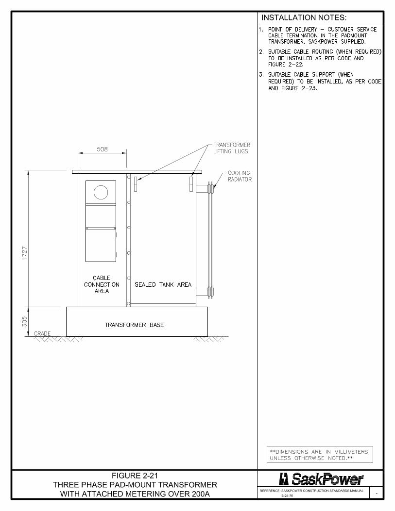
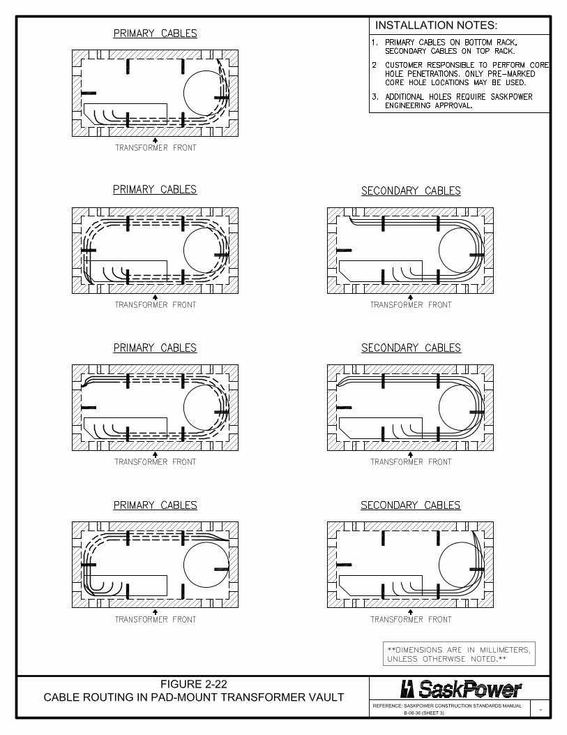


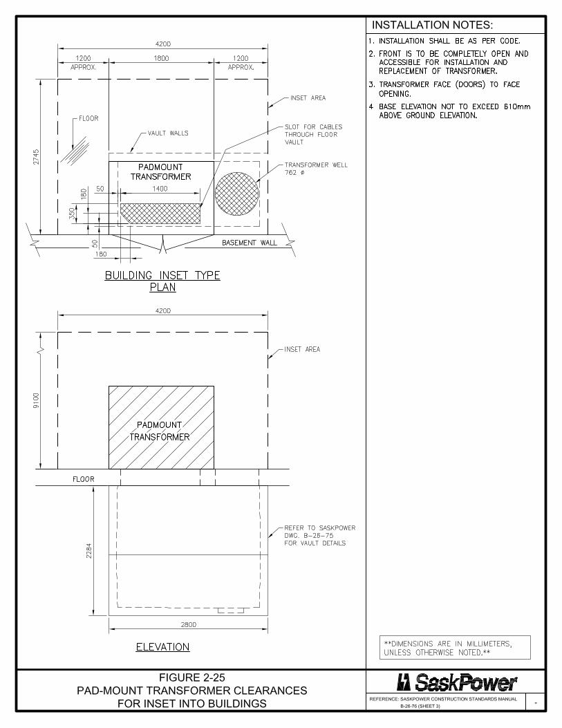

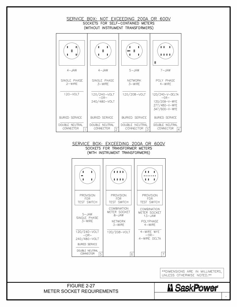
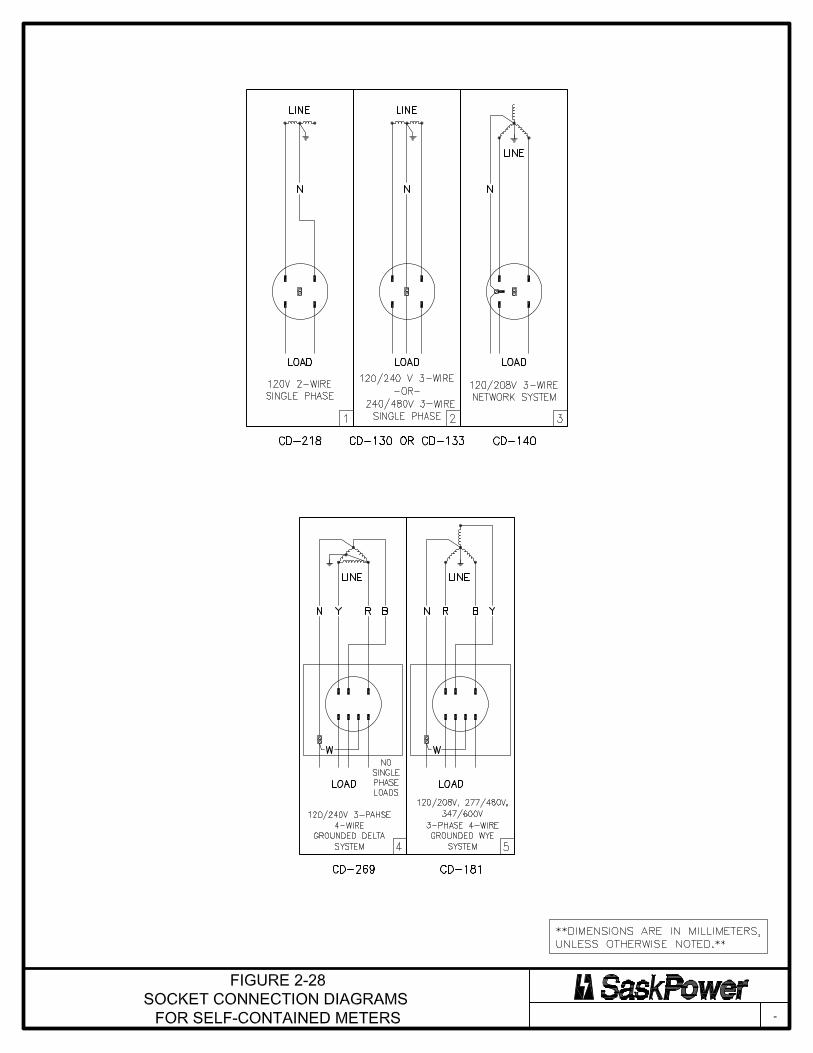
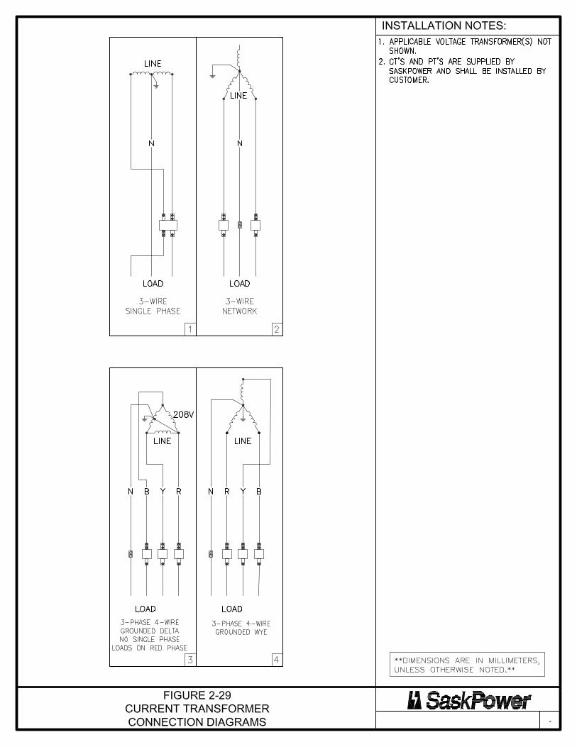
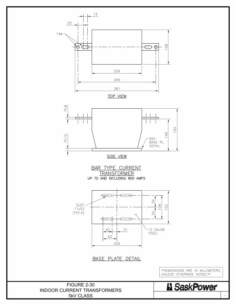
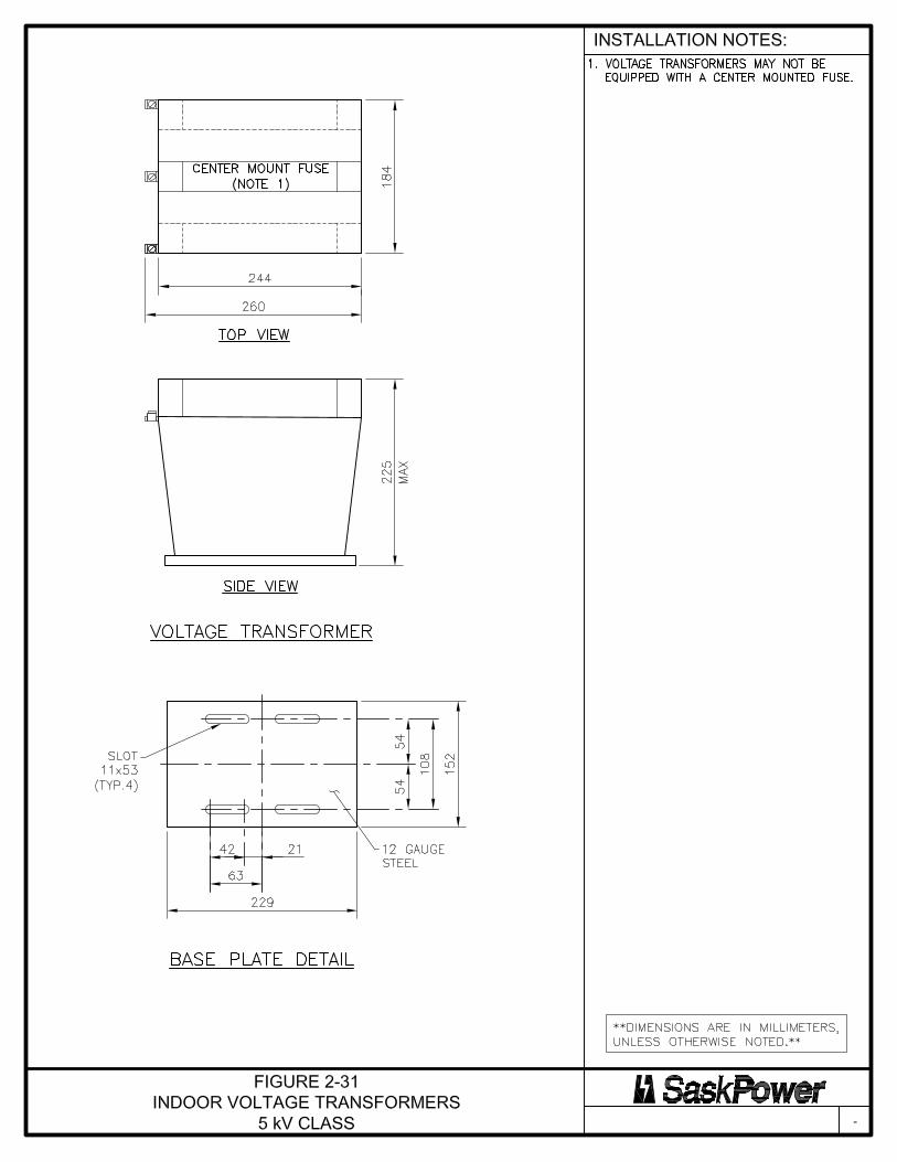
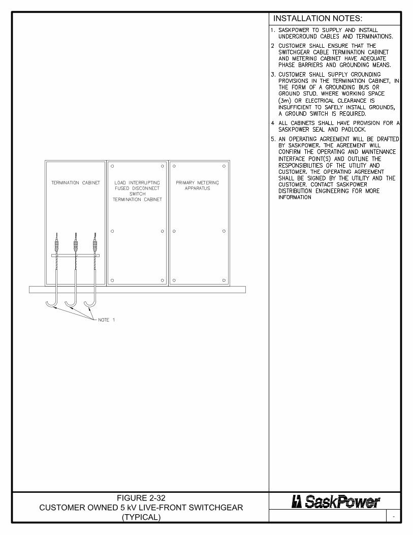

SaskPower Electric Service Requirements Revision 2 March 19, 2021
68
2.7 Tables for Services up to and Including 5 kV
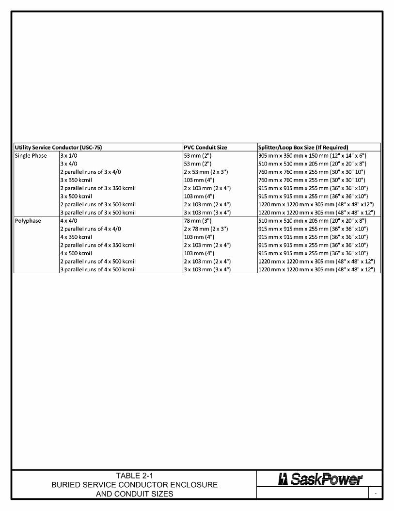

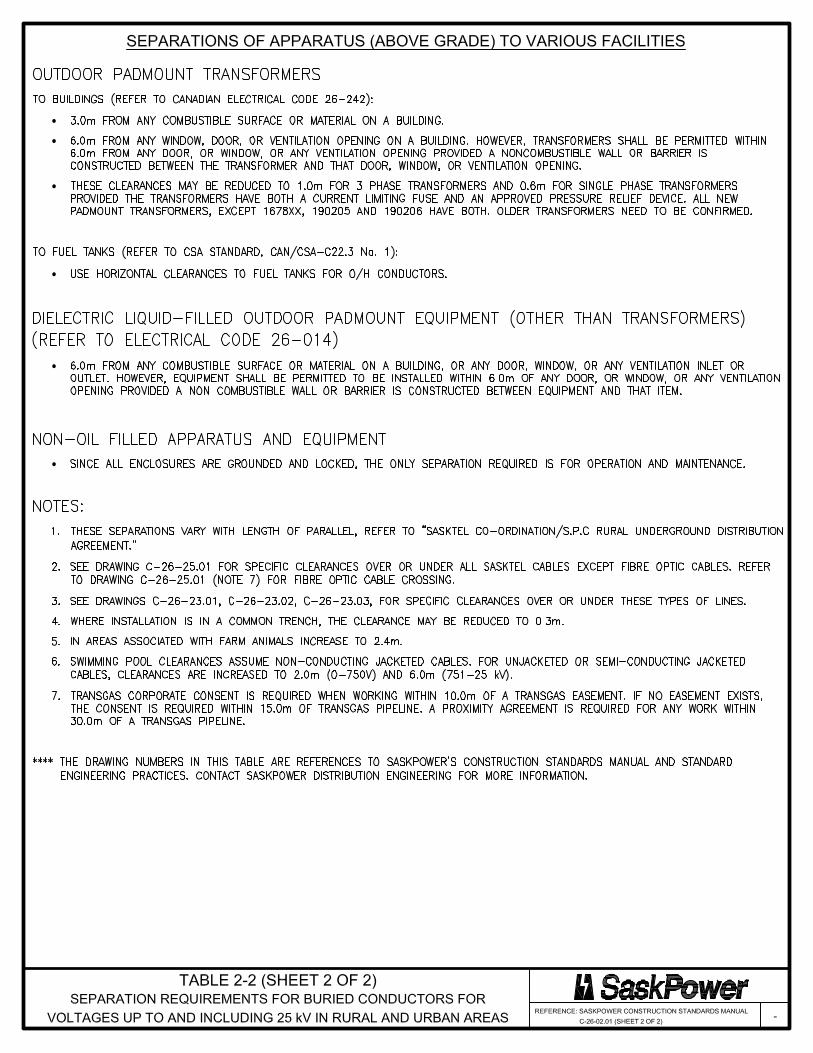
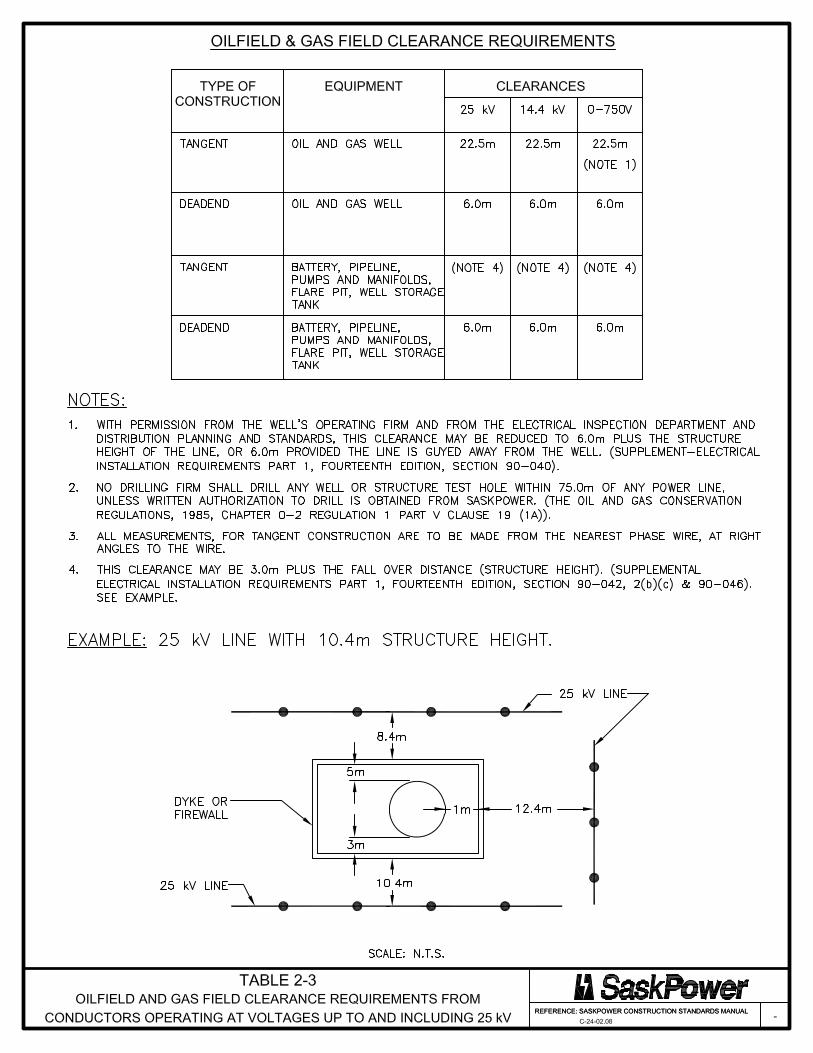
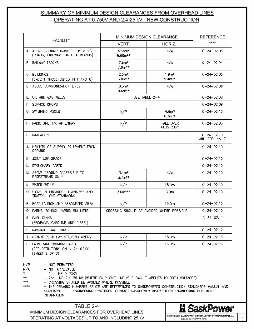

SaskPower Electric Service Requirements Revision 2 March 19, 2021
74
3. SaskPower System Characteristics and Power Quality Requirements for Customer Loads
3.1 Power Quality
“Any deviation to the magnitude or frequency of the ideal sinusoidal voltage waveform can be regarded as a Power Quality Disturbance” (Dr. Gerald L. Park, Michigan State University). SaskPower is concerned about power quality disturbances. SaskPower recognizes that power quality disturbances can cause problems for the operation of Customer equipment. Power quality disturbances can also increase the energy losses on SaskPower’s system and lead to the damage or mal operation of SaskPower equipment. Deviations of the voltage waveform on SaskPower’s system can be caused by disturbances originating on SaskPower’s system, and by the operation of Customer owned equipment. SaskPower attempts to minimize the magnitude, frequency and duration of disturbances originating on the power system when designing its facilities. SaskPower has also set out requirements that must be met in terms of limiting the effect of power quality disturbances on SaskPower’s system caused by the operation of Customer equipment. This section sets out the requirements that Customers must meet to limit their impact on SaskPower’s system and on other Customers. It also sets out some guidelines as to the types of disturbances that the Customer can expect to be exposed to as a result of being connected to SaskPower’s system. The Customer should take into consideration these disturbances when evaluating their supply requirements. This section does not constitute a guide or design handbook for power quality. Customers should engage the services of individuals qualified to provide design and consulting services to assist them in addressing their power quality concerns. Customers may also contact SaskPower to discuss the characteristics of the supply from SaskPower and their power quality requirements.
3.2 Characteristics of the SaskPower System
The following sets out the characteristics of the SaskPower system. Customers should take these characteristics into consideration when evaluating the reliability and power quality requirements for their electrical supply.
3.2.1 Frequency and Frequency Variation The nominal frequency of the SaskPower system is 60 Hz. During normal operation, frequency is maintained within + 0.02 Hz of 60 Hz. Frequency excursions outside of this range will occur during disturbances on the power system.
3.2.2 Normal Voltage Variation The supply voltages at which power is delivered to the Customer vary from nominal for a number of reasons including load variation and changes in conditions on the power system. As long as the voltage remains with the ranges defined in Section 3.2.2, SaskPower will not take any action to correct the voltage. During extreme operating conditions, the voltage may temporarily exceed the voltage ranges defined in Section 3.2.2. SaskPower will take action to correct sustained voltage variations during extreme conditions. The speed of the corrective
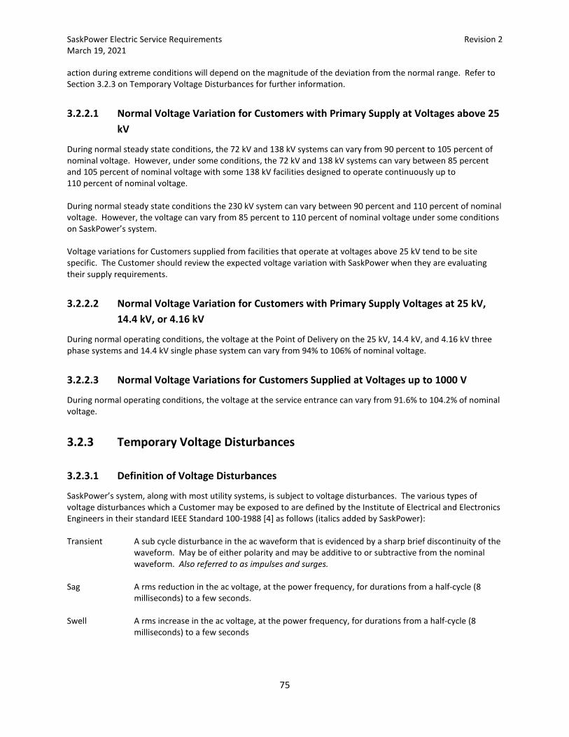
SaskPower Electric Service Requirements Revision 2 March 19, 2021
75
action during extreme conditions will depend on the magnitude of the deviation from the normal range. Refer to Section 3.2.3 on Temporary Voltage Disturbances for further information.
3.2.2.1 Normal Voltage Variation for Customers with Primary Supply at Voltages above 25 kV
During normal steady state conditions, the 72 kV and 138 kV systems can vary from 90 percent to 105 percent of nominal voltage. However, under some conditions, the 72 kV and 138 kV systems can vary between 85 percent and 105 percent of nominal voltage with some 138 kV facilities designed to operate continuously up to 110 percent of nominal voltage. During normal steady state conditions the 230 kV system can vary between 90 percent and 110 percent of nominal voltage. However, the voltage can vary from 85 percent to 110 percent of nominal voltage under some conditions on SaskPower’s system. Voltage variations for Customers supplied from facilities that operate at voltages above 25 kV tend to be site specific. The Customer should review the expected voltage variation with SaskPower when they are evaluating their supply requirements.
3.2.2.2 Normal Voltage Variation for Customers with Primary Supply Voltages at 25 kV, 14.4 kV, or 4.16 kV
During normal operating conditions, the voltage at the Point of Delivery on the 25 kV, 14.4 kV, and 4.16 kV three phase systems and 14.4 kV single phase system can vary from 94% to 106% of nominal voltage.
3.2.2.3 Normal Voltage Variations for Customers Supplied at Voltages up to 1000 V
During normal operating conditions, the voltage at the service entrance can vary from 91.6% to 104.2% of nominal voltage.
3.2.3 Temporary Voltage Disturbances
3.2.3.1 Definition of Voltage Disturbances
SaskPower’s system, along with most utility systems, is subject to voltage disturbances. The various types of voltage disturbances which a Customer may be exposed to are defined by the Institute of Electrical and Electronics Engineers in their standard IEEE Standard 100-1988 [4] as follows (italics added by SaskPower): Transient A sub cycle disturbance in the ac waveform that is evidenced by a sharp brief discontinuity of the
waveform. May be of either polarity and may be additive to or subtractive from the nominal waveform. Also referred to as impulses and surges.
Sag A rms reduction in the ac voltage, at the power frequency, for durations from a half-cycle (8
milliseconds) to a few seconds. Swell A rms increase in the ac voltage, at the power frequency, for durations from a half-cycle (8
milliseconds) to a few seconds

SaskPower Electric Service Requirements Revision 2 March 19, 2021
76
Over voltage A rms increase in the ac voltage, at the power frequency, for durations greater than a few seconds.
Under voltage A rms decrease in the ac voltage, at the power frequency, for durations greater than a few
seconds. Interruption The complete loss of voltage for a period of time. Also referred to as an outage. In the case of
SaskPower’s system, interruptions may be momentary (refer to Section 3.2.6 on auto reclose) or sustained.
3.2.3.2 Frequency of Voltage Disturbances
In 1990, the Canadian Electrical Association (CEA) sponsored a survey of power quality at 550 sites across Canada for a 25-day period. The results of the study are presented in the Canadian Electrical Association report CEA National Power Quality Survey (Report # 220 D 711A). The survey results indicated that voltage disturbances are a normal occurrence for most Customers. Table 3-1 provides a summary of the type and frequency of disturbances that were experienced by Customers during the CEA survey.
Table 3-1: CEA Power Quality Survey Results
Type of Disturbance Percentage of Sites Which Recorded This Type of Disturbance
Average Number of This Type of
Disturbance per Month
Transient 75 % 184 Wave shape (1) 50 % 4 Swell (1) 77 % 176 Sag (1) 74 % 29 Interruption 23 % 1
Note (1): The National Power Quality Survey did not use terms consistent with the IEEE
Standard 100-1988 [4] standard. Wave shape is a term defined in the survey and means a waveform distortion lasting 1 ms to 80 ms. The survey defined sags and swells as lasting from 80 ms to 10 seconds.
The results of the CEA National Power Quality Survey indicate that Customers should expect to be exposed to voltage disturbances. As a general guideline for Customers supplied from SaskPower’s system, those Customers with primary supply voltages above 25 kV may expect to be exposed to fewer voltage disturbance conditions than those Customers with primary supply voltages at 25 kV or lower. However, the magnitude of the voltage disturbance experienced may be greater than for those connected at 25 kV or lower.
3.2.3.3 Transient Voltages
Transients can be caused by such phenomena as lightning strikes, some types of faults, and the switching of some types of Customer loads. The majority of voltage transients on Customer premises are low energy and arise from the operation of Customer owned equipment, primarily load switching. These low energy transients generally do not result in Customer equipment damage. SaskPower follows normal utility practices in dealing with voltage transients originating on its own power system. This involves the application of surge arresters and the specification of insulation levels that are high enough to allow its own equipment to withstand most expected voltage transients without damage. SaskPower’s practices will not eliminate voltage transients from originating on SaskPower’s system. The Customer must insure that the
SaskPower Electric Service Requirements Revision 2 March 19, 2021
77
insulation levels, and protective apparatus (surge arresters, etc.) employed in their facilities are adequate to allow their facilities to withstand the magnitude and energy of typical voltage transient which originate on SaskPower’s power system. Canadian Standards Association Guides CAN/CSA C71-1-99 and C71-2-98 set out the principles and practice for insulation coordination on three phase ac power systems having a nominal voltage above 1000 volts.
3.2.3.4 Voltage Sags and Swells
Voltage sags can be caused by, amongst other conditions, faults on the power system, and the starting of Customer owned motors. Voltage swells can be caused by voltage recovery following the clearing of a fault on the system, and the healthy phase voltage rise during single phase to ground faults (applies to single phase Customers). Because of their short duration, SaskPower takes limited action to correct voltage sags and swells. SaskPower attempts to control voltage sags and swells caused by the operation of Customer loads by setting limits on the permissible voltage deviation caused by normal operation of Customer equipment. These limits are set out in Section 3.3. Voltage sags and swells caused by faults on the system will normally be cleared in 3 seconds or less by protective equipment which isolates the faulted apparatus. For very large changes in voltage that fall outside of the normal voltage variation range described in Section 3.2.2, supply to Customer load supplied at voltages of 72 kV or lower may be interrupted by SaskPower to limit damage to Customer loads. SaskPower applies limited over and under voltage protection systems on its 138 kV and 230 kV systems. However, these systems are designed to protect SaskPower’s facilities and may not provide protection for Customer apparatus. In areas of low Customer density, Customers are typically supplied from long distribution feeders. The probability of a feeder experiencing a fault is directly related to its length. As a result, Customers supplied from longer feeders can be exposed to a relatively high number of voltage swells caused by healthy phase voltage rise due to faults on adjacent phase conductors, or voltage sags caused by the presence of faults on adjacent feeders or adjacent phases. Voltage sags and swells caused by system faults will vary in magnitude depending on the proximity of the fault to the Customer. Voltage sags and swells caused by faults are normally cleared in 1 second but may last up to 3 seconds in some cases. The magnitude of the voltage swell caused by healthy-phase voltage rise can be in the order of 30%. Some Customer apparatus may be subject to damage from voltage sags or swells. The Customer should give consideration to isolating this apparatus by applying the appropriate protection systems. Customer owned equipment, particularly process controls, may be susceptible to mal-operation during voltage sags and swells. If the consequences of mal-operation are significant, the Customer should give consideration to isolating this equipment by applying power conditioning equipment.
3.2.3.5 Over and under Voltage Conditions
Under voltages are normally caused by the sudden application of a large load on the system or the unplanned outage of one of SaskPower’s transmission facilities. Over voltages can be caused by the loss or reduction of Customer load, or the switching of SaskPower facilities. SaskPower designs its 138 kV and 230 kV systems to operate within the range specified in Section 3.2.2.1. However, depending on the location, it may not take corrective action if the voltage falls outside of this range. SaskPower applies over and under voltage protection systems on its 138 kV and 230 kV systems. However, these systems are designed to protect SaskPower’s facilities and may not provide protection for Customer apparatus. For Customer load supplied at 72 kV or lower, under and over voltage conditions which result from changes in load are normally corrected through the operation of voltage regulation equipment on SaskPower’s system. Depending
SaskPower Electric Service Requirements Revision 2 March 19, 2021
78
on the location in SaskPower’s system, voltage regulator action can take from 15 seconds to 90 seconds before it starts to correct the condition. For very large changes in voltage that fall outside of the normal voltage variation range described in 3.2.2, supply to Customer load supplied at 72 kV or lower may be interrupted by SaskPower to limit damage to Customer loads. In areas of low Customer density, Customers are typically supplied from long distribution feeders. Long feeders require the use of series connected voltage regulators to maintain a satisfactory voltage profile along the feeder. In order to provide satisfactory operation, these voltage regulators are time coordinated, with the last regulator on a feeder being the slowest. Customers supplied from such systems can be exposed to a relatively high number of under and over voltage conditions due to the long feeders and use of time-coordinated in-line voltage regulators. Some Customer apparatus may be subject to damage from over and under voltage conditions. The Customer should give consideration to isolating this apparatus by applying the appropriate protection systems. Customer owned equipment, particularly process controls, may be susceptible to mal-operation during over and under voltage conditions. If the consequences of mal-operation are significant, the Customer should give consideration to isolating this equipment by applying power conditioning equipment.
3.2.3.6 Interruptions
As is normal practice in the utility industry, SaskPower cannot guarantee interruption free service. Customers with processes that are sensitive to service interruptions should evaluate their requirements for uninterruptible power supplies or back-up power. Customers with primary supply at voltages that are 25 kV or lower are supplied from SaskPower’s distribution system. As is normal practice in the utility industry, SaskPower’s distribution system utilizes unshielded construction with insulation levels appropriate to withstanding expected power frequency voltages. As such, direct lightning strikes to distribution power lines, or nearby ground lightning strokes will usually result in a flash over of the insulators on the power line, resulting in an interruption by SaskPower’s protection systems. If the fault is temporary, service may be restored by SaskPower’s auto reclose system. In areas of low Customer density, Customers are typically supplied from long distribution feeders. The probability of a feeder experiencing a fault is directly related to its length. As a result, Customers in these areas can be exposed to a relatively high number of power interruptions, whether they are momentary (successful auto reclose), or sustained (permanent fault).
3.2.4 System Voltage Unbalance
3.2.4.1 Definition of Voltage Unbalance
Voltage unbalance, as derived from NEMA MG1-14.34, is defined as follows:
( )voltagephasetophaseaverage
voltagephasetophaseaveragefromdeviationgreatestUnbalance ×=
100(%)
Voltage unbalance is a concern for Customers with three-phase services. Voltage unbalance has an adverse effect on the operation of three-phase motors. For induction motors, these effects include; hotter than normal operation, reduced locked-rotor torque, reduced breakdown torque, and reduced full load speed. Customers should take into consideration the potential for voltage unbalance and size their motors using the appropriate derating factor. SaskPower will not be responsible for damage to Customer facilities due to voltage unbalance.
SaskPower Electric Service Requirements Revision 2 March 19, 2021
79
3.2.4.2 Voltage Unbalance for Customers with Primary Supply at Voltages above 25 kV
Voltage unbalance on Customer loads supplied from SaskPower facilities, which operate at voltages above 25 kV, is normally less than 1%. During faults on SaskPower’s system and within single pole reclosing cycles, the momentary unbalance may be greater than defined above.
3.2.4.3 Voltage Unbalance for Customers with Primary Supply at Voltages 25 kV and Below
Voltage unbalance should be expected on Customer loads supplied from SaskPower facilities at 25 kV and below. During normal steady state operation, voltage unbalance is normally less than 3%. In some rural locations, unbalance may be higher. The Customer should check with SaskPower to obtain site-specific details. During faults on SaskPower’s system and within single pole reclosing cycles, the momentary unbalance may be significantly greater than defined above. Refer to Section 3.2.6 for further details on faults and reclosing.
3.2.5 Harmonic Voltage Distortion Harmonic voltage distortion is the distortion of the voltage waveform from a true sinusoidal shape. It is normally caused by non-linear Customer loads which draw harmonic currents (currents which are multiples of the fundamental frequency) from SaskPower’s system. Harmonic voltage distortion can cause problems for SaskPower and Customers such as; equipment overloading, increased energy losses, premature failure, mal operation and interference with other equipment. A small amount of background harmonic voltage distortion (< 1 % total harmonic distortion) is always present on SaskPower’s system. In certain locations there may be higher levels of harmonic voltage distortion. Higher levels of harmonic voltage distortion are normally caused by the presence of Customer owned equipment with nonlinear load characteristics. SaskPower attempts to mitigate the impact of Customer owned equipment by setting limits on the flow of harmonic currents caused by Customer equipment. These limits are set out in Section 3.4. SaskPower’s objective is to maintain the level of voltage distortion at the Customer’s Point of Delivery at levels within the values specified in Table 3-2.
Table 3-2: SaskPower’s Voltage Distortion Guidelines
Service Voltage ID – Individual Voltage Distortion (% of fundamental frequency voltage)
THD - Total Voltage Distortion
(% of fundamental frequency voltage)
25 kV and below 3.0 5.0 72 kV and 138 kV 1.5 2.5
230 kV 1.0 1.5 For short periods of time, generally 60 seconds or less, these values may be exceeded by 50%.
3.2.6 Single Phase Tripping and Automatic Reclosing SaskPower applies automatic reclosing on its 14.4 kV single phase system and single phase tripping with reclosing on many of the interrupting devices (circuit breakers) on its 25 kV, 72 kV, 138 kV and 230 kV systems. Automatic reclose is a system that automatically attempts to restore service on a tripped power line following a transient fault such as may be caused by a lightning induced flashover. Restoration may be attempted very quickly after
SaskPower Electric Service Requirements Revision 2 March 19, 2021
80
tripping of the power line (within 0.5 seconds). Single phase tripping interrupts only the faulted phase in the event of a single-phase fault on the power line (the line will subsequently trip on all three phases if the fault is permanent). Single phase tripping will cause unbalanced voltages during the disturbance. Automatic reclose, whether it is single phase or three phase, will result in shock loading during the trip / reclose cycle. Customers with large motors, many motors, or other sensitive loads, must take into consideration SaskPower’s reclose practices when assessing their supply requirements.
3.2.6.1 Customers with Primary Supply at Voltages above 25 kV
On most of SaskPower’s facilities that operate at voltages above 25 kV, SaskPower utilizes high-speed automatic reclose. Automatic reclose normally is applied for single line to ground faults only and is normally blocked for multi-phase faults; however, some older installations may not block for all multi-phase faults. Most of the 230 kV transmission lines utilize single-phase tripping and high-speed reclose. The dead time for three-phase automatic reclose is about 30 cycles (0.5 sec) and for single-phase automatic reclose, it is about 45 cycles (0.750 sec). Only one attempt is made to automatically reclose following a fault. At locations where automatic reclose is applied at the 72 kV level, the line dead time is greater than one second. The Customer should check with SaskPower to confirm whether they will be subject to auto reclose.
3.2.6.2 Customers with Primary Supply Voltages at 25 kV and Below
Customers in rural environments will normally be subject to automatic reclose operations. The SaskPower rural 25 kV three phase and 14.4 kV single phase Distribution System utilizes automatic-reclose which will make multiple high speed attempts to clear non-permanent faults. The interruption time during each reclose cycle can vary up to 5 seconds. Interrupting devices may trip a single phase or all three phases, depending on the application. In the event of a permanent fault, all three phases of the interrupting device will be tripped regardless of whether it is a single phase or three-phase fault. SaskPower normally applies auto reclose in urban environments. The Customer should check with SaskPower to confirm whether they will be subject to auto reclose.
3.2.7 System Fault Levels and System Impedences Faults within Customer facilities will be subject to fault currents from SaskPower’s system. The fault current contribution from SaskPower’s system is influenced by numerous factors, including Customer location on SaskPower’s system, system generation pattern, and service voltage. Future fault levels will also be influenced by system expansion. Customers must design their facilities such that they are able to withstand the mechanical forces that result from these fault currents and that they have interrupting devices capable of interrupting these fault currents. Customers should ensure that their designs have a reasonable margin to accommodate future increases in fault level. Customers are responsible to ensure that their existing facilities are capable of withstanding existing and future fault current contributions from SaskPower’s system. The Customer is responsible for all costs associated with accommodating future changes in SaskPower’s fault levels and system impedance. The expected fault contribution from SaskPower’s system along with the SaskPower system impedance for a site can be obtained from SaskPower.
SaskPower Electric Service Requirements Revision 2 March 19, 2021
81
3.3 Limits on Voltage Disturbances Caused by Customer Loads
SaskPower sets limits on the maximum voltage fluctuation and voltage waveform notching caused on its system by the normal operation of Customer equipment. Customer induced voltage fluctuation is a variation of the rms voltage which occurs as a result of variations in a Customer’s load. Voltage notching typically results from the operation of rectifiers associated with variable speed drives. Normal operation would include such things as the starting and stopping of motors, quickly changing loads associated with a variable process, electric furnace operation, pulsing loads such as reciprocating compressors or electric arc welding processes. The Customer is responsible for ensuring that the design and operation of the Customer’s electrical facilities connected to SaskPower’s system complies with SaskPower's limits on voltage disturbances. The detailed engineering work and cost associated with mitigating Customer generated voltage disturbances is the responsibility of the Customer. Acceptance for service is subject to a compliance test carried out at SaskPower's discretion by SaskPower staff. SaskPower will not review a design for the purpose of pre acceptance and waiving a compliance test. The Point of Delivery is the point at which voltage fluctuations and commutation notching caused by the Customer load are evaluated for compliance with the limits set by SaskPower. The limits on the magnitude and rate of voltage disturbances are specified in Section 3.3.1 through Section 3.3.4. These are limits for the Customer’s site. This may require that the Customer set lower limits on individual devices within the Customer’s premises so that the limits for the overall site are satisfied.
3.3.1 Infrequent Voltage Fluctuations (up to Once per Day) Caused by Customer Equipment
3.3.1.1 Limit on Infrequent Voltage Fluctuations Caused by Customer Equipment
Customers with apparatus that causes infrequent voltage fluctuations (once per day or less), shall limit the magnitude of the voltage fluctuation to 8% or less.
3.3.1.2 Definition of Magnitude of Voltage Fluctuations
For the purpose of evaluating compliance with the limits specified in Section 3.3.1.1 and Section 3.3.2.1, the magnitude of the voltage fluctuation in percent is defined as:
( )( ) 100
Voltage eDisturbanc PreVoltage eDisturbanc
×= ofValueAbsolutenFluctuatioVoltage
The magnitude of the Pre Disturbance and Disturbance voltage shall be the rms magnitude of the 60 Hz sinusoidal voltage waveform. The Pre Disturbance Voltage and Disturbance Voltage are defined in Figure 3-1. Disturbance Voltages may represent an increase or decrease relative to the Pre Disturbance voltage. In the case of a negative voltage disturbance, if the voltage recovers to a value, which exceeds the Pre Disturbance voltage, the Disturbance Voltage shall be defined as the difference between the lowest voltage during the disturbance and the highest voltage during the recovery period. In the case of a positive voltage disturbance, if the voltage recovers to a value, which is less than the Pre Disturbance voltage, the Disturbance Voltage shall be defined as the difference between the highest voltage during the disturbance and the lowest voltage during the recovery period.
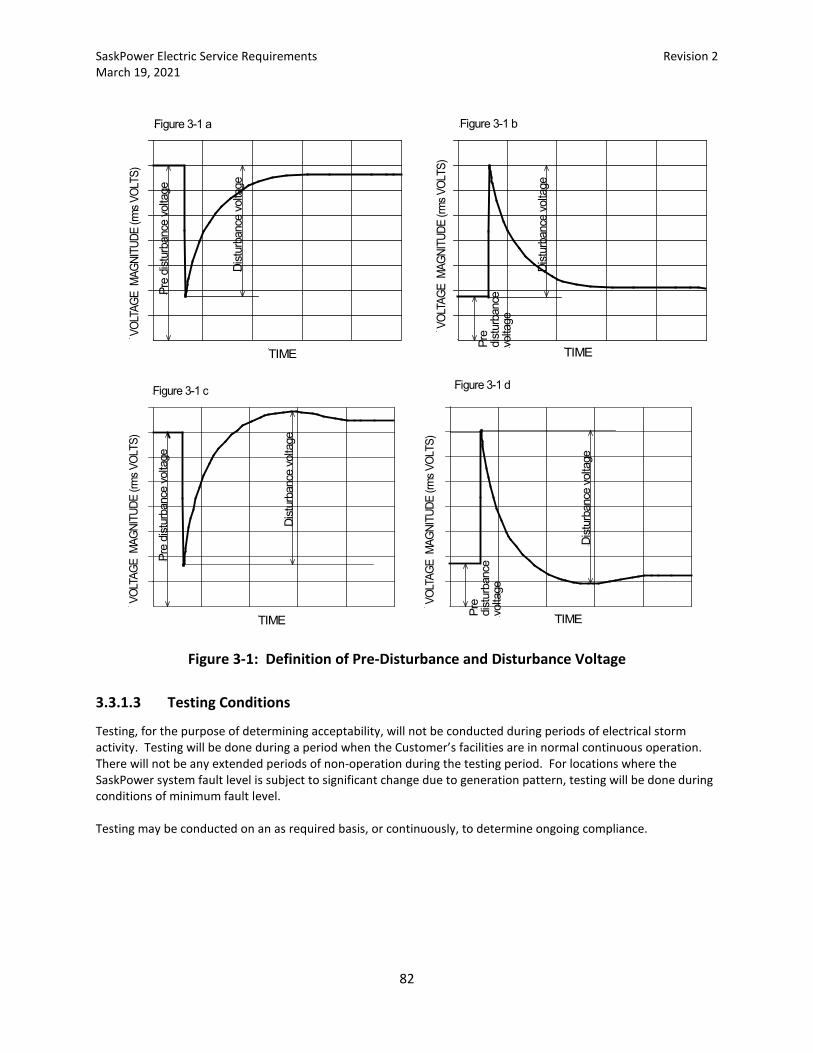
SaskPower Electric Service Requirements Revision 2 March 19, 2021
82
Figure 3-1: Definition of Pre-Disturbance and Disturbance Voltage
3.3.1.3 Testing Conditions
Testing, for the purpose of determining acceptability, will not be conducted during periods of electrical storm activity. Testing will be done during a period when the Customer’s facilities are in normal continuous operation. There will not be any extended periods of non-operation during the testing period. For locations where the SaskPower system fault level is subject to significant change due to generation pattern, testing will be done during conditions of minimum fault level.
Testing may be conducted on an as required basis, or continuously, to determine ongoing compliance.
TIME
VOL
TAGE
MAG
NITU
DE (r
ms V
OLTS
)
Pre
dist
urba
nce
volta
ge
Dist
urba
nce
volta
ge
VOL
TAGE
MAG
NITU
DE (r
ms V
OLTS
)
Pre
dist
urba
nce
volta
ge
Dist
urba
nce
volta
ge
Figure 3-1 a Figure 3-1 b
TIME
TIME
VOL
TAGE
MAG
NITU
DE (r
ms V
OLTS
)
Pre
dist
urba
nce
volta
ge
Dist
urba
nce
volta
ge
TIME
VOL
TAGE
MAG
NITU
DE (r
ms V
OLTS
)
Dist
urba
nce
volta
ge
Pre
dist
urba
nce
volta
ge
Figure 3-1 c Figure 3-1 d
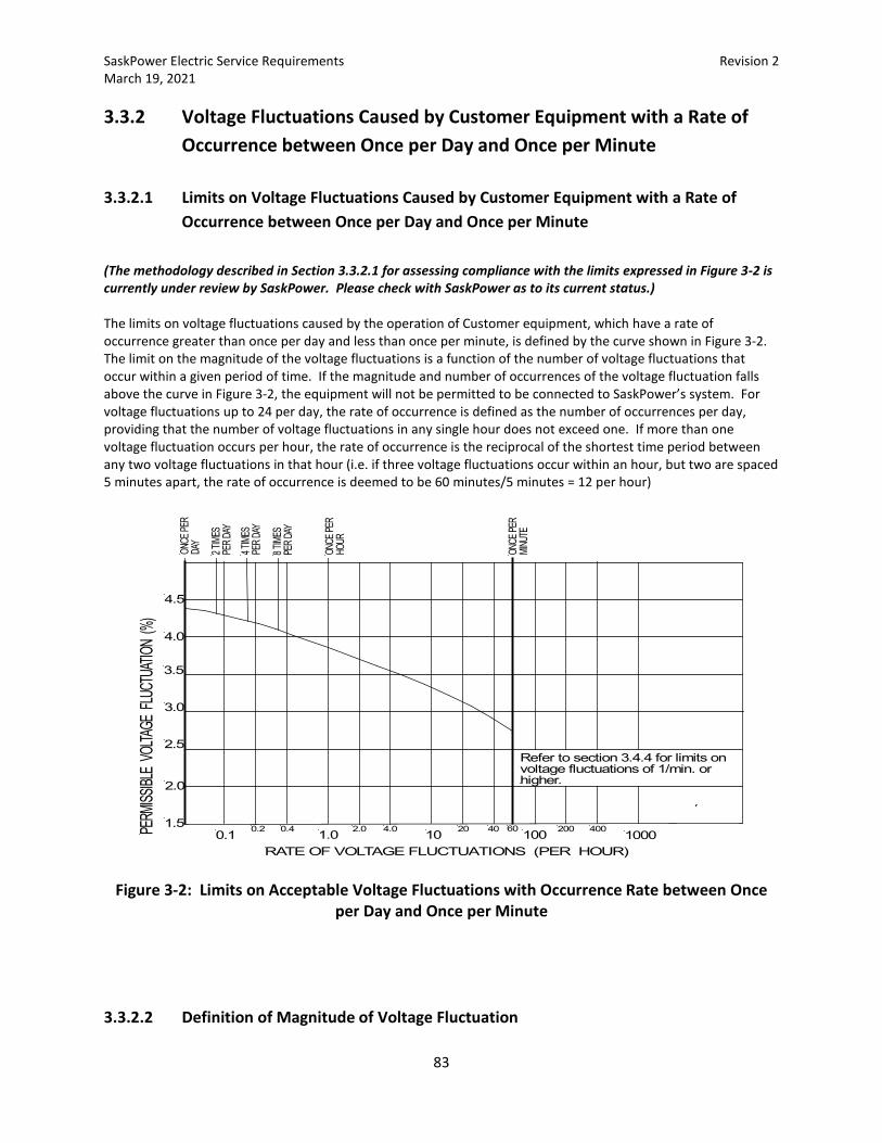
SaskPower Electric Service Requirements Revision 2 March 19, 2021
83
3.3.2 Voltage Fluctuations Caused by Customer Equipment with a Rate of Occurrence between Once per Day and Once per Minute
3.3.2.1 Limits on Voltage Fluctuations Caused by Customer Equipment with a Rate of Occurrence between Once per Day and Once per Minute
(The methodology described in Section 3.3.2.1 for assessing compliance with the limits expressed in Figure 3-2 is currently under review by SaskPower. Please check with SaskPower as to its current status.) The limits on voltage fluctuations caused by the operation of Customer equipment, which have a rate of occurrence greater than once per day and less than once per minute, is defined by the curve shown in Figure 3-2. The limit on the magnitude of the voltage fluctuations is a function of the number of voltage fluctuations that occur within a given period of time. If the magnitude and number of occurrences of the voltage fluctuation falls above the curve in Figure 3-2, the equipment will not be permitted to be connected to SaskPower’s system. For voltage fluctuations up to 24 per day, the rate of occurrence is defined as the number of occurrences per day, providing that the number of voltage fluctuations in any single hour does not exceed one. If more than one voltage fluctuation occurs per hour, the rate of occurrence is the reciprocal of the shortest time period between any two voltage fluctuations in that hour (i.e. if three voltage fluctuations occur within an hour, but two are spaced 5 minutes apart, the rate of occurrence is deemed to be 60 minutes/5 minutes = 12 per hour)
Figure 3-2: Limits on Acceptable Voltage Fluctuations with Occurrence Rate between Once
per Day and Once per Minute
3.3.2.2 Definition of Magnitude of Voltage Fluctuation
1.0 10 100 10000.1RATE OF VOLTAGE FLUCTUATIONS (PER HOUR)
2.0
3.0
2.5
3.5
4.0
4.5
1.5PERM
ISSIBL
E VO
LTAGE
FLU
CTUA
TION
(%)
0.2 0.4 2.0 4.0 20 40 60 200 400
2 TIM
ESPE
R DAY
4 TIM
ESPE
R DAY
8 TIM
ESPE
R DAY
ONCE
PER
DAY
ONCE
PER
MINU
TE
ONCE
PER
HOUR
Refer to section 3.4.4 for limits onvoltage fluctuations of 1/min. orhigher.

SaskPower Electric Service Requirements Revision 2 March 19, 2021
84
The definition of the magnitude of each individual voltage fluctuation is as defined in Section 3.3.1.2.
3.3.2.3 Testing Conditions
Testing, for the purpose of determining acceptability, will not be conducted during periods of electrical storm activity. Testing will be done during a period when the Customer’s facilities are in normal continuous operation. There will not be any extended periods of non-operation during the testing period. For locations where the SaskPower system fault level is subject to significant change due to generation pattern, testing will be done during conditions of minimum fault level. Testing may be conducted on an as required basis, or continuously, to determine ongoing compliance.
3.3.3 Voltage Fluctuations Caused by Customer Equipment with a Rate of Occurrence of Once per Minute or Higher (Flicker)
Voltage fluctuations with a rate of occurrence of once per minute or higher are typically referred to as flicker. Flicker is characterized as a disturbance voltage that modulates the amplitude of the supply voltage, as shown for example in Figure 3-3. Numerically, it is the root mean square (rms) value of the disturbance voltage expressed in percent of the average rms value of the supply voltage. The allowable level of flicker is limited because of its affect on other Customers. Primarily, voltage fluctuations affect the light level of incandescent and other types of lamps, which is perceived as a flickering sensation to the human eye. There are other apparatus, such as computers, instrumentation and communications equipment that can also be adversely affected by voltage fluctuations. The degree of objection to flicker has been found to be significant up to approximately 30 Hz (3600 voltage changes per minute).
120Vrms
0.35%=0.42Vrms0.35%
(not to scale)
Figure 3-3: Example of 60 Hz Supply Voltage Modulated by a 0.42 Vrms Rectangular Voltage Function
3.3.3.1 Limits for Flicker Caused by Customer Equipment with a Rate of Occurrence of Once per Minute up to 3600 per Minute
SaskPower Electric Service Requirements Revision 2 March 19, 2021
85
For Customer induced voltage fluctuations with a rate of 1 per minute up to 3600 per minute, SaskPower uses a measurement technique based upon the International Electrotechnical Commission Standard IEC 61000-4-15. SaskPower's limits for Customer induced voltage fluctuation with this rate of change are as follows: Pst95% = 1.0 Plt99% = 1.0 Where:
Pst95% is the level of the cumulative distribution of Pst, which is not exceeded for 95% of the Measurement Period.
Plt99% is the level of the cumulative distribution of Plt, which is not exceeded for 99% of the Measurement Period.
Pst is the short term flicker severity and is defined as follows:
SSSSst PPPPPP 5010311.0 08.028.00657.00525.00314.0 ++++=
Px are the flicker levels exceeded for x% of the time during the observation period Tst. The
subscript S in the formula indicates that smoothed values should be used. The smoothed values are obtained using the following formulas:
Where:
P1S = (P0.7 + P1 + P1.5)/3 P3S = (P2.2 + P3 + P4)/3 P10S = (P6 + P8 + P10 + P13 + P17)/5 P50S = (P30 + P50 + P80)/3
Tst is the observation period over which Pst is evaluated. Tst shall be 10 minutes. Plt is the long term flicker severity and is as follows:
3 1
3
N
PP
N
isti
lt
∑==
Where:
Psti (i = 1,2,3…N) are consecutive readings of the short term flicker severity Pst
N is the number of sequential readings of Pst. The number of sequential values of Pst used to calculate Plt will be enough to include the full duty cycle of the flicker source. During the Measurement Period, a new value of Plt shall be calculated for every period of Tst using N sliding values of Pst.
Measurement Period is the continuous length of time over which Pst95% and Plt99% are determined.
The Measurement Period will be such that 144 sequential values Plt and Pst are obtained. For the purpose of acquiring 144 values of Plt over the Measurement Period, the Measurement Period will be extended to acquire N-1 additional values of Pst.
The values of Pst95% and Plt99% will be determined from a cumulative distribution of the magnitudes of Pst and Plt over the Measurement Period. An example of a cumulative distribution plot of Plt values over a measurement period is shown in Figure 3-4.

SaskPower Electric Service Requirements Revision 2 March 19, 2021
86
Plt
0.01 0.03 0.1 0.3 1 3 10 30 100% of Time
Plt 99% = 1.00
Figure 3-4: Example of the Cumulative Distribution of Plt over the Measurement Period
3.3.3.2 Measurement
Measurement of the disturbance voltage will take place on all three phases and will include phase to phase and phase to ground measurements. The values of the instantaneous flicker sensation which will be used in the calculation of Pst and Plt shall be determined from the output of an instrument which complies with the functional and design specifications outlined in the International Electrotechnical Commission Standard IEC 61000-4-15. The instantaneous flicker sensation shall be taken as Output 5 from Block 4 of the measuring instrument. The following modifications shall be made to the specifications of the instrument for application on 120V, 60 Hz systems:
• All references to 50 Hz mains frequency will be changed to 60 Hz, with appropriate changes to associated calculations.
• For the purpose of determining the cumulative distribution of the instantaneous flicker sensation, the output of Block 4 of the measuring instrument will be sampled at a rate of not less than 60 times per second.
• For the purpose of determining Pst, the accuracy of the instrument will be within 5% or better. Depending on the number of level classifications, the interpolation method described in International Electrotechnical Commission Standard IEC 61000-4-15 Annex A may be required.
• Table 1 of IEC 61000-4-15 will be disregarded. • Table 2 of IEC 61000-4-15 will be replaced with the following Table 3-3 (values plotted in Figure 3-5) • The coefficients of the transfer function for block 3 set out in paragraph 4.7 of IEC 61000-4-15 will be
changed to the following:
k = 1.6357 λ = (2π) 4.167375 ω1 = (2π) 9.077169 ω2 = (2π) 2.939902 ω3 = (2π) 1.394468

SaskPower Electric Service Requirements Revision 2 March 19, 2021
87
ω4 = (2π) 17.31512
Table 3-3: Normalized Flickermeter Response for Rectangular Voltage Fluctuations
Voltage Voltage Hz Changes ∆V/Vrms Hz Changes ∆V/Vrms
(per minute) (%) (per minute) (%)
0.008 1 3.166 3.13 375 0.594 0.017 2 2.568 4.00 480 0.559 0.025 3 2.25 4.88 585 0.501 0.042 5 1.899 5.68 682 0.445 0.058 7 1.695 6.63 796 0.393 0.083 10 1.499 8.50 1020 0.350 0.183 22 1.186 8.79 1055 0.351 0.325 39 1.044 10.00 1200 0.371 0.40 48 1.00 11.58 1390 0.438 0.57 68 0.939 13.50 1620 0.547 0.92 110 0.841 20.00 2400 1.051 1.47 176 0.739 23.96 2875 1.498 2.28 273 0.650
Figure 3-5: Normalized Flickermeter Response for Rectangular Voltage Fluctuations
10.0 100 1000 100001.0VOLTAGE CHANGES PER MINUTE
10.0
0.1
PERM
ISSIBL
E VO
LTAGE
CHA
NGE
(%)
1.0
2.0
3.04.0

SaskPower Electric Service Requirements Revision 2 March 19, 2021
88
3.3.3.3 Testing Conditions
Testing, for the purpose of determining acceptability, will not be conducted during periods of electrical storm activity. Testing will be done during a period when the Customer’s facilities are in normal continuous operation. There will not be any extended periods of non-operation during the Measurement Period.
Testing may be conducted on an as required basis, or continuously, to determine ongoing compliance.
3.3.3.4 Compliance
The cumulative distribution of Pst and Plt over the measurement period will be calculated for each phase independently. For the purpose of determining compliance, violation of Pst95% or Plt99% limits on any phase will constitute non-compliance of the Customer’s installation.
3.3.4 Limits on Commutation Notches SaskPower sets limits on the disruption to the 60 hz voltage waveform caused by commutation notching. This is typically associated with the operation of the rectifier on Customer owned variable speed drives. The limits on notch depth and Total Harmonic voltage Distortion (THDv) for systems that operate at voltages 25 kV and below are set out in Table 3-4.
Table 3-4: Limits on Commutation Notches
Notch Depth 20% THDv 5%
Where:
100×=vdDepthNotch d and v are in volts and as defined in Figure 3-6
THDv is Total Harmonic voltage Distortion in percent of the fundamental frequency component as
defined by:
f
n
hh
V
VTHD
∑=
×= 2
2100
Vh is the hth order harmonic voltage in volts. Vf is the maximum fundamental frequency voltage in volts. n is the highest order harmonic being evaluated. SaskPower's limits for THD are based on evaluating all the harmonics up to the 35th order.
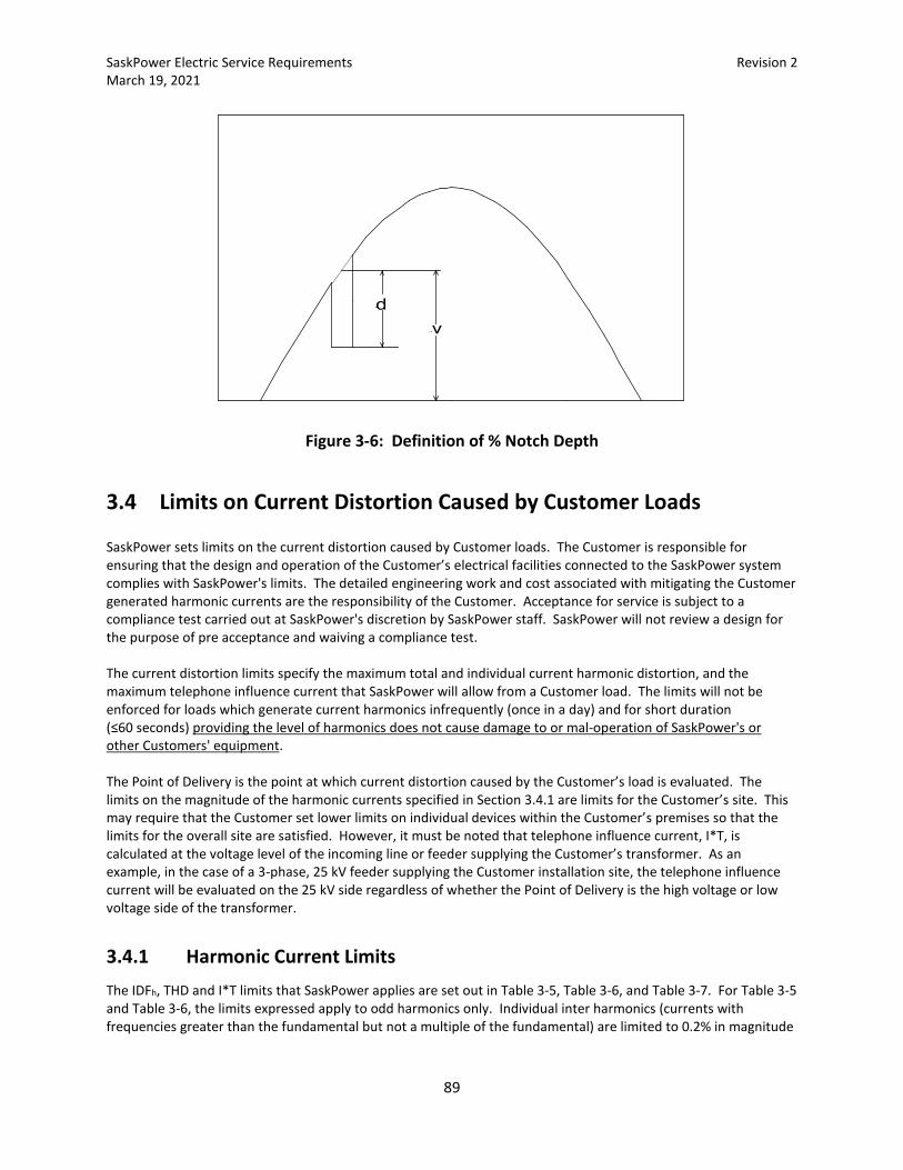
SaskPower Electric Service Requirements Revision 2 March 19, 2021
89
Figure 3-6: Definition of % Notch Depth
3.4 Limits on Current Distortion Caused by Customer Loads
SaskPower sets limits on the current distortion caused by Customer loads. The Customer is responsible for ensuring that the design and operation of the Customer’s electrical facilities connected to the SaskPower system complies with SaskPower's limits. The detailed engineering work and cost associated with mitigating the Customer generated harmonic currents are the responsibility of the Customer. Acceptance for service is subject to a compliance test carried out at SaskPower's discretion by SaskPower staff. SaskPower will not review a design for the purpose of pre acceptance and waiving a compliance test. The current distortion limits specify the maximum total and individual current harmonic distortion, and the maximum telephone influence current that SaskPower will allow from a Customer load. The limits will not be enforced for loads which generate current harmonics infrequently (once in a day) and for short duration (≤60 seconds) providing the level of harmonics does not cause damage to or mal-operation of SaskPower's or other Customers' equipment. The Point of Delivery is the point at which current distortion caused by the Customer’s load is evaluated. The limits on the magnitude of the harmonic currents specified in Section 3.4.1 are limits for the Customer’s site. This may require that the Customer set lower limits on individual devices within the Customer’s premises so that the limits for the overall site are satisfied. However, it must be noted that telephone influence current, I*T, is calculated at the voltage level of the incoming line or feeder supplying the Customer’s transformer. As an example, in the case of a 3-phase, 25 kV feeder supplying the Customer installation site, the telephone influence current will be evaluated on the 25 kV side regardless of whether the Point of Delivery is the high voltage or low voltage side of the transformer.
3.4.1 Harmonic Current Limits The IDFh, THD and I*T limits that SaskPower applies are set out in Table 3-5, Table 3-6, and Table 3-7. For Table 3-5 and Table 3-6, the limits expressed apply to odd harmonics only. Individual inter harmonics (currents with frequencies greater than the fundamental but not a multiple of the fundamental) are limited to 0.2% in magnitude
dv
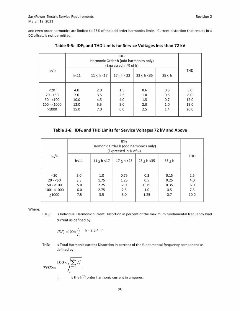
SaskPower Electric Service Requirements Revision 2 March 19, 2021
90
and even order harmonics are limited to 25% of the odd order harmonics limits. Current distortion that results in a DC offset, is not permitted.
Table 3-5: IDFh and THD Limits for Service Voltages less than 72 kV
IDFh Harmonic Order h (odd harmonics only)
(Expressed in % of IF)
ISC/IF THD h<11 11 < h <17 17 < h <23 23 < h <35 35 < h
<20 4.0 2.0 1.5 0.6 0.3 5.0 20 - <50 7.0 3.5 2.5 1.0 0.5 8.0
50 - <100 10.0 4.5 4.0 1.5 0.7 12.0 100 - <1000 12.0 5.5 5.0 2.0 1.0 15.0
>1000 15.0 7.0 6.0 2.5 1.4 20.0
Table 3-6: IDFh and THD Limits for Service Voltages 72 kV and Above
IDFh Harmonic Order h (odd harmonics only)
(Expressed in % of IF)
ISC/IF THD h<11 11 < h <17 17 < h <23 23 < h <35 35 < h
<20 2.0 1.0 0.75 0.3 0.15 2.5 20 - <50 3.5 1.75 1.25 0.5 0.25 4.0
50 - <100 5.0 2.25 2.0 0.75 0.35 6.0 100 - <1000 6.0 2.75 2.5 1.0 0.5 7.5
>1000 7.5 3.5 3.0 1.25 0.7 10.0
Where:
IDFh: is Individual Harmonic current Distortion in percent of the maximum fundamental frequency load current as defined by:
F
hh I
IIDF ×=100 h = 2,3,4...n
THD: is Total Harmonic current Distortion in percent of the fundamental frequency component as
defined by:
F
n
hh
I
ITHD
∑=
×= 2
2100
Ih is the hth order harmonic current in amperes.
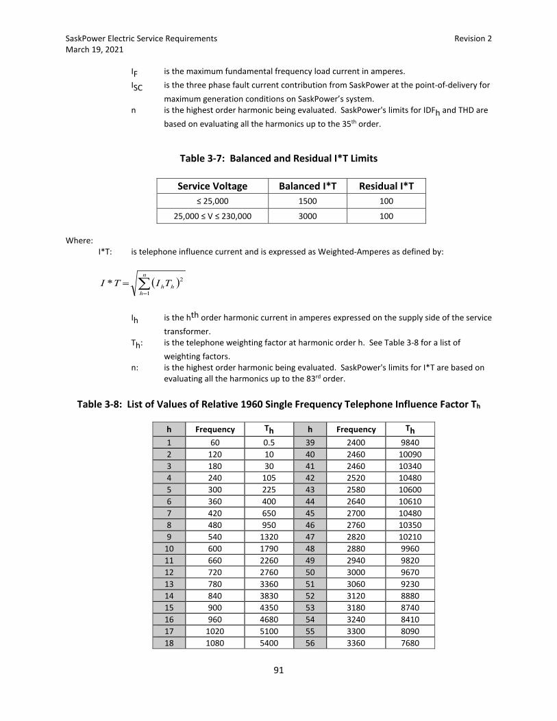
SaskPower Electric Service Requirements Revision 2 March 19, 2021
91
IF is the maximum fundamental frequency load current in amperes. ISC is the three phase fault current contribution from SaskPower at the point-of-delivery for
maximum generation conditions on SaskPower’s system. n is the highest order harmonic being evaluated. SaskPower's limits for IDFh and THD are
based on evaluating all the harmonics up to the 35th order.
Table 3-7: Balanced and Residual I*T Limits
Service Voltage Balanced I*T Residual I*T ≤ 25,000 1500 100
25,000 ≤ V ≤ 230,000 3000 100 Where:
I*T: is telephone influence current and is expressed as Weighted-Amperes as defined by:
( )∑=
=n
hhhTITI
1
2*
Ih is the hth order harmonic current in amperes expressed on the supply side of the service
transformer. Th: is the telephone weighting factor at harmonic order h. See Table 3-8 for a list of
weighting factors. n: is the highest order harmonic being evaluated. SaskPower's limits for I*T are based on
evaluating all the harmonics up to the 83rd order.
Table 3-8: List of Values of Relative 1960 Single Frequency Telephone Influence Factor Th
h Frequency Th h Frequency Th
1 60 0.5 39 2400 9840 2 120 10 40 2460 10090 3 180 30 41 2460 10340 4 240 105 42 2520 10480 5 300 225 43 2580 10600 6 360 400 44 2640 10610 7 420 650 45 2700 10480 8 480 950 46 2760 10350 9 540 1320 47 2820 10210
10 600 1790 48 2880 9960 11 660 2260 49 2940 9820 12 720 2760 50 3000 9670 13 780 3360 51 3060 9230 14 840 3830 52 3120 8880 15 900 4350 53 3180 8740 16 960 4680 54 3240 8410 17 1020 5100 55 3300 8090 18 1080 5400 56 3360 7680
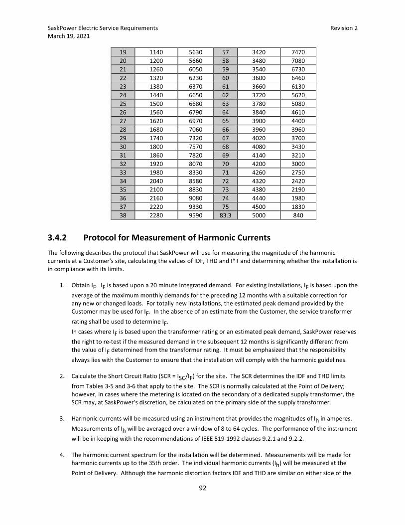
SaskPower Electric Service Requirements Revision 2 March 19, 2021
92
19 1140 5630 57 3420 7470 20 1200 5660 58 3480 7080 21 1260 6050 59 3540 6730 22 1320 6230 60 3600 6460 23 1380 6370 61 3660 6130 24 1440 6650 62 3720 5620 25 1500 6680 63 3780 5080 26 1560 6790 64 3840 4610 27 1620 6970 65 3900 4400 28 1680 7060 66 3960 3960 29 1740 7320 67 4020 3700 30 1800 7570 68 4080 3430 31 1860 7820 69 4140 3210 32 1920 8070 70 4200 3000 33 1980 8330 71 4260 2750 34 2040 8580 72 4320 2420 35 2100 8830 73 4380 2190 36 2160 9080 74 4440 1980 37 2220 9330 75 4500 1830 38 2280 9590 83.3 5000 840
3.4.2 Protocol for Measurement of Harmonic Currents The following describes the protocol that SaskPower will use for measuring the magnitude of the harmonic currents at a Customer's site, calculating the values of IDF, THD and I*T and determining whether the installation is in compliance with its limits.
1. Obtain IF. IF is based upon a 20 minute integrated demand. For existing installations, IF is based upon the average of the maximum monthly demands for the preceding 12 months with a suitable correction for any new or changed loads. For totally new installations, the estimated peak demand provided by the Customer may be used for IF. In the absence of an estimate from the Customer, the service transformer rating shall be used to determine IF.
In cases where IF is based upon the transformer rating or an estimated peak demand, SaskPower reserves the right to re-test if the measured demand in the subsequent 12 months is significantly different from the value of IF determined from the transformer rating. It must be emphasized that the responsibility always lies with the Customer to ensure that the installation will comply with the harmonic guidelines.
2. Calculate the Short Circuit Ratio (SCR = ISC/IF) for the site. The SCR determines the IDF and THD limits
from Tables 3-5 and 3-6 that apply to the site. The SCR is normally calculated at the Point of Delivery; however, in cases where the metering is located on the secondary of a dedicated supply transformer, the SCR may, at SaskPower's discretion, be calculated on the primary side of the supply transformer.
3. Harmonic currents will be measured using an instrument that provides the magnitudes of Ih in amperes.
Measurements of Ih will be averaged over a window of 8 to 64 cycles. The performance of the instrument will be in keeping with the recommendations of IEEE 519-1992 clauses 9.2.1 and 9.2.2.
4. The harmonic current spectrum for the installation will be determined. Measurements will be made for
harmonic currents up to the 35th order. The individual harmonic currents (Ih) will be measured at the Point of Delivery. Although the harmonic distortion factors IDF and THD are similar on either side of the
SaskPower Electric Service Requirements Revision 2 March 19, 2021
93
service transformer, the triplen (triplens are odd multiples of the third order harmonic) harmonic distortion factors and residual (neutral) current may be deleted from the computation of THD, I*T and the evaluation of IDF limits if the service transformer has a delta or ungrounded star connected primary winding.
• For periodic (cyclical) loads such as mine hoists, electric excavators, etc., the magnitude of the
harmonic currents may vary during the load cycle. A sufficient number of measurements will be taken over the load cycle to determine the maximum values for each harmonic order (Ih) during the load cycle. The IDF values for the load will be calculated from each of these individual maximums and will be used to determine compliance with the IDF limits. The THD values will be calculated for each individual measurement. The highest value of THD from this set of measurements will be used to determine compliance with the THD limits. The IDF and THD values will not be averaged over the period of the load cycle. The worst case will be used to assess compliance with the harmonic limits.
• For aperiodic loads, a sufficient number of measurements will be taken at various load levels to
determine the highest values for Ih. The IDF values for the load will be calculated from each of the maximum values of Ih and will be used to determine compliance with the IDF limits. The THD values will be calculated for each individual measurement. The highest value of THD from this set of measurements will be used to determine compliance with the THD limits. The worst case will be used to assess compliance with the harmonic limits.
5. I*T will be calculated for each measurement. The values of Ih used in the calculation of I*T will be those
which will flow in the utility network, even if the Point of Delivery is on the secondary side of a dedicated supply transformer. As an example, if the Ih measurements are made on the secondary of a 25 000 - 600 volt transformer, the value of Ih to be used in the calculation of I*T will be scaled by the ratio 600/25 000. The worst case will be used to assess compliance with the harmonic limits.
SaskPower Electric Service Requirements Revision 2 March 19, 2021
94
4. Requirements for Customer Owned Substations Greater Than 5 kV
4.1 Jurisdiction
4.1.1 SaskPower Electrical Inspections Division All Customer-owned substation requirements and regulations shall be designed as per the Code. Drawings, and any subsequent revisions, of electrical single line, site plan, electrical arrangements, and pertinent equipment specifications shall be submitted before construction to the SaskPower Electrical Inspections Division, for review. All Customer owned high voltage substations shall be inspected by the SaskPower Electrical Inspections Division prior to being energized.
4.1.2 SaskPower Transmission and Distribution SaskPower Transmission and Distribution involvement within the Customer substation will be limited to the following areas:
• Connections at point of delivery. • Electrical Clearances (Point of delivery to load side of protection equipment). • Protection Co-ordination. • Insulation Co-ordination.
Where the design of the proposed substation related to the connections, clearances, protection co-ordination and insulation co-ordination is of concern, SaskPower Transmission and Distribution will indicate the recommended modifications.
4.1.3 SaskPower Customer Services SaskPower Customer Services, Metering Services involvement within the Customer substation will be limited to revenue metering. Where the design of the proposed substation related to revenue metering is of concern, SaskPower Customer Services, Metering Services will indicate the recommended modifications.
SaskPower Electric Service Requirements Revision 2 March 19, 2021
95
4.2 General Requirements
4.2.1 Voltages All voltages quoted herein are nominal phase to phase voltages, unless otherwise specified.
4.2.2 SaskPower Required Drawings In addition to the requirements of the SaskPower Electrical Inspections Division, the Customer shall submit three copies of their installation drawings to the appropriate SaskPower Business Manager. These drawings will be distributed by the SaskPower Business Manager to the Transmission, Distribution and Customer Services, and Metering Services departments as required. Installation drawing dimensions are to be shown in metric, and contain the following:
• Substation plot plan showing the location of the substation in relation to the provincial survey system. • Layout plan indicating the location of all existing and proposed roads, civil structures, site improvements,
communication towers, and electrical equipment. • Single line and three line diagrams of complete electrical system including Customer’s apparatus
designations and phasing orientation. • Substation layout plan indicating the ground grid and fence grounding systems. • Substation structure drawings indicating:
Center Phase of Termination structure Geo-referenced to UTM NAD83 Zone 13 Extended Structure details for conductor and shield wire termination and isolating switch. Location of revenue metering units and conduit to these units. If revenue metering is to be installed
in switchgear, a drawing indicating the proposed revenue metering installation, including the instrument transformer compartment, is required.
Transformer, circuit breaker, surge arresters, etc.
After reviewing the supplied drawings, SaskPower will advise the Customer of any necessary corrections required to comply with SaskPower's requirements. The Customer shall submit revised drawings to SaskPower Customer Services, to confirm corrections requested by SaskPower. Substation design must be submitted to SaskPower Electrical Inspections for approval.
4.3 Service Requirements
4.3.1 Extending Supply Service from 15 kV or 25 kV System
4.3.1.1 Aerial Supply
SaskPower will extend an aerial supply service to the Customer owned deadend insulators located within the Customer's substation. The deadend insulators will be the point of delivery. The ownership of facilities to the point of delivery will remain with SaskPower.
SaskPower Electric Service Requirements Revision 2 March 19, 2021
96
4.3.1.2 Buried Supply
SaskPower will extend a buried supply service to the Customer's equipment. The ownership of facilities to the point of delivery will remain with SaskPower. Options are:
• Customer supplied switchgear. The point of delivery shall be the cable termination in the switchgear. • Customer supplied padmounted switch, as per Code.
For a dead-front switch, the point of delivery shall be the high voltage load-break bushings. The bushings shall consist of a short load-break bushing insert with integral partial vacuum flashover solution, Elastimold Cat. No. 2701A4A, Cooper Cat. LBI225, or a SaskPower approved equivalent. SaskPower will terminate the supply conductors with separable insulated connectors (elbows).
For a live-front switch, the point of delivery shall be the high voltage cable terminations. • The Customer shall ensure that the switchgear cable termination compartment and the padmounted
switch have adequate phase barriers and grounding means. Where working space (3m) or electrical clearance is insufficient to safely install grounds, a ground switch is required.
4.3.2 Extending Supply Service from 72 kV, 138 kV, or 230 kV Aerial System SaskPower will extend an aerial supply service to the Customer owned termination structure located within the Customer’s substation. The SaskPower supplied riser conductor will be the point of delivery as per Figure 4-5. The ownership of facilities to the point of delivery will remain with SaskPower.
4.3.3 Metering
4.3.3.1 General
Three element metering shall be used for all new installations. The Customer shall provide adequate space for installation of three voltage transformers and three current transformers. Due to the numerous options for metering the Customer, such as pole-mount, padmount, switchgear, etc., the Customer shall contact the appropriate SaskPower Business Manager to determine details for the specific application.
4.3.3.1.1 15 kV or 25 kV Aerial Supply Metering Options
• Customer owned overhead facilities, similar to Figure 4-1. SaskPower will utilize pole mounted instrument transformers, which shall be installed immediately on the load side of the Customer's supply isolating switches. The Customer is responsible for connection of the Customer supplied conductors to the SaskPower supplied bypass switch.
• Customer supplied padmounted metering cabinet (1), as per Code, with Customer supplied primary cable to the metering cabinet. The metering cabinet shall include a separate compartment for SaskPower's instrument transformers.
• Customer supplied switchgear, similar to Figure 4-2 (1). The Customer shall provide a separate compartment for SaskPower's instrument transformers. This compartment shall be located immediately on the load side of the Customer's point of isolation in the switchgear.
Note (1): The Customer shall ensure that the switchgear or padmounted metering cabinet have
adequate phase barriers and grounding means. Where working space (3m) or electrical clearance is insufficient to safely install grounds, a ground switch is required.
SaskPower Electric Service Requirements Revision 2 March 19, 2021
97
4.3.3.1.2 15 kV or 25 kV Buried Supply Metering Options
• Customer supplied padmounted metering cabinet (2), as per Code. The padmounted metering cabinet shall include a separate compartment for SaskPower's instrument transformers.
• Customer supplied switchgear, similar to Figure 4-2 (2). The Customer shall provide a separate compartment for SaskPower's instrument transformers. This compartment shall be located immediately on the load side of the Customer's point of isolation in the switchgear.
Note (2): The Customer shall ensure that the switchgear or padmounted metering cabinet have
adequate phase barriers and grounding means. Where working space (3m) or electrical clearance is insufficient to safely install grounds, a ground switch is required.
4.3.3.1.3 72 kV, 138 kV, or 230 kV Aerial Supply Metering Options
• Customer owned overhead facilities. Instrument transformers required for SaskPower’s revenue metering shall be installed immediately on the load side of the Customer’s gang operated supply switch. For individual instrument transformers, voltage transformers shall be installed on the line side of the current transformers. The Customer is responsible for connection of the Customer supplied conductor to the SaskPower supplied connectors on the instrument transformers.
• As a customer preferred alternative to instrument transformers installed on the line side of the service, SaskPower will allow metering on the secondary side of the Customer’s power transformer provided there are no technical or operational impediments. The Customer shall contact the appropriate SaskPower Account Manager to determine details for the specific application. The Customer will provide the required technical data to allow the metering instrumentation to be compensated.
4.3.3.2 Meter Mounting
4.3.3.2.1 General
• 15 kV or 25 kV Service
• SaskPower will supply and install:
• a meter and associated equipment.
• The Customer shall supply and install:
• For services with a connected load of less than 5 MVA either: • a 36” x 36” x 18” weatherproof meter cabinet, complete with backing
plate, proper grounding and window (if the Customer wishes to read the meter), or
• a minimum space of 1.2 x 1.2 x 1.2 m, located in a customer owned facility. This space shall be backed with a piece of 19 mm thick plywood, with its center line not more than 1.7 m or less than 1.2 m above floor level. The Customer shall supply and install onto the 1.2 m x 1.2 m plywood a 30” x 30” x 12” meter cabinet complete with backing plate and proper grounding.
• For services with a connected load of equal to or greater than 5 MVA: • a minimum space of 1.2 x 1.2 x 1.2 m., located in an environmentally
controlled building. This space shall be backed with a piece of 19 mm thick
SaskPower Electric Service Requirements Revision 2 March 19, 2021
98
plywood, with its center line not more than 1.7 m. or less than 1.2 m. above floor level. The Customer shall supply and install onto the 1.2 m. x 1.2 m. plywood a 30” x 30” x 12” meter cabinet complete with backing plate and proper grounding. The Customer shall supply and install a 120 VAC power supply in the meter cabinet.
• a 13-jaw combination meter socket (meter socket with sufficient space for a 10-pole test switch). This meter socket shall be mounted with the center line of the socket 1.5 m to 1.8 m above finished grade or floor level:
• inside the 36” x 36” x 18” meter cabinet, or • onto the 1.2 m x 1.2 m plywood, adjacent to the 30” x 30” x 12” meter
cabinet. The top of the meter socket must not extend beyond the plywood.
• a ground connection in the meter socket.
• 72 kV, 138 kV or 230 kV Service
• SaskPower will supply and install:
• a meter and associated equipment.
• The Customer shall:
• provide a minimum space of 1.2 x 1.2 x 1.2 m, located in an environmentally controlled building. This space shall be backed with a piece of 19 mm thick plywood, with its center line not more than 1.7 m or less than 1.2 m above floor level.
• supply and install onto the 1.2 m x 1.2 m plywood a30” x 30” x 12” meter cabinet complete with backing plate and proper grounding.
• supply and install a 13-jaw combination meter socket (meter socket with sufficient space for a 10-pole test switch). This meter socket shall be mounted onto the 1.2 m x 1.2 m plywood, adjacent to the 30” x 30” x 12” meter cabinet, and with the center line of the socket 1.5 m to 1.8 m above the floor. The top of the meter socket must not extend beyond the plywood.
• supply and install 120 VAC power supply in the meter cabinet. • supply and install a ground connection in the meter socket.
4.3.3.2.2 Switchgear
When the Customer installs switchgear, and the meter is located in the same switchgear assembly as the instrument transformers, the meter shall be located in a separate compartment. The meter compartment shall conform to the following dimensions:
• Depth - 380 mm (15") minimum to 450 mm (18")maximum • Height - 850 mm (34") minimum • Width - 600 mm (24") minimum
The meter compartment shall be equipped with a hinged door, flush with the front of the switchgear, with provisions for sealing by SaskPower. A window shall be provided if the Customer wishes to read the meter. The meter compartment shall be located so that the meter can be mounted with its center line at a height of 1.5 m to 1.8 m above floor level.
SaskPower Electric Service Requirements Revision 2 March 19, 2021
99
When the meter socket is separate from the switchgear, it may be wall-mounted adjacent to the switchgear, with approval from SaskPower Customer Services, Metering Services.
4.3.3.3 Instrument Transformers, Enclosures, and Supports
4.3.3.3.1 General
Revenue metering instrument transformers and other associated equipment supplied by SaskPower shall be used exclusively for the purpose of SaskPower revenue metering.
4.3.3.3.2 Instrument Transformers
SaskPower will:
• supply and maintain all revenue metering instrument transformers. • for aerial supply voltages of 25 kV or less, supply and install bypass switches and a cluster bracket,
complete with instrument transformers, on a Customer owned pole. SaskPower shall supply and install a ground grid at the base of the pole.
The Customer shall:
• Install the SaskPower supplied instrument transformers in the switchgear or padmounted metering cabinet, where the supply voltage is 25 kV or less.
• Contact SaskPower Customer Services, Metering Services for instrument transformer details. • Install all 72 kV, 138 kV and 230 kV instrument transformers on platform or pedestals provided by the
Customer. Instrument transformers will not be shipped out of the province for installing in switchgear or in padmounted metering cabinets. Voltage transformers, 15 kV or 25 kV class, may be equipped with one fuse per transformer centrally mounted for 3-phase, 4-wire wye circuits.
4.3.3.3.3 Instrument Transformer Enclosures
15 kV and 25 kV Buried Supply
When switchgear or padmounted metering cabinet is utilized, the Customer shall:
• provide a separate and completely barriered compartment for mounting the voltage transformers and current transformers. The compartment shall be located immediately after the isolation switch.
• ensure that the instrument transformer compartment is of sufficient size to enable maintenance and replacement of instrument transformers.
• provide a means for padlocking and sealing (by SaskPower) the instrument transformer compartment.
• install the instrument transformer enclosure a minimum of 300 mm (12") above the floor or final grade.
• in addition to the electrical clearances specified in the applicable CSA standard, provide for a minimum physical separation of 50 mm to be maintained between instrument transformers and between the instrument transformer and the surrounding switchgear to provide adequate working clearances.
SaskPower Electric Service Requirements Revision 2 March 19, 2021
100
• contact SaskPower Customer Services, Metering Services for instrument transformer installation details.
The instrument transformer compartment shall be required to be equipped with a draw out type or swing out type carriage with disconnect provisions for de-energizing and grounding the primary of each transformer upon withdrawal.
4.3.3.3.4 Instrument Transformer Supports
The Customer shall provide and install a class 4/35’ (minimum) pole for mounting the SaskPower supplied and installed bypass switches and cluster bracket/instrument transformer assembly as per Figure 4-1 for 15 kV and 25 kV aerial supplies. The Customer shall provide and install a platform or pedestals for mounting SaskPower instrument transformers, and ensure proper grounding of the platform or pedestals, for 72 kV aerial supplies. The Customer shall provide and install pedestals for mounting of SaskPower instrument transformers, and ensure proper grounding of the pedestals, for 138 kV or 230 kV aerial supplies.
4.3.3.4 Conduit and Secondary Wiring Requirements
4.3.3.4.1 15 kV or 25 kV Supply Voltages
When the instrument transformers are located indoors:
• The Customer shall supply and install:
• a continuous run of conduit (minimum 35 mm (1¼”) diameter) for the exclusive use of SaskPower between the instrument transformer enclosure and the meter enclosure, to a maximum length of 11 m.
• sealable LB fittings or similar conduit fittings, if required. • the bond on the meter socket when PVC conduit is used.
• SaskPower shall supply and install:
• a continuous run of secondary conductors in the Customer supplied conduit between the
instrument transformers and the meter test switch (such that there are no splices or interruptions).
• a test switch. When the instrument transformers are located outdoors:
• The Customer shall:
• supply and install buried 78 mm (3") PVC water tight conduit from the pole mounted instrument transformer structure, or from the padmounted metering cabinet, to the meter. When a pole mounted instrument transformer structure is used, the conduit shall extend 1200 mm up the instrument transformer structure, and be complete with a 78 mm (3") PVC expansion joint.
• obtain approval from SaskPower Customer Services, Metering Services, if the length of the 78 mm (3") PVC conduit requirement exceeds 70 meters.
• limit the number of 90 degree PVC conduit bends to four (4).
SaskPower Electric Service Requirements Revision 2 March 19, 2021
101
• SaskPower shall supply and install:
• a continuous run of secondary conductors in the Customer supplied conduit between the
instrument transformers and the meter test switch (such that there are no splices or interruptions).
• a test switch.
4.3.3.4.2 72 kV, 138 kV, or 230 kV Supply Voltages
The Customer shall:
• supply and install buried 103 mm (4") PVC water tight conduit from the instrument transformer structure to the indoor metering cabinet space provided. The conduit shall extend 1200 mm up the instrument transformer structure and be terminated on a Customer supplied junction box located on the instrument transformer structure.
• obtain approval from SaskPower Customer Services, Metering Services, if the length of the 103 mm (4") PVC conduit requirement exceeds 70 meters.
• limit the number of 90 degree PVC conduit bends to four (4). • for 72 kV supply voltage, supply and install conduit, pull boxes, and junction box as per Figure 4-3. • for 138 kV or 230 kV supply voltage, supply and install conduit, pull boxes, and junction box as per Figure
4-4. • supply and install a pull box located inside the building, and adjacent to the revenue meter.
SaskPower shall supply and install:
• a continuous run of secondary conductors in the Customer supplied conduit between the instrument transformers and the meter test switch (such that there are no splices or interruptions).
• a test switch. • flexible conduit between the instrument transformers and the Customer supplied pull box.
4.3.3.5 Metering Signals
4.3.3.5.1 General
Any Customer requiring output signals from the SaskPower revenue meter shall contact the appropriate SaskPower Business Manager for applicability, availability, details, and costs. In the event that output signals are provided to the Customer, SaskPower will not accept any liabilities with respect to the use or loss of the output signals.
4.3.3.6 Communications
4.3.3.6.1 15 kV or 25 kV Supply Voltages
The Customer is responsible for the supply and installation of SaskPower pre-approved communication devices to the revenue meter, for the exclusive use of SaskPower. Due to numerous options available, SaskPower, Metering Services may be contacted to discuss such options.

SaskPower Electric Service Requirements Revision 2 March 19, 2021
102
The communication service will be in SaskPower’s name, and payment of all monthly charges will be the responsibility of SaskPower.
4.3.3.6.2 72 kV, 138 kV, or 230 kV Supply Voltages
The Customer is responsible for the supply and installation of a dedicated PSTN communication line to the revenue meter, for the exclusive use of SaskPower. The communication service will be in SaskPower’s name, and payment of all monthly charges will be the responsibility of SaskPower.
4.4 Specifications
4.4.1 Aerial Supply Conductors
4.4.1.1 Phase Spacing
A slack span is required from SaskPower line terminal to the Customer-supplied termination structure as per Fig 4-5. Phase spacing shall be sufficient in order to prevent phase-to-phase faults under severe wind conditions. Minimum slack span phase spacing on SaskPower substations is: 1.2 m for 15 kV 1.2 m for 25 kV 3.5 m for 72 kV 4.0 m for 138 kV 6.0 m for 230 kV These separations are required for the mounting tabs for the SaskPower-supplied deadend insulators located on the Customer's termination structure.
4.4.1.2 Lightning Protection (Shield) Wires
At voltages above 25 kV, lightning protection may be provided on the transmission lines by one or two shield wires, depending on the type of construction. The shield wire(s) will be insulated from the Customer’s termination structure and ground grid.
4.4.1.3 Deadend Tensions
Customer-owned termination structure(s) as per Fig 4-5 shall be designed to withstand the following mechanical loads:
• Maximum tension per phase conductor - 6672 N (1500 lb.) • Maximum tension per shield wire - 4450 N (1000 lb.)
The above tensions are required to permit sufficient ground clearance for phase conductors and sufficient shield wire to phase conductor clearance for the slack spans. Safety factors are not included in these values. This information shall be indicated on drawings of the proposed Customer substation.
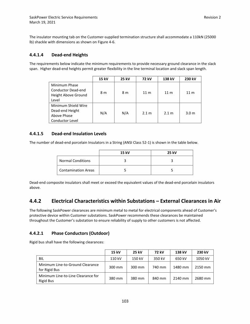
SaskPower Electric Service Requirements Revision 2 March 19, 2021
103
The insulator mounting tab on the Customer-supplied termination structure shall accommodate a 110kN (25000 lb) shackle with dimensions as shown on Figure 4-6.
4.4.1.4 Dead-end Heights
The requirements below indicate the minimum requirements to provide necessary ground clearance in the slack span. Higher dead-end heights permit greater flexibility in the line terminal location and slack span length.
15 kV 25 kV 72 kV 138 kV 230 kV Minimum Phase Conductor Dead-end Height Above Ground Level
8 m 8 m 11 m 11 m 11 m
Minimum Shield Wire Dead-end Height Above Phase Conductor Level
N/A N/A 2.1 m 2.1 m 3.0 m
4.4.1.5 Dead-end Insulation Levels
The number of dead-end porcelain Insulators in a String (ANSI Class 52-1) is shown in the table below.
15 kV 25 kV
Normal Conditions 3 3
Contamination Areas 5 5
Dead-end composite insulators shall meet or exceed the equivalent values of the dead-end porcelain insulators above.
4.4.2 Electrical Characteristics within Substations – External Clearances in Air The following SaskPower clearances are minimum metal to metal for electrical components ahead of Customer’s protective device within Customer substations. SaskPower recommends these clearances be maintained throughout the Customer’s substation to ensure reliability of supply to other customers is not affected.
4.4.2.1 Phase Conductors (Outdoor)
Rigid bus shall have the following clearances:
15 kV 25 kV 72 kV 138 kV 230 kV BIL 110 kV 150 kV 350 kV 650 kV 1050 kV Minimum Line-to-Ground Clearance for Rigid Bus 300 mm 300 mm 740 mm 1480 mm 2150 mm
Minimum Line-to-Line Clearance for Rigid Bus 380 mm 380 mm 840 mm 2140 mm 2680 mm
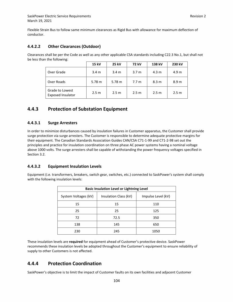
SaskPower Electric Service Requirements Revision 2 March 19, 2021
104
Flexible Strain Bus to follow same minimum clearances as Rigid Bus with allowance for maximum deflection of conductor.
4.4.2.2 Other Clearances (Outdoor)
Clearances shall be per the Code as well as any other applicable CSA standards including C22.3 No.1, but shall not be less than the following:
15 kV 25 kV 72 kV 138 kV 230 kV
Over Grade 3.4 m 3.4 m 3.7 m 4.3 m 4.9 m
Over Roads 5.78 m 5.78 m 7.7 m 8.3 m 8.9 m
Grade to Lowest Exposed Insulator 2.5 m 2.5 m 2.5 m 2.5 m 2.5 m
4.4.3 Protection of Substation Equipment
4.4.3.1 Surge Arresters
In order to minimize disturbances caused by insulation failures in Customer apparatus, the Customer shall provide surge protection via surge arresters. The Customer is responsible to determine adequate protective margins for their equipment. The Canadian Standards Association Guides CAN/CSA C71-1-99 and C71-2-98 set out the principles and practice for insulation coordination on three phase AC power systems having a nominal voltage above 1000 volts. The surge arresters shall be capable of withstanding the power frequency voltages specified in Section 3.2.
4.4.3.2 Equipment Insulation Levels
Equipment (i.e. transformers, breakers, switch gear, switches, etc.) connected to SaskPower's system shall comply with the following insulation levels:
Basic Insulation Level or Lightning Level
System Voltages (kV) Insulation Class (kV) Impulse Level (kV)
15 15 110
25 25 125
72 72.5 350
138 145 650
230 245 1050 These insulation levels are required for equipment ahead of Customer’s protective device. SaskPower recommends these insulation levels be adopted throughout the Customer’s equipment to ensure reliability of supply to other Customers is not affected.
4.4.4 Protection Coordination SaskPower’s objective is to limit the impact of Customer faults on its own facilities and adjacent Customer
SaskPower Electric Service Requirements Revision 2 March 19, 2021
105
facilities. If the Customer’s facilities are supplied via SaskPower facilities with a primary voltage of 72 kV or higher, high speed clearing of the fault (removal of the fault within 100 milliseconds of inception of the fault) may be a requirement. The requirement will normally be based upon the drop in the positive sequence voltage that occurs during the fault. If the positive sequence voltage at the point of common coupling drops to less than 85% of nominal during the fault, high speed clearing may be required. The need for high speed clearing must be assessed in conjunction with SaskPower. It should be noted that the coordination of protection is for the protection of SaskPower equipment and the maintenance of services to other Customers. SaskPower cannot assume responsibility for the protection of Customer-owned equipment. The Customer is advised that under- and over-voltage and under- and over-frequency conditions can occur. SaskPower powerlines may be equipped with high-speed automatic reclose equipment which can be either single-phase or three-phase in operation. Refer to Section 3.2 for a further discussion of the characteristics of the SaskPower system. The Customer shall take suitable precautions for the protection of his equipment. Refer to Section 3 for further details. At voltages above 72kV, SaskPower Transmission & Distribution requires the use of a circuit breaker or circuit switcher as the automatic circuit interrupting device on the high voltage side of a Customer owned substation. Breakers and circuit switchers provide superior protection when compared to fuses. They are superior in that they eliminate single-phasing, increase flexibility for coordination, and eliminate the nuisance of "sneak-outs" (i.e. fuse blowing due to long-term deterioration of the fuse element). At voltages of 72 kV or higher, SaskPower Transmission & Distribution requires that the Customer’s transformer use a delta connected or ungrounded wye connected high voltage winding. If the Customer has, or anticipates that they may have on-site generation which operates synchronously with SaskPower’s system, they should refer to the requirements set out in the following SaskPower documents:
Generation Interconnection Requirements at Voltages 34.5 kV and Below, or Non-Utility Generation Interconnection Requirements at Voltages 72 kV and Above
The Customer shall confirm settings of protection relays or size of fusing with SaskPower Transmission & Distribution to insure coordination with SaskPower owned equipment and that service to other customers will be safe and reliable.
4.4.5 Customer Equipment Coordination The characteristics of the Customer’s facilities and load can affect SaskPower’s system. Customers are required to insure that their facilities comply with the power quality requirements set out in Section 3. In order to insure coordination of their facilities, the Customer will be required to provide SaskPower with the characteristics of their facility. These data requirements will be identified by SaskPower Customer Services at the time the Customer applies for service. The type of data required will depend on the service voltage and the nature of the Customer’s load.
4.4.6 Disconnection of Substation from Transmission Line Maintenance, safety, and SaskPower system operation considerations require a disconnect switch (either motorized or manual) to disconnect the Customer substation from the transmission line. The disconnect device shall be located on the line side of metering transformers and any customer equipment including surge arrestors. It is recommended that the Customer consider a 3-phase manually operated ground switch to be used on the load side of the disconnect device.

SaskPower Electric Service Requirements Revision 2 March 19, 2021
106
4.4.7 Phase Rotation Phases on SaskPower's system are designated by the colors Red, Yellow, and Blue, with the phase rotation being POSITIVE R-Y-B (A-B-C) counter-clockwise direction. In general, the connection of the primary supply line to the Customer's substation shall be such that Red phase is to the H1 transformer bushing, Yellow phase is to the H2 bushing, and Blue phase is to the H3 bushing or maintain positive sequence of YBR or BRY. In cases where it may be necessary or desirable to have the phases connected in a manner different from the above standard, the phasing will be established by mutual agreement between the Customer and SaskPower.
4.4.8 Ambient Conditions All customer equipment must be capable of withstanding the required voltages, conducting the required current, and interrupting the required fault current in the required time within an ambient temperature range of -50 degrees C to + 45 degrees C.

SaskPower Electric Service Requirements Revision 2 March 19, 2021
107
4.5 Figures