electric service handbook - kootenai electric co-op | kec and pdfs/electric... · kootenai electric...
TRANSCRIPT
Electric Service Handbook
Kootenai Electric Cooperative2451 W. Dakota AvenueHayden, Idaho 83835www.kec.com208.765.1200
KEC Electric Service Handbook, Edition #20, July 1, 2017
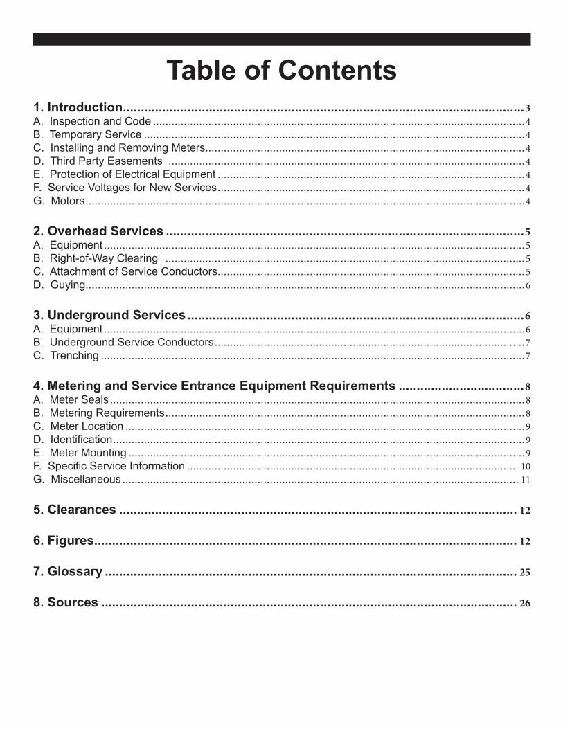
Table of Contents1. Introduction ................................................................................................................3A. Inspection and Code .........................................................................................................................4B. Temporary Service ............................................................................................................................4C. Installing and Removing Meters........................................................................................................4D. Third Party Easements ....................................................................................................................4E. Protection of Electrical Equipment ....................................................................................................4F. Service Voltages for New Services ....................................................................................................4G. Motors ...............................................................................................................................................4
2. Overhead Services ....................................................................................................5A. Equipment .........................................................................................................................................5B. Right-of-Way Clearing .....................................................................................................................5C. Attachment of Service Conductors....................................................................................................5D. Guying...............................................................................................................................................6
3. Underground Services ..............................................................................................6A. Equipment .........................................................................................................................................6B. Underground Service Conductors .....................................................................................................7C. Trenching ..........................................................................................................................................7
4. Metering and Service Entrance Equipment Requirements ...................................8A. Meter Seals .......................................................................................................................................8B. Metering Requirements .....................................................................................................................8C. Meter Location ..................................................................................................................................9D. Identification ......................................................................................................................................9E. Meter Mounting .................................................................................................................................9F. Specific Service Information ............................................................................................................ 10G. Miscellaneous ................................................................................................................................. 11
5. Clearances ............................................................................................................... 12
6. Figures...................................................................................................................... 12
7. Glossary ................................................................................................................... 25
8. Sources .................................................................................................................... 26

Kootenai Electric Cooperative
3KEC Electric Service Handbook, Edition #20, July 2017
1. IntroductionThe information in this booklet is intended to provide electrical contractors, architects, building contractors, engineers and Cooperative members with Kootenai Electric Cooperative requirements for all line extensions. The booklet provides most of the information and requirements. It does not include all the possible standards or specifications required by KEC, state, federal or local code requirements.
Engineering, scheduling and construction of the work will vary depending upon the complexity of the job, as well as KEC’s workload. Contact KEC at 208.765.1200 for current scheduling information.
When requesting your service installation and to ensure prompt service, it is important to provide the Member Services Representative with all the information requested in the Line Extension Application and the associated application packet. When easements are required, they must be obtained prior to construction.
As a reminder, please refer to our website at www.kec.com for the most recent line extension application forms. We continue to make changes and out of date forms will not be accepted.
Please use the checklist below to assist you in the new service process.
Applicant works with a Member Services Representative (MSR)• Complete application packet.• Sign all required forms.• Provide all necessary documents outlined in packet.• Provide, sign and notarize easement (provide any third party easements if applicable).
MSR submits application to Field Technician• Field technician meets applicant on-site (not applicable in a high density subdivision).
Field Technician provides cost quote• Operations Coordinator will contact applicant regarding the cost quote.• Applicant must pay cost prior to commencing construction.
Meter base installation• Email electrical permit to [email protected].• Complete State inspection if homeowner installed.• Contact KEC at 208.292.3228 once inspections have been completed.• Clear right-of-way if applicable.• If state licensed electrician pulls permit and performs meter base installation—state electrical inspection will not be necessary prior to energizing. • KEC requires that pictures of meter base showing slip joint and ground rod(s) and/or UFER and disconnect be emailed to [email protected].
Inspection and scheduling• Once approved, job is released to the operations department to schedule construction of KEC facilities.
Kootenai Electric Cooperative
3
p
p
p
p
p
Kootenai Electric Cooperative
4KEC Electric Service Handbook, Edition #20, July 2017
A. Inspection and CodeThe member is responsible for complying with all requirements for temporary and permanent service equipment.
All of your electrical equipment must comply with the most current edition of the National Electric Code (NEC) and any state or local code requirements. Idaho electrical inspectors can answer any NEC code questions. Call 1.800.955.3044 for an Idaho electrical inspection. State electrical inspectors are available to answer code-related questions from 8 a.m. to 5 p.m. Monday through Friday.A state electrical permit must be obtained to initiate electrical service. On homeowner-installed service equipment, the service equipment and the installation must be approved by the state electrical bureau prior to energizing the service.
For further information regarding inspections, permits, codes and easements, contact KEC at 208.765.1200.
B. Temporary ServiceFor homeowner installed temporary services, KEC will connect and install an electric meter only after inspection and approval by the state electrical inspector.
C. Installing and Removing MetersOnly authorized and qualified KEC personnel may install and remove meters. With some types of meter sockets, removal of the meter does not de-energize the existing system.
D. Third Party Easements Any third party easements are the responsibility of the applicant to obtain and submit to KEC. KEC will assist in the process of providing a blank easement for signature; however it is the applicant’s responsibility to work with land owners. All easements will be recorded by KEC and must comply with KEC Policy No. 3-4.
E. Protection of Electrical EquipmentThe member shall provide protective equipment as required by the National Electric Code (NEC) or other applicable code(s). For all three-phase motor installations, the member is responsible for installing protection equipment against loss of phase conditions.
F. Service Voltages for New ServicesFor single-phase installations, 120/240 volt service is available. This is the typical three-wire service used for residences. 120 volt, two-wire service is not available.
For three-phase installations, 120/208 and 277/480 volt services are available. These are the typical four-wire services used in commercial buildings and irrigation. KEC no longer accepts any new delta services. 120/240 three-phase and 240/480 three-phase services are not available.
G. Motors• The maximum motor size allowed on a single-phase line is 10 hp.• All motors 20 hp or larger shall have soft starting.• The maximum motor size allowed on a two-phase line is 15 hp.• Variable frequency drives must meet the industry standard (IEEE Standard 519-1992) for harmonics. If they
don’t, it is the member’s responsibility to provide the necessary harmonic filters to bring the installation into compliance.

Kootenai Electric Cooperative
5KEC Electric Service Handbook, Edition #20, July 2017
2. Overhead ServicesThis chapter covers requirements for overhead service installations at secondary voltages less than 600 volts.
A. EquipmentThe member must furnish, install and maintain all required service entrance equipment, including wire, service mast, weatherhead and any guying required. (Refer to Section 4).
KEC will furnish, install and maintain the service conductors, connectors, service dead-end clamp and meter.
Conduit size depends on the size and number of conductors in the conduit. Contact your electrician for proper conduit size. This is governed by the National Electric Code (NEC).
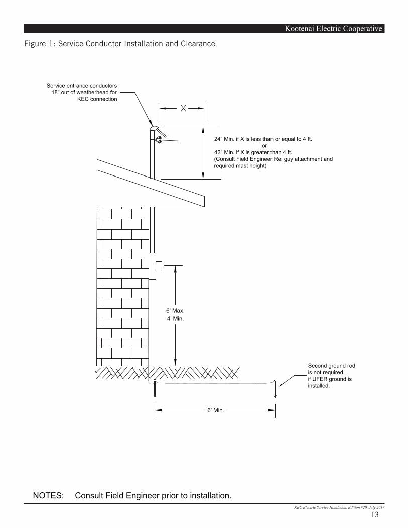
The mast provided for attachment of the service conductors must be a minimum of two inch (in.) rigid steel galvanized conduit and provide a structurally sound attachment for the service conductors and must extend up above the roof (see Figure 1).
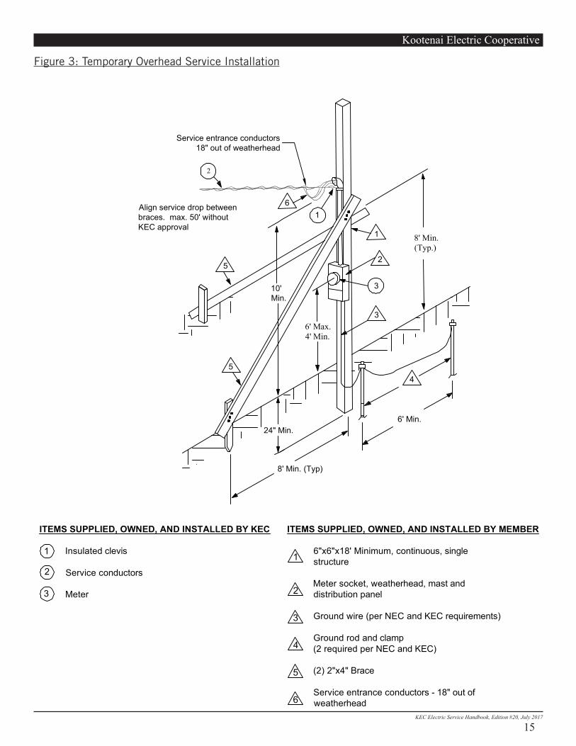
• The overhead temporary service pole must be a continuous, single structure, 6 in. x 6 in. x 18 feet (ft.) minimum, and should be located in close proximity to the transformer pole. Any temporary service over 50 ft. (see Figure 3) must be approved by KEC. Location of the temporary service may require additional post height.
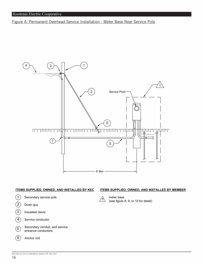
• Normally, the meter base will be installed on the structure. • KEC no longer allows meter bases to be installed on KEC poles. If the meter base cannot be installed on the
structure, see Figure 4 for service installation. Service pole metering will also work in conjunction with Figures 8-10.
• For additional information, contact KEC at 208.765.1200.
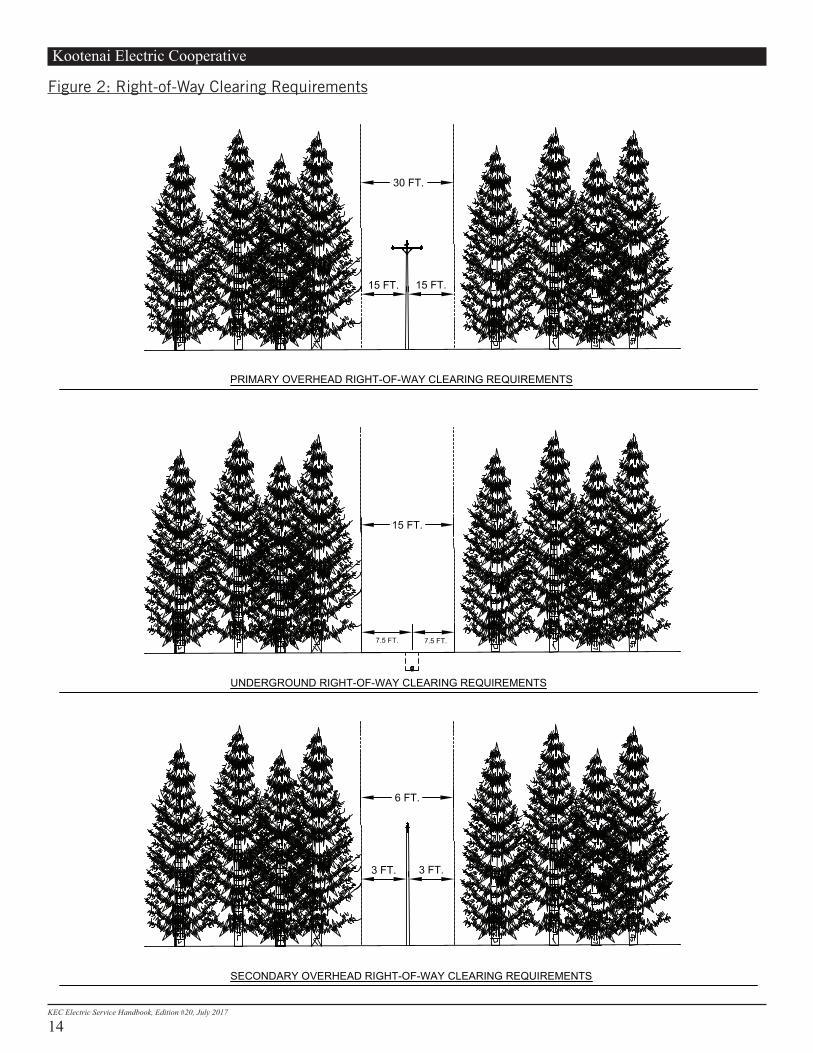
B. Right-of-Way Clearing A clearance of 30 ft. is required for all primary overhead Right-of-Way clearing (see Figure 2). The member is responsible for the initial right-of-way clearing. If this clearing is within a state or county road right-of-way, then a permit is required and the necessary liability insurance must be obtained. C. Attachment of Service Conductors• Service entrance conductors must extend at least 18 in. out of the weatherhead to permit connection to the
service conductors. • The service mast should be located to facilitate only one attachment of the service conductors to the
building.• Do not terminate service conductors on chimneys, vent pipes, gutters or other non structural portions of the
building. Suitable service attachment devices should be provided and installed during construction.
Service Conductor Clearance• Before the service is installed, the member must provide a path clear of buildings, trees or other obstructions
between KEC’s pole and the point of attachment (see Figure 2). Clearances from any obstruction - vertical or horizontal - must be in accordance with this section.
• On permanent overhead services KEC will need to attach service conductors a minimum of 12 ft. and a maximum of 25 ft. above final grade and must comply with the minimum NESC requirements. The bottom of the drip loop must be a minimum of 10 ft. above final grade.

Kootenai Electric Cooperative
6KEC Electric Service Handbook, Edition #20, July 2017
• Only power service drop conductors are allowed to be attached to the electrical mast.
Clearance above Roofs (See Figure 1)Service conductors must have a vertical clearance of at least 3 ft. from all roofs above which they pass over that are not readily accessible. They must have a vertical clearance of 18 in. for a horizontal distance of 6 ft. from an approved raceway or support located not more than 4 ft. from the edge of the roof and not less than 3 ft. for the remainder of the horizontal distance that the cable or conductor passes over the roof.
Clearance from Building OpeningsAllow a minimum of 3 ft. of clearance between service conductors and windows, doors, porches, fire escapes or similar locations. Service conductors above a window are considered clear of that window.
D. GuyingA guy is not required on service masts 26 in. or less above the roof when the service conductor is #2 triplex or smaller, and less than 100 ft. long. All other service masts require guying (see Figure 1). The service conductor attachment must be a minimum of 18 in. above the roof.
Overhead temporary meter poles must have two 2 in. x 4 in. braces securely fastened to the post with the service aligned between them (see Figure 3).
3. Underground ServicesThis chapter covers requirements for underground service installations at secondary voltages less than 600 volts.
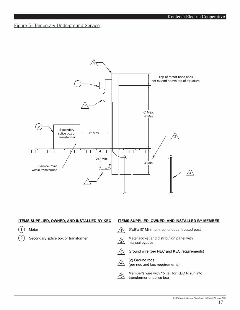
A. Equipment• The underground temporary meter post must be a continuous, single structure, 6 in. x 6 in. x 10 ft.
minimum. The temporary service must be within 6 ft. of KEC’s splice box or transformer. The trench, backfill and underground service conductors of sufficient length to reach KEC’s secondary equipment connections must be furnished by the member (see Figure 5).
• Underground service entrances to mobile homes must be mounted on a 6 in. x 6 in. x 10 ft. minimum, pressure-treated wood post or an approved manufactured steel pedestal (see Figures 8-9).
• Electrical PVC conduit must be cemented together with approved PVC cement.• Member-installed conduit, to be used by KEC, must have a pull string installed by the member. • The underground permanent meter pedestal shall be a minimum of 6 ft. from the pad mount transformer
with the meter socket facing the transformer. The meter pedestal shall be at least 6 ft. from a KEC power pole or 6 ft. from a KEC pad mounted transformer.
All Services• The member must furnish, install and maintain all required service entrance equipment (refer to Section 4).• KEC will provide the trench for underground line extensions in most cases. In the event that a member
provides their own trench, there will be additional line crew and trench inspection costs. Additional line extension costs may be incurred due to unusual conditions. These include, but are not limited to: (1) landscape replacement; (2) trenching in rock; (3) extreme conditions from frost, water, snow, terrain, etc.; (4) underground boring charges; (5) damaged materials or equipment during construction caused by the applicant (e.g., damaged conduit).
Kootenai Electric Cooperative
7KEC Electric Service Handbook, Edition #20, July 2017
• KEC will furnish, own and maintain the underground service conductor and meter and make all necessary connections.
All Services over 400 Amps• The member must furnish, install and maintain all required service entrance equipment, including the
service conductor from the service equipment to the transformers. (refer to Section 4).• KEC will furnish, install, own and maintain the meter and make all necessary connections of the member’s
service conductor to KEC’s facilities. KEC will furnish, at the member’s expense, all connectors required for connecting the member’s wire to the transformer. The member is responsible to provide KEC’s Field Technician with the secondary wire size and number of conductors.
• Contact your electrician for the number and size of conductors to be installed.
B. Underground Service Conductors• On an outside wall, service conductors may be installed in a minimum of Sch. 80 nonmetallic conduit, or
equivalent.• No plumbing PVC, plumbing fittings or LBs will be accepted on KEC’s incoming service conduit.
Underground Service Entrance above Grade Conduit Size and Requirements• 0 - 200 amps: 2 in. Sch. 80 nonmetallic conduit is required for service lengths less than 120 ft. if only
2-90 degree 24” minimum radius sweeps or less are used. Otherwise, 3 in. Sch. 80 nonmetallic conduit is required. A PVC expansion coupler is required below the meter base (see Figures 6 and 8).
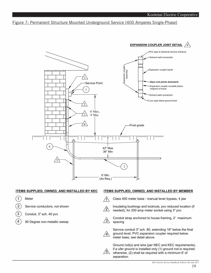
• 201 - 400 amps: A minimum of 3 in. Sch. 80 nonmetallic conduit is required. A PVC expansion coupler is required below the meter base (see Figures 7 and 10).
• Over 400 amps: Conduit and service wire will be supplied by the member. Consult your electrician for sizing.
Service Conductor ClearanceAll underground service conductors rated 600 volts or less must be buried with a minimum cover of 36 in. and maximum final grade depth of 42 in. The service conductor trench must have a minimum width of 18 in. to allow equal separation and safe working space between utilities (see Figures 6-10). If the electrical service conductor runs parallel to phone, or CATV lines, there must be a minimum of 12 in. separation. If the electrical service runs parallel to water/wastewater, there must be a minimum of 48 in. separation. When electrical service conductors cross over or under water, phone, or television lines, there should be a minimum of 12 in. of vertical separation.
C. TrenchingIn most cases, member provided trenching is not allowed. If KEC allows a member provided trench, the following guidelines must be used.• State law requires that all existing underground utilities be notified two business days in advance before
trenching begins so buried facilities can be located and marked. Locate marks are only accurate to within 24 in. of the outside dimensions of both sides of an underground facility. Excavation within that 48 in. area needs to be done in a nondestructive manner, such as hand-digging or vacuuming. One call to 811 (1.800.428.4950) will notify most existing underground utilities. KEC requires a minimum primary depth of 36 in. or additional protection measures approved by KEC will be required.
• The excavated trench must be smooth and free of any sharp objects or obstructions that may damage the conductor and/or conduit.
• 6 in. of select backfill must be used over conduit. Select backfill must be free of rocks, sharp objects, scrap

Kootenai Electric Cooperative
8KEC Electric Service Handbook, Edition #20, July 2017
building material and corrosive material. Your service will not be energized until the trench has been completely backfilled to meet code requirements.
• Backfill the remaining portion of the trench with material free of any large, sharp and corrosive objects that may damage conduits, conductors, or prevent adequate compaction of fill.
• Compact the backfill at the meter base to prevent settling of the service conductors, which may put strain on the meter base lugs. PVC expansion couplers are required below meter base.
• In a member-supplied trench shared with a water line, the minimum separation between the water line and the power line is 4 ft. horizontally and 1 ft. vertically.
• KEC will not be responsible for trench settlement in a KEC-supplied trench. • KEC will not provide the trench if it crosses the member’s driveway unless an Excavation Settlement
Liability Release form is signed. • The KEC Field Technician can provide the member a trenching spec. if member trenching is approved.
4. Metering and Service Entrance Equipment RequirementsA. Meter Seals• Meter seals are placed on meters by KEC for safety and/or tampering prevention.• All cabinets, gutters, sockets and associated devices on the line side of the meter, must have provisions for
sealing or locking by KEC. They must remain sealed at all times.• Seals must not be cut. Under normal circumstances, only KEC personnel may remove the seals. It is
the member’s responsibility to notify KEC prior to the removal of a meter for any reason. Seals may be removed only in an emergency and KEC must be notified as soon as possible thereafter.
• CAUTION: High fault current is possible when removing or installing meters under load.• CAUTION: Some types of meter bases do not de-energize the service when the meter is removed. This is
true in all current transformer installations. Removal of these meters could create a high potential resulting in a flashover.
• Any person who cuts KEC seals and/or wrongfully obtains electric service by bypassing, tampering with or modifying a meter, may be prosecuted.
• Electricians and members are not allowed to jumper meter sockets for any reason.
B. Metering Requirements• Whenever any changes or alterations are made to any electrical service, all metering must meet current KEC
standards. This includes location and equipment.• All commercial and industrial accounts must have manual lever operated bypass (These allow meter
removal while still keeping the member in power.) KEC will not accept any Manual Circuit Closing (MCC) device where jumpers are required to bypass the meter.
• All temporary power used by contractors must be metered. (The name of the persons responsible for billing must be included in the application packet.)
• Metered and non-metered circuits must not be run in the same raceway or conduit.• All meter sockets and enclosures provided by the member must be approved by KEC.• Members or contractors are not authorized to relocate any meter belonging to KEC or interfere with the
meter or its connections.• J-boxes or any deviation from the utility’s conduit from the source to the metering point will not be allowed.

Kootenai Electric Cooperative
9KEC Electric Service Handbook, Edition #20, July 2017
• For 400 amp meter bases, the member must provide set screw termination lugs large enough for 350 kcmil cable.
• Meter bases for underground services in rural areas are preferred to be installed next to the pad mount transformer. This pertains to new services in rural areas and services in low density areas (lot size 1/2 acre or greater).
• For meter bases with underground services in a low density area, the meter bases or meter pedestals are required to have a main breaker to protect the service wire from the meter base to the electrical service panel and to enable the member to de-energize their service wire if needed.
C. Meter Location• The preferred meter base location in a high density subdivision is on the transformer or splice box side of
the house within 15 ft. of the front of the house.• Meters must not be installed under any type of overhang, porch, roof, deck or similar enclosure that will
limit access to the meter. • Shrubbery and landscaping must be kept clear of the meter location.• Meters and current transformer enclosures must be installed outdoors. • Gas meters must be located at least 3 ft. horizontal distance from the electric meters.• Metering equipment must not be installed at a service switch located in an inaccessible place such as a
manhole or vault.• Multiple meters for one building with multiple tenants must be grouped at one accessible location outside.
One meter per space, each with its own disconnect, will be installed. See Section 4E for multiple meter mounting requirements.
• Meters must be protected from ice or snow sliding off of metal roofs, by extending eaves, gutters or other means and be protected from physical damage when located on member’s premises.
• Meter equipment must be located on the line side of the main disconnect.
EXCEPTION: When there are more than 6 meters, they must be located on the load side of the main disconnect, if a main disconnect is required (which must be sealable), and on the line side of the individual service switches.
Single meters must be installed 4-6 ft. from the floor or finished grade to the center of the meter box. An exception would be a single piece permanent underground metal fabricated meter base (see Figure 9). It is required that the meter base and conduit be on an outside wall and not enclosed. Flush mount meter bases are not preferred. If the member insists on a flush mount meter base then the unexposed conduit must be rigid steel conduit or schedule 80 PVC with metal shields to prevent drilling into the PVC. The shield must be at least 1/16 in. thick and made of steel. A 3 ft. radius sweep must be installed through the footing to the proper depth and pointed toward the source.
D. IdentificationWhen more than one meter is installed at one location, the installer must clearly mark each meter socket and unit in legible, permanent lettering with the correct address and the building unit number serviced by the meter.
E. Meter MountingMeter sockets and/or enclosures must be plumb, level and securely mounted to a rigid surface. All conductors must be securely fastened and must not interfere with the operations of the meter or circuit-closing device.
Kootenai Electric Cooperative
10KEC Electric Service Handbook, Edition #20, July 2017
The member must provide space for metering that is convenient to KEC, readily accessible and free from vibration, corrosive atmosphere and abnormal temperatures. If, in the opinion of KEC, a meter is made inaccessible such as by the installation of a fence or enclosure, the member must, at their expense, move the meter socket to an accessible location. KEC, at its option and at the member’s expense, will install a remote reading register or a pole meter to alleviate an accessibility problem.
Multiple meter installations or multiple meter packs shall be installed no more than 6 ft. to the center of the top meter and not less than 24 in. to the center of the bottom meter from finish grade elevation.
Ample workspace must be provided for the metering and kept clear at all times. Minimum space must be 30 in. wide with the meter centered. 36 in. minimum frontal and overhead clearances will be in accordance with the National Electric Code (NEC).
F. Specific Service InformationTemporary Services• All temporary services must be metered.• Manual lever operated bypass sockets are not required on single-phase temporary services.
Residential Single Family Dwelling• KEC will accept most UL listed meter bases up to 200 amp capacity.• Most 400 amp meter sockets will be accepted on 400 amp residential services.• Current Transformer metering may be required on some 400 amp single-phase services, at which time KEC
will provide the metering equipment as described under non-residential accounts. (KEC should be contacted for specific requirements).
Non-residential single-phase or three-phase • Lever operated manual bypass sockets are required on all 400 amp single-phase non-residential services.• Members are required to provide a manual lever operated bypass for any three-phase self-contained
metering devices rated up to 200 amps.• A seven terminal socket is required on all three-phase services where the service conductor capacity does
not exceed 200 amps. This includes the following voltages: 120/208 volt, three-phase, four-wire and 277/480 volt, three-phase, four-wire. The grounded conductor must be connected or terminated to the third terminal from the left of the lower terminals (load side of socket).
• For larger installations KEC will, upon request, furnish the available fault current at the secondary terminals of the transformer. The member’s equipment needs to be rated to handle the available fault current.
• The phase conductor of existing four-wire delta circuit with the highest voltage to ground (wild leg) must be identified in orange and must be connected to the upper extreme right terminal of the socket (line side of socket). KEC no longer accepts new three-phase delta services.
Non-residential three-phase accounts requiring instrument metering• KEC will provide the metering equipment necessary, at the member’s expense, to meter three-phase loads
exceeding 200 amps and requiring the need for current transformers. • KEC is responsible for the installation, wiring and placement of current transformers (CT) and meter sockets
for all instrument-metering applications or instrument-metering sockets, except for special CT metering cans mounted on houses.
• Most current transformers will be mounted inside pad mount distribution transformers and the CT meter will

Kootenai Electric Cooperative
11KEC Electric Service Handbook, Edition #20, July 2017
be mounted on the transformer case.• On large motor (inductive) loads, kvar metering may be required.
Meter SocketsSingle-phase sockets to be supplied by the member.• Up to 400 amps: 120/240 volt four-terminal sockets (200 amp) or (400 amp) panels.• 120 volt, two-wire service is not available.
Single-phase non-residential sockets to be supplied by the member.• 120/240 volt three-wire (single-phase 400 amp with lever actuated manual circuit closing meter socket are
required.
Three-phase non-residential sockets to be supplied by the member.• All shall be seven terminal sockets.• All three-phase non-residential sockets to be supplied by the member must have a manual level bypass.
KEC will not accept any MCC socket that requires a jumper to bypass the meter socket.
Single or three-phase non-residential Current Transformer (CT) meter sockets to be installed by KEC.• The member, depending upon the agreements between the member and KEC will pay the costs for such CT
rated equipment.• 120/240 volt three-wire over 200 amps (single-phase may require an instrument meter)• 120/208 volt four-wire over 200 amps• 277/480 volt four-wire over 200 amps• All supports for the installation of instrument metering may be furnished by the member unless other
provisions are made between KEC and the member. KEC normally furnishes the post on single-phase instrument meters.
• Variable frequency drives must meet the industry standard (IEEE Standard 519-1992) for harmonics.
G. MiscellaneousHeat Pumps• All heat pump installations are required to have capacitor starting.• Service lengths must be kept short to limit voltage flicker, typically within 20 ft. of the service entrance.• Heat pumps 4-ton and larger will require a 400 amp service and meter base.
GroundingAll meter sockets, enclosures and conduit must be bonded and grounded in accordance with Articles 230 and 250 of the latest edition of the NEC. Where self-contained meter sockets are used, the neutral conductor must be connected to the ground terminal in the socket. NEC 250-84 requires two ground rods where a single ground electrode has a resistance over 25 Ohms.
KEC requires an 8 ft. copper ground rod installed even if a concrete-encased (UFER) ground is used to provide grounding.
Fusing and ProtectionCurrent-limiting fuses to protect the member’s electrical system from high fault current must not be installed in meter sockets or instrument transformer locations. They may be installed in the member’s service panel or
Kootenai Electric Cooperative
12KEC Electric Service Handbook, Edition #20, July 2017
in a separate enclosure between the socket and the panel. The separate enclosure may be on the load side of the meter sockets in multiple meter installations if the enclosure has sealing provisions.
Backup Generators• All backup generator installations must have a transfer switch installed in accordance with the NEC.• Transfer switch installations must be inspected by the State Electrical Inspector.• The member must provide KEC with a copy of the state electrical permit for transfer switch installation and
notify KEC of generator installation.
Siding InstallationIt is the member’s responsibility to make sure that siding contractors do not install siding that will interfere with access to the meter socket, the service and/or removal of the meter or the sealing of the meter.
It is recommended that a qualified electrician be notified for the removal and remounting of the conduit and meter socket. If required, KEC must be contacted for cutting meter seals and removing the meter. (see Section 4A regarding meter seals).
5. ClearancesIn order to meet appropriate electrical and safety codes, KEC requires spacing from pad mounted equipment to buildings and underground propane tanks (see Figures 11 & 12). Consult a KEC field technician for any other clearance questions.
6. FiguresOn the following pages, we have provided all figures referenced in this handbook.
Kootenai Electric Cooperative
13KEC Electric Service Handbook, Edition #20, July 2017
24" Min. if X is less than or equal to 4 ft.or
42" Min. if X is greater than 4 ft.(Consult Field Engineer Re: guy attachment andrequired mast height)
6' Max.4' Min.
Second ground rodis not requiredif UFER ground isinstalled.
6' Min.
Figure 1: Service Conductor Installation and Clearance
NOTES: Consult Field Engineer prior to installation.
Service entrance conductors18" out of weatherhead for
KEC connection
Figure 1: Service Conductor Installation and Clearance
Kootenai Electric Cooperative
14KEC Electric Service Handbook, Edition #20, July 2017
PRIMARY OVERHEAD RIGHT-OF-WAY CLEARING REQUIREMENTS
FIGURE 2: RIGHT-OF-WAY CLEARING REQUIREMENTS
30 FT.
15 FT. 15 FT.
SECONDARY OVERHEAD RIGHT-OF-WAY CLEARING REQUIREMENTS
UNDERGROUND RIGHT-OF-WAY CLEARING REQUIREMENTS
7.5 FT. 7.5 FT.
15 FT.
6 FT.
3 FT. 3 FT.
Figure 2: Right-of-Way Clearing Requirements
Kootenai Electric Cooperative
15KEC Electric Service Handbook, Edition #20, July 2017
8' Min. (Typ)
6' Max.4' Min.
5
24" Min.
10'Min.
4
3
3
1
5
6
2
2
1
Align service drop betweenbraces. max. 50' withoutKEC approval
6' Min.
8' Min.(Typ.)
ITEMS SUPPLIED, OWNED, AND INSTALLED BY KEC
Insulated clevis
Service conductors
Meter
ITEMS SUPPLIED, OWNED, AND INSTALLED BY MEMBER
6"x6"x18' Minimum, continuous, singlestructure
Meter socket, weatherhead, mast anddistribution panel
Ground wire (per NEC and KEC requirements)
Ground rod and clamp(2 required per NEC and KEC)
(2) 2"x4" Brace
Service entrance conductors - 18" out ofweatherhead
1
2
3
1
2
3
4
5
6
FIGURE 3: TEMPORARY OVERHEAD SERVICE INSTALLATION
Service entrance conductors18" out of weatherhead
Figure 3: Temporary Overhead Service Installation
Kootenai Electric Cooperative
16KEC Electric Service Handbook, Edition #20, July 2017
Figure 4: Permanent Overhead Service Installation - Meter Base Near Service Pole
ITEMS SUPPLIED, OWNED, AND INSTALLED BY KEC
Secondary service pole
Down guy
Insulated clevis
Service conductor
Secondary conduit, and serviceentrance conductors
Anchor rod
ITEMS SUPPLIED, OWNED, AND INSTALLED BY MEMBER
meter base(see figure 8, 9, or 10 for detail)
1
2
3
1
1
75
1
2
6
34
4
5
6
6' Min.
Service Point
Figure 4: Permanent Overhead Service Installation - Meter Base Near Service Pole
Kootenai Electric Cooperative
17KEC Electric Service Handbook, Edition #20, July 2017
ITEMS SUPPLIED, OWNED, AND INSTALLED BY KEC
Meter
Secondary splice box or transformer
ITEMS SUPPLIED, OWNED, AND INSTALLED BY MEMBER
6"x6"x10' Minimum, continuous, treated post
Meter socket and distribution panel withmanual bypass
Ground wire (per NEC and KEC requirements)
(2) Ground rods(per nec and kec requirements)
Member's wire with 15' tail for KEC to run intotransformer or splice box
1
2
1
2
3
4
5
24" Min.
1
5
4
2
1
2
3
6' Max.4' Min.
3' Min.
6' Max.
FIGURE 5: TEMPORARY UNDERGROUND SERVICE
Secondarysplice box orTransformer
Top of meter base shallnot extend above top of structure
Service Pointwithin transformer
Figure 5: Temporary Underground Service

Kootenai Electric Cooperative
18KEC Electric Service Handbook, Edition #20, July 2017
ITEMS SUPPLIED, OWNED, AND INSTALLED BY MEMBER
Meter base - 4 jaw
Insulating bushing and locknuts
Conduit strap anchored to house framing, 2 on centerNote: Metallic conduit is required to be bonded
Service conduit 2" sch. 80, extending 18" belowfinal ground level. PVC expansion couplerrequired below meter base. See detail above
Ground rod(s) and wire (per NEC and KEC requirements). ifa ufer ground is installed only (1) ground rod is required. otherwise (2) shall be required with a minimum of 6' ofseparation.
1
2
3
4
5
FIGURE 6: PERMANENT STRUCTURE MOUNTED UNDERGROUND SERVICE (0-200 AMPERES SINGLE PHASE)
1
1
2
3
4
6' Max.4' Min.
3
5
4 42" Max.36" Min.
6' Min.(As Req.)
Final grade
ITEMS SUPPLIED, OWNED, AND INSTALLED BY KEC
Meter
Service conductors, not shown
Conduit, 3" sch. 40 pvc
90 Degree non-metallic sweep
1
2
3
4
Solvent weld connection
Expansion coupler barrel
Expansion coupler movable piston,midpoint of travel
Solvent weld connection
Open end points downward
To pvc pipe below ground level
PVC pipe to electrical service entrance
Expa
nsio
n co
uple
ras
sem
bly
EXPANSION COUPLER JOINT DETAIL 4
Service Point
Figure 6: Permanent Structure Mounted Underground Service (0-200 Amperes Single Phase)
Kootenai Electric Cooperative
19KEC Electric Service Handbook, Edition #20, July 2017
Figure 7: Permanent Structure Mounted Underground Service (400 Amperes Single-Phase)
ITEMS SUPPLIED, OWNED, AND INSTALLED BY KEC
Meter
Service conductors, not shown
Conduit, 3" sch. 40 pvc
90 Degree non-metallic sweep
ITEMS SUPPLIED, OWNED, AND INSTALLED BY MEMBER
Class 400 meter base - manual lever bypass, 4 jaw
Insulating bushings and locknuts, pvc reduced location (if needed), for 200 amp meter socket using 3" pvc
Conduit strap anchored to house framing, 2' maximum spacing
Service conduit 3" sch. 80, extending 18" below the final ground level. PVC expansion coupler required below meter base, see detail above.
Ground rod(s) and wire (per NEC and KEC requirements).if a ufer ground is installed only (1) ground rod is required.otherwise, (2) shall be required with a minimum 6' of separation.
1
2
3
1
2
3
4
5
1
1
2
3
4
6' Max..4' Min.
3
5
4 42" Max36" Min
6' Min.(As Req.)
Final grade
FIGURE 7: PERMANENT STRUCTURE MOUNTED UNDERGROUND SERVICE (400 AMPERES SINGLE PHASE)
4
Solvent weld connection
Expansion coupler barrel
Expansion coupler movable piston,midpoint of travel
Solvent weld connection
Open end points downward
To pvc pipe below ground level
PVC pipe to electrical service entrance
Expa
nsio
n co
uple
ras
sem
bly
EXPANSION COUPLER JOINT DETAIL 4
Service Point
Kootenai Electric Cooperative
20KEC Electric Service Handbook, Edition #20, July 2017
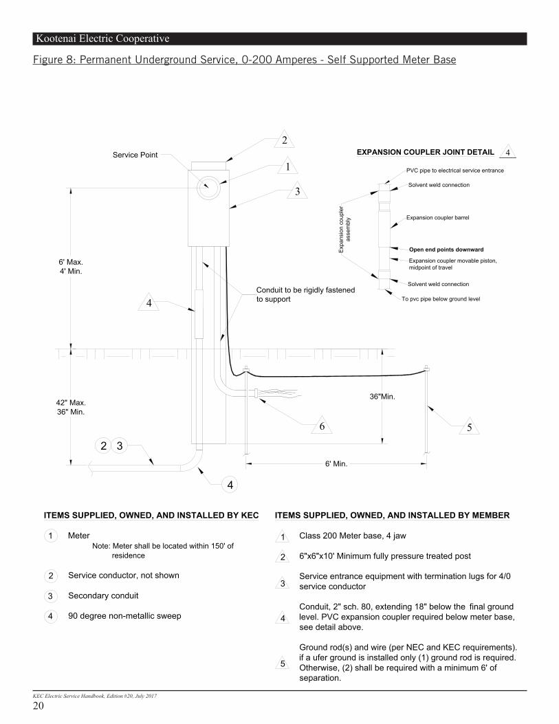
ITEMS SUPPLIED, OWNED, AND INSTALLED BY KEC
MeterNote: Meter shall be located within 150' of residence
Service conductor, not shown
Secondary conduit
90 degree non-metallic sweep
ITEMS SUPPLIED, OWNED, AND INSTALLED BY MEMBER
Class 200 Meter base, 4 jaw
6"x6"x10' Minimum fully pressure treated post
Service entrance equipment with termination lugs for 4/0 service conductor
Conduit, 2" sch. 80, extending 18" below the final ground level. PVC expansion coupler required below meter base, see detail above.
Ground rod(s) and wire (per NEC and KEC requirements).if a ufer ground is installed only (1) ground rod is required.Otherwise, (2) shall be required with a minimum 6' of separation.
Feeder conductor and conduit. (per NEC and KEC requirements)
1
2
3
1
2
3
4
5
6
4
3
2
Conduit to be rigidly fastenedto support
4
1
3
4
36"Min.
6
42" Max.36" Min.
6' Max.4' Min.
6' Min.
5
2
Solvent weld connection
Expansion coupler barrel
Expansion coupler movable piston,midpoint of travel
Solvent weld connection
Open end points downward
To pvc pipe below ground level
PVC pipe to electrical service entrance
Expa
nsio
n co
uple
ras
sem
bly
EXPANSION COUPLER JOINT DETAIL 4
FIGURE 8: PERMANENT UNDERGROUND SERVICE, 0-200 AMPERES - SELF SUPPORTED METER BASE
Service Point
Figure 8: Permanent Underground Service, 0-200 Amperes - Self Supported Meter Base
Kootenai Electric Cooperative
21KEC Electric Service Handbook, Edition #20, July 2017
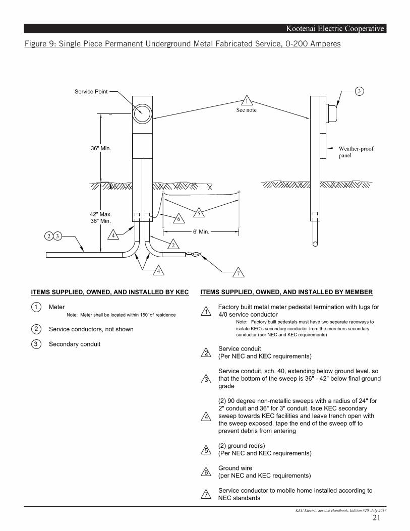
Figure 9: Single Piece Permanent Underground Metal Fabricated Service, 0-200 Amperes
ITEMS SUPPLIED, OWNED, AND INSTALLED BY KEC
MeterNote: Meter shall be located within 150' of residence
Service conductors, not shown
Secondary conduit
ITEMS SUPPLIED, OWNED, AND INSTALLED BY MEMBER
Factory built metal meter pedestal termination with lugs for4/0 service conductor
Note: Factory built pedestals must have two separate raceways to isolate KEC's secondary conductor from the members secondary conductor (per NEC and KEC requirements)
Service conduit(Per NEC and KEC requirements)
Service conduit, sch. 40, extending below ground level. sothat the bottom of the sweep is 36" - 42" below final groundgrade
(2) 90 degree non-metallic sweeps with a radius of 24" for2" conduit and 36" for 3" conduit. face KEC secondary sweep towards KEC facilities and leave trench open with the sweep exposed. tape the end of the sweep off to prevent debris from entering
(2) ground rod(s)(Per NEC and KEC requirements)
Ground wire(per NEC and KEC requirements)
Service conductor to mobile home installed according to NEC standards
1
2
3
1
2
3
4
5
6
See note
5
1
6
23
Weather-proofpanel
36" Min.
42" Max.36" Min.
3
2 4
4 7
6' Min.
FIGURE 9: SINGLE PIECE PERMANENT UNDERGROUND METAL FABRICATED SERVICE, 0-200 AMPERES
7
Service Point
Kootenai Electric Cooperative
22KEC Electric Service Handbook, Edition #20, July 2017
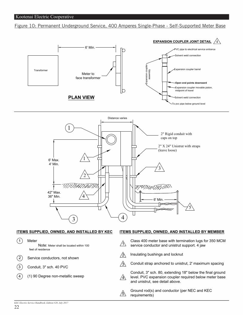
Figure 10: Permanent Underground Service, 400 Amperes Single-Phase - Self-Supported Meter Base
ITEMS SUPPLIED, OWNED, AND INSTALLED BY KEC
MeterNote: Meter shall be located within 100
feet of residence
Service conductors, not shown
Conduit, 3" sch. 40 PVC
(1) 90 Degree non-metallic sweep
ITEMS SUPPLIED, OWNED, AND INSTALLED BY MEMBER
Class 400 meter base with termination lugs for 350 MCM service conductor and unistrut support. 4 jaw
Insulating bushings and locknut
Conduit strap anchored to unistrut, 2' maximum spacing
Conduit, 3" sch. 80, extending 18" below the final ground level. PVC expansion coupler required below meter base and unistrut, see detail above.
Ground rod(s) and conductor (per NEC and KEC requirements)
Service conductor installed according to NEC standards
1
2
3
1
2
3
4
5
6
4
2" Rigid conduit withcaps on top
2" X 24" Unistrut with straps(leave loose)
3
3 4
1
1
2
42" Max.36" Min. 4
5
6' Min.
6' Max.4' Min.
FIGURE 10: PERMANENT UNDERGROUND SERVICE 400 AMPERES SINGLE PHASE SELF SUPPORTED METER BASE
Distance varies
PLAN VIEW
Transformer
6' Min.
Meter toface transformer
Solvent weld connection
Expansion coupler barrel
Expansion coupler movable piston,midpoint of travel
Solvent weld connection
Open end points downward
To pvc pipe below ground level
PVC pipe to electrical service entrance
Expa
nsio
n co
uple
ras
sem
bly
EXPANSION COUPLER JOINT DETAIL 4
Kootenai Electric Cooperative
23KEC Electric Service Handbook, Edition #20, July 2017
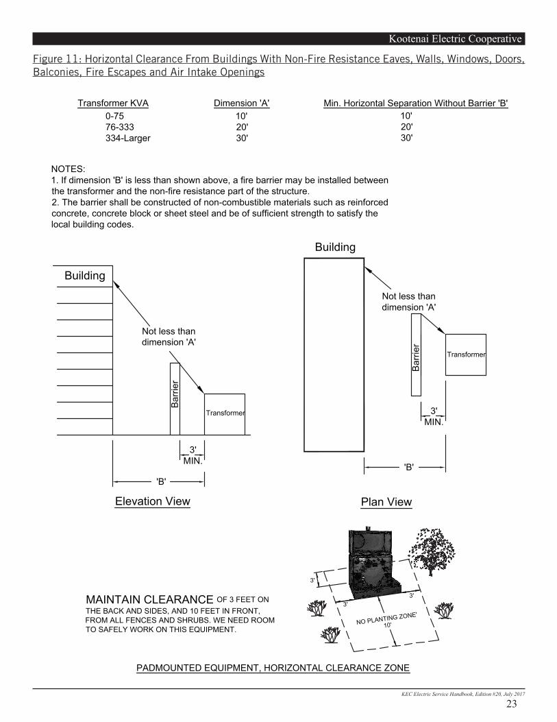
Figure 11: Horizontal Clearance From Buildings With Non-Fire Resistance Eaves, Walls, Windows, Doors, Balconies, Fire Escapes and Air Intake Openings
Dimension 'A' Min. Horizontal Separation Without Barrier 'B'Transformer KVA10'20'30'
10'20'30'
0-7576-333334-Larger
NOTES:1. If dimension 'B' is less than shown above, a fire barrier may be installed betweenthe transformer and the non-fire resistance part of the structure.2. The barrier shall be constructed of non-combustible materials such as reinforcedconcrete, concrete block or sheet steel and be of sufficient strength to satisfy thelocal building codes.
Building
Not less thandimension 'A'
Barri
er
3'MIN.
Elevation View Plan View
Barri
er
Not less thandimension 'A'
Building
FIGURE 11: HORIZONTAL CLEARANCE FROM BUILDINGS WITH NON-FIRE RESISTANCEEAVES, WALLS, WINDOWS, DOORS, BALCONIES, FIRE ESCAPES AND AIR INTAKEOPENINGS.
Transformer
Transformer
'B'
3'
10'NO PLANTING ZONE'3'
3'
PADMOUNTED EQUIPMENT, HORIZONTAL CLEARANCE ZONE
MAINTAIN CLEARANCE OF 3 FEET ONTHE BACK AND SIDES, AND 10 FEET IN FRONT,FROM ALL FENCES AND SHRUBS. WE NEED ROOMTO SAFELY WORK ON THIS EQUIPMENT.
'B'
3'MIN.

Kootenai Electric Cooperative
24KEC Electric Service Handbook, Edition #20, July 2017
Figure 12: Separation Requirements for Propane Tank Installations Near Electrical Utilities
10' 10'
10'
10'10'
10'
10'
10'
Clear Zone
10' 10'10'
10'10'
10'
Clear Zone
TOP VIEW SIDE VIEW
KEC requires that a minimum 10 foot radius be maintained around all UNDERGROUND PROPANE TANKS andany underground power lines or related above ground equipment (transformers, meters, modules, etc.)
See the above diagrams for a general guideline in the separation requirements for UNDERGROUND PROPANETANKS near electrical utility conductor and devices.
SEPARATION REQUIREMENTS FOR PROPANE TANKINSTALLATIONS NEAR ELECTRICAL UTILITIES
KEC requires that no ABOVE GROUND PROPANE TANK be permitted below overhead power lines or anyassociated electrical equipment. The required clear zone surrounding the tank must be a full 10 foot radiushorizontally, extending vertically (skyward) with no electrical encroachments of any kind.
See the above diagrams for a general guideline in the separation requirements for ABOVE GROUND PROPANETANKS near electrical utility conductor and devices.
ABOVE GROUND PROPANE TANKS
UNDERGROUND PROPANE TANKS
Figure 12: Separation Requirements for Propane Tank Installations Near Electrical Utilities
Kootenai Electric Cooperative
25KEC Electric Service Handbook, Edition #20, July 2017
7. Glossary• Approved – Acceptable to the authority having jurisdiction.• Bonded – Permanent joining of metallic parts.• Clearance – A set distance between two objects.• Conduit – A listed or approved wire way with a smooth interior surface to permit easy drawing-in of the
electrical conductors. A conduit may be metallic or nonmetallic, depending on its usage, in accordance with codes and KEC standards.
• Drip Loop – A loop formed in overhead secondary conductors at the weatherhead to prevent water from entering the service entrance conduit and equipment.
• Easement – An agreement allowing a utility to use private property for a specific purpose, such as building a distribution or transmission line.
• Enclosure – A cabinet designed for surface or flush mounting and provided with a frame, mat or trim, in which doors or removable covers are hung.
• Guying – Cables or braces used to relieve the strain of overhead conductors on masts and poles.• High Density Subdivision – A subdivision whose average lot size is less than half an acre.• High Leg – (Also wild leg, delta leg) The phase leg that is at higher potential to ground than any other two-
phase legs. This leg must be identified in orange.• Instrument Transformer – Current and/or potential transformers used in connection with metering
equipment to monitor high current loads and/or high voltage potentials. • Listed – Equipment or material accepted by a nationally-recognized testing laboratory, inspection agency,
or other organization concerned with product evaluation. Such organizations maintain periodic production inspections of listed equipment and materials and state that the items meet nationally-recognized standards, or have been tested and found suitable for use in a specific manner.
• Low Density Subdivision – A subdivision whose average lot size is one half acre or more. • Member – A person, entity or their designee who submits an application to the Cooperative requesting a line
extension or line modification. • Meter – A device used to total the amount of electrical energy consumed by a member. • Meter Equipment – Any equipment associated with measuring electric energy.• Meter Jaw – A spring-loaded receptacle installed inside a meter socket, interfacing the terminals of the
meter to the source and load conductors of the service.• Meter Pole – A pole which supports the metering equipment owned and maintained by KEC. • Meter Socket – The mounting device consisting of meter jaws, connectors and enclosure for accommodating
socket-type meters. The mounting device may be either a single socket or a trough to accommodate more than one mounting unit.
• NEC – National Electrical Code. • NESC – National Electrical Safety Code. • Neutral – The grounded conductor in a single-phase, three-wire or three-phase, four-wire system. The
service conductor that is at zero potential to ground. • Point of Attachment – The point at which KEC’s service conductors are attached to the member’s premises
by an approved insulated clevis. • Point of Delivery – The location on the member’s premises where KEC’s circuit and the member’s system
are interconnected. • Right-of-way – A strip of land owned by another party on which a utility places poles, wires, substations and
other facilities. Sometimes acquired through eminent domain. • Seal – The locking device used to secure meter and/or service entrance equipment to assure safety and
security for the unit.
Kootenai Electric Cooperative
26KEC Electric Service Handbook, Edition #20, July 2017
• SelectBackfill – Native soil or soil brought in from another area, free from sharp objects, rocks, scrap building materials and corrosive material.
• Self-Contained – In reference to meter sockets: A device designed and rated to continuously carry the entire capacity of the service entrance equipment. The maximum self-contained meter socket current rating approved by KEC is 320 amperes (also called a single-phase Class 320 A meter).
• Service Drop – The overhead conductors from KEC’s system to the member’s point of attachment. • Service Entrance Conductors – Those conductors which extend between the member’s load center and point
of delivery. Service Entrance Equipment – Service conduit, conductors, weatherhead, meter base, enclosures, service disconnect and load center.
• Service Mast – The conduit above the meter used to provide mechanical protection for the service conductors and to support the service drop from KEC’s system.
• Standards – Authorized design principles applied to engineering, construction and operation of KEC’s facilities.
• State Inspector – The qualified representative of a city of the State of Idaho or Washington who has been authorized by governmental agencies to inspect electrical service installations on their behalf.
• Temporary Service – An electrical service installed by KEC to provide power to a member on a temporary basis.
• Third Party Easement – An easement for any additional landowners on which the service point encroaches.• Trough or Gutter – An enclosure used as a raceway for metered conductors and as a terminating point for
branching to multiple loads. • UL – (Underwriters Laboratories) A nationally recognized test laboratory which lists materials it has tested
and accepted.
8. SourcesThe following national standards were used to compile the information in this booklet: ANSI 05.1 American National Standard InstituteAWPA C4 American Wood Products AssociationEUSERC Committee Electric Utility Service Equipment RequirementsNEC 200-6 Identifying Grounded ConductorsNEC 225-18 Clearance from GroundNEC 225-19 Clearances from Buildings for Conductors of not over 600 volts, nominalNEC 230 ServicesNEC 230-24 ClearancesNEC 250 GroundingNEC 300-5 Wiring Methods, Underground InstallationsNEC 310-12 Conductor IdentificationNEC 310-14 Aluminum ConductorsNEC 550-23 Mobile Home Service EquipmentNESC 422-H Current TransformersUL or Approved Testing LaboratoryNFPA-58