electric parking brake - ari...
TRANSCRIPT

NSEPB 001/11
Electric Parking BrakePARTS LIST/INSTALLATION
INSTRUCTION MANUAL
3 7 Daniel Road West, Fairfield, NJ 07004 E-mail: [email protected]: (973) 808-9709 Fax: (973) 808-9713 Web: www.drive-master.com

Mobility Dealer and Installing TechThank you for the purchase of this product.
Please familiarize yourself with theseinstructions, they have changed to reflectthe redesigned product and wiring for all vehicles.
Before starting the installation of the Drive-Master Electric Park Brake check to make surethe OEM indicator light works when engagingthe OEM emergency brake pedal. As you willbe modifying the OEM emergency brakeassembly you will also need to confirm thatwhen the emergency brake is engaged it willnot allow the vehicle to roll while in gear withthe engine running. If the vehicle has any problems related to the use of the OEM emergency brake they should be repaired before attemptingthe installation.
Please read through the installation instructions before attempting the installation.Any questions that arise during installation please call for technical
assistance (973) 808-9709 Monday-Friday 8:00 AM-4:30 PM EST.
If you follow step by step as instructed, you will not encounter diffi-culties and will have a proper installation.
Thank you for supporting Drive-Master Products.
Yours in mobility,
President
2

3

4
If your OEM dash brake light indicator stays on after thePark Brake is released and the D.M. Park Brake has beenchecked over for proper installation and wiring, you willneed to have your brake system inspected by an authorizedOEM dealer.

DRIVE-MASTER ELECTRIC PARKING
BRAKE WARRANTY
Drive-Master manufactured parts are warranted against defects in materials and workman-ship under normal use for one year from date of purchase. All parts alleged to be defectivewill be repaired or replaced at Drive-Master’s discretion. A credit memo will be issuedupon receipt of the defective part, provided: a) The invoice number of the original purchaseis supplied; b) The return is WIThIN 30 days of receipt of replacements parts; c) Thereturned merchandise is NOT modified, disassembled, or altered; and d) The part fallswithin warranty terms.
RETURN POLICY
In order to better serve you, our return authorization program for the return of merchandiseis as follows:
We will NOT accept defective or returned parts without a return authorization (RA) num-ber. In order to receive an RA number, call our shipping department and request one -make sure to have available the invoice number, date of purchase, and EXACT reason forreturning the parts. Advise as at the time whether you want the part replaced prior to ourreceipt. If so, parts will be shipped and billed to you. If you buy from us on a COD basis,parts will be shipped COD. Credit will be issued upon the defective part’s arrival at Drive-Master. The RA number should be displayed prominently on the outside of the shippingcarton, as well as on the paper work inside the carton. We will NOT pay freight beyondground shipping under any circumstances, nor will we issue credit for any parts we receivethat were: a) special orders; b) broken due to faulty installation; c) modified in any way;d) out of warranty; or e) taken apart for any reason.
Drive-Master will accept return of new, unused merchandise and will issue credit less a15% restocking charge, only if: a) The merchandise is not damaged, disassembled, or al-tered in any way; b) It is returned within 30 days of original purchase; c) It was not a spe-cial order item; and, d) The invoice number of the original purchase is supplied.
Warning: When removing defective electrical equipment, do NOT cut wire harnesses(must be disconnected). Cutting wire harnesses voids the warranty.
5

6
PARTS LISTPART #DMBKPK001 = CABLE; #DMBKPK002 = CHAIN
PARTS LIST - MECHANICAL:
1. 1 PARKING BRAKE MOTOR UNIT WITH MOUNTING BRACKET2. 1 10” CABLE WITH CABLE STOP/OR 10” CHAIN3. 1 MICRO SWITCH BRACKET4. 1 - 1/8” U-CLAMP5. 3 - 1/4” 20 X 1” GRADE 8 BOLTS, WASHERS, AND NUTS6. 2 - 4-40 X 3/4” SCREWS/NUTS/WASHERS7. 2 - #8 X 3/4” SHEET METAL SCREWS8. 1 - 5/16” x 1-1/2” FENDER WASHER9. 1 - 1 1/4”-20 x 1-1/4” CUP POINT SET SCREW10. 5/16” LOCK COLLAR11. 1 - PEDAL ARM BRACKET (TOYOTA SIENNA, HONDA ODYSSEY, CHRYLSER
T+C, or CHEVY UPLANDER)
PARTS LIST - ELECTRICAL:
1. 3’ 18 GA. YELLOW WIRE2. 3’ 18 GA, WHITE WIRE3. 3’ 18 GA. BLACK WIRE4. 6’-10 GA. RED WIRE5. 3 RED FEMALE 1/4 BLADE6. 2 RED FEMALE 3/16 BLADE7. 2 YELLOW 10 GUAGE EYE8. 1-YELLOW 3/8’ RING CONNECTOR9. 1 - YELLOW 5/16 RING CONNECTOR10. 1 - MICRO SWITCH (EXCEPT HONDA ODYSSEY)11. 1 - SPDT TOGGLE SWITCH12. 1 - RELAY HARNESS ASSEMBLY (2 RELAY)13. 1 - PREWIRED RELAY HARNESS (1 RELAY - HONDA ODYSSEY ONLY)
IF YOU HAVE ANY QUESTIONS REGARDING INSTALLATION, PLEASE CALLDRIVE-MASTER COMPANY, INC. AT 973-808-9709 8:00 AM TO 4:30 PM EST

7
1. Shown is Toyota Siena. Other foot operated parking brakes mayhave similar or different configurations. You must disassemble toremove the locking prawl. Disable the lock prawl from the OEMgear teeth of the parking brake assembly. This will allow the pedalto be depressed and returned to starting position without locking indepressed position.

8

Drill out the head of the rivet holding in the releasemechanism.
9

10

11
12
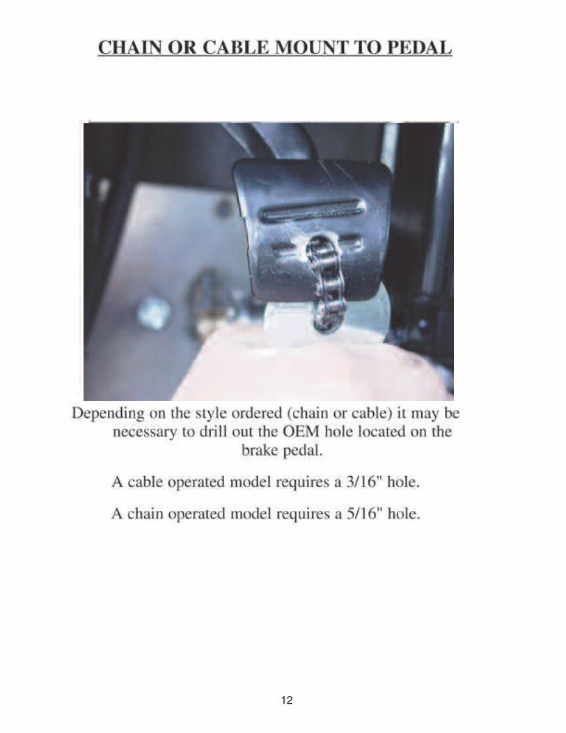
13

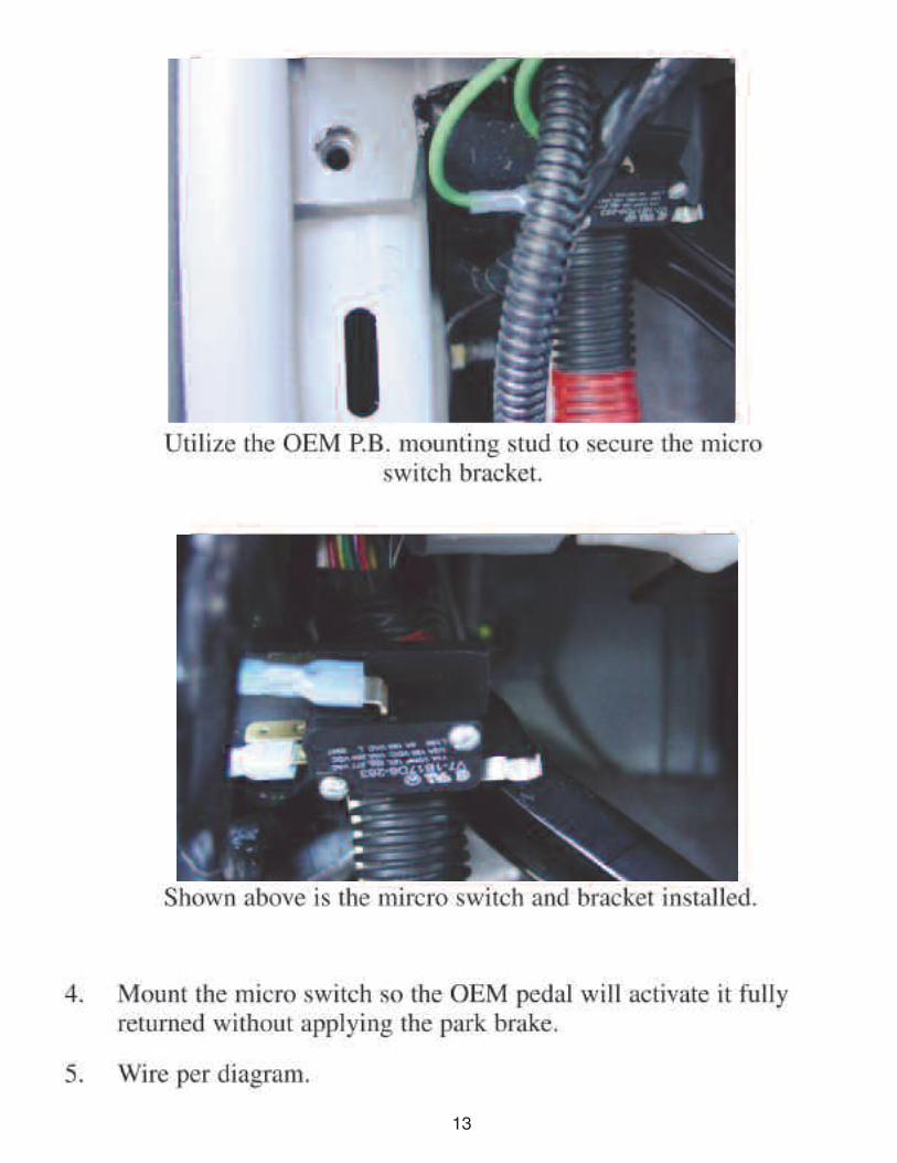
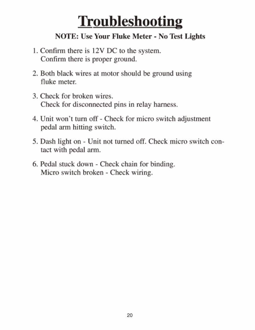
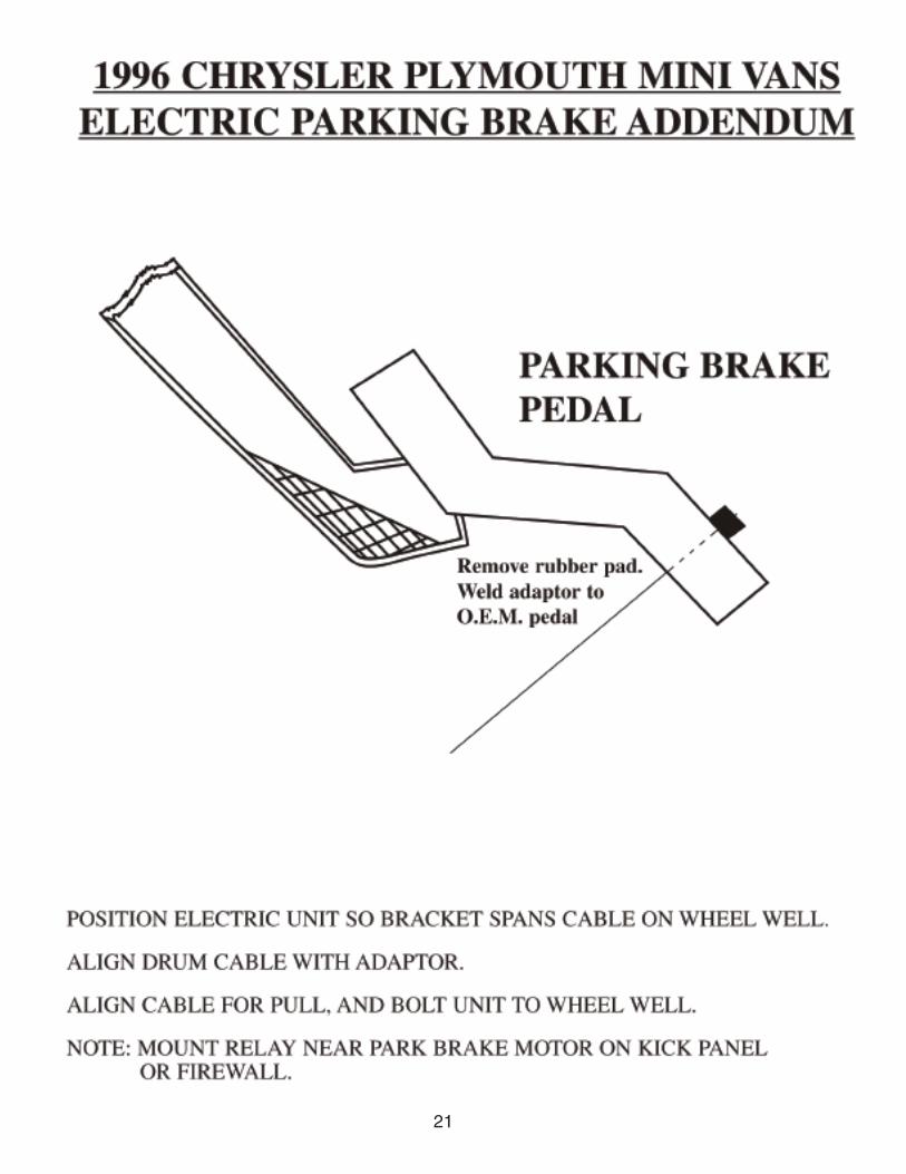
14
The picture above is shown for clarity purposes only.
Pictured above is a typical placement of the Drive-Master Park Brake as-sembly.
Toyota Only
Place Drive-Master Park Brake motor assembly just below the OEM studshown above. The mounting holes should line up vertically with the OEMstud shown above.
Line up the Park Brake assembly with the OEM park brake pedal.
Make sure the OEM park brake pedal does not contact the Park Brake as-sembly when full engaged.
The location of the toggle switch is usually determined upon fitting yourclient to the vehicle.

ALL INSTALLATIONS EXCEPT HONDA
ELECTRIC PARK BRAKEWIRING DIAGRAM
15

HONDA FULL OFF
Honda foot operated Parking Brake is released by pushing on it with your foot - you mustdisable the spring and prawl from inside the OEM Park Brake Assembly. Remove theassembly 3-OEM mounting bolts. Disassemble similar to Toyota page 7. Do this on thebench outside the car.
PARTS POSITIONING IN HONDA
Line up 2 holes on brake arm use1/4”-20x1”. Center 2nd hole over footpedal. Remove rubber pad beforedrilling.
16

HONDA FULL ON
17

86 to Parking Brake
87 GREEN
30 BLACK
WHITE 86
85 RED87
30
85 R
ED
HONDA ONLY
ELECTRIC PARK BRAKEWIRING DIAGRAM
18

19
FORD DODGE/TOTOTA/WINDSTAR HONDA
FORD DODGE/TOTOTA/WINDSTAR HONDA
MOUNTING BRACKET VARIATIONS
20
21

22

23
ThESE PhOTOS ONLY REFLECT WhAT PARTS ShOULD LOOK LIKE. PART
NUMBERS & VEhICLE INFO ShOULD BE GIVEN AT TIME OF ORDER
ALL TOYOTA SIENNAS
MICROSWITCh BRACKET P.N.#140013
PEDAL BRACKET P.N.#140076
2001-2007 DODGE CARAVAN
MICROSWITCh BRACKET P.N.# 140040
PEDAL BRACKET P.N.# 540066
FULL SIzE FORD AND ChEVY VEN-
TURE/UPLANDER MICROSWITCh
BRACKET P.N.#140039
FULL SIzE ChEVY
MICROSWITCh BRACKET
P.N.#140059
UNIVERSAL MICROSWITCh BRACKET
P.N.#140063

Dodge 2010Minivan


