parking brake and actuation - disco3.co.uk
TRANSCRIPT

Published: 11-May-2011Parking Brake and Actuation -General SpecificationItem SpecificationMake Continental TevesModel/type N5528001Operation Twin cable operation to park brake with emergency cable release located in passenger
compartmentMinimum brake lining materialthickness
2.0 mm (0.078 in)
Torque SpecificationsDescription Nm lb-ft
Wedge adjuster Allen screw 7 5Rear brake disc Torx screw 35 26Brake caliper anchor plate to wheel knuckle bolts 115 85Brake caliper to anchor plate bolts 35 26Parking brake actuator and cable assembly nuts 5 4Parking brake actuator mounting bracket bolts 22 16Fuel tank heat shield nuts 3 2Fuel tank heat shield bolts 6 4* LH/RH parking brake cable bolts 22 16Parking brake cable coupling 8 6Road wheel nuts 140 103* New nuts/bolts must be installed

Published: 11-May-2011Parking Brake and Actuation - Parking BrakeDescription and Operation
COMPONENT LOCATIONS
Item Part Number Description1 - Clutch pedal position sensor (manual transmission models only)2 - Parking brake indicators (all except NAS (north American specification))3 - Parking brake indicators (NAS only)4 - Drum brake5 - Parking brake module6 - Parking brake cable7 - Emergency release cable8 - Parking brake switch
GENERAL
The parking brake is an electrically actuated system that operates drum brakes integrated into the rear brake discs. Theparking brake system consists of:
A parking brake switch.Left and right drum brakes.Left and right brake cables.An emergency release cable.A clutch pedal position sensor (manual transmission models only).

Two parking brake indicators.A parking brake module.
The parking brake is operated by the parking brake module, which adjusts the tension of the brake cables to apply andrelease the drum brakes. Operation of the parking brake module is initiated by the parking brake switch.
PARKING BRAKE SWITCH
Item Part Number Description1 - Side stowage tray2 - Securing screw3 - Parking brake switch
The parking brake switch is used by the driver to apply and release the parking brake, and is installed in the centerconsole adjacent to the gear lever.
Slots on the sides of the parking brake switch engage with the top panel of the center console, and a screw secures theparking brake switch in position. An electrical connector on the back of the switch provides the interface with the vehiclewiring. A brake symbol on the switch illuminates when the exterior lamps are selected on.
There are three states for the parking brake switch:
Apply request, when the handle of the parking brake switch is pulled up.Release request, when the handle of the parking brake switch is pushed down.Idle, when the handle of the parking brake switch is in the central or rest position.
Microswitches, incorporated into the parking brake switch, are activated by the handle of the parking brake switch. Todetermine the operating state of the parking brake switch, the parking brake module scans the circuits containing themicroswitches.

DRUM BRAKES
• NOTE: RH brake shown, LH brake similar
Item Part Number Description1 - Brake shoe2 - Shoe locating pin and clip3 - Adjuster spring4 - Toothed wheel adjuster5 - Backplate6 - Return spring7 - Cross strut8 - Wedge adjuster screw9 - Dust shield10 - Rear brake disc11 - Adjuster access plug
Each drum brake consists of a pair of brake shoes installed on a backplate attached to the rear hub carrier. The brakeshoes operate on the drum integrated into the rear brake disc. The orientation of the brake shoes differ by 180° betweenthe left-hand (LH) and right-hand (RH) brakes.
When the parking brake module tensions the brake cables, the movement is transmitted to an operating lever on one ofthe brake shoes. The operating lever pivots against a cross strut, which forces the brake shoes apart and into contact withthe drum in the rear brake disc. Brake shoe to drum clearance is set with two manual adjusters, which are accessedthrough a hole in the brake disc. One of the adjusters is a conventional toothed wheel adjuster. The second adjuster is awedge adjuster operated by an Allen screw.
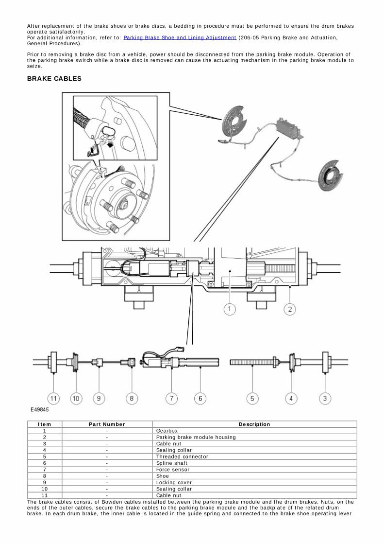
After replacement of the brake shoes or brake discs, a bedding in procedure must be performed to ensure the drum brakesoperate satisfactorily.For additional information, refer to: Parking Brake Shoe and Lining Adjustment (206-05 Parking Brake and Actuation,General Procedures).
Prior to removing a brake disc from a vehicle, power should be disconnected from the parking brake module. Operation ofthe parking brake switch while a brake disc is removed can cause the actuating mechanism in the parking brake module toseize.
BRAKE CABLES
Item Part Number Description1 - Gearbox2 - Parking brake module housing3 - Cable nut4 - Sealing collar5 - Threaded connector6 - Spline shaft7 - Force sensor8 - Shoe9 - Locking cover10 - Sealing collar11 - Cable nut
The brake cables consist of Bowden cables installed between the parking brake module and the drum brakes. Nuts, on theends of the outer cables, secure the brake cables to the parking brake module and the backplate of the related drumbrake. In each drum brake, the inner cable is located in the guide spring and connected to the brake shoe operating lever

by a nipple on the end of the cable. In the parking brake module, the two inner cables are joined together via the forcesensor and the spline shaft.
The inner cable of the RH brake cable is connected to a nipple on the force sensor by a 'shoe' on the end of the cable; alocking cover keeps the shoe engaged with the nipple.
The inner cable of the LH brake cable is connected to the spline shaft by a threaded connector (LH thread); a squaredflange at the end of the threaded connector locates in the housing of the parking brake module, to prevent the threadedconnector from turning with the spline shaft.
When the spline shaft turns, the threaded connector of the LH brake cable is screwed into or out of the spline shaft, whichchanges the effective length of the inner cables and operates the drum brakes. The ability of the spline shaft to moveaxially in the gearbox equalizes the load applied by the inner cables to the two drum brakes.
Prior to disconnecting a brake cable, power should be disconnected from the parking brake module. Operation of theparking brake switch while a brake cable is disconnected can cause the actuating mechanism in the parking brake moduleto seize. In addition, the parking brake may not switch off until 20 minutes after Power mode 0 selected. Automaticre-apply cannot be eliminated until this period has expired.
EMERGENCY RELEASE CABLE
Item Part Number Description1 - Pull ring2 - Quick release fitting3 - Parking brake module4 - Sealing collar5 - Spring

6 - Inner cable7 - Nipple8 - Pulley wheel
The emergency release cable allows the parking brake to be mechanically released if:
The parking brake cannot be electrically released because of a system fault.The battery is disconnected or battery voltage decreases below 7.5 volts while the parking brake is applied, so thatthe parking brake cannot be electrically released.
The parking brake is mechanically released by disconnecting the force sensor from the spline shaft in the parking brakemodule. During normal operation, the force sensor and the spline shaft are locked together by a lever operated pawl onthe end of the spline shaft, which engages with a spigot on the force sensor.
The emergency release cable is a Bowden cable installed between the parking brake module and the center console. Theemergency release cable is held in clips along the underside of the vehicle and enters the passenger compartment belowthe center console through an aperture in the transmission tunnel. A quick release fitting seals the emergency releasecable in the aperture. At the parking brake module, a sealing collar on the outer cable is a push fit in the housing of theparking brake module.
In the center console, a pull ring is installed on the end of the inner cable. The pull ring is designed to fit the hook on theend of the jack handle which, in combination with a screwdriver shaft, can be used to pull on the cable.
The pull required to release the latch is approximately 200 N (45 lbf). When the pull ring of the emergency release cable isreleased, the spring in the parking brake module retracts the inner cable and the nipple moves away from the pawloperating lever.
After the emergency release cable has been used to release the parking brake, the next time an apply selection is madewith the parking brake switch, the parking brake module automatically runs through a latching procedure to reconnect thespline shaft with the force sensor. The parking brake module turns the spline shaft so that it moves towards the forcesensor. The pawl of the spline shaft then re-engages with the spigot of the force sensor. A second apply selection with theparking brake switch is required to apply the parking brake.
CLUTCH PEDAL POSITION SENSOR (MANUAL TRANSMISSION MODELS ONLY)
Item Part Number Description1 - Clutch master cylinder2 - Electrical connector3 - Clutch pedal position sensor
The clutch pedal position sensor supplies a signal of clutch pedal position to the parking brake module.
The clutch pedal position sensor is a Hall effect sensor which is attached to the side of the clutch master cylinder. Theposition of the piston in the clutch master cylinder effects a magnetic field in the sensor, and is translated by the sensorinto an analogue voltage signal for the parking brake module. The parking brake module relates the signal to the positionof the clutch pedal.
PARKING BRAKE INDICATORS

Item Part Number Description1 - Red warning indicator (all except NAS)2 - Amber warning indicator (all except NAS)3 - Red warning indicator (NAS only)4 - Amber warning indicator (NAS only)
The parking brake has two warning indicators, one amber and one red, located in the speedometer of the instrumentcluster.
Amber Parking Brake Warning Indicator
The amber parking brake warning indicator is continuously illuminated if there is a parking brake system fault. Operation ofthe indicator is controlled by a high speed controller area network (CAN) bus signal from the parking brake module to theinstrument cluster.
Red Parking Brake Warning Indicator
When the parking brake is applied, the red parking brake warning indicator is continuously illuminated while the ignition ison and for 3 minutes after the ignition is switched off. If the system is unable to comply with an apply or release request,due to a system fault, the indicator flashes.
When the ignition is on and the indicator is not flashing, operation is controlled by a high speed CAN bus signal. When theignition is off or when the indicator is flashing, operation is controlled by a hardwired signal from the parking brake moduleto the instrument cluster.
Text Messages
On vehicles with the high line instrument cluster, when there is a fault condition, illumination of the warning indicators isaccompanied by a text message displayed in the message center.For additional information, refer to: Information and Message Center (413-08 Information and Message Center, Descriptionand Operation).
PARKING BRAKE MODULE
The parking brake module monitors external and internal inputs and adjusts the tension of the brake cables to operate thedrum brakes and provide the required parking brake function.
The parking brake module is installed on a support bracket attached to the front of the spare wheel carrier. Two rubbermounts, installed on lugs on the underside of the parking brake module, locate in holes in the support bracket. The topcorners of the parking brake module are secured to the support bracket with rubber mounts and flanged nuts.
The main components of the parking brake module are:
A PCB (printed circuit board) incorporating the ASIC (application specific integrated circuit) for control of the parkingbrake.An electric motor.A gearbox.A spline shaft.A force sensor.
The spline shaft and the force sensor are connected together by a latch on the end of the spline shaft. The spline shaftrotates on the latch and moves axially in the gearbox. The latch and the force sensor slide in a channel in the body of theparking brake module.
To apply or release the drum brakes, the parking brake module runs the electric motor, which drives the gearbox. Thegearbox turns the spline shaft to increase or decrease the tension in the brake cables. The parking brake module monitorsthe load exerted by the brake cables using the input from the force sensor.
Interior of Parking Brake Module

Item Part Number Description1 - Electrical connector2 - Housing3 - Electric motor4 - PCB5 - Spline shaft6 - Gearbox7 - Force sensor
Inputs and Outputs
A 32 pin electrical connector on the RH side of the parking brake module provides the interface between the PCB and thevehicle wiring.
The parking brake module is powered by two permanent battery power feeds from the battery junction box (BJB). Twoconnections with the central junction box (CJB) provide battery voltage signals in Power mode 0 and Power mode 6. Otherhardwired inputs consist of those from the parking brake switch and, on manual transmission models, the clutch pedalposition sensor.
In addition to the hardwired connections, the parking brake module is connected to the high speed CAN bus to enablecommunication with other vehicle systems.
Parking Brake Module Harness Connector C2178
Parking Brake Module Harness Connector C2178 Pin DetailsPin No. Description Input/Output
A1 Not used -A2 High speed CAN bus low out Input/OutputA3 High speed CAN bus high in Input/Output

Pin No. Description Input/OutputA4 High speed CAN bus low in Input/OutputB1 Not used -B2 High speed CAN bus high out Input/OutputB3 Parking brake switch SW1 InputB4 Parking brake switch SW4 InputC1 and C2 Not used -C3 Parking brake switch SW2 InputC4 Parking brake switch SW5 OutputD1 to E1 Not used -E2 Clutch pedal position sensor ground InputE3 Clutch pedal position sensor signal InputE4 Clutch pedal position sensor power supply OutputF1 Not used -F2 Not used -F3 Ignition power supply InputF4 Red parking brake indicator OutputG1 Not used -G2 Ground OutputG3 Not used -G4 Battery power supply InputH1 Not used -H2 Ground OutputH3 Not used -H4 Battery power supply Input
PARKING BRAKE OPERATION
The parking brake can be applied at any time provided sufficient battery power is available. For the parking brake to bereleased, various pre-conditions are required. The parking brake has manual and automatic operating modes, to cater fordifferent operating circumstances, as detailed in the following table:
Operating ModesMode Pre-Conditions Driver Action
Static apply Vehicle speed less than 2.5 km/h (1.6 mph). Pull up parking brake switch.Static release 1. Vehicle speed less than 2.5 km/h (1.6 mph).
2. Engine running.ORIgnition is ON and brake pedal or clutch pedalpressed (manual transmission).ORIgnition is ON and brake pedal or accelerator pedalpressed (automatic transmission).
Press down parking brake switch.
Ignition OFF apply 1. Vehicle speed less than 10 km/h (6.25 mph).2. Ignition is OFF.3. Selector lever is not in position 'P'. (automatictransmission).
Switch the ignition OFF.
Igniton OFF apply inhibit 1. Vehicle speed less than 2.5 km/h (1.6 mph).2. Ignition is OFF.3. Selector lever is not in position 'P'. (automatictransmission).
Switch the ignition OFF whilepressing down parking brake switch.
Dynamic apply Vehicle speed more than 2.5 km/h (1.6 mph). Pull up parking brake switch asrequired.
Dynamic release Vehicle speed more than 2.5 km/h (1.6 mph). Release (to neutral position) orpress down parking brake switch.
DAR (drive away release)(automatic transmission only)
1. Ignition is ON.2. Transmission in gear 1, 2 or R (with high rangeselected) or 1, 2, 3 or R (with low range selected).3. Accelerator pedal pressed more than 2%.4. Seatbelt is fastened.5. Drivers door is closed.
None. Parking brake releasedautomatically on drive away.
Operating Voltages
Actuation of the parking brake (apply or release) is only started if the power supply to the parking brake module is within 9to 18 volts. At any voltage in this range, the parking brake module is able to tighten the brake cables to the maximum, tofully apply the parking brake, although at voltages between 9 and 10.5 volts the actuation time may exceed 1.0 second.
During a parking brake actuation:
If the power supply to the parking brake module decreases to less than 8.3 volts, the parking brake modulecontinues the actuation, but stores a related fault code. If the ignition is on, the parking brake module also signalsthe instrument cluster to illuminate the amber parking brake warning indicator and flash the red parking brakewarning indicator. On vehicles with the high line instrument cluster, a message advising there is a parking brakefault is shown in the message center. The warning indications are discontinued if the power supply voltageincreases to 8.3 volts or more.If the power supply voltage decreases to less than 7.5 volts, the parking brake module discontinues the actuation.Actuation is automatically resumed if the power supply voltage subsequently increases to 7.5 volts or more and theparking brake switch request is still valid.If the power supply voltage decreases below 6.5 volts, the parking brake function is disabled for the remainder ofthe ignition cycle.If the power supply voltage increases to more than 18.0 volts, the parking brake module immediately disables the

parking brake function and stores a related fault code. If the ignition is on, the parking brake module also signalsthe instrument cluster to illuminate the amber parking brake warning indicator and flash the red parking brakewarning indicator. On vehicles with the high line instrument cluster, a message advising that the parking brake hasa fault and is not functioning is shown in the message center. The parking brake function remains disabled until thepower supply voltage is within 9 to 18 volts again. When the power supply voltage is within 9 to 18 volts again,the warning indications are cancelled and actuation is automatically resumed if the parking brake module is in adynamic mode of operation with a valid parking brake switch request.
• NOTE: The instrument cluster shuts down below 8 volts, so warning indications and messages are not displayed below 8volts. CAN transmission stops if battery voltage drops below 7.0 volts and re-starts when voltage goes above 7.5 volts.
Sleep Mode
To reduce quiescent drain on the vehicle battery, the parking brake module incorporates a sleep mode. The parking brakemodule enters the sleep mode, provided the ignition is off and there are no signals from the wheel speed sensors, whenone of the following occurs:
20 minutes elapse after the last actuation of the parking brake.If no actuation occurred, 20 minutes elapse after the ignition is switched off.
The parking brake module wakes up from the sleep mode when on of the following occurs:
An apply or release request is made with the parking brake switch.The ignition is switched on.A key out apply is activated.
The parking brake module wakes up within 500 ms. The high speed CAN bus is activated within 200 ms maximum.
When the parking brake module is woken with a release request from the parking brake switch, the parking brake moduleignores the request but illuminates the red brake warning indicator. The parking brake module extinguishes the red brakewarning indicator and goes back to sleep immediately the switch is released to the neutral position.
When the parking brake module is woken with an apply request from the parking brake switch, if the parking brake isalready applied the parking brake module ignores the request but illuminates the red brake warning indicator. The parkingbrake module extinguishes the red brake warning indicator and goes back to sleep immediately the switch is released tothe neutral position. If the parking brake is in the released condition when the apply request is made, the parking brakemodule illuminates the red brake warning indicator and applies the parking brake. The parking brake module extinguishesthe red brake warning indicator and goes back to sleep 3 minutes after the apply activation, or immediately after theswitch is released to the neutral position, whichever occurs last.
Dynamic Apply
In the dynamic apply mode, if the vehicle speed is more than 10 km/h (6.25 mph) when the parking brake switch isselected to apply, the parking brake module requests the ABS module to activate the disc brakes on all four wheels. Whenthe vehicle comes to a standstill, the parking brake module statically applies the parking brake. Once the static load isachieved, the hydraulic pressure is removed. If the parking brake switch is released to the neutral position, or presseddown to the release position, during dynamic apply, braking is cancelled.
The anti-lock brake system (ABS) module monitors the deceleration rate using the wheel speed sensor signals, andadjusts the hydraulic pressure to the disc brakes as required to achieve the required rate. All of the anti-lock control -traction control system brake functions remain enabled in the dynamic apply mode.
The parking brake module incorporates two fallback functions for the dynamic apply mode.
Fallback 1 is invoked if vehicle speed is between 2.5 km/h (1.25 mph) and Vmax when the parking brake switch isselected to apply and the ABS module is unable to fulfil a hydraulic request. When fallback 1 is invoked, theparking brake module decelerates the vehicle, using only the parking brake. The parking brake module monitors thedeceleration rate using the wheel speed information from the ABS module, and adjusts the tension of the brakecables to achieve the required rate. During deceleration the parking brake module also uses the wheel speed inputsfrom the ABS module to operate an anti-lock function for the rear wheels. When vehicle speed decreases to 2.5km/h (1.25 mph) the parking brake module switches to the static apply mode.Fallback 2 is invoked if there is a loss of communication between the parking brake module and the ABS module orthe CAN bus has failed. When fallback 2 is invoked, the parking brake module decelerates the vehicle using onlythe parking brake. The parking brake module tightens the brake cables under the control of the driver, no anti-lockfunction is available.
While dynamic apply is active, including fallback 1 and fallback 2, the parking brake module also outputs high speed CANbus signals to:
The ABS module, to apply the stoplamps.The instrument cluster, to sound an intermittent warning buzzer, at 0.5 second on, 1.0 second off.The instrument cluster, to illuminate the red parking brake warning indicator. The indicator is permanentlyilluminated except in fallback 2, when it flashes.
DAR Pre-arming
The DAR pre-arming function operates when the transfer box is in high range to reduce the parking brake release timeduring DAR and to provide a smooth take-off. DAR pre-arming is invoked when:
The ignition is ON.The transmission is in gear 1, 2 or R.The vehicle is stationary.No failsafe tighten actuation has occurred.
Automatic Load Adjustment

While the ignition is on, the parking brake module constantly monitors the input from the force sensor. If the tension ofthe brake cables goes outside the limits for a given operating mode, the parking brake module automatically restores thetension within limits.
Failsafe Tighten. If, during pre-arming, the vehicle moves, then the maximum cable force is reinstated for the remainderof that ignition cycle.
Automatic Apply. While the parking brake is applied, if the tension of the brake cables decreases by a prescribed amountfrom the initial setting, the parking brake module automatically restores the tension to the initial setting.
Automatic Release. While the parking brake is released, if the tension of the brake cables increase to a prescribedamount, the parking brake module automatically reduces the tension to zero.
Parking Brake Switch Monitoring
The parking brake module monitors for the following types of fault in the parking brake switch system. If a fault isdetected, the parking brake module stores a related fault code:
Short circuits between a pull-down transistor in the parking brake module and battery voltage.Broken wires and microswitches.Plausibility.
The parking brake switch has a degree of in-built redundancy. If a single microswitch fault is detected the parking brakemodule can still determine the operating state of the parking brake switch. Short circuits or multiple failures cause theparking brake module to disable the parking brake switch for the remainder of the ignition cycle. The parking brake modulealso disables the parking brake switch if a plausibility fault occurs. However, since plausibility faults are usually caused byincomplete operation of the parking brake switch, the parking brake switch is re-enabled if the parking brake modulesubsequently establishes a plausible operating state.
If a single microswitch fault is detected, the parking brake module signals the instrument cluster to illuminate the amberparking brake warning indicator. On vehicles with the high line instrument cluster, the parking brake module also signalsthe instrument cluster to display a message advising there is a parking brake fault. During an apply actuation, the parkingbrake module also signals the instrument cluster to flash the red parking brake warning indicator.
For all other fault types, the parking brake module signals the instrument cluster to illuminate the amber parking brakewarning indicator, and, on vehicles with the high line instrument cluster, to display a message advising the parking brakehas a fault and is not functioning. If it makes an apply actuation, the parking brake module signals the instrument clusterto flash the red parking brake warning indicator for the remainder of the ignition cycle.
On the next ignition cycle, the warning indicators and the messages are only activated if the fault is still present, althoughthe fault code is retained by the parking brake module until cleared by T4.
CONTROL DIAGRAM
• NOTE: A = Hardwired connection; D = High speed CAN bus; N = Medium speed CAN bus

Item Part Number Description1 - Battery2 - Fusible link 17E, BJB3 - Fusible link 8E, BJB4 - Air suspension control module5 - Diagnostic socket6 - Instrument cluster7 - Integrated head unit8 - Parking brake module

9 - automatic temperature control (ATC) module10 - Tire Pressure Monitoring Module (TPMM)11 - Parking Aid module12 - CJB module13 - Transfer box control module14 - engine control module (ECM)15 - Rear differential control module16 - ABS module17 - transmission control module (TCM)18 - Clutch pedal position sensor19 - restraints control module (RCM)20 - Parking brake switch21 - Fuse 9P, CJB (ignition)22 - Ignition push button

Published: 11-May-2011Parking Brake and Actuation - Parking BrakeDiagnosis and Testing
Principles of Operation
For a detailed description of the Parking Brake System and operation, refer to the relevant Description and Operationsection of the workshop manual.REFER to: Parking Brake (206-05 Parking Brake and Actuation, Description and Operation).
Inspection and Verification
• CAUTIONS:
Diagnosis by substitution from a donor vehicle is NOT acceptable. Substitution of control modules does notguarantee confirmation of a fault and may also cause additional faults in the vehicle being checked and/or the donorvehicle.
Please note this is a sealed unit and no attempt must be made to open the actuator as it will invalidate anywarranty claim.
• NOTE: Check and rectify basic faults before beginning diagnostic routines involving pinpoint tests.
1. Verify the customer concern.1.
2. Visually inspect for obvious signs of mechanical or electrical damage.2.
Visual InspectionMechanical Electrical
Parking brake cable(s) condition and installationParking brake shoes condition and fitmentParking brake drums (integrated into rear brake discs)Parking brake actuator module condition and installation
Parking brake indicatorsFusesWiring harness/electrical connectors
- Check for bent/corroded pinsController Area Network (CAN) circuitsParking brake switchParking brake actuator module
3. If an obvious cause for an observed or reported concern is found, correct the cause (if possible) beforeproceeding to the next step.
3.
4. If the cause is not visually evident, verify the symptom and refer to the Symptom Chart, alternatively check forDiagnostic Trouble Codes (DTCs) and refer to the DTC Index.
4.
Symptom Chart
Symptom Possible Causes ActionParking brake will notengage or release
Parking brake cablesfouled, trapped ordamagedParking brake cablesincorrectly routed or fixedParking brake shoes,linings worn/contaminatedParking brake drums(integrated into rear brakediscs)Parking brake shoesincorrectly adjustedfollowing replacementParking brake actuatormodule malfunction
Check the parking brake cables for fouling, trapping ordamage. Check the cables for correct routing. Check that thecable end fitting connector(s) are correctly fitted to theoperating lever(s). Inspect the parking brake shoes and drumsfor condition/wear/contamination,REFER to: Rear Disc Brake (206-04 Rear Disc Brake,Description and Operation) /Parking Brake Shoes (206-05, Removal and Installation).Check the parking brake shoes for correct adjustment.REFER to: Parking Brake Shoe and Lining Adjustment (206-05Parking Brake and Actuation, General Procedures).Check the operation of the parking brake actuator module,check for damage and/or excessive noise during operation.Check for parking brake actuator module DTCs.
Low parking brakeefficiency/parking brakesticking/binding
DTC Index
For a complete list of all Diagnostic Trouble Codes (DTCs) that could be logged on this vehicle, please refer to Section100-00.REFER to: Diagnostic Trouble Code (DTC) Index (100-00, Description and Operation).
Brake Bedding Mode
Bedding mode is a special mode available in the parking brake module (PBM) that disables the stability assist system(ABS) and allows the parking brake to provide the braking force rather than the conventional braking system whilst thevehicle is moving at a velocity of >3kph. This mode is entered via a series of brake pedal presses and switch applications,full details on this procedure is available in the relevant section of the workshop manual. If brake bedding mode is enteredaccidentally by the driver the RED warning lamp will flash in the Instrument Pack, the module will return to normaloperational mode when the ignition has been cycled. This DTC (C1104-68) is intended to highlight the fact that althoughthe RED lamp was illuminated there was no fault present in the control module.

Drive Cycles
Drive Cycle 1 Description
Ignition OnMake sure that no parking brake activation (diagnostic command or switch input) is attempted for a minimum of 3secondsRetest for functionality
Drive Cycle 2 Description
Ignition OnDrive vehicle at a constant speed of 20KPH (13MPH) or slightly above in 2nd gearAt a constant speed of 20KPH (13MPH) or slightly above apply the parking brake via the parking brake switchPress the brake pedal
Drive Cycle 3 Description
Ignition OnMake sure that the vehicle is stationary and that the parking brake is releasedPull the parking brake switch to the apply position and hold in this position until the parking brake motor hasstopped (this may take up to 5 seconds)Release the parking brake switch to the idle position, leave in the idle position for 2 secondsPush the parking brake switch to the release position (while pressing the brake pedal) and keep in this positionuntil the parking brake motor has stopped (this may take up to 5 seconds)Release the parking brake switch to the idle position

Published: 11-May-2011Parking Brake and Actuation - Parking Brake Shoe and Lining AdjustmentGeneral Procedures
• NOTE: This procedure must be carried out if, new parking brake shoes are fitted, new rear brake discs are fitted or if thevehicle has been mud wading (not water) for more than 50 miles.
1. Check the parking brake for correct operation.
2. CAUTIONS:
When the vehicle is in the mounting position a red flashinglight may appear on the instrument cluster. This indicates thatthe parking brake actuator is in the mounting position. It doesnot indicate a vehicle fault.
The warning lamp on the instrument cluster will flashwhilst the parking brake is being driven into the mountingposition.
Using the Land Rover approved diagnostic system, drive theparking brake to the mounting position.
3. WARNING: Do not work on or under a vehicle supportedonly by a jack. Always support the vehicle on safety stands.
Raise and support the vehicle.4. Remove the wheels and tires.
5. NOTE: Align the access hole with the indicators located onthe back plate.
Locate the parking brake shoe adjuster.
Remove the access plug.
Rotate the brake disc.
6. CAUTION: Failure to follow this step may cause damageto the parking brake system. Failure to displace the parkingbrake shoes, as shown, will result in incorrect clearance whencarrying out the adjustment step.
• NOTE: The movement of the parking brake shoe will be smalland may not be felt when levering.
• NOTE: LH shown.
Using a flat blade screwdriver, lever the brake shoes asindicated.
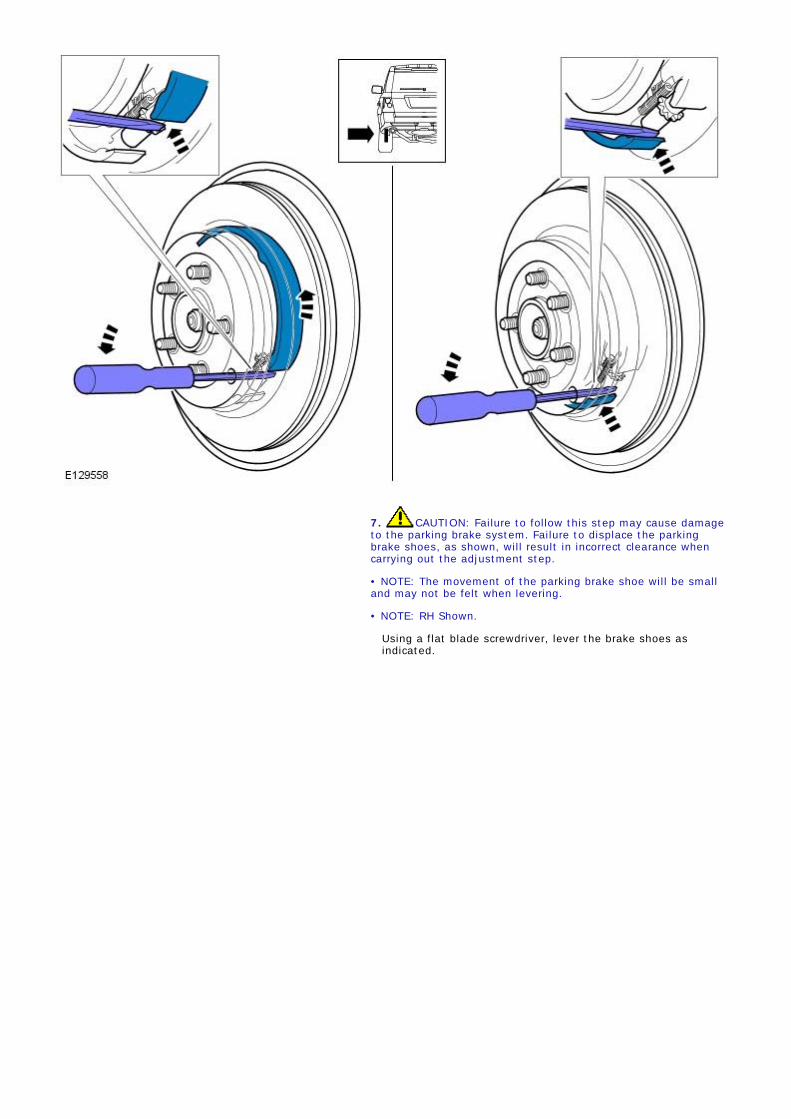
7. CAUTION: Failure to follow this step may cause damageto the parking brake system. Failure to displace the parkingbrake shoes, as shown, will result in incorrect clearance whencarrying out the adjustment step.
• NOTE: The movement of the parking brake shoe will be smalland may not be felt when levering.
• NOTE: RH Shown.
Using a flat blade screwdriver, lever the brake shoes asindicated.

8. CAUTION: Do dot apply excessive force on the brakeshoe adjuster. Failure to follow this instruction may result indamage to the parking brake system
Using a flat bladed screwdriver rotate the brake shoeadjuster to extend it until the brake disc is locked handtight.

9. CAUTION: The following steps sets the runningclearance for the parking brake shoes, failure to adhere to thepaint marking process may cause damage to the park brakesystem when the adjustment steps are carried out.
Using suitable marker, mark the position of the brake shoeadjuster.
10. CAUTION: The parking brake adjuster must be rotatedback EXACTLY one full revolution. Failure to follow thisinstruction may result in damage to the parking brake system.
Rotate the adjuster back one revolution until paint mark isvisible.
11. CAUTION: The wedge adjuster must be correctlyseated to make sure the parking brake cable is correctlyadjusted. Failure to follow this instruction may result indamage to the parking brake system.
Loosen the wedge adjuster Allen screw half a turn.
Tap the brake disc lightly with a soft faced mallet,around the parking brake shoe location within the brakedisc.
Tighten the wedge adjuster Allen screw to 6 Nm (5lb.ft).
Install the access plug.
12. Repeat the above procedure for the other side.13. Take the vehicle out of the mounting position by operating
the parking brake twice.
14. CAUTION: If the parking brake shoes or the brake discshave been removed for access to other components then DO NOTcarry out this procedure.
Carry out the parking brake shoe bedding-in procedure.For additional information, refer to: Parking Brake ShoesBedding-In (206-05 Parking Brake and Actuation, GeneralProcedures).

Published: 11-May-2011Parking Brake and Actuation - Parking Brake Shoes Bedding-InGeneral Procedures
• NOTE: This procedure must be carried out if, new parking brake shoes are fitted, new rear brake discs are fitted or if thevehicle has been mud wading (not water) for more than 50 miles.
1. Carry out the parking brake shoe bedding-in procedure.2. NOTE: The electronic parking brake 'Service Bedding-inProcedure mode' will be active for the remainder of the igntioncycle, or until the vehicle speed exceeds 31 mph (50 kph). If theprocedure needs to be re-entered, the entry actions must berepeated.
To enter 'Service Bedding-in Procedure' mode.
Start and run the engine.
Apply the footbrake 3 times within 10 seconds and holdapplied after the 3rd application.
Apply the electronic parking brake switch 4 times,followed by 3 release applications within 10 seconds.
3. Once the Service Bedding-in procedure mode has beenentered, the electronic parking brake linings can be bedded-inby conducting 10 repeated stops from 30 - 35 kph (19 - 22mph), followed by a 500 metre (547 yard) interval betweeneach stop to allow the brakes to cool, using the electronicparking brake control switch.
The electronic parking brake brake force will be increasedup to the dynamic maximum so long as the switch is heldin the applied position.
If the switch is released to either the NEUTRAL or OFFpositions, the electronic parking brake will be released.
The electronic parking brake MUST be allowed to coolbetween applications, either by driving at 19 mph (30kph) for 500 metres (547 yards) or remaining stationaryfor 1 minute between each application.
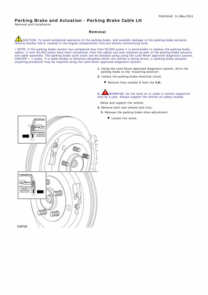
Published: 11-May-2011Parking Brake and Actuation - Parking Brake Cable LHRemoval and Installation
Removal
CAUTION: To avoid accidental operation of the parking brake, and possible damage to the parking brake actuator,remove Fusible link 8, located in the engine compartment fuse box before commencing work.
• NOTE: If the parking brake system has completed less than 50,000 cycles it is permissible to replace the parking brakecables. If over 50,000 cycles have been completed, then the cables can only replaced as part of the parking brake actuatorand cable assembly. The parking brake cycle count can be checked using using the Land Rover approved diagnostic system,(ON/OFF = 1 cycle). If a cable breaks or becomes detached whilst the vehicle is being driven, a 'parking brake actuatorunjaming procedure' may be required using the Land Rover approved diagnostic system.
1. Using the Land Rover approved diagnostic system, drive theparking brake to the 'mounting position'.
2. Isolate the parking brake electrical circuit.
Remove fuse number 8 from the BJB.
3. WARNING: Do not work on or under a vehicle supportedonly by a jack. Always support the vehicle on safety stands.
Raise and support the vehicle.4. Remove both rear wheels and tires.
5. Release the parking brake shoe adjustment.
Loosen the screw.

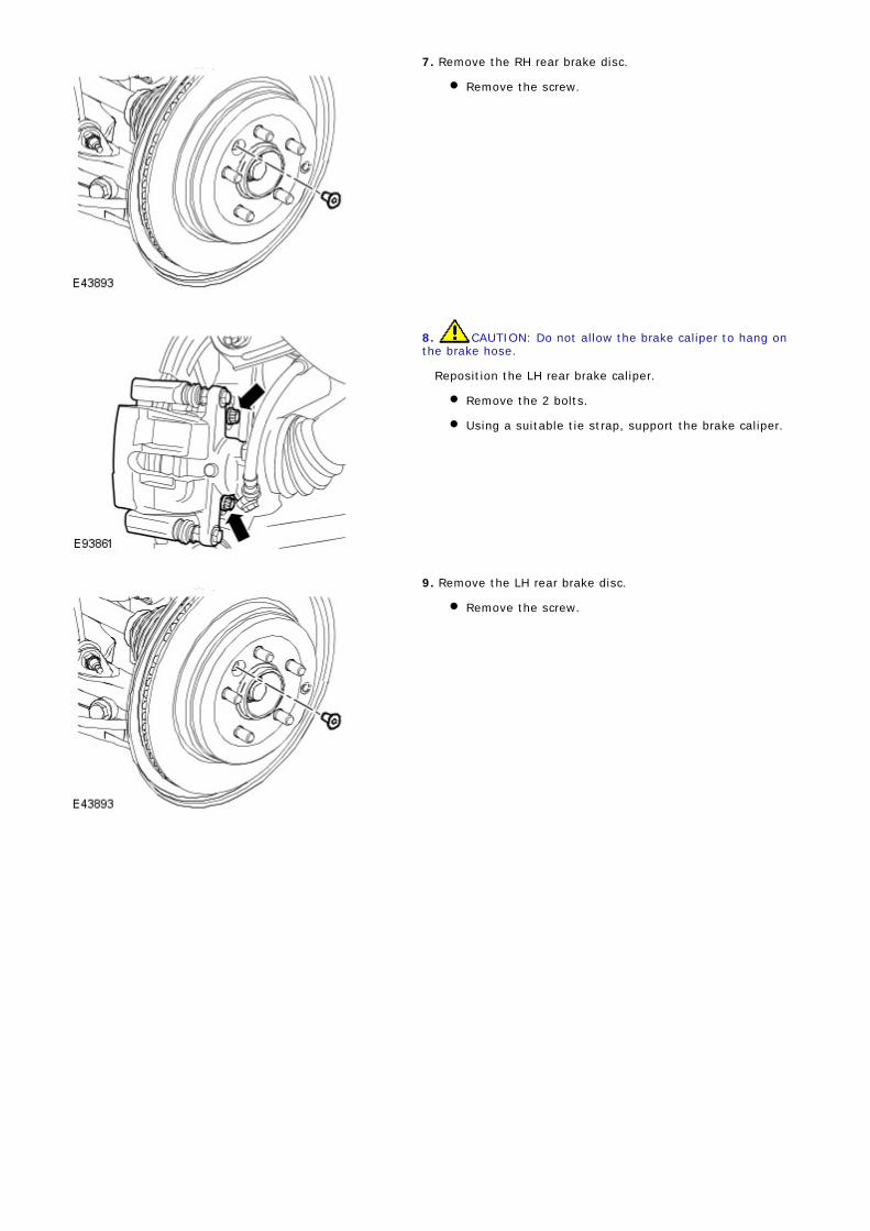
6. CAUTION: Do not allow the brake caliper to hang onthe brake hose.
Reposition the LH rear brake caliper.
Remove the 2 bolts.
Using a suitable tie strap, support the brake caliper.
7. Remove the LH rear brake disc.
Remove the screw.
8. Disconnect parking brake cable from the wheel hub.
Fully loosen the nut.
Release the cable from the lower arm.
Disconnect the inner cable from the brake shoe.
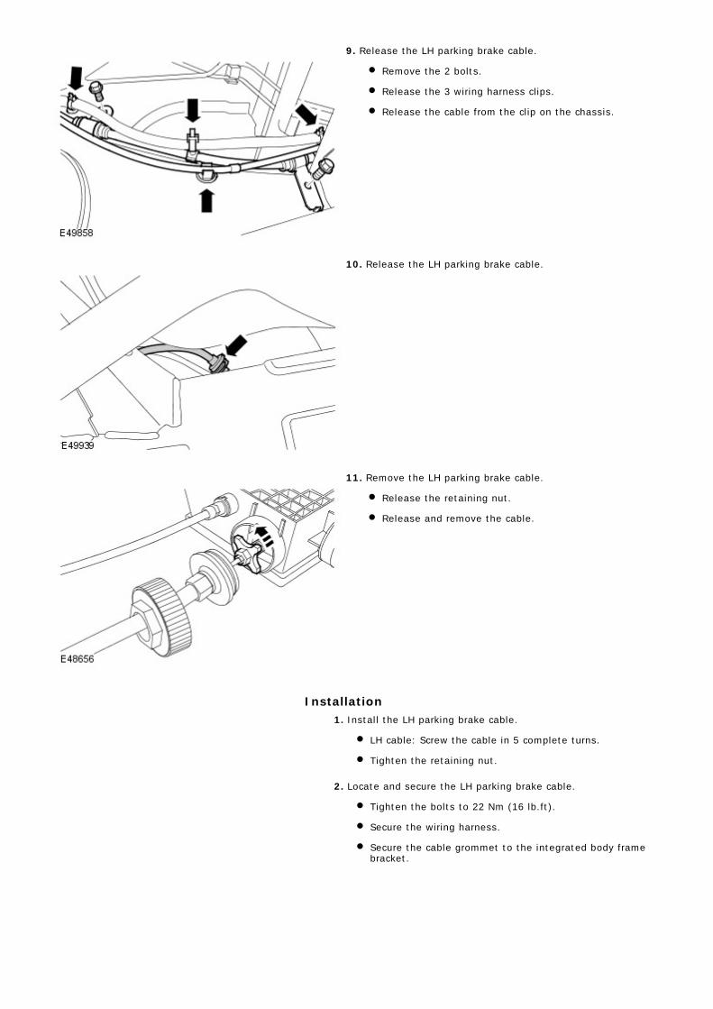
9. Release the LH parking brake cable.
Remove the 2 bolts.
Release the 3 wiring harness clips.
Release the cable from the clip on the chassis.
10. Release the LH parking brake cable.
11. Remove the LH parking brake cable.
Release the retaining nut.
Release and remove the cable.
Installation1. Install the LH parking brake cable.
LH cable: Screw the cable in 5 complete turns.
Tighten the retaining nut.
2. Locate and secure the LH parking brake cable.
Tighten the bolts to 22 Nm (16 lb.ft).
Secure the wiring harness.
Secure the cable grommet to the integrated body framebracket.

3. NOTE: Make sure that the brake cable circlip is positionedas shown.
Connect the parking brake cable to the wheel hub.
Connect the cable to the brake shoe lever.
Locate the cable to the backplate.
Tighten the nut to 8 Nm (6 lb.ft).
4. CAUTION: Make sure that the component is clean, free offoreign material and lubricant.
Install the LH rear brake disc.
Tighten the Torx screw to 35 Nm (26 lb.ft).
5. Secure the LH rear brake caliper.
Remove and discard the tie strap.
Tighten the bolts to 115 Nm (85 lb.ft).
6. NOTE: The adjustment procedure must be carried out in full.
Adjust the parking brake shoes.For additional information, refer to: Parking Brake Shoe andLining Adjustment (206-05 Parking Brake and Actuation,General Procedures).
7. Install the rear wheels and tires.
Tighten the wheel nuts to 140 Nm (103 lb.ft).
8. Install fuse number 8 into the BJB.

Published: 11-May-2011Parking Brake and Actuation - Parking Brake Cable RHRemoval and Installation
Removal
CAUTION: To avoid accidental operation of the parking brake, and possible damage to the parking brake actuator,remove Fusible link 8, located in the engine compartment fuse box before commencing work.
• NOTE: If the parking brake system has completed less than 50,000 cycles it is permissible to replace the parking brakecables. If over 50,000 cycles have been completed, then the cables can only replaced as part of the parking brake actuatorand cable assembly. The parking brake cycle count can be checked using using the Land Rover approved diagnostic system,(ON/OFF = 1 cycle). If a cable breaks or becomes detached whilst the vehicle is being driven, a 'parking brake actuatorunjaming procedure' may be required using the Land Rover approved diagnostic system.
1. Using the Land Rover approved diagnostic system, drive theparking brake to the 'mounting position'.
2. Isolate the parking brake electrical circuit.
Remove fuse number 8 from the BJB.
3. WARNING: Do not work on or under a vehicle supportedonly by a jack. Always support the vehicle on safety stands.
Raise and support the vehicle.4. Remove the wheels and tires.
5. Release the parking brake shoe adjustment.
Loosen the screw.

6. CAUTION: Do not allow the brake caliper to hang onthe brake hose.
Reposition the RH rear brake caliper.
Remove the 2 bolts.
Using a suitable tie strap, support the brake caliper.
7. Remove the RH rear brake disc.
Remove the screw.
8. Disconnect parking brake cable from the wheel hub.
Fully loosen the nut.
Release the cable from the lower arm.
Disconnect the inner cable from the brake shoe.

9. CAUTION: The fuel tank breather line bracket can beeasily damaged when releasing it from the chassis.
Release the fuel tank breather line bracket.
Remove the plastic insert.
10. Release the RH parking brake cable.
Remove the 2 bolts.
Release the parking brake cable from the 2 pipe clips.
Release the cable from the clip on the chassis.
11. Release the RH parking brake cable.

12. CAUTION: Make sure that no dirt or moisture entersthe actuator during cable replacement.
Remove the RH parking brake cable.
Release the retaining nut.
Release the cable retaining clip.
Release and remove the cable.
Installation1. Install the RH parking brake cable.
Install the cable.
Install the cable retaining clip.
Tighten the retaining nut.
2. Secure the fuel tank breather line bracket.
Install the plastic insert.
3. Locate and secure the RH parking brake cable.
Tighten the bolts to 22 Nm (16 lb.ft).
Secure the parking brake cable to the 2 pipe clips.
Secure the cable grommet to the integrated body framebracket.
4. NOTE: Make sure that the brake cable circlip is positionedas shown.
Connect the parking brake cable to the wheel hub.
Connect the cable to the brake shoe lever.
Locate the cable to the backplate.
Tighten the nut to 8 Nm (6 lb.ft).
5. CAUTION: Make sure that the component is clean, free offoreign material and lubricant.
Install the RH rear brake disc.
Tighten the Torx screw to 35 Nm (26 lb.ft).
6. Secure the RH rear brake caliper.
Remove and discard the tie strap.
Tighten the bolts to 115 Nm (85 lb.ft).
7. NOTE: The adjustment procedure must be carried out in full.
Adjust the parking brake shoes.For additional information, refer to: Parking Brake Shoe and

Lining Adjustment (206-05 Parking Brake and Actuation,General Procedures).
8. Install the rear wheels and tires.
Tighten the wheel nuts to 140 Nm (103 lb.ft).
9. Install fuse number 8 into the BJB.

Published: 11-May-2011Parking Brake and Actuation - Parking Brake SwitchRemoval and Installation
Removal
• NOTE: Removal steps in this procedure may contain installation details.
Refer to: Floor Console Upper Section (501-12 Instrument Panel andConsole, Removal and Installation).
1.
2.
3.

4.
5.
Installation
To install, reverse the removal procedure.1.

Published: 11-May-2011Parking Brake and Actuation - Parking Brake ActuatorRemoval and Installation
Removal1. Using the Land Rover approved diagnostic system, drive the
parking brake to the 'mounting position'.2. Isolate the parking brake electrical circuit.
Remove fuse number 8 from the BJB.
3. WARNING: Do not work on or under a vehicle supportedonly by a jack. Always support the vehicle on safety stands.
Raise and support the vehicle.4. Remove the rear wheels and tires.
5. Release the parking brake shoe adjustment.
Remove the plug from the access hole in the brakedisc.
Using a suitable tool, rotate the brake shoe adjuster torelease the adjustment.
6. CAUTION: Do not allow the brake caliper to hang onthe brake hose.
Reposition the RH rear brake caliper.
Remove the 2 bolts.
Using a suitable tie strap, support the brake caliper.
7. Remove the RH rear brake disc.
Remove the screw.
8. CAUTION: Do not allow the brake caliper to hang onthe brake hose.
Reposition the LH rear brake caliper.
Remove the 2 bolts.
Using a suitable tie strap, support the brake caliper.
9. Remove the LH rear brake disc.
Remove the screw.

10. Disconnect both parking brake cables from the wheel hubs.
Fully loosen the nut.
Release the cable from the lower arm.
Disconnect the inner cable from the brake shoe.
11. Release the LH parking brake cable.
Remove the 2 bolts.
Release the 3 wiring harness clips.
Release the cable from the clip on the chassis.
12. Release the LH parking brake cable.

13. CAUTION: The fuel tank breather line bracket can beeasily damaged when releasing it from the chassis.
Release the fuel tank breather line bracket.
Remove the plastic insert.
14. Raise the RH side of the rear stabilizer bar.
Loosen the 2 bolts.
15. Release the RH parking brake cable.
Remove the 2 bolts.
Release the parking brake cable from the 2 pipe clips.
Release the cable from the clip on the chassis.
16. Release the RH parking brake cable.

17. Remove the fuel tank heat shield.
Remove the 3 bolts and 2 nuts.
18. CAUTION: Inspect the parking brake emergencyrelease cable to body seal and replace if damaged.
• NOTE: Note the fitted position of the parking brakeemergency release cable to body seal.
Release the parking brake emergency release cable.
19. CAUTION: Before disconnecting or removing thecomponents, make sure the area around the joint faces andconnections are clean. Plug open connections to preventcontamination.
RH side rear: Disconnect the brake line.
Position an absorbent cloth to collect fluid spillage.
Disconnect the line union.
Remove the clip.
20. NOTE: Note the routing of the parking brake emergencyrelease cable.
Displace the parking brake actuator and cable assembly.
Disconnect the electrical connector.
Remove the 2 nuts.

21. NOTE: Brake cable shown removed for clarity.
Remove the parking brake actuator and cable assembly.
Withdraw from the RH rear wheel arch aperture.
Installation1. NOTE: Note the routing of the parking brake emergencyrelease cable.
Install the parking brake actuator and cable assembly.
Install the 2 nuts.
Connect the electrical connector.
2. NOTE: Remove and discard the blanking caps.
RH side rear: Connect the brake line.
Clean the component mating faces.
Secure the clip.
Tighten the brake line union to 16 Nm (12 lb.ft).
3. CAUTION: Make sure the parking brake emergencyrelease cable to body seal is installed correctly.
Locate and secure the parking brake emergency release cable.4. Install the fuel tank heat shield.
Tighten the bolts to 6 Nm (4 lb.ft).
Tighten the nuts to 3 Nm (2 lb.ft).
5. Secure the fuel tank breather line bracket.
Install the plastic insert.
6. Locate and secure the RH parking brake cable.
Tighten the bolts to 22 Nm (16 lb.ft).
Secure the parking brake cable to the 2 pipe clips.
Secure the cable grommet to the integrated body framebracket.
7. Locate and secure the LH parking brake cable.
Tighten the bolts to 22 Nm (16 lb.ft).
Secure the wiring harness.
Secure the cable grommet to the integrated body framebracket.

8. NOTE: Make sure that the brake cable circlip is positionedas shown.
Connect the parking brake cables to the wheel hubs.
Connect the cable to the brake shoe lever.
Locate the cable to the backplate.
Tighten the nut to 8 Nm (6 lb.ft).
9. CAUTION: Make sure that the component is clean, free offoreign material and lubricant.
Install the LH rear brake disc.
Tighten the Torx screw to 35 Nm (26 lb.ft).
10. Secure the LH rear brake caliper.
Remove and discard the tie strap.
Tighten the bolts to 115 Nm (85 lb.ft).
11. CAUTION: Make sure that the component is clean, freeof foreign material and lubricant.
Install the RH rear brake disc.
Tighten the Torx screw to 35 Nm (26 lb.ft).
12. Secure the RH rear brake caliper.
Remove and discard the tie strap.
Tighten the bolts to 115 Nm (85 lb.ft).
13. Adjust the parking brake shoes.For additional information, refer to: Parking Brake Shoe andLining Adjustment (206-05 Parking Brake and Actuation,General Procedures).
14. Bleed the brake system.For additional information, refer to: Component Bleeding(206-00 Brake System - General Information, GeneralProcedures).
15. Install the wheels and tires.
Tighten the wheel nuts to 140 Nm (103 lb.ft).
16. Install fuse number 8 into the BJB.17. Using the Land Rover approved diagnostic system, calibrate
the parking brake actuator on an even surface.18. Apply and release hand brake to confirm operation.

Published: 11-May-2011Parking Brake and Actuation - Parking Brake ShoesRemoval and Installation
Removal• NOTE: If the parking brake shoes or the brake discs have been removed for access to other components then DO NOTcarry out the bedding in procedure.
1. Using the Land Rover approved diagnostic system, drive theparking brake to the 'mounting position'.
2. Isolate the parking brake electrical circuit.
Remove fuse number 8 from the BJB.
3. WARNING: Do not work on or under a vehicle supportedonly by a jack. Always support the vehicle on safety stands.
Raise and support the vehicle.4. Remove the wheels and tires.5. Release the brake caliper.
Remove the brake caliper anchor bolts.
6. CAUTION: Do not allow the brake caliper to hang on thebrake hose.
Tie the brake caliper aside.

7. Release the park brake shoe adjustment.
Remove the plug from the access hole in the brakedisc.
Using a suitable tool, rotate the brake shoe adjuster torelease the adjustment.
8. Remove the brake disc.
Remove the Torx screw.
9. CAUTIONS:
Make sure that the green bias spring is installed to theright hand parking brake shoes and the red bias spring isinstalled to the left hand parking brake shoes.
Make sure the brake shoe spring is not over stretched.
• NOTE: If equipped.
Remove the bias spring(s).

10. Remove the adjuster and return spring.
Release the parking brake shoe adjuster to theminimum adjustment.
11. Remove the primary brake shoe.
Remove the hold-down spring and retaining pin.
Pivot the shoe to release it from the spreader plate andreturn spring.
12. Remove the spreader plate and spring.

13. Remove the return spring.
14. Remove the secondary brake shoe.
Remove the hold-down spring and retaining pin.
Disconnect the parking brake cable retaining springfrom the brake shoe lever.
Release the parking brake cable.
15. Repeat the above procedure for the other side.
Installation
1. WARNING: Do not use compressed air to clean brakecomponents. Dust from friction materials can be harmful ifinhaled.
Clean the backing plate and apply grease to the brake shoecontacts.
2. Clean the adjuster and set it to its minimum extension.

3. CAUTIONS:
Make sure the brake shoe spring is not over stretched.
Make sure the closed end of the retaining clip isinstalled facing the brake shoe adjuster. Failure to follow thisinstruction may result in damage to the vehicle.
Illustration 'A' is the LH side and 'B' is the RH side.
Install the secondary brake shoe.
Connect the parking brake cable.
Connect the parking brake cable retaining spring to thebrake shoe lever, making sure the spring is not twisted.
Install the hold-down spring and retaining pin.
4. Install the spreader plate and the spring.
Using a tie strap, tie back the spreader plate spring.
5. WARNING: Make sure the return spring and theadjuster spring are correctly installed to the primary shoe.
• CAUTIONS:
Make sure the brake shoe spring is not over stretched.
Make sure the closed end of the retaining clip isinstalled facing the brake shoe adjuster. Failure to follow thisinstruction may result in damage to the vehicle.
Illustration 'A' is the LH side and 'B' is the RH side.
Install the primary brake shoe.
Install the return spring.
Connect the primary brake shoe to the return spring.
Locate the primary brake shoe to the spreader plate.
Install the hold-down spring and retaining pin.
6. CAUTION: Make sure the brake shoe spring is not over

stretched.
Install the brake shoe adjuster and the retaining spring.7. Remove and discard the spreader plate spring tie strap.
8. CAUTIONS:
Make sure that the green bias spring is installed to theright hand parking brake shoes and the red bias spring isinstalled to the left hand parking brake shoes.
Make sure the brake shoe spring is not over stretched.
• NOTE: If equipped.
Install the bias spring(s).
9. Make sure the brake disc and hub mating surfaces are clean.10. Install the brake disc.
Tighten the Torx screw to 35 Nm (26 lb.ft).
11. Install the brake caliper.
Tighten the bolts to 115 Nm (85 lb.ft).
12. Repeat the above procedure for the other side.13. Adjust the parking brake.
For additional information, refer to: Parking Brake Shoe andLining Adjustment (206-05 Parking Brake and Actuation,General Procedures).
14. Install the wheels and tires.
Tighten the wheel nuts to 140 Nm (103 lb.ft).
15. Install fuse number 8 into the BJB.