ekofisk revisited - bearing optimization for improved
TRANSCRIPT
1
Ekofisk Revisited - BearingOptimization for Improved
Rotor StabilityEdgar J. Gunter
Prof. Emeritus Mechanical and Aerospace Engineering, Univ. Of VirginiaFormer Director Rotor-Bearing Dynamics Laboratory
Fellow ASME
Paper Presented by
Erik SwansonPresident/Chief Engineer
Xdot Engineering and Analysis

Outlinen Background and introduction to the Ekofisk field problemn Rotor configurations and shaft modelsn Rotordynamic characteristics of original (Phase I) rotorn These bearings are going to be a disaster....n Let’s try a squeeze film dampern What bearing might have worked?n What about the revised (Phase IV) rotor?n Closing comments
2
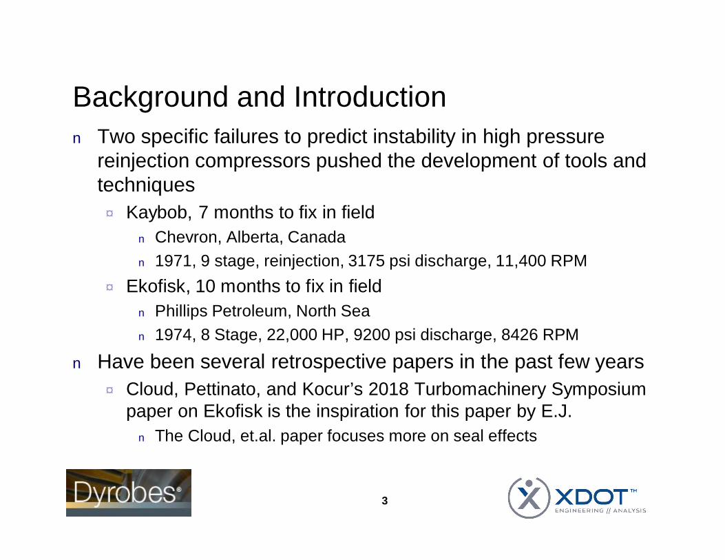
Background and Introductionn Two specific failures to predict instability in high pressure
reinjection compressors pushed the development of tools andtechniques¨ Kaybob, 7 months to fix in field
n Chevron, Alberta, Canadan 1971, 9 stage, reinjection, 3175 psi discharge, 11,400 RPM
¨ Ekofisk, 10 months to fix in fieldn Phillips Petroleum, North Sean 1974, 8 Stage, 22,000 HP, 9200 psi discharge, 8426 RPM
n Have been several retrospective papers in the past few years¨ Cloud, Pettinato, and Kocur’s 2018 Turbomachinery Symposium
paper on Ekofisk is the inspiration for this paper by E.J.n The Cloud, et.al. paper focuses more on seal effects
3

Background and Introductionn Both failures were encountered for high discharge pressure
compressors that were really pushing the state of the art atthe time¨ Machines went unstable due to aerodynamic (Alford) cross-
coupled stiffness forces¨ Were not bearing induced instability
n Lund’s 1964 work had showed that plain journal bearings areunstable
n Both compressors had narrow five-pad, load-on-pad tilting padbearings
n 1970’s state of the art transfer matrix codes could computeundamped critical speeds and unbalance response¨ But they could not adequately analyze rotordynamic stability
4

Background and Introductionn Three other helpful pieces of background information
¨ API specs at the time dictated that compressors should notoperate near critical speedsn Compressor developers were motived to avoid operating near the
second critical speedn This requirement influenced bearing choices
¨ Bently proximity probes were starting to be installed in criticalmachinery such as these compressors, so there is some dataavailable
¨ Both machines looked fine during the mechanical run test at lowpressure/low power
5

Ekofisk Compressor
6
Elliot 25 MBHH(2nd of two compressors in series)
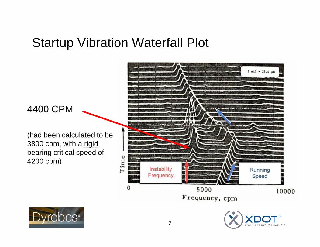
Startup Vibration Waterfall Plot
7
4400 CPM
(had been calculated to be3800 cpm, with a rigidbearing critical speed of4200 cpm)

Phase I Rotor Modeling
n Dyrobes model based on a rotor model presented by Cloudet., al.¨ Includes disk gyroscopic effects (not included in earlier work?)¨ 80.7 inch bearing span¨ 6.7 inch main diameter¨ L/D ratio 12.0
n High!
8
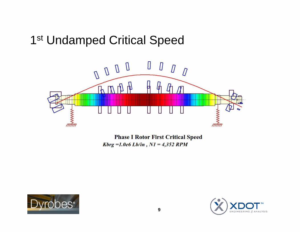
1st Undamped Critical Speed
9

1st Undamped Critical Speed
10
Close Correspondence withmeasured 4400 cpm instability(had been calculated as 3800 cpm!)

1st Undamped Critical Shaft Strain Energy
11

1st Undamped Critical Shaft Strain Energy
12
Way too high
E.J.’s rule of thumb, bearingsneed to each have at least 20% oftotal stain energy for mode ofinterest to have much effect
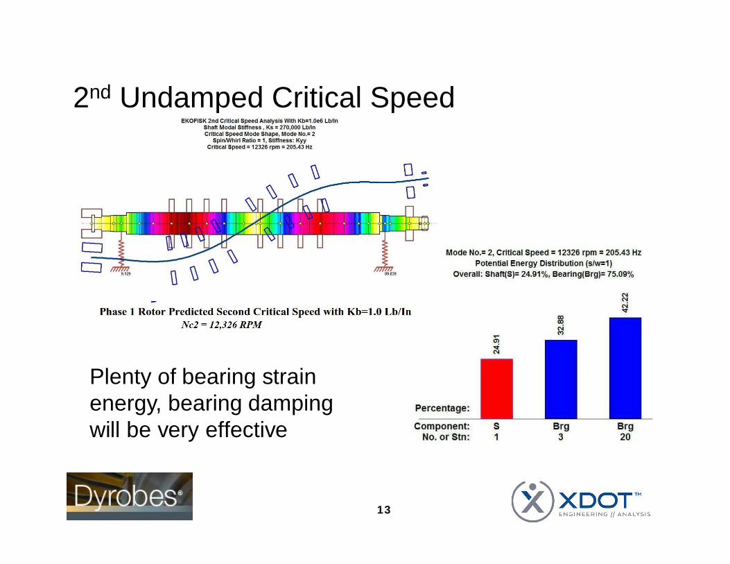
2nd Undamped Critical Speed
13
Plenty of bearing strainenergy, bearing dampingwill be very effective
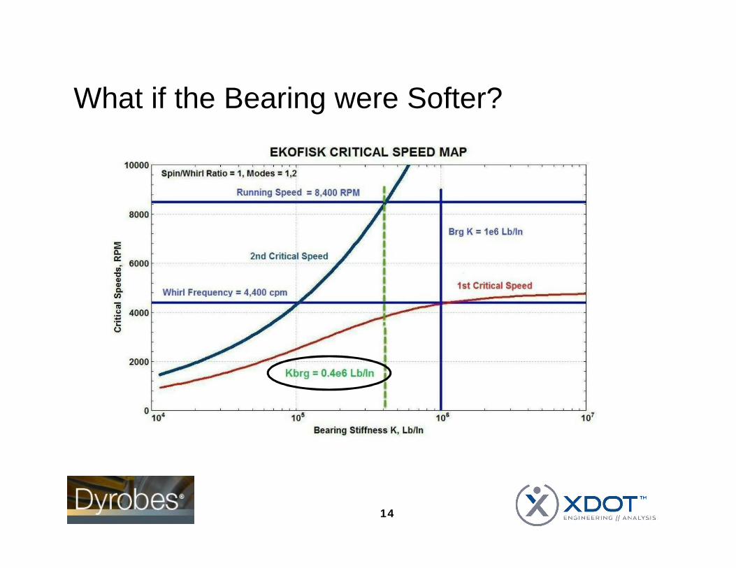
What if the Bearing were Softer?
14

What if the Bearing were Softer?
15

Bearing Analysis Using Dyrobesn Phase I bearings are narrow (L/D = 0.284), 5 pad, load on
pivot tilting pad bearings¨ 0.54 offset¨ 0.29 – 0.53 preload (nominal preload = 0.3 used for this paper)¨ Predicted Kyy stiffness: 1.292e6 lbf/in
16

Some Observationsn For a simple flexible rotor, it can be shown that there is an
optimum shaft to bearing stiffness ratio
Kyy_ratio = ଶ௬௬௦
, Kyy_ratio_optimal = 1
n Using the shaft modal stiffness of 2.7e4 lbf/in
Kyy_ratio_original = ଶ௬௬௦
= ଶ(ଽ.ହହ)ଶ.ସ
= 7.03
Kyy_ratio_Dyrobes= ଶ௬௬௦
= ଶ(ଵ.ଶଽ)ଶ.ସ
= 9.56
17
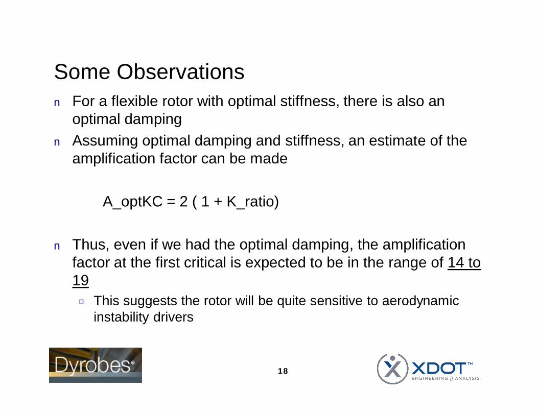
Some Observationsn For a flexible rotor with optimal stiffness, there is also an
optimal dampingn Assuming optimal damping and stiffness, an estimate of the
amplification factor can be made
A_optKC = 2 ( 1 + K_ratio)
n Thus, even if we had the optimal damping, the amplificationfactor at the first critical is expected to be in the range of 14 to19¨ This suggests the rotor will be quite sensitive to aerodynamic
instability drivers
18
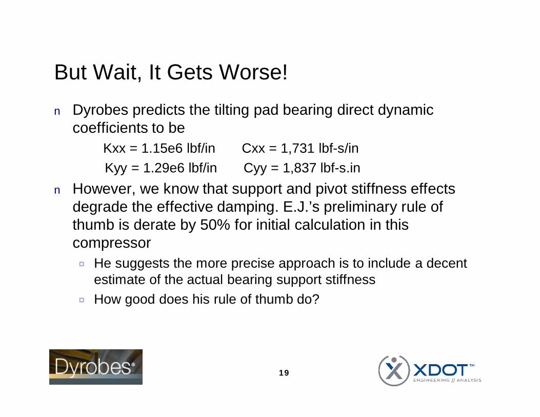
But Wait, It Gets Worse!n Dyrobes predicts the tilting pad bearing direct dynamic
coefficients to beKxx = 1.15e6 lbf/in Cxx = 1,731 lbf-s/inKyy = 1.29e6 lbf/in Cyy = 1,837 lbf-s.in
n However, we know that support and pivot stiffness effectsdegrade the effective damping. E.J.’s preliminary rule ofthumb is derate by 50% for initial calculation in thiscompressor¨ He suggests the more precise approach is to include a decent
estimate of the actual bearing support stiffness¨ How good does his rule of thumb do?
19

But Wait, It Gets Worse!
20
No adjustmentN = 4563 cpmLog. Dec. = 0.25
First mode at 8500 rpm
50% DerateN = 4486 cpmLog. Dec. = 0.15
Measured Instability 4400 cpm

Rotor Stabilityn An approximate rotor stability limit for a symmetric, flexible
rotor is given by (I think this assumes optimum damping)
n This is well below the desired 100,000 to 200,000 lbf/in¨ Cloud et al. give the API Level 1 cross coupling as 207,000 lbf/in
21

Rotor Stabilityn This compressor will almost certainly be unstable!
¨ Even without consideration of oil ring seal effectsn Fundamental issue is that the narrow five pad LOP bearings
are too stiff¨ They were probably selected to push the second critical speed
up to well above the operating speed range¨ Causes the rotor to be very sensitive to self-excited whirling
forces¨ This characteristic is also sometimes seen in more modern
compressors if tilting pad bearings with large offset are usedn A machine with stiff bearings relative to the shaft stiffness is almost
always undesirable unless the machine is running below the firstcritical speed
22

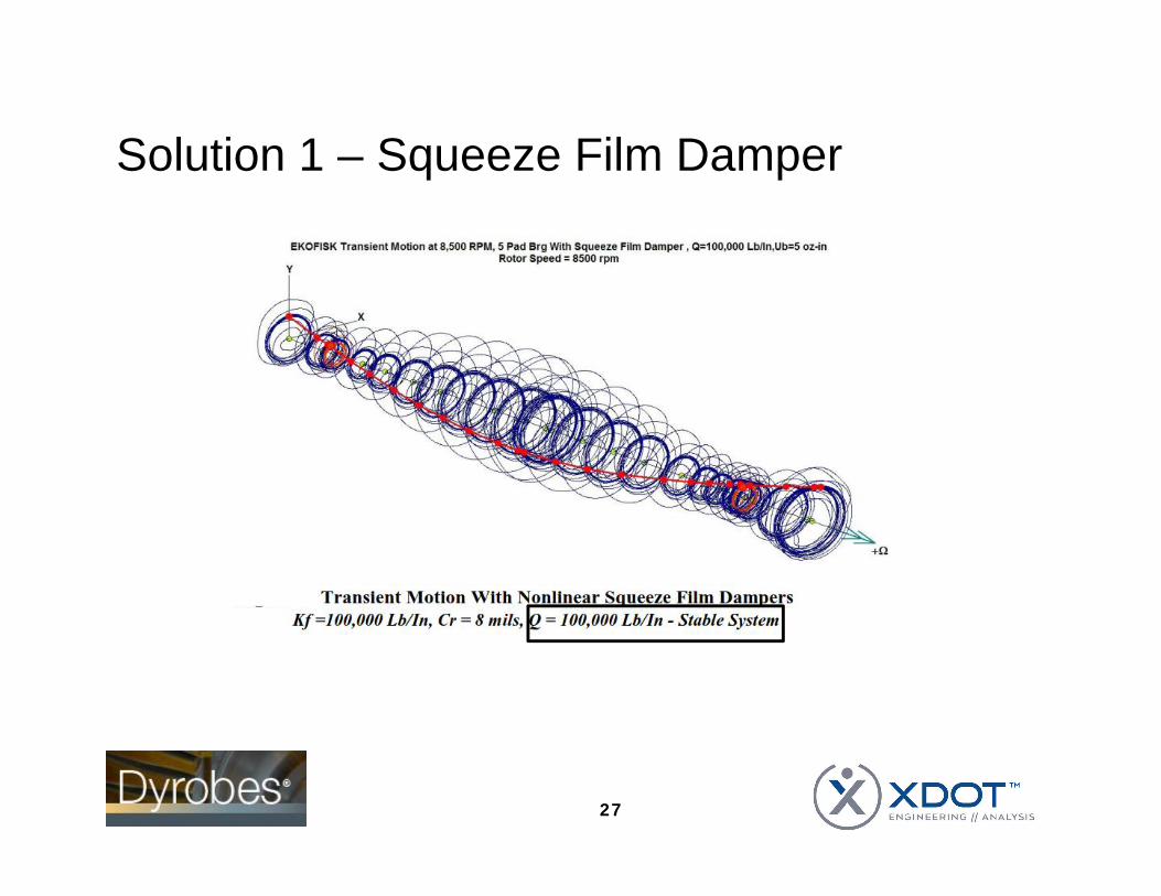
Time Transient Responsen Modern rotordynamic tools such as Dyrobes can perform a
time transient response with the full bearing calculationperformed at every time step¨ These tools were not available in the 1970’s¨ Will show the instability
23
Solution 1 – Squeeze Film Dampern Paper has considerable detailn Can use optimal support stiffness (half shaft modal stiffness)
for an initial estimate of target damper stiffness¨ Too high damper stiffness reduces the amount of acceptable
aerodynamic cross-couplingn Can run parametric study to determine the range of damping
that works and the maximum amount of aerodynamic cross-coupling that can be applied and the system remain stable¨ Not enough damping -> the amount of cross-coupled stiffness
that can be applied drops¨ Too much damping -> damper “lock-up” and is not effective
24

Solution 1 – Squeeze Film Damper
25
All are much higherthan the original limit ofless than 20,000 lbf
Solution 1 – Squeeze Film Dampern Sizing and Dimensions
¨ Dyrobes has a calculation tool that can be usedn Central circumferential groove
¨ Be very careful about central grooves, some equations assumethe damper has a central circumferential groove. If it is modeled,but not present in the hardware, there is a high risk of lockupn E.J. believes this was a problem with one of the Kaybob fixes
n O-Rings¨ O-ring end seal stiffnesses must be included in parallel with the
damper coefficients if o-rings are used to seal the ends of thedamper
¨ Be aware of the potential for shaft weight to crush the o-ringn Centered dampers are preferred
26
Solution 1 – Squeeze Film Damper
27

Solution 2 – Softer Bearing, 4 Pad LBP
28
Longer bearing(was 1.5 inch)

Solution 2 – Softer Bearing, 4 Pad LBP
29
Solution 2 – Softer Bearing, 4 Pad LBPn But wait ... what about the second critical speed?n The softer bearing has enough damping that the second
mode is an overdamped, rigid body conical mode¨ Does not get excited
n Next critical speed is well above operating speedn The early 1970’s tools would have had a hard time verifying
that the second critical speed was not a concern
30

Solution 3 – Shorter, Larger Diameter Rotor
31
L/D = 8.4
L/D = 12

Solution 3 – Clock Bearing to be LBP
32
Also went to center (50%) pivot andincreased clearance which reducespreload
Unloaded toppad – flutter risk
Arguably, this is actually a 4pad LBP bearing, since thetop pad is not doing much

Solution 3 – Clock Bearing to be LBP
33
Stable with100,000 lbf/incross-coupling
Discussion and Conclusionsn Design practices and codes of the time drove the Ekofisk
design towards a long (flexible) shaft and narrow, very stiffbearings
n This is generally not a desirable combination¨ Modal strain energy is all in the shaft¨ Bearing damping is not vey effective in reducing amplification
factors or providing rotordynamic stabilityn The Dyrobes re-analysis does a very good job matching the
observed instability frequency without considering oil sealeffects¨ Original analysis did not match very well
34

Discussion and Conclusionsn Solutions
¨ Major rotor redesignn Implemented in 1974n Shorter, larger diameter rotor (stiffer)n Switched to load between pivot bearings with more clearance
(softer)¨ Squeeze film damper
n Carefully designed damper probably would have worked withoriginal rotor
¨ 4 pad load between pads bearingn Carefully designed 4 pad bearings probably would have worked with
original rotor
35

Thank-You forListening!
36