steel-to-timber dowel joints - diva portal205087/fulltext01.pdf · thesis for the degree of...
TRANSCRIPT

THESIS FOR THE DEGREE OF LICENCIATE OF ENGINEERING
STEEL-TO-TIMBER DOWEL JOINTS
-INFLUENCE OF MOISTURE INDUCED STRESSES
JOHAN SJÖDIN
School of Technology and Design Växjö University
Växjö, Sweden 2006

2

3
ACKNOWLEDGEMENTS
This work has been financially supported from the Wood Science Program at Växjö University (WDAT - Wood Design and Technology), the Development Fund of the Swedish Construction Industry (SBUF) and Skanska AB. The work is also part of a Swedish-Finish project financed by TEKES and VINNOVA. Special thanks to GOM GmbH in Germany and Cascade Computing AB in Sweden for use of their contact-free measurement equipment, and to Moelven Töreboda Limträ AB for providing the glulam beams used in the experimental work.
First of all, I would like to thank my supervisors, Prof. Carl Johan Johansson and Prof. Hans Petersson, for all their support and assistance during this work. I also want to express my deepest gratitude to Mr. Arne Emilsson at Limträteknik AB and Mr. Bertil Enquist. They have both contributed with their opinions, encouragement, assistance and skills before, during and after the experimental work, which represents a very important part of the thesis. Special thanks also to Dr. Erik Serrano for co-authoring two of the papers and for his valuable opinions in connection with it.
I would like to further express my deepest gratitude to Mr. Sigurd Karlsson and Dr. Joakim Jeppsson, both at Skanska Teknik, for their support and guidance during my work. Thanks also to my colleagues at Skanska Teknik in Växjö and at Växjö University.
Finally, I wish to express my deepest gratitude to my family, in particular to my mother (Elma Marjatta Sjödin 1938-2005) and my father, to whom this thesis is dedicated.
Växjö, July 2006
Johan Sjödin

4

5
ABSTRACT
Joints are critical parts of timber structures, transmitting static and dynamic forces between structural members. The ultimate behavior of a loaded building depends strongly on the structural configuration and the capacity of the joints. The collapse of a whole building or less extensive accidents that may occur is usually starting as a local failure inside or in the vicinity of a joint. Such serious failures have recently occurred in our Nordic countries. Especially the collapse of two large glued laminated timber structures clearly indicates the need of an improved joint design. The trend toward larger and more complex structures even further increases the importance of a safer design of the joints.
An aim of this partly experimental and partly numerically based thesis has been to investigate if steel-to-timber dowel joints are affected by moisture-induced stresses. The experimental results showed that the load-bearing capacity of the joints is reduced by such a moisture influence. Most of the decrease in load-bearing capacity observed was found in joints initially exposed to restrained shrinkage deformations caused by the presence of dowel fasteners in the joint area. The load-bearing capacity was, however, also found to decrease in joints exposed to an initial decrease in moisture without any fasteners present in the specimens during storage before loading. An explanation of this unexpected behavior is that moisture gradients cause tensile stresses. It is shown by numerical simulations that the moisture-induced stresses are so large that they may have a considerable influence on the joint behavior.
Use of contact-free measurement methods, used in some of the experimental tests, was in many ways found to be superior to traditional measurement techniques, but was also found to be a valuable complement to the numerical analysis performed. From numerical results obtained in combination with results from contact-free measurements several observations of considerable interest were made. For dowel-type joints loaded in tension parallel to the grain a strongly non-uniform strain distribution was found in the joint area. It was further observed that the shear and tensile strains were concentrated close to the fasteners in the joint area. These concentrations will influence the failure mode of the joint. A general observation was that the larger sized joints failed in a brittle manner.
Keywords: constraint stresses, contact-free measurement, dowel-type joints, humidity variations, moisture-induced deformations, timber structures

6

7
APPENDED PAPERS
Paper A:
Influence of moisture-induced stresses in steel-to-timber dowel joints
Johan Sjödin, Carl Johan Johansson and Hans Petersson
Presented at the World Conference on Timber Engineering, June 14-17, Lahti, Finland, 2004
Paper B:
Influence of moisture induced stresses in multiple steel-to-timber dowel joints
Johan Sjödin and Carl Johan Johansson
Accepted for publication in Holz als Roh- und Werkstoff, 2006.
Paper C:
A numerical study of the effects of stresses induced by moisture gradients in steel-to-timber dowel joints
Johan Sjödin and Erik Serrano
Accepted for publication in Holzforschung, 2006.
Paper D:
Contact-free measurements and numerical analyses of the strain distribution in the joint area of steel-to-timber dowel joints
Johan Sjödin, Erik Serrano and Bertil Enquist
Accepted for publication in Holz als Roh- und Werkstoff, 2006.

8

9
TABLE OF CONTENTS
ACKNOWLEDGEMENTS............................................................................................. 3
ABSTRACT .................................................................................................................... 5
APPENDED PAPERS..................................................................................................... 7
1 INTRODUCTION................................................................................................. 11
1.1 Large-scale timber structures................................................................................ 11
1.2 Dowel-type joints.................................................................................................. 11
1.3 Background........................................................................................................... 12
1.4 Aim ....................................................................................................................... 14
1.5 Limitations............................................................................................................ 14
1.6 Outline of the thesis .............................................................................................. 14
2 STEEL-TO-TIMBER DOWEL JOINTS LOADED IN TENSION
PARALLEL TO THE GRAIN .............................................................................. 17
2.1 General design ...................................................................................................... 17
2.2 Effects of different configurations ........................................................................ 19
3 BEHAVIOR OF TIMBER EXPOSED TO VARIATIONS IN HUMIDITY........ 21
3.1 General.................................................................................................................. 21
3.2 Relationship between timber strength and moisture ............................................. 23
3.3 Shrinkage and swelling in timber ......................................................................... 23
3.4 Moisture-induced stresses..................................................................................... 24
4 NUMERICAL SIMULATIONS OF THE MOISTURE DISTRIBUTION IN
A GLULAM BEAM DURING REALISTIC CONDITIONS............................... 27
4.1 Presentation of the glulam beam studied and the humidity conditions
simulated ............................................................................................................... 27
4.2 Numerical analyses ............................................................................................... 28
4.3 Limitations in the numerical simulations.............................................................. 29

10
4.4 Numerical results .................................................................................................. 30
4.5 Discussion............................................................................................................. 32
5 EFFECTS OF RESTRAINED SHRINKAGE DEFORMATIONS IN THE
JOINT AREA OF DOWEL-TYPE JOINTS ......................................................... 33
5.1 Introduction .......................................................................................................... 33
5.2 Experimental set-up .............................................................................................. 34
5.3 Experimental results ............................................................................................. 36
5.4 Numerical simulations of the stress distribution in the joint area ......................... 39
5.5 Results of numerical simulations .......................................................................... 41
6 CONCLUDING REMARKS ................................................................................ 45
6.1 Thesis summary and conclusions.......................................................................... 45
6.2 Further work ......................................................................................................... 46
7 REFERENCES...................................................................................................... 47
APPENDED PAPERS A-D

11
1 INTRODUCTION
1.1 Large-scale timber structures
The thesis concerns joints in large-scale timber structures. Sports arenas, exhibition halls and commercial centers are examples of such buildings. Figure 1 shows an exhibition hall and a sports arena that exemplifies this. There are several advantages of buildings of this kind: they are attractive in appearance, the fire protection qualities are high if the timber is used properly, the timber is environmentally friendly and it has a low weight in relation to strength, which simplifies the foundation construction and facilitates the elements to be fabricated and then transported to the construction site.
Figure 1 At the left an exhibition hall in Gothenburg, Sweden, with glulam trusses and at
the right a sports arena in Lillehammer, Norway, with glulam-trussed arches. The pictures are reproduced by the permission of Svenskt Limträ AB (www.svensktlimtra.se).
1.2 Dowel-type joints
Joints, which are the subject of this thesis, are important elements in large-scale timber structures. The design of a structure is frequently limited by the design and the capacity of the joints. The trend toward building larger and more complex structures increases the importance of joints being secure in their design.
Dowel-type joints are one of the most common types for structures of this sort. The fasteners comprise anything from nails, screws, staples, drift pins, threaded rods to bolts (Blass, 2003). Mechanical joints of this kind allow a certain initial displacement between the parts that are connected, one that needs to be taken into account (Racher, 1995). The

12
size of this displacement depends partly on the initial gaps that exist between the fastener and the wood in the joint area. One reason for mechanical joints being used is that they are expected to generate ductile failure, which is an important factor for increasing the safety of timber structures.
In the dowel-type joints studied here, the elements involved are connected by steel plates and steel dowels, see Figure 2. Such steel-to-timber dowel joints are commonly used for glulam trusses of varying span. The buildings shown in Figure 1 are examples of structures in which this type of joints are employed.
Figure 2 A steel-to-timber dowel joint.
1.3 Background
Moisture variations in timber structures during construction and during service life can be considerable. Weather exposure during construction, the type of structure involved and the climatic conditions in the finished building can strongly affect the moisture conditions in a structure (Nevander and Elmarsson, 2001). Matters of this kind should be taken account of in designing timber structures, since timber has the capability of absorbing and desorbing moisture from the surroundings, which can generate problems of different kinds. Damage by microorganisms, unexpected movements of timber elements and moisture induced cracks, for example, are problems that are frequently reported.
The thesis concerns variations in humidity that generate moisture-induced stresses in timber elements. Moisture gradients and restraints on swelling and shrinkage deformations can induce such stresses. This can help explain cracks being so common in timber and glulam structures. It has also been shown that even without any cracks being formed, the capacity of notched beams, prismatic glulam specimens loaded perpendicular to the grain and of curved beams can be affected by moisture-induced stresses (Gustafsson et al. 1998; Jönsson and Thelandersson 2003; Aicher et al. 1998). This can

13
be explained on the basis of the stress distribution that moisture gradients produce interacting with the stress distribution generated by mechanical loads.
Reasons for dowel-type joints being considered sensitive to changes in humidity are the following:
difficulties in covering the large timber elements during construction, resulting in exposure to considerable variations in humidity,
joints of this type facilitate a high degree of moisture transport due to the end grain often being exposed and the existence of slots for the steel plates (Figure 3),
internal stresses induced by moisture gradients and by mechanical loads interact in similar manners as described above for notched beams, and
the presence of steel dowels and steel plates in the joint area causing constraint stresses according to Figure 4.
1
2
3MOISTURE TRANPORT WAY
1. End grain (parallel tofthe grain)2. Perpendicular to thefgrain (all four sides) 3. Inside the cut
WAYS OF MOISTURE TRANSPORT
1. End grain (parallel to the grain)
2. Perpendicular to the grain (all four sides)
3. Inside the saw cuts
Figure 3 Ways of moisture transport in a steel-to-timber dowel joint.

14
A
A
Shrinkage due to drying
L L - L
Stage 1, before changes in humidity
Constraint stresses in
the joint area
Stage 2, after changes in humidity
A-A A-A
Figure 4 Constraint stresses caused by the moisture-induced deformations being restrained by the dowels, which are fixed in position by the steel plate.
1.4 Aim
The major aim of the thesis is to investigate how and to what extent moisture-induced stresses affects the load-bearing capacity of multiple steel-to-timber dowel joints when these are loaded in tension parallel to the grain. The moisture-induced stresses are seen as being induced by shrinkage deformations being restrained perpendicular to the grain by the dowels according to Figure 4. Stresses induced by moisture gradients are also to be considered. How the configuration of the joints affects the sensitivity to moisture-induced stresses is also to be studied.
Contact-free deformation measurements are carried out in some of the experimental tests. The aim of this is to increase the understanding of dowel-type joints exposed either to moisture changes or to a mechanical load. The aim is also to illustrate the advantages and the possibilities of such measurements, which does not appear to have been used previously for dowel-type joints.
1.5 Limitations
The limitations of the thesis include the fact that only multiple dowel-type joints containing steel plates and steel dowels have been studied and that the joints were only loaded in tension parallel to the grain. Although the stiffness of such joints is important, little attention is directed at this in the study, the load-bearing capacity of the joints being of major interest. The effects of cyclic changes in climate conditions and of long-term loadings are also not considered in the study.
1.6 Outline of the thesis
This section gives a brief outline of the content in the thesis, which consists of an extended summary and the papers that are appended.
Chapter 1 is an introduction to the thesis as a whole.

15
Chapter 2 provides a review of the literature on steel-to-timber dowel joints loaded in tension parallel to the grain.
Chapter 3 provides a review of the literature on the mechanical effects of timber being exposed to variations in humidity.
In Chapter 4, the effect of humidity changes in a common glulam beam is numerically simulated. The idea is to provide a qualitative impression of how the moisture contents in a glulam beam varies and how moisture gradients are generated in the cross-section of the beam when exposed to realistic conditions.
In Chapter 5, numerical simulations concerning the effects of restrained shrinkage deformations in steel-to-timber dowel joints are presented and compared with experimental results obtained in some of the appended papers.
Thesis summary and main conclusions together with proposals for further investigations are taken up in Chapter 6.
Appended papers are:
Paper A: Influence of moisture-induced stresses in steel-to-timber dowel joints. This conference paper presents experimental results of the effect of moisture-induced stresses for small-scale joints loaded parallel to the grain.
Paper B: Influence of moisture induced stresses in multiple steel-to-timber dowel joints.This paper is a follow-up of Paper A, large- rather than small-scale joints being investigated.
Paper C: A numerical study of the effects of stresses induced by moisture gradients in steel-to-timber dowel joints. This paper is a numerical study in which the effects of moisture gradients for steel-to-timber dowel joints are studied.
Paper D: Contact-free measurements and numerical analyses of the strain distribution in the joint area of steel-to-timber dowel joints. This paper presents experimental and numerical results concerning strain distributions in the joint area of multiple dowel-type joints loaded in tension.

16

17
2 STEEL-TO-TIMBER DOWEL JOINTS LOADED IN TENSION PARALLEL TO THE GRAIN
2.1 General design
Design rules for dowel-type joints are generally based on Johansen´s yielding theory (Johansen, 1949), in which perfect plasticity of both the dowels and the timber is assumed. In Eurocode 5 (2004) this is taken account of by considering different failure modes. The possible failure modes for a dowel-type joint in which a single steel plate is inserted in a slot in the wood are presented in Figure 5, together with the equations associated with them, where t stands for the thickness of the timber, d for the diameter of the dowels, fh for the embedment capacity of the timber and My for the yield moment of the dowels. As can be seen in figure 5, the embedment strength of the timber has to some extent been reached for all three failure modes. For failure modes 2 and 3 also the bending capacity of the dowels being reached, leading to one and three plastic hinges, respectively, being created.
Different restrictions have been adopted in Eurocode 5 (2004) in the effort to adapt Johansen´s yielding theory to real situations. The reason for this is that, normally, the load-bearing capacity of a multiple dowel-type joint, divided by the number of dowels is not equal to the load-bearing capacity of a single dowel. This is due to the load distribution among the dowels being uneven and that joints of this type tend to show brittle failure modes, in accordance with Figure 6, before the load-bearing capacity of individual dowels is reached. This has been studied in various investigations, in particular with multiple dowel joints involving a single row of dowels loaded in tension parallel to the grain, see e.g. Cramer (1968), Lantos (1969), Isyumov (1967), Wilkinson (1986) and Jorissen (1998). The findings of these and other studies have led to the placement of the dowels being restricted in the manner shown in Figure 7 and to the total number of dowels in the load direction being reduced to an effective number of dowels (Eurocode 5 2004).

18
IIIModedfM
IIModetdf
Mdtf
IModedtf
F
hy
h
yh
h
y
3.2
14
2min 2
Figure 5 Possible failure modes for a dowel joint in which a steel plate is inserted in a slot in the wood (Pedersen et al. 1999). The equations presented are similar to those
included in Eurocode 5 (2004).
Figure 6 Expected final failure modes for multiple dowel joints loaded in tension parallel to the grain.

19
a 3t a 1
a 2
t = thickness of side members
d = diameter of the dowels
a 4c
Minimum spacingor distance
a1 = 5da2 = 3da3t = 7da4c = 3d
Figure 7 Dowel placements according to Eurocode 5 (2004) for a dowel-type joint loaded in tension parallel to the grain.
2.2 Effects of different configurations
How the configuration setups, material properties, numbers of dowels, etc. influence the behavior of dowel-type joints has been studied in a number of investigations by use of both theoretical and experimental methods. For joints with a single row of dowels placed in the load direction parallel to the grain, extensive work has been carried out, as already indicated. Jorissen (1998), for example, concluded that the number of fasteners, the spacing between them in the load direction (a1 in Figure 7) and the slenderness ratio are the most important parameters for dowel-type joints loaded in tension parallel to the grain. Jorissen showed both theoretically and experimentally that increasing the spacing between the dowels in the load direction led to the load-bearing capacity being increased and brittle tendencies being avoided to a greater extent.
Extensive experimental work on dowel-type joints having several dowel rows perpendicular to the grain has been carried out in Canada (Quenneville, 1997; Quenneville and Mohammad, 2000). It was found, for example, that reducing the distance between the end grain and the first dowel column (a3t in Figure 7) leads to the load-bearing capacity being reduced and the row-shear-out failure mode (Figure 6) being more prominent. It was also concluded that the thickness of the side members of the timber (t in Figure 5 and 7) affected the joints, not only their load-bearing capacity, as expected, but also the failure mode. Increasing the thickness generated block-shear failure, whereas the row-shear-out failure mode was more prominent when the thickness was less. An interesting observation made, also verified in paper B of the present thesis, was that the spacing between the dowel rows perpendicular to the grain (a2 in Figure 7) affected both the load-bearing capacity and the failure mode. When the distance between the dowel rows was increased, the load-bearing capacity likewise increased and the failure mode changed from the block-shear failure to the row-shear-out failure mode.

20

21
3 BEHAVIOR OF TIMBER EXPOSED TO VARIATIONS IN HUMIDITY
3.1 General
3.1.1 Moisture in timber
Moisture in timber can be found as free water in the cell cavities and as bound water within the cell walls (Siau 1995). When only bound water is present, the timber material exchanges moisture with its surroundings continually (Dinwoodie 2000; Siau 1995; Skaar 1988). A change in the air humidity thus implies that the wood will either absorb or desorb moisture to the surroundings. This relationship between the air humidity and the moisture content of the timber is expressed as isothermal sorption, which is higly dependent upon both the species and the temperature. The relationship also depends upon whether the timber is absorbing moisture from the surroundings or is desorbing it, as expressed by the hysteresis effect.
In the following, the relative humidity (RH), expressed in percent, will be referred to instead of water pressure. RH is defined as the ratio of the partial vapour pressure in the air to the saturated vapour pressure.
The moisture content of timber is further defined in the thesis as either
int
od
od
mmmMC ·100 [%] (1)
or
100MCw 0 [kg/m3] (2)
where mint is the initial weight of a timber sample, mod is the weight of it after its being oven-dried at 105oC and 0 is the density of the wood at zero moisture content.
Under extremely dry conditions the MC of timber is close to zero. When the humidity increases and approaches 100%, the MC of timber is about 28 %. This level is expressed as the fibre-saturation point. In theory, this is the point at which there is no free water in the cell cavities, whereas the amount of bound water held in the walls is at a maximum (Dinwoodie 2000). According to Dinwoodie (2000), in practice a small amount of free water may still exist, even at the fibre-saturation point. The fiber-saturation point is very interesting from a physical point of view. Changes in MC below this point affect the
22
properties of the timber, causing moisture-induced deformations, a matter discussed further below.
3.1.2 Moisture transport in timber
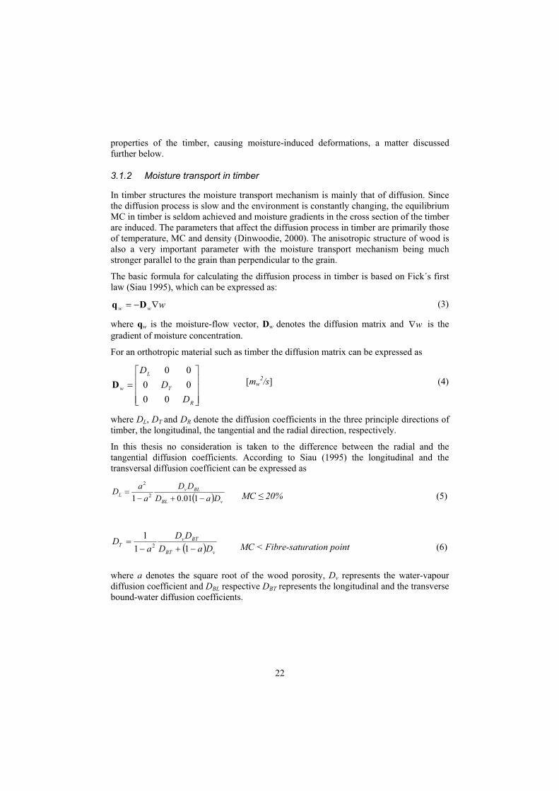
In timber structures the moisture transport mechanism is mainly that of diffusion. Since the diffusion process is slow and the environment is constantly changing, the equilibrium MC in timber is seldom achieved and moisture gradients in the cross section of the timber are induced. The parameters that affect the diffusion process in timber are primarily those of temperature, MC and density (Dinwoodie, 2000). The anisotropic structure of wood is also a very important parameter with the moisture transport mechanism being much stronger parallel to the grain than perpendicular to the grain.
The basic formula for calculating the diffusion process in timber is based on Fick´s first law (Siau 1995), which can be expressed as:
www Dq (3)
where qw is the moisture-flow vector, Dw denotes the diffusion matrix and w is the gradient of moisture concentration.
For an orthotropic material such as timber the diffusion matrix can be expressed as
R
T
L
w
DD
D
000000
D [mw2/s] (4)
where DL, DT and DR denote the diffusion coefficients in the three principle directions of timber, the longitudinal, the tangential and the radial direction, respectively.
In this thesis no consideration is taken to the difference between the radial and the tangential diffusion coefficients. According to Siau (1995) the longitudinal and the transversal diffusion coefficient can be expressed as
101.01 2
2
DaDDD
aaD
vBL
BLvL MC 20% (5)
DaDDD
aD
vBT
BTvT 11
12 MC < Fibre-saturation point (6)
where a denotes the square root of the wood porosity, Dv represents the water-vapour diffusion coefficient and DBL respective DBT represents the longitudinal and the transverse bound-water diffusion coefficients.

23
3.2 Relationship between timber strength and moisture
It is well known that both the strength and the stiffness of timber depend on the MC of the timber. A decrease of the MC usually corresponds to an increase of the strength of the timber and vice versa. According to Dinwoodie (2000), this relationship may change if the timber contains defects, such as knots. High-strength timber is also more strongly affected by changes in MC than low-strength material is (Dinwoodie 2000). According to Ranta-Maunus (2003), there is a limit to MC, below which the strength of the timber no longer increases when drying occurs. A rule of thumb is that the strength of timber has its maximum at around 10 % MC (Ranta-Maunus 2003).
Tendencies similar to those for clear wood have also been noted in small-scale timber joints. For example, Rammer and Winistorfer (2001) and Rammer (2001) showed in experimental tests that the dowel-bearing capacity, see the load-setup in Figure 8, and the nail-bearing capacity of clear southern pine increased when a decrease in MC occurred
LOAD
Figure 8 Specimen used for studying the effects of the moisture content on dowel-bearing strength (Rammer and Winistorfer 1999).
3.3 Shrinkage and swelling in timber
Shrinkage and swelling deformations in timber occur when the MC of the timber changes. The change in deformation that occurs can be expressed as
l = MC · · l (7)
where l is the change in length, MC is the change in moisture content expressed as a percentage, is the shrinkage and swelling coefficient and l is the initial length of the timber specimen.

24
Typical values for the shrinkage and swelling coefficients ( ) of Norway spruce timber as given in timber handbooks (Carling, 2001, for example) are 0.0001 in the longitudinal direction and 0.002 in the cross-grain direction. Longitudinal shrinkage and swelling deformations in normal wood are usually not considered for practical reasons because of their values being so small. In larger pieces of timber, however, longitudinal deformations can be a problem (Hoffmeyer 1995). For example, if the upper and the lower part of a glulam beam differ in MC, substantial deflection of the beam may occur.
The normal shrinkage and swelling behavior of timber can differ, for example, if juvenile wood or compression wood is involved. According to experimental tests that Bengtsson (1999) has performed, the shrinkage and swelling coefficients ( ) for Norway spruce vary between 0.00001 and 0.00035 in the longitudinal direction, between 0.0018 and 0.0046 in the tangential direction and between 0.0007 and 0.0028 in the radial direction, see also Persson (1997) indicating less variation and mean values of about 0.00004, 0.0035 and 0.0018 in longitudinal, tangential and radial directions, respectively.
3.4 Moisture-induced stresses
Moisture-induced stresses tend to be present in timber due to such factors as
the orientation of the annual rings in combination to the anisotropic structure of wood
the presence of compression wood, juvenile wood and knots in timber
uneven shrinkage and swelling deformations in the cross-section of the glulam or timber due to moisture gradients, and
restraints on moisture-induced deformations caused by outer forces, such as by bolts fixed in position in a joint.
Moisture-induced stresses can lead to cracks being initiated in timber elements. Further, as mentioned in Chapter 1, experimental tests have shown that even without any cracks being formed, the capacity of glulam elements can be affected by moisture-induced stresses. This influence has, for example, been shown for notched beams and for prismatic glulam specimens loaded perpendicular to the grain, as discussed below. It should also be mentioned that experimental results of dowel-type joints loaded perpendicular to the grain, presented in Gustafsson and Larsen (2001) and Larsen and Gustafsson (2001), shows that the load-bearing capacities are lower for a group of joints exposed to a rapid increase in moisture. Moisture gradients are mentioned to be a possible explanation of the results.
3.4.1 Notched beams
In Gustafsson et al. (1998) the long- and short-term strength of notched beams (made of glulam and of LVL) stored under different climate conditions were tested. The strength of the beams was found to be affected both positively and negatively by moisture gradients.

25
Positive effects as compared with the beams being stored under constant climatic conditions occurred during the moistening phase of the beams and negative effects during the drying phase. It is also of interest to note that, although beams exposed to moistening showed greater strength they were also found to be more brittle.
Behavior of this sort can be explained in terms of the compression and tension stresses perpendicular to the grain that are generated by moisture gradients in the grain direction. During the moistening phase, compression arises close to the end grain, this counteracting the stresses caused by the mechanical load. During the drying phase, the opposite behavior is expected, tension stresses being produced perpendicular to the grain by moisture gradients that interact with the stresses caused by the mechanical load. This behavior is schematically shown in Figure 9.
Tension
Compression
Stresses caused by a mechanical load
Stresses caused by moistening along the grains
Stresses caused by drying along the grains
x
X
Stre
sses
per
pend
icul
ar
to th
e gr
ain
Figure 9 Schematic distribution of stresses perpendicular to the grain along the dotted line in the grain direction, caused either by a mechanical load or by moisture gradients
in the grain direction.
3.4.2 Prismatic glulam specimens loaded in tension perpendicular to the grain
Effects of internal stresses caused by moisture gradients of prismatic glulam specimens loaded in tension perpendicular to the grain were studied experimentally by Jönsson and Thelandersson (2003). It is of interest to note that the behavior was the opposite of that observed for the notched beams referred to above. Thus, positive effects in the form of an increase in tensile capacity were obtained when the specimens were dried from 80% RH to 40% RH, whereas negative effects were obtained when the specimens were moistened from 40% RH to 80% RH. This behavior was explained in the same terms as for the notched beams, the moisture-induced stresses interacting with or counteracting the stress distribution caused by the mechanical load.

26

27
4 NUMERICAL SIMULATIONS OF THE MOISTURE DISTRIBUTION IN A GLULAM BEAM DURING REALISTIC CONDITIONS
4.1 Presentation of the glulam beam studied and the humidity conditions simulated
Figure 10 The object that was studied. Lengths are expressed in mm.
The glulam beam to be studied numerically below is shown in Figure 10. The humidity conditions, see figure 11, are meant to correspond to wet conditions during the construction period and dry conditions present during the first part of the service life of the structure. On the basis of the actual conditions found, the beams are also assumed to initially have an MC of 12 % when they are delivered to the construction site. This corresponds to storage in a 65 % RH at 20 ºC for an extended period of time. To simplify the calculations below, the temperature is assumed to be constant at 20 ºC during all of the stages shown in figure 11.

28
Stage1Manufacturing
Time
Stage2Construction period
Stage2Building in service
RH (%)
65
90
30Day 0
Day 60Day 120
Figure 11 Humidity conditions simulated
4.2 Numerical analyses
The FE-software ABAQUS (ABAQUS Inc., 2003) was used for the 3D numerical analyses. The element subdivision is shown in Figure 12. Linear brick elements with eight nodes were employed. Note that symmetry conditions are used.
Figure 12 Element subdivision and symmetry conditions.
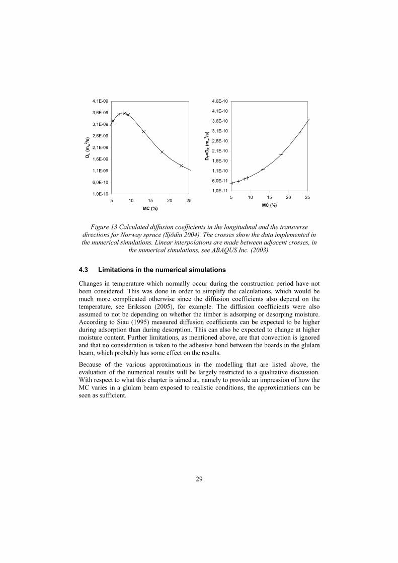
The moisture simulation involved transient moisture flow. The moisture content on the wood surface is assumed to be in equilibrium with the surroundings, so that when the RH is changed the MC on the surface reaches the equilibrium MC immediately. Thus, convection is ignored in the transient moisture flow simulation. The diffusion coefficients used in the simulation were chosen in accordance with Figure 13, which should correspond to Norway spruce stored at 20 ºC. As can be seen in Figure 13, no consideration was taken to the difference between the radial and the tangential directions. Further theoretical considerations regarding the calculations of the diffusion coefficients and the moisture simulations are discussed in Sjödin (2004).
29
1,0E-11
6,0E-11
1,1E-10
1,6E-10
2,1E-10
2,6E-10
3,1E-10
3,6E-10
4,1E-10
4,6E-10
5 10 15 20 25
MC (%)D
T=D
R (m
w2 /s
)
1,0E-10
6,0E-10
1,1E-09
1,6E-09
2,1E-09
2,6E-09
3,1E-09
3,6E-09
4,1E-09
5 10 15 20 25
MC (%)
DL (
mw
2 /s)
Figure 13 Calculated diffusion coefficients in the longitudinal and the transverse directions for Norway spruce (Sjödin 2004). The crosses show the data implemented in the numerical simulations. Linear interpolations are made between adjacent crosses, in
the numerical simulations, see ABAQUS Inc. (2003).
4.3 Limitations in the numerical simulations
Changes in temperature which normally occur during the construction period have not been considered. This was done in order to simplify the calculations, which would be much more complicated otherwise since the diffusion coefficients also depend on the temperature, see Eriksson (2005), for example. The diffusion coefficients were also assumed to not be depending on whether the timber is adsorping or desorping moisture. According to Siau (1995) measured diffusion coefficients can be expected to be higher during adsorption than during desorption. This can also be expected to change at higher moisture content. Further limitations, as mentioned above, are that convection is ignored and that no consideration is taken to the adhesive bond between the boards in the glulam beam, which probably has some effect on the results.
Because of the various approximations in the modelling that are listed above, the evaluation of the numerical results will be largely restricted to a qualitative discussion. With respect to what this chapter is aimed at, namely to provide an impression of how the MC varies in a glulam beam exposed to realistic conditions, the approximations can be seen as sufficient.

30
4.4 Numerical results
Figure 14 Moisture distribution in a glulam beam during a 120 day period (1 day = 24 hours) caused by the changes in humidity shown in the diagram at the bottom.

31
Figures 14 and 15 show the numerical results for the moisture distribution in the glulam beam at different occasions. As can be seen, on day 1, when the humidity had just been changed from 65 % RH to 90 % RH to simulate the wet conditions present during the construction period, the MC at the surfaces of the glulam beam has risen, whereas the inside of the beam is still unaffected. On days 7 and 14, the inside is still largely unaffected, but the depth of penetration of the moisture has increased. It is of interest to note that already on days 7 and 14 the penetration depth from the end grain surface inwards is clearly greater than from the other surfaces. This is to be expected due to the moisture transport mechanism being much stronger parallel to than perpendicular to the grain, as mentioned in chapter 3. This is even more pronounced on day 60, when the moisture has reached the inside of the beam.
On day 60 the humidity is changed from 90 % RH to 30 % RH in order to simulate the building having been completed and the heating system having been turned on. On day 61, as shown in figures 14 and 15, one can see the effects of this, i.e the MC of the surfaces of the glulam beam is immediately decreased, whereas the inside is still unaffected. It is of interest to note that on day 67 the MC on the inside of the beam is still increasing whereas the surfaces are drying. On days 90 and 120 the inside of the beam is also affected by the low RH. Nevertheless, there are still a large gap in the MC between the inside of the beam and the surface.
56
78
910
1112
131415161718
1920
0 0,03 0,0656
78
910
1112
131415161718
1920
0 0,03 0,06 0,09T (m)
MC
(%)
61
30
60
0
147
1
120
9074
67
Path T
Symm
etry
56
78
910
1112
131415161718
1920
0 0,1 0,2 0,3L (m)
MC
(%)
61
30
60
0
14
7
1 120
90
6774
56
78
910
1112
131415161718
1920
0 0,1 0,2 0,3L (m)
MC
(%)
61
30
60
0
14
7
1 120
90
6774
Path L
Symm
etry
Figure 15 Moisture distribution along two different paths over a 120 day period reflecting changes in humidity (T=across the grain in the middle of the beam and
L=along the grain from the end-grain surface). Results from calculations.

32
4.5 Discussion
It should be borne in mind that a change in MC in timber induces shrinkage and swelling deformations. As the results indicated moisture gradients, see Figures 14 and 15, uneven shrinkage and swelling deformations will occur in the cross-section of the glulam beam. As mentioned in chapter 3, this results in moisture-induced stresses, which can affect both the load-bearing capacity of the glulam beam and induce cracks.
As mentioned above, the numerical results show that the moisture transport mechanism is stronger parallel to the grain then perpendicular to it. This is of special interest in the thesis with respect to the joints being located close to the end grain.
33
5 Effects of restrained shrinkage deformations in the joint area of dowel-type joints
5.1 Introduction
I joints, it is often difficult to avoid shrinkage and swelling deformations being restrained by the fasteners in the joint and at the same time maintain the capacity of the joint. The presence of steel parts in timber joints, which are often needed in order to transmit high loads and to obtain a certain stiffness and capacity of the joint, constitutes a risk owing to the fact that steel does not behave as timber when it is exposed to moisture changes. For a steel-to-timber dowel joint where the steel dowels are fitted both to the timber members and to a steel plate, the dowels will be fixed in position and restrain moisture induced deformations (see Figure 4). How this influences the load-bearing capacity of dowel-type joints loaded parallel to the grain has been the main aim of the work performed in the thesis, which are discussed and summarized in this chapter.
This chapter also contains numerical calculations in order to investigate and compare the stress distribution in the joint induced on one hand only by an external load and on the other hand only by restrained shrinkage deformations by the dowels. The joints studied were the same ones as tested experimentally in papers A and B, see Figure 16. Jorissen (1998) has described the influence that tensile stresses perpendicular to the grain and shear stresses have on such joints. In the present chapter the hypothesis, based on these findings, was that stresses induced, particularly perpendicular to the grain by restrained shrinkage deformations, can interact with the stresses generated in the joints when loaded them to failure. Due to this hypothesis, only stresses perpendicular to the grain are presented and discussed below from the numerical simulations.
Little attentions seem to be paid on the influence of restrained moisture induced deformations for dowel-type joints in the literature. This involves especially dowel-type joints loaded parallel to the grain which is the main aim in this thesis. For small scale dowel-type joints loaded perpendicular to the grain, however, the effect of restrained moisture induced deformations have been studied experimentally, see Gustafsson and Larsen (2001) and Larsen and Gustafsson (2001). The results obtained did not reveal any major influence of restrained moisture induced deformations for the joints tested.

34
Figure 16 Types of joints studied in the experimental part of the thesis (see papers A and B).
5.2 Experimental set-up
The types of joints that were studied are shown in Figure 16. In order to study the effects of restrained moisture-induced deformations, the joints of each type were divided into different categories. The categories differed with respect to the climatic conditions to which the joints were subjected to and when the steel plate and the dowels were fitted into the joints before the joints were loaded to failure. The characteristics of two important categories that will be further discussed here are as follows:
For category 1, the reference category (termed case B in paper A and category B in paper B), the joints were first stored under a climatic condition corresponding to 23ºC and 90% RH for type 1A, and 20ºC and 65% RH for types 1B and 2B. After the equilibrium moisture content had been reached, the climate was changed to a drier one corresponding to 23ºC and 30% RH for type 1A, and 20ºC and 30% RH respectively, for types 1B and 2B. Several days afterward, in that new climate, the steel plate and the steel dowels were fitted to the joints. Directly afterwards, the joints were loaded to failure.
For category 2 (termed case A in paper A and category C in paper B) the joints were exposed to the same climatic conditions as the joints in category 1, but with the major difference that the steel plate and the steel dowels were fitted to the joints before the initial climate was changed to a drier one. Because of this procedure the steel dowels were believed to restrain the moisture-induced deformations and due to that inducing internal stresses. The joints were then loaded to failure.
(mm)

35
In Figure 17 the test conditions discussed above are summarized.
Stage1Manufacturing
Time
Stage2Construction period
Stage2Building in service
RH (%)
65
90
30Day 0
Day 60Day 120
TimeDAY 0
Storage in climate chambers for all joints in order to
achieve initially equilibrium moisture content
TYPE 1A
TYPE 1B and 2B
The steel plate and the steel dowels are fitted to the joints belonging to category 2. The
relative humidity is then changed
DAY 41 DAY 110
Storage in climate chambers for all joints in order to
produce shrinkage deformations
The steel plate and the dowels are fitted to the joints
belonging to category 1, TYPE 1A. All joints in TYPE 1A are then loaded to failure
The steel plate and the dowels are fitted to the joints belonging to
category 1, TYPE 1B and 2B. All joints in TYPE 1B and 2B are then
loaded to failure
Figure 17 Test conditions.
During the loading procedure, the joints were subjected to a displacement-control rate of 0.5 mm/min for type 1A (small scale joints) and 0.9 mm/min for types 1B and 2B (full scale joints). The loading procedure for the large-scale joints belonging to types 1B and 2B in Figure 16 are shown in Figure 18. During the tests for all joints, the load was recorded and the relative displacement between the plate and the timber was measured by two inductive gauges attached on opposite narrow sides of the joints.
Figure 18 Test-arrangement for the type 1B and 2B joints (Note that in the upper picture the gauges are not fitted to the joint).

36
5.3 Experimental results
The results obtained and the visual observations made during storage in the climate chambers for joints belonging to categories 2 are presented first. The results of the load-bearing tests are then presented and discussed. The test conditions and experimental results, which are discussed below, are summarized in Table 1.
Table 1 Test conditions and experimental results.
20°C, 65%RH
20°C, 30%RH
20°C, 65%RH
20°C, 30%RH
5.3.1 Effects during storage in the climate chambers on the category 2 joints
The visible observations made during storage in climate chambers for the small-scale joints (type 1A in Figure 16) were different as compared to the large scale-joints (type 1B and 2B in Figure 16). For the type 1A joints the restrained shrinkage deformations only resulted in a deformed area close to the dowels as shown in Figure 19. For the large-scale joints, moisture induced cracks were also observed in the joint area as shown in Figure 20. These cracks were most significant for the joints with a large distance between the dowel rows, i.e the type 2B joints.

37
Figure 19 Deformed area close to one of the dowels of a type 1A joint belonging to category 2.
Crack
Figure 20 A type 2B joint belonging to category 2, as observed at two occasions: prior to climate change at the left and just before the specimen was loaded to failure at the right.

38
5.3.2 Load-displacement characteristics and general observations
0
5
10
15
20
25
30
35
40
0 1 2 3 4 5
Displacement (mm)
Load
(kN
)
0
5
10
15
20
25
30
35
40
0 1 2 3 4 5
Displacement (mm)
Load
(kN
)
0
50
100
150
200
250
300
350
400
0 1 2 3 4 5
Displacement (mm)
Load
(kN
)
0
50
100
150
200
250
300
350
400
0 1 2 3 4 5
Displacement (mm)
Load
(kN
)
0
50
100
150
200
250
300
350
400
0 1 2 3 4 5
Displacement (mm)
Load
(kN
)
0
50
100
150
200
250
300
350
400
0 1 2 3 4 5
Displacement (mm)
Load
(kN
)
Type 1A
Cat
egor
y 1
Cat
egor
y 2
Type 1B Type 2B
Figure 21 Load-displacement curves for the specimens that were tested.
The load-displacement curves in Figure 21 show that for nearly all of the joints belonging to types 1B and 2B, there is no major ductile behavior. Instead, failure occurred suddenly at the ultimate load, the specimens then no longer being able to carry the load. The results for type 1A joints, however, indicate more ductile behavior. This was, however, not caused by plastic hinges developing in the dowels, but by the embedment failure of the wood which led to marked local deformation.
5.3.3 Comparison of categories and types in terms of load-bearing capacity
Results for the load-bearing capacity of the different types and categories of joints discussed above are shown in Figure 22, see also Table 1. For the small-scale joints (Type 1A) no major influence on the load-bearing capacity can be detected for the joints belonging to category 2 as compared with the reference joints belonging to category 1. As discussed above, same tendencies have been seen for small scale joints loaded perpendicular to the grain as presented in Gustafsson and Larsen (2001) and in Larsen and Gustafsson (2001).

39
In contrast to the small scale joins (Type 1A), a distinct decrease in load-bearing capacity was noted for the large-scale joints (Type 1B and 2B) belonging to category 2 as compared with the reference joints. On the basis of these results, it could be concluded that the steel-to-timber dowel joints can be negatively affected by restrained shrinkage deformations by the dowels, a conclusion that appears not to have been reported in the literature previously. On the basis of the results obtained for the joints of type 1A, it can also be concluded that this behavior depends upon the size of the joints.
Figure 22 Load-bearing capacities for different joint types and categories.
5.4 Numerical simulations of the stress distribution in the joint area
The stresses in the joint area for the three different joint types shown in Figure 16 were simulated for an external load case as well as a moisture case. The FE-software ABAQUS (ABAQUS Inc., 2003) was used for the 2D numerical analyses. The element subdivision in the joint area for each of the joints is shown in Figure 23 (Note that symmetry conditions are employed.). In each of the three joint types, 6-node second-order triangular elements were used. Linear elastic-behavior was assumed for the wood, which is certainly an approximation for the area close to the dowels, where both plastic and viscoelastic deformations occur. The moduli of elasticity and the shear moduli for defining the orthotropic wood material were set to El=15160, Et=505 Er=505, Glr=950, Glt=950 and Grt=95 MPa, being estimated on the basis of the European EN 338 standard. The indices l, r and t denote the longitudinal, radial and tangential directions of the timber, respectively. The Poisson’s ratios used were set to vlr = 0.50, vlt = 0.50 and vrt = 0.70. As can be seen, no consideration was taken of the difference between the radial and the tangential directions. The rough simplification was also made of assuming the elastic properties listed above to not be dependent on the moisture content of the wood.

40
Figure 23 Element subdivisions for the three types of joint studied. The configuration setups are taken from papers B and C, respectively.
For both the external load case and the moisture case, the plate was considered as being infinitely stiff. This is a simplification made due to the stiffness of the steel plate affecting the load distribution over the dowels, as discussed in chapter 2. Since this is believed to have only a slight effect on the stress distribution in the joint area, it is ignored. Assuming the steel plate to be infinitely stiff allows the load in the external load case to be applied simply as a uniform deformation of the dowels in the longitudinal direction. For the moisture case, the dowel translation was locked in all directions. The dowels were also assumed to act as rigid bodies. The interaction between the dowels and the wood material was simulated by contact elements involving friction in the tangential direction of the dowels. This coefficient was set to 0.4 (Dias and Kuilen 2004).
In order to simulate the effects of the shrinkage deformations, so-called initial strains were employed (Ottosen and Petersson 1992). They were calculated by use of the expression = · MC, where is the shrinkage coefficient in the different directions and
MC is the difference in MC expressed as a percentage. The shrinkage coefficients used were those typical of Norway spruce as given in timber handbooks (Carling, 2001 for example). The values chosen were l= 0.0001 in the longitudinal direction and t = 0.002 in the cross-grain direction. No account was taken of the influence of transient moisture flow. A decrease in MC from 12 % to 8 % ( MC = 4 percentage units) was assumed and was simulated for each of the three joint types presented in Figure 16 and 23.

41
5.5 Results of numerical simulations
5.5.1 External load case
The characteristic load-bearing capacity according to Eurocode 5 (2004) for the joints studied in the external load case was estimated to FEC5=30 kN for the type 1A joint and to FEC5=205 kN for the type 1B and 2B joints. Figure 24 (see also Figure 25) shows the stress results corresponding to a tension load parallel to the grain of F = FEC5 for each of the joints.
The result for the type 1A joint show that tensile stresses perpendicular to the grain develop (red areas) in the area between the dowels and the end-grain surface at the free end. Similar tendencies are seen for the types 1B and 2B joints. Note, however, that for the type 1B joint the stresses interact with each other to a larger extent than in the type 2B joint for which the distance between rows is greater. Thus, it seems to be that the rows are working more independently for the type 2B joint as compared to the type 1B joint. This could be an explanation why the load-bearing capacity is greater in each of the categories for the type 2B joints compared to the type 1B joints, as shown in Figure 22 and Table 1.
Figure 24 Stress results perpendicular to the grain on the joint area in the external load case. The deformations are scaled up 10 times.

42
Figure 25 Experimental and some numerical results of the strain distribution in the joint area presented in Paper D. The joint configuration corresponds to the type 1A joint
discuss in this chapter. The experimental results were measured with use of a contact-free measurement system (ARAMISTM).
5.5.2 Moisture case
Figure 26 presents the results of the stresses perpendicular to the grain induced in the moisture case. Because of the various approximations made in the modelling, as discussed above, the stresses obtained are likely to be too high. Nevertheless, the results are informative, which is the major aim here. Note, for example, that there are large tensile stresses close to the dowels for each of the different types of joints. An observation of interest is that the results obtained for the joints of types 1B and 2B indicate that there are large tensile stresses between the dowel rows and in the area close to the end grain surface. Examining the results for type 1A in Figure 26, one can instead note that the moisture-induced stresses to a large extent are simply found locally, around the dowels.

43
Figure 26 Stress distribution perpendicular to the grain caused by moisture induced deformations being restrained during drying from 12 % to 8 % MC. The deformations
are scaled up 10 times.
In comparing types 1B and 2B in Figure 26, one can note that the stresses are slightly greater for type 2B, in which the spacing between the dowel rows is larger. This is a possible explanation to moisture-induced cracks being more common in the type 2B than in the type 1B joints as mentioned earlier. According to the results presented in Figure 22, this does not appear to be a factor that affects the load-bearing capacity of the joints. However, according to the results obtained in paper B for a group of joints that was loaded to failure in a standard climate (12% MC) without any exposure to changes in moisture, the effect of increasing the row-spacing should not be ignored. For the joints of type 2B the mean load-bearing capacity decreased by almost 25 % as compared with this group of joints. For the type 1B joints the decrease was 20 %. For a detailed explanation and discussion of this, the reader is referred to paper B.
5.5.3 Comparing the external load case with the moisture case
If comparing Figure 24 with Figure 26 the results clearly indicate that the stresses perpendicular to the grain in some areas interact with each other. Thus in real situation where the two cases are combined, the moisture-induced stresses will increase the total magnitude of stresses in some areas. This can, for example, be seen in front of the dowels in the load-direction where the external load case as well as the moisture case indicates high tension stresses perpendicular to the grain.

44
An interesting observation of the results obtained for the joints of types 1B and 2B is, as mentioned above, that the results from both cases indicate large tensile stresses between the dowel rows and in the area close to the end grain surface. Same prominent tendencies are not seen in the type 1A joint for the moisture case. This could be the explanation for the finding reported in the experimental work on small-scale joints not being affected by moisture-induced stresses.

45
6 CONCLUDING REMARKS
6.1 Thesis summary and conclusions
A review of the literature on dowel-type joints loaded in tension parallel to the grain and on the relationship between the timber characteristics and the moisture level is presented at the beginning of the thesis. Then results of numerical simulations of the moisture distribution in a glulam beam exposed to realistic conditions was presented. This was followed by a discussion of the effect of restrained shrinkage deformations by the dowels, a discussion based both on the experimental results obtained in the papers that are appended and on a number of supplementary numerical simulations.
Papers A and B present experimental results concerning the influence of initial moisture-induced stresses in the joint area in dowel-type joints loaded in tension parallel to the grain. The moisture induced stresses were, in first hand seen as being induced by shrinkage deformations being restrained perpendicular to the grain by the fasteners in the joints. In paper A, in which small-scale joints were studied, no major influence on the load-bearing capacity could be detected for the joints being initially exposed to this condition. Contact-free measurements and supplementary numerical results in chapter 5 provided an explanation to this by showing the moisture-induced stresses to be very local around the dowels.
In contrast to paper A, a significant decrease in load-bearing capacity, under similar conditions, was detected for the large-scale joints reported in paper B. It was also observed in paper B that the configuration of the joints affected the moisture influence. An increase in spacing between the dowel rows perpendicular to the grain led to the load-bearing capacity being more strongly affected by the moisture change and to an increase in the occurrence of moisture-induced cracks.
An additional observation of interest in paper B was that the load-bearing capacity decreased for a group of joints that were initially exposed to drying without the steel plate and dowels fitted to the joints. Internal stresses caused by moisture gradients were considered to provide possible explanation of this behavior.
The effect of moisture gradients on dowel-type joints was numerically analyzed in paper C. On the basis of the numerical results obtained, it appears reasonable to assume that moisture changes in the joint area can affect the load-bearing capacity of the joints in either a positive way (in case of moistening) or a negative way (in case of drying). It appears that this can be explained by the moisture-induced stresses either interacting with or counteracting the stresses generated by the mechanical load.

46
Paper D presents an experimental method, based on contact-free measurements, for analyzing strains and deformations in the joint area in dowel-type joints. It also presents results of traditional measurement methods and numerical results in order to evaluate the contact-free measurement system involved from a general point of view and also to illustrate the advantages of such a measurement system and the possibilities it provides. The measurement system was found to be a valuable complement to traditional measurement techniques and also to numerical analyses performed in parametric studies. Several observations of considerable interest were made on the basis of the numerical results in combination with the results from the contact-free measurement system. A non-uniform strain distribution in the joint area could be noted. Shear strains and tensile strains, both parallel and perpendicular to the grain were found to be concentrated in the areas most likely to influence the failure mode of the joint.
6.2 Further work
Further experimental and numerical investigations are needed to verify the results obtained, especially those reported in paper B. This concerns in particularly the effects of internal stresses induced by shrinkage deformations being restrained in the joint area by the steel plate and the dowels. If the same results are obtained in a new study, recommendations and restrictions should possibly be placed to design codes to compensate for the influence of moisture changes on dowel-type joints. It is possible that moisture-induced stresses should be considered as a load in design codes.
The numerical results obtained in paper C suggest it to be of interest to study, by means of experimental methods, the effects of moisture gradients on dowel-type joints, both during drying and during moistening. Use of contact-free measurement methods can be a valuable tool here for investigating the extent to which tensile strains tend to be induced in the joint area by moisture gradients.
An experimental study of the effects of different configuration setups in the joint area would be of interest. In the thesis, attention was mainly directed at the spacing between the dowel rows perpendicular to the grain. The effects of changes in other parameters as well as of adding eccentricity to the joint have scarcely been dealt with in the literature. Contact-free measurement methods together with numerical analysis could definitely be an alternative way to increase the knowledge of such joint behaviors.

47
7 REFERENCES
ABAQUS Inc. (2003). ABAQUS/Standard and ABAQUS/CAE Version 6.4, User Manuals.
Aicher, R. R., Dill-Langer, G. and Ranta-Maunus, A. (1998) Duration of load effect in tension perpendicular to the grain of glulam in different climates. Holz als Roh- und Werkstoff, Vol. 56, pp. 295-305.
Blass, H. J. (2003) Joints with dowel-type fasteners. Timber Engineering. Thelandersson and Larsen, H.J., Eds, Wiley & Sons, ISBN 0-470-84469-8.
Carling, O. (2001) The glulam handbook (in Swedish), Svenskt Limträ AB, Stockholm
Cramer, C. O. (1968) Load distribution in multiple-bolt tension joints. Jour. of the Structural Div, ASCE, 94, pp. 1101-1117.
Dias, A. and Kuilen, J.W.G. (2004) Non-linear FEM models for timber-concrete joints made with dowel type fasteners. Proceedings of the 8th World Conference on Timber Engineering, Vol. 1, Lahti, Finland
Dinwoodie, J.M. (2000) Timber: Its nature and behavior. Second edition, E. & F. N. Spoon, London,
Eriksson, J. (2005). Moisture transport and moisture induced distortions in timber – an experimental and numerical study. Ph.D. thesis, Chalmers University of Technology, Göteborg, Sweden.
Eurocode 5. (2004) Eurocode 5 - Design of timber structures. EN 1995-1-1:2004(E).
Gustafsson, P. J., Hoffmeyer, P. and Valentin, G. (1998) DOL behavior of end-notched beams. Holz als Roh- und Werkstoff, Vol. 56, pp. 307-317.
Gustafsson, P. J. and Larsen, H. J. (2001) Dowel joints loaded perpendicular to grain. Proceedings of the International RILEM Symposium, Stuttgart, Germany.
Hoffmeyer, P. (1995) Wood as a building material. Timber Engineering STEP 1. Steck, G., Eds, Centrum Hout, ISBN 90-5645-001-8.
Isyumov, N., (1969) Load distribution in multiple shear-plate joints in timber. Pub. Non. 1203, Canada Department of Forestry.
Johansen, K.W. (1949) Theory of timber connections. International Association of Bridge and Strucural Engineering 9:, 249-262
Jorissen, A. (1998) Double shear timber connections with dowel type fasteners. Ph.D. thesis, Delft University, Delft, The Netherlands.

48
Jönsson, J. and Thelandersson, S. (2003) The effect of moisture gradients on tensile strength perpendicular to grain in glulam. Holz als Roh- und Werkstoff, Vol. 61, pp. 342-348.
Lantos, G. (1967) Load distribution in a row of fasteners subjected to lateral load. Wood Science 1 (3), 129-136
Larsen, H. J. and Gustafsson, P. J. (2001) Dowel joints loaded perpendicular to grain. Proceedings of the CIB W18 Meeting, paper CIB-W18/34-7-4.
Nevander, L. E. and Elmarsson, B. (2001) Handbook of moisture (in Swedish) Svensk Byggtjänst, Stockholm
Ottosen, N. and Petersson. P. (1992) Introduction to the finite element method. Prentice Hall London.
Pedersen, M. U., Clorius, O., Damkilde, L., Hoffmeyer, P., and Eskildsen, L. (1999) Dowel type connections with slotted-in steel plates. Proceedings of the CIB W18 Meeting, paper CIB-W18/32-7-8.
Persson, K. (1997) Modelling of wood properties by a micromechanical approach. Licentiate thesis, Report TVSM-3020, Lund Institute of Technology, Divition of Structural Mechanics, Lund, Sweden.
Quenneville, J. H. P. (1997) Group effects in bolted timber connections. Proceedings of the Canadian Society for Civil Engineering, Vol. 7, Sherbrooke, Québec, Canada
Quenneville, J. H. P., and Mohammad, M. (2000) On the failure modes and strength of steel-to-timber bolted connections loaded parallel-to-grain. Can. J. Eng., 27, 761-773.
Rammer, D. R. and Winistorfer, S. G. (2001) Effect of moisture content on dowel-bearing strength. Wood and Fiber Science., 33(1), pp. 136-139.
Rammer, D. R. (2001) Effect of moisture content on nail bearing strength. Res. Pap. FPL-RP-591. Madison, WI: U.S. Department of Agriculture, Forest Service, Forest Products Laboratory. 22p.
Ranta-Maunus, A. (2003) Effects of climate and climate variations on strength. Timber Engineering. Larsen, H.J., Eds, Wiley & Sons, ISBN 0-470-84469-8.
Racher, P. (1995) Mechanical timber joints - General. Timber Engineering STEP 1. Steck, G., Eds, Centrum Hout, ISBN 90-5645-001-8.
Siau, J.F. (1995) WOOD: Influence of moisture on physical properties. Department of wood science and forest products, Virgina Polytechnic and State University
Sjödin, J. (2004) Moisture transport in glulam during the construction phase (in Swedish), KTH, TRITA-BYMA 2004:3, ISSN 0349-5752
Skaar, C. (1988) Wood-water relations. Springer-Verlag, Berlin Heildelberg,
Wilkinson, T. L. (1986) Load distribution among bolt parallel to load. Jour. of Structural Engineering, ASCE, 112(No. 4), 835-852.